EP4410239A1 - Intraocular lens insertion tool - Google Patents
Intraocular lens insertion tool Download PDFInfo
- Publication number
- EP4410239A1 EP4410239A1 EP22875836.3A EP22875836A EP4410239A1 EP 4410239 A1 EP4410239 A1 EP 4410239A1 EP 22875836 A EP22875836 A EP 22875836A EP 4410239 A1 EP4410239 A1 EP 4410239A1
- Authority
- EP
- European Patent Office
- Prior art keywords
- intraocular lens
- slider
- rod
- motion
- injector
- Prior art date
- Legal status (The legal status is an assumption and is not a legal conclusion. Google has not performed a legal analysis and makes no representation as to the accuracy of the status listed.)
- Pending
Links
Images



Classifications
-
- A—HUMAN NECESSITIES
- A61—MEDICAL OR VETERINARY SCIENCE; HYGIENE
- A61F—FILTERS IMPLANTABLE INTO BLOOD VESSELS; PROSTHESES; DEVICES PROVIDING PATENCY TO, OR PREVENTING COLLAPSING OF, TUBULAR STRUCTURES OF THE BODY, e.g. STENTS; ORTHOPAEDIC, NURSING OR CONTRACEPTIVE DEVICES; FOMENTATION; TREATMENT OR PROTECTION OF EYES OR EARS; BANDAGES, DRESSINGS OR ABSORBENT PADS; FIRST-AID KITS
- A61F2/00—Filters implantable into blood vessels; Prostheses, i.e. artificial substitutes or replacements for parts of the body; Appliances for connecting them with the body; Devices providing patency to, or preventing collapsing of, tubular structures of the body, e.g. stents
- A61F2/02—Prostheses implantable into the body
- A61F2/14—Eye parts, e.g. lenses or corneal implants; Artificial eyes
- A61F2/16—Intraocular lenses
- A61F2/1662—Instruments for inserting intraocular lenses into the eye
- A61F2/1678—Instruments for inserting intraocular lenses into the eye with a separate cartridge or other lens setting part for storage of a lens, e.g. preloadable for shipping
-
- A—HUMAN NECESSITIES
- A61—MEDICAL OR VETERINARY SCIENCE; HYGIENE
- A61F—FILTERS IMPLANTABLE INTO BLOOD VESSELS; PROSTHESES; DEVICES PROVIDING PATENCY TO, OR PREVENTING COLLAPSING OF, TUBULAR STRUCTURES OF THE BODY, e.g. STENTS; ORTHOPAEDIC, NURSING OR CONTRACEPTIVE DEVICES; FOMENTATION; TREATMENT OR PROTECTION OF EYES OR EARS; BANDAGES, DRESSINGS OR ABSORBENT PADS; FIRST-AID KITS
- A61F2/00—Filters implantable into blood vessels; Prostheses, i.e. artificial substitutes or replacements for parts of the body; Appliances for connecting them with the body; Devices providing patency to, or preventing collapsing of, tubular structures of the body, e.g. stents
- A61F2/02—Prostheses implantable into the body
- A61F2/14—Eye parts, e.g. lenses or corneal implants; Artificial eyes
- A61F2/16—Intraocular lenses
- A61F2/1662—Instruments for inserting intraocular lenses into the eye
- A61F2/1672—Instruments for inserting intraocular lenses into the eye with a two-stage plunger, e.g. rotatable and pushable or rotatable at different speeds
-
- A—HUMAN NECESSITIES
- A61—MEDICAL OR VETERINARY SCIENCE; HYGIENE
- A61F—FILTERS IMPLANTABLE INTO BLOOD VESSELS; PROSTHESES; DEVICES PROVIDING PATENCY TO, OR PREVENTING COLLAPSING OF, TUBULAR STRUCTURES OF THE BODY, e.g. STENTS; ORTHOPAEDIC, NURSING OR CONTRACEPTIVE DEVICES; FOMENTATION; TREATMENT OR PROTECTION OF EYES OR EARS; BANDAGES, DRESSINGS OR ABSORBENT PADS; FIRST-AID KITS
- A61F2/00—Filters implantable into blood vessels; Prostheses, i.e. artificial substitutes or replacements for parts of the body; Appliances for connecting them with the body; Devices providing patency to, or preventing collapsing of, tubular structures of the body, e.g. stents
- A61F2/02—Prostheses implantable into the body
- A61F2/14—Eye parts, e.g. lenses or corneal implants; Artificial eyes
- A61F2/16—Intraocular lenses
- A61F2002/1681—Intraocular lenses having supporting structure for lens, e.g. haptics
-
- A—HUMAN NECESSITIES
- A61—MEDICAL OR VETERINARY SCIENCE; HYGIENE
- A61F—FILTERS IMPLANTABLE INTO BLOOD VESSELS; PROSTHESES; DEVICES PROVIDING PATENCY TO, OR PREVENTING COLLAPSING OF, TUBULAR STRUCTURES OF THE BODY, e.g. STENTS; ORTHOPAEDIC, NURSING OR CONTRACEPTIVE DEVICES; FOMENTATION; TREATMENT OR PROTECTION OF EYES OR EARS; BANDAGES, DRESSINGS OR ABSORBENT PADS; FIRST-AID KITS
- A61F2250/00—Special features of prostheses classified in groups A61F2/00 - A61F2/26 or A61F2/82 or A61F9/00 or A61F11/00 or subgroups thereof
- A61F2250/0058—Additional features; Implant or prostheses properties not otherwise provided for
- A61F2250/0065—Additional features; Implant or prostheses properties not otherwise provided for telescopic
Definitions
- the present invention relates to an intraocular lens injector.
- an intraocular lens is injected into a lens capsule to replace the crystalline lens, and an intraocular lens injector is used to inject the intraocular lens.
- an intraocular lens injector equipped with a slider mechanism configured such that an intraocular lens that has been placed in the injector in advance is moved by a slider, folded into a small size, and then folded into a smaller size by a rod before being ejected from the injector, is known (for example, see Patent document 1).
- Patent Document 1 Patent Publication No. 5413918
- Folding the intraocular lens with the intraocular lens injector includes tucking a rear support portion of the intraocular lens.
- the slider simultaneously performs tucking of the rear support portion and folding of the intraocular lens. Therefore, it was necessary to temporarily suppress the folding of the intraocular lens using a folding control unit formed at a tip of the slider, to prevent interference between the tacked rear support portion and the folded intraocular lens.
- the rod pushes the intraocular lens that is restrained and not properly folded, there is a risk of abrupt or uncontrolled ejection of the intraocular lens.
- the present invention provides a technique for a smooth and controllable ejection of an intraocular lens from an intraocular lens injector equipped with a slider mechanism.
- First aspect of the present invention provides an intraocular lens injector for injecting into an eye an intraocular lens having an optical portion and a pair of support portions extending from the optical portion, comprising:
- a second aspect of the present invention provides the intraocular lens injector according to the first aspect, wherein the intraocular lens injector has, as a range of motion of the slider and the rod, a third range of motion where the intraocular lens at the predetermined position is pushed out of the injector main body by moving the rod which is out of connection with the slider.
- a third aspect of the present invention provides the intraocular lens injector according to the first or second aspect, wherein the slider is configured to make contact with the intraocular lens at a plurality of points.
- a fourth aspect of the present invention provides the intraocular lens injector according to any one of the first to third aspects, wherein the slider and the rod are configured so that the movement of the rod is guided by the sliders that sandwich the rod.
- a fifth aspect of the present invention provides the intraocular lens injector according to any one of the first to fourth aspects,
- the intraocular lens in an intraocular lens injector equipped with a slider mechanism, the intraocular lens can be stably ejected.
- FIG. 1 is a perspective view illustrating an example of a configuration of the intraocular lens injector.
- the intraocular lens injector 1 is used when injecting an intraocular lens 4 (not illustrated in FIG. 1 ) into an eye.
- the intraocular lens 4 comprises a soft material such as silicone elastomer or soft acrylic, and has a circular optical portion 4a that performs an optical function, and a pair of support portions 4b extending from an outer periphery of the optical portion 4a (for example, see FIG. 3 below). Since the intraocular lens 4 is well known, detailed explanation thereof will be omitted here.
- the intraocular lens injector 1 is roughly divided into an injector main body 5, a slider 6, a nozzle portion 7, a plunger 9, and a rod 10 connected to the plunger 9 (not illustrated in FIG. 1 ).
- Each of these components is preferably formed of a resin molded product.
- the injector main body 5 is formed into a hollow tubular shape, and a nozzle portion 7 is connected to one end of the tube.
- the other end of the tube is provided with a flange 14 and an opening through which the plunger 9 and rod 10 can be inserted into the tube.
- a lens housing portion 11 (not illustrated in FIG. 1 ) that houses the intraocular lens 4 to be injected is provided within the tube of the injector main body 5.
- the slider 6 is attached to the injector main body 5 and is arranged to be movable along an axial direction of the injector main body 5 (X-axis direction in FIG. 1 ).
- the axial direction of the injector main body 5 matches an injection direction when injecting the intraocular lens 4 housed in the injector main body 5 into an eye.
- one of the X-axis directions is defined as X1 direction, and the other is defined as X2 direction, with the X1 direction being a front side (tip side) in the injection direction, with the X2 direction being a rear side (rear end side) in the injection direction. That is, the slider 6 is arranged movably along the injection direction (X-axis direction) of the intraocular lens 4.
- the intraocular lens 4 housed in the lens housing portion 11 is pushed forward in the injection direction (X1 direction).
- the nozzle portion 7 is for folding the intraocular lens 4 housed in the injector main body 5 into a small size and guiding it into an eye when the intraocular lens 4 is injected into the eye.
- the nozzle portion 7 has a lens outlet on a tip side, and a cross-sectional area of an internal space is configured to gradually become narrower from the side of the injector main body 5 toward the lens outlet.
- the plunger 9 is arranged coaxially with the injector main body 5 and is arranged movably along the injection direction of the intraocular lens 4 (X-axis direction in FIG. 1 ).
- a stick-like rod 10 extending along the axial direction within the tube of the injection main body 5 is connected to the plunger 9. Accordingly, when the plunger 9 moves, the rod 10 arranged within the tube of the injector main body 5 also moves along the injection direction of the intraocular lens 4. That is, the rod 10 connected to the plunger 9 is also arranged movably along the injection direction of the intraocular lens 4.
- the plunger 9 and rod 10 move along the injection direction of the intraocular lens 4 in the same way as the slider 6, but the movement is performed separately from the slider 6 or in connection with the slider 6.
- the intraocular lens injector 1 configured as described above, when a user of the intraocular lens injector 1 (for example, a doctor performing cataract surgery) moves the slider 6, the intraocular lens 4 housed in the lens housing portion 11 within the injector main body 5 moves to a predetermined position on a front side in the injection direction. Thereby, the intraocular lens 4 is folded into a small size. Then, when the user moves the plunger 9, the rod 10 connected to the plunger 9 folds the intraocular lens 4 at a predetermined position into a further smaller size and pushes it outward. Thereby, the intraocular lens 4 is ejected from the lens outlet of the nozzle portion 7.
- the intraocular lens injector 1 is equipped with a slider mechanism of folding the intraocular lens 4 using the slider 6.
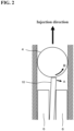
- FIG. 2 is an explanatory view illustrating a specific example of the risk that may occur in the intraocular lens injector equipped with a slider mechanism.
- the rod 10 pushes out the intraocular lens 4, thereby ejecting the intraocular lens 4 from the injector.
- the rod 10 deviates from its normal path and contacts the lens at an angle due to inclination or bending of the rod 10 (see arrow A in the figure), this can create a force that rotates the lens, caused by the pushing of the rod 10 (see arrow B in the figure). That is, regarding the intraocular lens 4 ejected by the rod 10, there is a risk that a rotational force will be applied (hereinafter simply referred to as a "rotation risk").
- Such a rotation risk leads to an unstable ejection of the intraocular lens 4.
- the position of the support portions 4a and 4b of the intraocular lens 4 that is about to be ejected may be misaligned, and the user of the intraocular lens injector may not be able to perform the ejecting operation as expected, and may experience poor operability.
- the rotation risk should be eliminated before it occurs.
- the folding includes tacking of the support portion 4b on the rear side in the injection direction (hereinafter, simply referred to as a "rear support portion.") out of the pair of support portions 4b of the intraocular lens 4.
- the slider 6 is used to tuck the rear support portion 4b. That is, the slider 6 not only has a function of moving the intraocular lens 4 within the injector, but also has a function of tacking the rear support portion 4b. For this reason, in the intraocular lens injector with a conventional configuration, an end shape of the slider 6 needs to be more complex and larger in order to perform multiple functions, which results in limiting a limiting amount of movement (stroke) toward the tip end of the nozzle portion 7 whose cross-sectional area gradually becomes narrower.
- stroke of the slider 6 When the stroke of the slider 6 is limited, the slider 6 cannot advance forward in the injection direction from there, and therefore the slider 6 cannot guide the rod 10 forward from there. Accordingly, this is not necessarily sufficient in terms of eliminating the rotation risk.
- the conventional intraocular lens injector involves the following problem: since the slider 6 has the function of tacking the rear support portion 4b, it is not necessarily possible to eliminate the rotation risk, and users of the intraocular lens injector experience poor operability.
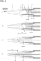
- FIG. 3 is an explanatory view (part 1) illustrating an example of the configuration of the main part of the intraocular lens injector 1 according to an embodiment of the present invention.
- the intraocular lens injector 1 houses the intraocular lens 4 in the lens housing portion 11 in the injector main body 5 so that the intraocular lens 4 can be ejected from the lens outlet of the nozzle portion 7.
- the intraocular lens 4 is ejected by moving the slider 6 and the rod 10 forward in the injection direction.
- the slider 6 and the rod 10 may be moved separately or may be moved in connection each other.
- the slider 6 and the rod 10 are each configured such that the movement of the rod 10 is guided by the sliders 6 that sandwich the rod 10.
- the slider 6 and the rod 10 are in connection each other using engaging portions 12a and 12b (see FIGS. 3(a) to 3(d) ) provided therein respectively, and each connection can be canceled using elastic deformation of at least one of the slider 6 or the rod 10.
- connection state between the slider 6 and the rod 10 can be adjusted as desired (relative positions of the parts of the slider 6 and the rod 10 that touch the intraocular lens 4 in the advancing direction can be adjusted arbitrarily.), and by adjusting the connection state between the slider 6 and the rod 10, the degree of folding the tip of the rear support portion 4b in the advancing direction can be adjusted.
- a range of motion of the slider 6 and rod 10 is configured as illustrated in FIGS. 3(a) to 3(d) . More specifically, the slider 6 and the rod 10 have a first range of motion S1, a second range of motion S2, and a third range of motion S3.
- the first range of motion S1 is a range of motion in which the rod 10 mainly moves, and by this movement, this is a range of motion for tacking the rear support portion 4b of the pair of support portions 4b of the intraocular lens 4 in the lens housing portion 11.
- "Tacking" here refers to folding the rear support portion 4b toward a front side in the injection direction, and it does not matter whether or not the tip of the rear support portion 4b after folding is pushed between the folded optical portions 4a.
- the rod 10 has a function of tacking the rear support portion 4b. Therefore, the slider 6 does not need to have a tacking function, and the end face shape can be prevented from becoming more complex and larger than in the case of the conventional configuration described above.
- the rod 10 In the first range of motion S1, it is sufficient that the rod 10 is movable, and there is no need to move the slider 6. However, the slider 6 may be allowed to move as long as the rear support portion 4b can be tacked by the rod 10.
- the second range of motion S2 is a range of motion in which the slider 6 and the rod 10 move together in connection each other, and this is a range of motion for moving the intraocular lens 4 with the rear support portion 4b tacked, from the lens housing portion 11 to a predetermined position on the front side in the injection direction.
- the optical portion 4a of the intraocular lens 4 is folded into a small size while the rear support portion 4b remains in a tacked state.
- the slider 6 and the rod 10 are in connection each other to move the intraocular lens 4, and since the sliders 6 are configured to sandwich the rod 10, the slider 6 comes into contact with the intraocular lens 4 at a plurality of points (specifically, two points on both sides of the rod 10).
- the rotation risk of the intraocular lens 4 can be suppressed to a lower level compared to the case where the intraocular lens 4 is pushed out using only the rod 10.
- a protrusion 7a for temporarily stopping the optical portion 4a of the intraocular lens 4 is provided on a side wall that guides the movement of the intraocular lens 4, it becomes possible to adjust the position of the intraocular lens 4 at this point, which is required in order to reduce the rotation risk of the intraocular lens 4.
- the intraocular lens 4 is moved to a predetermined position on the front side in the injection direction, and since the end face shape can be prevented from becoming more complex and larger, it is possible to bring the predetermined position closer to the lens outlet of the nozzle portion 7, that is, to ensure a sufficient stroke of the slider 6 to the tip side of the nozzle portion 7, compared to the conventional configuration described above.
- the stroke of the slider 6 that is sufficiently ensured to the tip side allows the folding of the intraocular lens 4 to be promoted more than before, that is, a more stable state of the intraocular lens 4 can be obtained by bringing the intraocular lens 4 into closer contact with an inner surface of the nozzle portion 7 than before.
- the third range of motion S3 is a range of motion for moving the rod 10 that is not connected with the slider 6, and this is a range of motion for pushing out the intraocular lens 4 at a predetermined position from the lens outlet of the nozzle portion 7 (that is, outside the injector main body 5).
- the intraocular lens 4 is pushed out by the rod 10, and in this case, by bringing a predetermined position, which is a position before being pushed out, closer to the lens outlet of the nozzle portion 7, a sufficient range for guiding the rod 10 by the slider 6 can be ensured. Accordingly, it is possible to effectively prevent the rod 10 from deviating from its normal path and suppress the rotation risk of the intraocular lens 4, compared to the case of the conventional configuration described above.
- the slider 6 and the rod 10 each operate in connection each other or separately.
- the mechanism for this purpose is not particularly limited, and may be any mechanism that is appropriately configured (designed) depending on the purpose. Specific operating modes of the slider 6 and the rod 10 will be described in detail later.
- the intraocular lens injector 1 has the following configuration.
- FIG. 4 is an explanatory view (part 2) illustrating an example of the configuration of a main part of the intraocular lens injector 1 according to this embodiment.
- a lower surface of the rear support portion 4b needs to be located at least higher than an upper end of an outer periphery of the optical portion 4a of the intraocular lens 4 (see dashed arrow in the figure).
- the slider 6 is formed with a slope portion 6a for guiding the rear support portion 4b to the upper side of the optical portion 4a, and an end surface 10a of the rod 10 is formed in a shape capable of pressing the rear support portion 4b.
- the first range of motion S1 when the rod 10 moves forward in the direction of injection (inj ection direction) (see arrow C in the figure), the end surface 10a of the rod 10 presses against the rear support portion 4b of the intraocular lens 4.
- the rear support portion 4b is guided by the slope portion 6a and moves toward the upper side of the optical portion 4a (see arrow D in the figure). Then, when the rear support portion 4b reaches the upper side of the optical portion 4a, the rear support portion 4b is tucked. After tucking the rear support portion 4b, in the second range of motion S2, the optical portion 4a and the rear support portion 4b are pressed by the end surface 10a of the rod 10, and the optical portion 4a is also pressed by the slider 6.
- the slider 6 is formed with the slope portion 6a is exemplified here, the present invention is not limited thereto, and the slope portion 6a may be formed in the lens housing portion 11.
- a slope portion 11a for guiding movement of the rod 10 may be formed in the lens housing portion 11.
- a pressing surface 10b for pressing the rear support portion 4b of the intraocular lens 4 and a pressing surface 10c for pressing the optical portion 4a of the intraocular lens 4 are formed on the end edge of the rod 10.
- the pressing surface 10b of the rod 10 presses the rear support portion 4b, and moves the rear support portion 4b toward the upper side of the optical portion 4a while being guided by the slope portion 11a (see arrow F in the figure), so that the rear support portion 4b is tucked.
- the optical portion 4a is pressed by the pressing surface 10c of the rod 10 (see arrow G in the figure) while the rear support portion 4b is pressed by the pressing surface 10b of the rod 10 (see arrow F in the figure), and further the optical portion 4a is also pressed by the slider 6. This causes the intraocular lens 4 to move forward in the injection direction.
- FIGS. 5 and 6 are explanatory views illustrating examples of the operation of the intraocular lens injector 1 according to this embodiment.
- the intraocular lens injector 1 when using the intraocular lens injector 1, it is assumed that the intraocular lens injector 1 is attached to a case 3, with the intraocular lens 4 preset in the lens housing portion 11. That is, after being shipped from a manufacturing factory, the intraocular lens injector 1 is attached to a special case 3 during transportation, preparation for surgery, etc. This prevents the preset intraocular lens 4 from being unnecessarily ejected or damaged.
- a user of the intraocular lens injector 1 first operates a slider tab 6c of the intraocular lens injector 1 manually moving the slider tab 6c forward in the injection direction of the intraocular lens 4 (see arrow in the figure).
- the slider tab 6c operated by the user constitutes a part of the slider 6, and is arranged to be movable along the injection direction of the intraocular lens 4 like the slider 6 and rod 10, and performs the operation in connection with the slider 6 and rod 10.
- the slider tab 6c and the rod 10 are formed to engage with each other (see section H in the enlarged view). With this configuration, as the slider tab 6c moves, the rod 10 also moves forward in the injection direction.
- a specific manner of engagement between the slider tab 6c and the rod 10 is not limited, for example, as shown in section H in the figure, it is minimally necessary for them to engage with each other by providing a through hole in the center of the slider tab 6c in the Y direction, passing the rod 10 through this through hole, and making the X1 direction side of the rod 10 wider than the through hole.
- the slider tab 6c engages not only with the rod 10 but also with the slider 6 (see part I in the figure).
- this engagement mode is not limited, for example, as illustrated in part I in the figure, the shape of the slider tab 6c on the X1 direction side and the shape of the slider 6 on the X2 direction side may be shaped to fit into each other.
- both the slider 6 and the rod 10 move forward in the injection direction together with the movement of the slider tab 6c, because the slider tab 6c is engaged not only with the rod 10 but also with the slider 6.
- the movement of the slider 6 and the rod 10 at this time corresponds to the movement in the second range of motion S2. That is, the slider tab 6c causes the slider 6 and the rod 10 to move in the second range of motion S2, in connection with the slider 6 and the rod 10.
- the intraocular lens 4 with the rear support portion 4b tacked is pushed forward in the injection direction by both the slider 6 and the rod 10.
- the slider 6 contacts the intraocular lens 4 at a plurality of points (specifically, two points on both sides of the rod 10). Therefore, the risk of intraocular lens 4 rotation is lowered compared to a case where the intraocular lens 4 is pushed out using only the rod 10.
- the slider 6 and the rod 10 are moved until the intraocular lens 4 reaches a predetermined position on the front side in the injection direction.
- the end face shape of the slider 6 can be prevented from becoming more complex and larger, it is possible to bring the predetermined position closer to the lens outlet of the nozzle portion 7, that is, to ensure a sufficient stroke of the slider 6 to the tip side of the nozzle portion 7, compared to the conventional configuration described above.
- the intraocular lens injector 1 is disengaged from the case 3 and can be removed from the case 3, as illustrated in FIG. 6(b) .
- the user of the intraocular lens injector 1 injects the intraocular lens 4 housed in the intraocular lens injector 1 into the eye of a subject (patient).
- the user of the intraocular lens injector 1 manually operates the plunger 9 of the intraocular lens injector 1, as illustrated in FIG. 6(c) , and causes the rod 10 connected to the plunger 9 to move forward in the injection direction of the intraocular lens 4 (see the arrow in the figure).
- the movement of the rod 10 at this time corresponds to the movement in the third range of motion S3. That is, the plunger 9 causes the connected rod 10 to move in the third range of motion S3.
- the rod 10 having been out of connection with the slider tab 6c can move only the rod 10 forward in the injection direction (X1 direction).
- the intraocular lens 4 at a predetermined position is pushed forward in the injection direction by the rod 10, and is ejected to the outside from the lens outlet of the nozzle portion 7 when passing through the nozzle portion 7, while being folded into a small size.
- the rod 10 that pushes out the intraocular lens 4 has been out of connection with the slider 6, and is guided forward in the injection direction by the slider 6. Therefore, by bringing the predetermined position, which is the position before being pushed out, closer to the lens outlet of the nozzle part 7, a sufficient guide range by the slider 6 can be ensured, and it is possible to effectively prevent the rod 10 from deviating from its normal path thereby lowering the risk of intraocular lens 4 rotation, compared to the case of the conventional configuration described above.
- the intraocular lens 4, which is ejected from the lens outlet of the nozzle portion 7, is injected into the eye of the subject. That is, by injecting the tip of the nozzle portion 7 of the intraocular lens injector 1 into the eye and ejecting the intraocular lens 4 from the lens outlet of the nozzle portion 7 in this state, the user of the intraocular lens injector 1 achieves the injection of the intraocular lens 4 into the eye.
- the slider 6 since the rod 10 has a function of tacking the rear support portion 4b, the slider 6 does not have to have the tacking function, and compared to the conventional configuration described above, the end face shape can be prevented from becoming more complex and larger. Further, since the slider 6 and the rod 10 are in connection each other to move the intraocular lens 4 in the second range of motion S2, the risk of intraocular lens 4 rotation is lowered, compared to the case where the intraocular lens 4 is pushed out using only the rod 10. In addition, although the intraocular lens 4 is moved to a predetermined position on the front side in the injection direction in the second range of motion S2, the end face shape of the slider 6 can be prevented from becoming more complex and larger. Therefore, it is possible to bring the predetermined position closer to the lens outlet of the nozzle portion 7, that is, to ensure a sufficient stroke of the slider 6 to the tip side of the nozzle portion 7, compared to the conventional configuration described above.
- the intraocular lens injector 1 equipped with a slider mechanism, the intraocular lens 4 can be stably ejected.
- the slider 6 and the rod 10 have the third range of motion S3 in addition to the first range of motion S1 and the second range of motion S2. Then, by moving the rod 10 having been out of connection with the slider 6 in the third range of motion S3, the intraocular lens 4 at a predetermined position is pushed out of the injector main body from the lens outlet of the nozzle portion 7.
- the slider 6 is configured to come into contact with the intraocular lens 4 at a plurality of points. Accordingly, this is very effective in lowering the risk of intraocular lens 4 rotation when the slider 6 moves the intraocular lens 4.
- the slider 6 and the rod 10 are configured to guide the movement of the rod 10 by the sliders 6 that sandwiches the rod 10. Accordingly, this is very effective in effectively preventing the rod 10 from deviating from its normal path and reducing the rotation risk of the intraocular lens 4.
- the intraocular lens 4 includes a slider tab 6c that is movably arranged along the injection direction of the intraocular lens 4, and the slider tab 6c is configured to operate in connection with the slider 6 and the rod 10. That is, the slider tab 6c causes the rod 10 to move in the first range of motion S1 in connection with the rod 10, and causes the slider 6 and the rod 10 to move in the second range of motion S2 in connection with the slider 6 and the rod 10.
- this embodiment enables the following situation: the user of the intraocular lens injector 1 causes the rod 10 to move in the first range of motion S1, and causes the slider 6 and rod 10 to move in the second range of motion S2, by operating (moving) the slider tab 6c. That is, for the user of the intraocular lens injector 1, this provides excellent operability, which is preferable for stably performing the operation of ejecting the intraocular lens 4.
- each component of the intraocular lens injector 1 is formed of a resin molded product.
- the present invention is not limited thereto, and each component of the intraocular lens injector 1 may be formed of a metal member such as stainless steel or titanium.
- Intraocular lens injector 4... Intraocular lens, 4a... Optical portion, 4b... Support portion (rear support portion), 5... Injector main body, 6... Slider, 7... Nozzle portion, 9... Plunger, 10... Rod, 11... Lens housing portion, S1... First range of motion, S2... Second range of motion, S3... Third range of motion
Landscapes
- Health & Medical Sciences (AREA)
- Ophthalmology & Optometry (AREA)
- Cardiology (AREA)
- Oral & Maxillofacial Surgery (AREA)
- Transplantation (AREA)
- Engineering & Computer Science (AREA)
- Biomedical Technology (AREA)
- Heart & Thoracic Surgery (AREA)
- Vascular Medicine (AREA)
- Life Sciences & Earth Sciences (AREA)
- Animal Behavior & Ethology (AREA)
- General Health & Medical Sciences (AREA)
- Public Health (AREA)
- Veterinary Medicine (AREA)
- Prostheses (AREA)
Abstract
Description
- The present invention relates to an intraocular lens injector.
- In cataract surgery, after removing a cloudy crystalline lens, an intraocular lens is injected into a lens capsule to replace the crystalline lens, and an intraocular lens injector is used to inject the intraocular lens. The concept of an intraocular lens injector equipped with a slider mechanism configured such that an intraocular lens that has been placed in the injector in advance is moved by a slider, folded into a small size, and then folded into a smaller size by a rod before being ejected from the injector, is known (for example, see Patent document 1).
- [Patent Document 1] Patent Publication No.
5413918 - Folding the intraocular lens with the intraocular lens injector includes tucking a rear support portion of the intraocular lens. In the intraocular lens injector equipped with a slider mechanism described above, the slider simultaneously performs tucking of the rear support portion and folding of the intraocular lens. Therefore, it was necessary to temporarily suppress the folding of the intraocular lens using a folding control unit formed at a tip of the slider, to prevent interference between the tacked rear support portion and the folded intraocular lens. When the rod pushes the intraocular lens that is restrained and not properly folded, there is a risk of abrupt or uncontrolled ejection of the intraocular lens.
- The present invention provides a technique for a smooth and controllable ejection of an intraocular lens from an intraocular lens injector equipped with a slider mechanism.
- First aspect of the present invention provides an intraocular lens injector for injecting into an eye an intraocular lens having an optical portion and a pair of support portions extending from the optical portion, comprising:
- an injector main body having a lens housing portion for housing the intraocular lens to be injected,
- a slider movably arranged along an injection direction of the intraocular lens which pushes out the intraocular lens housed in the lens housing portion, and
- a stick-like rod movably arranged along the injection direction, separate from the slider or in connection with the slider;
- the intraocular lens injector having, as a range of motion of the slider and the rod:
- a first range of motion where a rear support portion of the pair of support portions in the intraocular lens in the lens housing portion is tucked by a movement of the rod, and
- a second range of motion where the intraocular lens is moved from the lens housing portion to a predetermined position on the forward side of the injection direction by interlocking the slider and the rod while the rear support portion of the lens is being tacked.
- A second aspect of the present invention provides the intraocular lens injector according to the first aspect,
wherein the intraocular lens injector has, as a range of motion of the slider and the rod, a third range of motion where the intraocular lens at the predetermined position is pushed out of the injector main body by moving the rod which is out of connection with the slider. - A third aspect of the present invention provides the intraocular lens injector according to the first or second aspect,
wherein the slider is configured to make contact with the intraocular lens at a plurality of points. - A fourth aspect of the present invention provides the intraocular lens injector according to any one of the first to third aspects,
wherein the slider and the rod are configured so that the movement of the rod is guided by the sliders that sandwich the rod. - A fifth aspect of the present invention provides the intraocular lens injector according to any one of the first to fourth aspects,
- further comprising a slider tab movably arranged along the injection direction,
- wherein the slider tab is configured to be in connection with the rod to cause the rod to move in the first range of motion, and to be in connection with the slider and the rod to cause the slider and the rod to move in the second range of motion. Advantage of the Invention
- According to the present invention, in an intraocular lens injector equipped with a slider mechanism, the intraocular lens can be stably ejected.
-
-
FIG. 1 is a perspective view illustrating an example of a configuration of an intraocular lens injector according to an embodiment of the present invention. -
FIG. 2 is an explanatory view illustrating a specific example of a risk that may occur in an intraocular lens injector equipped with a slider mechanism. -
FIG. 3 is an explanatory view (part 1) illustrating an example of the configuration of a main part of an intraocular lens injector according to an embodiment of the present invention. -
FIG. 4 is an explanatory view (part 2) illustrating an example of the configuration of a main part of the intraocular lens injector according to an embodiment of the present invention. -
FIG. 5 is an explanatory view (Part 1) illustrating an example of a processing operation in the intraocular lens injector according to an embodiment of the present invention. -
FIG. 6 is an explanatory view (part 2) illustrating an example of a processing operation in the intraocular lens injector according to an embodiment of the present invention. - Embodiments of the present invention will be described below based on the drawings.
- First, a basic configuration of an intraocular lens injector will be explained.
-
FIG. 1 is a perspective view illustrating an example of a configuration of the intraocular lens injector. - The
intraocular lens injector 1 is used when injecting an intraocular lens 4 (not illustrated inFIG. 1 ) into an eye. Theintraocular lens 4 comprises a soft material such as silicone elastomer or soft acrylic, and has a circularoptical portion 4a that performs an optical function, and a pair ofsupport portions 4b extending from an outer periphery of theoptical portion 4a (for example, seeFIG. 3 below). Since theintraocular lens 4 is well known, detailed explanation thereof will be omitted here. - In order to inject the
intraocular lens 4 into an eye, as illustrated inFIG. 1 , theintraocular lens injector 1 is roughly divided into an injector main body 5, aslider 6, anozzle portion 7, aplunger 9, and arod 10 connected to the plunger 9 (not illustrated inFIG. 1 ). Each of these components is preferably formed of a resin molded product. - The injector main body 5 is formed into a hollow tubular shape, and a
nozzle portion 7 is connected to one end of the tube. The other end of the tube is provided with aflange 14 and an opening through which theplunger 9 androd 10 can be inserted into the tube. A lens housing portion 11 (not illustrated inFIG. 1 ) that houses theintraocular lens 4 to be injected is provided within the tube of the injector main body 5. - The
slider 6 is attached to the injector main body 5 and is arranged to be movable along an axial direction of the injector main body 5 (X-axis direction inFIG. 1 ). The axial direction of the injector main body 5 matches an injection direction when injecting theintraocular lens 4 housed in the injector main body 5 into an eye. Below, for explaining the injection direction of theintraocular lens 4, one of the X-axis directions is defined as X1 direction, and the other is defined as X2 direction, with the X1 direction being a front side (tip side) in the injection direction, with the X2 direction being a rear side (rear end side) in the injection direction. That is, theslider 6 is arranged movably along the injection direction (X-axis direction) of theintraocular lens 4. Thereby, theintraocular lens 4 housed in thelens housing portion 11 is pushed forward in the injection direction (X1 direction). - The
nozzle portion 7 is for folding theintraocular lens 4 housed in the injector main body 5 into a small size and guiding it into an eye when theintraocular lens 4 is injected into the eye. For this purpose, thenozzle portion 7 has a lens outlet on a tip side, and a cross-sectional area of an internal space is configured to gradually become narrower from the side of the injector main body 5 toward the lens outlet. - The
plunger 9 is arranged coaxially with the injector main body 5 and is arranged movably along the injection direction of the intraocular lens 4 (X-axis direction inFIG. 1 ). A stick-like rod 10 extending along the axial direction within the tube of the injection main body 5 is connected to theplunger 9. Accordingly, when theplunger 9 moves, therod 10 arranged within the tube of the injector main body 5 also moves along the injection direction of theintraocular lens 4. That is, therod 10 connected to theplunger 9 is also arranged movably along the injection direction of theintraocular lens 4. Theplunger 9 androd 10 move along the injection direction of theintraocular lens 4 in the same way as theslider 6, but the movement is performed separately from theslider 6 or in connection with theslider 6. - In the
intraocular lens injector 1 configured as described above, when a user of the intraocular lens injector 1 (for example, a doctor performing cataract surgery) moves theslider 6, theintraocular lens 4 housed in thelens housing portion 11 within the injector main body 5 moves to a predetermined position on a front side in the injection direction. Thereby, theintraocular lens 4 is folded into a small size. Then, when the user moves theplunger 9, therod 10 connected to theplunger 9 folds theintraocular lens 4 at a predetermined position into a further smaller size and pushes it outward. Thereby, theintraocular lens 4 is ejected from the lens outlet of thenozzle portion 7. - That is, the
intraocular lens injector 1 is equipped with a slider mechanism of folding theintraocular lens 4 using theslider 6. - Here, the risk that may occur in an intraocular lens injector equipped with a slider mechanism will be briefly explained.
-
FIG. 2 is an explanatory view illustrating a specific example of the risk that may occur in the intraocular lens injector equipped with a slider mechanism. - In the intraocular lens injector equipped with a slider mechanism, the
rod 10 pushes out theintraocular lens 4, thereby ejecting theintraocular lens 4 from the injector. In some cases, as illustrated inFIG. 2 , if therod 10 deviates from its normal path and contacts the lens at an angle due to inclination or bending of the rod 10 (see arrow A in the figure), this can create a force that rotates the lens, caused by the pushing of the rod 10 (see arrow B in the figure). That is, regarding theintraocular lens 4 ejected by therod 10, there is a risk that a rotational force will be applied (hereinafter simply referred to as a "rotation risk"). - Such a rotation risk leads to an unstable ejection of the
intraocular lens 4. Specifically, when the rotational force is applied to theintraocular lens 4, the position of thesupport portions intraocular lens 4 that is about to be ejected may be misaligned, and the user of the intraocular lens injector may not be able to perform the ejecting operation as expected, and may experience poor operability. - Accordingly, the rotation risk should be eliminated before it occurs. In order to eliminate the rotation risk, it is necessary to prevent the
rod 10 from deviating from its normal path. Specifically, in order to prevent therod 10 from deviating from its normal path, it is necessary to guide the forward movement of therod 10 by theslider 6 while limiting the size of the gap between theslider 6 and therod 10. - However, in the conventional intraocular lens injector disclosed in
Patent document 1, the rotation risk cannot always be eliminated for the reasons described below. - In the intraocular lens injector equipped with a slider mechanism of folding the
intraocular lens 4 into a small size and then ejecting it, the folding includes tacking of thesupport portion 4b on the rear side in the injection direction (hereinafter, simply referred to as a "rear support portion.") out of the pair ofsupport portions 4b of theintraocular lens 4. - In the conventional intraocular lens injector, the
slider 6 is used to tuck therear support portion 4b. That is, theslider 6 not only has a function of moving theintraocular lens 4 within the injector, but also has a function of tacking therear support portion 4b. For this reason, in the intraocular lens injector with a conventional configuration, an end shape of theslider 6 needs to be more complex and larger in order to perform multiple functions, which results in limiting a limiting amount of movement (stroke) toward the tip end of thenozzle portion 7 whose cross-sectional area gradually becomes narrower. When the stroke of theslider 6 is limited, theslider 6 cannot advance forward in the injection direction from there, and therefore theslider 6 cannot guide therod 10 forward from there. Accordingly, this is not necessarily sufficient in terms of eliminating the rotation risk. - That is, the conventional intraocular lens injector involves the following problem: since the
slider 6 has the function of tacking therear support portion 4b, it is not necessarily possible to eliminate the rotation risk, and users of the intraocular lens injector experience poor operability. - This is a new finding obtained by the inventor of the present application. Based on this new finding, the inventor of the present application devised an
intraocular lens injector 1 described in this embodiment in order to eliminate the above-described risk and to stably perform the ejection operation of theintraocular lens 4. - Next, a characteristic configuration of a main part of the
intraocular lens injector 1 according to this embodiment will be explained. -
FIG. 3 is an explanatory view (part 1) illustrating an example of the configuration of the main part of theintraocular lens injector 1 according to an embodiment of the present invention. - As illustrated in
FIG. 3(a) , theintraocular lens injector 1 houses theintraocular lens 4 in thelens housing portion 11 in the injector main body 5 so that theintraocular lens 4 can be ejected from the lens outlet of thenozzle portion 7. Theintraocular lens 4 is ejected by moving theslider 6 and therod 10 forward in the injection direction. - The
slider 6 and therod 10 may be moved separately or may be moved in connection each other. For this kind of behavior, theslider 6 and therod 10 are each configured such that the movement of therod 10 is guided by thesliders 6 that sandwich therod 10. Theslider 6 and therod 10 are in connection each other usingengaging portions FIGS. 3(a) to 3(d) ) provided therein respectively, and each connection can be canceled using elastic deformation of at least one of theslider 6 or therod 10. Further, the connection state between theslider 6 and therod 10 can be adjusted as desired (relative positions of the parts of theslider 6 and therod 10 that touch theintraocular lens 4 in the advancing direction can be adjusted arbitrarily.), and by adjusting the connection state between theslider 6 and therod 10, the degree of folding the tip of therear support portion 4b in the advancing direction can be adjusted. - Then, in this embodiment, when moving the
slider 6 androd 10, a range of motion of theslider 6 androd 10 is configured as illustrated inFIGS. 3(a) to 3(d) . More specifically, theslider 6 and therod 10 have a first range of motion S1, a second range of motion S2, and a third range of motion S3. - As illustrated in
FIGS. 3(a) and 3(b) , the first range of motion S1 is a range of motion in which therod 10 mainly moves, and by this movement, this is a range of motion for tacking therear support portion 4b of the pair ofsupport portions 4b of theintraocular lens 4 in thelens housing portion 11. "Tacking" here refers to folding therear support portion 4b toward a front side in the injection direction, and it does not matter whether or not the tip of therear support portion 4b after folding is pushed between the foldedoptical portions 4a. - That is, in this embodiment, the
rod 10 has a function of tacking therear support portion 4b. Therefore, theslider 6 does not need to have a tacking function, and the end face shape can be prevented from becoming more complex and larger than in the case of the conventional configuration described above. - In the first range of motion S1, it is sufficient that the
rod 10 is movable, and there is no need to move theslider 6. However, theslider 6 may be allowed to move as long as therear support portion 4b can be tacked by therod 10. - As illustrated in
FIGS. 3(b) and 3(c) , the second range of motion S2 is a range of motion in which theslider 6 and therod 10 move together in connection each other, and this is a range of motion for moving theintraocular lens 4 with therear support portion 4b tacked, from thelens housing portion 11 to a predetermined position on the front side in the injection direction. When theintraocular lens 4 is moved to a predetermined position, theoptical portion 4a of theintraocular lens 4 is folded into a small size while therear support portion 4b remains in a tacked state. - In the second range of motion S2, the
slider 6 and therod 10 are in connection each other to move theintraocular lens 4, and since thesliders 6 are configured to sandwich therod 10, theslider 6 comes into contact with theintraocular lens 4 at a plurality of points (specifically, two points on both sides of the rod 10). - Accordingly, the rotation risk of the
intraocular lens 4 can be suppressed to a lower level compared to the case where theintraocular lens 4 is pushed out using only therod 10. At this time, when aprotrusion 7a for temporarily stopping theoptical portion 4a of theintraocular lens 4 is provided on a side wall that guides the movement of theintraocular lens 4, it becomes possible to adjust the position of theintraocular lens 4 at this point, which is required in order to reduce the rotation risk of theintraocular lens 4. - Further, in the second range of motion S2, the
intraocular lens 4 is moved to a predetermined position on the front side in the injection direction, and since the end face shape can be prevented from becoming more complex and larger, it is possible to bring the predetermined position closer to the lens outlet of thenozzle portion 7, that is, to ensure a sufficient stroke of theslider 6 to the tip side of thenozzle portion 7, compared to the conventional configuration described above. The stroke of theslider 6 that is sufficiently ensured to the tip side allows the folding of theintraocular lens 4 to be promoted more than before, that is, a more stable state of theintraocular lens 4 can be obtained by bringing theintraocular lens 4 into closer contact with an inner surface of thenozzle portion 7 than before. - As illustrated in
FIG. 3(d) , the third range of motion S3 is a range of motion for moving therod 10 that is not connected with theslider 6, and this is a range of motion for pushing out theintraocular lens 4 at a predetermined position from the lens outlet of the nozzle portion 7 (that is, outside the injector main body 5). - In the third range of motion S3, the
intraocular lens 4 is pushed out by therod 10, and in this case, by bringing a predetermined position, which is a position before being pushed out, closer to the lens outlet of thenozzle portion 7, a sufficient range for guiding therod 10 by theslider 6 can be ensured. Accordingly, it is possible to effectively prevent therod 10 from deviating from its normal path and suppress the rotation risk of theintraocular lens 4, compared to the case of the conventional configuration described above. - In the first range of motion S1, second range of motion S2, and third range of motion S3 as described above, the
slider 6 and therod 10 each operate in connection each other or separately. However, the mechanism for this purpose is not particularly limited, and may be any mechanism that is appropriately configured (designed) depending on the purpose. Specific operating modes of theslider 6 and therod 10 will be described in detail later. - As described above, in the first range of motion S1, the movement of the
rod 10 is used to tack therear support portion 4b. For this purpose, theintraocular lens injector 1 has the following configuration. -
FIG. 4 is an explanatory view (part 2) illustrating an example of the configuration of a main part of theintraocular lens injector 1 according to this embodiment. - As illustrated in
FIG. 4(a) , when tacking therear support portion 4b of theintraocular lens 4, a lower surface of therear support portion 4b needs to be located at least higher than an upper end of an outer periphery of theoptical portion 4a of the intraocular lens 4 (see dashed arrow in the figure). - For this purpose, for example, when the
intraocular lens 4 is installed horizontally in the lens housing portion 11 (in other words, when the pair ofsupport portions 4b are installed so as to be located at the same height) as illustrated inFIG. 4(b) , theslider 6 is formed with a slope portion 6a for guiding therear support portion 4b to the upper side of theoptical portion 4a, and anend surface 10a of therod 10 is formed in a shape capable of pressing therear support portion 4b. Then, in the first range of motion S1, when therod 10 moves forward in the direction of injection (inj ection direction) (see arrow C in the figure), theend surface 10a of therod 10 presses against therear support portion 4b of theintraocular lens 4. At this time, therear support portion 4b is guided by the slope portion 6a and moves toward the upper side of theoptical portion 4a (see arrow D in the figure). Then, when therear support portion 4b reaches the upper side of theoptical portion 4a, therear support portion 4b is tucked. After tucking therear support portion 4b, in the second range of motion S2, theoptical portion 4a and therear support portion 4b are pressed by theend surface 10a of therod 10, and theoptical portion 4a is also pressed by theslider 6. Although the case in which theslider 6 is formed with the slope portion 6a is exemplified here, the present invention is not limited thereto, and the slope portion 6a may be formed in thelens housing portion 11. - Further, for example, as illustrated in
FIG. 4(c) , when theintraocular lens 4 is installed obliquely at an angle so that a front side in the injection direction is lower in thelens housing portion 11, the slope portion 6a described above is not required, and aflat guide surface 6b may be formed on theslider 6. For such a configuration, in the first range of motion S1, when therod 10 moves forward in the injection direction (see arrow C in the figure), theend surface 10a of therod 10 presses against therear support portion 4b of theintraocular lens 4. At this time, since theintraocular lens 4 is inclined, therear support portion 4b is guided by theguide surface 6b and moves upward of theoptical portion 4a (see arrow D in the figure). Then, when therear support portion 4b reaches the upper side of theoptical portion 4a, therear support portion 4b is tucked. After therear support portion 4b is tucked, the process is the same as that described above. - Further, for example, as illustrated in
FIG. 4(d) , when theintraocular lens 4 is installed obliquely in thelens housing portion 11, aslope portion 11a for guiding movement of therod 10 may be formed in thelens housing portion 11. For such a configuration, apressing surface 10b for pressing therear support portion 4b of theintraocular lens 4 and apressing surface 10c for pressing theoptical portion 4a of theintraocular lens 4 are formed on the end edge of therod 10. Then, in the first range of motion S1, when therod 10 moves forward in the injection direction (see arrow E in the figure), thepressing surface 10b of therod 10 presses therear support portion 4b, and moves therear support portion 4b toward the upper side of theoptical portion 4a while being guided by theslope portion 11a (see arrow F in the figure), so that therear support portion 4b is tucked. Thereafter, in the second range of motion S2, theoptical portion 4a is pressed by thepressing surface 10c of the rod 10 (see arrow G in the figure) while therear support portion 4b is pressed by thepressing surface 10b of the rod 10 (see arrow F in the figure), and further theoptical portion 4a is also pressed by theslider 6. This causes theintraocular lens 4 to move forward in the injection direction. - Next, as an example of the operation of the
intraocular lens injector 1 having the above-described configuration, specific operating modes of theslider 6 and therod 10 will be described. -
FIGS. 5 and6 are explanatory views illustrating examples of the operation of theintraocular lens injector 1 according to this embodiment. - As illustrated in
FIG. 5(a) , when using theintraocular lens injector 1, it is assumed that theintraocular lens injector 1 is attached to acase 3, with theintraocular lens 4 preset in thelens housing portion 11. That is, after being shipped from a manufacturing factory, theintraocular lens injector 1 is attached to aspecial case 3 during transportation, preparation for surgery, etc. This prevents the presetintraocular lens 4 from being unnecessarily ejected or damaged. - Then, a user of the
intraocular lens injector 1 first operates aslider tab 6c of theintraocular lens injector 1 manually moving theslider tab 6c forward in the injection direction of the intraocular lens 4 (see arrow in the figure). Theslider tab 6c operated by the user constitutes a part of theslider 6, and is arranged to be movable along the injection direction of theintraocular lens 4 like theslider 6 androd 10, and performs the operation in connection with theslider 6 androd 10. - When the
slider tab 6c moves forward in the injection direction, theslider tab 6c and therod 10 are formed to engage with each other (see section H in the enlarged view). With this configuration, as theslider tab 6c moves, therod 10 also moves forward in the injection direction. Although a specific manner of engagement between theslider tab 6c and therod 10 is not limited, for example, as shown in section H in the figure, it is minimally necessary for them to engage with each other by providing a through hole in the center of theslider tab 6c in the Y direction, passing therod 10 through this through hole, and making the X1 direction side of therod 10 wider than the through hole. In this mode, when theslider tab 6c is moved forward in the X1 direction, therod 10 and theslider tab 6c engage with each other, and theslider tab 6c and therod 10 move forward together. The movement ofrod 10 at this time corresponds to the movement in the first range of motion S1. That is, theslider tab 6c causes therod 10 to move in the first range of motion S1, in connection with therod 10. - Accordingly, in the first range of motion S1, as illustrated in
FIG. 5(b) , when therod 10 moves, the presetrear support portion 4b of theintraocular lens 4 is pushed forward in the injection direction by therod 10. That is, by moving therod 10, therear support portion 4b of theintraocular lens 4 is tucked. - When the movement of the first range of motion S1 is completed and the
rear support portion 4b is in a tacked state, theslider tab 6c engages not only with therod 10 but also with the slider 6 (see part I in the figure). Although this engagement mode is not limited, for example, as illustrated in part I in the figure, the shape of theslider tab 6c on the X1 direction side and the shape of theslider 6 on the X2 direction side may be shaped to fit into each other. - Thereafter, when the user continues to move the
slider tab 6c, as illustrated inFIG. 6(a) , both theslider 6 and therod 10 move forward in the injection direction together with the movement of theslider tab 6c, because theslider tab 6c is engaged not only with therod 10 but also with theslider 6. The movement of theslider 6 and therod 10 at this time corresponds to the movement in the second range of motion S2. That is, theslider tab 6c causes theslider 6 and therod 10 to move in the second range of motion S2, in connection with theslider 6 and therod 10. - Accordingly, when the
slider 6 and therod 10 move in the second range of motion S2, theintraocular lens 4 with therear support portion 4b tacked is pushed forward in the injection direction by both theslider 6 and therod 10. At this time, theslider 6 contacts theintraocular lens 4 at a plurality of points (specifically, two points on both sides of the rod 10). Therefore, the risk ofintraocular lens 4 rotation is lowered compared to a case where theintraocular lens 4 is pushed out using only therod 10. - Then, the
slider 6 and therod 10 are moved until theintraocular lens 4 reaches a predetermined position on the front side in the injection direction. At this time, since the end face shape of theslider 6 can be prevented from becoming more complex and larger, it is possible to bring the predetermined position closer to the lens outlet of thenozzle portion 7, that is, to ensure a sufficient stroke of theslider 6 to the tip side of thenozzle portion 7, compared to the conventional configuration described above. - When the
intraocular lens 4 reaches the predetermined position and completes the movement in the second range of motion S2, at that stage, theintraocular lens injector 1 is disengaged from thecase 3 and can be removed from thecase 3, as illustrated inFIG. 6(b) . - Thereafter, the user of the
intraocular lens injector 1 injects theintraocular lens 4 housed in theintraocular lens injector 1 into the eye of a subject (patient). Specifically, the user of theintraocular lens injector 1 manually operates theplunger 9 of theintraocular lens injector 1, as illustrated inFIG. 6(c) , and causes therod 10 connected to theplunger 9 to move forward in the injection direction of the intraocular lens 4 (see the arrow in the figure). The movement of therod 10 at this time corresponds to the movement in the third range of motion S3. That is, theplunger 9 causes the connectedrod 10 to move in the third range of motion S3. At this time, therod 10 having been out of connection with theslider tab 6c, can move only therod 10 forward in the injection direction (X1 direction). - Accordingly, when the
rod 10 moves in the third range of motion S3, theintraocular lens 4 at a predetermined position is pushed forward in the injection direction by therod 10, and is ejected to the outside from the lens outlet of thenozzle portion 7 when passing through thenozzle portion 7, while being folded into a small size. - At this time, the
rod 10 that pushes out theintraocular lens 4 has been out of connection with theslider 6, and is guided forward in the injection direction by theslider 6. Therefore, by bringing the predetermined position, which is the position before being pushed out, closer to the lens outlet of thenozzle part 7, a sufficient guide range by theslider 6 can be ensured, and it is possible to effectively prevent therod 10 from deviating from its normal path thereby lowering the risk ofintraocular lens 4 rotation, compared to the case of the conventional configuration described above. - Through the processing operations described above, the
intraocular lens 4, which is ejected from the lens outlet of thenozzle portion 7, is injected into the eye of the subject. That is, by injecting the tip of thenozzle portion 7 of theintraocular lens injector 1 into the eye and ejecting theintraocular lens 4 from the lens outlet of thenozzle portion 7 in this state, the user of theintraocular lens injector 1 achieves the injection of theintraocular lens 4 into the eye. - According to this embodiment, one or more of the following effects can be obtained.
-
- (a) In this embodiment, the
slider 6 and therod 10 have at least the first range of motion S1 and the second range of motion S2. Then, in the first range of motion S1, therod 10 moves to tack therear support portion 4b, and in the second range of motion S2, theslider 6 and therod 10 move in connection with therod 10, to move theintraocular lens 4 to a predetermined position. - That is, since the
rod 10 has a function of tacking therear support portion 4b, theslider 6 does not have to have the tacking function, and compared to the conventional configuration described above, the end face shape can be prevented from becoming more complex and larger. Further, since theslider 6 and therod 10 are in connection each other to move theintraocular lens 4 in the second range of motion S2, the risk ofintraocular lens 4 rotation is lowered, compared to the case where theintraocular lens 4 is pushed out using only therod 10. In addition, although theintraocular lens 4 is moved to a predetermined position on the front side in the injection direction in the second range of motion S2, the end face shape of theslider 6 can be prevented from becoming more complex and larger. Therefore, it is possible to bring the predetermined position closer to the lens outlet of thenozzle portion 7, that is, to ensure a sufficient stroke of theslider 6 to the tip side of thenozzle portion 7, compared to the conventional configuration described above. - Accordingly, in this embodiment, it becomes possible to eliminate the risk that the ejection operation of the
intraocular lens 4 becomes unstable, and according to theintraocular lens injector 1 equipped with a slider mechanism, theintraocular lens 4 can be stably ejected. - (b) In this embodiment, the
slider 6 and therod 10 have the third range of motion S3 in addition to the first range of motion S1 and the second range of motion S2. Then, by moving therod 10 having been out of connection with theslider 6 in the third range of motion S3, theintraocular lens 4 at a predetermined position is pushed out of the injector main body from the lens outlet of thenozzle portion 7. - Accordingly, in this embodiment, a sufficient range in which the
rod 10 is guided by theslider 6 can be ensured. Therefore, it is possible to effectively prevent therod 10 from deviating from its normal path and lower the risk ofintraocular lens 4 rotation compared to the case of the conventional configuration described above. - (c) In this embodiment, the
slider 6 is configured to come into contact with theintraocular lens 4 at a plurality of points. Accordingly, this is very effective in lowering the risk ofintraocular lens 4 rotation when theslider 6 moves theintraocular lens 4. - (d) In this embodiment, the
slider 6 and therod 10 are configured to guide the movement of therod 10 by thesliders 6 that sandwiches therod 10. Accordingly, this is very effective in effectively preventing therod 10 from deviating from its normal path and reducing the rotation risk of theintraocular lens 4. - (e) In this embodiment, the
intraocular lens 4 includes aslider tab 6c that is movably arranged along the injection direction of theintraocular lens 4, and theslider tab 6c is configured to operate in connection with theslider 6 and therod 10. That is, theslider tab 6c causes therod 10 to move in the first range of motion S1 in connection with therod 10, and causes theslider 6 and therod 10 to move in the second range of motion S2 in connection with theslider 6 and therod 10. - Accordingly, this embodiment enables the following situation: the user of the
intraocular lens injector 1 causes therod 10 to move in the first range of motion S1, and causes theslider 6 androd 10 to move in the second range of motion S2, by operating (moving) theslider tab 6c. That is, for the user of theintraocular lens injector 1, this provides excellent operability, which is preferable for stably performing the operation of ejecting theintraocular lens 4. - The embodiments of the present invention have been described above, but the disclosures described above indicate exemplary embodiments of the present invention. That is, the technical scope of the present invention is not limited to the above-described exemplary embodiments, and various changes can be made without departing from the claimed subject matter.
- For example, the embodiment described above shows a case in which each component of the
intraocular lens injector 1 is formed of a resin molded product. However, the present invention is not limited thereto, and each component of theintraocular lens injector 1 may be formed of a metal member such as stainless steel or titanium. - 1... Intraocular lens injector, 4... Intraocular lens, 4a... Optical portion, 4b... Support portion (rear support portion), 5... Injector main body, 6... Slider, 7... Nozzle portion, 9... Plunger, 10... Rod, 11... Lens housing portion, S1... First range of motion, S2... Second range of motion, S3... Third range of motion
Claims (5)
- An intraocular lens injector for injecting into an eye an intraocular lens having an optical portion and a pair of support portions extending from the optical portion, comprising:an injector main body having a lens housing portion for housing the intraocular lens to be injected,a slider movably arranged along an injection direction of the intraocular lens which pushes out the intraocular lens housed in the lens housing portion, anda stick-like rod movably arranged along the injection direction, separate from the slider or in connection with the slider;the intraocular lens injector having, as a range of motion of the slider and the rod:a first range of motion where a rear support portion of the pair of support portions in the intraocular lens in the lens housing portion is tucked by a movement of the rod, anda second range of motion where the intraocular lens is moved from the lens housing portion to a predetermined position on the forward side of the injection direction by interlocking the slider and the rod while the rear support portion of the lens is being tacked.
- The intraocular lens injector according to claim 1,
wherein the intraocular lens injector has, as a range of motion of the slider and the rod, a third range of motion where the intraocular lens at the predetermined position is pushed out of the injector main body by moving the rod which is out of connection with the slider. - The intraocular lens injector according to claim 1 or 2,
wherein the slider is configured to make contact with the intraocular lens at a plurality of points. - The intraocular lens injector according to any one of claims 1 to 3,
wherein the slider and the rod are configured so that the movement of the rod is guided by the sliders that sandwich the rod. - The intraocular lens injector according to any one of claims 1 to 4,further comprising a slider tab movably arranged along the injection direction,wherein the slider tab is configured to be in connection with the rod to cause the rod to move in the first range of motion, and to be in connection with the slider and the rod to cause the slider and the rod to move in the second range of motion.
Applications Claiming Priority (2)
| Application Number | Priority Date | Filing Date | Title |
|---|---|---|---|
| JP2021161856A JP7886694B2 (en) | 2021-09-30 | 2021-09-30 | Intraocular lens insertion device |
| PCT/JP2022/034398 WO2023053965A1 (en) | 2021-09-30 | 2022-09-14 | Intraocular lens insertion tool |
Publications (2)
| Publication Number | Publication Date |
|---|---|
| EP4410239A1 true EP4410239A1 (en) | 2024-08-07 |
| EP4410239A4 EP4410239A4 (en) | 2025-09-17 |
Family
ID=85782432
Family Applications (1)
| Application Number | Title | Priority Date | Filing Date |
|---|---|---|---|
| EP22875836.3A Pending EP4410239A4 (en) | 2021-09-30 | 2022-09-14 | TOOL FOR INSERTING AN INTRAOCULAR LENS |
Country Status (5)
| Country | Link |
|---|---|
| US (1) | US20240415634A1 (en) |
| EP (1) | EP4410239A4 (en) |
| JP (1) | JP7886694B2 (en) |
| CN (1) | CN117580546A (en) |
| WO (1) | WO2023053965A1 (en) |
Families Citing this family (1)
| Publication number | Priority date | Publication date | Assignee | Title |
|---|---|---|---|---|
| JP7327956B2 (en) | 2019-03-13 | 2023-08-16 | Hoya株式会社 | Intraocular lens insertion device |
Family Cites Families (11)
| Publication number | Priority date | Publication date | Assignee | Title |
|---|---|---|---|---|
| JPS5713875Y2 (en) | 1977-06-30 | 1982-03-20 | ||
| FR2822055B1 (en) * | 2001-03-16 | 2003-09-12 | Lab Contactologie Appl Lca | INTRAOCULAR LENS INJECTOR |
| US7131976B2 (en) * | 2002-05-08 | 2006-11-07 | Canon-Staar Co. Inc. | Insertion device for intraocular lens |
| US8747465B2 (en) * | 2007-05-30 | 2014-06-10 | Hoya Corporation | Intraocular lens insertion device |
| JP5323420B2 (en) * | 2008-08-21 | 2013-10-23 | Hoya株式会社 | Intraocular lens insertion device |
| JP5416379B2 (en) * | 2008-09-04 | 2014-02-12 | Hoya株式会社 | Intraocular lens insertion device |
| US8740977B2 (en) * | 2008-12-01 | 2014-06-03 | Kowa Company, Ltd. | Intraocular lens insertion tool |
| WO2010079780A1 (en) * | 2009-01-07 | 2010-07-15 | Hoya株式会社 | Intraocular lens insertion device |
| WO2010105678A1 (en) * | 2009-03-18 | 2010-09-23 | Ophthalmo Pharma Ag | Device for holding folding and injecting an intraocular lens |
| JP5511530B2 (en) * | 2010-06-10 | 2014-06-04 | Hoya株式会社 | Intraocular lens insertion device |
| JP6276619B2 (en) * | 2014-03-19 | 2018-02-07 | Hoya株式会社 | Intraocular lens insertion device and intraocular lens insertion device |
-
2021
- 2021-09-30 JP JP2021161856A patent/JP7886694B2/en active Active
-
2022
- 2022-09-14 US US18/694,985 patent/US20240415634A1/en active Pending
- 2022-09-14 WO PCT/JP2022/034398 patent/WO2023053965A1/en not_active Ceased
- 2022-09-14 EP EP22875836.3A patent/EP4410239A4/en active Pending
- 2022-09-14 CN CN202280043898.3A patent/CN117580546A/en active Pending
Also Published As
| Publication number | Publication date |
|---|---|
| JP7886694B2 (en) | 2026-07-08 |
| WO2023053965A1 (en) | 2023-04-06 |
| EP4410239A4 (en) | 2025-09-17 |
| US20240415634A1 (en) | 2024-12-19 |
| CN117580546A (en) | 2024-02-20 |
| JP2023051283A (en) | 2023-04-11 |
Similar Documents
| Publication | Publication Date | Title |
|---|---|---|
| US10799339B2 (en) | Intraocular lens injector | |
| US10849738B2 (en) | Intraocular lens injector | |
| US11938019B2 (en) | Intraocular lens insertion device | |
| EP3938013B1 (en) | Automatic injection system | |
| EP2074961B1 (en) | Intraocular lens injection instrument | |
| KR20190104319A (en) | Intraocular lens injector | |
| US20240415634A1 (en) | Intraocular lens injector | |
| WO2022054619A1 (en) | Intraocular-lens insertion instrument and method of designing same | |
| US12478467B2 (en) | Intraocular lens injector | |
| CN111481321B (en) | Pre-installed intraocular lens implant device | |
| JP6614615B2 (en) | Intraocular lens insertion device | |
| CN210204985U (en) | Pre-assembled intraocular lens implantation device | |
| KR20170137849A (en) | Guide lens insertion mechanism | |
| JP2026078736A (en) | Intraocular lens insertion device | |
| US20210267753A1 (en) | Intraocular lens insertion apparatus | |
| CN209864172U (en) | Injection component of artificial lens implanter and artificial lens implanter | |
| JP2024145347A (en) | Intraocular lens insertion device | |
| US20260021251A1 (en) | Medication injection system | |
| CN118141566A (en) | Intraocular lens injector and method of operating an intraocular lens injector | |
| HK40046126A (en) | Intraocular lens insertion instrument |
Legal Events
| Date | Code | Title | Description |
|---|---|---|---|
| STAA | Information on the status of an ep patent application or granted ep patent |
Free format text: STATUS: THE INTERNATIONAL PUBLICATION HAS BEEN MADE |
|
| PUAI | Public reference made under article 153(3) epc to a published international application that has entered the european phase |
Free format text: ORIGINAL CODE: 0009012 |
|
| STAA | Information on the status of an ep patent application or granted ep patent |
Free format text: STATUS: REQUEST FOR EXAMINATION WAS MADE |
|
| 17P | Request for examination filed |
Effective date: 20240425 |
|
| AK | Designated contracting states |
Kind code of ref document: A1 Designated state(s): AL AT BE BG CH CY CZ DE DK EE ES FI FR GB GR HR HU IE IS IT LI LT LU LV MC MK MT NL NO PL PT RO RS SE SI SK SM TR |
|
| DAV | Request for validation of the european patent (deleted) | ||
| DAX | Request for extension of the european patent (deleted) | ||
| RAP1 | Party data changed (applicant data changed or rights of an application transferred) |
Owner name: HOYA MEDICAL SINGAPORE PTE. LTD. |
|
| A4 | Supplementary search report drawn up and despatched |
Effective date: 20250821 |
|
| RIC1 | Information provided on ipc code assigned before grant |
Ipc: A61F 2/16 20060101AFI20250814BHEP |