EP4410234A1 - Method for coloring block for dentistry, and block for dentistry - Google Patents
Method for coloring block for dentistry, and block for dentistry Download PDFInfo
- Publication number
- EP4410234A1 EP4410234A1 EP22875661.5A EP22875661A EP4410234A1 EP 4410234 A1 EP4410234 A1 EP 4410234A1 EP 22875661 A EP22875661 A EP 22875661A EP 4410234 A1 EP4410234 A1 EP 4410234A1
- Authority
- EP
- European Patent Office
- Prior art keywords
- dental block
- coloring
- top surface
- close
- block
- Prior art date
- Legal status (The legal status is an assumption and is not a legal conclusion. Google has not performed a legal analysis and makes no representation as to the accuracy of the status listed.)
- Granted
Links
Images



Classifications
-
- A—HUMAN NECESSITIES
- A61—MEDICAL OR VETERINARY SCIENCE; HYGIENE
- A61C—DENTISTRY; APPARATUS OR METHODS FOR ORAL OR DENTAL HYGIENE
- A61C13/00—Dental prostheses; Making same
- A61C13/08—Artificial teeth; Making same
- A61C13/082—Cosmetic aspects, e.g. inlays; Determination of the colour
-
- A—HUMAN NECESSITIES
- A61—MEDICAL OR VETERINARY SCIENCE; HYGIENE
- A61C—DENTISTRY; APPARATUS OR METHODS FOR ORAL OR DENTAL HYGIENE
- A61C13/00—Dental prostheses; Making same
- A61C13/0003—Making bridge-work, inlays, implants or the like
- A61C13/0022—Blanks or green, unfinished dental restoration parts
-
- A—HUMAN NECESSITIES
- A61—MEDICAL OR VETERINARY SCIENCE; HYGIENE
- A61C—DENTISTRY; APPARATUS OR METHODS FOR ORAL OR DENTAL HYGIENE
- A61C13/00—Dental prostheses; Making same
- A61C13/08—Artificial teeth; Making same
- A61C13/083—Porcelain or ceramic teeth
-
- A—HUMAN NECESSITIES
- A61—MEDICAL OR VETERINARY SCIENCE; HYGIENE
- A61C—DENTISTRY; APPARATUS OR METHODS FOR ORAL OR DENTAL HYGIENE
- A61C5/00—Filling or capping teeth
- A61C5/70—Tooth crowns; Making thereof
-
- A—HUMAN NECESSITIES
- A61—MEDICAL OR VETERINARY SCIENCE; HYGIENE
- A61K—PREPARATIONS FOR MEDICAL, DENTAL OR TOILETRY PURPOSES
- A61K6/00—Preparations for dentistry
- A61K6/15—Compositions characterised by their physical properties
-
- A—HUMAN NECESSITIES
- A61—MEDICAL OR VETERINARY SCIENCE; HYGIENE
- A61K—PREPARATIONS FOR MEDICAL, DENTAL OR TOILETRY PURPOSES
- A61K6/00—Preparations for dentistry
- A61K6/20—Protective coatings for natural or artificial teeth, e.g. sealings, dye coatings or varnish
-
- A—HUMAN NECESSITIES
- A61—MEDICAL OR VETERINARY SCIENCE; HYGIENE
- A61K—PREPARATIONS FOR MEDICAL, DENTAL OR TOILETRY PURPOSES
- A61K6/00—Preparations for dentistry
- A61K6/80—Preparations for artificial teeth, for filling teeth or for capping teeth
-
- A—HUMAN NECESSITIES
- A61—MEDICAL OR VETERINARY SCIENCE; HYGIENE
- A61C—DENTISTRY; APPARATUS OR METHODS FOR ORAL OR DENTAL HYGIENE
- A61C2201/00—Material properties
-
- A—HUMAN NECESSITIES
- A61—MEDICAL OR VETERINARY SCIENCE; HYGIENE
- A61C—DENTISTRY; APPARATUS OR METHODS FOR ORAL OR DENTAL HYGIENE
- A61C2201/00—Material properties
- A61C2201/002—Material properties using colour effect, e.g. for identification purposes
Definitions
- the present invention relates to a method of coloring a dental block, and the dental block.
- a dental block is composed of a molded article of ceramic materials, and a dental prosthesis having a desired shape can be obtained by cutting the molded article by a technology such as CAD/CAM (for example, Patent Document 1) and the like.
- CAD/CAM for example, Patent Document 1
- a coloring block in which a block material is colored with a dye in advance and a gradation block in which a gradient (gradation) is added to the coloring block have been developed (for example, FIG. 10 , Patent Document 2).
- the colored surface tends to be curved, and the desired aesthetics cannot be obtained.
- the present invention is to provide a dental block in which a colored surface of the dental block does not readily curve.
- the method of coloring a dental block by which a coloring liquid penetrates into the dental block including a top surface, a bottom surface, and a side surface includes covering at least a portion of the side surface with a covering material over an entire circumference of the portion, exposing the top surface and the bottom surface, and causing the coloring liquid to penetrate from the top surface or the bottom surface.
- the present invention is capable of providing a dental block in which a colored surface of the dental block is not easily curved.
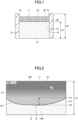
- FIG. 1 is a cross-sectional view illustrating a first embodiment of a method of coloring a dental block
- FIG. 2 is a view illustrating a side surface of the dental block colored in the first embodiment.
- the method of coloring the dental block according to the first embodiment is to penetrate a coloring liquid CL into a dental block 10.
- a dental block also referred to as a blank, is a dental material used in an application such as a dental prosthesis.
- the dental block is a molded body obtained by compressing a ceramic powder into a mold, or a temporarily fired body obtained by temporarily firing (for example, heating in a range of 600°C to 1500°C) the molded body.
- the temporarily fired body is a state in which the ceramic powder particles are temporarily adhered to each other, and the particles have a continuous porous structure through which a coloring liquid described later can penetrate.
- the dental block is cut by computer-aided design/computer-aided manufacturing (CAD/CAM) and the like to be formed into a dental prosthesis, and if necessary, the dental block is fired (for example, heating in a range from 1100°C to 2100°C) after cutting.
- CAD/CAM computer-aided design/computer-aided manufacturing
- the ceramics also include glass containing silicate, borosilicate, aluminosilicate, phosphate, fluorophosphate, or the like and glass ceramics thereof; zirconia; alumina; feldspar; leucite; sanidine; spinel; mica; apatite; zircon; or mixtures thereof.
- the dental block to be colored may be colored in a form of either a molded body (molded body before temporary firing) or a temporary fired body (molded body after temporary firing).
- the coloring of the dental block is preferably performed after temporary firing of the molded body but before fully firing the molded body from the viewpoint of blending the coloring with the dental block.
- the first embodiment includes a dental block 10, a covering material 20, and a coloring liquid CL.
- the dental block 10 includes a top surface 11, a bottom surface 12, and a side surface 13.
- the top surface 11 is an upper surface in the height direction (gravity direction), and the bottom surface 12 is a lower surface in the height direction.
- the side surface 13 has four rectangular surfaces if the shape of the dental block 10 is a rectangular prism shape, and one curved surface if the shape is a cylindrical shape.
- the dental block 10 has a height H1 in the height direction.
- the covering material 20 is a member to cover the side surface 13 of the dental block 10 when the dental block 10 is colored. At least a part of the side surface 13 of the dental block 10 is covered with the covering material 20 over the entire circumference. In the first embodiment, the entire side surface 13 of the dental block 10 is covered with the covering material 20 in a state in which the top surface 11 and the bottom surface 12 of the dental block 10 are exposed (a state in which the top surface and the bottom surface are exposed).
- the covering material 20 has a height H2 in the height direction.
- the height H2 of the covering material 20 is higher than the height H1 of the dental block 10.
- the shape of the covering material 20 is not particularly limited.
- the shape of the dental block 10 is a rectangular prism shape
- the shape of the covering material 20 is a hollow rectangular prism shape with both ends open.
- the shape of the dental block 10 is a cylindrical shape
- the shape of the covering material 20 is a hollow cylindrical shape with both ends open.
- the material of the covering material 20 is not particularly limited, but for example, silicone rubber, resin, wax, and the like. It should be noted that the covering material 20 is preferably a flexible material in that adhesion with the dental block 10 is enhanced when covering the side surface 13 of the dental block 10, and further, silicone rubber or the like is preferable among the flexible materials from the viewpoint of chemical resistance against the coloring liquid CL.
- the coloring liquid CL includes a dye and a liquid.
- the dye is not particularly limited. Examples of the dye include iron chloride, erbium chloride, and the like.
- the liquid is not particularly limited.
- Examples of the liquid include water, polyethylene glycol, and the like.
- the coloring liquid CL penetrates from the top surface 11 or bottom surface 12 of the dental block 10.
- the coloring liquid CL penetrates from the top surface 11 of the dental block 10.
- the covering material 20 is brought into close contact with the side surface 13 of the dental block 10 in a state in which the covering material 20 projects upward from the top surface 11 of the dental block 10, thereby constituting a wall 21 and forming a liquid pool LP in the space formed by the top surface 11 of the dental block 10 and the covering material 20.
- the coloring liquid CL is pooled in the liquid pool LP, the coloring liquid CL penetrates into the dental block 10 from the top surface 11 ( FIG. 1 ).
- a colored region 10A close to the top surface 11 of the dental block 10 and a non-colored region (non-colored region) 10B close to the bottom surface 12 of the dental block 10 are formed.
- a boundary surface PL between the colored region 10A and the non-colored region 10B constitutes a curved shape whose cross-sectional shape of the dental block 10 becomes convex towards the bottom surface 12. That is, the boundary surface PL constitutes a curved surface.
- the boundary surface PL is called a curved surface or a colored surface, and the cross-section of the curved surface of the boundary surface PL may be called a curved line.
- the distance from the top surface 11 of the dental block 10 to the curved surface (curved line of the cross-section) of the boundary surface PL is longer at a boundary P2 close to a center 15 of the dental block 10 than at a boundary P1 close to the side surface 13 of the dental block 10. That is, the curved surface (curved line of the cross-section) of the boundary surface PL is formed such that the distance D between the boundary P1 close to the side surface 13 and the boundary P2 close to the center 15 of the dental block 10 increases from the side surface 13 of the block 10 toward the center 15.
- the side surface 13 (all of the side surface 13 in FIG. 1 ) is covered with the covering material 20 in a state in which the top surface 11 and the bottom surface 12 are exposed, and the coloring liquid CL penetrates from the top surface 11.
- the distance D between the boundary P1 close to the side surface 13 and the boundary P2 close to the center 15 can be shortened ( FIG. 1 and FIG. 2 ).
- a dental block in which the boundary surface (colored surface) PL between the colored region 10A and the non-colored region 10B does not readily curve can be provided.
- deterioration of aesthetics can be prevented ( FIG. 2 ).
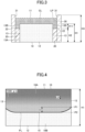
- FIG. 3 is a cross-sectional view illustrating a second embodiment of a method of coloring a dental block
- FIG. 4 is a view illustrating a side surface of the dental block colored in the second embodiment.
- the same reference numerals or the corresponding reference numerals may be indicated to portions common to FIGS. 1 and 2 , and explanations thereof may be omitted.
- a portion 13A close to the bottom surface 12 of the side surface 13 of the dental block 10 is covered with a covering material 20 over the entire circumference, a portion 13B close to the top surface 11 of the side surface 13 is exposed, and the coloring liquid CL penetrates from the top surface 11 and the portion 13B close to the top surface 11 on the side surface 13.
- a portion 13A close to the bottom surface 12 of the side surface 13 of the dental block 10 is covered with a covering material 20 of which a height H2 is lower than a height H1 of the dental block 10, so that the top surface 11 and the portion 13B close to the top surface 11 of the side surface 13 are exposed.
- a guard member 30 in which a height H3 is higher than the height H1 of the dental block 10 covers the outside of the covering material 20 in the circumferential direction by leaving a gap between the portion 13B close to the top surface 11 of the side surface 13 and the guard member 30 ( FIG. 3 ) .
- a liquid pool LP is formed in a space formed by the top surface 11 and the portion 13B close to the top surface 11 of the side surface 13 of the dental block 10, an upper end 22 of the covering material 20, and the guard member 30.
- the portion 13A close to the bottom surface 12 of the side surface 13 of the dental block 10 is covered with the covering material 20 over the entire circumference, and the portion 13B close to the top surface 11 of the side surface 13 is exposed, whereby the coloring liquid CL penetrates from the top surface 11 and the portion 13B close to the top surface 11 of the side surface 13 ( FIG. 3 ).
- the distance D between the boundary P1 close to the side surface 13 and the boundary P2 close to the center 15 can be further shortened, and a dental block in which the boundary surface (colored surface) PL further does not readily curve can be provided.
- a dental block in which the boundary surface (colored surface) PL further does not readily curve can be provided.
- a length H11 of the portion 13B close to the top surface 11 exposed towards the top surface 11 of the side surface 13 in the height direction of the dental block 10 is not limited.
- the length H11 of the portion 13B close to the top surface 11 exposed towards the top surface 11 of the side surface 13 is preferably 40% or less of the total length (height H1) of the side surface 13 in the height direction, more preferably 30% or less, and even more preferably 25% or less.
- the distance D between the boundary P1 close to the side surface 13 and the boundary P2 close to the center 15 can be further shortened ( FIG. 3 and FIG. 4 ).
- the dental block in which the boundary surface (colored surface) PL does not readily curve can be provided.
- the dental block in which the boundary surface (colored surface) PL does not readily curve can be provided.
- further deterioration of aesthetics can be prevented ( FIG. 4 ).
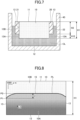
- FIG. 5 is a cross-sectional view illustrating a third embodiment of a method of coloring a dental block.
- FIG. 6 is a view illustrating a side surface of a dental block colored in the third embodiment.
- portions common to FIGS. 1 and 2 may be denoted by the same or corresponding reference numerals, and description thereof may be omitted.
- the entire side surface 13 of the dental block 10 is covered with the covering material 20 in a state in which the top surface 11 and the bottom surface 12 of the dental block 10 are exposed, and the coloring liquid CL penetrates from the bottom surface 12.
- the height H2 of the covering material 20 is substantially the same as the height H1 of the dental block 10, and the entire side surface 13 of the dental block 10 is covered with the covering material 20.
- a container 40 having a circumferential dimension larger than the entire side surface 13 of the dental block 10 being covered with the covering material 20 (hereinafter referred to as a whole covering block) and having a height sufficiently higher than the height H1 of the dental block 10 (the height H2 of the covering material 20) is prepared, and the coloring liquid CL is injected into the container ( FIG. 5 ).
- the entire covering block is immersed in the coloring liquid CL filled in the container 40, and the entire covering block is held so that only the bottom surface 12 of the dental block 10 is exposed to the coloring liquid CL (the top surface 11 is not exposed to the coloring liquid CL).
- the mode of holding the entire covering block is not particularly limited, for example, the entire covering block may be suspended from above in the height direction, and the entire covering block may be fixed to the container 40 with a jig (not shown).
- a colored region 10A close to the bottom surface 12 of the dental block 10 and a non-colored region 10B close to the top surface 11 of the dental block 10 are formed.
- a boundary surface PL between the colored region 10A and the non-colored region 10B constitutes a curved shape whose cross-sectional shape becomes convex towards the top surface 11.
- a curved surface (curved line of the cross-section) of the boundary surface PL is formed so that the distance D between the boundary P1 close to the side surface 13 and the boundary P2 close to the center 15 in the dental block 10 increases from the side surface 13 toward the center 15.
- the entire side surface 13 is covered with the covering material 20 over the entire circumference in a state in which the top surface 11 and the bottom surface 12 are exposed, and the coloring liquid CL penetrates from the bottom surface 12, thereby shortening the distance D between the boundary P1 close to the side surface 13 and the boundary P2 close to the center 15 ( FIG. 5 and FIG. 6 ).
- the dental block in which the boundary surface (colored surface) PL does not readily curve can be provided even when the coloring liquid CL penetrates from the bottom surface 12.
- deterioration of aesthetics can be prevented ( FIG. 6 ).
- FIG. 7 is a cross-sectional view illustrating a fourth embodiment of a method of coloring a dental block
- FIG. 8 is a view illustrating a side surface of the dental block colored in the fourth embodiment.
- portions common to FIGS. 1, 2 , 5, and 6 may be denoted by the same reference numerals or the corresponding reference numerals and the description thereof may be omitted.
- a portion 13B close to the top surface 11 of the side surface 13 of the dental block 10 is covered with a covering material 20 over the entire circumference, a portion 13A close to the bottom surface 12 of the side surface 13 is exposed, and the coloring liquid CL penetrates from the top surface 11 and the portion 13A close to the bottom surface 12 of the side surface 13.
- the portion 13B close to the top surface 11 of the side surface 13 of the dental block 10 is covered with a covering material 20 in which a height H2 is smaller than a height H1 of the dental block 10, so that the portion 13A close to the bottom surface 12 of the side surface 13 of the dental block 10 is exposed.
- the portion 13B close to the top surface 11 of the side surface 13 of the dental block 10 is covered with the covering material 20 (hereinafter referred to as an upper covered block) is immersed in the coloring liquid CL filled in the container 40.
- the upper covered block is held in the container 40 so that only the bottom surface 12 and the portion 13A close to the bottom surface 12 of the side surface 13 of the dental block 10 are exposed to the coloring liquid CL (the top surface 11 is not exposed to the coloring liquid CL).
- the portion 13B close to the top surface 11 of the side surface 13 of the dental block 10 is covered with the covering material 20 over the entire circumference, and the portion 13A close to the bottom surface 12 of the side surface 13 is exposed.
- the coloring liquid CL penetrates from the bottom surface 12 and the portion 13A close to the bottom surface 12 of the side surface 13 ( FIG. 7 and FIG. 8 ).
- a distance D between a boundary P1 close to the side surface 13 of the dental block 10 and a boundary P2 close to the center 15 can be further shortened. Therefore, in the fourth embodiment, a dental block in which the boundary surface (colored surface) PL does not readily curve can be provided. As a result, in the fourth embodiment, further deterioration of aesthetics can be prevented ( FIG. 8 ).
- a height H12 of the portion 13A close to the bottom surface 12 exposed towards the bottom surface 12 of the side surface 13 in the height direction of the dental block 10 is not limited.
- the length H12 of the portion 13A close to the bottom surface 12 exposed towards the bottom surface 12 of the side surface 13 is preferably 40% or less of the total length (height H1) of the side surface 13 in the height direction, more preferably 30% or less, and even more preferably 25% or less.
- the distance D between a boundary P1 close to the side surface 13 and a boundary P2 close to the center 15 can be further shortened ( FIG. 7 and FIG. 8 ).
- a dental block in which the boundary surface (colored surface) PL does not readily curve can be provided.
- the fourth embodiment further deterioration of aesthetics can be prevented ( FIG. 6 ).
- the dental block of this present embodiment is a dental block 10 obtained by the above-described method of coloring the dental block.
- the dental block 10 of the present embodiment is obtained by covering at least a portion of the side surface 13 of the dental block 10 with the covering material 20 over the entire circumference, exposing the top surface 11 and the bottom surface 12, and allowing the coloring liquid to penetrate from the top surface 11 or the bottom surface 12.
- the effect obtained by the method of coloring the dental block described above can also be obtained in the dental block 10.
- the distance D between the boundary P1 close to the side surface 13 and the boundary P2 close to the center 15 can be shortened by covering at least a portion of the side surface 13 with the covering material 20 over the entire circumference in a state in which the top surface 11 and bottom surface 12 are exposed, and allowing the coloring liquid CL to penetrate from the top surface 11 or bottom surface 12.
- the boundary surface (colored surface) PL that does not readily curve can be obtained.
- the deterioration of aesthetics can be prevented.
- a rectangular parallelepiped was carved out of a commercially available zirconia pre-sintered body (Aadva (Registered Trademark) Zirconia Disc EI, manufactured by GC Corporation) for dental cutting using a cutting machine to form a test specimen (dental block) 10.
- a covering material 20 was formed to cover only an entire side surface 13 without blocking (exposing) a bottom surface 12 of the test specimen 10.
- a wall 21 is formed by making an enclosure of the portion covering the side surface 13 of the test specimen 10 higher than the top surface 11 of the test specimen 10, and a liquid pool LP for pooling the coloring liquid CL is formed.
- the coloring liquid CL is poured into the liquid pool LP of the coloring liquid, and the coloring liquid CL is soaked into the inside of the test specimen 10 and colored by holding for 18 hours (See FIG. 1 and FIG. 2 ).
- coloring liquid CL a commercially available coloring liquid for dental ceramics (Aadva (Registered Trademark) Zirconia Color Liquid AZ5, manufactured by GC Corporation) mainly containing water, polyethylene glycol, iron chloride, and erbium chloride was used.
- Adva Registered Trademark
- Zirconia Color Liquid AZ5 Zirconia Color Liquid AZ5, manufactured by GC Corporation
- the colored specimen 10 was sliced to a thickness of 1.5 mm with an automatic precision cutting machine (IsoMet High-Speed Pro, manufactured by BUEHLER) and dried at 60°C for 1 to 3 hours.
- the dried test specimen 10 was baked at 1,500°C for 2 hours to obtain a sintered body.
- the conditions and results of Example 1 are indicated in Table 1.
- the resulting sintered body was photographed with a digital microscope (VHX (Registered Trademark)-J20, manufactured by Keyence Corporation).
- Image analysis software, imageJ was used for image analysis.
- the image was converted to 8-bit grayscale and binarized using the "Default" automatic threshold setting to clarify a color border formed by the coloring liquid penetration and to draw an arc-shaped curve PL, along the color border.
- the distance D between a line (line between the center 15 and P2) parallel to the top surface 11 of the test specimen 10 through the most protruded point of the curved line PL (center 15 of the specimen 10) and the curved line PL and a line parallel to the top surface 11 of the test specimen 10 through the intersection P1 with the side surface 13 of the test specimen 10 was calculated (see FIG. 2 ).
- the ratio P[%] 100 x (D/H1) of the height H1 and the distance D of the test specimen 10 was calculated, and the resulting value was used as an index indicating the degree of curvature of the colored surface (curved line) PL.
- the degree of curvature was determined to be good when the degree of curvature was 12% or less, and poor when the degree of curvature exceeded 12%.
- the test specimen 10 and the sintered body were prepared and evaluated in the same manner as in Example 1 (see FIG. 3 and FIG. 4 ), except that the covering material 20 was formed so as to be exposed to a height of 1/4 (25% of the height H1 of the test specimen 10) from the top surface 11 of the test specimen 10, and a guard member 30 was formed by covering the outside of the covering material 20 with a silicone rubber impression material (Duplicone (Registered Trademark), manufactured by Shofu Co., Ltd.), and a wall 31 was formed by raising a height H3 of the guard member 30 to the height H1 of the top surface 11 of the test specimen, and a liquid pool LP for pooling the colored liquid CL was formed.
- the conditions and results of Example 2 are indicated in Table 1.
- test specimen 10 and the sintered body were prepared and evaluated in the same manner as in Example 2 (see FIG. 3 and FIG. 4 ), except that the exposure of the test specimen 10 in forming the covering material 20 was changed from the top surface 11 to a height of 1/8 (12.5% of the height H1 of the test specimen 10).
- the conditions and results of Example 3 are indicated in Table 1.
- the test specimen 10 and the sintered body were prepared and evaluated in the same manner as in Example 1 (see FIG. 5 and FIG. 6 ), except that the coloring liquid CL was poured into a container 40 having a circumferential dimension larger than that of the covering material 20 covering the entire side surface 13 of the test specimen 10 (the covered block) and a height sufficiently higher than the height H1 of the test specimen 10 (the height H2 of the covering material 20), and the covered block was immersed in the coloring liquid CL and held for 18 hours so that only the bottom surface 12 of the test specimen 10 was exposed to the coloring liquid CL (the top surface 11 was not exposed to the coloring liquid CL).
- the conditions and results of Example 4 are indicated in Table 1.
- the test specimen 10 and sintered body were prepared and evaluated in the same manner as in Example 4 (see FIG. 7 and FIG. 8 ), except that the covering material 20 was formed so as to be exposed from the bottom surface 12 of the test specimen 10 to a height of 1/4 (25% of the height H1 of the test specimen 10), and the covering block was immersed in the coloring liquid CL so that only the bottom surface 12 and a portion 13A of the exposed side surface 13 of the test specimen 10 were exposed to the coloring liquid CL (the top surface 11 was not exposed to the coloring liquid CL).
- the conditions and results of Example 5 are indicated in Table 1.
- test specimen 10 and the sintered body were prepared and evaluated in the same manner as in Example 5, except that the exposure of the test specimen 10 in forming the covering material 20 was changed from the bottom surface 12 to a height of 1/8 (12.5% of the height H1 of the test specimen 10).
- the conditions and results of Example 6 are indicated in Table 1.
- test specimen 10 and the sintered body were prepared and evaluated in the same manner as in Example 5 (see FIG. 7 and FIG. 8 ), except that uniaxial pressure molding was performed at a pressure of 10 MPa using commercially available partially stabilized zirconia powder (Zpex (Registered Trademark), manufactured by Tosoh Corporation) as the raw material powder, and then cold isostatic pressing (CIP) was performed at a pressure of 200 MPa to prepare a rectangular parallelepiped body, the test specimen 10 was degreased by calcination at 450°C for 1 hour, followed by calcination at 1050°C for 2 hours to obtain a pre-sintered body.
- Zpex commercially available partially stabilized zirconia powder
- CIP cold isostatic pressing
- test specimen 10 and the sintered body were prepared and evaluated in the same manner as in Example 1 (see FIG. 9 and FIG. 10 ), except that when forming the covering material 20, the bottom surface 12 of the test specimen 10 was blocked (not exposed), and the covering material 20 (a bottom surface 23 of the covering material) was formed to cover the entire side surface 13 and the bottom surface 12 of the test specimen 10.
- the conditions and results of Comparative Example 1 are indicated in Table 1.
- test specimen 10 and the sintered body were prepared and evaluated in the same manner as in Example 4 except that the test specimen 10 was immersed in the coloring liquid CL without any treatment on the top surface 11, side surface 13, and bottom surface 12 of the test specimen 10 and held for 9 hours (see FIG. 11 and FIG. 12 ).
- the conditions and results of Comparative Example 2 are indicated in Table 1.
- Table 1 indicates that the test piece (dental block), in which at least a part of the side surface 13 of the test specimen 10 is covered with the covering material 20 over the entire circumference, the top surface 11 and the bottom surface 12 are exposed, and the coloring liquid CL penetrates from the top surface 11 or the bottom surface 12, has good curvature and sensory evaluation (Examples 1 to 7).
- test specimen 10 in which the side surface 13 is only covered with the covering material 20 without exposing the bottom surface 12 of the test specimen 10
- the test specimen 10 in which the side surface 13 of the test specimen 10 is not covered with the covering material 20
- have poor curvature and sensory evaluation Comparative Examples 1 and 2.
Landscapes
- Health & Medical Sciences (AREA)
- Oral & Maxillofacial Surgery (AREA)
- General Health & Medical Sciences (AREA)
- Epidemiology (AREA)
- Life Sciences & Earth Sciences (AREA)
- Animal Behavior & Ethology (AREA)
- Public Health (AREA)
- Veterinary Medicine (AREA)
- Dentistry (AREA)
- Chemical & Material Sciences (AREA)
- Engineering & Computer Science (AREA)
- Ceramic Engineering (AREA)
- Plastic & Reconstructive Surgery (AREA)
- Dental Prosthetics (AREA)
- Dental Tools And Instruments Or Auxiliary Dental Instruments (AREA)
Abstract
Description
- The present invention relates to a method of coloring a dental block, and the dental block.
- A dental block is composed of a molded article of ceramic materials, and a dental prosthesis having a desired shape can be obtained by cutting the molded article by a technology such as CAD/CAM (for example, Patent Document 1) and the like.
- In recent years, as a dental block, for the purpose of imparting aesthetics to the dental prosthesis, a coloring block in which a block material is colored with a dye in advance and a gradation block in which a gradient (gradation) is added to the coloring block have been developed (for example,
FIG. 10 , Patent Document 2). -
- [Patent document 1]
Japanese Patent Application Laid-Open No. 2021-115274 - [Patent document 2]
U.S. Patent Application Publication No. 2019/0233340 - However, in the conventional dental block, the colored surface tends to be curved, and the desired aesthetics cannot be obtained.
- The present invention is to provide a dental block in which a colored surface of the dental block does not readily curve.
- In a method of coloring a dental block according to one embodiment of the present invention, the method of coloring a dental block by which a coloring liquid penetrates into the dental block including a top surface, a bottom surface, and a side surface, the method includes covering at least a portion of the side surface with a covering material over an entire circumference of the portion, exposing the top surface and the bottom surface, and causing the coloring liquid to penetrate from the top surface or the bottom surface.
- According to one aspect of the present invention, the present invention is capable of providing a dental block in which a colored surface of the dental block is not easily curved.
-
-
FIG. 1 is a cross-sectional view illustrating a first embodiment of a method of coloring a dental block; -
FIG. 2 is a view illustrating a side surface of the dental block colored in the first embodiment; -
FIG. 3 is a cross-sectional view illustrating a second embodiment of a method of coloring a dental block; -
FIG. 4 is a view illustrating a side surface of the dental block colored in the second embodiment; -
FIG. 5 is a cross-sectional view illustrating a third embodiment of a method of coloring a dental block; -
FIG. 6 is a view illustrating a side surface of the dental block colored in the third embodiment; -
FIG. 7 is a cross-sectional view illustrating a fourth embodiment of a method of coloring a dental block; -
FIG. 8 is a view illustrating a side surface of the dental block colored in the fourth embodiment; -
FIG. 9 is a cross-sectional view illustrating a conventional method of coloring a dental block; -
FIG. 10 is a view illustrating a side surface of the dental block colored in the conventional method; -
FIG. 11 is a cross-sectional view illustrating an embodiment of a comparative example to demonstrate an effect of a covering material; and -
FIG. 12 is a view illustrating a side surface of the dental block colored in the embodiment of the comparative example to demonstrate the effect of the covering material. - Hereinafter, embodiments of the present invention will be described in detail.
-
FIG. 1 is a cross-sectional view illustrating a first embodiment of a method of coloring a dental block, andFIG. 2 is a view illustrating a side surface of the dental block colored in the first embodiment. The method of coloring the dental block according to the first embodiment is to penetrate a coloring liquid CL into adental block 10. - In the present specification, a dental block, also referred to as a blank, is a dental material used in an application such as a dental prosthesis. The dental block is a molded body obtained by compressing a ceramic powder into a mold, or a temporarily fired body obtained by temporarily firing (for example, heating in a range of 600°C to 1500°C) the molded body. The temporarily fired body is a state in which the ceramic powder particles are temporarily adhered to each other, and the particles have a continuous porous structure through which a coloring liquid described later can penetrate.
- The dental block is cut by computer-aided design/computer-aided manufacturing (CAD/CAM) and the like to be formed into a dental prosthesis, and if necessary, the dental block is fired (for example, heating in a range from 1100°C to 2100°C) after cutting.
- The ceramics also include glass containing silicate, borosilicate, aluminosilicate, phosphate, fluorophosphate, or the like and glass ceramics thereof; zirconia; alumina; feldspar; leucite; sanidine; spinel; mica; apatite; zircon; or mixtures thereof.
- The dental block to be colored may be colored in a form of either a molded body (molded body before temporary firing) or a temporary fired body (molded body after temporary firing). However, the coloring of the dental block is preferably performed after temporary firing of the molded body but before fully firing the molded body from the viewpoint of blending the coloring with the dental block.
- As illustrated in
FIG. 1 , the first embodiment includes adental block 10, a coveringmaterial 20, and a coloring liquid CL. - The
dental block 10 includes atop surface 11, abottom surface 12, and aside surface 13. Thetop surface 11 is an upper surface in the height direction (gravity direction), and thebottom surface 12 is a lower surface in the height direction. Theside surface 13 has four rectangular surfaces if the shape of thedental block 10 is a rectangular prism shape, and one curved surface if the shape is a cylindrical shape. Thedental block 10 has a height H1 in the height direction. - The covering
material 20 is a member to cover theside surface 13 of thedental block 10 when thedental block 10 is colored. At least a part of theside surface 13 of thedental block 10 is covered with the coveringmaterial 20 over the entire circumference. In the first embodiment, theentire side surface 13 of thedental block 10 is covered with the coveringmaterial 20 in a state in which thetop surface 11 and thebottom surface 12 of thedental block 10 are exposed (a state in which the top surface and the bottom surface are exposed). - The covering
material 20 has a height H2 in the height direction. In the first embodiment, the height H2 of the coveringmaterial 20 is higher than the height H1 of thedental block 10. - The shape of the covering
material 20 is not particularly limited. For example, if the shape of thedental block 10 is a rectangular prism shape, the shape of the coveringmaterial 20 is a hollow rectangular prism shape with both ends open. If the shape of thedental block 10 is a cylindrical shape, the shape of the coveringmaterial 20 is a hollow cylindrical shape with both ends open. - The material of the covering
material 20 is not particularly limited, but for example, silicone rubber, resin, wax, and the like. It should be noted that the coveringmaterial 20 is preferably a flexible material in that adhesion with thedental block 10 is enhanced when covering theside surface 13 of thedental block 10, and further, silicone rubber or the like is preferable among the flexible materials from the viewpoint of chemical resistance against the coloring liquid CL. - The coloring liquid CL includes a dye and a liquid.
- The dye is not particularly limited. Examples of the dye include iron chloride, erbium chloride, and the like.
- The liquid is not particularly limited. Examples of the liquid include water, polyethylene glycol, and the like.
- The coloring liquid CL penetrates from the
top surface 11 orbottom surface 12 of thedental block 10. - In the first embodiment, the coloring liquid CL penetrates from the
top surface 11 of thedental block 10. Specifically, the coveringmaterial 20 is brought into close contact with theside surface 13 of thedental block 10 in a state in which the coveringmaterial 20 projects upward from thetop surface 11 of thedental block 10, thereby constituting awall 21 and forming a liquid pool LP in the space formed by thetop surface 11 of thedental block 10 and the coveringmaterial 20. When the coloring liquid CL is pooled in the liquid pool LP, the coloring liquid CL penetrates into thedental block 10 from the top surface 11 (FIG. 1 ). - When the coloring liquid CL penetrates into the
dental block 10 from thetop surface 11, as illustrated inFIG. 2 , acolored region 10A close to thetop surface 11 of thedental block 10 and a non-colored region (non-colored region) 10B close to thebottom surface 12 of thedental block 10 are formed. - A boundary surface PL between the
colored region 10A and thenon-colored region 10B constitutes a curved shape whose cross-sectional shape of thedental block 10 becomes convex towards thebottom surface 12. That is, the boundary surface PL constitutes a curved surface. Hereinafter, the boundary surface PL is called a curved surface or a colored surface, and the cross-section of the curved surface of the boundary surface PL may be called a curved line. - The distance from the
top surface 11 of thedental block 10 to the curved surface (curved line of the cross-section) of the boundary surface PL (distance where the coloring liquid CL penetrates) is longer at a boundary P2 close to acenter 15 of thedental block 10 than at a boundary P1 close to theside surface 13 of thedental block 10. That is, the curved surface (curved line of the cross-section) of the boundary surface PL is formed such that the distance D between the boundary P1 close to theside surface 13 and the boundary P2 close to thecenter 15 of thedental block 10 increases from theside surface 13 of theblock 10 toward thecenter 15. - In the first embodiment, as described above, at least a part of the side surface 13 (all of the
side surface 13 inFIG. 1 ) is covered with the coveringmaterial 20 in a state in which thetop surface 11 and thebottom surface 12 are exposed, and the coloring liquid CL penetrates from thetop surface 11. As a result, the distance D between the boundary P1 close to theside surface 13 and the boundary P2 close to thecenter 15 can be shortened (FIG. 1 and FIG. 2 ). - Thus, in the first embodiment, a dental block in which the boundary surface (colored surface) PL between the
colored region 10A and thenon-colored region 10B does not readily curve can be provided. As a result, in the first embodiment, deterioration of aesthetics can be prevented (FIG. 2 ). -
FIG. 3 is a cross-sectional view illustrating a second embodiment of a method of coloring a dental block, andFIG. 4 is a view illustrating a side surface of the dental block colored in the second embodiment. InFIGS. 3 and 4 , the same reference numerals or the corresponding reference numerals may be indicated to portions common toFIGS. 1 and 2 , and explanations thereof may be omitted. - In the second embodiment, a
portion 13A close to thebottom surface 12 of theside surface 13 of thedental block 10 is covered with a coveringmaterial 20 over the entire circumference, aportion 13B close to thetop surface 11 of theside surface 13 is exposed, and the coloring liquid CL penetrates from thetop surface 11 and theportion 13B close to thetop surface 11 on theside surface 13. - Specifically, a
portion 13A close to thebottom surface 12 of theside surface 13 of thedental block 10 is covered with a coveringmaterial 20 of which a height H2 is lower than a height H1 of thedental block 10, so that thetop surface 11 and theportion 13B close to thetop surface 11 of theside surface 13 are exposed. Further, aguard member 30 in which a height H3 is higher than the height H1 of thedental block 10 covers the outside of the coveringmaterial 20 in the circumferential direction by leaving a gap between theportion 13B close to thetop surface 11 of theside surface 13 and the guard member 30 (FIG. 3 ) . - Thus, a liquid pool LP is formed in a space formed by the
top surface 11 and theportion 13B close to thetop surface 11 of theside surface 13 of thedental block 10, anupper end 22 of the coveringmaterial 20, and theguard member 30. When the coloring liquid CL is stored in the liquid pool LP, the coloring liquid CL penetrates into thedental block 10 from thetop surface 11 and theportion 13B close to the top surface of the side surface 13 (FIG. 3 ). - In the second embodiment, as described above, the
portion 13A close to thebottom surface 12 of theside surface 13 of thedental block 10 is covered with the coveringmaterial 20 over the entire circumference, and theportion 13B close to thetop surface 11 of theside surface 13 is exposed, whereby the coloring liquid CL penetrates from thetop surface 11 and theportion 13B close to thetop surface 11 of the side surface 13 (FIG. 3 ). - Thus, in the second embodiment, the distance D between the boundary P1 close to the
side surface 13 and the boundary P2 close to thecenter 15 can be further shortened, and a dental block in which the boundary surface (colored surface) PL further does not readily curve can be provided. As a result, in the second embodiment, further deterioration of aesthetics can be prevented (FIG. 4 ). - Further, in the second embodiment, a length H11 of the
portion 13B close to thetop surface 11 exposed towards thetop surface 11 of theside surface 13 in the height direction of thedental block 10 is not limited. The length H11 of theportion 13B close to thetop surface 11 exposed towards thetop surface 11 of theside surface 13 is preferably 40% or less of the total length (height H1) of theside surface 13 in the height direction, more preferably 30% or less, and even more preferably 25% or less. - In the second embodiment, when the length H11 of the
portion 13B close to thetop surface 11 exposed towards thetop surface 11 of theside surface 13 of thedental block 10 in the height direction is reduced to 40% or less of the total length (height H1) of theside surface 13 in the height direction, the distance D between the boundary P1 close to theside surface 13 and the boundary P2 close to thecenter 15 can be further shortened (FIG. 3 and FIG. 4 ). - Thus, in the second embodiment, the dental block in which the boundary surface (colored surface) PL does not readily curve can be provided. As a result, in the second embodiment, further deterioration of aesthetics can be prevented (
FIG. 4 ). -
FIG. 5 is a cross-sectional view illustrating a third embodiment of a method of coloring a dental block.FIG. 6 is a view illustrating a side surface of a dental block colored in the third embodiment. InFIGS. 5 and 6 , portions common toFIGS. 1 and 2 may be denoted by the same or corresponding reference numerals, and description thereof may be omitted. - In the third embodiment, the
entire side surface 13 of thedental block 10 is covered with the coveringmaterial 20 in a state in which thetop surface 11 and thebottom surface 12 of thedental block 10 are exposed, and the coloring liquid CL penetrates from thebottom surface 12. - Specifically, the height H2 of the covering
material 20 is substantially the same as the height H1 of thedental block 10, and theentire side surface 13 of thedental block 10 is covered with the coveringmaterial 20. On the other hand, acontainer 40 having a circumferential dimension larger than theentire side surface 13 of thedental block 10 being covered with the covering material 20 (hereinafter referred to as a whole covering block) and having a height sufficiently higher than the height H1 of the dental block 10 (the height H2 of the covering material 20) is prepared, and the coloring liquid CL is injected into the container (FIG. 5 ). - The entire covering block is immersed in the coloring liquid CL filled in the
container 40, and the entire covering block is held so that only thebottom surface 12 of thedental block 10 is exposed to the coloring liquid CL (thetop surface 11 is not exposed to the coloring liquid CL). The mode of holding the entire covering block is not particularly limited, for example, the entire covering block may be suspended from above in the height direction, and the entire covering block may be fixed to thecontainer 40 with a jig (not shown). - When the coloring liquid CL penetrates the
dental block 10 from thebottom surface 12, as illustrated inFIG. 6 , acolored region 10A close to thebottom surface 12 of thedental block 10 and anon-colored region 10B close to thetop surface 11 of thedental block 10 are formed. In the third embodiment, a boundary surface PL between thecolored region 10A and thenon-colored region 10B constitutes a curved shape whose cross-sectional shape becomes convex towards thetop surface 11. - Again, in this case, a curved surface (curved line of the cross-section) of the boundary surface PL is formed so that the distance D between the boundary P1 close to the
side surface 13 and the boundary P2 close to thecenter 15 in thedental block 10 increases from theside surface 13 toward thecenter 15. - In the third embodiment, as described above, the
entire side surface 13 is covered with the coveringmaterial 20 over the entire circumference in a state in which thetop surface 11 and thebottom surface 12 are exposed, and the coloring liquid CL penetrates from thebottom surface 12, thereby shortening the distance D between the boundary P1 close to theside surface 13 and the boundary P2 close to the center 15 (FIG. 5 and FIG. 6 ). - Thus, in the third embodiment, the dental block in which the boundary surface (colored surface) PL does not readily curve can be provided even when the coloring liquid CL penetrates from the
bottom surface 12. As a result, in the third embodiment, deterioration of aesthetics can be prevented (FIG. 6 ). -
FIG. 7 is a cross-sectional view illustrating a fourth embodiment of a method of coloring a dental block, andFIG. 8 is a view illustrating a side surface of the dental block colored in the fourth embodiment. InFIGS. 7 and 8 , portions common toFIGS. 1, 2 ,5, and 6 may be denoted by the same reference numerals or the corresponding reference numerals and the description thereof may be omitted. - In the fourth embodiment, a
portion 13B close to thetop surface 11 of theside surface 13 of thedental block 10 is covered with a coveringmaterial 20 over the entire circumference, aportion 13A close to thebottom surface 12 of theside surface 13 is exposed, and the coloring liquid CL penetrates from thetop surface 11 and theportion 13A close to thebottom surface 12 of theside surface 13. - Specifically, the
portion 13B close to thetop surface 11 of theside surface 13 of thedental block 10 is covered with a coveringmaterial 20 in which a height H2 is smaller than a height H1 of thedental block 10, so that theportion 13A close to thebottom surface 12 of theside surface 13 of thedental block 10 is exposed. - The
portion 13B close to thetop surface 11 of theside surface 13 of thedental block 10 is covered with the covering material 20 (hereinafter referred to as an upper covered block) is immersed in the coloring liquid CL filled in thecontainer 40. The upper covered block is held in thecontainer 40 so that only thebottom surface 12 and theportion 13A close to thebottom surface 12 of theside surface 13 of thedental block 10 are exposed to the coloring liquid CL (thetop surface 11 is not exposed to the coloring liquid CL). - In the fourth embodiment, as described above, the
portion 13B close to thetop surface 11 of theside surface 13 of thedental block 10 is covered with the coveringmaterial 20 over the entire circumference, and theportion 13A close to thebottom surface 12 of theside surface 13 is exposed. As a result, the coloring liquid CL penetrates from thebottom surface 12 and theportion 13A close to thebottom surface 12 of the side surface 13 (FIG. 7 and FIG. 8 ). - Thus, even when the coloring liquid CL penetrates from the
bottom surface 12, a distance D between a boundary P1 close to theside surface 13 of thedental block 10 and a boundary P2 close to thecenter 15 can be further shortened. Therefore, in the fourth embodiment, a dental block in which the boundary surface (colored surface) PL does not readily curve can be provided. As a result, in the fourth embodiment, further deterioration of aesthetics can be prevented (FIG. 8 ). - Further, in the fourth embodiment, a height H12 of the
portion 13A close to thebottom surface 12 exposed towards thebottom surface 12 of theside surface 13 in the height direction of thedental block 10 is not limited. The length H12 of theportion 13A close to thebottom surface 12 exposed towards thebottom surface 12 of theside surface 13 is preferably 40% or less of the total length (height H1) of theside surface 13 in the height direction, more preferably 30% or less, and even more preferably 25% or less. - In the fourth embodiment, when the length H12 of the
portion 13A close to thebottom surface 12 exposed towards thebottom surface 12 of theside surface 13 of thedental block 10 in the height direction is reduced to 40% or less of the total length (height H1) of theside surface 13 in the height direction, the distance D between a boundary P1 close to theside surface 13 and a boundary P2 close to thecenter 15 can be further shortened (FIG. 7 and FIG. 8 ). - Thus, in the fourth embodiment, a dental block in which the boundary surface (colored surface) PL does not readily curve can be provided. As a result, in the fourth embodiment, further deterioration of aesthetics can be prevented (
FIG. 6 ). - The dental block of this present embodiment is a
dental block 10 obtained by the above-described method of coloring the dental block. - That is, the
dental block 10 of the present embodiment is obtained by covering at least a portion of theside surface 13 of thedental block 10 with the coveringmaterial 20 over the entire circumference, exposing thetop surface 11 and thebottom surface 12, and allowing the coloring liquid to penetrate from thetop surface 11 or thebottom surface 12. - Thus, in the
dental block 10 of the present embodiment, the effect obtained by the method of coloring the dental block described above can also be obtained in thedental block 10. - That is, in the
dental block 10 of the present embodiment, as described above, the distance D between the boundary P1 close to theside surface 13 and the boundary P2 close to thecenter 15 can be shortened by covering at least a portion of theside surface 13 with the coveringmaterial 20 over the entire circumference in a state in which thetop surface 11 andbottom surface 12 are exposed, and allowing the coloring liquid CL to penetrate from thetop surface 11 orbottom surface 12. - Thus, in the dental block of the present embodiment, when the coloring liquid CL penetrates from the
top surface 11 orbottom surface 12, the boundary surface (colored surface) PL that does not readily curve can be obtained. As a result, in the dental block of the present embodiment, the deterioration of aesthetics can be prevented. - Hereinafter, the present invention will be described with reference to further examples. Examples and Comparative Examples were evaluated by the following tests.
- A rectangular parallelepiped was carved out of a commercially available zirconia pre-sintered body (Aadva (Registered Trademark) Zirconia Disc EI, manufactured by GC Corporation) for dental cutting using a cutting machine to form a test specimen (dental block) 10. Using a silicone rubber impression material (Duplicone (Registered Trademark), manufactured by Shofu Co., Ltd.), a covering
material 20 was formed to cover only anentire side surface 13 without blocking (exposing) abottom surface 12 of thetest specimen 10. - When forming the covering
material 20, awall 21 is formed by making an enclosure of the portion covering theside surface 13 of thetest specimen 10 higher than thetop surface 11 of thetest specimen 10, and a liquid pool LP for pooling the coloring liquid CL is formed. The coloring liquid CL is poured into the liquid pool LP of the coloring liquid, and the coloring liquid CL is soaked into the inside of thetest specimen 10 and colored by holding for 18 hours (SeeFIG. 1 and FIG. 2 ). - As the coloring liquid CL, a commercially available coloring liquid for dental ceramics (Aadva (Registered Trademark) Zirconia Color Liquid AZ5, manufactured by GC Corporation) mainly containing water, polyethylene glycol, iron chloride, and erbium chloride was used.
- The
colored specimen 10 was sliced to a thickness of 1.5 mm with an automatic precision cutting machine (IsoMet High-Speed Pro, manufactured by BUEHLER) and dried at 60°C for 1 to 3 hours. The driedtest specimen 10 was baked at 1,500°C for 2 hours to obtain a sintered body. The conditions and results of Example 1 are indicated in Table 1. - The resulting sintered body was photographed with a digital microscope (VHX (Registered Trademark)-J20, manufactured by Keyence Corporation). Image analysis software, imageJ, was used for image analysis. The image was converted to 8-bit grayscale and binarized using the "Default" automatic threshold setting to clarify a color border formed by the coloring liquid penetration and to draw an arc-shaped curve PL, along the color border.
- The distance D between a line (line between the
center 15 and P2) parallel to thetop surface 11 of thetest specimen 10 through the most protruded point of the curved line PL (center 15 of the specimen 10) and the curved line PL and a line parallel to thetop surface 11 of thetest specimen 10 through the intersection P1 with theside surface 13 of thetest specimen 10 was calculated (seeFIG. 2 ). The ratio P[%] = 100 x (D/H1) of the height H1 and the distance D of thetest specimen 10 was calculated, and the resulting value was used as an index indicating the degree of curvature of the colored surface (curved line) PL. The degree of curvature was determined to be good when the degree of curvature was 12% or less, and poor when the degree of curvature exceeded 12%. - In addition, whether the degree of curvature of the colored surface (curved line) PL is clinically acceptable or not was visually evaluated at four levels. Number of samples was set to 5 and was evaluated by the following criteria. A rating of 3 or higher was determined as good, and a rating of 2 or lower was determined as poor.
-
- 4: The colored surface is horizontal
- 3: The colored surface is horizontal except for both ends
- 2: The colored surface is curved
- 1: The colored surface is highly curved
- The
test specimen 10 and the sintered body were prepared and evaluated in the same manner as in Example 1 (seeFIG. 3 and FIG. 4 ), except that the coveringmaterial 20 was formed so as to be exposed to a height of 1/4 (25% of the height H1 of the test specimen 10) from thetop surface 11 of thetest specimen 10, and aguard member 30 was formed by covering the outside of the coveringmaterial 20 with a silicone rubber impression material (Duplicone (Registered Trademark), manufactured by Shofu Co., Ltd.), and awall 31 was formed by raising a height H3 of theguard member 30 to the height H1 of thetop surface 11 of the test specimen, and a liquid pool LP for pooling the colored liquid CL was formed. The conditions and results of Example 2 are indicated in Table 1. - The
test specimen 10 and the sintered body were prepared and evaluated in the same manner as in Example 2 (seeFIG. 3 and FIG. 4 ), except that the exposure of thetest specimen 10 in forming the coveringmaterial 20 was changed from thetop surface 11 to a height of 1/8 (12.5% of the height H1 of the test specimen 10). The conditions and results of Example 3 are indicated in Table 1. - The
test specimen 10 and the sintered body were prepared and evaluated in the same manner as in Example 1 (seeFIG. 5 and FIG. 6 ), except that the coloring liquid CL was poured into acontainer 40 having a circumferential dimension larger than that of the coveringmaterial 20 covering theentire side surface 13 of the test specimen 10 (the covered block) and a height sufficiently higher than the height H1 of the test specimen 10 (the height H2 of the covering material 20), and the covered block was immersed in the coloring liquid CL and held for 18 hours so that only thebottom surface 12 of thetest specimen 10 was exposed to the coloring liquid CL (thetop surface 11 was not exposed to the coloring liquid CL). The conditions and results of Example 4 are indicated in Table 1. - The
test specimen 10 and sintered body were prepared and evaluated in the same manner as in Example 4 (seeFIG. 7 and FIG. 8 ), except that the coveringmaterial 20 was formed so as to be exposed from thebottom surface 12 of thetest specimen 10 to a height of 1/4 (25% of the height H1 of the test specimen 10), and the covering block was immersed in the coloring liquid CL so that only thebottom surface 12 and aportion 13A of the exposedside surface 13 of thetest specimen 10 were exposed to the coloring liquid CL (thetop surface 11 was not exposed to the coloring liquid CL). The conditions and results of Example 5 are indicated in Table 1. - The
test specimen 10 and the sintered body were prepared and evaluated in the same manner as in Example 5, except that the exposure of thetest specimen 10 in forming the coveringmaterial 20 was changed from thebottom surface 12 to a height of 1/8 (12.5% of the height H1 of the test specimen 10). The conditions and results of Example 6 are indicated in Table 1. - The
test specimen 10 and the sintered body were prepared and evaluated in the same manner as in Example 5 (seeFIG. 7 and FIG. 8 ), except that uniaxial pressure molding was performed at a pressure of 10 MPa using commercially available partially stabilized zirconia powder (Zpex (Registered Trademark), manufactured by Tosoh Corporation) as the raw material powder, and then cold isostatic pressing (CIP) was performed at a pressure of 200 MPa to prepare a rectangular parallelepiped body, thetest specimen 10 was degreased by calcination at 450°C for 1 hour, followed by calcination at 1050°C for 2 hours to obtain a pre-sintered body. The conditions and results of Example 7 are indicated in Table 1. - The
test specimen 10 and the sintered body were prepared and evaluated in the same manner as in Example 1 (seeFIG. 9 and FIG. 10 ), except that when forming the coveringmaterial 20, thebottom surface 12 of thetest specimen 10 was blocked (not exposed), and the covering material 20 (abottom surface 23 of the covering material) was formed to cover theentire side surface 13 and thebottom surface 12 of thetest specimen 10. The conditions and results of Comparative Example 1 are indicated in Table 1. - The
test specimen 10 and the sintered body were prepared and evaluated in the same manner as in Example 4 except that thetest specimen 10 was immersed in the coloring liquid CL without any treatment on thetop surface 11,side surface 13, andbottom surface 12 of thetest specimen 10 and held for 9 hours (seeFIG. 11 and FIG. 12 ). The conditions and results of Comparative Example 2 are indicated in Table 1.[Table 1] Block Example 1 Example 2 Example 3 Example 4 Example 5 Example 6 Example 7 Comparative Example 1 Comparative Example 2 Conditions Processing Cutting Cutting Cutting Cutting Cutting Cutting Pressure molding Cutting Cutting Portion being covered Side surface Side surface (1/4 exposed from top surface) Side surface (1/8 exposed from top surface) Side surface Side surface (1/4 exposed from bottom surface) Side surface (1/8 exposed from bottom surface) Side surface (1/8 exposed from bottom surface) Side surface + Bottom surface - Portion being immersed Top surface Top surface + a portion of side surface close to the top surface Top surface + a portion of side surface close to the top surface Bottom surface Bottom surface + a portion of side surface close to the bottom surface Bottom surface + a portion of side surface close to the bottom surface Bottom surface + a portion of side surface close to the bottom surface Top surface Bottom surface + a portion of side surface close to the bottom surface Results Degree of curvature 11.5% 7.8% 3.5% 11.0% 8.3% 3.8% 8.5% 12.5% 30.7% Visual sensory evaluation 3 3 4 3 3 4 3 2 1 - Table 1 indicates that the test piece (dental block), in which at least a part of the
side surface 13 of thetest specimen 10 is covered with the coveringmaterial 20 over the entire circumference, thetop surface 11 and thebottom surface 12 are exposed, and the coloring liquid CL penetrates from thetop surface 11 or thebottom surface 12, has good curvature and sensory evaluation (Examples 1 to 7). - In contrast, the
test specimen 10, in which theside surface 13 is only covered with the coveringmaterial 20 without exposing thebottom surface 12 of thetest specimen 10, and thetest specimen 10, in which theside surface 13 of thetest specimen 10 is not covered with the coveringmaterial 20, have poor curvature and sensory evaluation (Comparative Examples 1 and 2). - Although embodiments of the present invention have been described above, the present invention is not limited to specific embodiments, and various variations and modifications can be made within the scope of the invention described in the claims.
- This application claims priority under
Japanese Patent Application No. 2021-162425 filed on September 30, 2021 -
- 10
- Dental block (test specimen)
- 11
- Top surface
- 12
- Bottom surface
- 13
- Side surface
- 20
- Covering material
- 21
- Wall
- 22
- Upper end
- 30
- Guard member
- 31
- Wall
- 40
- Container
- H1, H2, H3, H11, H12
- Height
Claims (8)
- A method of coloring a dental block by which a coloring liquid penetrates into the dental block including a top surface, a bottom surface, and a side surface,
the method comprising:covering at least a portion of the side surface with a covering material over an entire circumference of the portion;exposing the top surface and the bottom surface; andcausing the coloring liquid to penetrate from the top surface or the bottom surface. - The method of coloring the dental block according to claim 1,wherein the entire circumference of a portion of the side surface close to the bottom surface is covered with the covering material, and a portion of the side surface close to the top surface is exposed, andwherein the coloring liquid penetrates from the top surface and the portion of the side surface close to the top surface.
- The method of coloring the dental block according to claim 2,
wherein a length, in a height direction of the dental block, of the portion close to the top surface exposed towards the top surface of the side surface is 40% or less of a total length of the side surface in the height direction. - The method of coloring the dental block according to claim 1,wherein the entire circumference of a portion of the side surface close to the top surface is covered with the covering material, and a portion of the side surface close to the bottom surface is exposed, andwherein the coloring liquid penetrates from the top surface and the portion of the side surface close to the bottom surface.
- The method of coloring the dental block according to claim 4, wherein a length, in a height direction of the dental block, of the portion close to the bottom surface exposed towards the bottom surface of the side surface is 40% or less of a total length of the side surface in the height direction.
- The method of coloring the dental block according to any one of claims 1 to 5, wherein the dental block is composed of a molded body formed after temporary firing the molded body but before fully firing the molded body.
- The method of coloring the dental block according to any one of claims 1 to 6, wherein the covering material is formed of a flexible material.
- A dental block obtained by the method of coloring according to any one of claims 1 to 7.
Applications Claiming Priority (2)
| Application Number | Priority Date | Filing Date | Title |
|---|---|---|---|
| JP2021162425A JP7801543B2 (en) | 2021-09-30 | 2021-09-30 | How to color dental blocks |
| PCT/JP2022/031831 WO2023053789A1 (en) | 2021-09-30 | 2022-08-24 | Method for coloring block for dentistry, and block for dentistry |
Publications (3)
| Publication Number | Publication Date |
|---|---|
| EP4410234A1 true EP4410234A1 (en) | 2024-08-07 |
| EP4410234A4 EP4410234A4 (en) | 2025-10-15 |
| EP4410234B1 EP4410234B1 (en) | 2026-08-05 |
Family
ID=85780600
Family Applications (1)
| Application Number | Title | Priority Date | Filing Date |
|---|---|---|---|
| EP22875661.5A Active EP4410234B1 (en) | 2021-09-30 | 2022-08-24 | Methods for coloring block for dentistry, and block for dentistry |
Country Status (8)
| Country | Link |
|---|---|
| US (1) | US12419726B2 (en) |
| EP (1) | EP4410234B1 (en) |
| JP (1) | JP7801543B2 (en) |
| KR (1) | KR20240063960A (en) |
| CN (1) | CN118043008A (en) |
| AU (1) | AU2022354825B2 (en) |
| CA (1) | CA3233338A1 (en) |
| WO (1) | WO2023053789A1 (en) |
Families Citing this family (1)
| Publication number | Priority date | Publication date | Assignee | Title |
|---|---|---|---|---|
| JP2024045925A (en) * | 2022-09-22 | 2024-04-03 | 株式会社ジーシー | Dental ceramic coloring method and dental ceramic coloring liquid |
Family Cites Families (12)
| Publication number | Priority date | Publication date | Assignee | Title |
|---|---|---|---|---|
| JP2010509336A (en) * | 2006-11-09 | 2010-03-25 | ニューヨーク ユニバーシティ | Method for manufacturing sandwich material, glass / ceramic / glass composite structure, glass / ceramic / glass, medical or dental prosthesis, and glass / zirconia / glass sandwich material |
| EP2968076B1 (en) * | 2013-03-12 | 2016-11-16 | 3M Innovative Properties Company | Fluorescence imparting coloring solution for dental ceramics |
| EP3013278B1 (en) * | 2013-06-24 | 2018-02-21 | WDT-Wolz-Dental-Technik GmbH | Coloring porous ceramic |
| CN104337586A (en) * | 2013-07-26 | 2015-02-11 | 棕茂科技股份有限公司 | Gradient ceramic block for dental mold and its manufacturing method |
| WO2016094154A1 (en) * | 2014-12-11 | 2016-06-16 | 3M Innovative Properties Company | A dental coloring stamp and a method of coloring |
| EP3178462A1 (en) * | 2015-12-07 | 2017-06-14 | WDT-Wolz-Dental-Technik GmbH | Method for producing a polychromatic and/or spatially polychromatic or a monochrome colored ceramic body and device for same |
| JP2018143393A (en) * | 2017-03-03 | 2018-09-20 | 株式会社松風 | Easy coloring dental pre-sintered body |
| EP3275398B1 (en) | 2016-07-29 | 2020-11-04 | Shofu Inc. | Mill blank for dental cad/cam with groove not extending over whole of circumference |
| US10974997B2 (en) * | 2018-01-29 | 2021-04-13 | James R. Glidewell Dental Ceramics, Inc. | Polychromatic zirconia bodies and methods of making the same |
| KR102025312B1 (en) * | 2018-05-15 | 2019-09-25 | 주식회사 그린덴탈 | Coloring method of zirconia block for artificial tooth |
| JP7403153B2 (en) | 2020-01-27 | 2023-12-22 | 株式会社トクヤマデンタル | processing block |
| JP7438822B2 (en) | 2020-03-31 | 2024-02-27 | 日鉄ステンレス株式会社 | Magnetic property analysis method, program and magnetic property analysis device |
-
2021
- 2021-09-30 JP JP2021162425A patent/JP7801543B2/en active Active
-
2022
- 2022-08-24 KR KR1020247012413A patent/KR20240063960A/en active Pending
- 2022-08-24 CA CA3233338A patent/CA3233338A1/en active Pending
- 2022-08-24 CN CN202280064654.3A patent/CN118043008A/en active Pending
- 2022-08-24 US US18/690,861 patent/US12419726B2/en active Active
- 2022-08-24 AU AU2022354825A patent/AU2022354825B2/en active Active
- 2022-08-24 EP EP22875661.5A patent/EP4410234B1/en active Active
- 2022-08-24 WO PCT/JP2022/031831 patent/WO2023053789A1/en not_active Ceased
Also Published As
| Publication number | Publication date |
|---|---|
| US12419726B2 (en) | 2025-09-23 |
| AU2022354825A1 (en) | 2024-04-04 |
| WO2023053789A1 (en) | 2023-04-06 |
| CA3233338A1 (en) | 2023-04-06 |
| EP4410234A4 (en) | 2025-10-15 |
| JP2023051605A (en) | 2023-04-11 |
| AU2022354825B2 (en) | 2025-09-11 |
| KR20240063960A (en) | 2024-05-10 |
| US20240423764A1 (en) | 2024-12-26 |
| JP7801543B2 (en) | 2026-01-19 |
| CN118043008A (en) | 2024-05-14 |
| EP4410234B1 (en) | 2026-08-05 |
Similar Documents
| Publication | Publication Date | Title |
|---|---|---|
| Schriwer et al. | Monolithic zirconia dental crowns. Internal fit, margin quality, fracture mode and load at fracture | |
| Wettstein et al. | Clinical study of the internal gaps of zirconia and metal frameworks for fixed partial dentures | |
| ES2924750T3 (en) | Method for producing a dental restoration | |
| CN109937140B (en) | Multilayer oxide ceramic bodies with consistent sintering behavior | |
| AU2017237361B2 (en) | A method to manufacture a colored blank, and blank | |
| US20240315815A1 (en) | Zirconia mill blank for dental cutting and machining and preparing method thereof, and transparency improving liquid for zirconia mill blank for dental cutting and machining and using method thereof | |
| EP3567017A1 (en) | Dental zirconia blank having multilayer structure different in content of yttria | |
| EP3318218B1 (en) | Dental zirconia blank having high relative density | |
| US12193899B2 (en) | Method of manufacturing a zirconium dioxide green body with color and translucency gradients | |
| EP3575277B1 (en) | Opaque imparting liquid for zirconia | |
| US20210196437A1 (en) | Multi-Coloured Blank For Dental Purposes | |
| US12419726B2 (en) | Method of coloring dental block and dental block | |
| EP4005998A1 (en) | Dental zirconia mill blank for cutting and machining including indium and yttrium | |
| KR102651210B1 (en) | Dental products with improved toughness | |
| US20230303459A1 (en) | FABRICATION OF POLYCHROMATIC/POLYTRANSLUCENT ZIRCONIA BLOCK FROM PRE-SHADED ZrO2 BLOCK BY INFILTRATION | |
| EP4371548B1 (en) | Method for applying an opaque imparting liquid for zirconia | |
| JP2022184793A (en) | Method for sintering dental zirconia sintered body | |
| Talic et al. | Internal Adaptation of Implant‐Supported, Polymer‐Infused Ceramic Crowns Fabricated by Two CAD/CAM Systems | |
| US12194112B2 (en) | Indium-containing translucency improving liquid for dental zirconia calcined body | |
| 김용규 | Preclinical comparative evaluation of zirconia crowns based on manufacturing methods and materials | |
| Alsulami | Influence of the coefficient of thermal expansion mismatch on the bond strength of bi-layered all ceramic system |
Legal Events
| Date | Code | Title | Description |
|---|---|---|---|
| STAA | Information on the status of an ep patent application or granted ep patent |
Free format text: STATUS: THE INTERNATIONAL PUBLICATION HAS BEEN MADE |
|
| PUAI | Public reference made under article 153(3) epc to a published international application that has entered the european phase |
Free format text: ORIGINAL CODE: 0009012 |
|
| STAA | Information on the status of an ep patent application or granted ep patent |
Free format text: STATUS: REQUEST FOR EXAMINATION WAS MADE |
|
| 17P | Request for examination filed |
Effective date: 20240321 |
|
| AK | Designated contracting states |
Kind code of ref document: A1 Designated state(s): AL AT BE BG CH CY CZ DE DK EE ES FI FR GB GR HR HU IE IS IT LI LT LU LV MC MK MT NL NO PL PT RO RS SE SI SK SM TR |
|
| DAV | Request for validation of the european patent (deleted) | ||
| DAX | Request for extension of the european patent (deleted) | ||
| A4 | Supplementary search report drawn up and despatched |
Effective date: 20250915 |
|
| RIC1 | Information provided on ipc code assigned before grant |
Ipc: A61C 13/00 20060101AFI20250909BHEP Ipc: A61C 13/083 20060101ALI20250909BHEP Ipc: A61C 5/70 20170101ALI20250909BHEP |
|
| GRAP | Despatch of communication of intention to grant a patent |
Free format text: ORIGINAL CODE: EPIDOSNIGR1 |
|
| STAA | Information on the status of an ep patent application or granted ep patent |
Free format text: STATUS: GRANT OF PATENT IS INTENDED |
|
| INTG | Intention to grant announced |
Effective date: 20260304 |
|
| GRAS | Grant fee paid |
Free format text: ORIGINAL CODE: EPIDOSNIGR3 |
|
| GRAA | (expected) grant |
Free format text: ORIGINAL CODE: 0009210 |
|
| STAA | Information on the status of an ep patent application or granted ep patent |
Free format text: STATUS: THE PATENT HAS BEEN GRANTED |
|
| P01 | Opt-out of the competence of the unified patent court (upc) registered |
Free format text: CASE NUMBER: UPC_APP_0017684_4410234/2026 Effective date: 20260608 |
|
| AK | Designated contracting states |
Kind code of ref document: B1 Designated state(s): AL AT BE BG CH CY CZ DE DK EE ES FI FR GB GR HR HU IE IS IT LI LT LU LV MC MK MT NL NO PL PT RO RS SE SI SK SM TR |
|
| REG | Reference to a national code |
Ref country code: CH Ref legal event code: F10 Free format text: ST27 STATUS EVENT CODE: U-0-0-F10-F00 (AS PROVIDED BY THE NATIONAL OFFICE) Effective date: 20260805 |
|
| REG | Reference to a national code |
Ref country code: CH Ref legal event code: R17 Free format text: ST27 STATUS EVENT CODE: U-0-0-R10-R17 (AS PROVIDED BY THE NATIONAL OFFICE) Effective date: 20260807 |