EP4410224A2 - Pencil-grip wire driver operated with distally located actuator - Google Patents
Pencil-grip wire driver operated with distally located actuator Download PDFInfo
- Publication number
- EP4410224A2 EP4410224A2 EP24183855.6A EP24183855A EP4410224A2 EP 4410224 A2 EP4410224 A2 EP 4410224A2 EP 24183855 A EP24183855 A EP 24183855A EP 4410224 A2 EP4410224 A2 EP 4410224A2
- Authority
- EP
- European Patent Office
- Prior art keywords
- gripping portion
- handpiece
- actuator
- gripping
- channel
- Prior art date
- Legal status (The legal status is an assumption and is not a legal conclusion. Google has not performed a legal analysis and makes no representation as to the accuracy of the status listed.)
- Granted
Links
Images





Classifications
-
- A—HUMAN NECESSITIES
- A61—MEDICAL OR VETERINARY SCIENCE; HYGIENE
- A61B—DIAGNOSIS; SURGERY; IDENTIFICATION
- A61B17/00—Surgical instruments, devices or methods
- A61B17/56—Surgical instruments or methods for treatment of bones or joints; Devices specially adapted therefor
- A61B17/58—Surgical instruments or methods for treatment of bones or joints; Devices specially adapted therefor for osteosynthesis, e.g. bone plates, screws or setting implements
- A61B17/88—Osteosynthesis instruments; Methods or means for implanting or extracting internal or external fixation devices
- A61B17/8861—Apparatus for manipulating flexible wires or straps
-
- A—HUMAN NECESSITIES
- A61—MEDICAL OR VETERINARY SCIENCE; HYGIENE
- A61B—DIAGNOSIS; SURGERY; IDENTIFICATION
- A61B17/00—Surgical instruments, devices or methods
- A61B17/16—Instruments for performing osteoclasis; Drills or chisels for bones; Trepans
- A61B17/1697—Instruments for performing osteoclasis; Drills or chisels for bones; Trepans specially adapted for wire insertion
-
- A—HUMAN NECESSITIES
- A61—MEDICAL OR VETERINARY SCIENCE; HYGIENE
- A61B—DIAGNOSIS; SURGERY; IDENTIFICATION
- A61B17/00—Surgical instruments, devices or methods
- A61B17/16—Instruments for performing osteoclasis; Drills or chisels for bones; Trepans
- A61B17/1613—Component parts
- A61B17/1622—Drill handpieces
-
- A—HUMAN NECESSITIES
- A61—MEDICAL OR VETERINARY SCIENCE; HYGIENE
- A61B—DIAGNOSIS; SURGERY; IDENTIFICATION
- A61B17/00—Surgical instruments, devices or methods
- A61B17/32—Surgical cutting instruments
- A61B17/320016—Endoscopic cutting instruments, e.g. arthroscopes, resectoscopes
- A61B17/32002—Endoscopic cutting instruments, e.g. arthroscopes, resectoscopes with continuously rotating, oscillating or reciprocating cutting instruments
-
- A—HUMAN NECESSITIES
- A61—MEDICAL OR VETERINARY SCIENCE; HYGIENE
- A61B—DIAGNOSIS; SURGERY; IDENTIFICATION
- A61B17/00—Surgical instruments, devices or methods
- A61B17/16—Instruments for performing osteoclasis; Drills or chisels for bones; Trepans
- A61B17/1613—Component parts
- A61B17/1622—Drill handpieces
- A61B17/1624—Drive mechanisms therefor
-
- A—HUMAN NECESSITIES
- A61—MEDICAL OR VETERINARY SCIENCE; HYGIENE
- A61B—DIAGNOSIS; SURGERY; IDENTIFICATION
- A61B17/00—Surgical instruments, devices or methods
- A61B2017/00367—Details of actuation of instruments, e.g. relations between pushing buttons, or the like, and activation of the tool, working tip, or the like
-
- A—HUMAN NECESSITIES
- A61—MEDICAL OR VETERINARY SCIENCE; HYGIENE
- A61B—DIAGNOSIS; SURGERY; IDENTIFICATION
- A61B17/00—Surgical instruments, devices or methods
- A61B2017/0042—Surgical instruments, devices or methods with special provisions for gripping
-
- A—HUMAN NECESSITIES
- A61—MEDICAL OR VETERINARY SCIENCE; HYGIENE
- A61B—DIAGNOSIS; SURGERY; IDENTIFICATION
- A61B17/00—Surgical instruments, devices or methods
- A61B17/28—Surgical forceps
- A61B17/29—Forceps for use in minimally invasive surgery
- A61B17/2909—Handles
- A61B2017/291—Handles the position of the handle being adjustable with respect to the shaft
Definitions
- the present invention is directed generally to a wire driver for inserting a wire into bone and, more particularly, to a wire driver with a distal actuator and a rotating mechanism.
- Wire drivers are surgical devices that insert wires into bone.
- Pencil-grip wire drivers are devices that are shaped such that the device is typically held like a pencil, using techniques such as the cylindrical grasp, digital grasp, modified tripod grasp, or tripod grasp.
- Pencil-grip wire drivers have an internal mechanism that grips the wire and provides rotary force to the wire. The mechanism to grip and release the wires is controlled by an actuator.
- Existing wire drivers 1 have said actuator 2 located away from its distal end 3, as shown in FIG. 1 , or require a second hand to move such actuator 2, as shown in FIG. 2 .
- actuation of said actuator requires the surgeons to move their fingers from the grasping position or to use a second hand to actuate the actuator, which can be a major inconvenience to the surgeon.
- the present invention is directed to a wire driver with a distal gripping actuator and a rotating mechanism that allows a surgeon to maintain a preferred grip on the wire driver while gripping and releasing a wire extending therethrough.
- the wire driver includes a housing having a proximal end and a distal end.
- the housing has a handpiece extending to the proximal end and the handpiece is connected to a gripping portion, which extends to the distal end.
- a channel extends through the gripping portion and is connected to a gripping mechanism.
- the wire driver also includes a first actuator connected to the distal end of the housing and the gripping mechanism. The first actuator is movable between a relaxed position and a compressed position.
- the present invention is a powered surgical tool.
- the surgical tool includes a housing having a proximal end and a distal end.
- the housing has a handpiece connected to a gripping portion.
- the handpiece extends to the proximal end and the gripping portion extends to the distal end.
- the gripping portion extends along a central longitudinal axis and the handpiece is connected to the gripping portion at an angle relative to the central longitudinal axis.
- the surgical tool also includes a rotating mechanism within the housing. The gripping portion is rotatable about the rotating mechanism relative to the handpiece.
- the actuators identified herein can be actuated by any number of ways consistent with the basic functional concepts thereof (as summarized herein), and can include a squeezing actuation, a flipping actuation, a twisting/turning actuation, a pushing actuation and the like (as should be appreciated by those of skill in the art in conjunction with a review of this disclosure).
- the directions of such actuations can include alternative directions from those discussed and implemented in the examples described herein, e.g., push in the relative distal direction vs. pull in the relative proximal direction, pursuant to appropriate alternative structure to facilitate such alternative movement (as should be appreciated by those of skill in the art in conjunction with a review of this disclosure).
- FIG. 3 is a cross-sectional side view schematic representation of a wire driver 100, according to an embodiment.
- the wire driver 100 comprises a housing 102 having a proximal end 104 and a distal end 106.
- the housing 102 comprises a handpiece 108 extending to the proximal end 104 and a gripping portion 110 extending to the distal end 106.
- the handpiece 108 is connected to the gripping portion 110 at an angle.
- the gripping portion 110 extends along a central longitudinal y - y axis and the handpiece 108 extends proximally from the gripping portion 110 at angle relative to the central longitudinal y - y axis.
- the handpiece 108 is not connected to the gripping portion 110 at an angle, and extends proximally from the gripping portion 110 along the y -- y axis or along an axis that is at least substantially parallel to the y -- y axis (see, e.g., FIG. 5-7 , discussed below).
- the handpiece 108 comprises a drive mechanism 112 therein such that the wire driver 100 is used as a standalone device.
- the wire driver 100 may also be an attachment to another device.
- the drive mechanism 112 is a motor and a gear assembly.
- the motor 114 rotates a first gear 116 of the gear assembly 118 and drives the gripping portion 110.
- the drive mechanism 112 may be battery powered, pneumatic, or connected to an external power source (e.g., via a cord).
- the gripping portion 110 comprises a first end 120 and a second end 122 with a channel 124 extending therethrough.
- the gear assembly 118 extends into the first end 120 of the gripping portion 110.
- the first end 120 of the gripping portion 110 comprises a second gear 126 of the gear assembly 118.
- the second gear 126 engages the first gear 116, which is powered by the motor 114. Power from the motor 114 rotates the gear assembly 118, causing rotation of the channel 124 and the wire (not shown) therein.
- the drive mechanism 112 performs the rotation of the channel 124 (and the wire (not shown)) when a driving actuator 138 is triggered.
- the driving actuator 138 is connected to the handpiece 108 of the wire driver 100. Specifically, in the depicted embodiment, the driving actuator 138 is attached at the proximal end 104 of the wire driver 100.
- the driving actuator 138 shown in FIG. 3 is a long curved arm connected to the handpiece 108 via a biased connector 142, such as a spring lever, for example.
- the driving actuator 138 is curved such that a distal portion 146 of the driving actuator 138 extends at least partially around and/or over the gripping portion 110 of the housing 102.
- a proximal portion 144 of the driving actuator 138 extends proximally relative to the biased connector 142 so that the driving actuator 138 can be easily accessed at any point along the housing 102, providing numerous grip options for the user.
- the gripping portion 110 of the wire driver 100 additionally comprises a spring assembly 128 and a distal collet 130.
- the channel 124 in the gripping portion 110 extends through the spring assembly 128 and the distal collet 130, as shown.
- the channel 124 comprises a gripping mechanism 132.
- the gripping mechanism 132 is a spindle 134 with a gripper 136 (e.g., three (or more) prong-like pieces capable of compression toward each other).
- the purpose of the gripping mechanism 132 is to grip and release a wire (not shown) extending through the channel 124.
- the gripping and release actions are performed on the wire (not shown) by a gripping actuator 140.
- the gripping actuator 140 is a collet lever on a side 148 of the gripping portion 110.
- the gripping actuator 140 is connected to the collet 130.
- the gripping actuator 140 In a relaxed position, as shown in FIGs. 3 and 4 , the gripping actuator 140 is biased (by the spring assembly 128) in the distal direction.
- the gripping actuator 140 In other words, when the spring assembly 128 is in a relaxed state, the gripping actuator 140 is biased in the distal direction and causes the gripping mechanism 132 to be in the closed position and gripping the wire (not shown).
- the user pulls the gripping actuator 140 in the proximal direction, which draws the collet 130 proximally against the spring assembly 128.
- the gripping mechanism 132 (including the gripper 136) releases the wire (not shown) within the channel 124, placing the wire driver 100 in the compressed position (not shown).
- FIGs. 5-7 there are shown various views schematic representation of a wire driver 100, according to an alternative embodiment.
- a central longitudinal y - y axis extends through the gripping portion 110, as shown in the embodiment in FIGs. 3-4 .
- the handpiece 108 does not extend from the gripping portion 110 at an angle relative to the central longitudinal y - y axis.
- the handpiece 108 extends along a central longitudinal x - x axis, which is approximately parallel to the central longitudinal y - y axis.
- a channel 124 also extends through and from a first end 120 of the gripping portion 110 to a second end 122 of the gripping portion 110.
- the channel 124 extends along or parallel to the central longitudinal y - y axis.
- the gripping portion 110 is slightly offset from the handpiece 108 such that the first end 120 of the gripping portion 110, has a clearance amount relative to the handpiece 108.
- the channel 124 extending through the gripping portion 110 bypasses the motor 114 in the handpiece 108, as shown in FIG. 7 .
- the channel 124 extends and is connected to a slot 150 through at least a portion of a bottom surface 152 of the handpiece 108, as shown in FIG. 6 .
- the slot 150 extends toward the proximal end 104 of the housing 102.
- the handpiece 108 comprises a sliding mechanism 154 for selectively permitting or inhibiting operation of the drive mechanism 112 when the driving actuator 138 is engaged (e.g., depressed).
- a track (or channel) 156 extends through at a least a portion of a side surface 158 of the handpiece 108.
- the handpiece 108 comprises a slider 160 sized and configured to slide distally and proximally along the track 156 in the handpiece 108. The user can thus move the slider 160 from a locked position to an unlocked position. In the unlocked position, the slider 160 permits operation of the drive mechanism 112.
- the driving actuator 138 is engaged and in the locked position, the slider 160 inhibits operation of the drive mechanism 112 when the driving actuator 138 is engaged.
- FIGs. 8-14 there are shown various views schematic representations of a wire driver 100, according to yet another embodiment.
- the free end portion of the gripping actuator 140 faces away from the driving actuator 138, and is pulled in the proximal direction to be actuated.
- FIG. 8 shows a side view schematic representation of the wire driver 100.
- the wire driver 100 comprises a rotating (or indexing) mechanism 166 ( FIG. 15 ) allowing for the wire (not shown) to be in a different plane relative to the planar axis of the handpiece 108.
- the handpiece 108 extends along plane z - z.
- the gripping portion 110 also extends along plane z - z.
- FIG. 15 An embodiment of the rotating (indexing) mechanism 166 is shown in FIG. 15 .
- the gripping portion 110 rotates about the rotating (indexing) mechanism 166 relative to the handpiece 108.
- the rotating (indexing) mechanism 166 also maintains the connection between the gripping portion 110 and the handpiece 108 as the gripping portion 110 rotates.
- the rotating (indexing) mechanism 166 includes a ring 168 that extends around both the gripping portion 110 and the handpiece 108, holding them together.
- the rotating (indexing) mechanism 166 also includes one or more balls (or spheres) 170 between the ring 168 and both the gripping portion 110 and handpiece 108.
- the balls 170 rotate as the gripping portion 110 rotates around the handpiece 108.
- the balls 170 provide allow for movement of the gripping portion 110 about the handpiece 108, but the ring 168 limits the movement such that the gripping portion 110 does not become disconnected from the handpiece 108.
- FIG. 9 shows a perspective view schematic representation of the wire driver 100.
- the driving actuator 138 comprises an opening 162 such that the wire (not shown) may extend therethrough.
- the wire 164 extends through the opening 162 in the driving actuator 138 and through the gripping portion 110, as shown in FIG. 10 .
- the opening 162 in the driving actuator 138 is aligned with the gripping portion 110 such that the wire 164 may extend through both the opening 162 and the gripping portion 110.
- the driving actuator 138 is in the same plane (along plane z - z) as the handpiece 108 and the gripping portion 110.
- FIGs. 12-14 show various views schematic representations of the wire driver 100 in a second configuration.
- the gripping portion 110 is rotated about the rotating mechanism (not shown) out of plane z - z.
- the gripping portion 110 has been rotated 90° relative to plane z - z.
- the gripping portion 110 may be rotatable to any angle relative to the plane z - z.
- the rotating mechanism (not shown) allows the flexibility of the user (e.g., surgeon) to grip the handpiece 108 according to his or her personal preference and for greater comfort. Further, if the user selects an overhand grip to hold the wire driver 100, as shown in FIGs.
- the wire 164 can be hazardous because it is directly in line with the palm of the user's hand. As surgical wires 164 typically have pointed tips at both ends, the proximal tip can puncture the surgeon's glove and/or cause injury. Thus, the rotating mechanism (not shown) also serves as a safety feature of the wire driver 100 in FIGs. 8-14 .
- a method or device that "comprises”, “has”, “includes” or “contains” one or more steps or elements possesses those one or more features, but is not limited to possessing only those one or more features.
- a device or structure that is configured in a certain way is configured in at least that way, but may also be configured in ways that are not listed.
- a wire driver comprising:
- the present application further discloses a wire driver according to the above first aspect, wherein in the relaxed position, the gripping mechanism is closed.
- the present application further discloses a wire driver according to the above first aspect, further comprising a drive mechanism positioned within the handpiece and connected to the channel, wherein the drive mechanism is configured to rotate the channel when actuated by a second actuator connected to the handpiece.
- the present application further discloses a wire driver according to the above further aspect, wherein the second actuator extends along the handpiece and at least a portion of the gripping portion.
- the present application further discloses a wire driver according to the above first aspect, wherein the gripping portion extends along a first central longitudinal axis.
- the present application further discloses a wire driver according to the above third aspect, wherein the handpiece is connected to the gripping portion at an angle relative to the first central longitudinal axis.
- the present application further discloses a wire driver according to the above third aspect, wherein the handpiece extends along a second central longitudinal axis, which is parallel to the first central longitudinal axis.
- the present application further discloses a wire driver according to the above first aspect, further comprising a spring assembly within the gripping portion, the spring assembly connected to the gripping mechanism.
- the present application further discloses a wire driver according to the above fourth aspect, wherein when the first actuator is in the compressed position, the spring assembly is compressed and the gripping mechanism is in an open position.
- the present application further discloses a wire driver according to the above first aspect, wherein the first actuator is movable between a relaxed position and a compressed position, characterized in that the gripping portion is rotatable about the rotating mechanism relative to the handpiece.
Landscapes
- Health & Medical Sciences (AREA)
- Life Sciences & Earth Sciences (AREA)
- Surgery (AREA)
- Orthopedic Medicine & Surgery (AREA)
- Medical Informatics (AREA)
- General Health & Medical Sciences (AREA)
- Biomedical Technology (AREA)
- Heart & Thoracic Surgery (AREA)
- Nuclear Medicine, Radiotherapy & Molecular Imaging (AREA)
- Molecular Biology (AREA)
- Animal Behavior & Ethology (AREA)
- Engineering & Computer Science (AREA)
- Public Health (AREA)
- Veterinary Medicine (AREA)
- Dentistry (AREA)
- Oral & Maxillofacial Surgery (AREA)
- Surgical Instruments (AREA)
- Dental Tools And Instruments Or Auxiliary Dental Instruments (AREA)
- Mechanical Control Devices (AREA)
Abstract
Description
- This application claims priority to
U.S. Provisional Patent Application Serial No. 62/654,618, filed on April 9, 2018 - The present invention is directed generally to a wire driver for inserting a wire into bone and, more particularly, to a wire driver with a distal actuator and a rotating mechanism.
- Wire drivers are surgical devices that insert wires into bone. Pencil-grip wire drivers are devices that are shaped such that the device is typically held like a pencil, using techniques such as the cylindrical grasp, digital grasp, modified tripod grasp, or tripod grasp. Pencil-grip wire drivers have an internal mechanism that grips the wire and provides rotary force to the wire. The mechanism to grip and release the wires is controlled by an actuator. Existing wire drivers 1 have said
actuator 2 located away from itsdistal end 3, as shown inFIG. 1 , or require a second hand to movesuch actuator 2, as shown inFIG. 2 . Thus, in order to grip or release the wire, actuation of said actuator requires the surgeons to move their fingers from the grasping position or to use a second hand to actuate the actuator, which can be a major inconvenience to the surgeon. - Therefore, there is a need for a wire driver with a distal gripping actuator and a rotating mechanism that allows a surgeon to maintain a preferred grip on the wire driver while gripping and releasing a wire extending therethrough.
- Description of the Related Art Section Disclaimer: To the extent that specific patents/publications/products are discussed above in this Description of the Related Art Section or elsewhere in this disclosure, these discussions should not be taken as an admission that the discussed patents/publications/products are prior art for patent law purposes. For example, some or all of the discussed patents/publications/products may not be sufficiently early in time, may not reflect subject matter developed early enough in time and/or may not be sufficiently enabling so as to amount to prior art for patent law purposes. To the extent that specific patents/publications/products are discussed above in this Description of the Related Art Section and/or throughout the application, the descriptions/disclosures of which are all hereby incorporated by reference into this document in their respective entirety(ies).
- The present invention is directed to a wire driver with a distal gripping actuator and a rotating mechanism that allows a surgeon to maintain a preferred grip on the wire driver while gripping and releasing a wire extending therethrough. According to one aspect, the wire driver includes a housing having a proximal end and a distal end. The housing has a handpiece extending to the proximal end and the handpiece is connected to a gripping portion, which extends to the distal end. A channel extends through the gripping portion and is connected to a gripping mechanism. The wire driver also includes a first actuator connected to the distal end of the housing and the gripping mechanism. The first actuator is movable between a relaxed position and a compressed position.
- According to another aspect, the present invention is a powered surgical tool. The surgical tool includes a housing having a proximal end and a distal end. The housing has a handpiece connected to a gripping portion. The handpiece extends to the proximal end and the gripping portion extends to the distal end. The gripping portion extends along a central longitudinal axis and the handpiece is connected to the gripping portion at an angle relative to the central longitudinal axis. The surgical tool also includes a rotating mechanism within the housing. The gripping portion is rotatable about the rotating mechanism relative to the handpiece.
- According to an embodiment, the actuators identified herein can be actuated by any number of ways consistent with the basic functional concepts thereof (as summarized herein), and can include a squeezing actuation, a flipping actuation, a twisting/turning actuation, a pushing actuation and the like (as should be appreciated by those of skill in the art in conjunction with a review of this disclosure). The directions of such actuations can include alternative directions from those discussed and implemented in the examples described herein, e.g., push in the relative distal direction vs. pull in the relative proximal direction, pursuant to appropriate alternative structure to facilitate such alternative movement (as should be appreciated by those of skill in the art in conjunction with a review of this disclosure).
- These and other aspects of the invention will be apparent from and elucidated with reference to the embodiment(s) described hereinafter.
- One or more aspects of the present invention are particularly pointed out and distinctly claimed as examples in the claims at the conclusion of the specification. The foregoing and other objects, features, and advantages of the invention are apparent from the following description taken in conjunction with the accompanying drawings in which:
-
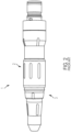
FIG. 1 is a wire driver of the prior art; -
FIG. 2 is another wire driver of the prior art; -
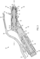
FIG. 3 is a cross-sectional side view schematic representation of a wire driver, according to an embodiment; -
FIG. 4 is a side view schematic representation of the wire driver, according to an embodiment; -
FIG. 5 is a side view schematic representation of a wire driver, according to an alternative embodiment; -
FIG. 6 is a bottom view schematic representation of the wire driver ofFIG. 5 ; -
FIG. 7 cross-section side view schematic representation of the wire driver ofFIG. 5 ; -
FIG. 8 is a side view schematic representation of a wire driver, according to another embodiment; -
FIG. 9 is a perspective view schematic representation of the wire driver ofFIG. 8 ; -
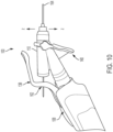
FIG. 10 is a side view schematic representation of the wire driver ofFIG. 8 in a first configuration with a wire extending therethrough; -
FIG. 11 is a top view schematic representation of the wire driver ofFIG. 10 ; -
FIG. 12 is a side view schematic representation of the wire driver ofFIG. 8 in a second configuration with a wire extending therethrough; -
FIG. 13 is a top view schematic representation of the wire driver ofFIG. 11 ; -
FIG. 14 is another top view schematic representation of the wire driver ofFIG. 11 ; -
FIG. 15 is a cross-sectional side view schematic representation of the wire driver ofFIG. 8 . - Aspects of the present invention and certain features, advantages, and details thereof, are explained more fully below with reference to the non-limiting examples illustrated in the accompanying drawings. Descriptions of well-known structures may be omitted so as not to unnecessarily obscure the invention in detail. It should be understood, however, that the detailed description and the specific non-limiting examples, while indicating aspects of the invention, are given by way of illustration only, and are not by way of limitation. Various substitutions, modifications, additions, and/or arrangements, within the spirit and/or scope of the underlying inventive concepts will be apparent to those skilled in the art from this disclosure.
- Referring now to the figures, wherein like reference numerals refer to like parts throughout,
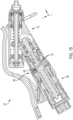
FIG. 3 is a cross-sectional side view schematic representation of awire driver 100, according to an embodiment. Thewire driver 100 comprises ahousing 102 having aproximal end 104 and adistal end 106. In the depicted embodiment, thehousing 102 comprises ahandpiece 108 extending to theproximal end 104 and agripping portion 110 extending to thedistal end 106. Thehandpiece 108 is connected to thegripping portion 110 at an angle. Specifically, thegripping portion 110 extends along a central longitudinal y - y axis and thehandpiece 108 extends proximally from thegripping portion 110 at angle relative to the central longitudinal y - y axis. According to an alternative embodiment, thehandpiece 108 is not connected to thegripping portion 110 at an angle, and extends proximally from thegripping portion 110 along the y -- y axis or along an axis that is at least substantially parallel to the y -- y axis (see, e.g.,FIG. 5-7 , discussed below). - Still referring to
FIG. 3 , thehandpiece 108 comprises adrive mechanism 112 therein such that thewire driver 100 is used as a standalone device. However, thewire driver 100 may also be an attachment to another device. In the depicted embodiment, thedrive mechanism 112 is a motor and a gear assembly. InFIG. 3 , themotor 114 rotates afirst gear 116 of thegear assembly 118 and drives the grippingportion 110. In alternative embodiments, thedrive mechanism 112 may be battery powered, pneumatic, or connected to an external power source (e.g., via a cord). - Still referring to
FIG. 3 , the grippingportion 110 comprises afirst end 120 and asecond end 122 with achannel 124 extending therethrough. Thegear assembly 118 extends into thefirst end 120 of thegripping portion 110. In the depicted embodiment, thefirst end 120 of thegripping portion 110 comprises asecond gear 126 of thegear assembly 118. Thesecond gear 126 engages thefirst gear 116, which is powered by themotor 114. Power from themotor 114 rotates thegear assembly 118, causing rotation of thechannel 124 and the wire (not shown) therein. Thedrive mechanism 112 performs the rotation of the channel 124 (and the wire (not shown)) when a drivingactuator 138 is triggered. - As shown in
FIG. 3 , the drivingactuator 138 is connected to thehandpiece 108 of thewire driver 100. Specifically, in the depicted embodiment, the drivingactuator 138 is attached at theproximal end 104 of thewire driver 100. The drivingactuator 138 shown inFIG. 3 is a long curved arm connected to thehandpiece 108 via abiased connector 142, such as a spring lever, for example. In the depicted embodiment, the drivingactuator 138 is curved such that adistal portion 146 of the drivingactuator 138 extends at least partially around and/or over the grippingportion 110 of thehousing 102. Aproximal portion 144 of the drivingactuator 138 extends proximally relative to thebiased connector 142 so that the drivingactuator 138 can be easily accessed at any point along thehousing 102, providing numerous grip options for the user. - With reference still to
FIG. 3 , the grippingportion 110 of thewire driver 100 additionally comprises aspring assembly 128 and adistal collet 130. Thechannel 124 in thegripping portion 110 extends through thespring assembly 128 and thedistal collet 130, as shown. Thechannel 124 comprises agripping mechanism 132. In the depicted embodiment, thegripping mechanism 132 is aspindle 134 with a gripper 136 (e.g., three (or more) prong-like pieces capable of compression toward each other). The purpose of thegripping mechanism 132 is to grip and release a wire (not shown) extending through thechannel 124. The gripping and release actions are performed on the wire (not shown) by agripping actuator 140. As shown inFIG. 4 , the grippingactuator 140 is a collet lever on aside 148 of thegripping portion 110. - In the embodiment shown in
FIG. 3 , the grippingactuator 140 is connected to thecollet 130. In a relaxed position, as shown inFIGs. 3 and4 , the grippingactuator 140 is biased (by the spring assembly 128) in the distal direction. In other words, when thespring assembly 128 is in a relaxed state, the grippingactuator 140 is biased in the distal direction and causes thegripping mechanism 132 to be in the closed position and gripping the wire (not shown). To engage thegripping actuator 140, the user pulls thegripping actuator 140 in the proximal direction, which draws thecollet 130 proximally against thespring assembly 128. As thecollet 130 is pulled proximally by the grippingactuator 140, the gripping mechanism 132 (including the gripper 136) releases the wire (not shown) within thechannel 124, placing thewire driver 100 in the compressed position (not shown). - Turning now to
FIGs. 5-7 , there are shown various views schematic representation of awire driver 100, according to an alternative embodiment. In the depicted embodiment, a central longitudinal y - y axis extends through the grippingportion 110, as shown in the embodiment inFIGs. 3-4 . However, in the embodiment inFIGs. 5-7 , thehandpiece 108 does not extend from the grippingportion 110 at an angle relative to the central longitudinal y - y axis. As shown inFIG. 5 , thehandpiece 108 extends along a central longitudinal x - x axis, which is approximately parallel to the central longitudinal y - y axis. - In the embodiment of the
wire driver 100 depicted inFIG. 7 , achannel 124 also extends through and from afirst end 120 of thegripping portion 110 to asecond end 122 of thegripping portion 110. InFIG. 7 , thechannel 124 extends along or parallel to the central longitudinal y - y axis. Further, the grippingportion 110 is slightly offset from thehandpiece 108 such that thefirst end 120 of thegripping portion 110, has a clearance amount relative to thehandpiece 108. In particular, thechannel 124 extending through the grippingportion 110 bypasses themotor 114 in thehandpiece 108, as shown inFIG. 7 . However, thechannel 124 extends and is connected to aslot 150 through at least a portion of abottom surface 152 of thehandpiece 108, as shown inFIG. 6 . In the depicted embodiment, theslot 150 extends toward theproximal end 104 of thehousing 102. - As also shown in
FIGs. 5 and7 , thehandpiece 108 comprises a slidingmechanism 154 for selectively permitting or inhibiting operation of thedrive mechanism 112 when the drivingactuator 138 is engaged (e.g., depressed). As shown inFIG. 5 , a track (or channel) 156 extends through at a least a portion of aside surface 158 of thehandpiece 108. As shown inFIG. 5 , thehandpiece 108 comprises aslider 160 sized and configured to slide distally and proximally along thetrack 156 in thehandpiece 108. The user can thus move theslider 160 from a locked position to an unlocked position. In the unlocked position, theslider 160 permits operation of thedrive mechanism 112. When the drivingactuator 138 is engaged and in the locked position, theslider 160 inhibits operation of thedrive mechanism 112 when the drivingactuator 138 is engaged. - Referring now to
FIGs. 8-14 , there are shown various views schematic representations of awire driver 100, according to yet another embodiment. In these embodiments, the free end portion of thegripping actuator 140 faces away from the drivingactuator 138, and is pulled in the proximal direction to be actuated. -
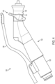
FIG. 8 shows a side view schematic representation of thewire driver 100. Thewire driver 100 comprises a rotating (or indexing) mechanism 166 (FIG. 15 ) allowing for the wire (not shown) to be in a different plane relative to the planar axis of thehandpiece 108. As shown inFIG. 8 , thehandpiece 108 extends along plane z - z. In the first configuration (shown inFIG. 8 ), the grippingportion 110 also extends along plane z - z. - An embodiment of the rotating (indexing)
mechanism 166 is shown inFIG. 15 . The grippingportion 110 rotates about the rotating (indexing)mechanism 166 relative to thehandpiece 108. InFIG. 15 , the rotating (indexing)mechanism 166 also maintains the connection between thegripping portion 110 and thehandpiece 108 as the grippingportion 110 rotates. In the depicted embodiment, the rotating (indexing)mechanism 166 includes aring 168 that extends around both thegripping portion 110 and thehandpiece 108, holding them together. The rotating (indexing)mechanism 166 also includes one or more balls (or spheres) 170 between thering 168 and both thegripping portion 110 andhandpiece 108. Theballs 170 rotate as the grippingportion 110 rotates around thehandpiece 108. Thus, theballs 170 provide allow for movement of thegripping portion 110 about thehandpiece 108, but thering 168 limits the movement such that the grippingportion 110 does not become disconnected from thehandpiece 108. -
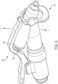
FIG. 9 shows a perspective view schematic representation of thewire driver 100. As shown, the drivingactuator 138 comprises anopening 162 such that the wire (not shown) may extend therethrough. In use, thewire 164 extends through theopening 162 in the drivingactuator 138 and through the grippingportion 110, as shown inFIG. 10 . In the first configuration, as shown inFIGs. 9 and11 , theopening 162 in the drivingactuator 138 is aligned with the grippingportion 110 such that thewire 164 may extend through both theopening 162 and thegripping portion 110. Moreover, in the first configuration, the drivingactuator 138 is in the same plane (along plane z - z) as thehandpiece 108 and thegripping portion 110. -
FIGs. 12-14 show various views schematic representations of thewire driver 100 in a second configuration. In the second configuration, the grippingportion 110 is rotated about the rotating mechanism (not shown) out of plane z - z. In the depicted embodiment, the grippingportion 110 has been rotated 90° relative to plane z - z. However, the grippingportion 110 may be rotatable to any angle relative to the plane z - z. The rotating mechanism (not shown) allows the flexibility of the user (e.g., surgeon) to grip thehandpiece 108 according to his or her personal preference and for greater comfort. Further, if the user selects an overhand grip to hold thewire driver 100, as shown inFIGs. 10 and11 , thewire 164 can be hazardous because it is directly in line with the palm of the user's hand. Assurgical wires 164 typically have pointed tips at both ends, the proximal tip can puncture the surgeon's glove and/or cause injury. Thus, the rotating mechanism (not shown) also serves as a safety feature of thewire driver 100 inFIGs. 8-14 . - All definitions, as defined and used herein, should be understood to control over dictionary definitions, definitions in documents incorporated by reference, and/or ordinary meanings of the defined terms.
- While various embodiments have been described and illustrated herein, those of ordinary skill in the art will readily envision a variety of other means and/or structures for performing the function and/or obtaining the results and/or one or more of the advantages described herein, and each of such variations and/or modifications is deemed to be within the scope of the embodiments described herein. More generally, those skilled in the art will readily appreciate that all parameters, dimensions, materials, and configurations described herein are meant to be exemplary and that the actual parameters, dimensions, materials, and/or configurations will depend upon the specific application or applications for which the teachings is/are used. Those skilled in the art will recognize, or be able to ascertain using no more than routine experimentation, many equivalents to the specific embodiments described herein. It is, therefore, to be understood that the foregoing embodiments are presented by way of example only and that, within the scope of the appended claims and equivalents thereto, embodiments may be practiced otherwise than as specifically described and claimed. Embodiments of the present disclosure are directed to each individual feature, system, article, material, kit, and/or method described herein. In addition, any combination of two or more such features, systems, articles, materials, kits, and/or methods, if such features, systems, articles, materials, kits, and/or methods are not mutually inconsistent, is included within the scope of the present disclosure.
- The terminology used herein is for the purpose of describing particular embodiments only and is not intended to be limiting of the invention. As used herein, the singular forms "a", "an" and "the" are intended to include the plural forms as well, unless the context clearly indicates otherwise. It will be further understood that the terms "comprise" (and any form of comprise, such as "comprises" and "comprising"), "have" (and any form of have, such as, "has" and "having"), "include" (and any form of include, such as "includes" and "including"), and "contain" (any form of contain, such as "contains" and "containing") are open-ended linking verbs. As a result, a method or device that "comprises", "has", "includes" or "contains" one or more steps or elements. Likewise, a step of method or an element of a device that "comprises", "has", "includes" or "contains" one or more features possesses those one or more features, but is not limited to possessing only those one or more features. Furthermore, a device or structure that is configured in a certain way is configured in at least that way, but may also be configured in ways that are not listed.
- The corresponding structures, materials, acts and equivalents of all means or step plus function elements in the claims below, if any, are intended to include any structure, material or act for performing the function in combination with other claimed elements as specifically claimed. The description of the present invention has been presented for purposes of illustration and description, but is not intended to be exhaustive or limited to the invention in the form disclosed. Many modifications and variations will be apparent to those of ordinary skill in the art without departing from the scope and spirit of the invention. The embodiment was chosen and described in order to best explain the principles of one or more aspects of the invention and the practical application, and to enable others of ordinary skill in the art to understand one or more aspects of the present invention for various embodiments with various modifications as are suited to the particular use contemplated.
- According to a first aspect, he present application discloses a wire driver, comprising:
- a housing having a proximal end and a distal end, the housing comprising a handpiece extending from the proximal end to a gripping portion, wherein the gripping portion extends to the distal end;
- a channel extending through the gripping portion;
- a gripping mechanism connected to the channel;
- a first actuator connected to the distal end of the housing and the gripping mechanism; and
- wherein the first actuator is movable between a relaxed position and a compressed position.
- The present application further discloses a wire driver according to the above first aspect, wherein in the relaxed position, the gripping mechanism is closed.
- According to a further aspect, the present application further discloses a wire driver according to the above first aspect, further comprising a drive mechanism positioned within the handpiece and connected to the channel, wherein the drive mechanism is configured to rotate the channel when actuated by a second actuator connected to the handpiece.
- The present application further discloses a wire driver according to the above further aspect, wherein the second actuator extends along the handpiece and at least a portion of the gripping portion.
- According to a third aspect, the present application further discloses a wire driver according to the above first aspect, wherein the gripping portion extends along a first central longitudinal axis. The present application further discloses a wire driver according to the above third aspect, wherein the handpiece is connected to the gripping portion at an angle relative to the first central longitudinal axis.
- The present application further discloses a wire driver according to the above third aspect, wherein the handpiece extends along a second central longitudinal axis, which is parallel to the first central longitudinal axis.
- According to a fourth aspect, the present application further discloses a wire driver according to the above first aspect, further comprising a spring assembly within the gripping portion, the spring assembly connected to the gripping mechanism.
- The present application further discloses a wire driver according to the above fourth aspect, wherein when the first actuator is in the compressed position, the spring assembly is compressed and the gripping mechanism is in an open position.
- The present application further discloses a wire driver according to the above first aspect, wherein the first actuator is movable between a relaxed position and a compressed position, characterized in that the gripping portion is rotatable about the rotating mechanism relative to the handpiece.
Claims (11)
- A wire driver, comprising:a housing having a proximal end and a distal end, the housing comprising a handpiece extending from the proximal end to a gripping portion, wherein the gripping portion extends to the distal end;a channel extending through the gripping portion;a gripping mechanism connected to the channel;a first actuator connected to the distal end of the housing and the gripping mechanism; andwherein the first actuator is movable between a relaxed position and a compressed position,characterized by further comprising a rotating mechanism positioned within the housing, wherein the gripping portion is rotatable about the rotating mechanism relative to the handpiece.
- A powered surgical tool, comprising:a housing having a proximal end and a distal end, the housing comprising a handpiece extending from the proximal end to a gripping portion, wherein the gripping portion extends to the distal end;wherein the gripping portion extends along a central longitudinal axis and the handpiece is connected to the gripping portion at an angle relative to the central longitudinal axis; anda rotating mechanism positioned within the housing, wherein the gripping portion is rotatable about the rotating mechanism relative to the handpiece.
- The surgical tool of claim 2, further comprising a channel extending through the gripping portion and a gripping mechanism connected to the channel.
- The surgical tool of claim 3, further comprising a first actuator connected to the gripping portion and to the gripping mechanism, wherein the first actuator is movable between a relaxed position and a compressed position and in the relaxed position, the gripping mechanism is closed
- The surgical tool of claim 3, further comprising a drive mechanism positioned within the handpiece and connected to the channel, wherein the drive mechanism is configured to rotate the channel when actuated by a second actuator connected to the handpiece.
- The surgical tool of claim 5, wherein the second actuator extends along the handpiece and at least a portion of the gripping portion.
- The surgical tool of claim 5, wherein the second actuator comprises an opening extending therethrough.
- The surgical tool of claim 7, wherein the gripping portion is rotatable between a first position and a second position.
- The surgical tool of claim 8, wherein in the first position, the opening in the second actuator is aligned with the channel in the gripping portion.
- The surgical tool of claim 9, wherein in the second position, the opening in the second actuator is not aligned with the channel in the gripping portion.
- The surgical tool of claim 10, wherein in the first position, the gripping portion and the handpiece extend in the same plane.
Priority Applications (1)
| Application Number | Priority Date | Filing Date | Title |
|---|---|---|---|
| EP25213425.9A EP4666968A3 (en) | 2018-04-09 | 2019-04-08 | Pencil-grip wire driver operated with distally located actuator |
Applications Claiming Priority (3)
| Application Number | Priority Date | Filing Date | Title |
|---|---|---|---|
| US201862654618P | 2018-04-09 | 2018-04-09 | |
| EP19719035.8A EP3773259B1 (en) | 2018-04-09 | 2019-04-08 | Pencil-grip wire driver operated with distally located actuator |
| PCT/US2019/026312 WO2019199666A1 (en) | 2018-04-09 | 2019-04-08 | Pencil-grip wire driver operated with distally located actuator |
Related Parent Applications (2)
| Application Number | Title | Priority Date | Filing Date |
|---|---|---|---|
| EP19719035.8A Division EP3773259B1 (en) | 2018-04-09 | 2019-04-08 | Pencil-grip wire driver operated with distally located actuator |
| EP19719035.8A Division-Into EP3773259B1 (en) | 2018-04-09 | 2019-04-08 | Pencil-grip wire driver operated with distally located actuator |
Related Child Applications (1)
| Application Number | Title | Priority Date | Filing Date |
|---|---|---|---|
| EP25213425.9A Division EP4666968A3 (en) | 2018-04-09 | 2019-04-08 | Pencil-grip wire driver operated with distally located actuator |
Publications (3)
| Publication Number | Publication Date |
|---|---|
| EP4410224A2 true EP4410224A2 (en) | 2024-08-07 |
| EP4410224A3 EP4410224A3 (en) | 2024-09-18 |
| EP4410224B1 EP4410224B1 (en) | 2025-11-05 |
Family
ID=66248767
Family Applications (3)
| Application Number | Title | Priority Date | Filing Date |
|---|---|---|---|
| EP24183855.6A Active EP4410224B1 (en) | 2018-04-09 | 2019-04-08 | Pencil-grip wire driver operated with distally located actuator |
| EP19719035.8A Active EP3773259B1 (en) | 2018-04-09 | 2019-04-08 | Pencil-grip wire driver operated with distally located actuator |
| EP25213425.9A Pending EP4666968A3 (en) | 2018-04-09 | 2019-04-08 | Pencil-grip wire driver operated with distally located actuator |
Family Applications After (2)
| Application Number | Title | Priority Date | Filing Date |
|---|---|---|---|
| EP19719035.8A Active EP3773259B1 (en) | 2018-04-09 | 2019-04-08 | Pencil-grip wire driver operated with distally located actuator |
| EP25213425.9A Pending EP4666968A3 (en) | 2018-04-09 | 2019-04-08 | Pencil-grip wire driver operated with distally located actuator |
Country Status (9)
| Country | Link |
|---|---|
| US (2) | US12029464B2 (en) |
| EP (3) | EP4410224B1 (en) |
| JP (3) | JP7209735B2 (en) |
| KR (4) | KR102734275B1 (en) |
| CN (2) | CN119970145A (en) |
| AU (3) | AU2019251095B2 (en) |
| CA (1) | CA3094246A1 (en) |
| ES (2) | ES2986729T3 (en) |
| WO (1) | WO2019199666A1 (en) |
Families Citing this family (1)
| Publication number | Priority date | Publication date | Assignee | Title |
|---|---|---|---|---|
| WO2025102032A1 (en) | 2023-11-10 | 2025-05-15 | Conmed Corporation | Single device for the activation and control of multiple surgical instruments |
Family Cites Families (51)
| Publication number | Priority date | Publication date | Assignee | Title |
|---|---|---|---|---|
| US592306A (en) * | 1897-10-26 | Mtlo g | ||
| US3847154A (en) * | 1972-09-22 | 1974-11-12 | Weck & Co Edward | Surgical drill with detachable hand-piece |
| US4050528A (en) * | 1975-09-05 | 1977-09-27 | Concept, Inc. | Wire inserter |
| US4298074A (en) * | 1976-08-09 | 1981-11-03 | American Safety Equipment Corporation | Surgical device using impulse motor |
| WO1993025151A1 (en) | 1992-06-12 | 1993-12-23 | Larry Steven Nichter | Wire driver and method |
| US5387217A (en) * | 1993-02-11 | 1995-02-07 | Sefcik; Frank | Disposable bone wire driver |
| US5700275A (en) * | 1996-04-25 | 1997-12-23 | United States Surgical Corporation | Articulating endoscopic surgical instrument |
| US5993466A (en) * | 1997-06-17 | 1999-11-30 | Yoon; Inbae | Suturing instrument with multiple rotatably mounted spreadable needle holders |
| US5902306A (en) | 1997-05-01 | 1999-05-11 | Linvatec Corporation | Surgical wire driver with one-handed gripping attachment |
| US6050989A (en) | 1998-08-24 | 2000-04-18 | Linvatec Corporation | Angularly adjustable powered surgical handpiece |
| KR100341540B1 (en) | 1999-08-19 | 2002-06-22 | 이희영 | Bone-cutting saw using oral cavity |
| US6398551B1 (en) | 1999-09-27 | 2002-06-04 | W & H Dentalwerk Bürmoos GmbH | Angle piece for dental or surgical use |
| US6334743B1 (en) * | 2000-02-09 | 2002-01-01 | Liao Yung-Chuan | High-speed rotary machine |
| FR2840800B1 (en) | 2002-06-12 | 2004-08-27 | Micro Mega Int Mfg Sa | IMPROVEMENT IN TRAINING EQUIPMENT, SAID << CONTRE-ANGLES >>, FOR ROTARY TOOLS USED IN SURGERY, IN PARTICULAR IN DENTAL SURGERY |
| US6786382B1 (en) * | 2003-07-09 | 2004-09-07 | Ethicon Endo-Surgery, Inc. | Surgical stapling instrument incorporating an articulation joint for a firing bar track |
| US20050085798A1 (en) | 2003-09-15 | 2005-04-21 | Hofmann Ronald L. | Adjustable surgical cutting instrument and cam system for use in same |
| US7708756B2 (en) * | 2003-09-29 | 2010-05-04 | Ethicon Endo-Surgery, Inc. | Actuation mechanism for flexible endoscopic device |
| US7785328B2 (en) | 2003-12-30 | 2010-08-31 | Depuy Products, Inc. | Minimally invasive bone miller apparatus |
| CN101258000A (en) * | 2005-04-19 | 2008-09-03 | 布莱克和戴克公司 | Manual Actuator for PTO-Based Clamps |
| US7959050B2 (en) | 2005-07-26 | 2011-06-14 | Ethicon Endo-Surgery, Inc | Electrically self-powered surgical instrument with manual release |
| US8348959B2 (en) | 2006-03-23 | 2013-01-08 | Symmetry Medical Manufacturing, Inc. | Angled surgical driver |
| US8366727B2 (en) * | 2006-06-01 | 2013-02-05 | Ethicon Endo-Surgery, Inc. | Tissue pad ultrasonic surgical instrument |
| US8465491B2 (en) | 2006-06-01 | 2013-06-18 | Osteo Innovations Llc | Bone drill |
| WO2008144552A1 (en) * | 2007-05-17 | 2008-11-27 | Pro-Dex, Inc. | Handheld medical device |
| US8197501B2 (en) * | 2008-03-20 | 2012-06-12 | Medtronic Xomed, Inc. | Control for a powered surgical instrument |
| US9028491B2 (en) * | 2008-08-18 | 2015-05-12 | Alan G. Ellman | MIS electrosurgical handpiece |
| FR2948868B1 (en) | 2009-08-07 | 2011-10-07 | Anthogyr Sa | HAND PIECE WITH ELECTRICAL CONNECTION MEANS |
| DE102010020927A1 (en) * | 2010-05-10 | 2011-11-10 | Karl Storz Gmbh & Co. Kg | Medical instrument with removable handle |
| ITPE20110003A1 (en) | 2011-03-23 | 2012-09-24 | Biomedica Health Srl | SYSTEM OF OPERATION OF A SURGICAL INSTRUMENT AND SURGICAL EQUIPMENT EQUIPPED WITH THIS EQUIPMENT. |
| US8956342B1 (en) * | 2011-09-01 | 2015-02-17 | Microaire Surgical Instruments Llc | Method and device for ergonomically and ambidextrously operable surgical device |
| DE202011052316U1 (en) | 2011-12-15 | 2012-01-19 | Aesculap Ag | Actuating element for medical, preferably surgical instruments with three-finger posture |
| US9456810B2 (en) * | 2012-01-13 | 2016-10-04 | Smith & Nephew, Inc. | Surgical instrument handle assembly |
| US20130253480A1 (en) * | 2012-03-22 | 2013-09-26 | Cory G. Kimball | Surgical instrument usage data management |
| US9375250B2 (en) | 2012-04-09 | 2016-06-28 | Covidien Lp | Method for employing single fault safe redundant signals |
| US10194922B2 (en) | 2012-05-11 | 2019-02-05 | Peter L. Bono | Rotary oscillating bone, cartilage, and disk removal tool assembly |
| EP2702950B1 (en) | 2012-08-30 | 2015-05-20 | Rotomed AG | Medical tool system and handle and tool for a medical tool system |
| US9532783B2 (en) * | 2012-12-17 | 2017-01-03 | Ethicon Endo-Surgery, Llc | Circular stapler with selectable motorized and manual control, including a control ring |
| US10028736B2 (en) * | 2013-03-15 | 2018-07-24 | Novasurg Innovations, Llc | Needle driver |
| US9333019B2 (en) | 2013-03-15 | 2016-05-10 | Arthrex, Inc. | Wire driver |
| US9295522B2 (en) * | 2013-11-08 | 2016-03-29 | Covidien Lp | Medical device adapter with wrist mechanism |
| US20150272596A1 (en) * | 2014-03-27 | 2015-10-01 | MRl lnterventions | Mri compatible surgical motor-powered drivers and related methods |
| US9687257B2 (en) | 2014-06-04 | 2017-06-27 | Zimmer Surgical, Inc. | Pin wire driver device |
| US9363255B2 (en) | 2014-06-04 | 2016-06-07 | Sonos, Inc. | Cloud queue playhead |
| US20160000449A1 (en) * | 2014-07-02 | 2016-01-07 | Peter M. Aman | Sterile ready-to-use surgical tool and attachment system |
| WO2016081604A2 (en) | 2014-11-19 | 2016-05-26 | Stryker Corporation | Surgical wire driver capable of automatically adjusting for the diameter of the wire or pin being driven |
| DE102015111757A1 (en) | 2015-03-09 | 2016-09-15 | Sycotec Gmbh & Co. Kg | Dental or surgical handpiece |
| WO2016167972A1 (en) * | 2015-04-16 | 2016-10-20 | Whitney Surgical Labs, LLC | Surgical tool |
| US10335169B2 (en) | 2015-09-14 | 2019-07-02 | Symmetry Medical Manufacturing, Inc. | Angled orthopaedic driver |
| GB201600546D0 (en) * | 2016-01-12 | 2016-02-24 | Gyrus Medical Ltd | Electrosurgical device |
| US10433856B2 (en) * | 2016-07-11 | 2019-10-08 | Grace Medical, Inc. | Surgical drill handpiece with adjustable cutting tool guard |
| US10499972B2 (en) * | 2017-01-03 | 2019-12-10 | DePuy Synthes Products, Inc. | Mini cable tensioner for orthopedic cable tensioning |
-
2019
- 2019-04-08 WO PCT/US2019/026312 patent/WO2019199666A1/en not_active Ceased
- 2019-04-08 ES ES19719035T patent/ES2986729T3/en active Active
- 2019-04-08 ES ES24183855T patent/ES3060638T3/en active Active
- 2019-04-08 CN CN202510150817.5A patent/CN119970145A/en active Pending
- 2019-04-08 AU AU2019251095A patent/AU2019251095B2/en active Active
- 2019-04-08 KR KR1020237004199A patent/KR102734275B1/en active Active
- 2019-04-08 CN CN201980024479.3A patent/CN111936064B/en active Active
- 2019-04-08 US US17/046,002 patent/US12029464B2/en active Active
- 2019-04-08 KR KR1020227021836A patent/KR102437288B1/en active Active
- 2019-04-08 EP EP24183855.6A patent/EP4410224B1/en active Active
- 2019-04-08 EP EP19719035.8A patent/EP3773259B1/en active Active
- 2019-04-08 CA CA3094246A patent/CA3094246A1/en active Pending
- 2019-04-08 KR KR1020207029684A patent/KR102498764B1/en active Active
- 2019-04-08 EP EP25213425.9A patent/EP4666968A3/en active Pending
- 2019-04-08 JP JP2020555047A patent/JP7209735B2/en active Active
- 2019-04-08 KR KR1020247038307A patent/KR102781655B1/en active Active
-
2021
- 2021-12-22 AU AU2021290275A patent/AU2021290275B2/en active Active
-
2022
- 2022-11-17 JP JP2022184267A patent/JP7463479B2/en active Active
-
2023
- 2023-07-05 AU AU2023204321A patent/AU2023204321B2/en active Active
-
2024
- 2024-03-27 JP JP2024050713A patent/JP7767494B2/en active Active
- 2024-06-17 US US18/744,906 patent/US12514627B2/en active Active
Also Published As
Similar Documents
| Publication | Publication Date | Title |
|---|---|---|
| EP1815809B1 (en) | Handle for surgical instruments | |
| CN101133971B (en) | Articulating curved cutter stapler | |
| JP5312763B2 (en) | Rotating curved cutter stapler | |
| EP2740420A1 (en) | Therapeutic implement | |
| US9585676B1 (en) | Surgical device with variable size wire/pin gripping mechanism | |
| US12514627B2 (en) | Pencil-grip wire driver operated with distally located actuator |
Legal Events
| Date | Code | Title | Description |
|---|---|---|---|
| PUAI | Public reference made under article 153(3) epc to a published international application that has entered the european phase |
Free format text: ORIGINAL CODE: 0009012 |
|
| STAA | Information on the status of an ep patent application or granted ep patent |
Free format text: STATUS: REQUEST FOR EXAMINATION WAS MADE |
|
| 17P | Request for examination filed |
Effective date: 20240621 |
|
| AC | Divisional application: reference to earlier application |
Ref document number: 3773259 Country of ref document: EP Kind code of ref document: P |
|
| AK | Designated contracting states |
Kind code of ref document: A2 Designated state(s): AL AT BE BG CH CY CZ DE DK EE ES FI FR GB GR HR HU IE IS IT LI LT LU LV MC MK MT NL NO PL PT RO RS SE SI SK SM TR |
|
| PUAL | Search report despatched |
Free format text: ORIGINAL CODE: 0009013 |
|
| AK | Designated contracting states |
Kind code of ref document: A3 Designated state(s): AL AT BE BG CH CY CZ DE DK EE ES FI FR GB GR HR HU IE IS IT LI LT LU LV MC MK MT NL NO PL PT RO RS SE SI SK SM TR |
|
| RIC1 | Information provided on ipc code assigned before grant |
Ipc: A61B 17/29 20060101ALN20240812BHEP Ipc: A61B 17/00 20060101ALN20240812BHEP Ipc: A61B 17/16 20060101AFI20240812BHEP |
|
| GRAP | Despatch of communication of intention to grant a patent |
Free format text: ORIGINAL CODE: EPIDOSNIGR1 |
|
| STAA | Information on the status of an ep patent application or granted ep patent |
Free format text: STATUS: GRANT OF PATENT IS INTENDED |
|
| RIC1 | Information provided on ipc code assigned before grant |
Ipc: A61B 17/16 20060101AFI20250717BHEP Ipc: A61B 17/32 20060101ALI20250717BHEP Ipc: A61B 17/00 20060101ALN20250717BHEP Ipc: A61B 17/29 20060101ALN20250717BHEP |
|
| INTG | Intention to grant announced |
Effective date: 20250729 |
|
| GRAS | Grant fee paid |
Free format text: ORIGINAL CODE: EPIDOSNIGR3 |
|
| GRAA | (expected) grant |
Free format text: ORIGINAL CODE: 0009210 |
|
| STAA | Information on the status of an ep patent application or granted ep patent |
Free format text: STATUS: THE PATENT HAS BEEN GRANTED |
|
| AC | Divisional application: reference to earlier application |
Ref document number: 3773259 Country of ref document: EP Kind code of ref document: P |
|
| AK | Designated contracting states |
Kind code of ref document: B1 Designated state(s): AL AT BE BG CH CY CZ DE DK EE ES FI FR GB GR HR HU IE IS IT LI LT LU LV MC MK MT NL NO PL PT RO RS SE SI SK SM TR |
|
| P01 | Opt-out of the competence of the unified patent court (upc) registered |
Free format text: CASE NUMBER: UPC_APP_8658_4410224/2025 Effective date: 20251001 |
|
| REG | Reference to a national code |
Ref country code: CH Ref legal event code: F10 Free format text: ST27 STATUS EVENT CODE: U-0-0-F10-F00 (AS PROVIDED BY THE NATIONAL OFFICE) Effective date: 20251105 Ref country code: GB Ref legal event code: FG4D |
|
| REG | Reference to a national code |
Ref country code: DE Ref legal event code: R096 Ref document number: 602019077966 Country of ref document: DE |
|
| REG | Reference to a national code |
Ref country code: IE Ref legal event code: FG4D |
|
| REG | Reference to a national code |
Ref country code: NL Ref legal event code: MP Effective date: 20251105 |
|
| REG | Reference to a national code |
Ref country code: ES Ref legal event code: FG2A Ref document number: 3060638 Country of ref document: ES Kind code of ref document: T3 Effective date: 20260327 |
|
| PGFP | Annual fee paid to national office [announced via postgrant information from national office to epo] |
Ref country code: GB Payment date: 20260325 Year of fee payment: 8 |
|
| REG | Reference to a national code |
Ref country code: LT Ref legal event code: MG9D |
|
| PG25 | Lapsed in a contracting state [announced via postgrant information from national office to epo] |
Ref country code: NO Free format text: LAPSE BECAUSE OF FAILURE TO SUBMIT A TRANSLATION OF THE DESCRIPTION OR TO PAY THE FEE WITHIN THE PRESCRIBED TIME-LIMIT Effective date: 20260205 |
|
| PG25 | Lapsed in a contracting state [announced via postgrant information from national office to epo] |
Ref country code: HR Free format text: LAPSE BECAUSE OF FAILURE TO SUBMIT A TRANSLATION OF THE DESCRIPTION OR TO PAY THE FEE WITHIN THE PRESCRIBED TIME-LIMIT Effective date: 20251105 Ref country code: FI Free format text: LAPSE BECAUSE OF FAILURE TO SUBMIT A TRANSLATION OF THE DESCRIPTION OR TO PAY THE FEE WITHIN THE PRESCRIBED TIME-LIMIT Effective date: 20251105 Ref country code: AT Free format text: LAPSE BECAUSE OF FAILURE TO SUBMIT A TRANSLATION OF THE DESCRIPTION OR TO PAY THE FEE WITHIN THE PRESCRIBED TIME-LIMIT Effective date: 20251105 |
|
| REG | Reference to a national code |
Ref country code: AT Ref legal event code: MK05 Ref document number: 1853446 Country of ref document: AT Kind code of ref document: T Effective date: 20251105 |
|
| PG25 | Lapsed in a contracting state [announced via postgrant information from national office to epo] |
Ref country code: NL Free format text: LAPSE BECAUSE OF FAILURE TO SUBMIT A TRANSLATION OF THE DESCRIPTION OR TO PAY THE FEE WITHIN THE PRESCRIBED TIME-LIMIT Effective date: 20251105 |
|
| PG25 | Lapsed in a contracting state [announced via postgrant information from national office to epo] |
Ref country code: RS Free format text: LAPSE BECAUSE OF FAILURE TO SUBMIT A TRANSLATION OF THE DESCRIPTION OR TO PAY THE FEE WITHIN THE PRESCRIBED TIME-LIMIT Effective date: 20260205 |
|
| PG25 | Lapsed in a contracting state [announced via postgrant information from national office to epo] |
Ref country code: IS Free format text: LAPSE BECAUSE OF FAILURE TO SUBMIT A TRANSLATION OF THE DESCRIPTION OR TO PAY THE FEE WITHIN THE PRESCRIBED TIME-LIMIT Effective date: 20260305 |
|
| PGFP | Annual fee paid to national office [announced via postgrant information from national office to epo] |
Ref country code: FR Payment date: 20260323 Year of fee payment: 8 |
|
| PG25 | Lapsed in a contracting state [announced via postgrant information from national office to epo] |
Ref country code: PT Free format text: LAPSE BECAUSE OF FAILURE TO SUBMIT A TRANSLATION OF THE DESCRIPTION OR TO PAY THE FEE WITHIN THE PRESCRIBED TIME-LIMIT Effective date: 20260305 |
|
| PG25 | Lapsed in a contracting state [announced via postgrant information from national office to epo] |
Ref country code: PL Free format text: LAPSE BECAUSE OF FAILURE TO SUBMIT A TRANSLATION OF THE DESCRIPTION OR TO PAY THE FEE WITHIN THE PRESCRIBED TIME-LIMIT Effective date: 20251105 |
|
| PG25 | Lapsed in a contracting state [announced via postgrant information from national office to epo] |
Ref country code: LV Free format text: LAPSE BECAUSE OF FAILURE TO SUBMIT A TRANSLATION OF THE DESCRIPTION OR TO PAY THE FEE WITHIN THE PRESCRIBED TIME-LIMIT Effective date: 20251105 |
|
| PG25 | Lapsed in a contracting state [announced via postgrant information from national office to epo] |
Ref country code: BG Free format text: LAPSE BECAUSE OF FAILURE TO SUBMIT A TRANSLATION OF THE DESCRIPTION OR TO PAY THE FEE WITHIN THE PRESCRIBED TIME-LIMIT Effective date: 20251105 |