EP4410213A1 - Method and device for generating a vessel imaging sequence - Google Patents
Method and device for generating a vessel imaging sequence Download PDFInfo
- Publication number
- EP4410213A1 EP4410213A1 EP23155127.6A EP23155127A EP4410213A1 EP 4410213 A1 EP4410213 A1 EP 4410213A1 EP 23155127 A EP23155127 A EP 23155127A EP 4410213 A1 EP4410213 A1 EP 4410213A1
- Authority
- EP
- European Patent Office
- Prior art keywords
- vessel
- input
- imaging sequence
- latent space
- ecg
- Prior art date
- Legal status (The legal status is an assumption and is not a legal conclusion. Google has not performed a legal analysis and makes no representation as to the accuracy of the status listed.)
- Granted
Links
Images




Classifications
-
- G—PHYSICS
- G06—COMPUTING OR CALCULATING; COUNTING
- G06N—COMPUTING ARRANGEMENTS BASED ON SPECIFIC COMPUTATIONAL MODELS
- G06N3/00—Computing arrangements based on biological models
- G06N3/02—Neural networks
- G06N3/04—Architecture, e.g. interconnection topology
- G06N3/045—Combinations of networks
- G06N3/0455—Auto-encoder networks; Encoder-decoder networks
-
- A—HUMAN NECESSITIES
- A61—MEDICAL OR VETERINARY SCIENCE; HYGIENE
- A61B—DIAGNOSIS; SURGERY; IDENTIFICATION
- A61B6/00—Apparatus or devices for radiation diagnosis; Apparatus or devices for radiation diagnosis combined with radiation therapy equipment
- A61B6/48—Diagnostic techniques
- A61B6/481—Diagnostic techniques involving the use of contrast agents
-
- A—HUMAN NECESSITIES
- A61—MEDICAL OR VETERINARY SCIENCE; HYGIENE
- A61B—DIAGNOSIS; SURGERY; IDENTIFICATION
- A61B5/00—Measuring for diagnostic purposes; Identification of persons
- A61B5/0059—Measuring for diagnostic purposes; Identification of persons using light, e.g. diagnosis by transillumination, diascopy, fluorescence
- A61B5/0071—Measuring for diagnostic purposes; Identification of persons using light, e.g. diagnosis by transillumination, diascopy, fluorescence by measuring fluorescence emission
-
- A—HUMAN NECESSITIES
- A61—MEDICAL OR VETERINARY SCIENCE; HYGIENE
- A61B—DIAGNOSIS; SURGERY; IDENTIFICATION
- A61B5/00—Measuring for diagnostic purposes; Identification of persons
- A61B5/02—Detecting, measuring or recording for evaluating the cardiovascular system, e.g. pulse, heart rate, blood pressure or blood flow
- A61B5/02007—Evaluating blood vessel condition, e.g. elasticity, compliance
-
- A—HUMAN NECESSITIES
- A61—MEDICAL OR VETERINARY SCIENCE; HYGIENE
- A61B—DIAGNOSIS; SURGERY; IDENTIFICATION
- A61B5/00—Measuring for diagnostic purposes; Identification of persons
- A61B5/02—Detecting, measuring or recording for evaluating the cardiovascular system, e.g. pulse, heart rate, blood pressure or blood flow
- A61B5/024—Measuring pulse rate or heart rate
- A61B5/0245—Measuring pulse rate or heart rate by using sensing means generating electric signals, i.e. ECG signals
-
- A—HUMAN NECESSITIES
- A61—MEDICAL OR VETERINARY SCIENCE; HYGIENE
- A61B—DIAGNOSIS; SURGERY; IDENTIFICATION
- A61B5/00—Measuring for diagnostic purposes; Identification of persons
- A61B5/24—Detecting, measuring or recording bioelectric or biomagnetic signals of the body or parts thereof
- A61B5/316—Modalities, i.e. specific diagnostic methods
- A61B5/318—Heart-related electrical modalities, e.g. electrocardiography [ECG]
-
- A—HUMAN NECESSITIES
- A61—MEDICAL OR VETERINARY SCIENCE; HYGIENE
- A61B—DIAGNOSIS; SURGERY; IDENTIFICATION
- A61B6/00—Apparatus or devices for radiation diagnosis; Apparatus or devices for radiation diagnosis combined with radiation therapy equipment
- A61B6/02—Arrangements for diagnosis sequentially in different planes; Stereoscopic radiation diagnosis
- A61B6/03—Computed tomography [CT]
- A61B6/032—Transmission computed tomography [CT]
-
- A—HUMAN NECESSITIES
- A61—MEDICAL OR VETERINARY SCIENCE; HYGIENE
- A61B—DIAGNOSIS; SURGERY; IDENTIFICATION
- A61B6/00—Apparatus or devices for radiation diagnosis; Apparatus or devices for radiation diagnosis combined with radiation therapy equipment
- A61B6/48—Diagnostic techniques
- A61B6/486—Diagnostic techniques involving generating temporal series of image data
- A61B6/487—Diagnostic techniques involving generating temporal series of image data involving fluoroscopy
-
- A—HUMAN NECESSITIES
- A61—MEDICAL OR VETERINARY SCIENCE; HYGIENE
- A61B—DIAGNOSIS; SURGERY; IDENTIFICATION
- A61B6/00—Apparatus or devices for radiation diagnosis; Apparatus or devices for radiation diagnosis combined with radiation therapy equipment
- A61B6/50—Apparatus or devices for radiation diagnosis; Apparatus or devices for radiation diagnosis combined with radiation therapy equipment specially adapted for specific body parts; specially adapted for specific clinical applications
- A61B6/504—Apparatus or devices for radiation diagnosis; Apparatus or devices for radiation diagnosis combined with radiation therapy equipment specially adapted for specific body parts; specially adapted for specific clinical applications for diagnosis of blood vessels, e.g. by angiography
-
- A—HUMAN NECESSITIES
- A61—MEDICAL OR VETERINARY SCIENCE; HYGIENE
- A61B—DIAGNOSIS; SURGERY; IDENTIFICATION
- A61B6/00—Apparatus or devices for radiation diagnosis; Apparatus or devices for radiation diagnosis combined with radiation therapy equipment
- A61B6/52—Devices using data or image processing specially adapted for radiation diagnosis
- A61B6/5211—Devices using data or image processing specially adapted for radiation diagnosis involving processing of medical diagnostic data
- A61B6/5217—Devices using data or image processing specially adapted for radiation diagnosis involving processing of medical diagnostic data extracting a diagnostic or physiological parameter from medical diagnostic data
-
- A—HUMAN NECESSITIES
- A61—MEDICAL OR VETERINARY SCIENCE; HYGIENE
- A61B—DIAGNOSIS; SURGERY; IDENTIFICATION
- A61B6/00—Apparatus or devices for radiation diagnosis; Apparatus or devices for radiation diagnosis combined with radiation therapy equipment
- A61B6/52—Devices using data or image processing specially adapted for radiation diagnosis
- A61B6/5211—Devices using data or image processing specially adapted for radiation diagnosis involving processing of medical diagnostic data
- A61B6/5229—Devices using data or image processing specially adapted for radiation diagnosis involving processing of medical diagnostic data combining image data of a patient, e.g. combining a functional image with an anatomical image
-
- A—HUMAN NECESSITIES
- A61—MEDICAL OR VETERINARY SCIENCE; HYGIENE
- A61B—DIAGNOSIS; SURGERY; IDENTIFICATION
- A61B6/00—Apparatus or devices for radiation diagnosis; Apparatus or devices for radiation diagnosis combined with radiation therapy equipment
- A61B6/52—Devices using data or image processing specially adapted for radiation diagnosis
- A61B6/5258—Devices using data or image processing specially adapted for radiation diagnosis involving detection or reduction of artifacts or noise
- A61B6/5264—Devices using data or image processing specially adapted for radiation diagnosis involving detection or reduction of artifacts or noise due to motion
-
- A—HUMAN NECESSITIES
- A61—MEDICAL OR VETERINARY SCIENCE; HYGIENE
- A61B—DIAGNOSIS; SURGERY; IDENTIFICATION
- A61B6/00—Apparatus or devices for radiation diagnosis; Apparatus or devices for radiation diagnosis combined with radiation therapy equipment
- A61B6/52—Devices using data or image processing specially adapted for radiation diagnosis
- A61B6/5288—Devices using data or image processing specially adapted for radiation diagnosis involving retrospective matching to a physiological signal
-
- G—PHYSICS
- G06—COMPUTING OR CALCULATING; COUNTING
- G06F—ELECTRIC DIGITAL DATA PROCESSING
- G06F18/00—Pattern recognition
- G06F18/20—Analysing
- G06F18/21—Design or setup of recognition systems or techniques; Extraction of features in feature space; Blind source separation
- G06F18/213—Feature extraction, e.g. by transforming the feature space; Summarisation; Mappings, e.g. subspace methods
- G06F18/2135—Feature extraction, e.g. by transforming the feature space; Summarisation; Mappings, e.g. subspace methods based on approximation criteria, e.g. principal component analysis
-
- G—PHYSICS
- G06—COMPUTING OR CALCULATING; COUNTING
- G06N—COMPUTING ARRANGEMENTS BASED ON SPECIFIC COMPUTATIONAL MODELS
- G06N3/00—Computing arrangements based on biological models
- G06N3/02—Neural networks
- G06N3/08—Learning methods
-
- G—PHYSICS
- G06—COMPUTING OR CALCULATING; COUNTING
- G06T—IMAGE DATA PROCESSING OR GENERATION, IN GENERAL
- G06T7/00—Image analysis
- G06T7/0002—Inspection of images, e.g. flaw detection
- G06T7/0012—Biomedical image inspection
-
- G—PHYSICS
- G06—COMPUTING OR CALCULATING; COUNTING
- G06T—IMAGE DATA PROCESSING OR GENERATION, IN GENERAL
- G06T7/00—Image analysis
- G06T7/0002—Inspection of images, e.g. flaw detection
- G06T7/0012—Biomedical image inspection
- G06T7/0014—Biomedical image inspection using an image reference approach
- G06T7/0016—Biomedical image inspection using an image reference approach involving temporal comparison
-
- G—PHYSICS
- G06—COMPUTING OR CALCULATING; COUNTING
- G06V—IMAGE OR VIDEO RECOGNITION OR UNDERSTANDING
- G06V10/00—Arrangements for image or video recognition or understanding
- G06V10/70—Arrangements for image or video recognition or understanding using pattern recognition or machine learning
- G06V10/77—Processing image or video features in feature spaces; using data integration or data reduction, e.g. principal component analysis [PCA] or independent component analysis [ICA] or self-organising maps [SOM]; Blind source separation
- G06V10/7715—Feature extraction, e.g. by transforming the feature space, e.g. multi-dimensional scaling [MDS]; Mappings, e.g. subspace methods
-
- G—PHYSICS
- G06—COMPUTING OR CALCULATING; COUNTING
- G06V—IMAGE OR VIDEO RECOGNITION OR UNDERSTANDING
- G06V10/00—Arrangements for image or video recognition or understanding
- G06V10/70—Arrangements for image or video recognition or understanding using pattern recognition or machine learning
- G06V10/82—Arrangements for image or video recognition or understanding using pattern recognition or machine learning using neural networks
-
- G—PHYSICS
- G06—COMPUTING OR CALCULATING; COUNTING
- G06F—ELECTRIC DIGITAL DATA PROCESSING
- G06F2218/00—Aspects of pattern recognition specially adapted for signal processing
- G06F2218/08—Feature extraction
-
- G—PHYSICS
- G06—COMPUTING OR CALCULATING; COUNTING
- G06T—IMAGE DATA PROCESSING OR GENERATION, IN GENERAL
- G06T2207/00—Indexing scheme for image analysis or image enhancement
- G06T2207/10—Image acquisition modality
- G06T2207/10016—Video; Image sequence
-
- G—PHYSICS
- G06—COMPUTING OR CALCULATING; COUNTING
- G06T—IMAGE DATA PROCESSING OR GENERATION, IN GENERAL
- G06T2207/00—Indexing scheme for image analysis or image enhancement
- G06T2207/10—Image acquisition modality
- G06T2207/10064—Fluorescence image
-
- G—PHYSICS
- G06—COMPUTING OR CALCULATING; COUNTING
- G06T—IMAGE DATA PROCESSING OR GENERATION, IN GENERAL
- G06T2207/00—Indexing scheme for image analysis or image enhancement
- G06T2207/10—Image acquisition modality
- G06T2207/10116—X-ray image
- G06T2207/10121—Fluoroscopy
-
- G—PHYSICS
- G06—COMPUTING OR CALCULATING; COUNTING
- G06T—IMAGE DATA PROCESSING OR GENERATION, IN GENERAL
- G06T2207/00—Indexing scheme for image analysis or image enhancement
- G06T2207/20—Special algorithmic details
- G06T2207/20084—Artificial neural networks [ANN]
-
- G—PHYSICS
- G06—COMPUTING OR CALCULATING; COUNTING
- G06T—IMAGE DATA PROCESSING OR GENERATION, IN GENERAL
- G06T2207/00—Indexing scheme for image analysis or image enhancement
- G06T2207/30—Subject of image; Context of image processing
- G06T2207/30004—Biomedical image processing
- G06T2207/30101—Blood vessel; Artery; Vein; Vascular
Definitions
- the invention generally relates to imaging of vessels and more precisely to providing vessel imaging frames indicating vessel information with limited or no use of contrast medium.
- Vessel imaging frames are typically recorded using e.g. angiography or fluoroscopy, which expose a patient to radiation.
- angiography or fluoroscopy typically requires recording vessel imaging frames over a number of cardiac cycles. Accordingly, the patient may be exposed to radiation for an extended period of time.
- contrast medium needs to be applied into the vessels of the patient. Since contrast medium needs to be radio-opaque, contrast medium may include iodine or other substances, which may be detrimental to the renal function of the patient. Accordingly, prolonged contrast medium application during recoding of vessel imaging frames may cause health issues for the patient.
- the present invention provides Method for generating a vessel imaging sequence comprising a plurality of vessel imaging frames and a corresponding electrocardiogram (ECG) signal.
- the method comprises obtaining an input vessel imaging sequence comprising a plurality of input vessel imaging frames and a corresponding input ECG signal, encoding, using a first encoder, the input vessel imaging sequence to generate a plurality of vessel latent space vectors, each vessel latent space vector corresponding to an input vessel imaging frame of the input vessel imaging sequence, encoding, using a second encoder, the ECG signal to generate a plurality of ECG latent space vectors, decoding, using a first decoder, the plurality of vessel latent space vectors and the plurality of ECG latent space vectors to generate the vessel imaging sequence; and decoding, using a second decoder, the vessel latent space vector and the ECG latent space vector to generate the ECG signal.
- the present invention provides a vessel imaging sequence generation device, the vessel imaging sequence including a plurality of vessel imaging frames, comprising at least one processor and a storage medium comprising machine-readable instructions.
- the machine-readable instructions cause the at least one processor to obtain an input vessel imaging sequence comprising a plurality of in-put vessel imaging frames and a corresponding input ECG signal, encode, using a first encoder, the input vessel imaging sequence to generate a plurality of vessel latent space vectors, each vessel latent space vector corresponding to an input vessel imaging of the input vessel imaging sequence, encode, using a second encoder, the ECG signal to generate a plurality of ECG latent space vectors, decode, using a first decoder, the plurality of vessel latent space vectors and the plurality of ECG latent space vectors to generate the vessel imaging sequence and decode, using a second decoder, the vessel latent space vector and the ECG latent space vector to generate the ECG signal.
- the invention generally provides a method and device for generating a vessel imaging sequence and a corresponding ECG signal.
- an input vessel imaging sequence such as an input vessel image sequence, a vessel segmentation sequence or a fluoroscopic imaging sequence
- the vessel latent space vectors collectively form a vessel latent space.
- an input ECG signal is encoded to generate ECG latent space vectors, which may for example respectively correspond to one ECG measurement at a given ECG sampling point.
- the ECG latent space vectors collectively form an ECG latent space.
- Both the vessel latent space and the ECG latent space are then combined to form a combined or modified latent space.
- the modified latent space is then decoded twice, i.e. once to generate the vessel imaging sequence and once to generate the ECG signal corresponding to the vessel imaging sequence.
- FIG. 1 illustrates a flow-chart of the method for generating a vessel imaging sequence
- Fig. 2 illustrates example input vessel imaging frames
- Fig. 3 illustrates a system implementing the method for generating the vessel imaging sequence
- Figs. 6A to 9 illustrate a vessel imaging workflow employing the method for generating a vessel imaging sequence
- Figs. 10 and 11 illustrate devices relating to aspects and the implementation of the method for generating a vessel imaging sequence.
- Fig. 1 illustrates a flowchart of a method 100 for generating a vessel imaging sequence and a corresponding ECG signal.
- Optional steps of method 100 are indicated in Fig. 1 as dashed boxes.
- Sub steps of steps of method 100 are indicated as boxes inside the boxes of their corresponding steps.
- the vessel imaging sequence comprises a plurality of vessel imaging frames, which may e.g. be vessel image frames obtained using angiography, vessel segmentation frames, i.e. frames corresponding to an output of a vessel segmentation process performed on the vessel image frames, or fluoroscopic image frames.
- the vessel imaging frames may be frames which indicate the course of vessels, such as arteries, veins or lymphatic vessels, either based on a contrast-medium or based on vessel segmentation performed using vessel imaging frames indicating a presence of contrast medium.
- the vessel imaging frames may also be frames which indicate a position of a catheter, a guidewire of the catheter or both. Based on the indicated position of the catheter, the guidewire or both within such vessel imaging frames, these vessel imaging frames may likewise indicate the course of vessels.
- fluoroscopic image frames may indicate the course of vessels without contrast medium.
- vessel image frames, input vessel segmentation frames and fluoroscopic frames are provided in Fig. 3 by input frames 210O 1 , 210O 2 and 210O 3 , respectively.
- the ECG signal corresponding to the vessel imaging frames provides a signal indicative of the cardiac action potential of the heart, as e.g. measured with a 12-lead ECG. Accordingly, the ECG signal may provide, for each sampling time, twelve values corresponding to twelve measurements of the cardiac action potential of the heart at twelve different angles. It will be understood, however, that other types of ECG may be used and that accordingly the ECG signal may include more or fewer values per sampling time. Accordingly, the ECG signal may e.g. be considered as a plurality of ECG measurement vectors, wherein the number of ECG measurement vectors in the plurality corresponds to the number of sampling times. Each sampling time corresponds to a sampling time of a vessel imaging frame, i.e. a point in time within a cardiac cycle to which the frame corresponds. For example, if a cardiac cycle is sampled 30 times, the vessel imaging sequence includes 30 vessel imaging frames and the ECG signal includes 30 corresponding ECG measurement vectors.
- step 110 method 100 obtains an input vessel imaging sequence comprising a plurality of input vessel imaging frames and a corresponding input ECG signal.
- method 100 may in step 110 record the input vessel imaging sequence and the input ECG signal or may receive, e.g. on a storage medium or wirelessly, the input vessel sequence and the input ECG signal.
- Obtaining in the context of the present disclosure is thus to be construed as both recording and receiving the input vessel imaging sequence and the corresponding input ECG.
- the input vessel imaging sequence comprises a plurality of input vessel imaging frames, which may e.g. be input vessel image frames recorded using angiography, such as processed or unprocessed x-ray detector values, input vessel segmentation frames, i.e. frames corresponding to an output of a vessel segmentation process performed on the vessel image frames, or input fluoroscopic image frames recorded using fluoroscopy.
- input vessel image frames are shown in Fig.2 .
- Examples of input vessel image frames, input vessel segmentation frames and fluoroscopic frames are provided in Fig. 3 by input frames 210I 1 , 210I 2 and 210I 3 , respectively.
- the input vessel imaging sequence may be one of an input vessel image sequence, an input vessel segmentation sequence derived from the input vessel image sequence and a fluoroscopic imaging sequence.
- the input vessel imaging sequence may be obtained during a single cardiac cycle, as will be discussed in more detail with regard to the subsequent steps of method 100.
- the input vessel imaging sequence indicates the course of vessels.
- the input vessel imaging sequence may not fully indicate the course of the vessels. This may be due to the circulation of contrast medium in the vessels during angiography, leading to the vessels being only partially visible in e.g. the input vessel image frames or the corresponding input vessel segmentation frames of the input vessel imaging frames.
- Fig. 2 shows three exemplary input vessel imaging frames, in which a vessel tree is shown. In each of the three exemplary input vessel images, the vessel tree appears differently due to the circulation of the contrast medium in the vessel tree. Further, the number of sampling times of the input vessel imaging sequence, i.e.
- the temporal resolution of the input vessel imaging sequence is lower than the number of sampling times of the vessel imaging sequence, i.e. the temporal resolution of the vessel imaging sequence. That is, the frame rate of the input vessel imaging sequence may be lower than the frame rate of the vessel imaging sequence.
- the frame rate of the input vessel imaging sequence may be in a range of 7 to 15 frames per second while the frame rate of the vessel imaging sequence may be in a range of 15 to 30 frames per second.
- the lower temporal resolution of the input vessel imaging sequence may likewise lead to the input vessel imaging sequence to not fully indicating the course of the vessels, e.g. due to the circulation of contrast medium through certain vessel branches or by showing the movement of the catheter, the guidewire or both in intervals with a size leading to uncertainty regarding the course of the vessel during the intervals.
- the input ECG signal corresponds to the ECG signal discussed above. Accordingly, the input ECG signal may be considered as a plurality of input ECG measurement vectors, wherein the number of input ECG measurement vectors in the plurality corresponds to the number of sampling times. However, like the input vessel imaging sequence compared to the vessel imaging sequence, the temporal resolution, i.e. the number of sampling times, of the input ECG signal is lower than the temporal resolution of the ECG signal. Accordingly, the input ECG signal may not render visible ECG measurement information of some parts of the cardiac cycle.
- An example of an input ECG signal is for example shown in Fig. 3 , which illustrates input ECG signal 2201.
- Step 110 may include a step 111, in which method 100 derives the input ECG signal from the input vessel imaging sequence.
- method 100 may not directly obtain the input ECG signal but may derive the input ECG signal at respective sampling times based on the respective input vessel imaging frames.
- Method 100 may derive the input ECG signal e.g. by analyzing the changes of the course of the vessels or the change of the position of a catheter tip shown in the respective input vessel imaging frames since these changes are at least in part caused by cardiac motion.
- method 100 may in step 111 analyze these changes in order to determine the cardiac motion occurring between input vessel imaging frames and may then, based on the determined cardiac motion, determine the ECG signal at the sampling time of the input vessel imaging frame.
- method 100 derives the vessel imaging sequence from the input vessel imaging sequence by increasing the temporal resolution compared to the input vessel imaging sequence.
- This increase in temporal resolution starting from the input vessel imaging sequence extracts the indication of the course of the vessel not visible in the input vessel imaging frames based on their temporal relationship and renders them visible in the vessel imaging sequence generated by method 100.
- step 120 method 100 encodes, using a first encoder, the input vessel imaging sequence to generate a plurality of vessel latent space vectors.
- Each vessel latent space vector corresponds to an input vessel imaging frame of the input vessel imaging sequence.
- method 100 converts each input vessel imaging frame into a latent space vector, i.e. a vector in a latent space.
- the latent space represents aspects of input vessel imaging frames, which indicate, if present in an input vessel imaging frame, the presence of a vessel indication, such as a vessel, a vessel segment, a catheter or a guidewire at a given position in the respective vessel image frame.
- Each element of a vessel latent space vector thus provides a weight of the vessel indications within an input vessel imaging frame.
- the first encoder is trained with example input vessel imaging frames.
- the first encoder may for example be a convolutional neural network, a principal component analysis or a transformer-based neural network architecture.
- the latent space may be defined by the elements of the last layer of the convolutional neural network or the number of principal components, i.e. orthogonal unit vectors, determined by the principal component analysis, each respectively trained on example input vessel imaging frames.
- the respective vessel latent space vectors may respectively be activations of the elements of the last layer or weightings of the unit vectors.
- step 130 method 100 encodes, using a second encoder, the input ECG signal to generate a plurality of ECG latent space vectors.
- Each ECG latent space vector corresponds to an input ECG measurement vector.
- the ECG measurement vector indicates the measurement of cardiac action potentials measured at various angles
- the ECG latent space vector indicates a weight of features of the ECG measurements indicative of the cardiac cycle, as defined by an ECG latent space. Accordingly, the ECG latent space defines the features of the ECG measurements indicative of the cardiac cycle.
- the second encoder is trained with example input ECG signals in order to identify the features of the ECG measurements indicative of the cardiac cycle.
- the second encoder may thus be a convolutional neural network, a principal component analysis or a transformer-based neural network architecture.
- the latent space may be defined accordingly, leading to ECG latent space vectors defining e.g. activations of the elements of the last layer or weightings of the unit vectors.
- the input vessel imaging frames and the input ECG signal may be used to respectively further train the first encoder and the second encoder.
- step 140 method 100 decodes, using a first decoder, the plurality of vessel latent space vectors and the plurality of ECG latent space vectors to generate the vessel imaging sequence.
- the first decoder receives the plurality of vessel latent space vectors and the plurality of ECG latent space vectors as input and generates the vessel imaging sequence based on this input.
- the vessel latent space vectors provide a weight of the vessel indications within an input vessel imaging frame and the ECG latent space vectors provide a weight of features of the ECG measurements indicative of the cardiac cycle.
- method 100 takes both latent space vectors and generates the vessel imaging sequence based thereon.
- method 100 interpolates between the vessel latent space vectors while using the ECG latent space vectors as guidance of the interpolation.
- the vessel latent space vectors may be used to determine an interpolation weight between vessel latent space vectors or may be used to otherwise inform the interpolation of the vessel latent space vectors.
- the accordingly interpolated vessel latent space vectors are then used by the first decoder to generate the vessel imaging sequence by reconstructing the vessel imaging frames from the interpolated vessel latent space vectors.
- the first decoder may thus be a convolutional neural network, a principal component analysis or a transformer-based neural network architecture, like the first encoder and the second encoder.
- the architecture of the first decoder corresponds to the first encoder.
- step 150 method 100 decodes, using a second decoder, the vessel latent space vector and the ECG latent space vector to generate the ECG signal.
- the second decoder receives the plurality of vessel latent space vectors and the plurality of ECG latent space vectors as input and generates the vessel imaging sequence based on this input.
- step 150 takes both pluralities of latent space vectors and generates the ECG signal based on both pluralities of latent space vectors. While in step 140 the ECG latent space vectors served as guidance for the interpolation of the vessel latent space vectors, in step 150 the vessel latent space vectors serve as guidance for the interpolation of the ECG latent space vectors. Thus, to achieve a higher temporal resolution of the ECG signal compared to the input ECG signal, the second decoder interpolates the ECG latent space vectors based e.g. on an interpolation weight or otherwise informed by the vessel latent space vectors.
- the accordingly interpolated ECG latent space vectors are then used by the second decoder to generate the ECG signal by reconstructing the ECG measurement values at each interpolated sampling time from the interpolated vessel latent space vectors.
- the second decoder may thus be a convolutional neural network, a principal component analysis or a transformer-based neural network architecture, like the previously discussed encoders and decoders.
- the architecture of the second decoder corresponds to the second encoder.
- method 100 provides a vessel imaging sequence having a high temporal resolution while reducing the radiation exposure and the exposure to contrast medium, if applied.
- the plurality of vessel latent space vectors and the plurality of ECG latent space vectors may respectively be configured to enable a reconstruction of the input vessel imaging sequence and of the input ECG signal.
- both the first encoder and the first decoder may be considered as forming a first modified latent space autoencoder due to the plurality of vessel latent space vectors and the plurality of ECG latent space vectors effectively forming a modified latent space due to their combination.
- the second encoder and the second decoder may be considered as forming a second modified latent space autoencoder.
- Method 100 may further include a step 160, in which method 100 may derive at least one of a respiratory motion model and a cardiac motion model from the plurality of vessel latent space vectors and the plurality of ECG latent space vectors.
- the respiratory motion model and a cardiac motion model may be derived based on changes between adjacent vessel latent space vectors and adjacent ECG latent space vectors, respectively. Adjacent in this context refers to being adjacent in time, e.g. corresponding to adjacent sampling times.
- the respiratory motion model and a cardiac motion model can be respectively derived form the plurality of vessel latent space vectors and the plurality of ECG latent space vectors since the changes between adjacent vessel latent space vectors and adjacent plurality of ECG latent space vectors are caused by the breathing motion and the cardiac motion of the vessels.
- the first encoder and the second encoder may also be trained with the vessel imaging sequence following its generation.
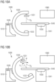
- Figs. 10A and 10B both show a medical imaging system 1000 including a rotatable C arm 1030.
- X-ray emission means 1031 and X-ray detection means 1032 may be mounted on C arm 1030.
- C arm 1030 is in a neutral position P 0 , i.e. X-ray emission means 1031 are located directly above a patient surface 1040.
- Fig. 10B C arm 1030 and thereby X-ray emission means 1031 are rotated counter-clockwise with respect to neutral position P 0 of C-arm 1030 in Fig.
- the neutral position may be used as an imaging position. In such a case, the angiography angle is 0°. Further, in case of a single axis angiography system, the neutral position is typically defined as shown in Fig.10A . In multiple axis angiography systems, additional C arms may be present, such as a ceiling mounted C arm. In such a case, the neutral position may be defined as the position in which X-ray emission means 1031 and X-ray detection means 1032 are at the same level as a patient on patient surface 1040.
- the angiography angle is based on the position of X-ray emission means 1031, the angiography angle may analogously be defined based on the position of X-ray detection means 1032.
- Fig. 3 illustrates a system 200 implementing method 100.
- System 200 may include a first modified latent-space autoencoder 210 and a second modified latent-space autoencoder 220.
- First modified latent space autoencoder 210 includes a first encoder 211 and a first decoder 212.
- First encoder 211 is configured to generate the vessel latent space vectors discussed above based on receiving the input vessel imaging sequence. First encoder 211 may thus implement step 120 of method 100.
- the input vessel imaging sequence is illustrated by exemplary input vessel image frame 210I 1 , exemplary input vessel segmentation frame 210I 2 and exemplary input fluoroscopic frame 210I 3 .
- the vessel latent space vectors are illustrated in Fig.3 by vessel latent space vectors 211L.
- Vessel latent space vectors 211L and ECG latent space vectors 221L are provided to first decoder 212 to generate the vessel imaging sequence, illustrated in Fig.
- First decoder 221 may thus implement step 140 of method 100.
- Vessel latent space vectors 211L and ECG latent space vectors 221L may be considered as a modified latent space 210L, as indicated by the box around vessel latent space vectors 211L and ECG latent space vectors 221L.
- Second modified latent space autoencoder 220 includes a second encoder 221 and a first decoder 222.
- First encoder 221 is configured to generate the ECG latent space vectors discussed above based on receiving the input ECG signal. Second encoder 221 may thus implement step 130 of method 100.
- the input ECG sequence is illustrated by exemplary ECG input signal 220I.
- the ECG latent space vectors are illustrated in Fig.3 by vessel latent space vectors 221L.
- ECG latent space vectors 221L and vessel latent space vectors 211L are provided to second decoder 222 to generate the ECG signal, illustrated in Fig. 3 by exemplary ECG signal 220O.
- Second decoder 222 may thus implement step 150 of method 100.
- ECG latent space vectors 221L and vessel latent space vectors 211L may be considered as a modified latent space 220L, as indicated by the box around ECG latent space vectors 221L and vessel latent space vectors 211
- method 100 and system 200 may be employed in a vessel imaging workflow, which will be discussed in the following.
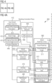
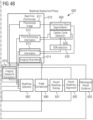
- Figs. 4, 4A and 4B show a schematic diagram of a vessel imaging workflow.
- Fig. 4 shows the orientation of Figs. 4A and 4B with regard to one another.
- the lines shown in Figs. 4A and 4B indicate where various data, such as vessel image 412 or the output of processing entities, such as vessel segmentation 450, is provided to.
- the blocks shown in Fig. 4 indicate both processing entities, such as cardiac cycle detection 420, and stored data elements, such as vessel roadmap 510.
- the workflow is separated into two phases, i.e., a roadmap generation phase 400 and a roadmap deployment phase 600.
- Roadmap generation phase 400 is shown in Fig. 4A .
- Roadmap deployment phase 600 is shown in Fig. 4B .
- a vessel image sequence 410 is processed to generate a vessel roadmap library 600.
- Vessel roadmap library 500 is then deployed in roadmap deployment phase 600 to provide a dynamic vessel roadmap for guidance of a fluoroscopy object during fluoroscopy.
- roadmap generation phase 400 will be described.
- Input vessel image sequence 410 may include a plurality of vessel images 412, which corresponds to the input vessel image frames discussed above.
- vessel images 412 may be stored as or may be Digital Imaging and Communications in Medicine (DICOM) images.
- DICOM Digital Imaging and Communications in Medicine
- Vessel image sequence 410 may include imaging physiological information 411.
- Imaging physiological information 411 may be any physiological information of a patient recorded while the imaging method used to obtain vessel images 412 is performed and which may be used to later overlay and align vessel roadmaps with a real-time fluoroscopy image.
- imaging physiological information 411 may be recorded at approximately the same point in time as the corresponding vessel image 412.
- imaging physiological information 411 may include or may be an electrocardiogram (ECG) recorded while the imaging method used to obtain vessel images 412 is performed.
- ECG electrocardiogram
- imaging physiological information may be stored as or may be a DICOM data tag included in the DICOM image file of the corresponding vessel image 412. Imaging physiological information 411 may be included in, e.g. stored as part of, first alignment data 812 of a vessel roadmap 610.
- Imaging information 413 may indicate one or more parameters associated with an imaging method used to obtain vessel image frames 412. As discussed above, the imaging method used to obtain vessel image frames 412 may for example be angiography. Accordingly, imaging information 413 may include at least one of an angiography angle and a contrast medium dosage.
- the contrast medium dosage may indicate the dosage of radio-opaque contrast medium administered to a patient in order to render the vessels of the patient visible during the imaging method.
- the contrast medium dosage may be measured in milliliters per kilogram of body weight. In the case of contrast media including iodine, the contrast medium dosage may also be measured in milligram iodine per kilogram of body weight.
- Vessel images 412 may be processed by contrast detection 440 to detect contrasted vessel images among the plurality of vessel images 412. Contrast detection 440 may detect contrasted vessel images by detecting the presence of contrast medium in vessel images 412. Contrast detection 440 may in some examples of the present disclosure analyze the pixels of each vessel image frame 412 to detect, based on a property of the pixels, the presence of contrast medium in the respective vessel image 412. The property of the pixels may e.g. a brightness value or a color value. In some embodiments, a vessel image 412 may be identified as a contrasted vessel image if a single pixel indicative of contrast medium is identified.
- a vessel image 412 may be identified as a contrasted vessel image if a number of pixels indicative of contrast medium which exceeds a contrast medium detection threshold is identified.
- contrast detection 440 may detect contrasted vessel images among the plurality of vessel images using a deep learning model, such as DeepNet, which identifies contrast medium in the vessel images 412 and provides a frame-by-frame classification of the input vessel image sequence 410. The contrasted vessel images detected by contrast detection 440 are then provided to vessel segmentation 450 and contrast application segmentation 460.
- DeepNet deep learning model
- each contrasted vessel image may be included in, e.g. stored as part of, a vessel roadmap image 511 of vessel roadmap 510.
- contrast detection 440 may also take into account the contrast medium dosage indicated by imaging parameters 413.
- the contrasted vessel images detected by contrast detection 440 are provided to vessel segmentation 450, vessel imaging sequence generation 460 contrast application segmentation 470 and pathological vessel detection 480. Furthermore, each contrasted vessel image may be included in, e.g., stored as part of, a vessel roadmap image 411 of vessel roadmap 410.
- Vessel segmentation 450 may perform vessel segmentation on the contrasted vessel images to generate vessel segmentation data, i.e. vessel segmentation frames. Accordingly, vessel segmentation 450 may generate data indicative of the position and/or the course of the vessels within the contrasted vessel images. Vessel segmentation data may be generated by vessel generation 450 based on a variety of image segmentation approaches, such as based on convolutional neural networks (CNN), e.g. U-Net, densely connected neural networks, deep-learning methods, graph-partitioning methods, e.g. Markoff random fields (MRF), or region-growing methods, e.g. split- and-merge segmentation.
- CNN convolutional neural networks
- U-Net densely connected neural networks
- deep-learning methods deep-learning methods
- graph-partitioning methods e.g. Markoff random fields (MRF)
- region-growing methods e.g. split- and-merge segmentation.
- split- and-merge segmentation e.g. split- and-mer
- vessel segmentation 450 is shown in Fig. 4A as processing contrasted vessel image frames, vessel segmentation may also directly process vessel images frames 412 to generate vessel segmentation data prior to detecting contrasted vessel images.
- vessel segmentation 450 may also be incorporated into or be part of contrast detection 440. In such embodiments, detecting pixels indicative of contrast mediums may at the same time be used to generate vessel segmentation data.
- Vessel imaging sequence generation 460 may be implemented by method 100 of Fig. 1 and may thus increase the temporal resolution of input vessel image frames 412 by generating vessel roadmap image frames, i.e. vessel roadmap images 511 based on input vessel image frames.
- Contrast application object segmentation 470 may perform contrast application object segmentation on the contrasted vessel images to generate contrast application object segmentation data. Accordingly, contrast application object segmentation data may identify a position and/or the course of the contrast application object in the contrasted vessel images. More precisely, the contrast application object segmentation data may in some embodiments be a catheter, which is used to apply the contrast medium. In other words, contrast application object segmentation 460 may for example detect a tip of a catheter and. The contrast application object segmentation data, i.e. e.g. the valid detected position of the tip of the catheter, may then be included in, e.g. stored as part of, second alignment data 513 of vessel roadmap 510.
- contrast application object segmentation 470 is shown in Fig. 4A as processing contrasted vessel images
- contrast application object segmentation 460 may also directly process vessel images 412, e.g. based on step 111a of method 100.
- Both vessel segmentation 450 and contrast application object segmentation 460 perform image segmentation on vessel images 412 or contrasted vessel images, respectively.
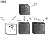
- Fig. 7 shows three example segmentations of a vessel image 712. From left to right, Fig. 7 shows an example of vessel segmentation data 451 and two examples of contrast application object segmentation data 461.
- vessel segmentation data 451 indicate the position and the course of the vessels in vessel image 412.
- the left vessel segmentation data 461 indicate the position and the course of a catheter body 461a.
- the right vessel segmentation data 461 indicate the position of a catheter tip 461b.
- Pathological vessel detection 480 detects pathological vessels in the contrasted vessel images. To this end, pathological vessel detection 480 performs image segmentation on the contrasted vessel images to identify areas within the contrasted vessel images, which include pathological vessel segments. In one example, pathological vessel detection 480 may detect one or more pathological vessels based on any one of the image segmentation approaches trained on vessel images with annotated pathological vessels. The pathological vessels detected by pathological vessel detection 480 may then be included as pathological vessel data 515 in vessel roadmap 610.
- pathological vessel detection 470 may in a further example detect pathological vessels based on their lumina. Accordingly, pathological vessel detection 470 may first determine centerlines of the vessels included in the contrasted vessel images. Then, pathological vessel detection 470 may determine, based on the centerlines, lumina of the vessels included in each vessel roadmap image of the vessel roadmap library. Finally, pathological vessel detection 470 may detect one or more pathological vessels based on the lumina of the vessels included in the contrasted vessel images.
- a pathological vessel in the context of the present application may be any vessel experiencing a pathological condition, such as a stenosis, a lesion, a vasoconstriction or a vasodilation.
- Pathological vessel detection 480 may further determine, e.g., based on the determined lumen of the pathological vessel, the grade of a pathological condition, e.g. a stenosis in a pathological vessel, as e.g., defined by the Society of Cardiovascular Computed Tomography (SCCT). Accordingly, pathological vessel detection 470 may, based on a comparison of the total lumen with the unobstructed lumen, determine the grade of the stenosis. It will be understood that pathological vessel detection 470 may be able to also grade stenoses in vessels other than the coronary arteries based on the grading system applicable to such vessels.
- SCCT Society of Cardiovascular Computed Tomography
- pathological vessel detection 480 may detect more than one pathological vessel. In such cases, pathological vessel detection 480 may further be able to determine in which order the pathological vessels may be treated during a medical intervention. Such a determination may for example be based on a starting position of a medical intervention and the position of the pathological vessel relative to the starting position or may be based on the grading of the severity of the pathological conditions of the pathological vessels discussed above.
- pathological vessel detection 480 may also perform the detection based on input vessel image frames 412 directly or may be integrated with any one of the other processing entities of roadmap generation phase 400 performing image segmentation, i.e., contrast detection 440, vessel segmentation 450 and contrast application object segmentation 470.
- Imaging physiological information 411 may be processed by cardiac cycle detection 420.
- Cardiac cycle detection 420 may identify one or more cardiac cycles within imaging physiological information 411.
- Cardiac cycle detection 120 may identify at least one cardiac cycle within imaging physiological information 411 by detecting a first R peak and a second R peak within imaging physiological information 411.
- the first and the second R peak may indicate the start and the end, respectively, of a cardiac cycle. It should be understood that any other graphical deflection of an ECG may be used to indicate the start and the end of a cardiac cycle. Accordingly, cardiac cycle detection 420 may e.g. detect a first and a second P wave. Cardiac cycle detection 420 may detect cardiac cycles using any suitable analysis of an ECG. For example, cardiac cycle detection 420 may detect cardiac cycles based on performing different types of analyses based transforms, such as short-time Fourier-transform or based on deriving event vectors from the ECG and providing decision rules, which determine cardiac cycles based on the derived event vectors.
- analyses based transforms such as short-time Fourier-transform or based on deriving event vectors from the ECG and providing decision rules, which determine cardiac cycles based on the derived event vectors.
- the one or more cardiac cycles detected by cardiac cycle detection 420 may be included in, e.g. stored as part of, first alignment data 412. In addition, the one or more cardiac cycles detected by cardiac cycle detection 420 may be provided to EDR detection 430.
- EDR detection 430 may derive, based on the one or more cardiac cycles, an electrocardiogram derived respiratory (EDR) signal.
- EDR electrocardiogram derived respiratory
- the EDR signal may be derived by observing fluctuations between detected different cardiac cycles. Generally speaking, inhaling typically increases and exhaling typically decreases the heart rate. More precisely, such fluctuations can in some embodiments be used to derive the EDR signal by computing for the one or more detected cardiac cycles, the R-to-S peak.
- the R-to-S peak corresponds to the amplitude of the EDR signal.
- the R-to-S-peaks are then interpolated using cubic splines to obtain the EDR signal. It should be understood that in some embodiments, other approaches may be used to obtain an EDR signal from the imaging physiological information 411.
- the EDR signal may be included in, e.g. stored as part of, second alignment data 513.
- EDR detection 430 may be omitted.
- second alignment data 513 may only include contrast application object segmentation data.
- EDR detection 430 may be included in cardiac cycle detection 420.
- the approach used by cardiac cycle detection 420 to identify one or more cardiac cycles may also be able to directly provide an EDR signal or be able to provide an EDR signal based on an intermediate step of the approach.
- Fig. 6 shows an example vessel roadmap 510, including a vessel roadmap image 511, first alignment data 512, second alignment data 513, imaging parameters 514 and pathological vessel information 515.
- Vessel roadmap image 511 may include a vessel image 511a.
- Vessel roadmap image 511a corresponds to a vessel imaging frame generated by method 100, i.e. vessel imaging sequence generation 460, based on vessel input sequence 410.
- vessel roadmap image 511 may include vessel segmentation data 511b generated by vessel segmentation 450. Both vessel roadmap 511a and vessel segmentation data 511b may be used as the roadmap to be laid over a fluoroscopy image during the roadmap deployment phase 600 by vessel overlay roadmap 691 discussed later. Accordingly, vessel roadmap image 511 is the part of vessel roadmap 511 providing the actual vessel roadmap.
- vessel roadmap image 511 may correspond to a vessel image frame as generated by vessel image sequence 460 as well as an image indicating the vessel segmentation data generated by vessel imaging sequence generation 460 based on the vessel segmentation by vessel segmentation 450. In some embodiments, vessel roadmap image 511 may only include an image indicating the vessel segmentation data generated by vessel imaging sequence generation 460 based on the vessel segmentation by vessel segmentation 450, as illustrated by vessel segmentation data 511b in Fig. 6 . In some embodiments, vessel roadmap image 511 may be data indicating the position of vessel pixels, which may subsequently be used to highlight corresponding pixels in a fluoroscopy image as vessel pixels.
- First alignment data 512 may include imaging physiological information 411 as recorded as part of input vessel image sequence 410. Since imaging physiological information 411 may in some embodiments be an ECG, imaging physiological information 411 is shown in Fig. 6 as an alignment ECG 512a. Further, first alignment data 512 may include one or more cardiac cycles as detected by cardiac cycle detection 420. In Fig. 6 , a cardiac cycle 512b is illustrated as indicted by adjacent R peaks in alignment ECG 512a. While first alignment data 512 of vessel roadmap 510 is shown here as based on an ECG curve, it should be understood that alignment ECG 512a and cardiac cycle 512b may typically be stored within second alignment data 512 as an indication of the ECG value, i.e., e.g.
- first alignment data 512 may in some embodiments not include the entire alignment ECG 512a. Instead, first alignment data 512 may e.g., be a tuple with the first value indicating the amplitude and the second value indicating the position within a cardiac cycle. In some embodiments, if more than one cardiac cycle has been identified. Fist alignment data 512 may be a triple with the third value identifying the respective cardiac cycle. In some embodiments, in which cardiac cycle detection 420 is omitted, the cardiac cycle information may be replaced by temporal information indicating an associated point in time of the ECG value relative to other vessel roadmaps 510.
- first alignment data 512 provide data to enable aligning vessel roadmap image 511 with a fluoroscopy image. Vessels shift for a variety of factors, including, but not limited to, cardiac muscle contraction and relaxation, i.e., cardiac motion, as well as breathing. First alignment data 512 enable compensation of vessel shift caused by cardiac motion. To this end, first alignment data 512 provide physiological information relating to the heart. It should therefore be understood that first alignment data 512 generally provide data enabling an alignment of a vessel roadmap with a fluoroscopy image necessitated due to vessel shifts caused by cardiac motion. First alignment data 512 may thus include any cardiac information necessary to compensate such vessel shifts.
- Second alignment data 513 may include an EDR signal 513a generated by EDR detection 430, and contrast application object segmentation data 513b generated by contrast application object segmentation 440.
- EDR signal 513a is shown as a curve in Fig. 6 in order to illustrate EDR signal 513a.
- EDR signal 513a may in some embodiments be a data set indicating the value of EDR signal 513a as well as the temporal position of the value within the EDR signal curve.
- contrast application object segmentation data 513b may in some embodiments be an image indicating the vessel segmentation data.
- contrast application object segmentation data 513b may be data indicating the position of contrast application object pixels.
- second alignment data 513 provide data to enable aligning vessel roadmap image 511 with a fluoroscopy image. While first alignment data 512 are described above as compensating vessel shift caused by cardiac motion, second alignment data 513 may compensate for vessel shift caused by breathing motion. To this end, second alignment data 513 provide both physiological information relating to the breathing and information relating to the position of the contrast application object, which may be shifted due to breathing. It should therefore be understood that second alignment data 513 generally provide data enabling an alignment of a vessel roadmap with a fluoroscopy image necessitated due to vessel shifts caused by breathing motion. Second alignment data 513 may thus include any breathing-related information necessary to compensate such vessel shifts.
- second alignment data 513 may include only one of EDR signal 513a and contrast application object segmentation data 513b since in some embodiments only one of the two may be sufficient to compensate vessel shifts cause by breathing motion.
- EDR signal 513a may be omitted.
- contrast application object segmentation data 513b is generated by contrast application object segmentation 470.
- second alignment data 513 is in some embodiments at least derived from vessel roadmap image 511.
- second alignment data 513 may further be derived from first alignment data 512 in addition to being derived from vessel image 511.
- Imaging parameters 514 may include imaging parameters 413 associated with the imaging method used to obtain input vessel image frame 412 included as the vessel roadmap image 411. As shown in Fig. 6 , imaging parameters 514 may thus include angiography angle 514a and contrast medium dosage 514b.
- Pathological vessel information 515 is generated by pathological vessel detection 470. Accordingly, pathological vessel information 515 indicates pathological vessels in vessel roadmap 512. As illustrated in Fig. 6 , pathological vessel information 515 may e.g. correspond to vessel roadmap 512 with a highlighted region 515S indicating a pathological vessel. In addition to or instead of, pathological vessel information 515 may in some embodiments include data identifying pixels in vessel roadmap 512, which are part of a pathological vessel segment. Generally speaking, pathological vessel information 515 may be any kind of information indicating which of the vessel visible in vessel roadmap 512 is a pathological vessel.
- Vessel roadmap library 500 is the output generated by roadmap generation phase 400. This output may subsequently be deployed during roadmap deployment phase 600.
- roadmap deployment phase 600 may be a medical intervention, such as a percutaneous coronary intervention (PCI).
- PCI percutaneous coronary intervention
- vessel roadmap library 500 can be laid over the real-time fluoroscopy images during the PCI in order to guide a medical specialist through the coronary arteries to e.g., a stenosis without having to use a contrast medium.
- roadmap generation phase 500 may include coronary angiography, which is used to obtain a coronary angiogram. The coronary angiogram in such embodiments corresponds to vessel image sequence 410. Since roadmap deployment phase 600 may be a medical intervention, it may also be referred to as an online phase, while roadmap generation phase 400 may also be referred to as an offline phase.
- Roadmap deployment phase 600 performs real-time fluoroscopy 610 in order to obtain a real-time fluoroscopy image frames 611 and corresponding real-time first fluoroscopy information 612, real-time second fluoroscopy information 613 and imaging parameters 614.
- Real-time fluoroscopy image frame 611 may be an image obtained using real-time fluoroscopy 610. During real-time fluoroscopy 610, no contrast medium needs to be injected into vessel or a vessel tree given that vessel image frames are provided by vessel roadmap library 500. Accordingly, since fluoroscopy is typically performed using X-ray, the only radio-opaque structure visible in the real-time fluoroscopy image frame 611, apart from e.g. bones of the patient, is a fluoroscopy object. Like input vessel image frame 412, real-time fluoroscopy image frame 611 may be stored as a DICOM image.
- First fluoroscopy information 612 may be any kind of fluoroscopy physiological information of a patient on whom real-time fluoroscopy 610 is performed and which may be used to overlay and align vessel roadmaps 511 with fluoroscopy image 511.
- first fluoroscopy information 612 may include an ECG recorded while real-time fluoroscopy 610 is performed.
- first fluoroscopy information 612 may be processed by cardiac cycle detection 620 to identify one or more cardiac cycles based on the ECG. The identified one or more cardiac cycles may then also be included in the real-time fluoroscopy information 612.
- Cardiac cycle detection 620 may detect one or more cardiac cycles in the fluoroscopy ECG in the same manner as cardiac cycle detection 420 may detect one or more cardiac cycles in the ECG recorded while input vessel image sequence 410 is obtained.
- the one or more cardiac cycles identified by cardiac cycle detection 620 may be processed by EDR detection 630.
- EDR detection 630 may derive an EDR signal based on the identified one or more cardiac cycles in the same manner as describe with respect to EDR detection 430.
- the derived EDR signal may then be included in second real-time fluoroscopy information 613.
- EDR detection 430 may be omitted.
- EDR detection 630 may additionally derive an EDR signal based on the one or more cardiac cycles included in first alignment data 512 of a vessel roadmap 510 selected by roadmap selection 680, which will be discussed in more detail below. It should be noted that EDR detection 630 may also be omitted if EDR detection 430 is omitted. In such embodiments, vessel roadmap selection 680 and vessel roadmap alignment 692 may operate without any EDR signals.
- second real-time fluoroscopy information 613 may include fluoroscopy object segmentation data identifying a position of a fluoroscopy object in fluoroscopy image frame 611.
- the fluoroscopy object may be a fluoroscopy catheter, which may e.g., be used during a medical intervention, such as PCI.
- the fluoroscopy catheter may typically not be used to inject contrast medium into a vessel, though it may still be configured for that purpose.
- Imaging parameters 614 may indicate one or more parameters associated with an imaging method used to obtain real-time fluoroscopy image 811. Accordingly, imaging parameters 614 may correspond to imaging parameters 613 and may thus include at least one of a fluoroscopy angle and a contrast medium dosage.
- the data recorded by real-time fluoroscopy 610 and processed by processing entities 620, 630 and 660 is illustrated in Fig. 7 .
- real-time fluoroscopy image frame 611 includes the fluoroscopy image recorded by real time fluoroscopy 610. Typically, only the fluoroscopy object is visible in real-time fluoroscopy image frame 611, unless other radio-opaque structures of the patient are visible.
- First fluoroscopy information 612 includes fluoroscopy ECG 612a recorded during real-time fluoroscopy and one or more cardiac cycles 612b identified by cardiac cycle detection 620.
- first fluoroscopy information 612 may include any cardiac information necessary to compensate vessel shifts when laying one of the vessel roadmap images 511 over real-time fluoroscopy image frame 611. Accordingly, in some embodiments, first fluoroscopy information 612 may only include fluoroscopy ECG 612a or may include other or additional information to compensate vessel shifts when laying one of the vessel roadmap images 511 over real-time fluoroscopy image frame 611.
- fluoroscopy ECG 612a is illustrated as the ECG curve recorded during real-time fluoroscopy 610, in some embodiments only values corresponding to the point on the ECG curve may be included in first real-time fluoroscopy information 612, e.g. a tuple or a triple, respectively, including the amplitude value of the complex lead of the fluoroscopy ECG 612a, the temporal position within the ECG and an indication of the identified cardiac cycle.
- Second real-time fluoroscopy information 613 may include a fluoroscopy EDR signal 613a generated by EDR detection 630 and contrast application object segmentation data 813b generated by contrast application object segmentation 860.
- EDR signal 613a is shown as a curve in Fig. 7 in order to illustrate fluoroscopy EDR signal 613a.
- fluoroscopy EDR signal 613a may in some embodiments be a data set indicating the value of fluoroscopy EDR signal 613a as well as the temporal position of the value within the fluoroscopy EDR signal curve.
- fluoroscopy object segmentation data 613b may in some embodiments be an image indicating the vessel segmentation data.
- fluoroscopy object segmentation data 613b may be data indicating the position of fluoroscopy object pixels.
- Real-time fluoroscopy image frames 611 are processed by fluoroscopy imaging sequence generation 670, which generates a fluoroscopic image sequence based on Real-time fluoroscopy image frames 611 according to method 100 of Fig. 1 .
- the fluoroscopic image sequence generated by fluoroscopy imaging sequence generation 670 and vessel roadmap library 500 may be provided to a vessel roadmap selection 690.
- Vessel roadmap selection 690 may select one of the vessel roadmaps 510 from roadmap library 500 based on comparing first real-time fluoroscopy information 612 with first alignment data 512 of each vessel roadmap 510 in roadmap library 500.
- vessel roadmap selection 680 may compare alignment ECG 512a of each vessel roadmap 510 with fluoroscopy ECG 612a to determine a vessel roadmap 510 approximately corresponding, in terms of the respective alignment ECG 512a, to fluoroscopy ECG 612a.
- a vessel roadmap 510 can be chosen in which the position of the vessels is most similar, due to a similar shift caused by similar cardiac motion, to the position of the vessels in real time fluoroscopy image 611.
- vessel roadmap selection 670 may select a vessel roadmap 510 from roadmap library 500 based on comparing second real-time fluoroscopy information 613 with the second alignment data 513 of each vessel roadmap 510. More precisely, vessel roadmap selection 870 may additionally compare EDR signal 513a of each vessel roadmap 510 with fluoroscopy EDR signal 513a to determine a vessel roadmap 510 approximately corresponding, in terms of the respective EDR signal 513a, to fluoroscopy EDR signal 613a. By selecting a vessel roadmap additionally based on an EDR signal comparison, a vessel roadmap 510 can be chosen in which the position of the vessels is most similar, due to a similar shift caused by similar breathing motion, to the position of the vessels in real time fluoroscopy image 611.
- vessel roadmap selection 670 may, based on an ECG comparison and in some embodiments based on an additional EDR comparison, select a vessel roadmap 510 from vessel roadmap library 500.
- the vessels visible in the accordingly selected vessel roadmap 510 have experienced a similar shift due to cardiac motion as well as due to breathing motion.
- the position of the vessels visible in the accordingly selected vessel roadmap 510 may thus be approximately similar to the position of the vessels in real-time fluoroscopy image 611.
- Angle comparison 690 may compare the angiography angle included in the imaging parameters 514 of vessel roadmap 510 with the fluoroscopy angle included in imaging parameters 614 of real-time fluoroscopy 610.
- the comparison performed by angle comparison 680 may ensure that the view provided by selected vessel roadmap image 511 and the view provided by real-time fluoroscopy image 611 are obtained at approximately the same C-arm position. If the angiography angle and the fluoroscopy angle are approximately the same, the views provided by selected vessel roadmap image 511 and real-time fluoroscopy image 611 are approximately similar.
- angle comparison 690 may decide to refrain from overlaying vessel roadmap image 511 over real-time fluoroscopy image 611. Due the deviation of the views in 3D corresponding to the difference of the angles, vessel roadmap overlay 691 and vessel roadmap alignment 692 may not be able properly overlay and align the views.
- the angle difference threshold may e.g., be 5° or 2°.
- Angle comparison 690 may in some embodiments indicate, via a display, such as display 1060, to a medical specialist operating a medical imaging device, such as medical imaging device 1000, that the angiography angle and the fluoroscopy angle differ. Angle comparison 690 may further indicate how to correct the fluoroscopy angle by indicating the proper angular position to which C arm 1030 of medical imaging device 1200 should be moved. In some embodiments, angle comparison 680 may also be configured to control C arm 1030 and may thus be configured to move C arm 1030 to the proper angular position.
- Vessel roadmap overlay 691 may lay the selected vessel roadmap image 511 of the selected vessel roadmap 510 over the fluoroscopic image sequence generated by fluoroscopy imaging sequence generator 670.
- vessel roadmap overlay 691 may perform the overlay by superimposing vessel image 511a over the fluoroscopic image sequence generated by fluoroscopy imaging sequence generator 670.
- Superimposing vessel image 511a may in some embodiments be achieved by transparent color blending, i.e. two pixel values from vessel image 511a, one corresponding to the pixel value as recorded originally in corresponding vessel image 512 and one corresponding to a color selected for vessel representation, can be simultaneously shown.
- vessel roadmap image 511a may be overlaid with a variable level of opacity.
- vessel segmentation data 511b may be integrated into the fluoroscopic image sequence generated by fluoroscopy imaging sequence generator 670, e.g. by changing the values of the pixels indicated as vessel pixels by vessel segmentation data 511b.
- Fig. 8 provides an example of vessel roadmap overlay 691.
- a frame the fluoroscopic image sequence generated by fluoroscopy imaging sequence generator 670 with a visible fluoroscopy object can be seen prior to the overlay of a vessel roadmap image 511.
- the frame can be seen after the overlay of a vessel roadmap image 511.
- Roadmap image 511 laid over the frame of the fluoroscopic image sequence generated by fluoroscopy imaging sequence generator 670 by vessel roadmap overlay 691 may be aligned by vessel roadmap alignment 692.
- Vessel roadmap alignment 692 aligns overlaid vessel roadmap image 511 and the frame of the fluoroscopic image sequence generated by fluoroscopy imaging sequence generator 670 based on second alignment data 513 and real time second fluoroscopy information 813.
- vessel roadmap alignment 892 aligns the position of the contrast application object with the position of the fluoroscopy object based on contrast application object segmentation data 513b and fluoroscopy object segmentation data 613b.
- vessel roadmap alignment 692 aligns the positions of the contrast application object and the fluoroscopy object, which may both be catheters.
- both object segmentation data 513b and fluoroscopy object segmentation data 613b may each indicate, in some embodiments, a centerline of the respective catheter.
- vessel roadmap alignment 692 aligns vessel roadmap 510 with real-time the frame of the fluoroscopic image sequence generated by fluoroscopy imaging sequence generator 670 by minimizing the sum of squared distances between closest points on the centerlines of the catheters.
- aligning may include in-plane rotation, i.e. rotating the roadmap to achieve better alignment.
- Fig. 9 provides an example of an alignment by vessel roadmap alignment 692 based on catheter centerlines. As can be seen on the left side of Fig. 9 , prior to alignment by vessel roadmap alignment 692, the centerlines are apart from one another. After alignment by vessel roadmap alignment 692, the centerlines are approximately in the same position.
- pathological vessel guidance 693 may provide guidance for the fluoroscopy object to the pathological vessel detected by pathological vessel detection 480 based on the selected vessel roadmap 511 and second fluoroscopy information 613. To this end, pathological vessel guidance 693 may determine a path from the fluoroscopy object to the pathological vessel based on the second real-time fluoroscopy information 613, which includes the fluoroscopy segmentation data, and the vessel segmentation data 511b included in the selected vessel roadmap image 511. In other words, the path may indicate the vessel segments the fluoroscopy object needs to pass through in order to reach the pathological vessel from the current position of the fluoroscopy object within the vessels of a patient. Accordingly, pathological vessel guidance 883 may provide guidance for the fluoroscopy object by indicating the vessel segments through which the fluoroscopy object needs to pass in order to reach the pathological vessel.
- Pathological vessel guidance 693 may in some embodiments. provide the guidance to a medical specialist operating the fluoroscopy object e.g., by displaying the path determined by pathological vessel guidance 693 on a display, such as display 1060, to the medical specialist.
- the fluoroscopy object may be a robot-controlled fluoroscopy object.
- pathological vessel guidance 393 may provide the guidance to the robot-controlled fluoroscopy object to enable the robot-controlled fluoroscopy object to be guided to the pathological vessel.
- vessel roadmap selection 680, vessel roadmap overlay 691 and vessel roadmap alignment 692 select, overlay and align one of the vessel roadmaps 510 with the frame of the fluoroscopic image sequence generated by fluoroscopy imaging sequence generator 670 in order to provide a vessel roadmap during roadmap deployment phase 600.
- a vessel roadmap can be selected, overlaid and aligned with the frame of the fluoroscopic image sequence generated by fluoroscopy imaging sequence generator 670, which corresponds to the actual position of the vessels in the frame of the fluoroscopic image sequence generated by fluoroscopy imaging sequence generator 670 without having to inject contrast medium.
- vessel roadmap selection 680, vessel roadmap overlay 691 and vessel roadmap alignment 692 compensate any motion of the vessels, such as cardiac motion or breathing motion, in order to correctly overlay one of the vessel roadmaps 510 over fluoroscopy image 611. Further, the duration of the fluoroscopy may be reduced based on generated vessel roadmap library 500, thereby reducing radiation exposure due to the guidance provided by pathological vessel guidance 893, which provides direct guidance from the position of the fluoroscopy objection to the pathological vessel. This guidance reduces the durations of medical interventions, such as PCI, since guidance based on the properly selected, overlaid and aligned roadmap may enable fast and reliable navigation with the fluoroscopy object through the vessels.
- Figs. 10A and 10B show an exemplary medical imaging system 1000, which may e.g. be used to obtain the input vessel imaging sequence.
- Medical imaging system 1000 may be used for both angiography and fluoroscopy. However, angiography and fluoroscopy may also be performed on separate systems with largely identical elements.
- medical imaging system 1000 is in neutral position P 0 .
- medical imaging system 1000 is in a rotated position P 1 .
- the angle between the two positions is referred to as the angiography angle or the fluoroscopy angle, depending on the imaging process currently performed by medical imaging system 1000.
- Medical imaging system 1000 includes C arm 1030, on which X-ray emission means 1031 and X-ray detection means 1032 may be mounted.
- C arm 1030 and thereby X-ray emission means 1031 and X-ray detection means 1032 are positioned to center around patient surface 1040.
- X-ray emission means 1031 may emit X-rays which may penetrate through a patient positioned on patient surface 1040.
- X-ray detection means 1032 detects the X -rays emitted from X-ray emission means 1031.
- X-ray emission means 1031 and X-ray detection means 1032 may also collectively be referred to as x-ray imaging means.
- C arm 1030 may be coupled to C arm rotation unit 1020.
- C arm rotation unit 1020 may be any motorized means configured to rotate C arm 1030 according to an angiography angel or a fluoroscopy angle as either instructed by the medical specialist or angle comparison 690.
- C arm rotation unit 1020 may be attached to and controlled by C arm control until 1010.
- C arm control unit 1010 may be any kind of circuitry capable of controlling C arm 1030.
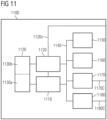
- C arm control unit 1010 may include computing device 1100 of Fig. 11 or may be configured to interface with computing device 1100.
- Medical imaging system 1000 may further include a control panel 1050 mounted onto a side surface of patient surface support 1041.
- Control panel 1050 may be used to control C arm 1030 in embodiments of the present invention in which method 400 displays real-time fluoroscopy image 1011 with an overlaid vessel roadmap image 211 including the path to the one or more pathological vessels to the medical specialist in order to guide the medical specialist to the one or more pathological vessels.
- Fig. 10 does not show any connections between control panel 1050 and C arm 1030 to simplify the depiction of exemplary medical imaging system 1000.
- the connection may be wireless.
- the connection may be wired and may e.g., be integrated into the ceiling of the room where medical imaging system 1000 is located.
- Medical imaging system 1000 may finally also include a display 1060.
- Display 1060 may be used to display information to the medical specialist, such as the vessel imaging sequence generated by method 100 with an overlaid vessel roadmap image 511 including the path to the one or more pathological vessels. Further, display 1060 may be used to display the vessel segmentation data included in overlaid vessel roadmap image 511, including labels for the various vessel segments visible on display 1060.
- display 1060 may be a touch screen, which may be used to toggle the display of the vessel segmentation data on and off.
- display 1060 may further display a confidence level indicating the confidence of roadmap selection 680, vessel comparison 691 and vessel roadmap alignment 692 in the accuracy of the overly and the alignment.
- display 1060 may also display, to the medical specialist, the appropriate angular position of C arm 1030 during fluoroscopy to enable proper overlay and alignment of vessel roadmap image 511 as determined by angle comparison 690.
- Fig. 11 shows a computing device 1100 configured to perform method 100 of Fig. 1 and/or the workflow of Figs. 4A and 4B .
- Computing device 1100 may include a processor 1110, a graphics processing unit (GPU) 1120, a memory 1130, a bus 1140, a storage 1350, a removable storage 1160, an medical imaging system control interface 1170 and a communications interface 1180.
- GPU graphics processing unit
- Processor 1110 may be any kind of single-core or multi-core processing unit employing a reduced instruction set (RISC) or a complex instruction set (CISC).
- RISC reduced instruction set
- CISC complex instruction set
- Exemplary RISC processing units include ARM based cores or RISC V based cores.
- Exemplary CISC processing units include x86 based cores or x86-64 based cores.
- Processor 1310 may further be an application specific integrated circuit (ASIC) or a field-programmable gate-array specially tailored to or programmed, respectively, to perform method 100 and/or the workflow of Figs. 4A and 4B .
- ASIC application specific integrated circuit
- Processor 1110 may perform instructions causing computing device 1100 to perform method 100 and/or the workflow of Figs. 4A and 4B .
- Processor 1110 may be directly coupled to any of the components of computing device 1100 or may be directly coupled to memory 1130, GPU 1320 and bus 1140.
- GPU 1120 may be any kind of processing unit optimized for processing graphics related instructions or more generally for parallel processing of instructions. As such, GPU 1120 may perform part or all of method 100 and/or the workflow of Figs. 4A and 4B to enable fast parallel processing of instructions relating to method 100 and/or the workflow of Figs. 4A and 4B . It should be noted that in some embodiments, processor 1110 may determine that GPU 1120 need not perform instructions relating to method 1100. GPU 1120 may be directly coupled to any of the components of computing device 1100 or may be directly coupled to processor 1110 and memory 1130. GPU 1120 may also be coupled to a display, such as display 1060 of medical imaging system 1000, via connection 1120C. In some embodiments, GPU 1120 may also be coupled to bus 1140.
- Memory 1130 may be any kind of fast storage enabling processor 1110 and GPU 1120 to store instructions for fast retrieval during processing of the instructions well as to cache and buffer data.
- Memory 1130 may be a unified memory coupled to both processor 1110 and GPU 1120 enabling allocation of memory 1130 to processor 1310 and GPU 1320 as needed.
- processor 1310 and GPU 1120 may be coupled to separate processor memory 1130a and GPU memory 1130b.
- Storage 1150 may be a storage device enabling storage of program instructions and other data.
- storage 1150 may be a hard disk drive (HDD), a solid state disk (SSD) or some other type of non-volatile memory.
- Storage 1150 may for example store the instructions of method 100 and/or the workflow of Figs. 4A and 4B as well as the e.g. the input vessel imaging sequence, the vessel imaging sequence and vessel roadmap library 500.
- Removable storage 1160 may be a storage device which can be removably coupled with computing device 1100. Examples include a digital versatile disc (DVD), a compact disc (CD), a Universal Serial Bus (USB) storage device, such as an external SSD, or a magnetic tape. Removable storage 1140 may for example be used to provide the input vessel imaging sequence to computing device 1100 and thereby to method 100 or to store the vessel imaging sequence generated by method 100. It should be noted that removable storage 1160 may also store other data, such as instructions of method 100, or may be omitted.
- DVD digital versatile disc
- CD compact disc
- USB Universal Serial Bus
- Bus 1140 may be any kind of bus system enabling processor 1110 and optionally GPU 1120 to communicate with storage device 1150 and removable storage 960.
- Bus 1140 may for example be a Peripheral Component Interconnect express (PCIe) bus or a Serial AT Attachment (SATA) bus.
- PCIe Peripheral Component Interconnect express
- SATA Serial AT Attachment
- Medical imaging system control interface 1170 may enable computing device 1100 to interface with medical imaging system 1000 via connection 1170C to control C arm 1030 in accordance with the workflow of Figs. 4A and 4B .
- medical imaging system control interface 1170 may be dedicated logic circuitry configured to control rotation of C arm 1030.
- medical imaging system control interface 1170 may be C arm control unit 1110.
- medical imaging system control interface 1170 may also be omitted and computing device 1100 interfaces with medical imaging system 1000 solely via communications interface 1180.
- processor 1110 may control C arm directly via communications interface 1170.
- Medical imaging system control interface 1170 may further be coupled to a robot-controlled fluoroscopy object, e.g. a catheter, in order to guide the robot-controlled fluoroscopy object to the one or more pathological vessels.
- Communications interface 1180 may enable computing device 1100 to interface with external devices, either directly or via network, via connection 1180C.
- Communications interface 1180 may for example enable computing device 1100 to couple to a wired or wireless network, such as Ethernet, Wifi, a Controller Area Network (CAN) bus or any bus system appropriate in medical systems.
- computing device 1100 may be coupled with medical imaging system 1000 via connection 1180C in order to receive the input vessel imaging sequence or to provide, overlay and align a selected vessel roadmap image 511.
- Communications interface may also be a USB port or a serial port to enable direct communication with an external device.
- computing device 1100 may be integrated with medical imaging system 1000.
- computing device 1100 may be integrated with C arm control unit 1030 or may be placed inside patient surface support 1040.
- the invention may further be illustrated by the following examples.
- a method for generating a vessel imaging sequence comprising a plurality of vessel imaging frames and a corresponding electrocardiogram (ECG) signal, comprising obtaining an input vessel imaging sequence comprising a plurality of input vessel imaging frames and a corresponding input ECG signal, encoding, using a first encoder, the input vessel imaging sequence to generate a plurality of vessel latent space vectors, each vessel latent space vector corresponding to an input vessel imaging frame of the input vessel imaging sequence, encoding, using a second encoder, the input ECG signal to generate a plurality of ECG latent space vectors, decoding, using a first decoder, the plurality of vessel latent space vectors and the plurality of ECG latent space vectors to generate the vessel imaging sequence and decoding, using a second decoder, the vessel latent space vector and the ECG latent space vector to generate the ECG signal.
- ECG electrocardiogram
- a frame rate of the input vessel imaging sequence may be lower than a frame rate of the vessel imaging sequence.
- the input vessel imaging sequence may be one of an input vessel image sequence, an input vessel segmentation sequence derived from the input vessel image sequence and an input fluoroscopic imaging sequence.
- the input vessel imaging sequence may be obtained during a single cardiac cycle.
- obtaining the input vessel imaging sequence and the corresponding input ECG signal may include deriving the input ECG signal from the input vessel imaging sequence.
- the method may further comprise deriving at least one of a respiratory motion model and a cardiac motion model from the plurality of vessel latent space vectors and the plurality of ECG latent space vectors.
- the plurality of vessel latent space vectors and the plurality of ECG latent space vectors may respectively be configured to enable a reconstruction of the input vessel imaging sequence and of the input ECG signal.
- the first encoder, the second encoder, the first decoder and the second decoder may be one of a convolutional neural network, a principal component analysis and a transformer-based neural network architecture.
- the first encoder and the first decoder may form a first modified latent space autoencoder and the second encoder and the second decoder may form a second modified latent space autoencoder.
- a vessel imaging sequence generation device the vessel imaging sequence including a plurality of vessel imaging frames, comprises at least one processor; and a storage medium comprising machine-readable instructions, wherein the machine-readable instructions cause the at least one processor to obtain an input vessel imaging sequence comprising a plurality of input vessel imaging frames and a corresponding input ECG signal, encode, using a first encoder, the input vessel imaging sequence to generate a plurality of vessel latent space vectors, each vessel latent space vector corresponding to an input vessel imaging of the input vessel imaging sequence, encode, using a second encoder, the ECG signal to generate a plurality of ECG latent space vectors, decode, using a first decoder, the plurality of vessel latent space vectors and the plurality of ECG latent space vectors to generate the vessel imaging sequence and decode, using a second decoder, the vessel latent space vector and the ECG latent space vector to generate the ECG signal.
- a frame rate of the input vessel imaging sequence may be lower than a frame rate of the vessel imaging sequence.
- the input vessel imaging sequence may be one of an angiographic imaging sequence, a vessel segmentation sequence derived from the angiographic imaging sequence and a fluoroscopic imaging sequence.
- the input vessel imaging sequence may be obtained during a single cardiac cycle.
- the machine-readable instructions may further cause the at least one processor to derive the input ECG signal from the input vessel imaging sequence.
- the machine-readable instructions may further cause the at least one processor to derive at least one of a respiratory motion model and a cardiac motion model from the plurality of vessel latent space vectors and the plurality of ECG latent space vectors.
Landscapes
- Health & Medical Sciences (AREA)
- Engineering & Computer Science (AREA)
- Life Sciences & Earth Sciences (AREA)
- Medical Informatics (AREA)
- Physics & Mathematics (AREA)
- General Health & Medical Sciences (AREA)
- Molecular Biology (AREA)
- Biomedical Technology (AREA)
- Biophysics (AREA)
- Veterinary Medicine (AREA)
- Surgery (AREA)
- Public Health (AREA)
- Pathology (AREA)
- Animal Behavior & Ethology (AREA)
- Heart & Thoracic Surgery (AREA)
- Theoretical Computer Science (AREA)
- Nuclear Medicine, Radiotherapy & Molecular Imaging (AREA)
- Radiology & Medical Imaging (AREA)
- Computer Vision & Pattern Recognition (AREA)
- High Energy & Nuclear Physics (AREA)
- Optics & Photonics (AREA)
- General Physics & Mathematics (AREA)
- Evolutionary Computation (AREA)
- Artificial Intelligence (AREA)
- Cardiology (AREA)
- Vascular Medicine (AREA)
- Physiology (AREA)
- Data Mining & Analysis (AREA)
- Software Systems (AREA)
- Computing Systems (AREA)
- Dentistry (AREA)
- Oral & Maxillofacial Surgery (AREA)
- General Engineering & Computer Science (AREA)
- Quality & Reliability (AREA)
- Mathematical Physics (AREA)
- Computational Linguistics (AREA)
- Multimedia (AREA)
- Databases & Information Systems (AREA)
- Signal Processing (AREA)
- Pulmonology (AREA)
Abstract
Description
- The invention generally relates to imaging of vessels and more precisely to providing vessel imaging frames indicating vessel information with limited or no use of contrast medium.
- Vessel imaging frames are typically recorded using e.g. angiography or fluoroscopy, which expose a patient to radiation. In order for these vessel imaging frames to include sufficient vessel information, such as contrasted vessel trees or a position and trajectory of a catheter and its guidewire, typically requires recording vessel imaging frames over a number of cardiac cycles. Accordingly, the patient may be exposed to radiation for an extended period of time. Further, at least during angiography contrast medium needs to be applied into the vessels of the patient. Since contrast medium needs to be radio-opaque, contrast medium may include iodine or other substances, which may be detrimental to the renal function of the patient. Accordingly, prolonged contrast medium application during recoding of vessel imaging frames may cause health issues for the patient.
- Therefore, it is an objective of the present invention to reduce the recoding time of vessel imaging frames and the use of contrast medium, if applied, while ensuring that the frames include sufficient vessel information.
- To achieve this objective, the present invention provides Method for generating a vessel imaging sequence comprising a plurality of vessel imaging frames and a corresponding electrocardiogram (ECG) signal. The method comprises obtaining an input vessel imaging sequence comprising a plurality of input vessel imaging frames and a corresponding input ECG signal, encoding, using a first encoder, the input vessel imaging sequence to generate a plurality of vessel latent space vectors, each vessel latent space vector corresponding to an input vessel imaging frame of the input vessel imaging sequence, encoding, using a second encoder, the ECG signal to generate a plurality of ECG latent space vectors, decoding, using a first decoder, the plurality of vessel latent space vectors and the plurality of ECG latent space vectors to generate the vessel imaging sequence; and decoding, using a second decoder, the vessel latent space vector and the ECG latent space vector to generate the ECG signal.
- To further achieve this objective, the present invention provides a vessel imaging sequence generation device, the vessel imaging sequence including a plurality of vessel imaging frames, comprising at least one processor and a storage medium comprising machine-readable instructions. The machine-readable instructions cause the at least one processor to obtain an input vessel imaging sequence comprising a plurality of in-put vessel imaging frames and a corresponding input ECG signal, encode, using a first encoder, the input vessel imaging sequence to generate a plurality of vessel latent space vectors, each vessel latent space vector corresponding to an input vessel imaging of the input vessel imaging sequence, encode, using a second encoder, the ECG signal to generate a plurality of ECG latent space vectors, decode, using a first decoder, the plurality of vessel latent space vectors and the plurality of ECG latent space vectors to generate the vessel imaging sequence and decode, using a second decoder, the vessel latent space vector and the ECG latent space vector to generate the ECG signal.
- Examples of the present disclosure will be described with reference to the following appended drawings, in which like reference signs refer to like elements.
-
Fig. 1 provides a flowchart of a method for generating a vessel imaging sequence according to examples of the present disclosure. -
Fig. 2 illustrates example input vessel imaging frames according to examples of the present disclosure. -
Fig. 3 illustrates a system implementing the method ofFig. 1 according to examples of the present disclosure. -
Figs. 4, 4A and4B show a schematic diagram of a vessel imaging workflow, which employs the method ofFig. 1 according to examples of the present disclosure. -
Fig. 5 shows examples of segmentations which may be obtained from a vessel image sequence according to examples of the present disclosure. -
Fig. 6 shows an example of a vessel roadmap according to examples of the present disclosure. -
Fig. 7 shows an example of a real-time fluoroscopy image and information associated therewith according to examples of the present disclosure. -
Fig. 8 shows examples of laying a vessel roadmap over a real-time fluoroscopy according to examples of the present disclosure. -
Fig. 9 shows an example of overlaying a vessel roadmap and a real-time fluoroscopy image according to examples of the present disclosure. -
Figs. 10A and 10B show an exemplary medical imaging system according to examples of the present disclosure. -
Fig. 11 shows an exemplary computing device according to examples of the present disclosure. - It should be understood that the above-identified drawings are in no way meant to limit the scope of the present disclosure. Rather, these drawings are provided to assist in understanding the present disclosure. The person skilled in the art will readily understand that aspects of the present disclosure shown in one drawing may be combined with aspects in another drawing or may be omitted without departing from the scope of the present disclosure.
- The invention generally provides a method and device for generating a vessel imaging sequence and a corresponding ECG signal. To generate the vessel imaging sequence, an input vessel imaging sequence, such as an input vessel image sequence, a vessel segmentation sequence or a fluoroscopic imaging sequence, is encoded to generate vessel latent space vectors for each vessel imaging frame. The vessel latent space vectors collectively form a vessel latent space. Likewise, an input ECG signal is encoded to generate ECG latent space vectors, which may for example respectively correspond to one ECG measurement at a given ECG sampling point. The ECG latent space vectors collectively form an ECG latent space. Both the vessel latent space and the ECG latent space are then combined to form a combined or modified latent space. The modified latent space is then decoded twice, i.e. once to generate the vessel imaging sequence and once to generate the ECG signal corresponding to the vessel imaging sequence.
- This general concept will now be explained with reference to the appended drawings.
Fig. 1 illustrates a flow-chart of the method for generating a vessel imaging sequence, whileFig. 2 illustrates example input vessel imaging frames andFig. 3 illustrates a system implementing the method for generating the vessel imaging sequence. Figs. 6A to9 illustrate a vessel imaging workflow employing the method for generating a vessel imaging sequence. Finally,Figs. 10 and11 illustrate devices relating to aspects and the implementation of the method for generating a vessel imaging sequence. -
Fig. 1 illustrates a flowchart of amethod 100 for generating a vessel imaging sequence and a corresponding ECG signal. Optional steps ofmethod 100 are indicated inFig. 1 as dashed boxes. Sub steps of steps ofmethod 100 are indicated as boxes inside the boxes of their corresponding steps. - The vessel imaging sequence comprises a plurality of vessel imaging frames, which may e.g. be vessel image frames obtained using angiography, vessel segmentation frames, i.e. frames corresponding to an output of a vessel segmentation process performed on the vessel image frames, or fluoroscopic image frames. In other words, the vessel imaging frames may be frames which indicate the course of vessels, such as arteries, veins or lymphatic vessels, either based on a contrast-medium or based on vessel segmentation performed using vessel imaging frames indicating a presence of contrast medium. The vessel imaging frames may also be frames which indicate a position of a catheter, a guidewire of the catheter or both. Based on the indicated position of the catheter, the guidewire or both within such vessel imaging frames, these vessel imaging frames may likewise indicate the course of vessels. In other words, fluoroscopic image frames may indicate the course of vessels without contrast medium. Examples of vessel image frames, input vessel segmentation frames and fluoroscopic frames are provided in
Fig. 3 by input frames 210O1, 210O2 and 210O3, respectively. - The ECG signal corresponding to the vessel imaging frames provides a signal indicative of the cardiac action potential of the heart, as e.g. measured with a 12-lead ECG. Accordingly, the ECG signal may provide, for each sampling time, twelve values corresponding to twelve measurements of the cardiac action potential of the heart at twelve different angles. It will be understood, however, that other types of ECG may be used and that accordingly the ECG signal may include more or fewer values per sampling time. Accordingly, the ECG signal may e.g. be considered as a plurality of ECG measurement vectors, wherein the number of ECG measurement vectors in the plurality corresponds to the number of sampling times. Each sampling time corresponds to a sampling time of a vessel imaging frame, i.e. a point in time within a cardiac cycle to which the frame corresponds. For example, if a cardiac cycle is sampled 30 times, the vessel imaging sequence includes 30 vessel imaging frames and the ECG signal includes 30 corresponding ECG measurement vectors.
- In
step 110,method 100 obtains an input vessel imaging sequence comprising a plurality of input vessel imaging frames and a corresponding input ECG signal. - It will be understood that
method 100 may instep 110 record the input vessel imaging sequence and the input ECG signal or may receive, e.g. on a storage medium or wirelessly, the input vessel sequence and the input ECG signal. Obtaining in the context of the present disclosure is thus to be construed as both recording and receiving the input vessel imaging sequence and the corresponding input ECG. - The input vessel imaging sequence comprises a plurality of input vessel imaging frames, which may e.g. be input vessel image frames recorded using angiography, such as processed or unprocessed x-ray detector values, input vessel segmentation frames, i.e. frames corresponding to an output of a vessel segmentation process performed on the vessel image frames, or input fluoroscopic image frames recorded using fluoroscopy. Examples of vessel image frames are shown in
Fig.2 . Examples of input vessel image frames, input vessel segmentation frames and fluoroscopic frames are provided inFig. 3 by input frames 210I1, 210I2 and 210I3, respectively. Accordingly, the input vessel imaging sequence may be one of an input vessel image sequence, an input vessel segmentation sequence derived from the input vessel image sequence and a fluoroscopic imaging sequence. The input vessel imaging sequence may be obtained during a single cardiac cycle, as will be discussed in more detail with regard to the subsequent steps ofmethod 100. - Like the vessel imaging sequence, the input vessel imaging sequence indicates the course of vessels. However, the input vessel imaging sequence may not fully indicate the course of the vessels. This may be due to the circulation of contrast medium in the vessels during angiography, leading to the vessels being only partially visible in e.g. the input vessel image frames or the corresponding input vessel segmentation frames of the input vessel imaging frames. This is illustrated in
Fig. 2 , which shows three exemplary input vessel imaging frames, in which a vessel tree is shown. In each of the three exemplary input vessel images, the vessel tree appears differently due to the circulation of the contrast medium in the vessel tree. Further, the number of sampling times of the input vessel imaging sequence, i.e. the temporal resolution of the input vessel imaging sequence, is lower than the number of sampling times of the vessel imaging sequence, i.e. the temporal resolution of the vessel imaging sequence. That is, the frame rate of the input vessel imaging sequence may be lower than the frame rate of the vessel imaging sequence. For example, the frame rate of the input vessel imaging sequence may be in a range of 7 to 15 frames per second while the frame rate of the vessel imaging sequence may be in a range of 15 to 30 frames per second. The lower temporal resolution of the input vessel imaging sequence may likewise lead to the input vessel imaging sequence to not fully indicating the course of the vessels, e.g. due to the circulation of contrast medium through certain vessel branches or by showing the movement of the catheter, the guidewire or both in intervals with a size leading to uncertainty regarding the course of the vessel during the intervals. - The input ECG signal corresponds to the ECG signal discussed above. Accordingly, the input ECG signal may be considered as a plurality of input ECG measurement vectors, wherein the number of input ECG measurement vectors in the plurality corresponds to the number of sampling times. However, like the input vessel imaging sequence compared to the vessel imaging sequence, the temporal resolution, i.e. the number of sampling times, of the input ECG signal is lower than the temporal resolution of the ECG signal. Accordingly, the input ECG signal may not render visible ECG measurement information of some parts of the cardiac cycle. An example of an input ECG signal is for example shown in
Fig. 3 , which illustratesinput ECG signal 2201. - Step 110 may include a
step 111, in whichmethod 100 derives the input ECG signal from the input vessel imaging sequence. In other words,method 100 may not directly obtain the input ECG signal but may derive the input ECG signal at respective sampling times based on the respective input vessel imaging frames.Method 100 may derive the input ECG signal e.g. by analyzing the changes of the course of the vessels or the change of the position of a catheter tip shown in the respective input vessel imaging frames since these changes are at least in part caused by cardiac motion. In other words,method 100 may instep 111 analyze these changes in order to determine the cardiac motion occurring between input vessel imaging frames and may then, based on the determined cardiac motion, determine the ECG signal at the sampling time of the input vessel imaging frame. - As will become apparent by the discussion of the subsequent steps of the
method 100,method 100 derives the vessel imaging sequence from the input vessel imaging sequence by increasing the temporal resolution compared to the input vessel imaging sequence. This increase in temporal resolution starting from the input vessel imaging sequence extracts the indication of the course of the vessel not visible in the input vessel imaging frames based on their temporal relationship and renders them visible in the vessel imaging sequence generated bymethod 100. The same applies to the ECG signal and the input ECG signal. - In step 120,
method 100 encodes, using a first encoder, the input vessel imaging sequence to generate a plurality of vessel latent space vectors. Each vessel latent space vector corresponds to an input vessel imaging frame of the input vessel imaging sequence. In other words,method 100 converts each input vessel imaging frame into a latent space vector, i.e. a vector in a latent space. The latent space represents aspects of input vessel imaging frames, which indicate, if present in an input vessel imaging frame, the presence of a vessel indication, such as a vessel, a vessel segment, a catheter or a guidewire at a given position in the respective vessel image frame. Each element of a vessel latent space vector thus provides a weight of the vessel indications within an input vessel imaging frame. To determine the vessel indications and thereby defining the latent space, the first encoder is trained with example input vessel imaging frames. The first encoder may for example be a convolutional neural network, a principal component analysis or a transformer-based neural network architecture. Accordingly, the latent space may be defined by the elements of the last layer of the convolutional neural network or the number of principal components, i.e. orthogonal unit vectors, determined by the principal component analysis, each respectively trained on example input vessel imaging frames. In these cases, the respective vessel latent space vectors may respectively be activations of the elements of the last layer or weightings of the unit vectors. - In
step 130,method 100 encodes, using a second encoder, the input ECG signal to generate a plurality of ECG latent space vectors. Each ECG latent space vector corresponds to an input ECG measurement vector. However, while the ECG measurement vector indicates the measurement of cardiac action potentials measured at various angles, the ECG latent space vector indicates a weight of features of the ECG measurements indicative of the cardiac cycle, as defined by an ECG latent space. Accordingly, the ECG latent space defines the features of the ECG measurements indicative of the cardiac cycle. To determine the ECG latent space, the second encoder is trained with example input ECG signals in order to identify the features of the ECG measurements indicative of the cardiac cycle. Like the first encoder, the second encoder may thus be a convolutional neural network, a principal component analysis or a transformer-based neural network architecture. The latent space may be defined accordingly, leading to ECG latent space vectors defining e.g. activations of the elements of the last layer or weightings of the unit vectors. - In both
step 120 and 130, the input vessel imaging frames and the input ECG signal may be used to respectively further train the first encoder and the second encoder. - In
step 140,method 100 decodes, using a first decoder, the plurality of vessel latent space vectors and the plurality of ECG latent space vectors to generate the vessel imaging sequence. In other words, the first decoder receives the plurality of vessel latent space vectors and the plurality of ECG latent space vectors as input and generates the vessel imaging sequence based on this input. - As discussed above, the vessel latent space vectors provide a weight of the vessel indications within an input vessel imaging frame and the ECG latent space vectors provide a weight of features of the ECG measurements indicative of the cardiac cycle. In
step 140,method 100 takes both latent space vectors and generates the vessel imaging sequence based thereon. To achieve a higher temporal resolution of the vessel imaging sequence compared to the input vessel imaging sequence,method 100, as part ofstep 140, interpolates between the vessel latent space vectors while using the ECG latent space vectors as guidance of the interpolation. For example, the vessel latent space vectors may be used to determine an interpolation weight between vessel latent space vectors or may be used to otherwise inform the interpolation of the vessel latent space vectors. The accordingly interpolated vessel latent space vectors are then used by the first decoder to generate the vessel imaging sequence by reconstructing the vessel imaging frames from the interpolated vessel latent space vectors. The first decoder may thus be a convolutional neural network, a principal component analysis or a transformer-based neural network architecture, like the first encoder and the second encoder. As will be understood, to enable reconstruction of the vessel image frames, the architecture of the first decoder corresponds to the first encoder. - In
step 150,method 100 decodes, using a second decoder, the vessel latent space vector and the ECG latent space vector to generate the ECG signal. In other words, the second decoder receives the plurality of vessel latent space vectors and the plurality of ECG latent space vectors as input and generates the vessel imaging sequence based on this input. - Similar to step 140,
method 100 instep 150 takes both pluralities of latent space vectors and generates the ECG signal based on both pluralities of latent space vectors. While instep 140 the ECG latent space vectors served as guidance for the interpolation of the vessel latent space vectors, instep 150 the vessel latent space vectors serve as guidance for the interpolation of the ECG latent space vectors. Thus, to achieve a higher temporal resolution of the ECG signal compared to the input ECG signal, the second decoder interpolates the ECG latent space vectors based e.g. on an interpolation weight or otherwise informed by the vessel latent space vectors. The accordingly interpolated ECG latent space vectors are then used by the second decoder to generate the ECG signal by reconstructing the ECG measurement values at each interpolated sampling time from the interpolated vessel latent space vectors. The second decoder may thus be a convolutional neural network, a principal component analysis or a transformer-based neural network architecture, like the previously discussed encoders and decoders. As will be understood, to enable reconstruction of the vessel image frames, the architecture of the second decoder corresponds to the second encoder. - By generating both the vessel image sequence and the ECG signal based on the vessel latent space vectors and the ECG latent space vectors, recording the input vessel imaging sequence during only a single cardiac cycle is sufficient since all information can be extrapolated due to the two pluralities of latent space vectors. This is in contrast to other vessel imaging sequence generations, in particular manual vessel imaging sequence generations, which require recording the input vessel imaging sequence for multiple cardiac cycles, leading to an increased radiation exposure and, if contrast medium is used, also to an increased risk for the renal function of the patient. Accordingly, by generating both the vessel image sequence and the ECG signal based on the vessel latent space vectors and the ECG latent space vectors,
method 100 provides a vessel imaging sequence having a high temporal resolution while reducing the radiation exposure and the exposure to contrast medium, if applied. - To enable
step 140 and step 150, the plurality of vessel latent space vectors and the plurality of ECG latent space vectors may respectively be configured to enable a reconstruction of the input vessel imaging sequence and of the input ECG signal. Further, both the first encoder and the first decoder may be considered as forming a first modified latent space autoencoder due to the plurality of vessel latent space vectors and the plurality of ECG latent space vectors effectively forming a modified latent space due to their combination. Likewise, the second encoder and the second decoder may be considered as forming a second modified latent space autoencoder. -
Method 100 may further include astep 160, in whichmethod 100 may derive at least one of a respiratory motion model and a cardiac motion model from the plurality of vessel latent space vectors and the plurality of ECG latent space vectors. The respiratory motion model and a cardiac motion model may be derived based on changes between adjacent vessel latent space vectors and adjacent ECG latent space vectors, respectively. Adjacent in this context refers to being adjacent in time, e.g. corresponding to adjacent sampling times. The respiratory motion model and a cardiac motion model can be respectively derived form the plurality of vessel latent space vectors and the plurality of ECG latent space vectors since the changes between adjacent vessel latent space vectors and adjacent plurality of ECG latent space vectors are caused by the breathing motion and the cardiac motion of the vessels. - To further improve the generation the vessel imaging sequence, the first encoder and the second encoder may also be trained with the vessel imaging sequence following its generation.
- It will be understood that
method 100 may be performed at any angiography angle or fluoroscopy angle and for any number such angles. Briefly referring toFigs. 10A and 10B , both show amedical imaging system 1000 including arotatable C arm 1030. X-ray emission means 1031 and X-ray detection means 1032 may be mounted onC arm 1030. InFig. 10A ,C arm 1030 is in a neutral position P0, i.e. X-ray emission means 1031 are located directly above apatient surface 1040. InFig. 10B ,C arm 1030 and thereby X-ray emission means 1031 are rotated counter-clockwise with respect to neutral position P0 of C-arm 1030 inFig. 10A to a position P1. The angle between position P0 and position P1, as indicated inFig. 10B , is referred to as the angiography angle or the fluoroscopy angle, depending on the medical imaging process. It will be understood that the neutral position may be used as an imaging position. In such a case, the angiography angle is 0°. Further, in case of a single axis angiography system, the neutral position is typically defined as shown inFig.10A . In multiple axis angiography systems, additional C arms may be present, such as a ceiling mounted C arm. In such a case, the neutral position may be defined as the position in which X-ray emission means 1031 and X-ray detection means 1032 are at the same level as a patient onpatient surface 1040. - While the above definition of the angiography angle is based on the position of X-ray emission means 1031, the angiography angle may analogously be defined based on the position of X-ray detection means 1032.
-
Fig. 3 illustrates asystem 200 implementingmethod 100.System 200 may include a first modified latent-space autoencoder 210 and a second modified latent-space autoencoder 220. - First modified
latent space autoencoder 210 includes afirst encoder 211 and afirst decoder 212.First encoder 211 is configured to generate the vessel latent space vectors discussed above based on receiving the input vessel imaging sequence.First encoder 211 may thus implement step 120 ofmethod 100. The input vessel imaging sequence is illustrated by exemplary input vessel image frame 210I1, exemplary input vessel segmentation frame 210I2 and exemplary input fluoroscopic frame 210I3. The vessel latent space vectors are illustrated inFig.3 by vessellatent space vectors 211L. Vessellatent space vectors 211L and ECGlatent space vectors 221L are provided tofirst decoder 212 to generate the vessel imaging sequence, illustrated inFig. 3 by exemplary vessel image frame 210O1, exemplary vessel segmentation frame 210O2 and exemplary fluoroscopic frame 210O3.First decoder 221 may thus implementstep 140 ofmethod 100. Vessellatent space vectors 211L and ECGlatent space vectors 221L may be considered as a modifiedlatent space 210L, as indicated by the box around vessellatent space vectors 211L and ECGlatent space vectors 221L. - Second modified
latent space autoencoder 220 includes asecond encoder 221 and afirst decoder 222.First encoder 221 is configured to generate the ECG latent space vectors discussed above based on receiving the input ECG signal.Second encoder 221 may thus implementstep 130 ofmethod 100. The input ECG sequence is illustrated by exemplary ECG input signal 220I. The ECG latent space vectors are illustrated inFig.3 by vessellatent space vectors 221L. ECGlatent space vectors 221L and vessellatent space vectors 211L are provided tosecond decoder 222 to generate the ECG signal, illustrated inFig. 3 by exemplary ECG signal 220O.Second decoder 222 may thus implementstep 150 ofmethod 100. ECGlatent space vectors 221L and vessellatent space vectors 211L may be considered as a modifiedlatent space 220L, as indicated by the box around ECGlatent space vectors 221L and vessellatent space vectors 211L. - As will be discussed in the following,
method 100 andsystem 200 may be employed in a vessel imaging workflow, which will be discussed in the following. -
Figs. 4, 4A and4B show a schematic diagram of a vessel imaging workflow.Fig. 4 shows the orientation ofFigs. 4A and4B with regard to one another. The lines shown inFigs. 4A and4B indicate where various data, such asvessel image 412 or the output of processing entities, such asvessel segmentation 450, is provided to. The blocks shown inFig. 4 indicate both processing entities, such ascardiac cycle detection 420, and stored data elements, such asvessel roadmap 510. - The workflow is separated into two phases, i.e., a
roadmap generation phase 400 and aroadmap deployment phase 600. -
Roadmap generation phase 400 is shown inFig. 4A .Roadmap deployment phase 600 is shown inFig. 4B . Duringroadmap generation phase 400, avessel image sequence 410 is processed to generate avessel roadmap library 600.Vessel roadmap library 500 is then deployed inroadmap deployment phase 600 to provide a dynamic vessel roadmap for guidance of a fluoroscopy object during fluoroscopy. First,roadmap generation phase 400 will be described. - Input
vessel image sequence 410 may include a plurality ofvessel images 412, which corresponds to the input vessel image frames discussed above. In some examples of the present disclosure,vessel images 412 may be stored as or may be Digital Imaging and Communications in Medicine (DICOM) images. -
Vessel image sequence 410 may include imagingphysiological information 411. Imagingphysiological information 411 may be any physiological information of a patient recorded while the imaging method used to obtainvessel images 412 is performed and which may be used to later overlay and align vessel roadmaps with a real-time fluoroscopy image. In particular, imagingphysiological information 411 may be recorded at approximately the same point in time as the correspondingvessel image 412. In some embodiments, imagingphysiological information 411 may include or may be an electrocardiogram (ECG) recorded while the imaging method used to obtainvessel images 412 is performed. In some embodiments, imaging physiological information may be stored as or may be a DICOM data tag included in the DICOM image file of thecorresponding vessel image 412. Imagingphysiological information 411 may be included in, e.g. stored as part of, first alignment data 812 of a vessel roadmap 610. - Input
vessel image sequence 410 may includeimaging information 413.Imaging information 413 may indicate one or more parameters associated with an imaging method used to obtain vessel image frames 412. As discussed above, the imaging method used to obtain vessel image frames 412 may for example be angiography. Accordingly, imaginginformation 413 may include at least one of an angiography angle and a contrast medium dosage. - The contrast medium dosage may indicate the dosage of radio-opaque contrast medium administered to a patient in order to render the vessels of the patient visible during the imaging method. The contrast medium dosage may be measured in milliliters per kilogram of body weight. In the case of contrast media including iodine, the contrast medium dosage may also be measured in milligram iodine per kilogram of body weight.
-
Vessel images 412 may be processed bycontrast detection 440 to detect contrasted vessel images among the plurality ofvessel images 412.Contrast detection 440 may detect contrasted vessel images by detecting the presence of contrast medium invessel images 412.Contrast detection 440 may in some examples of the present disclosure analyze the pixels of eachvessel image frame 412 to detect, based on a property of the pixels, the presence of contrast medium in therespective vessel image 412. The property of the pixels may e.g. a brightness value or a color value. In some embodiments, avessel image 412 may be identified as a contrasted vessel image if a single pixel indicative of contrast medium is identified. In some embodiments, avessel image 412 may be identified as a contrasted vessel image if a number of pixels indicative of contrast medium which exceeds a contrast medium detection threshold is identified. In some embodiments,contrast detection 440 may detect contrasted vessel images among the plurality of vessel images using a deep learning model, such as DeepNet, which identifies contrast medium in thevessel images 412 and provides a frame-by-frame classification of the inputvessel image sequence 410. The contrasted vessel images detected bycontrast detection 440 are then provided tovessel segmentation 450 andcontrast application segmentation 460. - Furthermore, each contrasted vessel image may be included in, e.g. stored as part of, a
vessel roadmap image 511 ofvessel roadmap 510. - In some examples of the present disclosure,
contrast detection 440 may also take into account the contrast medium dosage indicated byimaging parameters 413. - The contrasted vessel images detected by
contrast detection 440 are provided tovessel segmentation 450, vesselimaging sequence generation 460contrast application segmentation 470 andpathological vessel detection 480. Furthermore, each contrasted vessel image may be included in, e.g., stored as part of, avessel roadmap image 411 ofvessel roadmap 410. -
Vessel segmentation 450 may perform vessel segmentation on the contrasted vessel images to generate vessel segmentation data, i.e. vessel segmentation frames. Accordingly,vessel segmentation 450 may generate data indicative of the position and/or the course of the vessels within the contrasted vessel images. Vessel segmentation data may be generated byvessel generation 450 based on a variety of image segmentation approaches, such as based on convolutional neural networks (CNN), e.g. U-Net, densely connected neural networks, deep-learning methods, graph-partitioning methods, e.g. Markoff random fields (MRF), or region-growing methods, e.g. split- and-merge segmentation. The vessel segmentation data may then be included in, e.g. stored as part of, avessel roadmap image 511 of avessel roadmap 510. - It should be noted that, while
vessel segmentation 450 is shown inFig. 4A as processing contrasted vessel image frames, vessel segmentation may also directly process vessel images frames 412 to generate vessel segmentation data prior to detecting contrasted vessel images. In some embodiments,vessel segmentation 450 may also be incorporated into or be part ofcontrast detection 440. In such embodiments, detecting pixels indicative of contrast mediums may at the same time be used to generate vessel segmentation data. - Vessel
imaging sequence generation 460 may be implemented bymethod 100 ofFig. 1 and may thus increase the temporal resolution of input vessel image frames 412 by generating vessel roadmap image frames, i.e.vessel roadmap images 511 based on input vessel image frames. - Contrast
application object segmentation 470 may perform contrast application object segmentation on the contrasted vessel images to generate contrast application object segmentation data. Accordingly, contrast application object segmentation data may identify a position and/or the course of the contrast application object in the contrasted vessel images. More precisely, the contrast application object segmentation data may in some embodiments be a catheter, which is used to apply the contrast medium. In other words, contrastapplication object segmentation 460 may for example detect a tip of a catheter and. The contrast application object segmentation data, i.e. e.g. the valid detected position of the tip of the catheter, may then be included in, e.g. stored as part of,second alignment data 513 ofvessel roadmap 510. - While contrast
application object segmentation 470 is shown inFig. 4A as processing contrasted vessel images, contrastapplication object segmentation 460 may also directly processvessel images 412, e.g. based on step 111a ofmethod 100. - Both
vessel segmentation 450 and contrastapplication object segmentation 460 perform image segmentation onvessel images 412 or contrasted vessel images, respectively. To better illustrate possible segmentations performed onvessel images 412 or contrasted vessel images, respectively,Fig. 7 shows three example segmentations of a vessel image 712. From left to right,Fig. 7 shows an example ofvessel segmentation data 451 and two examples of contrast applicationobject segmentation data 461. As can be seen,vessel segmentation data 451 indicate the position and the course of the vessels invessel image 412. The leftvessel segmentation data 461 indicate the position and the course of acatheter body 461a. The rightvessel segmentation data 461 indicate the position of acatheter tip 461b. -
Pathological vessel detection 480 detects pathological vessels in the contrasted vessel images. To this end,pathological vessel detection 480 performs image segmentation on the contrasted vessel images to identify areas within the contrasted vessel images, which include pathological vessel segments. In one example,pathological vessel detection 480 may detect one or more pathological vessels based on any one of the image segmentation approaches trained on vessel images with annotated pathological vessels. The pathological vessels detected bypathological vessel detection 480 may then be included aspathological vessel data 515 in vessel roadmap 610. - Pathological conditions in vessels often affect the lumina of the vessel. Accordingly,
pathological vessel detection 470 may in a further example detect pathological vessels based on their lumina. Accordingly,pathological vessel detection 470 may first determine centerlines of the vessels included in the contrasted vessel images. Then,pathological vessel detection 470 may determine, based on the centerlines, lumina of the vessels included in each vessel roadmap image of the vessel roadmap library. Finally,pathological vessel detection 470 may detect one or more pathological vessels based on the lumina of the vessels included in the contrasted vessel images. - A pathological vessel in the context of the present application may be any vessel experiencing a pathological condition, such as a stenosis, a lesion, a vasoconstriction or a vasodilation.
-
Pathological vessel detection 480 may further determine, e.g., based on the determined lumen of the pathological vessel, the grade of a pathological condition, e.g. a stenosis in a pathological vessel, as e.g., defined by the Society of Cardiovascular Computed Tomography (SCCT). Accordingly,pathological vessel detection 470 may, based on a comparison of the total lumen with the unobstructed lumen, determine the grade of the stenosis. It will be understood thatpathological vessel detection 470 may be able to also grade stenoses in vessels other than the coronary arteries based on the grading system applicable to such vessels. - In some cases,
pathological vessel detection 480 may detect more than one pathological vessel. In such cases,pathological vessel detection 480 may further be able to determine in which order the pathological vessels may be treated during a medical intervention. Such a determination may for example be based on a starting position of a medical intervention and the position of the pathological vessel relative to the starting position or may be based on the grading of the severity of the pathological conditions of the pathological vessels discussed above. - It will be understood that
pathological vessel detection 480 may also perform the detection based on input vessel image frames 412 directly or may be integrated with any one of the other processing entities ofroadmap generation phase 400 performing image segmentation, i.e.,contrast detection 440,vessel segmentation 450 and contrastapplication object segmentation 470. - Imaging
physiological information 411 may be processed bycardiac cycle detection 420.Cardiac cycle detection 420 may identify one or more cardiac cycles within imagingphysiological information 411. Cardiac cycle detection 120 may identify at least one cardiac cycle within imagingphysiological information 411 by detecting a first R peak and a second R peak within imagingphysiological information 411. - The first and the second R peak may indicate the start and the end, respectively, of a cardiac cycle. It should be understood that any other graphical deflection of an ECG may be used to indicate the start and the end of a cardiac cycle. Accordingly,
cardiac cycle detection 420 may e.g. detect a first and a second P wave.Cardiac cycle detection 420 may detect cardiac cycles using any suitable analysis of an ECG. For example,cardiac cycle detection 420 may detect cardiac cycles based on performing different types of analyses based transforms, such as short-time Fourier-transform or based on deriving event vectors from the ECG and providing decision rules, which determine cardiac cycles based on the derived event vectors. - The one or more cardiac cycles detected by
cardiac cycle detection 420 may be included in, e.g. stored as part of,first alignment data 412. In addition, the one or more cardiac cycles detected bycardiac cycle detection 420 may be provided toEDR detection 430. -
EDR detection 430 may derive, based on the one or more cardiac cycles, an electrocardiogram derived respiratory (EDR) signal. The EDR signal may be derived by observing fluctuations between detected different cardiac cycles. Generally speaking, inhaling typically increases and exhaling typically decreases the heart rate. More precisely, such fluctuations can in some embodiments be used to derive the EDR signal by computing for the one or more detected cardiac cycles, the R-to-S peak. The R-to-S peak corresponds to the amplitude of the EDR signal. The R-to-S-peaks are then interpolated using cubic splines to obtain the EDR signal. It should be understood that in some embodiments, other approaches may be used to obtain an EDR signal from the imagingphysiological information 411. The EDR signal may be included in, e.g. stored as part of,second alignment data 513. - It should be noted that in some embodiments,
EDR detection 430 may be omitted. In such embodiments,second alignment data 513 may only include contrast application object segmentation data. Further, in some embodiments EDRdetection 430 may be included incardiac cycle detection 420. For example, the approach used bycardiac cycle detection 420 to identify one or more cardiac cycles may also be able to directly provide an EDR signal or be able to provide an EDR signal based on an intermediate step of the approach. - As mentioned above, the output of processing
entities 420 to 470 forms part ofvessel roadmaps 510, which are part of vessel roadmap library 700. To illustrate the data, which may be included in avessel roadmap 510,Fig. 6 shows anexample vessel roadmap 510, including avessel roadmap image 511,first alignment data 512,second alignment data 513,imaging parameters 514 andpathological vessel information 515. -
Vessel roadmap image 511 may include avessel image 511a.Vessel roadmap image 511a corresponds to a vessel imaging frame generated bymethod 100, i.e. vesselimaging sequence generation 460, based onvessel input sequence 410. Further,vessel roadmap image 511 may includevessel segmentation data 511b generated byvessel segmentation 450. Bothvessel roadmap 511a andvessel segmentation data 511b may be used as the roadmap to be laid over a fluoroscopy image during theroadmap deployment phase 600 byvessel overlay roadmap 691 discussed later. Accordingly,vessel roadmap image 511 is the part ofvessel roadmap 511 providing the actual vessel roadmap. In some embodiments,vessel roadmap image 511 may correspond to a vessel image frame as generated byvessel image sequence 460 as well as an image indicating the vessel segmentation data generated by vesselimaging sequence generation 460 based on the vessel segmentation byvessel segmentation 450. In some embodiments,vessel roadmap image 511 may only include an image indicating the vessel segmentation data generated by vesselimaging sequence generation 460 based on the vessel segmentation byvessel segmentation 450, as illustrated byvessel segmentation data 511b inFig. 6 . In some embodiments,vessel roadmap image 511 may be data indicating the position of vessel pixels, which may subsequently be used to highlight corresponding pixels in a fluoroscopy image as vessel pixels. -
First alignment data 512 may include imagingphysiological information 411 as recorded as part of inputvessel image sequence 410. Since imagingphysiological information 411 may in some embodiments be an ECG, imagingphysiological information 411 is shown inFig. 6 as analignment ECG 512a. Further,first alignment data 512 may include one or more cardiac cycles as detected bycardiac cycle detection 420. InFig. 6 , acardiac cycle 512b is illustrated as indicted by adjacent R peaks inalignment ECG 512a. Whilefirst alignment data 512 ofvessel roadmap 510 is shown here as based on an ECG curve, it should be understood thatalignment ECG 512a andcardiac cycle 512b may typically be stored withinsecond alignment data 512 as an indication of the ECG value, i.e., e.g. the amplitude of the complex lead discussed above, and the position of the ECG value within a cardiac cycle. Accordingly, the first alignment data may in some embodiments not include theentire alignment ECG 512a. Instead,first alignment data 512 may e.g., be a tuple with the first value indicating the amplitude and the second value indicating the position within a cardiac cycle. In some embodiments, if more than one cardiac cycle has been identified.Fist alignment data 512 may be a triple with the third value identifying the respective cardiac cycle. In some embodiments, in whichcardiac cycle detection 420 is omitted, the cardiac cycle information may be replaced by temporal information indicating an associated point in time of the ECG value relative toother vessel roadmaps 510. - More generally,
first alignment data 512 provide data to enable aligningvessel roadmap image 511 with a fluoroscopy image. Vessels shift for a variety of factors, including, but not limited to, cardiac muscle contraction and relaxation, i.e., cardiac motion, as well as breathing.First alignment data 512 enable compensation of vessel shift caused by cardiac motion. To this end,first alignment data 512 provide physiological information relating to the heart. It should therefore be understood thatfirst alignment data 512 generally provide data enabling an alignment of a vessel roadmap with a fluoroscopy image necessitated due to vessel shifts caused by cardiac motion.First alignment data 512 may thus include any cardiac information necessary to compensate such vessel shifts. -
Second alignment data 513 may include anEDR signal 513a generated byEDR detection 430, and contrast applicationobject segmentation data 513b generated by contrastapplication object segmentation 440.EDR signal 513a is shown as a curve inFig. 6 in order to illustrateEDR signal 513a. However, similarly to the discussion ofalignment ECG 512a,EDR signal 513a may in some embodiments be a data set indicating the value ofEDR signal 513a as well as the temporal position of the value within the EDR signal curve. Further, as shown inFig. 6 , contrast applicationobject segmentation data 513b may in some embodiments be an image indicating the vessel segmentation data. In some embodiments, contrast applicationobject segmentation data 513b may be data indicating the position of contrast application object pixels. - More generally,
second alignment data 513 provide data to enable aligningvessel roadmap image 511 with a fluoroscopy image. Whilefirst alignment data 512 are described above as compensating vessel shift caused by cardiac motion,second alignment data 513 may compensate for vessel shift caused by breathing motion. To this end,second alignment data 513 provide both physiological information relating to the breathing and information relating to the position of the contrast application object, which may be shifted due to breathing. It should therefore be understood thatsecond alignment data 513 generally provide data enabling an alignment of a vessel roadmap with a fluoroscopy image necessitated due to vessel shifts caused by breathing motion.Second alignment data 513 may thus include any breathing-related information necessary to compensate such vessel shifts. For example, in some embodiments,second alignment data 513 may include only one ofEDR signal 513a and contrast applicationobject segmentation data 513b since in some embodiments only one of the two may be sufficient to compensate vessel shifts cause by breathing motion. For example, in some embodiments EDRsignal 513a may be omitted. - As discussed above, contrast application
object segmentation data 513b is generated by contrastapplication object segmentation 470. Accordingly,second alignment data 513 is in some embodiments at least derived fromvessel roadmap image 511. In embodiments, in whichEDR signal 513a is also present,second alignment data 513 may further be derived fromfirst alignment data 512 in addition to being derived fromvessel image 511. -
Imaging parameters 514 may includeimaging parameters 413 associated with the imaging method used to obtain inputvessel image frame 412 included as thevessel roadmap image 411. As shown inFig. 6 ,imaging parameters 514 may thus includeangiography angle 514a andcontrast medium dosage 514b. -
Pathological vessel information 515 is generated bypathological vessel detection 470. Accordingly,pathological vessel information 515 indicates pathological vessels invessel roadmap 512. As illustrated inFig. 6 ,pathological vessel information 515 may e.g. correspond tovessel roadmap 512 with a highlightedregion 515S indicating a pathological vessel. In addition to or instead of,pathological vessel information 515 may in some embodiments include data identifying pixels invessel roadmap 512, which are part of a pathological vessel segment. Generally speaking,pathological vessel information 515 may be any kind of information indicating which of the vessel visible invessel roadmap 512 is a pathological vessel. -
Vessel roadmap library 500 is the output generated byroadmap generation phase 400. This output may subsequently be deployed duringroadmap deployment phase 600. In some embodiments,roadmap deployment phase 600 may be a medical intervention, such as a percutaneous coronary intervention (PCI). PCI is performed using fluoroscopy. Accordingly,vessel roadmap library 500 can be laid over the real-time fluoroscopy images during the PCI in order to guide a medical specialist through the coronary arteries to e.g., a stenosis without having to use a contrast medium. In such embodiments,roadmap generation phase 500 may include coronary angiography, which is used to obtain a coronary angiogram. The coronary angiogram in such embodiments corresponds tovessel image sequence 410. Sinceroadmap deployment phase 600 may be a medical intervention, it may also be referred to as an online phase, whileroadmap generation phase 400 may also be referred to as an offline phase. -
Roadmap deployment phase 600 performs real-time fluoroscopy 610 in order to obtain a real-time fluoroscopy image frames 611 and corresponding real-timefirst fluoroscopy information 612, real-timesecond fluoroscopy information 613 andimaging parameters 614. - Real-time
fluoroscopy image frame 611 may be an image obtained using real-time fluoroscopy 610. During real-time fluoroscopy 610, no contrast medium needs to be injected into vessel or a vessel tree given that vessel image frames are provided byvessel roadmap library 500. Accordingly, since fluoroscopy is typically performed using X-ray, the only radio-opaque structure visible in the real-timefluoroscopy image frame 611, apart from e.g. bones of the patient, is a fluoroscopy object. Like inputvessel image frame 412, real-timefluoroscopy image frame 611 may be stored as a DICOM image. - First
fluoroscopy information 612 may be any kind of fluoroscopy physiological information of a patient on whom real-time fluoroscopy 610 is performed and which may be used to overlay and alignvessel roadmaps 511 withfluoroscopy image 511. In some embodiments,first fluoroscopy information 612 may include an ECG recorded while real-time fluoroscopy 610 is performed. In such embodiments,first fluoroscopy information 612 may be processed bycardiac cycle detection 620 to identify one or more cardiac cycles based on the ECG. The identified one or more cardiac cycles may then also be included in the real-time fluoroscopy information 612.Cardiac cycle detection 620 may detect one or more cardiac cycles in the fluoroscopy ECG in the same manner ascardiac cycle detection 420 may detect one or more cardiac cycles in the ECG recorded while inputvessel image sequence 410 is obtained. - The one or more cardiac cycles identified by
cardiac cycle detection 620 may be processed byEDR detection 630.EDR detection 630 may derive an EDR signal based on the identified one or more cardiac cycles in the same manner as describe with respect toEDR detection 430. The derived EDR signal may then be included in second real-time fluoroscopy information 613. - As discussed above, in some embodiments EDR
detection 430 may be omitted. In such embodiments,EDR detection 630 may additionally derive an EDR signal based on the one or more cardiac cycles included infirst alignment data 512 of avessel roadmap 510 selected byroadmap selection 680, which will be discussed in more detail below. It should be noted thatEDR detection 630 may also be omitted ifEDR detection 430 is omitted. In such embodiments,vessel roadmap selection 680 andvessel roadmap alignment 692 may operate without any EDR signals. - In addition to the EDR signal, second real-
time fluoroscopy information 613 may include fluoroscopy object segmentation data identifying a position of a fluoroscopy object influoroscopy image frame 611. The fluoroscopy object may be a fluoroscopy catheter, which may e.g., be used during a medical intervention, such as PCI. As opposed to the contrast application object, which may also be a catheter, the fluoroscopy catheter may typically not be used to inject contrast medium into a vessel, though it may still be configured for that purpose. -
Imaging parameters 614 may indicate one or more parameters associated with an imaging method used to obtain real-time fluoroscopy image 811. Accordingly,imaging parameters 614 may correspond toimaging parameters 613 and may thus include at least one of a fluoroscopy angle and a contrast medium dosage. - The data recorded by real-time fluoroscopy 610 and processed by processing
entities Fig. 7 . - As shown in
Fig. 7 , real-timefluoroscopy image frame 611 includes the fluoroscopy image recorded by real time fluoroscopy 610. Typically, only the fluoroscopy object is visible in real-timefluoroscopy image frame 611, unless other radio-opaque structures of the patient are visible. - First
fluoroscopy information 612 includesfluoroscopy ECG 612a recorded during real-time fluoroscopy and one or morecardiac cycles 612b identified bycardiac cycle detection 620. Analogously tofirst alignment data 512,first fluoroscopy information 612 may include any cardiac information necessary to compensate vessel shifts when laying one of thevessel roadmap images 511 over real-timefluoroscopy image frame 611. Accordingly, in some embodiments,first fluoroscopy information 612 may only includefluoroscopy ECG 612a or may include other or additional information to compensate vessel shifts when laying one of thevessel roadmap images 511 over real-timefluoroscopy image frame 611. Further, whilefluoroscopy ECG 612a is illustrated as the ECG curve recorded during real-time fluoroscopy 610, in some embodiments only values corresponding to the point on the ECG curve may be included in first real-time fluoroscopy information 612, e.g. a tuple or a triple, respectively, including the amplitude value of the complex lead of thefluoroscopy ECG 612a, the temporal position within the ECG and an indication of the identified cardiac cycle. - Second real-
time fluoroscopy information 613 may include afluoroscopy EDR signal 613a generated byEDR detection 630 and contrast application object segmentation data 813b generated by contrast application object segmentation 860.EDR signal 613a is shown as a curve inFig. 7 in order to illustrate fluoroscopy EDRsignal 613a. However, similarly to the discussion of preceding discussions of curves, i.e.alignment ECG 512a,EDR signal 513a andfluoroscopy ECG 612a,fluoroscopy EDR signal 613a may in some embodiments be a data set indicating the value of fluoroscopy EDRsignal 613a as well as the temporal position of the value within the fluoroscopy EDR signal curve. Further, as shown inFig. 7 , fluoroscopyobject segmentation data 613b may in some embodiments be an image indicating the vessel segmentation data. In some embodiments, fluoroscopyobject segmentation data 613b may be data indicating the position of fluoroscopy object pixels. - Real-time fluoroscopy image frames 611 are processed by fluoroscopy
imaging sequence generation 670, which generates a fluoroscopic image sequence based on Real-time fluoroscopy image frames 611 according tomethod 100 ofFig. 1 . - The fluoroscopic image sequence generated by fluoroscopy
imaging sequence generation 670 andvessel roadmap library 500 may be provided to avessel roadmap selection 690.Vessel roadmap selection 690 may select one of thevessel roadmaps 510 fromroadmap library 500 based on comparing first real-time fluoroscopy information 612 withfirst alignment data 512 of eachvessel roadmap 510 inroadmap library 500. - More precisely,
vessel roadmap selection 680 may comparealignment ECG 512a of eachvessel roadmap 510 withfluoroscopy ECG 612a to determine avessel roadmap 510 approximately corresponding, in terms of therespective alignment ECG 512a, tofluoroscopy ECG 612a. By selecting a vessel roadmap based on an ECG comparison, avessel roadmap 510 can be chosen in which the position of the vessels is most similar, due to a similar shift caused by similar cardiac motion, to the position of the vessels in realtime fluoroscopy image 611. - In addition, in some embodiments
vessel roadmap selection 670 may select avessel roadmap 510 fromroadmap library 500 based on comparing second real-time fluoroscopy information 613 with thesecond alignment data 513 of eachvessel roadmap 510. More precisely, vessel roadmap selection 870 may additionally compareEDR signal 513a of eachvessel roadmap 510 with fluoroscopy EDRsignal 513a to determine avessel roadmap 510 approximately corresponding, in terms of therespective EDR signal 513a, to fluoroscopyEDR signal 613a. By selecting a vessel roadmap additionally based on an EDR signal comparison, avessel roadmap 510 can be chosen in which the position of the vessels is most similar, due to a similar shift caused by similar breathing motion, to the position of the vessels in realtime fluoroscopy image 611. - In summary,
vessel roadmap selection 670 may, based on an ECG comparison and in some embodiments based on an additional EDR comparison, select avessel roadmap 510 fromvessel roadmap library 500. The vessels visible in the accordingly selectedvessel roadmap 510 have experienced a similar shift due to cardiac motion as well as due to breathing motion. The position of the vessels visible in the accordingly selectedvessel roadmap 510 may thus be approximately similar to the position of the vessels in real-time fluoroscopy image 611. -
Angle comparison 690 may compare the angiography angle included in theimaging parameters 514 ofvessel roadmap 510 with the fluoroscopy angle included inimaging parameters 614 of real-time fluoroscopy 610. The comparison performed byangle comparison 680 may ensure that the view provided by selectedvessel roadmap image 511 and the view provided by real-time fluoroscopy image 611 are obtained at approximately the same C-arm position. If the angiography angle and the fluoroscopy angle are approximately the same, the views provided by selectedvessel roadmap image 511 and real-time fluoroscopy image 611 are approximately similar. If the angiography angle and the fluoroscopy angle differ, e.g., differ by more than an angle difference threshold, the views provided by selectedvessel roadmap image 511 and real-time fluoroscopy image 611 may be too different. Accordingly, in such cases angle comparison 690may decide to refrain from overlayingvessel roadmap image 511 over real-time fluoroscopy image 611. Due the deviation of the views in 3D corresponding to the difference of the angles,vessel roadmap overlay 691 andvessel roadmap alignment 692 may not be able properly overlay and align the views. The angle difference threshold may e.g., be 5° or 2°. -
Angle comparison 690 may in some embodiments indicate, via a display, such asdisplay 1060, to a medical specialist operating a medical imaging device, such asmedical imaging device 1000, that the angiography angle and the fluoroscopy angle differ.Angle comparison 690 may further indicate how to correct the fluoroscopy angle by indicating the proper angular position to whichC arm 1030 ofmedical imaging device 1200 should be moved. In some embodiments,angle comparison 680 may also be configured to controlC arm 1030 and may thus be configured to moveC arm 1030 to the proper angular position. -
Vessel roadmap overlay 691 may lay the selectedvessel roadmap image 511 of the selectedvessel roadmap 510 over the fluoroscopic image sequence generated by fluoroscopyimaging sequence generator 670. In some embodiments,vessel roadmap overlay 691 may perform the overlay by superimposingvessel image 511a over the fluoroscopic image sequence generated by fluoroscopyimaging sequence generator 670.Superimposing vessel image 511a may in some embodiments be achieved by transparent color blending, i.e. two pixel values fromvessel image 511a, one corresponding to the pixel value as recorded originally incorresponding vessel image 512 and one corresponding to a color selected for vessel representation, can be simultaneously shown. In some embodiments,vessel roadmap image 511a may be overlaid with a variable level of opacity. In some embodiments,vessel segmentation data 511b may be integrated into the fluoroscopic image sequence generated by fluoroscopyimaging sequence generator 670, e.g. by changing the values of the pixels indicated as vessel pixels byvessel segmentation data 511b. -
Fig. 8 provides an example ofvessel roadmap overlay 691. On the left, a frame the fluoroscopic image sequence generated by fluoroscopyimaging sequence generator 670 with a visible fluoroscopy object can be seen prior to the overlay of avessel roadmap image 511. On the right, the frame can be seen after the overlay of avessel roadmap image 511. -
Roadmap image 511 laid over the frame of the fluoroscopic image sequence generated by fluoroscopyimaging sequence generator 670 byvessel roadmap overlay 691 may be aligned byvessel roadmap alignment 692.Vessel roadmap alignment 692 aligns overlaidvessel roadmap image 511 and the frame of the fluoroscopic image sequence generated by fluoroscopyimaging sequence generator 670 based onsecond alignment data 513 and real time second fluoroscopy information 813. In particular, vessel roadmap alignment 892 aligns the position of the contrast application object with the position of the fluoroscopy object based on contrast applicationobject segmentation data 513b and fluoroscopyobject segmentation data 613b. In other words,vessel roadmap alignment 692 aligns the positions of the contrast application object and the fluoroscopy object, which may both be catheters. For example, both objectsegmentation data 513b and fluoroscopyobject segmentation data 613b may each indicate, in some embodiments, a centerline of the respective catheter. In such embodiments,vessel roadmap alignment 692 alignsvessel roadmap 510 with real-time the frame of the fluoroscopic image sequence generated by fluoroscopyimaging sequence generator 670 by minimizing the sum of squared distances between closest points on the centerlines of the catheters. It should be noted that aligning may include in-plane rotation, i.e. rotating the roadmap to achieve better alignment. By aligning the positions of the contrast application object with the position of the fluoroscopy object, any vessel shift caused by breathing motion may be further compensated in order to further improve the accuracy of overlaidvessel roadmap 510. -
Fig. 9 provides an example of an alignment byvessel roadmap alignment 692 based on catheter centerlines. As can be seen on the left side ofFig. 9 , prior to alignment byvessel roadmap alignment 692, the centerlines are apart from one another. After alignment byvessel roadmap alignment 692, the centerlines are approximately in the same position. - Finally,
pathological vessel guidance 693 may provide guidance for the fluoroscopy object to the pathological vessel detected bypathological vessel detection 480 based on the selectedvessel roadmap 511 andsecond fluoroscopy information 613. To this end,pathological vessel guidance 693 may determine a path from the fluoroscopy object to the pathological vessel based on the second real-time fluoroscopy information 613, which includes the fluoroscopy segmentation data, and thevessel segmentation data 511b included in the selectedvessel roadmap image 511. In other words, the path may indicate the vessel segments the fluoroscopy object needs to pass through in order to reach the pathological vessel from the current position of the fluoroscopy object within the vessels of a patient. Accordingly, pathological vessel guidance 883 may provide guidance for the fluoroscopy object by indicating the vessel segments through which the fluoroscopy object needs to pass in order to reach the pathological vessel. -
Pathological vessel guidance 693 may in some embodiments. provide the guidance to a medical specialist operating the fluoroscopy object e.g., by displaying the path determined bypathological vessel guidance 693 on a display, such asdisplay 1060, to the medical specialist. In some embodiments, the fluoroscopy object may be a robot-controlled fluoroscopy object. In such embodiments, pathological vessel guidance 393 may provide the guidance to the robot-controlled fluoroscopy object to enable the robot-controlled fluoroscopy object to be guided to the pathological vessel. - In summary,
vessel roadmap selection 680,vessel roadmap overlay 691 andvessel roadmap alignment 692 select, overlay and align one of thevessel roadmaps 510 with the frame of the fluoroscopic image sequence generated by fluoroscopyimaging sequence generator 670 in order to provide a vessel roadmap duringroadmap deployment phase 600. By taking into accountfirst alignment data 512,second alignment data 513, thefirst fluoroscopy information 612 and thesecond fluoroscopy information 613, a vessel roadmap can be selected, overlaid and aligned with the frame of the fluoroscopic image sequence generated by fluoroscopyimaging sequence generator 670, which corresponds to the actual position of the vessels in the frame of the fluoroscopic image sequence generated by fluoroscopyimaging sequence generator 670 without having to inject contrast medium. Thus,vessel roadmap selection 680,vessel roadmap overlay 691 andvessel roadmap alignment 692 compensate any motion of the vessels, such as cardiac motion or breathing motion, in order to correctly overlay one of thevessel roadmaps 510 overfluoroscopy image 611. Further, the duration of the fluoroscopy may be reduced based on generatedvessel roadmap library 500, thereby reducing radiation exposure due to the guidance provided by pathological vessel guidance 893, which provides direct guidance from the position of the fluoroscopy objection to the pathological vessel. This guidance reduces the durations of medical interventions, such as PCI, since guidance based on the properly selected, overlaid and aligned roadmap may enable fast and reliable navigation with the fluoroscopy object through the vessels. - As briefly discussed above,
Figs. 10A and 10B show an exemplarymedical imaging system 1000, which may e.g. be used to obtain the input vessel imaging sequence.Medical imaging system 1000 may be used for both angiography and fluoroscopy. However, angiography and fluoroscopy may also be performed on separate systems with largely identical elements. InFig. 10A ,medical imaging system 1000 is in neutral position P0. InFig. 10B ,medical imaging system 1000 is in a rotated position P1. As discussed above, the angle between the two positions is referred to as the angiography angle or the fluoroscopy angle, depending on the imaging process currently performed bymedical imaging system 1000.Medical imaging system 1000 includesC arm 1030, on which X-ray emission means 1031 and X-ray detection means 1032 may be mounted.C arm 1030 and thereby X-ray emission means 1031 and X-ray detection means 1032 are positioned to center aroundpatient surface 1040. X-ray emission means 1031 may emit X-rays which may penetrate through a patient positioned onpatient surface 1040. X-ray detection means 1032 detects the X -rays emitted from X-ray emission means 1031. When a patient onpatient surface 1040 is injected with a radio-opaque contrast agent into the patient's vessels, some of the X-rays emitted by X-ray emission means 1031 are absorbed by the radio-opaque contrast agent, leading X-ray detection means 1032 to detect an image of the vessels filled with the radio-opaque contrast agent, i.e. an angiogram. X-ray emission means 1031 and X-ray detection means 1032 may also collectively be referred to as x-ray imaging means. -
C arm 1030 may be coupled to Carm rotation unit 1020. Carm rotation unit 1020 may be any motorized means configured to rotateC arm 1030 according to an angiography angel or a fluoroscopy angle as either instructed by the medical specialist orangle comparison 690. Carm rotation unit 1020 may be attached to and controlled by C arm control until 1010. Carm control unit 1010 may be any kind of circuitry capable of controllingC arm 1030. For example, Carm control unit 1010 may include computing device 1100 ofFig. 11 or may be configured to interface with computing device 1100. -
Medical imaging system 1000 may further include acontrol panel 1050 mounted onto a side surface ofpatient surface support 1041.Control panel 1050 may be used to controlC arm 1030 in embodiments of the present invention in whichmethod 400 displays real-time fluoroscopy image 1011 with an overlaidvessel roadmap image 211 including the path to the one or more pathological vessels to the medical specialist in order to guide the medical specialist to the one or more pathological vessels.Fig. 10 does not show any connections betweencontrol panel 1050 andC arm 1030 to simplify the depiction of exemplarymedical imaging system 1000. In some embodiments, the connection may be wireless. In some embodiments, the connection may be wired and may e.g., be integrated into the ceiling of the room wheremedical imaging system 1000 is located. -
Medical imaging system 1000 may finally also include adisplay 1060.Display 1060 may be used to display information to the medical specialist, such as the vessel imaging sequence generated bymethod 100 with an overlaidvessel roadmap image 511 including the path to the one or more pathological vessels. Further,display 1060 may be used to display the vessel segmentation data included in overlaidvessel roadmap image 511, including labels for the various vessel segments visible ondisplay 1060. In some embodiments,display 1060 may be a touch screen, which may be used to toggle the display of the vessel segmentation data on and off. In some embodiments,display 1060 may further display a confidence level indicating the confidence ofroadmap selection 680,vessel comparison 691 andvessel roadmap alignment 692 in the accuracy of the overly and the alignment. In some embodiments,display 1060 may also display, to the medical specialist, the appropriate angular position ofC arm 1030 during fluoroscopy to enable proper overlay and alignment ofvessel roadmap image 511 as determined byangle comparison 690. -
Fig. 11 shows a computing device 1100 configured to performmethod 100 ofFig. 1 and/or the workflow ofFigs. 4A and4B . Computing device 1100 may include aprocessor 1110, a graphics processing unit (GPU) 1120, amemory 1130, abus 1140, a storage 1350, aremovable storage 1160, an medical imagingsystem control interface 1170 and acommunications interface 1180. -
Processor 1110 may be any kind of single-core or multi-core processing unit employing a reduced instruction set (RISC) or a complex instruction set (CISC). Exemplary RISC processing units include ARM based cores or RISC V based cores. Exemplary CISC processing units include x86 based cores or x86-64 based cores. Processor 1310 may further be an application specific integrated circuit (ASIC) or a field-programmable gate-array specially tailored to or programmed, respectively, to performmethod 100 and/or the workflow ofFigs. 4A and4B .Processor 1110 may perform instructions causing computing device 1100 to performmethod 100 and/or the workflow ofFigs. 4A and4B .Processor 1110 may be directly coupled to any of the components of computing device 1100 or may be directly coupled tomemory 1130, GPU 1320 andbus 1140. -
GPU 1120 may be any kind of processing unit optimized for processing graphics related instructions or more generally for parallel processing of instructions. As such,GPU 1120 may perform part or all ofmethod 100 and/or the workflow ofFigs. 4A and4B to enable fast parallel processing of instructions relating tomethod 100 and/or the workflow ofFigs. 4A and4B . It should be noted that in some embodiments,processor 1110 may determine thatGPU 1120 need not perform instructions relating to method 1100.GPU 1120 may be directly coupled to any of the components of computing device 1100 or may be directly coupled toprocessor 1110 andmemory 1130.GPU 1120 may also be coupled to a display, such asdisplay 1060 ofmedical imaging system 1000, via connection 1120C. In some embodiments,GPU 1120 may also be coupled tobus 1140. -
Memory 1130 may be any kind of faststorage enabling processor 1110 andGPU 1120 to store instructions for fast retrieval during processing of the instructions well as to cache and buffer data.Memory 1130 may be a unified memory coupled to bothprocessor 1110 andGPU 1120 enabling allocation ofmemory 1130 to processor 1310 and GPU 1320 as needed. Alternatively, processor 1310 andGPU 1120 may be coupled toseparate processor memory 1130a andGPU memory 1130b. -
Storage 1150 may be a storage device enabling storage of program instructions and other data. For example,storage 1150 may be a hard disk drive (HDD), a solid state disk (SSD) or some other type of non-volatile memory.Storage 1150 may for example store the instructions ofmethod 100 and/or the workflow ofFigs. 4A and4B as well as the e.g. the input vessel imaging sequence, the vessel imaging sequence andvessel roadmap library 500. -
Removable storage 1160 may be a storage device which can be removably coupled with computing device 1100. Examples include a digital versatile disc (DVD), a compact disc (CD), a Universal Serial Bus (USB) storage device, such as an external SSD, or a magnetic tape.Removable storage 1140 may for example be used to provide the input vessel imaging sequence to computing device 1100 and thereby tomethod 100 or to store the vessel imaging sequence generated bymethod 100. It should be noted thatremovable storage 1160 may also store other data, such as instructions ofmethod 100, or may be omitted. -
Storage 1150 andremovable storage 1160 may be coupled toprocessor 1110 viabus 1140.Bus 1140 may be any kind of bussystem enabling processor 1110 and optionallyGPU 1120 to communicate withstorage device 1150 and removable storage 960.Bus 1140 may for example be a Peripheral Component Interconnect express (PCIe) bus or a Serial AT Attachment (SATA) bus. - Medical imaging
system control interface 1170 may enable computing device 1100 to interface withmedical imaging system 1000 viaconnection 1170C to controlC arm 1030 in accordance with the workflow ofFigs. 4A and4B . For example, medical imagingsystem control interface 1170 may be dedicated logic circuitry configured to control rotation ofC arm 1030. In some embodiments, medical imagingsystem control interface 1170 may be Carm control unit 1110. In some embodiments, medical imagingsystem control interface 1170 may also be omitted and computing device 1100 interfaces withmedical imaging system 1000 solely viacommunications interface 1180. In such embodiments,processor 1110 may control C arm directly viacommunications interface 1170. Medical imagingsystem control interface 1170 may further be coupled to a robot-controlled fluoroscopy object, e.g. a catheter, in order to guide the robot-controlled fluoroscopy object to the one or more pathological vessels. -
Communications interface 1180 may enable computing device 1100 to interface with external devices, either directly or via network, viaconnection 1180C.Communications interface 1180 may for example enable computing device 1100 to couple to a wired or wireless network, such as Ethernet, Wifi, a Controller Area Network (CAN) bus or any bus system appropriate in medical systems. For example, computing device 1100 may be coupled withmedical imaging system 1000 viaconnection 1180C in order to receive the input vessel imaging sequence or to provide, overlay and align a selectedvessel roadmap image 511. Communications interface may also be a USB port or a serial port to enable direct communication with an external device. - As stated above, computing device 1100 may be integrated with
medical imaging system 1000. For example, computing device 1100 may be integrated with Carm control unit 1030 or may be placed insidepatient surface support 1040. - The invention may further be illustrated by the following examples.
- In an example, a method for generating a vessel imaging sequence comprising a plurality of vessel imaging frames and a corresponding electrocardiogram (ECG) signal, comprising obtaining an input vessel imaging sequence comprising a plurality of input vessel imaging frames and a corresponding input ECG signal, encoding, using a first encoder, the input vessel imaging sequence to generate a plurality of vessel latent space vectors, each vessel latent space vector corresponding to an input vessel imaging frame of the input vessel imaging sequence, encoding, using a second encoder, the input ECG signal to generate a plurality of ECG latent space vectors, decoding, using a first decoder, the plurality of vessel latent space vectors and the plurality of ECG latent space vectors to generate the vessel imaging sequence and decoding, using a second decoder, the vessel latent space vector and the ECG latent space vector to generate the ECG signal.
- In an example, a frame rate of the input vessel imaging sequence may be lower than a frame rate of the vessel imaging sequence.
- In an example, the input vessel imaging sequence may be one of an input vessel image sequence, an input vessel segmentation sequence derived from the input vessel image sequence and an input fluoroscopic imaging sequence.
- In an example, the input vessel imaging sequence may be obtained during a single cardiac cycle.
- In an example, obtaining the input vessel imaging sequence and the corresponding input ECG signal may include deriving the input ECG signal from the input vessel imaging sequence.
- In an example, the method may further comprise deriving at least one of a respiratory motion model and a cardiac motion model from the plurality of vessel latent space vectors and the plurality of ECG latent space vectors.
- In an example, the plurality of vessel latent space vectors and the plurality of ECG latent space vectors may respectively be configured to enable a reconstruction of the input vessel imaging sequence and of the input ECG signal.
- In an example, the first encoder, the second encoder, the first decoder and the second decoder may be one of a convolutional neural network, a principal component analysis and a transformer-based neural network architecture.
- In an example, the first encoder and the first decoder may form a first modified latent space autoencoder and the second encoder and the second decoder may form a second modified latent space autoencoder.
- In an example, a vessel imaging sequence generation device, the vessel imaging sequence including a plurality of vessel imaging frames, comprises at least one processor; and a storage medium comprising machine-readable instructions, wherein the machine-readable instructions cause the at least one processor to obtain an input vessel imaging sequence comprising a plurality of input vessel imaging frames and a corresponding input ECG signal, encode, using a first encoder, the input vessel imaging sequence to generate a plurality of vessel latent space vectors, each vessel latent space vector corresponding to an input vessel imaging of the input vessel imaging sequence, encode, using a second encoder, the ECG signal to generate a plurality of ECG latent space vectors, decode, using a first decoder, the plurality of vessel latent space vectors and the plurality of ECG latent space vectors to generate the vessel imaging sequence and decode, using a second decoder, the vessel latent space vector and the ECG latent space vector to generate the ECG signal.
- In an example, a frame rate of the input vessel imaging sequence may be lower than a frame rate of the vessel imaging sequence.
- In an example, the input vessel imaging sequence may be one of an angiographic imaging sequence, a vessel segmentation sequence derived from the angiographic imaging sequence and a fluoroscopic imaging sequence.
- In an example, the input vessel imaging sequence may be obtained during a single cardiac cycle.
- In an example, to obtain the input vessel imaging sequence and the corresponding input ECG signal, the machine-readable instructions may further cause the at least one processor to derive the input ECG signal from the input vessel imaging sequence.
- In an example, the machine-readable instructions may further cause the at least one processor to derive at least one of a respiratory motion model and a cardiac motion model from the plurality of vessel latent space vectors and the plurality of ECG latent space vectors.
- The preceding description has been provided to illustrate the generation of vessel imaging sequences and the use thereof in a vessel imaging workflow. It should be understood that the preceding description is in no way meant to limit the scope of the invention to the precise embodiments discussed throughout the description. Rather, the person skilled in the art will be aware that these embodiments may be combined, modified or condensed without departing from the scope of the invention as defined by the following claims.
Claims (15)
- Method for generating a vessel imaging sequence comprising a plurality of vessel imaging frames and a corresponding electrocardiogram -ECG- signal, comprising:obtaining an input vessel imaging sequence comprising a plurality of input vessel imaging frames and a corresponding input ECG signal;encoding, using a first encoder, the input vessel imaging sequence to generate a plurality of vessel latent space vectors, each vessel latent space vector corresponding to an input vessel imaging frame of the input vessel imaging sequence;encoding, using a second encoder, the input ECG signal to generate a plurality of ECG latent space vectors;decoding, using a first decoder, the plurality of vessel latent space vectors and the plurality of ECG latent space vectors to generate the vessel imaging sequence; anddecoding, using a second decoder, the vessel latent space vector and the ECG latent space vector to generate the ECG signal.
- The method of any one of the preceding claims, wherein a frame rate of the input vessel imaging sequence is lower than a frame rate of the vessel imaging sequence.
- The method of any one of claims 1 to 2, wherein the input vessel imaging sequence is one of an input vessel image sequence, an input vessel segmentation sequence derived from the input vessel image sequence and an input fluoroscopic imaging sequence.
- The method of any one of the preceding claims, wherein the input vessel imaging sequence is obtained during a single cardiac cycle.
- The method of any one of the preceding claims, wherein the obtaining the input vessel imaging sequence and the corresponding input ECG signal includes deriving the input ECG signal from the input vessel imaging sequence.
- The method of any one of the preceding claims, further comprising deriving at least one of a respiratory motion model and a cardiac motion model from the plurality of vessel latent space vectors and the plurality of ECG latent space vectors.
- The method of any one of the preceding claims, wherein the plurality of vessel latent space vectors and the plurality of ECG latent space vectors are respectively configured to enable a reconstruction of the input vessel imaging sequence and of the input ECG signal.
- The method of any one of the preceding claims, wherein the first encoder, the second encoder, the first decoder and the second decoder are one of a convolutional neural network, a principal component analysis and a transformer-based neural network architecture.
- The method of any one of the preceding claims, wherein:the first encoder and the first decoder form a first modified latent space autoencoder; andthe second encoder and the second decoder form a second modified latent space autoencoder.
- A vessel imaging sequence generation device, the vessel imaging sequence including a plurality of vessel imaging frames, comprising:at least one processor; anda storage medium comprising machine-readable instructions,wherein the machine-readable instructions cause the at least one processor to:obtain an input vessel imaging sequence comprising a plurality of input vessel imaging frames and a corresponding input ECG signal;encode, using a first encoder, the input vessel imaging sequence to generate a plurality of vessel latent space vectors, each vessel latent space vector corresponding to an input vessel imaging of the input vessel imaging sequence;encode, using a second encoder, the ECG signal to generate a plurality of ECG latent space vectors;decode, using a first decoder, the plurality of vessel latent space vectors and the plurality of ECG latent space vectors to generate the vessel imaging sequence; anddecode, using a second decoder, the vessel latent space vector and the ECG latent space vector to generate the ECG signal.
- The vessel imaging sequence generation device of claim 10, wherein a frame rate of the input vessel imaging sequence is lower than a frame rate of the vessel imaging sequence.
- The vessel imaging sequence generation device of any one of claims 10 to 11, wherein the input vessel imaging sequence is one of an angiographic imaging sequence, a vessel segmentation sequence derived from the angiographic imaging sequence and a fluoroscopic imaging sequence.
- The vessel imaging sequence generation device of any one of claims 10 to 12, wherein the input vessel imaging sequence is obtained during a single cardiac cycle.
- The vessel imaging sequence generation device of any one of claims 10 to 13, wherein, to obtain the input vessel imaging sequence and the corresponding input ECG signal, the machine-readable instructions further cause the at least one processor to derive the input ECG signal from the input vessel imaging sequence.
- The vessel imaging sequence generation device of any one of claims 10 to 14, wherein the machine-readable instructions further cause the at least one processor to derive at least one of a respiratory motion model and a cardiac motion model from the plurality of vessel latent space vectors and the plurality of ECG latent space vectors.
Priority Applications (3)
| Application Number | Priority Date | Filing Date | Title |
|---|---|---|---|
| EP23155127.6A EP4410213B1 (en) | 2023-02-06 | 2023-02-06 | Method and device for generating a vessel imaging sequence |
| US18/535,044 US12558050B2 (en) | 2023-02-06 | 2023-12-11 | Method and device for generating a vessel imaging sequence |
| CN202410168762.6A CN118436368A (en) | 2023-02-06 | 2024-02-06 | Method and apparatus for generating vascular imaging sequences |
Applications Claiming Priority (1)
| Application Number | Priority Date | Filing Date | Title |
|---|---|---|---|
| EP23155127.6A EP4410213B1 (en) | 2023-02-06 | 2023-02-06 | Method and device for generating a vessel imaging sequence |
Publications (2)
| Publication Number | Publication Date |
|---|---|
| EP4410213A1 true EP4410213A1 (en) | 2024-08-07 |
| EP4410213B1 EP4410213B1 (en) | 2025-10-29 |
Family
ID=85175707
Family Applications (1)
| Application Number | Title | Priority Date | Filing Date |
|---|---|---|---|
| EP23155127.6A Active EP4410213B1 (en) | 2023-02-06 | 2023-02-06 | Method and device for generating a vessel imaging sequence |
Country Status (3)
| Country | Link |
|---|---|
| US (1) | US12558050B2 (en) |
| EP (1) | EP4410213B1 (en) |
| CN (1) | CN118436368A (en) |
Cited By (1)
| Publication number | Priority date | Publication date | Assignee | Title |
|---|---|---|---|---|
| CN119378625A (en) * | 2024-10-11 | 2025-01-28 | 东南大学 | A RISC-V-based convolutional neural network coprocessor for ECG classification detection |
Families Citing this family (1)
| Publication number | Priority date | Publication date | Assignee | Title |
|---|---|---|---|---|
| JP2025109691A (en) * | 2024-01-12 | 2025-07-25 | キヤノンメディカルシステムズ株式会社 | Nuclear medicine diagnostic device and method |
Citations (3)
| Publication number | Priority date | Publication date | Assignee | Title |
|---|---|---|---|---|
| US20200222018A1 (en) * | 2019-01-11 | 2020-07-16 | Pie Medical Imaging B.V. | Methods and Systems for Dynamic Coronary Roadmapping |
| US11087464B2 (en) * | 2019-06-27 | 2021-08-10 | Wisconsin Alumni Research Foundation | System and method for motion-adjusted device guidance using vascular roadmaps |
| US20220361834A1 (en) * | 2021-05-12 | 2022-11-17 | Angiowave Imaging, Llc | Motion-compensated wavelet angiography |
Family Cites Families (3)
| Publication number | Priority date | Publication date | Assignee | Title |
|---|---|---|---|---|
| US9924927B2 (en) * | 2016-02-22 | 2018-03-27 | Arizona Board Of Regents On Behalf Of Arizona State University | Method and apparatus for video interpretation of carotid intima-media thickness |
| WO2023086233A1 (en) * | 2021-11-09 | 2023-05-19 | University Of Connecticut | Cardiopulmonary resuscitation, treatment, and analysis |
| EP4283561B1 (en) | 2022-05-24 | 2025-12-03 | Siemens Healthineers AG | Dynamic vessel roadmapping |
-
2023
- 2023-02-06 EP EP23155127.6A patent/EP4410213B1/en active Active
- 2023-12-11 US US18/535,044 patent/US12558050B2/en active Active
-
2024
- 2024-02-06 CN CN202410168762.6A patent/CN118436368A/en active Pending
Patent Citations (3)
| Publication number | Priority date | Publication date | Assignee | Title |
|---|---|---|---|---|
| US20200222018A1 (en) * | 2019-01-11 | 2020-07-16 | Pie Medical Imaging B.V. | Methods and Systems for Dynamic Coronary Roadmapping |
| US11087464B2 (en) * | 2019-06-27 | 2021-08-10 | Wisconsin Alumni Research Foundation | System and method for motion-adjusted device guidance using vascular roadmaps |
| US20220361834A1 (en) * | 2021-05-12 | 2022-11-17 | Angiowave Imaging, Llc | Motion-compensated wavelet angiography |
Non-Patent Citations (2)
| Title |
|---|
| JEONG DAEHYEON ET AL: "Deep-Learning-Based Registration of Diagnostic Angiogram and Live Fluoroscopy for Percutaneous Coronary Intervention", IEEE ACCESS, IEEE, USA, vol. 9, 20 July 2021 (2021-07-20), pages 103465 - 103480, XP011869494, DOI: 10.1109/ACCESS.2021.3098527 * |
| MA HUA ET AL: "Dynamic coronary roadmapping via catheter tip tracking in X-ray fluoroscopy with deep learning based Bayesian filtering", MEDICAL IMAGE ANALYSIS, OXFORD UNIVERSITY PRESS, OXOFRD, GB, vol. 61, 11 January 2020 (2020-01-11), XP086075856, ISSN: 1361-8415, [retrieved on 20200111], DOI: 10.1016/J.MEDIA.2020.101634 * |
Cited By (1)
| Publication number | Priority date | Publication date | Assignee | Title |
|---|---|---|---|---|
| CN119378625A (en) * | 2024-10-11 | 2025-01-28 | 东南大学 | A RISC-V-based convolutional neural network coprocessor for ECG classification detection |
Also Published As
| Publication number | Publication date |
|---|---|
| EP4410213B1 (en) | 2025-10-29 |
| US12558050B2 (en) | 2026-02-24 |
| CN118436368A (en) | 2024-08-06 |
| US20240260917A1 (en) | 2024-08-08 |
Similar Documents
| Publication | Publication Date | Title |
|---|---|---|
| US12558050B2 (en) | Method and device for generating a vessel imaging sequence | |
| US9280837B2 (en) | Angiographic image acquisition system and method with automatic shutter adaptation for yielding a reduced field of view covering a segmented target structure or lesion for decreasing X-radiation dose in minimally invasive X-ray-guided interventions | |
| US7778686B2 (en) | Method and apparatus for medical intervention procedure planning and location and navigation of an intervention tool | |
| US7339587B2 (en) | Method for medical imaging and image processing, computed tomography machine, workstation and computer program product | |
| US20140003688A1 (en) | Multiple modality cardiac imaging | |
| US20100201786A1 (en) | Method and apparatus for reconstructing an image | |
| US12450744B2 (en) | Method and system for improved vessel coverage from angiography | |
| JP2012505009A5 (en) | ||
| US8135196B2 (en) | Operating method for a pivotal poly-plane imaging unit for imaging a moving examination object | |
| CN112006704A (en) | Method and C-arm X-ray device for creating 3D DSA images | |
| EP4311496A1 (en) | Blood flow parameters | |
| US12471866B2 (en) | Dynamic vessel roadmapping | |
| EP4321103B1 (en) | Dynamic vessel roadmap guidance | |
| Reiber et al. | State of the art in quantitative coronary arteriography | |
| Fahrig et al. | 14 C-arm CT in the interventional suite: Current status and future directions | |
| US12433688B2 (en) | Method and system for vascular catheter tip detection in medical images | |
| Giulio et al. | Aortic Study Technique: Angio-TC: Minimum Criteria and State of the Art | |
| Schlundt | Treating Chronic Total Occlusions | |
| Wackers et al. | Hybrid Imaging |
Legal Events
| Date | Code | Title | Description |
|---|---|---|---|
| PUAI | Public reference made under article 153(3) epc to a published international application that has entered the european phase |
Free format text: ORIGINAL CODE: 0009012 |
|
| STAA | Information on the status of an ep patent application or granted ep patent |
Free format text: STATUS: REQUEST FOR EXAMINATION WAS MADE |
|
| 17P | Request for examination filed |
Effective date: 20230207 |
|
| AK | Designated contracting states |
Kind code of ref document: A1 Designated state(s): AL AT BE BG CH CY CZ DE DK EE ES FI FR GB GR HR HU IE IS IT LI LT LU LV MC ME MK MT NL NO PL PT RO RS SE SI SK SM TR |
|
| GRAP | Despatch of communication of intention to grant a patent |
Free format text: ORIGINAL CODE: EPIDOSNIGR1 |
|
| STAA | Information on the status of an ep patent application or granted ep patent |
Free format text: STATUS: GRANT OF PATENT IS INTENDED |
|
| INTG | Intention to grant announced |
Effective date: 20250606 |
|
| GRAS | Grant fee paid |
Free format text: ORIGINAL CODE: EPIDOSNIGR3 |
|
| GRAA | (expected) grant |
Free format text: ORIGINAL CODE: 0009210 |
|
| STAA | Information on the status of an ep patent application or granted ep patent |
Free format text: STATUS: THE PATENT HAS BEEN GRANTED |
|
| AK | Designated contracting states |
Kind code of ref document: B1 Designated state(s): AL AT BE BG CH CY CZ DE DK EE ES FI FR GB GR HR HU IE IS IT LI LT LU LV MC ME MK MT NL NO PL PT RO RS SE SI SK SM TR |
|
| REG | Reference to a national code |
Ref country code: CH Ref legal event code: F10 Free format text: ST27 STATUS EVENT CODE: U-0-0-F10-F00 (AS PROVIDED BY THE NATIONAL OFFICE) Effective date: 20251029 Ref country code: GB Ref legal event code: FG4D |
|
| REG | Reference to a national code |
Ref country code: IE Ref legal event code: FG4D |
|
| REG | Reference to a national code |
Ref country code: DE Ref legal event code: R096 Ref document number: 602023007861 Country of ref document: DE |
|
| REG | Reference to a national code |
Ref country code: NL Ref legal event code: MP Effective date: 20251029 |
|
| PG25 | Lapsed in a contracting state [announced via postgrant information from national office to epo] |
Ref country code: ES Free format text: LAPSE BECAUSE OF FAILURE TO SUBMIT A TRANSLATION OF THE DESCRIPTION OR TO PAY THE FEE WITHIN THE PRESCRIBED TIME-LIMIT Effective date: 20251029 |
|
| REG | Reference to a national code |
Ref country code: LT Ref legal event code: MG9D |
|
| PG25 | Lapsed in a contracting state [announced via postgrant information from national office to epo] |
Ref country code: NO Free format text: LAPSE BECAUSE OF FAILURE TO SUBMIT A TRANSLATION OF THE DESCRIPTION OR TO PAY THE FEE WITHIN THE PRESCRIBED TIME-LIMIT Effective date: 20260129 |
|
| PG25 | Lapsed in a contracting state [announced via postgrant information from national office to epo] |
Ref country code: FI Free format text: LAPSE BECAUSE OF FAILURE TO SUBMIT A TRANSLATION OF THE DESCRIPTION OR TO PAY THE FEE WITHIN THE PRESCRIBED TIME-LIMIT Effective date: 20251029 Ref country code: HR Free format text: LAPSE BECAUSE OF FAILURE TO SUBMIT A TRANSLATION OF THE DESCRIPTION OR TO PAY THE FEE WITHIN THE PRESCRIBED TIME-LIMIT Effective date: 20251029 Ref country code: AT Free format text: LAPSE BECAUSE OF FAILURE TO SUBMIT A TRANSLATION OF THE DESCRIPTION OR TO PAY THE FEE WITHIN THE PRESCRIBED TIME-LIMIT Effective date: 20251029 |
|
| PGFP | Annual fee paid to national office [announced via postgrant information from national office to epo] |
Ref country code: AT Payment date: 20260301 Year of fee payment: 4 |
|
| REG | Reference to a national code |
Ref country code: AT Ref legal event code: MK05 Ref document number: 1850676 Country of ref document: AT Kind code of ref document: T Effective date: 20251029 |
|
| PG25 | Lapsed in a contracting state [announced via postgrant information from national office to epo] |
Ref country code: NL Free format text: LAPSE BECAUSE OF FAILURE TO SUBMIT A TRANSLATION OF THE DESCRIPTION OR TO PAY THE FEE WITHIN THE PRESCRIBED TIME-LIMIT Effective date: 20251029 |
|
| PG25 | Lapsed in a contracting state [announced via postgrant information from national office to epo] |
Ref country code: RS Free format text: LAPSE BECAUSE OF FAILURE TO SUBMIT A TRANSLATION OF THE DESCRIPTION OR TO PAY THE FEE WITHIN THE PRESCRIBED TIME-LIMIT Effective date: 20260129 |
|
| PG25 | Lapsed in a contracting state [announced via postgrant information from national office to epo] |
Ref country code: IS Free format text: LAPSE BECAUSE OF FAILURE TO SUBMIT A TRANSLATION OF THE DESCRIPTION OR TO PAY THE FEE WITHIN THE PRESCRIBED TIME-LIMIT Effective date: 20260228 |
|
| PGFP | Annual fee paid to national office [announced via postgrant information from national office to epo] |
Ref country code: FR Payment date: 20260213 Year of fee payment: 4 |
|
| PG25 | Lapsed in a contracting state [announced via postgrant information from national office to epo] |
Ref country code: PT Free format text: LAPSE BECAUSE OF FAILURE TO SUBMIT A TRANSLATION OF THE DESCRIPTION OR TO PAY THE FEE WITHIN THE PRESCRIBED TIME-LIMIT Effective date: 20260302 |
|
| PG25 | Lapsed in a contracting state [announced via postgrant information from national office to epo] |
Ref country code: PL Free format text: LAPSE BECAUSE OF FAILURE TO SUBMIT A TRANSLATION OF THE DESCRIPTION OR TO PAY THE FEE WITHIN THE PRESCRIBED TIME-LIMIT Effective date: 20251029 |
|
| PG25 | Lapsed in a contracting state [announced via postgrant information from national office to epo] |
Ref country code: LV Free format text: LAPSE BECAUSE OF FAILURE TO SUBMIT A TRANSLATION OF THE DESCRIPTION OR TO PAY THE FEE WITHIN THE PRESCRIBED TIME-LIMIT Effective date: 20251029 |
|
| PG25 | Lapsed in a contracting state [announced via postgrant information from national office to epo] |
Ref country code: BG Free format text: LAPSE BECAUSE OF FAILURE TO SUBMIT A TRANSLATION OF THE DESCRIPTION OR TO PAY THE FEE WITHIN THE PRESCRIBED TIME-LIMIT Effective date: 20251029 |