EP4410182A1 - Line-of-sight detecting apparatus, observation apparatus, image pickup apparatus, control method, and program - Google Patents
Line-of-sight detecting apparatus, observation apparatus, image pickup apparatus, control method, and program Download PDFInfo
- Publication number
- EP4410182A1 EP4410182A1 EP24154382.6A EP24154382A EP4410182A1 EP 4410182 A1 EP4410182 A1 EP 4410182A1 EP 24154382 A EP24154382 A EP 24154382A EP 4410182 A1 EP4410182 A1 EP 4410182A1
- Authority
- EP
- European Patent Office
- Prior art keywords
- image
- eyeball
- reflected
- line
- distance
- Prior art date
- Legal status (The legal status is an assumption and is not a legal conclusion. Google has not performed a legal analysis and makes no representation as to the accuracy of the status listed.)
- Pending
Links
Images




Classifications
-
- G—PHYSICS
- G06—COMPUTING OR CALCULATING; COUNTING
- G06T—IMAGE DATA PROCESSING OR GENERATION, IN GENERAL
- G06T7/00—Image analysis
- G06T7/70—Determining position or orientation of objects or cameras
-
- H—ELECTRICITY
- H04—ELECTRIC COMMUNICATION TECHNIQUE
- H04N—PICTORIAL COMMUNICATION, e.g. TELEVISION
- H04N23/00—Cameras or camera modules comprising electronic image sensors; Control thereof
- H04N23/50—Constructional details
-
- A—HUMAN NECESSITIES
- A61—MEDICAL OR VETERINARY SCIENCE; HYGIENE
- A61B—DIAGNOSIS; SURGERY; IDENTIFICATION
- A61B3/00—Apparatus for testing the eyes; Instruments for examining the eyes
- A61B3/0008—Apparatus for testing the eyes; Instruments for examining the eyes provided with illuminating means
-
- A—HUMAN NECESSITIES
- A61—MEDICAL OR VETERINARY SCIENCE; HYGIENE
- A61B—DIAGNOSIS; SURGERY; IDENTIFICATION
- A61B3/00—Apparatus for testing the eyes; Instruments for examining the eyes
- A61B3/10—Objective types, i.e. instruments for examining the eyes independent of the patients' perceptions or reactions
-
- A—HUMAN NECESSITIES
- A61—MEDICAL OR VETERINARY SCIENCE; HYGIENE
- A61B—DIAGNOSIS; SURGERY; IDENTIFICATION
- A61B3/00—Apparatus for testing the eyes; Instruments for examining the eyes
- A61B3/10—Objective types, i.e. instruments for examining the eyes independent of the patients' perceptions or reactions
- A61B3/113—Objective types, i.e. instruments for examining the eyes independent of the patients' perceptions or reactions for determining or recording eye movement
-
- A—HUMAN NECESSITIES
- A61—MEDICAL OR VETERINARY SCIENCE; HYGIENE
- A61B—DIAGNOSIS; SURGERY; IDENTIFICATION
- A61B3/00—Apparatus for testing the eyes; Instruments for examining the eyes
- A61B3/10—Objective types, i.e. instruments for examining the eyes independent of the patients' perceptions or reactions
- A61B3/14—Arrangements specially adapted for eye photography
-
- A—HUMAN NECESSITIES
- A61—MEDICAL OR VETERINARY SCIENCE; HYGIENE
- A61B—DIAGNOSIS; SURGERY; IDENTIFICATION
- A61B3/00—Apparatus for testing the eyes; Instruments for examining the eyes
- A61B3/10—Objective types, i.e. instruments for examining the eyes independent of the patients' perceptions or reactions
- A61B3/14—Arrangements specially adapted for eye photography
- A61B3/15—Arrangements specially adapted for eye photography with means for aligning, spacing or blocking spurious reflection ; with means for relaxing
- A61B3/152—Arrangements specially adapted for eye photography with means for aligning, spacing or blocking spurious reflection ; with means for relaxing for aligning
-
- G—PHYSICS
- G01—MEASURING; TESTING
- G01B—MEASURING LENGTH, THICKNESS OR SIMILAR LINEAR DIMENSIONS; MEASURING ANGLES; MEASURING AREAS; MEASURING IRREGULARITIES OF SURFACES OR CONTOURS
- G01B11/00—Measuring arrangements characterised by the use of optical techniques
- G01B11/02—Measuring arrangements characterised by the use of optical techniques for measuring length, width or thickness
- G01B11/026—Measuring arrangements characterised by the use of optical techniques for measuring length, width or thickness by measuring distance between sensor and object
-
- G—PHYSICS
- G02—OPTICS
- G02B—OPTICAL ELEMENTS, SYSTEMS OR APPARATUS
- G02B27/00—Optical systems or apparatus not provided for by any of the groups G02B1/00 - G02B26/00, G02B30/00
- G02B27/0093—Optical systems or apparatus not provided for by any of the groups G02B1/00 - G02B26/00, G02B30/00 with means for monitoring data relating to the user, e.g. head-tracking, eye-tracking
-
- G—PHYSICS
- G06—COMPUTING OR CALCULATING; COUNTING
- G06F—ELECTRIC DIGITAL DATA PROCESSING
- G06F3/00—Input arrangements for transferring data to be processed into a form capable of being handled by the computer; Output arrangements for transferring data from processing unit to output unit, e.g. interface arrangements
- G06F3/01—Input arrangements or combined input and output arrangements for interaction between user and computer
- G06F3/011—Arrangements for interaction with the human body, e.g. for user immersion in virtual reality
- G06F3/013—Eye tracking input arrangements
-
- G—PHYSICS
- G06—COMPUTING OR CALCULATING; COUNTING
- G06T—IMAGE DATA PROCESSING OR GENERATION, IN GENERAL
- G06T7/00—Image analysis
- G06T7/50—Depth or shape recovery
- G06T7/55—Depth or shape recovery from multiple images
-
- G—PHYSICS
- G06—COMPUTING OR CALCULATING; COUNTING
- G06T—IMAGE DATA PROCESSING OR GENERATION, IN GENERAL
- G06T7/00—Image analysis
- G06T7/60—Analysis of geometric attributes
-
- G—PHYSICS
- G06—COMPUTING OR CALCULATING; COUNTING
- G06V—IMAGE OR VIDEO RECOGNITION OR UNDERSTANDING
- G06V10/00—Arrangements for image or video recognition or understanding
- G06V10/10—Image acquisition
- G06V10/12—Details of acquisition arrangements; Constructional details thereof
- G06V10/14—Optical characteristics of the device performing the acquisition or on the illumination arrangements
- G06V10/143—Sensing or illuminating at different wavelengths
-
- G—PHYSICS
- G06—COMPUTING OR CALCULATING; COUNTING
- G06V—IMAGE OR VIDEO RECOGNITION OR UNDERSTANDING
- G06V40/00—Recognition of biometric, human-related or animal-related patterns in image or video data
- G06V40/10—Human or animal bodies, e.g. vehicle occupants or pedestrians; Body parts, e.g. hands
- G06V40/18—Eye characteristics, e.g. of the iris
- G06V40/19—Sensors therefor
-
- H—ELECTRICITY
- H04—ELECTRIC COMMUNICATION TECHNIQUE
- H04N—PICTORIAL COMMUNICATION, e.g. TELEVISION
- H04N23/00—Cameras or camera modules comprising electronic image sensors; Control thereof
- H04N23/50—Constructional details
- H04N23/55—Optical parts specially adapted for electronic image sensors; Mounting thereof
-
- G—PHYSICS
- G06—COMPUTING OR CALCULATING; COUNTING
- G06T—IMAGE DATA PROCESSING OR GENERATION, IN GENERAL
- G06T2207/00—Indexing scheme for image analysis or image enhancement
- G06T2207/30—Subject of image; Context of image processing
- G06T2207/30196—Human being; Person
Definitions
- One of the aspects of the embodiments relates to a line-of-sight detecting apparatus.
- a so-called line-of-sight detecting apparatus has conventionally been proposed that detect which position on an observation surface an observer of an optical apparatus is observing.
- Japanese Patent Laid-Open No. 11-2755 discloses a corneal reflection method as a method of a line-of-sight detecting apparatus.
- the corneal reflection method an observer's eyeball is imaged while nonvisible light is irradiated to the observer's eyeball, and a gazing point is calculated using a positional relationship between a reflected image of a light source from the eyeball (Purkinje image) and an observer's pupil and distance information to the observer's eyeball.
- the corneal reflection method uses a plurality of light sources to irradiate the observer's eyeball, and determines the distance to the observer's eyeball using a distance between Purkinje images.
- the distance to the observer's eyeball cannot be accurately calculated using calculations based on the distance between Purkinje images.
- the present invention in its first aspect provides a line-of-sight detecting apparatus as specified in claims 1 to 14.
- the present invention in its second aspect provides an observation apparatus as specified in claim 15.
- the present invention in its third aspect provides an image pickup apparatus as specified in claim 16.
- the present invention in its fourth aspect provides a control method as specified in claim 17.
- the present invention in its fifth aspect provides a program as specified in claim 18.
- the term “unit” may refer to a software context, a hardware context, or a combination of software and hardware contexts.
- the term “unit” refers to a functionality, an application, a software module, a function, a routine, a set of instructions, or a program that can be executed by a programmable processor such as a microprocessor, a central processing unit (CPU), or a specially designed programmable device or controller.
- a memory contains instructions or programs that, when executed by the CPU, cause the CPU to perform operations corresponding to units or functions.
- the term “unit” refers to a hardware element, a circuit, an assembly, a physical structure, a system, a module, or a subsystem.
- the term “unit” may include mechanical, optical, or electrical components, or any combination of them.
- the term “unit” may include active (e.g., transistors) or passive (e.g., capacitor) components.
- the term “unit” may include semiconductor devices having a substrate and other layers of materials having various concentrations of conductivity. It may include a CPU or a programmable processor that can execute a program stored in a memory to perform specified functions.
- the term “unit” may include logic elements (e.g., AND, OR) implemented by transistor circuits or any other switching circuits.
- the term “unit” or “circuit” refers to any combination of the software and hardware contexts as described above.
- the term “element,” “assembly,” “component,” or “device” may also refer to “circuit” with or without integration with packaging materials.
- FIG. 1 is a schematic diagram of the observation apparatus 2 according to the first embodiment.
- the observation apparatus 2 includes an image display element 7, an eyepiece optical system 5, an image pickup unit 3, light sources 4a and 4b, and a distance calculation unit 8.
- the line-of-sight detecting apparatus 2a includes the image pickup unit 3, the light sources 4a and 4b, and the distance calculation unit 8.
- the image display element 7 is, for example, a liquid crystal display element, an organic EL display, or the like.
- the eyepiece optical system 5 guides an image displayed on the image display element 7 to an eyeball 1 of an observer.
- the image pickup unit 3 includes an image pickup optical system and an image sensor, and captures an image of the eyeball 1 of the observer.
- the light sources 4a and 4b (a first light source, a second light source) illuminate the eyeball 1 of the observer who observes the observation apparatus 2 from positions different from each other.
- the distance calculation unit (a calculation unit) 8 calculates a distance from the image pickup unit 3 to the eyeball 1 of the observer (an eyeball distance) based on a distance between reflected images of the light sources 4a and 4b reflected by the eyeball 1 in the image captured by the image pickup unit 3.
- the image pickup unit 3 is arranged obliquely relative to an optical axis 6 of the eyepiece optical system 5 (an optical axis 6 of the observation apparatus 2). In other words, the optical axis 6 of the eyepiece optical system 5 and an optical axis of the image pickup optical system of the image pickup unit 3 are not parallel to each other.
- the image pickup unit 3 captures the image of the eyeball 1 of the observer from an oblique direction relative to the optical axis 6 of the eyepiece optical system 5.
- the light sources 4a and 4b emit light in an infrared wavelength band so as not to cause discomfort to the observer.
- the light sources 4a and 4b are, for example, light emitting diodes that emit infrared light.
- the distance calculation unit 8 includes a CPU 8a which is a central processing unit of a microcomputer that controls the entire observation apparatus 2, and a memory 8b that stores an image pickup result of the image pickup unit 3, line-of-sight correction data for correcting individual differences in line of sight, which will be described later, and correction information based on positional information on the image, which will be described later.
- the distance calculation unit 8 calculates the distance from the image pickup unit 3 to the eyeball 1 using the correction information based on the positional information on the image.
- FIG. 2 explains the principle of the line-of-sight detection.
- the light sources 9a and 9b are arranged approximately line-symmetrically with respect to an optical axis of a light-receiving lens 10, and illuminate the eyeball 1 of the observer who observes the observation apparatus 2 from positions different from each other.
- a part of illumination light emitted from the light sources 9a and 9b and reflected by the eyeball 1 of the observer is focused by the light-receiving lens 10 onto an image sensor 11 for capturing an image of the eyeball 1.
- FIG. 1 In FIG.
- the reference numeral 101 denotes a cornea of the eyeball 1 of the observer
- the reference numeral 102 denotes a pupil
- the reference numeral 103 denotes a center of the pupil 103 (a pupil center)
- the reference numeral 104 denotes a center of curvature of the cornea 101
- the reference numeral 105 denotes a center position of a rotation of the eyeball 1
- the reference numeral 106 denotes a rotation angle of the eyeball 1 relative to the optical axis.
- FIG. 3A is a schematic diagram of the image of the eyeball 1 (an eyeball image) captured by the image sensor 11.
- FIG. 3B is a diagram showing luminance distribution in the eyeball image acquired by the image sensor 11.
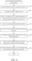
- FIG. 4 is a flowchart of the line-of-sight detection processing. This processing is executed by the distance calculation unit 8 reading a program recorded in a ROM (not shown in FIG. 1 ).
- step S401 when the line-of-sight detection processing starts, in step S401, the CPU 8a controls the light sources 9a and 9b to cause the light sources 9a and 9b to emit infrared light toward the eyeball 1 of the observer.
- the infrared light reflected by the eyeball 1 of the observer passes through the light-receiving lens 10, forms an image on the image sensor 11, and is photoelectrically converted. Thereby, a processable electrical signal of the eyeball image (eyeball image data) is obtained.
- step S402 the CPU 8a acquires eyeball image data obtained from the image sensor 11.
- step S403 the CPU 8a detects coordinates corresponding to corneal reflected images P1 and P2 of the light sources 9a and 9b and a coordinate corresponding to the pupil center 103 from the eyeball image data acquired in the step S402.
- the infrared light emitted from the light sources 9a and 9b illuminates the cornea 101 of the eyeball 1 of the observer.
- the corneal reflected images (Purkinje images) P1 and P2 formed by a part of the infrared light reflected on a surface of the cornea 101 are focused by the light-receiving lens 10 and formed on the image sensor 1 1 to become corneal reflected images P1' and P2'.
- light flux from an end of the pupil 102 also forms an image on the image sensor 11, and a pupil image 102' is formed.
- FIG. 3B shows the luminance distribution in the eyeball image of FIG. 3A .
- a horizontal direction of the eyeball image is an X axis
- a vertical direction of the eyeball image is a Y axis
- the luminance distribution in the X axis direction is shown.
- the coordinates of the corneal reflected images P1' and P2' in the X axis direction are X1 and X2
- the coordinates of the ends of the pupil image 102' in the X axis direction are Xa and Xb.
- an extremely high level of luminance is obtained at the coordinates X1 and X2 of the corneal reflected images P1' and P2'.
- a range larger than the coordinate Xa and smaller than the coordinate Xb which corresponds to a region of the pupil 102 (a region of the pupil image 102' obtained when the light flux from the pupil 102 forms an image on the image sensor 11)
- an extremely low level of luminance is obtained except for the coordinates X1 and X2.
- a luminance intermediate between the above two types of luminance is obtained.
- the X coordinates X1 and X2 of the corneal reflected images P1' and P2', and the X coordinates Xa and Xb of the ends of the pupil image 102' can be obtained.
- the coordinates with extremely high luminance can be obtained as the center-of-gravity coordinates of the corneal reflected images P1' and P2'
- the coordinates with extremely low luminance can be obtained as the coordinates of the pupil image 102'.
- a coordinate Xc of a pupil center image (a center of the pupil image 102') obtained when the light flux from the pupil center 103 forms an image on the image sensor 11 can be expressed as Xc ⁇ (Xa + Xb) / 2.
- the X coordinate Xc of the pupil center image can be calculated from the X coordinates Xa and Xb of the ends of the pupil image 102'. In this way, the X coordinates (X1, X2) of the corneal reflected images P 1' and P2', and the X coordinate (Xc) of the pupil center image can be estimated.
- the CPU 8a calculates an imaging magnification ⁇ of the eyeball image.
- the imaging magnification ⁇ is a magnification determined by a position of the eyeball 1 relative to the light-receiving lens 10, and can be determined as a function of a distance in the Z direction from the light-receiving lens 10 to the eyeball 1, a distance between the corneal reflected images P1' and P2' (X1 - X2), and a curvature of the cornea 101.
- step S405 the CPU 8a calculates the rotation angle of the optical axis of the eyeball 1 relative to the optical axis of the light-receiving lens 10.
- the X coordinate of the midpoint between the corneal reflected image P1 and the corneal reflected image P2 substantially matches the X coordinate of a center of curvature 104 of the cornea 101. For this reason, when a standard distance between the center of curvature 104 of the cornea 101 and the center 103 of the pupil 102 is Oc, the rotation angle ⁇ x of the eyeball 1 in the ZX plane (a plane perpendicular to the Y axis) can be calculated using the following equation (1).
- the rotation angle ⁇ y of the eyeball 1 in the ZY plane (a plane perpendicular to the X axis) can also be calculated in the same manner as the calculation method of the rotation angle ⁇ x.
- step S406 the CPU 8a acquires correction coefficient data (coefficient m and line-of-sight correction coefficients Ax, Bx, Ay, By) from the memory 8b.
- the coefficient m is a constant determined by the configuration of the observation apparatus 2 such as the arrangement of the eyepiece optical system 5 and the light-receiving lens 10, and is a conversion coefficient for converting the rotation angles ⁇ x and ⁇ y into the coordinate Xc corresponding to the pupil center 103 in a viewing image.
- the coefficient m is determined in advance and stored in the memory 8b.
- the line-of-sight correction coefficients Ax, Bx, Ay, and By are parameters for correcting individual differences in the eyeball 1, are obtained by performing a calibration work described later, and are stored in the memory 8b before the line-of-sight detection processing starts.
- step S407 the CPU 8a calculates a position of the observer's viewpoint (an estimated gazing point position (a gazing point direction)). Specifically, the estimated gazing point position is calculated using the rotation angles ⁇ x and ⁇ y of the eyeball 1 calculated in the step S405 and the correction coefficient data acquired in the step S406. Assuming that the coordinate (Hx, Hy) of the estimated gazing point position is the coordinate corresponding to the pupil center 103, the coordinate (Hx, Hy) of the estimated gazing point position is calculated using the following equations (2) and (3).
- Bx Hy m ⁇ Ay ⁇ ⁇ y +
- step S408 the CPU 8a stores the coordinate (Hx, Hy) of the estimated gazing point position calculated in the step S407 in the memory 8b, and ends the processing.
- the estimated gazing point position has been calculated.
- the CPU 8a (a calibration unit) performs the calibration work, acquires the line-of-sight correction coefficients Ax, Ay, Bx, By suitable for the user (the observer), and stores them in the memory 8b.
- the calibration work has been performed by displaying visual targets at positions such as the top, bottom, left, and right ends of a line-of-sight detection range before the line-of-sight detection processing, and having the observer look at the visual targets. Then, when the observer gazes at each visual target, the line-of-sight detection processing is performed, and a technique for determining the line-of-sight correction coefficients Ax, Ay, Bx, By suitable for the user from the calculated coordinates of a plurality of estimated gazing point positions and the coordinate of each visual target is known as a publicly known technique.
- the estimated gazing point position of the observer can be accurately calculated. Specifically, the acquisition coordinates X1 and X2 of the corneal reflected images P1' and P2' are affected by the eyeball position of the observer. As a result, it becomes difficult to calculate highly accurate results in subsequent calculations.
- FIG. 5 is a schematic diagram in a case where the image pickup unit 3 is arranged at an angle ⁇ e inclined to the optical axis 6 of the eyepiece optical system 5.
- the image pickup unit 3 is arranged as shown in FIG. 5 , when the eyeball 1 of the observer is displaced in the vertical direction relative to the optical axis 6 of the eyepiece optical system 5, a distance relationship between the image pickup unit 3 and the eyeball 1 effectively changes, although a distance between the eyeball 1 and the image pickup unit 3 in the Z direction remains constant.
- the distance between the image pickup unit 3 and the eyeball 1 cannot be calculated accurately, and it becomes difficult to accurately calculate the magnification of the image pickup unit 3.
- FIG. 5 is a schematic diagram in a case where the image pickup unit 3 is arranged at an angle ⁇ e inclined to the optical axis 6 of the eyepiece optical system 5.
- the eyeball image captured by the image pickup unit 3 is as shown in FIGs. 3A and 3B .
- the distance between the eyeball 1 and the image pickup unit 3 is substantially increased, so that the eyeball image captured by the image pickup unit 3 becomes as shown in FIG. 6 .
- the distance between the eyeball 1 and the image pickup unit 3 is substantially decreased, so that the eyeball image captured by the image pickup unit 3 becomes as shown in FIG. 7 .
- the CPU 8a uses correction information based on the positional information on the corneal reflected images P1' and P2' on the image to calculate the distance from the image pickup unit 3 to the eyeball 1 of the observer. Thereafter, the CPU 8a corrects the image captured by the image pickup unit 3 based on the calculated distance to the eyeball 1, and calculates the estimated gazing point position of the eyeball 1 by the above described method using the corrected image.
- FIG. 8 shows an example of the arrangement of the line-of-sight detecting apparatus 2a and the eyeball 1 of the observer in the correction information on this embodiment.
- the light source 9 illuminates the eyeball 1 of the observer, and a part of the light flux from the light source 9 is reflected at a position P on the cornea 101, and forms an image by the light-receiving lens 10 at a position P' on the image sensor 11.
- the light flux from the light source 9 passes through a principal point position 12 of the light-receiving lens 10 and forms an image at position P'.
- the light-receiving lens 10 is arranged obliquely relative to the optical axis 6 of the observation apparatus 2.
- the coordinate of the light source 9 be (xi, yi, zi)
- the coordinate of the principal point position 12 of the light-receiving lens 10 be (xp, yp, zp)
- the coordinate of the center of curvature 104 of the cornea 101 be (xc, yc, zc)
- the radius of the corneal sphere be Rc.
- the coordinate (hx, hy, hz) of the reflected image P' of the light source 9 formed on the image sensor 11 can be obtained from the relationship with the principal point position 12 of the light-receiving lens 10.
- the correction information may be based on at least one of the following for accuracy: the distance between the corneal reflected images (X1 - X2), the center-of-gravity coordinates of the corneal reflected images (center-of-gravity positions), the previously calculated positional relationship between the eyeball 1 and the image pickup unit 3, the radius of curvature Rc of the cornea 101, and the radius of curvature of the eyeball 1.
- the correction information may be based on the center-of-gravity coordinates of the corneal reflected images and the distance between the corneal reflected images (X1 - X2), and the correction information may be based on the previously calculated positional relationship between the eyeball 1 and the image pickup unit 3 and the radius of curvature of the eyeball 1.
- the radius of curvature Rc of the cornea 101 may be a fixed value or may be a curvature obtained by other means.
- the tilt angle ⁇ e of the optical axis of the image pickup unit 3 relative to the optical axis 6 of the observation optical system may satisfy the following inequality (4). 20 ° ⁇ ⁇ e ⁇ 70 °
- the light source 9 that emits infrared light has been described, but when the wavelength of the light source 9 that irradiates the eyeball 1 of the observer is ⁇ , the light source 9 may satisfy the following inequality (5). 800 nm ⁇ ⁇ ⁇ 1600 nm
- the memory 8b holds the correction information based on the positional information on the corneal reflected images P1' and P2' on the image. This enables accurate calculation of the distance to the eyeball 1 of the observer and provides the highly accurate line-of-sight detecting apparatus, even in a case where the distance (X1 - X2) between the corneal reflected images P1' and P2' changes due to positional movement of the eyeball 1 in a direction perpendicular to the optical axis 6 of the observation apparatus 2.
- this embodiment describes the case in which the image pickup unit 3 and the light-receiving lens 10 are arranged obliquely to the optical axis 6 of the observation apparatus 2, but this embodiment is not limited to this case.
- the distance (X1 - X2) between the corneal reflected images P 1' and P2' changes depending on positions of the corneal reflected images P1' and P2' on the image, even in a case where the distortion of the image pickup unit 3 is large. Even in such a case, if the correction information in this embodiment is retained, the highly accurate line-of-sight detecting apparatus can be provided.
- the distance to the eyeball 1 is calculated only once.
- the position of the eyeball 1 of the observer is basically fixed.
- the distance between the corneal reflected images is corrected using the correction information based on the positional information on the image, and thus the distance to the eyeball 1 can be calculated.
- the CPU 8a may correct the distance between the corneal reflected images at a predetermined time interval to calculate the distance to the eyeball 1, correct the image captured by the image pickup unit 3 based on the calculated distance to the eyeball 1, and use the corrected image to calculate the estimated gazing point position of the eyeball 1 in the above manner.
- the distance to the eyeball 1 of the observer is calculated based on the position and distance of the corneal reflected images P1' and P2'.
- the calculation of the distance to the eyeball 1 of the observer will also include errors due to an effect of various errors.
- it is effective to increase the number of the light sources 9 and calculate the distance to the eyeball 1 of the observer by combining the plurality of light sources.
- FIG. 9 illustrates an example of the eyeball image obtained during the line-of-sight detection in a case where there are four light sources 9.
- P3', P4', P5', and P6' are images in which the light fluxes from the light sources 9 are reflected at the position P of the cornea 101 and formed on the image sensor 11 by the light-receiving lens 10.
- a distance Pd3 between P3' and P4' and a distance Pd4 between P5' and P6' are obtained.
- Error factors that impair the accuracy of the line-of-sight detection are largely due to mechanical arrangement, and therefore often occur at a constant rate regardless of the distance between the corneal reflected images.
- the distance to the eyeball 1 may be calculated using the distance Pd4, which is a wider distance between the light sources.
- the distance to the eyeball 1 may be calculated using the plurality of distances in descending order of distance.
- the calculation of the distance to the eyeball 1 may be performed using a combination of the corneal reflected images P3' and P6' where the distance is maximum, or any other combination.
- the plurality of light source distances may be weighted and used to calculate the distance to the eyeball 1.
- the weighting may be performed based on reliability of the plurality of light source distances. Specifically, the higher the reliability, the greater the weighting may be applied to the light source distance.
- this embodiment shows a case where the distance to the eyeball 1 can be calculated with high accuracy by increasing the number of the light sources 9 and using the distances of the plurality of corneal reflected images.
- FIG. 10 is a schematic diagram of main parts of the image pickup apparatus 1000 including the observation apparatus 2 according to each embodiment.
- An object image formed by an image pickup optical system 1001 is converted into an electrical signal by an image sensor 1002, which is a photoelectric conversion element.
- an image sensor 1002 As the image sensor 1002, a CCD sensor, a CMOS sensor, or the like is used.
- An output signal from the image sensor 1002 is processed in an image processing circuit 1003 to form an image.
- the formed image is recorded on a recording medium 1004 such as a semiconductor memory, a magnetic tape, or an optical disk. Further, the image formed in the image processing circuit 1003 is displayed on an observation apparatus 1005, which is the observation apparatus according to each embodiment.
- Embodiment(s) of the disclosure can also be realized by a computer of a system or apparatus that reads out and executes computer-executable instructions (e.g., one or more programs) recorded on a storage medium (which may also be referred to more fully as a 'non-transitory computer-readable storage medium') to perform the functions of one or more of the above-described embodiment(s) and/or that includes one or more circuits (e.g., application specific integrated circuit (ASIC)) for performing the functions of one or more of the above-described embodiment(s), and by a method performed by the computer of the system or apparatus by, for example, reading out and executing the computer-executable instructions from the storage medium to perform the functions of one or more of the above-described embodiment(s) and/or controlling the one or more circuits to perform the functions of one or more of the above-described embodiment(s).
- ASIC application specific integrated circuit
- the computer may comprise one or more processors (e.g., central processing unit (CPU), micro processing unit (MPU)) and may include a network of separate computers or separate processors to read out and execute the computer-executable instructions.
- the computer-executable instructions may be provided to the computer, for example, from a network or the storage medium.
- the storage medium may include, for example, one or more of a hard disk, a random-access memory (RAM), a readonly memory (ROM), a storage of distributed computing systems, an optical disc (such as a compact disc (CD), digital versatile disc (DVD), or Blu-ray Disc (BD) TM ), a flash memory device, a memory card, and the like.
- Each embodiment can provide a line-of-sight detecting apparatus that has high detection accuracy by accurately calculating the distance to the observer's eyeball even if the position of the observer's eyeball changes.
Landscapes
- Engineering & Computer Science (AREA)
- Health & Medical Sciences (AREA)
- Physics & Mathematics (AREA)
- Life Sciences & Earth Sciences (AREA)
- General Physics & Mathematics (AREA)
- Theoretical Computer Science (AREA)
- General Health & Medical Sciences (AREA)
- Ophthalmology & Optometry (AREA)
- Biomedical Technology (AREA)
- Animal Behavior & Ethology (AREA)
- Veterinary Medicine (AREA)
- Biophysics (AREA)
- Public Health (AREA)
- Heart & Thoracic Surgery (AREA)
- Medical Informatics (AREA)
- Molecular Biology (AREA)
- Surgery (AREA)
- Multimedia (AREA)
- Computer Vision & Pattern Recognition (AREA)
- Human Computer Interaction (AREA)
- Optics & Photonics (AREA)
- Signal Processing (AREA)
- General Engineering & Computer Science (AREA)
- Geometry (AREA)
- Eye Examination Apparatus (AREA)
- Position Input By Displaying (AREA)
Abstract
Description
- One of the aspects of the embodiments relates to a line-of-sight detecting apparatus.
- A so-called line-of-sight detecting apparatus has conventionally been proposed that detect which position on an observation surface an observer of an optical apparatus is observing.
-
Japanese Patent Laid-Open No. 11-2755 - However, in a case where the observer's eyeball is imaged at a large angle from an oblique direction or in a case where the observer's eyeball is imaged from the front using an image pickup optical system with large distortion, the distance to the observer's eyeball cannot be accurately calculated using calculations based on the distance between Purkinje images.
- There are methods to reduce errors by performing calibration to adjust for individual differences among observers and environmental errors before performing line-of-sight detection, but in a case where a position of the observer's eyeball changes after the calibration, the accurate distance to the eyeball still cannot be calculated.
- The present invention in its first aspect provides a line-of-sight detecting apparatus as specified in
claims 1 to 14. - The present invention in its second aspect provides an observation apparatus as specified in claim 15.
- The present invention in its third aspect provides an image pickup apparatus as specified in claim 16.
- The present invention in its fourth aspect provides a control method as specified in claim 17.
- The present invention in its fifth aspect provides a program as specified in claim 18.
- Further features of various embodiments of the disclosure will become apparent from the following description of embodiments with reference to the attached drawings.
-
-
FIG. 1 is a schematic diagram of main parts of an observation apparatus according to a first embodiment. -
FIG. 2 explains the principle of a line-of-sight detecting method according to the first embodiment. -
FIGs. 3A and 3B illustrate an example of an eyeball image obtained during the line-of-sight detection. -
FIG. 4 is a flowchart of line-of-sight detection processing. -
FIG. 5 schematically illustrates changes in an eyeball position during the line-of-sight detection. -
FIG. 6 illustrates an example of an eyeball image obtained during the line-of-sight detection when the eyeball has moved to a position 1a inFIG. 5 . -
FIG. 7 illustrates an example of an eyeball image obtained during the line-of-sight detection when the eyeball has moved to a position 1b inFIG. 5 . -
FIG. 8 illustrates an example of an arrangement of a line-of-sight detecting apparatus according to the first embodiment and the observer's eyeball. -
FIG. 9 illustrates an example of an eyeball image obtained during line-of-sight detection according to a second embodiment. -
FIG. 10 schematically illustrates main parts of an image pickup apparatus. - In the following, the term "unit" may refer to a software context, a hardware context, or a combination of software and hardware contexts. In the software context, the term "unit" refers to a functionality, an application, a software module, a function, a routine, a set of instructions, or a program that can be executed by a programmable processor such as a microprocessor, a central processing unit (CPU), or a specially designed programmable device or controller. A memory contains instructions or programs that, when executed by the CPU, cause the CPU to perform operations corresponding to units or functions. In the hardware context, the term "unit" refers to a hardware element, a circuit, an assembly, a physical structure, a system, a module, or a subsystem. Depending on the specific embodiment, the term "unit" may include mechanical, optical, or electrical components, or any combination of them. The term "unit" may include active (e.g., transistors) or passive (e.g., capacitor) components. The term "unit" may include semiconductor devices having a substrate and other layers of materials having various concentrations of conductivity. It may include a CPU or a programmable processor that can execute a program stored in a memory to perform specified functions. The term "unit" may include logic elements (e.g., AND, OR) implemented by transistor circuits or any other switching circuits. In the combination of software and hardware contexts, the term "unit" or "circuit" refers to any combination of the software and hardware contexts as described above. In addition, the term "element," "assembly," "component," or "device" may also refer to "circuit" with or without integration with packaging materials.
- Referring now to the accompanying drawings, a detailed description will be given of embodiments according to the disclosure. Corresponding elements in respective figures will be designated by the same reference numerals, and a duplicate description thereof will be omitted.
- Referring to
FIG. 1 , anobservation apparatus 2 including a line-of-sight detecting apparatus 2a according to a first embodiment will be described.FIG. 1 is a schematic diagram of theobservation apparatus 2 according to the first embodiment. Theobservation apparatus 2 includes animage display element 7, an eyepieceoptical system 5, animage pickup unit 3,light sources distance calculation unit 8. The line-of-sight detecting apparatus 2a includes theimage pickup unit 3, thelight sources distance calculation unit 8. Theimage display element 7 is, for example, a liquid crystal display element, an organic EL display, or the like. The eyepieceoptical system 5 guides an image displayed on theimage display element 7 to aneyeball 1 of an observer. Theimage pickup unit 3 includes an image pickup optical system and an image sensor, and captures an image of theeyeball 1 of the observer. Thelight sources eyeball 1 of the observer who observes theobservation apparatus 2 from positions different from each other. The distance calculation unit (a calculation unit) 8 calculates a distance from theimage pickup unit 3 to theeyeball 1 of the observer (an eyeball distance) based on a distance between reflected images of thelight sources eyeball 1 in the image captured by theimage pickup unit 3. - The
image pickup unit 3 is arranged obliquely relative to anoptical axis 6 of the eyepiece optical system 5 (anoptical axis 6 of the observation apparatus 2). In other words, theoptical axis 6 of the eyepieceoptical system 5 and an optical axis of the image pickup optical system of theimage pickup unit 3 are not parallel to each other. Theimage pickup unit 3 captures the image of theeyeball 1 of the observer from an oblique direction relative to theoptical axis 6 of the eyepieceoptical system 5. Thelight sources light sources distance calculation unit 8 includes aCPU 8a which is a central processing unit of a microcomputer that controls theentire observation apparatus 2, and amemory 8b that stores an image pickup result of theimage pickup unit 3, line-of-sight correction data for correcting individual differences in line of sight, which will be described later, and correction information based on positional information on the image, which will be described later. In this embodiment, thedistance calculation unit 8 calculates the distance from theimage pickup unit 3 to theeyeball 1 using the correction information based on the positional information on the image. - Next, referring to
FIGs. 2-4 , an operation of the line-of-sight detection will be explained. -
FIG. 2 explains the principle of the line-of-sight detection. Thelight sources lens 10, and illuminate theeyeball 1 of the observer who observes theobservation apparatus 2 from positions different from each other. A part of illumination light emitted from thelight sources eyeball 1 of the observer is focused by the light-receivinglens 10 onto animage sensor 11 for capturing an image of theeyeball 1. InFIG. 2 , thereference numeral 101 denotes a cornea of theeyeball 1 of the observer, thereference numeral 102 denotes a pupil, thereference numeral 103 denotes a center of the pupil 103 (a pupil center), thereference numeral 104 denotes a center of curvature of thecornea 101, thereference numeral 105 denotes a center position of a rotation of theeyeball 1, and thereference numeral 106 denotes a rotation angle of theeyeball 1 relative to the optical axis. -
FIG. 3A is a schematic diagram of the image of the eyeball 1 (an eyeball image) captured by theimage sensor 11.FIG. 3B is a diagram showing luminance distribution in the eyeball image acquired by theimage sensor 11. -
FIG. 4 is a flowchart of the line-of-sight detection processing. This processing is executed by thedistance calculation unit 8 reading a program recorded in a ROM (not shown inFIG. 1 ). - In
FIG. 4 , when the line-of-sight detection processing starts, in step S401, theCPU 8a controls thelight sources light sources eyeball 1 of the observer. The infrared light reflected by theeyeball 1 of the observer passes through the light-receivinglens 10, forms an image on theimage sensor 11, and is photoelectrically converted. Thereby, a processable electrical signal of the eyeball image (eyeball image data) is obtained. - In step S402, the
CPU 8a acquires eyeball image data obtained from theimage sensor 11. - In step S403, the
CPU 8a detects coordinates corresponding to corneal reflected images P1 and P2 of thelight sources pupil center 103 from the eyeball image data acquired in the step S402. - The infrared light emitted from the
light sources cornea 101 of theeyeball 1 of the observer. At this time, the corneal reflected images (Purkinje images) P1 and P2 formed by a part of the infrared light reflected on a surface of thecornea 101 are focused by the light-receivinglens 10 and formed on theimage sensor 1 1 to become corneal reflected images P1' and P2'. Similarly, light flux from an end of thepupil 102 also forms an image on theimage sensor 11, and a pupil image 102' is formed. -
FIG. 3B shows the luminance distribution in the eyeball image ofFIG. 3A . InFIG. 3B , a horizontal direction of the eyeball image is an X axis, a vertical direction of the eyeball image is a Y axis, and the luminance distribution in the X axis direction is shown. In this embodiment, the coordinates of the corneal reflected images P1' and P2' in the X axis direction (the horizontal direction) are X1 and X2, and the coordinates of the ends of the pupil image 102' in the X axis direction are Xa and Xb. As shown inFIG. 3B , an extremely high level of luminance is obtained at the coordinates X1 and X2 of the corneal reflected images P1' and P2'. In a range larger than the coordinate Xa and smaller than the coordinate Xb, which corresponds to a region of the pupil 102 (a region of the pupil image 102' obtained when the light flux from thepupil 102 forms an image on the image sensor 11), an extremely low level of luminance is obtained except for the coordinates X1 and X2. On the other hand, in a region 107' of an iris part outside thepupil 102, a luminance intermediate between the above two types of luminance is obtained. Specifically, in a region where the X coordinate (coordinate in the X axis direction) is smaller than the coordinate Xa, and in a region where the X coordinate is larger than the coordinate Xb, a luminance intermediate between the above two types of luminance is obtained. - From the luminance distribution as shown in
FIG. 3B , the X coordinates X1 and X2 of the corneal reflected images P1' and P2', and the X coordinates Xa and Xb of the ends of the pupil image 102' can be obtained. Specifically, the coordinates with extremely high luminance can be obtained as the center-of-gravity coordinates of the corneal reflected images P1' and P2', and the coordinates with extremely low luminance can be obtained as the coordinates of the pupil image 102'. - Furthermore, in a case where a
rotation angle 106 of the optical axis of theeyeball 1 relative to the optical axis of the light-receivinglens 10 is small, a coordinate Xc of a pupil center image (a center of the pupil image 102') obtained when the light flux from thepupil center 103 forms an image on theimage sensor 11 can be expressed as Xc ≈ (Xa + Xb) / 2. In other words, the X coordinate Xc of the pupil center image can be calculated from the X coordinates Xa and Xb of the ends of the pupil image 102'. In this way, the X coordinates (X1, X2) of the corneal reflected images P 1' and P2', and the X coordinate (Xc) of the pupil center image can be estimated. - Returning back to
FIG. 4 , in step S404, theCPU 8a calculates an imaging magnification β of the eyeball image. The imaging magnification β is a magnification determined by a position of theeyeball 1 relative to the light-receivinglens 10, and can be determined as a function of a distance in the Z direction from the light-receivinglens 10 to theeyeball 1, a distance between the corneal reflected images P1' and P2' (X1 - X2), and a curvature of thecornea 101. - In step S405, the
CPU 8a calculates the rotation angle of the optical axis of theeyeball 1 relative to the optical axis of the light-receivinglens 10. The X coordinate of the midpoint between the corneal reflected image P1 and the corneal reflected image P2 substantially matches the X coordinate of a center ofcurvature 104 of thecornea 101. For this reason, when a standard distance between the center ofcurvature 104 of thecornea 101 and thecenter 103 of thepupil 102 is Oc, the rotation angle θx of theeyeball 1 in the ZX plane (a plane perpendicular to the Y axis) can be calculated using the following equation (1). The rotation angle θy of theeyeball 1 in the ZY plane (a plane perpendicular to the X axis) can also be calculated in the same manner as the calculation method of the rotation angle θx.
- In step S406, the
CPU 8a acquires correction coefficient data (coefficient m and line-of-sight correction coefficients Ax, Bx, Ay, By) from thememory 8b. The coefficient m is a constant determined by the configuration of theobservation apparatus 2 such as the arrangement of the eyepieceoptical system 5 and the light-receivinglens 10, and is a conversion coefficient for converting the rotation angles θx and θy into the coordinate Xc corresponding to thepupil center 103 in a viewing image. The coefficient m is determined in advance and stored in thememory 8b. Furthermore, the line-of-sight correction coefficients Ax, Bx, Ay, and By are parameters for correcting individual differences in theeyeball 1, are obtained by performing a calibration work described later, and are stored in thememory 8b before the line-of-sight detection processing starts. - In step S407, the
CPU 8a calculates a position of the observer's viewpoint (an estimated gazing point position (a gazing point direction)). Specifically, the estimated gazing point position is calculated using the rotation angles θx and θy of theeyeball 1 calculated in the step S405 and the correction coefficient data acquired in the step S406. Assuming that the coordinate (Hx, Hy) of the estimated gazing point position is the coordinate corresponding to thepupil center 103, the coordinate (Hx, Hy) of the estimated gazing point position is calculated using the following equations (2) and (3).

- In step S408, the
CPU 8a stores the coordinate (Hx, Hy) of the estimated gazing point position calculated in the step S407 in thememory 8b, and ends the processing. - As described above, in the line-of-sight detection processing according to this embodiment, using the rotation angles θx and θy of the
eyeball 1, and the correction coefficient data (the coefficient m, and the line-of-sight correction coefficients Ax, Bx, Ay, By), the estimated gazing point position has been calculated. - However, due to factors such as individual differences in a shape of the
eyeball 1 of a human, the estimated gazing point position may not be estimated with high accuracy. Therefore, before performing the line-of-sight detection processing for the observer, theCPU 8a (a calibration unit) performs the calibration work, acquires the line-of-sight correction coefficients Ax, Ay, Bx, By suitable for the user (the observer), and stores them in thememory 8b. - Conventionally, the calibration work has been performed by displaying visual targets at positions such as the top, bottom, left, and right ends of a line-of-sight detection range before the line-of-sight detection processing, and having the observer look at the visual targets. Then, when the observer gazes at each visual target, the line-of-sight detection processing is performed, and a technique for determining the line-of-sight correction coefficients Ax, Ay, Bx, By suitable for the user from the calculated coordinates of a plurality of estimated gazing point positions and the coordinate of each visual target is known as a publicly known technique.
- However, in the calculations in the steps S403 to S407, in a case where the
image pickup unit 3 is arranged obliquely to theoptical axis 6 of the eyepieceoptical system 5 as in this embodiment, the estimated gazing point position of the observer can be accurately calculated. Specifically, the acquisition coordinates X1 and X2 of the corneal reflected images P1' and P2' are affected by the eyeball position of the observer. As a result, it becomes difficult to calculate highly accurate results in subsequent calculations. -
FIG. 5 is a schematic diagram in a case where theimage pickup unit 3 is arranged at an angle θe inclined to theoptical axis 6 of the eyepieceoptical system 5. In a case where theimage pickup unit 3 is arranged as shown inFIG. 5 , when theeyeball 1 of the observer is displaced in the vertical direction relative to theoptical axis 6 of the eyepieceoptical system 5, a distance relationship between theimage pickup unit 3 and theeyeball 1 effectively changes, although a distance between theeyeball 1 and theimage pickup unit 3 in the Z direction remains constant. As a result, the distance between theimage pickup unit 3 and theeyeball 1 cannot be calculated accurately, and it becomes difficult to accurately calculate the magnification of theimage pickup unit 3. For example, inFIG. 5 , in a case where theeyeball 1 is placed on the optical axis, the eyeball image captured by theimage pickup unit 3 is as shown inFIGs. 3A and 3B . However, in a case where theeyeball 1 is placed at the position 1a, the distance between theeyeball 1 and theimage pickup unit 3 is substantially increased, so that the eyeball image captured by theimage pickup unit 3 becomes as shown inFIG. 6 . Similarly, in a case where theeyeball 1 is placed at the position 1b, the distance between theeyeball 1 and theimage pickup unit 3 is substantially decreased, so that the eyeball image captured by theimage pickup unit 3 becomes as shown inFIG. 7 . - When the distances between the corneal reflected images obtained in
FIGs. 6 and7 are respectively Pd1 and Pd2, and if Pd1 = Pd2, the calculation results in the steps S403 and S404 inFIG. 4 will be the same inFIGs. 6 and7 . However, as is clear fromFIGs. 6 and7 , the magnification of theeyeball 1 of the observer is actually significantly different, which means that the distance to theeyeball 1 of the observer cannot be calculated accurately. - There is a method of adjusting these errors by performing the calibration to improve the accuracy of line-of-sight detection, but in a case where the positional relationship between the
eyeball 1 of the observer and theimage pickup unit 3 changes, an accurate calculation becomes difficult. This makes it difficult to ensure sufficient line-of-sight detection accuracy. - In order to deal with these problems, in this embodiment, the
CPU 8a uses correction information based on the positional information on the corneal reflected images P1' and P2' on the image to calculate the distance from theimage pickup unit 3 to theeyeball 1 of the observer. Thereafter, theCPU 8a corrects the image captured by theimage pickup unit 3 based on the calculated distance to theeyeball 1, and calculates the estimated gazing point position of theeyeball 1 by the above described method using the corrected image. - The correction information based on the positional information on the corneal reflected images P1' and P2' on the image will be explained in detail using
FIG. 8. FIG. 8 shows an example of the arrangement of the line-of-sight detecting apparatus 2a and theeyeball 1 of the observer in the correction information on this embodiment. Thelight source 9 illuminates theeyeball 1 of the observer, and a part of the light flux from thelight source 9 is reflected at a position P on thecornea 101, and forms an image by the light-receivinglens 10 at a position P' on theimage sensor 11. The light flux from thelight source 9 passes through aprincipal point position 12 of the light-receivinglens 10 and forms an image at position P'. The light-receivinglens 10 is arranged obliquely relative to theoptical axis 6 of theobservation apparatus 2. - Let the coordinate of the
light source 9 be (xi, yi, zi), the coordinate of theprincipal point position 12 of the light-receivinglens 10 be (xp, yp, zp), the coordinate of the center ofcurvature 104 of thecornea 101 be (xc, yc, zc), and the radius of the corneal sphere be Rc. At this time, the coordinate (xr, yr, zr) of the reflection point P on thecornea 101 of the light flux emitted from thelight source 9 is uniquely determined. Once the coordinate of the reflection point P of thecornea 101 is obtained, the coordinate (hx, hy, hz) of the reflected image P' of thelight source 9 formed on theimage sensor 11 can be obtained from the relationship with theprincipal point position 12 of the light-receivinglens 10. - Direct calculation of the coordinate of the reflection point P becomes very complicated. For this reason, a calculation is performed after setting multiple positional relationships between the position of the
eyeball 1 and theimage pickup unit 3 in advance, the calculation result is retained in thememory 8b as the correction information, and a correction is made to the coordinate (hx, hy, hz) of the reflected image P' of thelight source 9 using the correction information. the correction information may be based on at least one of the following for accuracy: the distance between the corneal reflected images (X1 - X2), the center-of-gravity coordinates of the corneal reflected images (center-of-gravity positions), the previously calculated positional relationship between theeyeball 1 and theimage pickup unit 3, the radius of curvature Rc of thecornea 101, and the radius of curvature of theeyeball 1. The correction information may be based on the center-of-gravity coordinates of the corneal reflected images and the distance between the corneal reflected images (X1 - X2), and the correction information may be based on the previously calculated positional relationship between theeyeball 1 and theimage pickup unit 3 and the radius of curvature of theeyeball 1. At this time, the radius of curvature Rc of thecornea 101 may be a fixed value or may be a curvature obtained by other means. - In the line-of-sight detecting apparatus according to this example, the tilt angle θe of the optical axis of the
image pickup unit 3 relative to theoptical axis 6 of the observation optical system may satisfy the following inequality (4).
- In a case where the value becomes lower than the lower limit of the inequality (4), a certain level of line-of-sight detection accuracy can be obtained even without the correction information as in this embodiment. For this reason, having the correction information as in this embodiment unnecessarily burdens the
CPU 8a and thememory 8b. In a case where the value becomes larger than the upper limit of the inequality (4), it becomes difficult for theimage pickup unit 3 to obtain the corneal reflected image from thelight source 9 due to the eyelids of the observer, and it has an adverse effect on the accuracy of line-of-sight detection. - Furthermore, in this embodiment, the
light source 9 that emits infrared light has been described, but when the wavelength of thelight source 9 that irradiates theeyeball 1 of the observer is λ, thelight source 9 may satisfy the following inequality (5).
- In a case where the value becomes lower than the lower limit of the inequality (5), it is undesirable because it is more likely to be visible to the observer and thus causes discomfort to the observer. In a case where the value becomes larger than the upper limit of the inequality (5), light is absorbed in a plastic material used for the eyepiece
optical system 5 and glasses of the observer, which is undesirable. - In this embodiment, the
memory 8b holds the correction information based on the positional information on the corneal reflected images P1' and P2' on the image. This enables accurate calculation of the distance to theeyeball 1 of the observer and provides the highly accurate line-of-sight detecting apparatus, even in a case where the distance (X1 - X2) between the corneal reflected images P1' and P2' changes due to positional movement of theeyeball 1 in a direction perpendicular to theoptical axis 6 of theobservation apparatus 2. - As explained above, this embodiment describes the case in which the
image pickup unit 3 and the light-receivinglens 10 are arranged obliquely to theoptical axis 6 of theobservation apparatus 2, but this embodiment is not limited to this case. For example, the distance (X1 - X2) between the corneal reflected images P 1' and P2' changes depending on positions of the corneal reflected images P1' and P2' on the image, even in a case where the distortion of theimage pickup unit 3 is large. Even in such a case, if the correction information in this embodiment is retained, the highly accurate line-of-sight detecting apparatus can be provided. - In this embodiment, an example in which the distance to the
eyeball 1 is calculated only once has been described. In a line-of-sight detection in VR, etc., the position of theeyeball 1 of the observer is basically fixed. For this reason, first, the distance between the corneal reflected images is corrected using the correction information based on the positional information on the image, and thus the distance to theeyeball 1 can be calculated. However, in a case where the position of the observer's eye changes, it is necessary to correct the distance between the corneal reflected images in real time and calculate the distance to theeyeball 1 before performing the line-of-sight detection. In this case, theCPU 8a may correct the distance between the corneal reflected images at a predetermined time interval to calculate the distance to theeyeball 1, correct the image captured by theimage pickup unit 3 based on the calculated distance to theeyeball 1, and use the corrected image to calculate the estimated gazing point position of theeyeball 1 in the above manner. - In the first embodiment, an embodiment has been shown in which the highly accurate line-of-sight detection can be performed by holding the correction information based on the positional information on the image. In this embodiment, an embodiment for providing a more accurate line-of-sight detection function will be described.
- In the first embodiment, an example has been shown in which the distance to the
eyeball 1 of the observer is calculated based on the position and distance of the corneal reflected images P1' and P2'. However, in reality, there is a possibility that the calculation of the distance to theeyeball 1 of the observer will also include errors due to an effect of various errors. In such a case, in order to further improve an accuracy, it is effective to increase the number of thelight sources 9 and calculate the distance to theeyeball 1 of the observer by combining the plurality of light sources. -
FIG. 9 illustrates an example of the eyeball image obtained during the line-of-sight detection in a case where there are fourlight sources 9. P3', P4', P5', and P6' are images in which the light fluxes from thelight sources 9 are reflected at the position P of thecornea 101 and formed on theimage sensor 11 by the light-receivinglens 10. In such a case, for example, a distance Pd3 between P3' and P4' and a distance Pd4 between P5' and P6' are obtained. Error factors that impair the accuracy of the line-of-sight detection are largely due to mechanical arrangement, and therefore often occur at a constant rate regardless of the distance between the corneal reflected images. Therefore, in a case where the eyeball image as shown inFIG. 9 is acquired, the distance to theeyeball 1 may be calculated using the distance Pd4, which is a wider distance between the light sources. In this way, by preferentially using the wider distance of the plurality of distances to calculate the distance to theeyeball 1, it is more likely that the observer's gazing point direction can be calculated with high accuracy. For example, the distance to theeyeball 1 may be calculated using the plurality of distances in descending order of distance. - Although only the light source distances Pd3 and Pd4 are illustrated in
FIG. 9 , the calculation of the distance to theeyeball 1 may be performed using a combination of the corneal reflected images P3' and P6' where the distance is maximum, or any other combination. In a case where the plurality of light source distances are obtained, they may be weighted and used to calculate the distance to theeyeball 1. The weighting may be performed based on reliability of the plurality of light source distances. Specifically, the higher the reliability, the greater the weighting may be applied to the light source distance. - As described above, this embodiment shows a case where the distance to the
eyeball 1 can be calculated with high accuracy by increasing the number of thelight sources 9 and using the distances of the plurality of corneal reflected images. - Next, an embodiment according to an
image pickup apparatus 1000 using theobservation apparatus 2 shown in each embodiment will be described with reference toFIG. 10. FIG. 10 is a schematic diagram of main parts of theimage pickup apparatus 1000 including theobservation apparatus 2 according to each embodiment. An object image formed by an image pickupoptical system 1001 is converted into an electrical signal by animage sensor 1002, which is a photoelectric conversion element. As theimage sensor 1002, a CCD sensor, a CMOS sensor, or the like is used. - An output signal from the
image sensor 1002 is processed in animage processing circuit 1003 to form an image. The formed image is recorded on arecording medium 1004 such as a semiconductor memory, a magnetic tape, or an optical disk. Further, the image formed in theimage processing circuit 1003 is displayed on anobservation apparatus 1005, which is the observation apparatus according to each embodiment. - Embodiment(s) of the disclosure can also be realized by a computer of a system or apparatus that reads out and executes computer-executable instructions (e.g., one or more programs) recorded on a storage medium (which may also be referred to more fully as a 'non-transitory computer-readable storage medium') to perform the functions of one or more of the above-described embodiment(s) and/or that includes one or more circuits (e.g., application specific integrated circuit (ASIC)) for performing the functions of one or more of the above-described embodiment(s), and by a method performed by the computer of the system or apparatus by, for example, reading out and executing the computer-executable instructions from the storage medium to perform the functions of one or more of the above-described embodiment(s) and/or controlling the one or more circuits to perform the functions of one or more of the above-described embodiment(s). The computer may comprise one or more processors (e.g., central processing unit (CPU), micro processing unit (MPU)) and may include a network of separate computers or separate processors to read out and execute the computer-executable instructions. The computer-executable instructions may be provided to the computer, for example, from a network or the storage medium. The storage medium may include, for example, one or more of a hard disk, a random-access memory (RAM), a readonly memory (ROM), a storage of distributed computing systems, an optical disc (such as a compact disc (CD), digital versatile disc (DVD), or Blu-ray Disc (BD)™), a flash memory device, a memory card, and the like.
- While the disclosure has described example embodiments, it is to be understood that some embodiments are not limited to the disclosed embodiments. The scope of the following claims is to be accorded the broadest interpretation so as to encompass all such modifications and equivalent structures and functions.
- Each embodiment can provide a line-of-sight detecting apparatus that has high detection accuracy by accurately calculating the distance to the observer's eyeball even if the position of the observer's eyeball changes.
Claims (18)
- A line-of-sight detecting apparatus (2a) comprising:a plurality of light sources including a first light source (4a) and a second light source (4b), and configured to illuminate an eyeball (1) of a user who observes an observation apparatus (2), from positions different from each other;an image pickup unit (3) configured to capture an image of the eyeball; anda calculator (8) configured to calculate an eyeball distance from the image pickup unit to the eyeball based on a distance, in the image captured by the image pickup unit, between a first reflected image of the first light source reflected by the eyeball and a second reflected image of the second light source reflected by the eyeball,characterized in that the calculator calculates the eyeball distance using correction information based on positional information on the first reflected image and the second reflected image on the image.
- The line-of-sight detecting apparatus according to claim 1, characterized in that the image pickup unit captures the image from an oblique direction relative to an optical axis of the observation apparatus.
- The line-of-sight detecting apparatus according to claim 2, characterized in that the following inequality is satisfied:

- The line-of-sight detecting apparatus according to any one of claims 1 to 3, characterized in that the correction information is based on at least one of a center-of-gravity coordinate of a plurality of reflected images of the plurality of light sources reflected by the eyeball in the image, a distance between the plurality of reflected images in the image, a previously calculated positional relationship between a position of the eyeball and the image pickup unit, and a radius of curvature of the eyeball.
- The line-of-sight detecting apparatus according to any one of claims 1 to 4, characterized in that the correction information is based on a center-of-gravity coordinate of a plurality of reflected images of the plurality of light sources reflected by the eyeball in the image, and a distance between the plurality of reflected images in the image.
- The line-of-sight detecting apparatus according to any one of claims 1 to 5, characterized in that the correction information is based on a previously calculated positional relationship between a position of the eyeball and the image pickup unit, and a radius of curvature of the eyeball
- The line-of-sight detecting apparatus according to any one of claims 1 to 6, characterized in that the calculator weights a plurality of distances between reflected images obtained from a plurality of reflected images of the plurality of light sources reflected by the eyeball.
- The line-of-sight detecting apparatus according to claim 7, characterized in that the calculator weights the plurality of distances based on reliability of the plurality of distances.
- The line-of-sight detecting apparatus according to any one of claims 1 to 8, characterized in that the calculator preferentially uses a wide distance among a plurality of distances between reflected images obtained from a plurality of reflected images of the plurality of light sources reflected by the eyeball.
- The line-of-sight detecting apparatus according to any one of claims 1 to 9, characterized in that the calculator uses a maximum distance among a plurality of distances between reflected images obtained from a plurality of reflected images of the plurality of light sources reflected by the eyeball.
- The line-of-sight detecting apparatus according to any one of claims 1 to 10, characterized in that the calculator calculates the eyeball distance at a predetermined time interval, corrects the image captured by the image pickup unit based on the calculated eyeball distance, and calculates a gazing point direction of the eyeball of the user using the corrected image.
- The line-of-sight detecting apparatus according to any one of claims 1 to 11, characterized in that the following inequality is satisfied:

- The line-of-sight detecting apparatus according to any one of claims 1 to 12, characterized in that the calculator corrects the distance between the first reflected image of the first light source reflected by the eyeball and the second reflected image of the second light source reflected by the eyeball, using the correction information.
- The line-of-sight detecting apparatus according to any one of claims 1 to 13, further comprising a memory storing the correction information.
- An observation apparatus (2) comprising:an image display element (7); andthe line-of-sight detecting apparatus (2a) according to any one of claims 1 to 14, which is used to observe an image displayed on the image display element.
- An image pickup apparatus (1000) comprising:an image pickup optical system;an image sensor (1002) configured to capture an object image formed via the image pickup optical system; andthe observation apparatus (2) according to claim 15.
- A control method of a line-of-sight detecting apparatus (2a) including a plurality of light sources including a first light source (4a) and a second light source (4b), and configured to illuminate an eyeball (1) of a user who observes an observation apparatus, from different positions from each other, and an image pickup unit (3) configured to capture an image of the eyeball, the control method comprising:an image capturing step of capturing the image of the eyeball;a calculating step of calculating an eyeball distance from the image pickup unit to the eyeball based on a distance between a first reflected image of the first light source reflected by the eyeball and a second reflected image of the second light source reflected by the eyeball in the image captured by the image capturing step,characterized in that the calculating step calculates the eyeball distance using correction information based on positional information on the first reflected image and the second reflected image on the image.
- A program to cause a computer to execute a control method according to claim 17.
Applications Claiming Priority (1)
| Application Number | Priority Date | Filing Date | Title |
|---|---|---|---|
| JP2023014904A JP2024110353A (en) | 2023-02-02 | 2023-02-02 | Line-of-sight detection device, observation device, imaging device, control method, and program |
Publications (1)
| Publication Number | Publication Date |
|---|---|
| EP4410182A1 true EP4410182A1 (en) | 2024-08-07 |
Family
ID=89767781
Family Applications (1)
| Application Number | Title | Priority Date | Filing Date |
|---|---|---|---|
| EP24154382.6A Pending EP4410182A1 (en) | 2023-02-02 | 2024-01-29 | Line-of-sight detecting apparatus, observation apparatus, image pickup apparatus, control method, and program |
Country Status (4)
| Country | Link |
|---|---|
| US (1) | US20240265566A1 (en) |
| EP (1) | EP4410182A1 (en) |
| JP (1) | JP2024110353A (en) |
| CN (1) | CN118415581A (en) |
Citations (4)
| Publication number | Priority date | Publication date | Assignee | Title |
|---|---|---|---|---|
| JPH112755A (en) | 1997-06-10 | 1999-01-06 | Nikon Corp | Gaze detection method and gaze detection device |
| WO2022038815A1 (en) * | 2020-08-20 | 2022-02-24 | 株式会社Jvcケンウッド | Distance calculation device, distance calculation method, and distance calculation program |
| US20220197111A1 (en) * | 2020-12-18 | 2022-06-23 | Canon Kabushiki Kaisha | Gaze detection apparatus, gaze detection method, and non-transitory computer readable medium |
| US20220277590A1 (en) * | 2021-02-26 | 2022-09-01 | Canon Kabushiki Kaisha | Line-of-sight detection device and control method for controlling the same |
Family Cites Families (2)
| Publication number | Priority date | Publication date | Assignee | Title |
|---|---|---|---|---|
| JP3834636B2 (en) * | 2002-11-22 | 2006-10-18 | 独立行政法人産業技術総合研究所 | Method and system for correcting deviation of head movement in gaze position measurement |
| JP5241878B2 (en) * | 2011-03-31 | 2013-07-17 | キヤノン株式会社 | Ophthalmic system, ophthalmic apparatus, control method, and program |
-
2023
- 2023-02-02 JP JP2023014904A patent/JP2024110353A/en active Pending
-
2024
- 2024-01-29 EP EP24154382.6A patent/EP4410182A1/en active Pending
- 2024-01-30 CN CN202410126421.2A patent/CN118415581A/en active Pending
- 2024-01-31 US US18/428,067 patent/US20240265566A1/en active Pending
Patent Citations (4)
| Publication number | Priority date | Publication date | Assignee | Title |
|---|---|---|---|---|
| JPH112755A (en) | 1997-06-10 | 1999-01-06 | Nikon Corp | Gaze detection method and gaze detection device |
| WO2022038815A1 (en) * | 2020-08-20 | 2022-02-24 | 株式会社Jvcケンウッド | Distance calculation device, distance calculation method, and distance calculation program |
| US20220197111A1 (en) * | 2020-12-18 | 2022-06-23 | Canon Kabushiki Kaisha | Gaze detection apparatus, gaze detection method, and non-transitory computer readable medium |
| US20220277590A1 (en) * | 2021-02-26 | 2022-09-01 | Canon Kabushiki Kaisha | Line-of-sight detection device and control method for controlling the same |
Also Published As
| Publication number | Publication date |
|---|---|
| CN118415581A (en) | 2024-08-02 |
| US20240265566A1 (en) | 2024-08-08 |
| JP2024110353A (en) | 2024-08-15 |
Similar Documents
| Publication | Publication Date | Title |
|---|---|---|
| JP6586523B2 (en) | Eye tracking using structured light | |
| US9244529B2 (en) | Point-of-gaze estimation robust to head rotations and/or device rotations | |
| CN119257539A (en) | Reliability of left and right eye gaze tracking data | |
| WO2012077713A1 (en) | Method for detecting point of gaze and device for detecting point of gaze | |
| US20210092284A1 (en) | Information processing device, information processing method, and program | |
| JP7081599B2 (en) | Information processing equipment, information processing methods, and programs | |
| US12118145B2 (en) | Electronic apparatus | |
| JP2803222B2 (en) | Eye gaze detection device | |
| Mastrangelo et al. | A low-profile digital eye-tracking oculometer for smart eyeglasses | |
| US8567949B2 (en) | Ophthalmic device and method | |
| CN120225111A (en) | Image Correction for Ophthalmic Imaging Systems | |
| US12401886B2 (en) | Electronic device, control method, and non-transitory computer readable medium | |
| US12367710B2 (en) | Line-of-sight detection device and control method for controlling the same | |
| EP4410182A1 (en) | Line-of-sight detecting apparatus, observation apparatus, image pickup apparatus, control method, and program | |
| US20230092593A1 (en) | Detection device detecting gaze point of user, control method therefor, and storage medium storing control program therefor | |
| JPH02189128A (en) | Optical device with gaze point detection means | |
| US12432439B2 (en) | Line-of-sight detecting apparatus, image pickup apparatus, line-of-sight detecting method, and storage medium | |
| CN114650350A (en) | Gaze detection device, gaze detection method, and computer-readable storage medium | |
| US20230236666A1 (en) | Optical apparatus, image pickup apparatus, control method of optical apparatus, and storage medium | |
| JP2015046111A (en) | Viewpoint detection device and viewpoint detection method | |
| US20230236407A1 (en) | Method for adjusting and/or calibrating a medical microscope and medical microscope | |
| US12300130B2 (en) | Image processing apparatus, display apparatus, image processing method, and storage medium | |
| JP2023074878A (en) | Line-of-sight detection device, control method and program for line-of-sight detection device | |
| US20240288698A1 (en) | Electronic Devices with User-Specific Models | |
| TWI800959B (en) | Eye tracking method and eye tracking device |
Legal Events
| Date | Code | Title | Description |
|---|---|---|---|
| PUAI | Public reference made under article 153(3) epc to a published international application that has entered the european phase |
Free format text: ORIGINAL CODE: 0009012 |
|
| STAA | Information on the status of an ep patent application or granted ep patent |
Free format text: STATUS: THE APPLICATION HAS BEEN PUBLISHED |
|
| AK | Designated contracting states |
Kind code of ref document: A1 Designated state(s): AL AT BE BG CH CY CZ DE DK EE ES FI FR GB GR HR HU IE IS IT LI LT LU LV MC ME MK MT NL NO PL PT RO RS SE SI SK SM TR |
|
| STAA | Information on the status of an ep patent application or granted ep patent |
Free format text: STATUS: REQUEST FOR EXAMINATION WAS MADE |
|
| 17P | Request for examination filed |
Effective date: 20250207 |
|
| STAA | Information on the status of an ep patent application or granted ep patent |
Free format text: STATUS: EXAMINATION IS IN PROGRESS |
|
| 17Q | First examination report despatched |
Effective date: 20250404 |