EP4410161A1 - Acoustic muffler for a motorized food processing device - Google Patents
Acoustic muffler for a motorized food processing device Download PDFInfo
- Publication number
- EP4410161A1 EP4410161A1 EP23194088.3A EP23194088A EP4410161A1 EP 4410161 A1 EP4410161 A1 EP 4410161A1 EP 23194088 A EP23194088 A EP 23194088A EP 4410161 A1 EP4410161 A1 EP 4410161A1
- Authority
- EP
- European Patent Office
- Prior art keywords
- cross
- sectional area
- chamber
- processing device
- food processing
- Prior art date
- Legal status (The legal status is an assumption and is not a legal conclusion. Google has not performed a legal analysis and makes no representation as to the accuracy of the status listed.)
- Pending
Links
Images






Classifications
-
- G—PHYSICS
- G10—MUSICAL INSTRUMENTS; ACOUSTICS
- G10K—SOUND-PRODUCING DEVICES; METHODS OR DEVICES FOR PROTECTING AGAINST, OR FOR DAMPING, NOISE OR OTHER ACOUSTIC WAVES IN GENERAL; ACOUSTICS NOT OTHERWISE PROVIDED FOR
- G10K11/00—Methods or devices for transmitting, conducting or directing sound in general; Methods or devices for protecting against, or for damping, noise or other acoustic waves in general
- G10K11/16—Methods or devices for protecting against, or for damping, noise or other acoustic waves in general
-
- A—HUMAN NECESSITIES
- A47—FURNITURE; DOMESTIC ARTICLES OR APPLIANCES; COFFEE MILLS; SPICE MILLS; SUCTION CLEANERS IN GENERAL
- A47J—KITCHEN EQUIPMENT; COFFEE MILLS; SPICE MILLS; APPARATUS FOR MAKING BEVERAGES
- A47J43/00—Implements for preparing or holding food, not provided for in other groups of this subclass
- A47J43/04—Machines for domestic use not covered elsewhere, e.g. for grinding, mixing, stirring, kneading, emulsifying, whipping or beating foodstuffs, e.g. power-driven
- A47J43/07—Parts or details, e.g. mixing tools, whipping tools
-
- F—MECHANICAL ENGINEERING; LIGHTING; HEATING; WEAPONS; BLASTING
- F01—MACHINES OR ENGINES IN GENERAL; ENGINE PLANTS IN GENERAL; STEAM ENGINES
- F01N—GAS-FLOW SILENCERS OR EXHAUST APPARATUS FOR MACHINES OR ENGINES IN GENERAL; GAS-FLOW SILENCERS OR EXHAUST APPARATUS FOR INTERNAL-COMBUSTION ENGINES
- F01N1/00—Silencing apparatus characterised by method of silencing
- F01N1/08—Silencing apparatus characterised by method of silencing by reducing exhaust energy by throttling or whirling
-
- G—PHYSICS
- G10—MUSICAL INSTRUMENTS; ACOUSTICS
- G10K—SOUND-PRODUCING DEVICES; METHODS OR DEVICES FOR PROTECTING AGAINST, OR FOR DAMPING, NOISE OR OTHER ACOUSTIC WAVES IN GENERAL; ACOUSTICS NOT OTHERWISE PROVIDED FOR
- G10K11/00—Methods or devices for transmitting, conducting or directing sound in general; Methods or devices for protecting against, or for damping, noise or other acoustic waves in general
- G10K11/16—Methods or devices for protecting against, or for damping, noise or other acoustic waves in general
- G10K11/161—Methods or devices for protecting against, or for damping, noise or other acoustic waves in general in systems with fluid flow
-
- G—PHYSICS
- G10—MUSICAL INSTRUMENTS; ACOUSTICS
- G10K—SOUND-PRODUCING DEVICES; METHODS OR DEVICES FOR PROTECTING AGAINST, OR FOR DAMPING, NOISE OR OTHER ACOUSTIC WAVES IN GENERAL; ACOUSTICS NOT OTHERWISE PROVIDED FOR
- G10K11/00—Methods or devices for transmitting, conducting or directing sound in general; Methods or devices for protecting against, or for damping, noise or other acoustic waves in general
- G10K11/16—Methods or devices for protecting against, or for damping, noise or other acoustic waves in general
- G10K11/162—Selection of materials
-
- H—ELECTRICITY
- H02—GENERATION; CONVERSION OR DISTRIBUTION OF ELECTRIC POWER
- H02K—DYNAMO-ELECTRIC MACHINES
- H02K5/00—Casings; Enclosures; Supports
- H02K5/24—Casings; Enclosures; Supports specially adapted for suppression or reduction of noise or vibrations
-
- H—ELECTRICITY
- H02—GENERATION; CONVERSION OR DISTRIBUTION OF ELECTRIC POWER
- H02K—DYNAMO-ELECTRIC MACHINES
- H02K9/00—Arrangements for cooling or ventilating
- H02K9/02—Arrangements for cooling or ventilating by ambient air flowing through the machine
-
- F—MECHANICAL ENGINEERING; LIGHTING; HEATING; WEAPONS; BLASTING
- F01—MACHINES OR ENGINES IN GENERAL; ENGINE PLANTS IN GENERAL; STEAM ENGINES
- F01N—GAS-FLOW SILENCERS OR EXHAUST APPARATUS FOR MACHINES OR ENGINES IN GENERAL; GAS-FLOW SILENCERS OR EXHAUST APPARATUS FOR INTERNAL-COMBUSTION ENGINES
- F01N2590/00—Exhaust or silencing apparatus adapted to particular use, e.g. for military applications, airplanes, submarines
- F01N2590/06—Exhaust or silencing apparatus adapted to particular use, e.g. for military applications, airplanes, submarines for hand-held tools or portables devices
-
- G—PHYSICS
- G10—MUSICAL INSTRUMENTS; ACOUSTICS
- G10K—SOUND-PRODUCING DEVICES; METHODS OR DEVICES FOR PROTECTING AGAINST, OR FOR DAMPING, NOISE OR OTHER ACOUSTIC WAVES IN GENERAL; ACOUSTICS NOT OTHERWISE PROVIDED FOR
- G10K11/00—Methods or devices for transmitting, conducting or directing sound in general; Methods or devices for protecting against, or for damping, noise or other acoustic waves in general
- G10K11/16—Methods or devices for protecting against, or for damping, noise or other acoustic waves in general
- G10K11/172—Methods or devices for protecting against, or for damping, noise or other acoustic waves in general using resonance effects
Definitions
- the present disclosure relates to an acoustic muffler for a motorized food processing device and, more particularly, to an acoustic muffler having a central expansion or contraction chamber to attenuate sound within a certain frequency range.
- Home appliances with electric motors such as, for example, blenders, ice cream makers, and stand mixers can be very loud.
- a common method of noise reduction is to surround portions of the appliance with foam.
- foam restricts air flow and makes it harder to cool the motor.
- Another approach is to seal the motor off from the outside environment. This approach creates similar complications since there is no external airflow available to cool the motor.
- Some blenders and other similar devices are partially sealed and include an exhaust/intake vent that allows external air to flow into the motor and then exit the device. This can provide sufficient air flow for the device's motor, but results in significant noise being released into the environment.
- a solution is needed to reduce undesirable noise emitted by food processing devices without compromising air flow to and from the motor.
- the disclosure describes an acoustic muffler for a motorized food processing device.
- the acoustic muffler includes a central chamber having an attached inlet chamber and outlet chamber.
- the acoustic muffler can be tuned to reduce noise emitted by the food processing device in a specific frequency range.
- the presently disclosed acoustic muffler permits external air to flow freely to and from the device's motor, cooling of the motor is not significantly impacted.
- Embodiments of the acoustic muffler, food processing devices that include the acoustic muffler, and related methods of use of the disclosed devices may include one or more of the following, in any suitable combination.
- Embodiments of an acoustic muffler for a motorized food processing device as disclosed herein include an acoustic muffler with an inlet chamber, a central chamber in fluid communication with the inlet chamber, and an outlet chamber in fluid communication with the central chamber and an external environment.
- the inlet chamber has a first cross-sectional area (A 1 )
- the central chamber has a second cross-sectional area (A 2 )
- the outlet chamber has a third cross-sectional area (A 3 ).
- a 2 is either greater than or less than each of A 1 and A 3 .
- a 2 may be at least three times greater than each of A 1 and A 3 or three times less than each of A 1 and A 3 .
- the central chamber is an expansion chamber. In embodiments in which A 2 is at least three times less than each of A 1 and A 3 , the central chamber is a contraction chamber.
- a 1 , A 2 , and A 3 are measured along a plane perpendicular to a direction of sound propagation (D s ) through the acoustic muffler.
- the motorized food processing device is at least one selected from the group of: an ice cream maker, a blender, a mixer, a micro puree machine, and a type of food processing device capable of blending, mixing, pureeing, slicing, dicing, chopping, grating, shaving, peeling, grinding, squeezing, folding, and/or kneading.
- the outlet chamber may be open to air surrounding the motorized food processing device and the inlet chamber may be in fluid communication with air expelled from a motor of the motorized food processing device.
- the acoustic muffler reduces sound pressure emitted by the motorized food processing device by at least 2 dB.
- the acoustic muffler has a cutoff frequency at approximately 500 Hz, with a maximum transmission loss at approximately at 2300 Hz.
- the acoustic muffler may also include a funnel-shaped region positioned to receive air exhausted from the motor and direct the air to the inlet chamber.
- the central chamber has a length measured along a direction of sound propagation (D s ) through the acoustic muffler, and the length is less than a wavelength of a prominent frequency emitted by the motorized food processing device.
- the outlet chamber may be directed toward a rear of the motorized food processing device.
- methods of reducing sound emitted by a food processing device may include operating a motor of the food processing device, directing air exhausted by the motor and noise generated by the motor into a funnel-shaped region leading to an acoustic muffler having an inlet chamber fluidly connected to a central chamber that is fluidly connected to an outlet chamber open to an external environment, and directing the air exhasted by the motor and the noise generated by the motor through the acoustic muffler and into the external environment.
- the inlet chamber has a first cross-sectional area (A 1 ), the central chamber has a second cross-sectional area (A 2 ), and the outlet chamber has a third cross- sectional area (A 3 ).
- a 1 , A 2 , and A 3 are each measured along a plane perpendicular to a direction of sound propagation (D s ) through the acoustic muffler, and A 2 is at least three times greater than each of A 1 and A 3 or three times less than each of A 1 and A 3 .
- the food processing device may be at least one selected from the group of: an ice cream maker, a blender, a mixer, a micro puree machine, and a type of food processing device capable of blending, mixing, pureeing, slicing, dicing, chopping, grating, shaving, peeling, grinding, squeezing, folding, and/or kneading.
- the acousic muffler reduces the sound emitted by the food processing device by at least 2 dB or by at least 4 dB. If desired, the air exhausted by the motor and the noise generated by the motor may exit the acoustic muffler via the outlet chamber positioned in the rear of the food processing device.
- a food processing device having reduced noise output includes a housing containing a motor with an air intake and an air exhaust and a noise reduction assembly.
- the noise reduction assembly includes an acoustic muffler with an inlet chamber, an outlet chamber, and a central chamber in fluid connection with both the inlet chamber and the outlet chamber.
- the outlet chamber is open to air surrounding the housing.
- the noise reduction assembly also includes a funnel-shaped region positioned proximate to the air exhaust from the motor and entends to the inlet chamber.
- the inlet chamber has a first cross-sectional area (A 1 ), the central chamber has a second cross-sectional area (A 2 ), and the outlet chamber has a third cross-sectional area (A 3 ), each measured along a plane perpendicular to a direction of sound propagation (D s ) through the acoustic muffler.
- a 2 is at least three times greater than each of A 1 and A 3 or three times less than each of A 1 and A 3 .
- the noise reduction assembly reduces a noise output of the food processing device by at least 2 dB.
- the terms “about” and “substantially” represent the inherent degree of uncertainty attributed to any quantitative comparison, value, measurement, or other representation.
- the terms “about” and “substantially” moreover represent the degree by which a quantitative representation may vary from a stated reference without resulting in a change in the basic function of the subject matter at issue.
- Open-ended terms, such as “comprise,” “include,” and/or plural forms of each, include the listed parts and can include additional parts not listed, while terms such as “and/or” include one or more of the listed parts and combinations of the listed parts.
- Use of the terms “top,” “bottom,” “above,” “below” and the like helps only in the clear description of the disclosure and does not limit the structure, positioning and/or operation of the acoustic muffler in any manner.
- FIG. 1 shows a perspective view of an exemplary food processing device 10 having an acoustic muffler 100 configured in accordance with an embodiment of the present disclosure.
- the food processing device 10 may be any type of motorized food processing device, such as a blender, ice cream maker, mixer, micro puree machine, or other type of food processing device capable of blending, mixing, pureeing, slicing, dicing, chopping, grating, shaving, peeling, grinding, squeezing, folding, kneading, or any suitable combination of the foregoing.
- the food processing device 10 includes a lower housing 200 attached to an upper housing 300. If desired, a middle housing may extend between the lower housing 200 and the upper housing.
- the upper housing 300 may include an interface for receiving user inputs to control the food processing device 10 and/or display information.
- the food processing device 10 may also include a removable container and/or lid. A user may couple the container to a coupling on a surface of the upper housing 300 (e.g., by rotating the container relative to the coupling). When engaged with the coupling, the container may or may not be aligned with a vertical axis of the food processing device 10.
- the container may form an angle of between 1 degree and 180 degrees (such about 45 degrees to about 55 degrees) relative to the vertical axis.
- the food processing device 10 includes a motor to drive components within the device 10 to perform the intended food processing function(s).
- Various types of motors for food processing devices are known in the relevant art and the disclosed acoustic mufflers 100 can be used in connection with food processing devices having any type of known AC or DC motor.
- the motor may be positioned within the lower housing 200 or the upper housing 300 of device 10, as desired.
- the acoustic muffler 100 is positioned proximate to the motor of the food processing device 10.
- the acoustic muffler 100 may be positioned within the lower housing 200.
- the acoustic muffler 100 may be positioned in the upper housing 300 or in another location, depending on where the device's motor resides.
- the lower housing 200 may include a base plate 202 to which the acoustic muffler 100 may be attached.
- the acoustic muffler 100 may be attachable to and/or removable from the base plate 202.
- the base plate 202 and the acoustic muffler 100 may be fixedly joined together or may be integrally formed as a single component. Numerous configurations are possible and contemplated herein
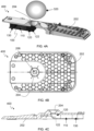
- FIG. 2A illustrates a bottom perspective view of an exemplary acoustic muffler 100 configured in accordance with an embodiment of the subject disclosure attached to a base plate 202 of a food processing device.
- FIGS. 2B and 2C illustrate alternative views of the acoustic muffler 100 shown in FIG. 2A , without the base plate 202 present.
- the acoustic muffler 100 includes a central chamber 110 connected to both an inlet chamber 120 and an outlet chamber 130.
- the inlet chamber 120 may be positioned to receive acoustic energy (i.e., sound or noise) from a motor of the food processing device.
- the inlet chamber 120 may be open to an air cavity surrounding the motor of the food processing device.
- the inlet chamber 120 may be positioned directly beneath, adjacent to, or above the motor of the food processing device to receive air exhausted by the motor and sound generated by the motor.
- the inlet chamber 120 may be fluidly connected to the central chamber 110 and the central chamber 120 may be fluidly connected to the outlet chamber 130 to permit acoustic energy and air and noise to flow from the motor of the food processing device, through the acoustic muffler 100, and into the external environment (i.e., air surrounding the device 10).
- the outlet chamber releases air and acoustic energy into the external environment.
- the outlet chamber may be positioned to release air and acoustic energy from the rear of the food processing device 10 to minimize the noise heard by a user who is located at the front of the device 10.
- the overall direction of sound propagation (D s ) through the acoustic muffler 100 is illustrated in FIG. 2A .
- D s extends from the inlet chamber 120, through the central chamber 110, and then to the outlet chamber 130.
- the cross-sectional area of each chamber is also illustrated in FIG. 2A , with A 1 showing the cross-sectional area of the inlet chamber 120, A 2 showing the cross-sectional area of the central chamber 110, and A 3 showing the cross-sectional area of the outlet chamber 130.
- the cross-sectional areas of the inlet chamber 120, central chamber 110, and outlet chamber 130 are each measured along a plane perpendicular to D s . As shown in FIG.
- the cross-sections of the inlet chamber 120, central chamber 110, and outlet chamber 130 may each be rectangular. However, other configurations are also possible.
- the inlet chamber 120, central chamber 110, and/or outlet chamber 130 may have rectangular, square, trapezoidal, triangular, curved, or round cross-sections.
- the dimensions of the inlet chamber 120, central chamber 110, and outlet chamber 130 may be selected to provide desired acoustic filtering.
- the central chamber 110 may be an expansion chamber and the cross-sectional areas of the inlet chamber 120 (A 1 ) and the outlet chamber 130 (A 3 ) may each be less than the cross-sectional area of the central chamber 110 (A 2 ).
- the central chamber 110 may be a contraction chamber and the cross-sectional areas of the inlet chamber 120 (A 1 ) and the outlet chamber 130 (A 3 ) may each be greater than the cross-sectional area of the central chamber 110 (A 2 ).
- a 2 is greater than A 1 and A 3 .
- a 2 may be at least two, three, four, five, or more times greater than A 1 and A 3 . In other embodiments, A 2 is less than A 1 and A 3 . In some such embodiments, A 2 may be at least two, three, four, five, or more times less than A 1 and A 3 . In various embodiments, A 1 may be equal to or approximately equal to A 3 . However, in other embodiments, A 1 may be unequal to A 3 .
- the difference in cross-sectional area of each adjoining chamber within the acoustic muffler 100 creates a difference in acoustic impedance at each chamber interface.
- the acoustic impedance difference causes some frequencies to be transmitted and others to be reflected back to the source.
- the acoustic muffler can act as a low pass filter, allowing only low frequency sounds through.
- the acoustic muffler 100 can significantly reduce the sound pressure transmitted to the user from the device. Additionally, since the acoustic muffler 100 allows the motor exhaust to exit the device 10, the disclosed acoustic muffler 100 maintains sufficient air flow to the motor, while also reducing noise emitted by the device.
- L i and L o may be 5mm-25mm, 10-20mm, or 10mm-15mm. In some embodiments, L i and L o may be equal or approximately equal. W i and W o may have any measurement discussed herein with respect to L i and L o . In some embodiments, W i is equal to L i and W o is equal to L o . In some embodiments, W c is at least three times greater than or three times less than each of W i and W o . W c may be . 5mm-10mm, 10mm-120mm, 50mm-100mm, or 60mm-80mm. Numerous configurations and variations are possible and contemplated herein.
- the dimensions of the disclosed acoustic muffler 100 can be adjusted to reduce specific frequencies of sound.
- the acoustic muffler 100 may be configured to reduce sound frequencies that are emitted by a particular food processing device.
- the acoustic muffler 100 may be tuned to have a cutoff frequency (i.e., the frequency point where the power transmission coefficient reaches 0.5) at or approximately at 500 Hz, with maximum transmission loss at or approximately at 2300 Hz.
- the acoustic muffler may show a reduction in high frequency acoustic content starting at or approximately at 1000 Hz and/or a sound pressure reduction of at least 2 dB(A), 3 dB(A), 4 dB(A), 5dB(A), or more.
- the length of the central chamber (L c ) may be less than a wavelength of a prominent frequency emitted by the motorized food processing device.
- the back sidewall 122 of the inlet chamber 120 may be curved.
- This configuration may be advantageous for embodiments in which the acoustic muffler 100 is positioned in the lower housing 200 of a device 10 and receives sound energy from above, such as shown in FIG. 1 .
- the acoustic muffler 100 receives sound energy from above, and the curved back sidewall 122 of the inlet chamber 120 directs the sound energy received from above approximately 90° to the overall direction of sound propagation (D s ) through the acoustic muffler 100.
- the acoustic muffler 100 may be positioned to receive sound energy in the same direction as the overall direction of sound propagation (D s ) through the acoustic muffler 100 and, in some such embodiments, the sidewalls of the inlet chamber 120 may each be planar.
- the acoustic muffler 100 shown in FIGS. 2A-2C includes only three chambers: an inlet chamber, 120, central chamber 110, and outlet chamber 130.
- the acoustic muffler may include two or more central chambers, each attached to inlet/outlet chambers having significantly larger or smaller cross-sectional areas than the central chamber to impart acoustic impedance.
- an acoustic muffler having two central chambers is contemplated herein.
- the acoustic muffler includes an inlet chamber connected to a first central chamber that is connected to an outlet chamber connected to a second central chamber that is connected to an outlet chamber, which is exposed to the external environment.
- the acoustic muffler 100 may include internal baffles or other internal structures to direct acoustic energy as desired through the muffler 100.
- the acoustic muffler 100 may be formed of any suitable solid material.
- the acoustic muffler 100 may be formed of a polymeric material, composite, metal, or metal alloy.
- the acoustic muffler 100 may be formed of steel, aluminum, polycarbonate, polyethylene terephthalate (PET), polyethylene terephthalate ethylene (PETE), polyethylene (PE), high-density polyethylene (HDPE), low-density polyethylene (HDPE), polyvinyl chloride (PVC), polypropylene (PP), and/or polystyrene (PS).
- FIGS. 3A and 3B illustrate a base plate 202 for a food processing device 10 configured to couple to an acoustic muffler 100 as presently disclosed.
- FIG. 3A illustrates a top perspective view of the base plate 202
- FIG. 3B illustrates a bottom perspective view of the base plate 202.
- the top surface of the base plate 202 includes a funnel-shaped region 204 with an opening 206 that extends through to the bottom surface of the base plate 202.
- the funnel-shaped region 204 may be positioned to receive air and acoustic energy from a motor of the food processing device and direct the air and acoustic energy into the inlet chamber 120 of an acoustic muffler (not shown).
- the bottom surface of the base plate 202 may include a recessed region 208 sized and configured to receive an acoustic muffler as described herein.
- the acoustic muffler 100 may be coupled to the base plate 202 shown in FIGS. 3A and 3B by placing the muffler 100 on the bottom surface of the base plate 202, with the inlet chamber 120 of the muffler 100 positioned over the opening 206.
- the acoustic muffler 100 may be releasably coupled to the base plate 202 with screws or other fasteners.
- the acoustic muffler 100 may be permanently joined to the base plate 202 by welding, gluing, or other permanent fixation techniques.
- FIGS. 4A-4C illustrate a noise reduction assembly 400 for a food processing device that includes a base plate 202 coupled to an acoustic muffler 100.
- FIG. 4A shows a cross-sectional perspective view of the assembly 400
- FIG. 4B shows a top view of the assembly 400
- FIG. 4C shows another cross-sectional view of the assembly 400.
- the cross-sectional views shown in FIGS. 4A and 4C are taken along the plane marked in FIG. 4B .
- the base plate 202 and acoustic muffler 100 may have any of the features previously described herein.
- the funnel-shaped region 204 of the base plate 202 is positioned directly underneath a motor 320 that exhausts air downwards, such as shown in FIG. 4A .
- the motor 320 generates noise and airflow that both flow into the acoustic muffler 100 via the funnel- shaped region 204.
- the funnel-shaped region 204 increases the acoustic energy and air that enters the muffler's central chamber 110.
- the inlet chamber 120 includes a curved back sidewall 122 that diverts downwardly flowing air and acoustic energy 90° to flow through the central chamber 110 and outlet chamber 130 of the muffler 100 along a horizontal path.
- some or all features of the noise reduction assembly 400 may be integrated.
- some or all features of the acoustic muffler 100 may be integrated with the funnel region 204 and/or other features of the base plate 202.
- a noise reduction assembly 400 has an integrally formed acoustic muffler 100 and funnel region 204, which can be coupled to a base plate 202.
- the noise reduction assembly 400 is a single component having all features of the acoustic muffler 100 and the base plate 202, which may be formed, for example, by injection molding or other techniques.
- the acoustic muffler 100 may include one or more resonance chambers.
- a resonance chamber may act as an acoustic filter by reducing noise at a certain frequency.
- FIG. 5A illustrates a schematic diagram of an exemplary resonance chamber 500, namely a Helmholtz resonator structure.
- V is the volume of air in the resonance chamber 500
- S is the cross-sectional area of the neck 502
- L is the length of the neck 502.
- FIG. 5B illustrates a noise reduction assembly 400 having an acoustic muffler 100 with a resonance chamber 500 and baseplate 202.
- FIG. 5C illustrates a cross-sectional view of the noise reduction assembly 400 shown in FIG. 5B .
- the resonance chamber 500 extends from the central chamber 110 and is positioned in parallel with the overall direction of sound propagation through the acoustic muffler 100.
- FIG. 6 illustrates a method of reducing sound emitted by a food processing device (method 600) using any of the devices and techniques disclosed herein.
- method 600 includes operating a motor of the food processing device (602).
- Method 600 continues with directing air exhausted by the motor and noise generated by the motor into a funnel-shaped region leading to an acoustic muffler having an inlet chamber fluidly connected to a central chamber that is fluidly connected to an outlet chamber open to an external environment (604).
- Method 600 continues with directing the air exhasted by the motor and the noise generated by the motor through the acoustic muffler and into the external environment.
- Any food processing device, 10, motor 320, acoustic muffler 100, and/or noise reduction assembly 400 described herein may be used to carry out the elements of method 600.
- the food processing device may be at least one selected from the group of: an ice cream maker, a blender, a mixer, a micro puree machine, and a type of food processing device capable of blending, mixing, pureeing, slicing, dicing, chopping, grating, shaving, peeling, grinding, squeezing, folding, and/or kneading.
- method 600 may reduce the sound emitted by the food processing device by at least 2 dB or at least 4 dB.
- air and noise may exit the acoustic muffler via the outlet chamber at a rear of the food processing device.
- the disclosed acoustic muffler can be tuned to filter out desired sound frequencies. Techniques for adjusting dimensions of the disclosed acoustic muffler to reduce or eliminate particular sound frequencies are described below, along with experimental testing data, and possible methods of use.
- each type of food processing device has a unique frequency content. That is, each motorized device may produce different acoustic energy at different frequencies. Humans are more perceptive to sound frequencies of between 2000 and 5000 Hz. It could be helpful for the disclosed acoustic muffler to reduce noise in a frequency band produced by the food processing device to which it is coupled without reducing air flow around the motor.
- Acoustic impedance is the opposition or resistance to acoustic flow which results from an acoustic pressure difference.
- Acoustic impedance is a frequency dependent variable and will have different values at different frequencies. So, the acoustic impedance of a component at 100 Hz may not be the same as the acoustic impedance of the same component at 500 Hz.
- the acoustic impedance of the main duct i.e., the inlet and outlet chambers
- central chamber i.e., the central chamber
- the magnitude of acoustic particle velocity of a plane wave is equivalent to the magnitude of acoustic pressure divided by the product of the speed of sound ( c ) and air density ( ⁇ ).
- the frequency content of a food processing device was measured.
- the food processing device used for this example was an NC 100 unit, commercially known as the "Ninja TM CREAMi ® 7-in-1 Ice Cream Maker".
- the measured frequency content of this device is shown in FIG. 8 .
- Frequency content was measured in 1/3 rd octave bands, and three runs were conducted. As shown in FIG. 8 , most of the acoustic energy is between 1000 and 4000 Hz (the highest decibel measurements on the graph).
- the kL value is 0.6411 at 1000 Hz and 2.5646 at 4000 Hz. Although this is not much less than 1, the muffler met space constraints for this particular food processing device.
- the resulting power transmission coefficient showed its first "valley" of high noise reduction between 1000 and 4000 Hz. This is an area where the NC100 device had the most noise and where humans are very sensitive to hearing.
- the value of the power transmission coefficient in this valley can be raised up or down depending on the ratio of the areas of the central chamber to the inlet/outlet. The larger the ratio of this area, the more noise reduction will result.
- the "cutoff frequency” defines the performance of filters of these types and is defined as the frequency point where the power transmission coefficient reaches 0.5. This is also called the “half power point” or the “3 dB down point,”, that is when transmission loss will reach 3 dB.
- the power transmission coefficient and transmission loss of this tuned design is shown in FIG. 9 .
- This frequency range of at least 3 dB noise reduction falls in the desired range of 1000 and 4000 Hz, showing that this muffler has been tuned specifically for the NC100 product.
- a food processing device (NC100) was subjected to acoustic and temperature testing.
- the device was tested both with and without an acoustic muffler configured in accordance with the present disclosure.
- the acoustic muffler had an inlet chamber having a cross-section of 12mm x 12mm, an outlet chamber having a cross-section of 12mm x 12 mm, and a central expansion chamber having a cross-section of 12mm x 79mm and a length of 35mm.
- Acoustics of the device were measured by three microphones, each placed 1 meter from the device in an anechoic chamber. The energy average taken from each of the three microphones was calculated. Three runs of each test (for the device with and without the muffler) were performed.
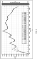
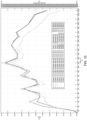
- FIG. 10 illustrates the measured averaged sound pressure level of the device (with and without the acoustic muffler) over three runs in 1/3 rd octave bands. As shown in FIG. 10 , significant noise reduction began near 1250 Hz and upwards. The overall sound pressure levels of the three runs were averaged and the results are shown in Table 1 below. Table 1: Sound Pressure for Food Processing Device with and without Acoustic Muffler Device Baseline 76.7 dB(A) sound pressure at 1m Device with Muffler 72.7 dB(A) sound pressure at 1m
- dB(A) units indicate that the measured decibel units (dB) have been "A-weighted” according to standard techniques in the art.
- measured decibel levels are A- weighted, certain frequencies are weighted differently than others to approximate how humans perceive sound at different frequencies. For example, humans hear better at 3000 Hz, so A-weighting techniques artificially boost those frequencies, and artificially diminish frequencies at which humans do not hear well, such as at or around 20 Hz.
- decibel scale is logarithmic.
- the smallest audible sound is 0dB.
- a sound that is 10 dB is ten times more powerful than a sound of 0 dB and a sound that is 30 dB is 1,000 times more powerful than a 0 dB sound.
- a noise reduction of 4 dB (or 4 dB(A)) is therefore significant and non-trivial.
- FIG. 11 illustrates the measured averaged sound pressure level of a food processing device (with and without an acoustic muffler) over three runs in 1/3 rd octave bands. As shown in FIG. 11 , the acoustic muffler caused significant noise reduction near 1250 Hz and upwards.
- a food processing device outfitted with the acoustic muffler described in Example 2 was subjected to heat testing.
- the heat testing was conducted in accordance with generally accepted industry practices and confirmed that the disclosed acoustic muffler allowed sufficient air flow to cool the motor of the device.
- This application includes the following implementations:
Landscapes
- Engineering & Computer Science (AREA)
- Physics & Mathematics (AREA)
- Acoustics & Sound (AREA)
- Multimedia (AREA)
- Combustion & Propulsion (AREA)
- Chemical & Material Sciences (AREA)
- Aviation & Aerospace Engineering (AREA)
- Fluid Mechanics (AREA)
- Mechanical Engineering (AREA)
- Food Science & Technology (AREA)
- Power Engineering (AREA)
- General Engineering & Computer Science (AREA)
- Food-Manufacturing Devices (AREA)
- Exhaust Silencers (AREA)
Abstract
Description
- The present disclosure relates to an acoustic muffler for a motorized food processing device and, more particularly, to an acoustic muffler having a central expansion or contraction chamber to attenuate sound within a certain frequency range.
- Home appliances with electric motors, such as, for example, blenders, ice cream makers, and stand mixers can be very loud. A common method of noise reduction is to surround portions of the appliance with foam. However, foam restricts air flow and makes it harder to cool the motor. Another approach is to seal the motor off from the outside environment. This approach creates similar complications since there is no external airflow available to cool the motor. Some blenders and other similar devices are partially sealed and include an exhaust/intake vent that allows external air to flow into the motor and then exit the device. This can provide sufficient air flow for the device's motor, but results in significant noise being released into the environment. A solution is needed to reduce undesirable noise emitted by food processing devices without compromising air flow to and from the motor.
- The disclosure describes an acoustic muffler for a motorized food processing device. In some embodiments, the acoustic muffler includes a central chamber having an attached inlet chamber and outlet chamber. By adjusting the dimensions of the chambers, specifically the relative cross-sectional areas of the inlet chamber, central chamber, and outlet chamber, the acoustic muffler can be tuned to reduce noise emitted by the food processing device in a specific frequency range. Additionally, since the presently disclosed acoustic muffler permits external air to flow freely to and from the device's motor, cooling of the motor is not significantly impacted. Embodiments of the acoustic muffler, food processing devices that include the acoustic muffler, and related methods of use of the disclosed devices may include one or more of the following, in any suitable combination.
- Embodiments of an acoustic muffler for a motorized food processing device as disclosed herein include an acoustic muffler with an inlet chamber, a central chamber in fluid communication with the inlet chamber, and an outlet chamber in fluid communication with the central chamber and an external environment. The inlet chamber has a first cross-sectional area (A1), the central chamber has a second cross-sectional area (A2), and the outlet chamber has a third cross-sectional area (A3). A2 is either greater than or less than each of A1 and A3. A2 may be at least three times greater than each of A1 and A3 or three times less than each of A1 and A3. In embodiments in which A2 is at least three times greater than each of A1 and A3, the central chamber is an expansion chamber. In embodiments in which A2 is at least three times less than each of A1 and A3, the central chamber is a contraction chamber. A1, A2, and A3 are measured along a plane perpendicular to a direction of sound propagation (Ds) through the acoustic muffler.
- In some embodiments, the motorized food processing device is at least one selected from the group of: an ice cream maker, a blender, a mixer, a micro puree machine, and a type of food processing device capable of blending, mixing, pureeing, slicing, dicing, chopping, grating, shaving, peeling, grinding, squeezing, folding, and/or kneading. The outlet chamber may be open to air surrounding the motorized food processing device and the inlet chamber may be in fluid communication with air expelled from a motor of the motorized food processing device. In these and other embodiments, the acoustic muffler reduces sound pressure emitted by the motorized food processing device by at least 2 dB. In select embodiments, the acoustic muffler has a cutoff frequency at approximately 500 Hz, with a maximum transmission loss at approximately at 2300 Hz. The acoustic muffler may also include a funnel-shaped region positioned to receive air exhausted from the motor and direct the air to the inlet chamber. In some embodiments, the central chamber has a length measured along a direction of sound propagation (Ds) through the acoustic muffler, and the length is less than a wavelength of a prominent frequency emitted by the motorized food processing device. In select embodiments, the outlet chamber may be directed toward a rear of the motorized food processing device.
- In another aspect, methods of reducing sound emitted by a food processing device are also disclosed. These methods may include operating a motor of the food processing device, directing air exhausted by the motor and noise generated by the motor into a funnel-shaped region leading to an acoustic muffler having an inlet chamber fluidly connected to a central chamber that is fluidly connected to an outlet chamber open to an external environment, and directing the air exhasted by the motor and the noise generated by the motor through the acoustic muffler and into the external environment.
- In some embodiments, the inlet chamber has a first cross-sectional area (A1), the central chamber has a second cross-sectional area (A2), and the outlet chamber has a third cross- sectional area (A3). A1, A2, and A3 are each measured along a plane perpendicular to a direction of sound propagation (Ds) through the acoustic muffler, and A2 is at least three times greater than each of A1 and A3 or three times less than each of A1 and A3. The food processing device may be at least one selected from the group of: an ice cream maker, a blender, a mixer, a micro puree machine, and a type of food processing device capable of blending, mixing, pureeing, slicing, dicing, chopping, grating, shaving, peeling, grinding, squeezing, folding, and/or kneading. In some embodiments, the acousic muffler reduces the sound emitted by the food processing device by at least 2 dB or by at least 4 dB. If desired, the air exhausted by the motor and the noise generated by the motor may exit the acoustic muffler via the outlet chamber positioned in the rear of the food processing device.
- In yet another aspect, a food processing device having reduced noise output is disclosed. The food processing device includes a housing containing a motor with an air intake and an air exhaust and a noise reduction assembly. The noise reduction assembly includes an acoustic muffler with an inlet chamber, an outlet chamber, and a central chamber in fluid connection with both the inlet chamber and the outlet chamber. The outlet chamber is open to air surrounding the housing. The noise reduction assembly also includes a funnel-shaped region positioned proximate to the air exhaust from the motor and entends to the inlet chamber. The inlet chamber has a first cross-sectional area (A1), the central chamber has a second cross-sectional area (A2), and the outlet chamber has a third cross-sectional area (A3), each measured along a plane perpendicular to a direction of sound propagation (Ds) through the acoustic muffler. A2 is at least three times greater than each of A1 and A3 or three times less than each of A1 and A3. In some embodiments, the noise reduction assembly reduces a noise output of the food processing device by at least 2 dB.
- A reading of the following detailed description and a review of the associated drawings will make apparent the advantages of these and other structures. Both the foregoing general description and the following detailed description serve as an explanation only and do not restrict aspects of the disclosure as claimed.
- Reference to the detailed description, combined with the following figures, will make the disclosure more fully understood, wherein:
-
FIG. 1 shows a food processing device outfitted with an acoustic muffler in accordance with some embodiments of this disclosure; -
FIG. 2A shows a bottom perspective view of the food processing device and acoustic muffler ofFIG. 1 , according to some embodiments; -
FIGS. 2B and 2C illustrate the acoustic muffler ofFIG. 2A , shown without the food processing device, according to some embodiments; -
FIGS. 3A and 3B illustrate a base plate for a food processing device configured to couple to an acoustic muffler, according to some embodiments; -
FIGS. 4A-4C illustrate a noise reduction assembly for a food processing device, according to some embodiments; -
FIG. 5A illustrates a schematic diagram of a resonance chamber that may be used in connection with the disclosed acoustic muffler, according to some embodiments; -
FIGS. 5B and 5C illustrate a noise reduction assembly having an acoustic muffler with a resonance chamber, according to some embodiments; -
FIG. 6 illustrates a method of using a food processing device outfitted with an acoustic muffler, according to some embodiments; -
FIG. 7 illustrates a graph of calculated power transmission coefficient values for various frequencies of an example of an acoustic muffler configured in accordance with some embodiments; -
FIG. 8 illustrates a graph of measured frequency content for an example of a food processing device without an acoustic muffler as disclosed herein; -
FIG. 9 illustrates a graph of calculated power transmission coefficient and transmission loss of an example of an acoustic muffler, according to some embodiments; -
FIG. 10 illustrates a graph of measured averaged sound pressure level of a food processing device, with and without an acoustic muffler, according to some embodiments; and -
FIG. 11 illustrates a graph of measured averaged sound pressure level of a food processing device, with and without an acoustic muffler, according to some embodiments. - In the following description, like components have the same reference numerals, regardless of different illustrated embodiments. To illustrate embodiments clearly and concisely, the drawings may not necessarily reflect appropriate scale and may have certain structures shown in somewhat schematic form. The disclosure may describe and/or illustrate structures in one embodiment, and in the same way or in a similar way in one or more other embodiments, and/or combined with or instead of the structures of the other embodiments.
- In the specification and claims, for the purposes of describing and defining the invention, the terms "about" and "substantially" represent the inherent degree of uncertainty attributed to any quantitative comparison, value, measurement, or other representation. The terms "about" and "substantially" moreover represent the degree by which a quantitative representation may vary from a stated reference without resulting in a change in the basic function of the subject matter at issue. Open-ended terms, such as "comprise," "include," and/or plural forms of each, include the listed parts and can include additional parts not listed, while terms such as "and/or" include one or more of the listed parts and combinations of the listed parts. Use of the terms "top," "bottom," "above," "below" and the like helps only in the clear description of the disclosure and does not limit the structure, positioning and/or operation of the acoustic muffler in any manner.
- An acoustic muffler for a motorized food processing device is disclosed, along with related devices, noise reduction assemblies, and methods.
FIG. 1 shows a perspective view of an exemplaryfood processing device 10 having anacoustic muffler 100 configured in accordance with an embodiment of the present disclosure. Thefood processing device 10 may be any type of motorized food processing device, such as a blender, ice cream maker, mixer, micro puree machine, or other type of food processing device capable of blending, mixing, pureeing, slicing, dicing, chopping, grating, shaving, peeling, grinding, squeezing, folding, kneading, or any suitable combination of the foregoing. - As shown in
FIG. 1 , thefood processing device 10 includes alower housing 200 attached to anupper housing 300. If desired, a middle housing may extend between thelower housing 200 and the upper housing. Theupper housing 300 may include an interface for receiving user inputs to control thefood processing device 10 and/or display information. Thefood processing device 10 may also include a removable container and/or lid. A user may couple the container to a coupling on a surface of the upper housing 300 (e.g., by rotating the container relative to the coupling). When engaged with the coupling, the container may or may not be aligned with a vertical axis of thefood processing device 10. In embodiments in which the container is not aligned with a vertical axis of thefood processing device 10 when the container is engaged with the coupling, the container may form an angle of between 1 degree and 180 degrees (such about 45 degrees to about 55 degrees) relative to the vertical axis. - The
food processing device 10 includes a motor to drive components within thedevice 10 to perform the intended food processing function(s). Various types of motors for food processing devices are known in the relevant art and the disclosedacoustic mufflers 100 can be used in connection with food processing devices having any type of known AC or DC motor.
The motor may be positioned within thelower housing 200 or theupper housing 300 ofdevice 10, as desired. - The
acoustic muffler 100 is positioned proximate to the motor of thefood processing device 10. For example, as shown inFIG. 1 , theacoustic muffler 100 may be positioned within thelower housing 200. However, in other embodiments, theacoustic muffler 100 may be positioned in theupper housing 300 or in another location, depending on where the device's motor resides. In some embodiments, such as thefood processing device 10 shown inFIG. 1 , thelower housing 200 may include abase plate 202 to which theacoustic muffler 100 may be attached. Theacoustic muffler 100 may be attachable to and/or removable from the base plate
202. However, in other embodiments, thebase plate 202 and theacoustic muffler 100 may be fixedly joined together or may be integrally formed as a single component. Numerous configurations are possible and contemplated herein -
FIG. 2A illustrates a bottom perspective view of an exemplaryacoustic muffler 100 configured in accordance with an embodiment of the subject disclosure attached to abase plate 202 of a food processing device.FIGS. 2B and 2C illustrate alternative views of theacoustic muffler 100 shown inFIG. 2A , without thebase plate 202 present. Theacoustic muffler 100 includes acentral chamber 110 connected to both aninlet chamber 120 and anoutlet chamber 130. - The
inlet chamber 120 may be positioned to receive acoustic energy (i.e., sound or noise) from a motor of the food processing device. In some embodiments, theinlet chamber 120 may be open to an air cavity surrounding the motor of the food processing device. In these and other embodiments, theinlet chamber 120 may be positioned directly beneath, adjacent to, or above the motor of the food processing device to receive air exhausted by the motor and sound generated by the motor. Theinlet chamber 120 may be fluidly connected to thecentral chamber 110 and thecentral chamber 120 may be fluidly connected to theoutlet chamber 130 to permit acoustic energy and air and noise to flow from the motor of the food processing device, through theacoustic muffler 100, and into the external environment (i.e., air surrounding the device 10). The outlet chamber releases air and acoustic energy into the external environment. The outlet chamber may be positioned to release air and acoustic energy from the rear of thefood processing device 10 to minimize the noise heard by a user who is located at the front of thedevice 10. - The overall direction of sound propagation (Ds) through the
acoustic muffler 100 is illustrated inFIG. 2A . As shown inFIG. 2A , Ds extends from theinlet chamber 120, through thecentral chamber 110, and then to theoutlet chamber 130. The cross-sectional area of each chamber is also illustrated inFIG. 2A , with A1 showing the cross-sectional area of theinlet chamber 120, A2 showing the cross-sectional area of thecentral chamber 110, and A3 showing the cross-sectional area of theoutlet chamber 130. The cross-sectional areas of theinlet chamber 120,central chamber 110, andoutlet chamber 130 are each measured along a plane perpendicular to Ds. As shown inFIG. 2A , the cross-sections of theinlet chamber 120,central chamber 110, andoutlet chamber 130 may each be rectangular. However, other configurations are also possible. For example, in some embodiments, theinlet chamber 120,central chamber 110, and/oroutlet chamber 130 may have rectangular, square, trapezoidal, triangular, curved, or round cross-sections. - As discussed in more detail below, the dimensions of the
inlet chamber 120,central chamber 110, andoutlet chamber 130 may be selected to provide desired acoustic filtering. For example, in some embodiments, thecentral chamber 110 may be an expansion chamber and the cross-sectional areas of the inlet chamber 120 (A1) and the outlet chamber 130 (A3) may each be less than the cross-sectional area of the central chamber 110 (A2). However, in other embodiments, thecentral chamber 110 may be a contraction chamber and the cross-sectional areas of the inlet chamber 120 (A1) and the outlet chamber 130 (A3) may each be greater than the cross-sectional area of the central chamber 110 (A2). Thus, in select embodiments, A2 is greater than A1 and A3. In some such embodiments, A2 may be at least two, three, four, five, or more times greater than A1 and A3. In other embodiments, A2 is less than A1 and A3. In some such embodiments, A2 may be at least two, three, four, five, or more times less than A1 and A3. In various embodiments, A1 may be equal to or approximately equal to A3. However, in other embodiments, A1 may be unequal to A3. - The difference in cross-sectional area of each adjoining chamber within the
acoustic muffler 100 creates a difference in acoustic impedance at each chamber interface. The acoustic impedance difference causes some frequencies to be transmitted and others to be reflected back to the source. If desired, the acoustic muffler can act as a low pass filter, allowing only low frequency sounds through. When attached to an air exhaust of a motor for a food processing device, theacoustic muffler 100 can significantly reduce the sound pressure transmitted to the user from the device. Additionally, since theacoustic muffler 100 allows the motor exhaust to exit thedevice 10, the disclosedacoustic muffler 100 maintains sufficient air flow to the motor, while also reducing noise emitted by the device. -
FIGS. 2B and 2C illustrate the acoustic muffler ofFIG. 2A withoutbase plate 202.FIG. 2B shows a bottom perspective view of theacoustic muffler 100 andFIG. 2C shows a top perspective view of theacoustic muffler 100. As can be seen fromFIGS. 2A-2C , thebase plate 202 forms a top surface of theacoustic muffler 100 and also forms sides of thecentral chamber 110, effectively sealing in theinlet chamber 120 andcentral chamber 110 from the external environment, while leaving theoutlet chamber 130 exposed to the external environment. In other embodiments, however, theacoustic muffler 100 may include a top surface that is distinct from thebase plate 202. In some such embodiments, theacoustic muffler 100 may also include sidewalls for thecentral chamber 110 that are distinct from features of thebase plate 202. - The
acoustic muffler 100 may have any desired dimensions. As shown inFIGS. 2B and
2C, theinlet chamber 120 may have a length (Li), width (Wi), and height (Hi), the outlet chamber may have a length (Lo), width (Wo), and height (Ho), and the central chamber may have a length (Lc), width (Wc), and height (Hc). In some embodiments, Hi, Ho, and Hc may be equal or approximately equal. In these and other embodiments, Hi, Ho, and/or Hc may be 5mm-25mm, 10mm-20mm, or 10mm-15mm. In these and other embodiments, Li and Lo may be 5mm-25mm, 10-20mm, or 10mm-15mm. In some embodiments, Li and Lo may be equal or approximately equal. Wi and Wo may have any measurement discussed herein with respect to Li and Lo. In some embodiments, Wi is equal to Li and Wo is equal to Lo. In some embodiments, Wc is at least three times greater than or three times less than each of Wi and Wo. Wc may be . 5mm-10mm, 10mm-120mm, 50mm-100mm, or 60mm-80mm. Numerous configurations and variations are possible and contemplated herein. - As described in more detail below, the dimensions of the disclosed
acoustic muffler 100 can be adjusted to reduce specific frequencies of sound. For example, theacoustic muffler 100 may be configured to reduce sound frequencies that are emitted by a particular food processing device. In select embodiments, theacoustic muffler 100 may be tuned to have a cutoff frequency (i.e., the frequency point where the power transmission coefficient reaches 0.5) at or approximately at 500 Hz, with maximum transmission loss at or approximately at 2300 Hz. In select embodiments, the acoustic muffler may show a reduction in high frequency acoustic content starting at or approximately at 1000 Hz and/or a sound pressure reduction of at least 2 dB(A), 3 dB(A), 4 dB(A), 5dB(A), or more. In these and other embodiments, the length of the central chamber (Lc) may be less than a wavelength of a prominent frequency emitted by the motorized food processing device. - As shown in
FIGS. 2A-2C , theback sidewall 122 of theinlet chamber 120 may be curved. This configuration may be advantageous for embodiments in which theacoustic muffler 100 is positioned in thelower housing 200 of adevice 10 and receives sound energy from above, such as shown inFIG. 1 . In some such embodiments, theacoustic muffler 100 receives sound energy from above, and thecurved back sidewall 122 of theinlet chamber 120 directs the sound energy received from above approximately 90° to the overall direction of sound propagation (Ds) through theacoustic muffler 100. However, in other embodiments theacoustic muffler 100 may be positioned to receive sound energy in the same direction as the overall direction of sound propagation (Ds) through theacoustic muffler 100 and, in some such embodiments, the sidewalls of theinlet chamber 120 may each be planar. - The
acoustic muffler 100 shown inFIGS. 2A-2C includes only three chambers: an inlet chamber, 120,central chamber 110, andoutlet chamber 130. In other embodiments, however, the acoustic muffler may include two or more central chambers, each attached to inlet/outlet chambers having significantly larger or smaller cross-sectional areas than the central chamber to impart acoustic impedance. For example, an acoustic muffler having two central chambers is contemplated herein. In such embodiments, the acoustic muffler includes an inlet chamber connected to a first central chamber that is connected to an outlet chamber connected to a second central chamber that is connected to an outlet chamber, which is exposed to the external environment. Other embodiments are also contemplated herein. For example, theacoustic muffler 100 may include internal baffles or other internal structures to direct acoustic energy as desired through themuffler 100. - The
acoustic muffler 100 may be formed of any suitable solid material. In some embodiments, theacoustic muffler 100 may be formed of a polymeric material, composite, metal, or metal alloy. In select embodiments, theacoustic muffler 100 may be formed of steel, aluminum, polycarbonate, polyethylene terephthalate (PET), polyethylene terephthalate ethylene (PETE), polyethylene (PE), high-density polyethylene (HDPE), low-density polyethylene (HDPE), polyvinyl chloride (PVC), polypropylene (PP), and/or polystyrene (PS). -
FIGS. 3A and 3B illustrate abase plate 202 for afood processing device 10 configured to couple to anacoustic muffler 100 as presently disclosed.FIG. 3A illustrates a top perspective view of thebase plate 202 andFIG. 3B illustrates a bottom perspective view of the base plate
202. As shown inFIG. 3A , the top surface of thebase plate 202 includes a funnel-shapedregion 204 with anopening 206 that extends through to the bottom surface of thebase plate 202. The funnel-shapedregion 204 may be positioned to receive air and acoustic energy from a motor of the food processing device and direct the air and acoustic energy into theinlet chamber 120 of an acoustic muffler (not shown). As shown inFIG. 3B , the bottom surface of thebase plate 202 may include a recessedregion 208 sized and configured to receive an acoustic muffler as described herein. - The
acoustic muffler 100 may be coupled to thebase plate 202 shown inFIGS. 3A and 3B by placing themuffler 100 on the bottom surface of thebase plate 202, with theinlet chamber 120 of themuffler 100 positioned over theopening 206. Theacoustic muffler 100 may be releasably coupled to thebase plate 202 with screws or other fasteners. However, in other embodiments, theacoustic muffler 100 may be permanently joined to thebase plate 202 by welding, gluing, or other permanent fixation techniques. -
FIGS. 4A-4C illustrate anoise reduction assembly 400 for a food processing device that includes abase plate 202 coupled to anacoustic muffler 100.FIG. 4A shows a cross-sectional perspective view of theassembly 400,FIG. 4B shows a top view of theassembly 400, andFIG. 4C shows another cross-sectional view of theassembly 400. The cross-sectional views shown inFIGS. 4A and 4C are taken along the plane marked inFIG. 4B . Thebase plate 202 andacoustic muffler 100 may have any of the features previously described herein. In some embodiments, the funnel-shapedregion 204 of thebase plate 202 is positioned directly underneath amotor 320 that exhausts air downwards, such as shown inFIG. 4A . In some such embodiments, themotor 320 generates noise and airflow that both flow into theacoustic muffler 100 via the funnel- shapedregion 204. The funnel-shapedregion 204 increases the acoustic energy and air that enters the muffler'scentral chamber 110. Theinlet chamber 120 includes acurved back sidewall 122 that diverts downwardly flowing air and acoustic energy 90° to flow through thecentral chamber 110 andoutlet chamber 130 of themuffler 100 along a horizontal path. - In some embodiments, some or all features of the
noise reduction assembly 400 may be integrated. For example, some or all features of theacoustic muffler 100 may be integrated with thefunnel region 204 and/or other features of thebase plate 202. In select embodiments, anoise reduction assembly 400 has an integrally formedacoustic muffler 100 and funnelregion 204, which can be coupled to abase plate 202. In other embodiments, thenoise reduction assembly 400 is a single component having all features of theacoustic muffler 100 and thebase plate 202, which may be formed, for example, by injection molding or other techniques. - If desired, the
acoustic muffler 100 may include one or more resonance chambers. A resonance chamber may act as an acoustic filter by reducing noise at a certain frequency.FIG. 5A illustrates a schematic diagram of anexemplary resonance chamber 500, namely a Helmholtz resonator structure. InFIG. 5A , "V" is the volume of air in theresonance chamber 500, "S" is the cross-sectional area of theneck 502, and "L" is the length of theneck 502.FIG. 5B illustrates anoise reduction assembly 400 having anacoustic muffler 100 with aresonance chamber 500 andbaseplate 202.FIG. 5C illustrates a cross-sectional view of thenoise reduction assembly 400 shown inFIG. 5B . As shown inFIG. 5C , theresonance chamber 500 extends from thecentral chamber 110 and is positioned in parallel with the overall direction of sound propagation through theacoustic muffler 100. -
FIG. 6 illustrates a method of reducing sound emitted by a food processing device (method 600) using any of the devices and techniques disclosed herein. As shown inFIG. 6 ,method 600 includes operating a motor of the food processing device (602).Method 600 continues with directing air exhausted by the motor and noise generated by the motor into a funnel-shaped region leading to an acoustic muffler having an inlet chamber fluidly connected to a central chamber that is fluidly connected to an outlet chamber open to an external environment (604).Method 600 continues with directing the air exhasted by the motor and the noise generated by the motor through the acoustic muffler and into the external environment. Any food processing device, 10,motor 320,acoustic muffler 100, and/ornoise reduction assembly 400 described herein may be used to carry out the elements ofmethod 600. - In
method 600, the food processing device may be at least one selected from the group of: an ice cream maker, a blender, a mixer, a micro puree machine, and a type of food processing device capable of blending, mixing, pureeing, slicing, dicing, chopping, grating, shaving, peeling, grinding, squeezing, folding, and/or kneading. In these and other embodiments,method 600 may reduce the sound emitted by the food processing device by at least 2 dB or at least 4 dB. In select embodiments, air and noise may exit the acoustic muffler via the outlet chamber at a rear of the food processing device. - While the disclosure particularly shows and describes preferred embodiments, those skilled in the art will understand that various changes in form and details may exist without departing from the spirit and scope of the present application as defined by the appended claims. The scope of this present application intends to cover such variations. As such, the foregoing description of embodiments of the present application does not intend to limit the full scope conveyed by the appended claims.
- Although some particular embodiments of the disclosed acoustic muffler have already been described in detail, additional and alternative embodiments of the acoustic muffler are also possible. Specifically, the disclosed acoustic muffler can be tuned to filter out desired sound frequencies. Techniques for adjusting dimensions of the disclosed acoustic muffler to reduce or eliminate particular sound frequencies are described below, along with experimental testing data, and possible methods of use.
- As previously mentioned, food processing devices can create undesirable noise. Additionally, each type of food processing device has a unique frequency content. That is, each motorized device may produce different acoustic energy at different frequencies. Humans are more perceptive to sound frequencies of between 2000 and 5000 Hz. It could be helpful for the disclosed acoustic muffler to reduce noise in a frequency band produced by the food processing device to which it is coupled without reducing air flow around the motor.
- Acoustic impedance is the opposition or resistance to acoustic flow which results from an acoustic pressure difference. In the disclosed muffler, acoustic impedance is the ratio of potential (pressure, P) to flow (volume velocity, U). Therefore, acoustic impedance can be expressed with Equation 1:

- Acoustic impedance is a frequency dependent variable and will have different values at different frequencies. So, the acoustic impedance of a component at 100 Hz may not be the same as the acoustic impedance of the same component at 500 Hz. To analyze how the disclosed acoustic muffler behaves, the acoustic impedance of the main duct (i.e., the inlet and outlet chambers) and central chamber should be considered.
- The magnitude of acoustic particle velocity of a plane wave is equivalent to the magnitude of acoustic pressure divided by the product of the speed of sound (c) and air density (ρ). The acoustic impedance for a simple duct of cross-sectional area S can then be calculated, knowing that the volume velocity U is the product of particle velocity (u) and cross-sectional area. This is shown in Equation 2:

- While the density and speed of sound in each of the three chambers can be assumed constant, the cross-sectional area changes. Since the area of the central expansion chamber is larger than that of the inlet and outlet chambers, the acoustic impedances are different. This leaves 2 boundaries where the impedance of the medium must change. At each of these boundaries, conservation of mass, momentum, and frequency must be maintained. By applying these boundary conditions at the inlet and exit of the central (e.g., expansion) chamber, one can derive an expression for the pressure transmission coefficient, T, through the duct/chamber.
Knowing that Z1 (acoustic impedance of the inlet) and Z3 (acoustic impedance of the exit) are equal,Equation 3 results:
- In this equation, k2 is the wavenumber (ratio of angular frequency in the central expansion chamber to the speed of sound), L is the length of the expansion chamber, and j is the square root of -1. This will reveal how much of the acoustic pressure entering the duct is transmitted. For example, if the incident pressure is 10 Pa and the pressure transmission coefficient is 0.1, the transmitted pressure will only be 1 Pa. It is often more beneficial to look at the acoustic power transmission coefficient, which is the same idea, but tells how much acoustic power is transmitted through the duct/chamber. Because Tis a complex number and Z1=Z3, the power transmission coefficient is just the pressure transmission coefficient multiplied by its complex conjugate. This is shown in Equation 4:

- Since this is a function of the wavenumber, the power transmission through the central expansion chamber is a function of frequency, and this explains why changes in cross-sectional area affect different frequencies differently. It should also be noted that since S2/
S 1 is added toS 1/S2, it does not matter whether or not S2 is larger thanS 1 or vice versa. The same acoustic performance will result when there is a central "contraction" chamber instead of an expansion chamber. When kL approaches 0, small angle approximations can be used, so cos(kL) is approximately 1 and sin(kL) is approximately 0. This makes the power transmission coefficient at very low frequencies extremely close to 1, indicating that all the energy of low frequency noise is passed through the acoustic muffler. A graph of the power transmission coefficient versus frequency for the dimensions of an exemplary acoustic muffler is shown inFIG. 7 . - At lower frequencies, this has the effect of an acoustic low-pass filter. That is, the power transmission coefficient is close to 1 at low frequencies, so it "passes" low frequencies through. As the frequency gets higher, a much lower ratio of incident power is transmitted through. For this reason, this embodiment is good at attenuating high frequencies to an extent.
- The frequency content of a food processing device (without a muffler) was measured. The food processing device used for this example was an
NC 100 unit, commercially known as the "Ninja™ CREAMi® 7-in-1 Ice Cream Maker". The measured frequency content of this device is shown inFIG. 8 . Frequency content was measured in 1/3rd octave bands, and three runs were conducted. As shown inFIG. 8 , most of the acoustic energy is between 1000 and 4000 Hz (the highest decibel measurements on the graph). - Since most of the measured acoustic energy for this device was between 1000 and 4000 Hz, it would be beneficial to tune the length of the expansion chamber so that kL is less than 1. The kL value for the length of the central expansion chamber at 1000 Hz can be calculated using Equation 5:

- For this embodiment, the kL value is 0.6411 at 1000 Hz and 2.5646 at 4000 Hz. Although this is not much less than 1, the muffler met space constraints for this particular food processing device. The resulting power transmission coefficient showed its first "valley" of high noise reduction between 1000 and 4000 Hz. This is an area where the NC100 device had the most noise and where humans are very sensitive to hearing. The value of the power transmission coefficient in this valley can be raised up or down depending on the ratio of the areas of the central chamber to the inlet/outlet. The larger the ratio of this area, the more noise reduction will result.
- Using the power transmission coefficient, the transmission loss can also be calculated, which gives us the noise reduction in dB through the central chamber, shown in Equation 6:

- The "cutoff frequency" defines the performance of filters of these types and is defined as the frequency point where the power transmission coefficient reaches 0.5. This is also called the "half power point" or the "3 dB down point,", that is when transmission loss will reach 3 dB. The power transmission coefficient and transmission loss of this tuned design is shown in
FIG. 9 . - As shown in
FIG. 9 , peak transmission loss of about 10.54 dB occurred at 2456 Hz. This point occurs above kL=1, but could be adjusted to occur below kL=1 if alternative dimensions for the inlet chamber, outlet chamber, and central chamber were selected. The points where TL=3 dB on either side of this main "noise reduction valley" can also be located. These points occur at 492 Hz and 4409 Hz for this embodiment, which gives this particular embodiment good noise reduction within that entire range and a bandwidth of nearly 4000 Hz. This frequency range of at least 3 dB noise reduction falls in the desired range of 1000 and 4000 Hz, showing that this muffler has been tuned specifically for the NC100 product. - A food processing device (NC100) was subjected to acoustic and temperature testing. The device was tested both with and without an acoustic muffler configured in accordance with the present disclosure. The acoustic muffler had an inlet chamber having a cross-section of 12mm x 12mm, an outlet chamber having a cross-section of 12mm x 12 mm, and a central expansion chamber having a cross-section of 12mm x 79mm and a length of 35mm. Acoustics of the device were measured by three microphones, each placed 1 meter from the device in an anechoic chamber. The energy average taken from each of the three microphones was calculated. Three runs of each test (for the device with and without the muffler) were performed.
-
FIG. 10 illustrates the measured averaged sound pressure level of the device (with and without the acoustic muffler) over three runs in 1/3rd octave bands. As shown inFIG. 10 , significant noise reduction began near 1250 Hz and upwards. The overall sound pressure levels of the three runs were averaged and the results are shown in Table 1 below.Table 1: Sound Pressure for Food Processing Device with and without Acoustic Muffler Device Baseline 76.7 dB(A) sound pressure at 1m Device with Muffler 72.7 dB(A) sound pressure at 1m - As shown in Table 1, the acoustic muffler reduced the overall noise of the device by 4 dB(A). As used herein, "dB(A)" units indicate that the measured decibel units (dB) have been "A-weighted" according to standard techniques in the art. When measured decibel levels are A- weighted, certain frequencies are weighted differently than others to approximate how humans perceive sound at different frequencies. For example, humans hear better at 3000 Hz, so A-weighting techniques artificially boost those frequencies, and artificially diminish frequencies at which humans do not hear well, such as at or around 20 Hz.
- It is important to note that the decibel scale is logarithmic. The smallest audible sound is 0dB. A sound that is 10 dB is ten times more powerful than a sound of 0 dB and a sound that is 30 dB is 1,000 times more powerful than a 0 dB sound. A noise reduction of 4 dB (or 4 dB(A)) is therefore significant and non-trivial.
-
FIG. 11 illustrates the measured averaged sound pressure level of a food processing device (with and without an acoustic muffler) over three runs in 1/3rd octave bands. As shown inFIG. 11 , the acoustic muffler caused significant noise reduction near 1250 Hz and upwards. - A food processing device outfitted with the acoustic muffler described in Example 2 was subjected to heat testing. The heat testing was conducted in accordance with generally accepted industry practices and confirmed that the disclosed acoustic muffler allowed sufficient air flow to cool the motor of the device.
- This application includes the following implementations:
- 1. An implementation of a food processing device having a reduced noise output, the food processing device comprising:
- a housing comprising a motor with an air intake and an air exhaust;
- and a noise reduction assembly comprising:
- an acoustic muffler comprising an inlet chamber, an outlet chamber, and a central chamber in fluid connection with both the inlet chamber and the outlet chamber, wherein the outlet chamber is open to air surrounding the housing; and
- a funnel-shaped region positioned proximate to the air exhaust from the motor and extending to the inlet chamber,
- wherein the inlet chamber has a first cross-sectional area (A1), the central chamber has a second cross-sectional area (A2), and the outlet chamber has a third cross- sectional area (A3), each measured along a plane perpendicular to a direction of sound propagation (Ds) through the acoustic muffler, and
- wherein the second cross-sectional area (A2) is greater than each of the first cross- sectional area (A1) and the third cross-sectional area (A3) or less than each of the first cross- sectional area (A1) and the third cross-sectional area (A3).
- 2. The food processing device of
implementation 1, wherein the noise reduction assembly reduces a noise output of the food processing device by at least 2 dB. - 3. The food processing device of
implementation 1, wherein the second cross-sectional area (A2) is at least three times greater than each of the first cross-sectional area (A1) and the third cross- sectional area (A3) or three times less than each of the first cross-sectional area (A1) and the third cross-sectional area (A3).
Claims (15)
- An acoustic muffler for a motorized food processing device, the acousic muffler comprising:an inlet chamber having a first cross-sectional area (A1);a central chamber in fluid communication with the inlet chamber, the central chamber having a second cross-sectional area (A2); andan outlet chamber in fluid communication with the central chamber and an external environment, the outlet chamber having a third cross-sectional area (A3),wherein the second cross-sectional area (A2) is greater than each of the first cross- sectional area (A1) and the third cross-sectional area (A3) or less than each of the first cross- sectional area (A1) and the third cross-sectional area (A3).
- The acoustic muffler of claim 1, wherein the central chamber is an expansion chamber and the second cross-sectional area (A2) is at least three times greater than each of the first cross- sectional area (A1) and the third cross-sectional area (A3).
- The acoustic muffler of claim 1, wherein the central chamber is a contraction chamber and the second cross-sectional area (A2) is at least three times less than each of the first cross- sectional area (A1) and the third cross-sectional area (A3).
- The acoustic muffler of claim 1, wherien the first cross-sectional area (A1), the second cross-sectional area (A2), and the third cross-sectional area (A3) are measured along a plane perpendicular to a direction of sound propagation (Ds) through the acoustic muffler.
- The acoustic muffler of claim 1, wherein the external environment is air surrounding the motorized food processing device and the inlet chamber is in fluid communication with air expelled from a motor of the motorized food processing device.
- The acoustic muffler of claim 1, wherein the acoustic muffler has a cutoff frequency at approximately 500 Hz, with a maximum transmission loss at approximately at 2300 Hz.
- The acoustic muffler of claim 1, wherein the acoustic muffler reduces sound pressure emitted by the motorized food processing device by at least 2 dB.
- The acoustic muffler of claim 1, wherein the motorized food processing device is at least one selected from the group of: an ice cream maker, a blender, a mixer, a micro puree machine, and a type of food processing device capable of blending, mixing, pureeing, slicing, dicing, chopping, grating, shaving, peeling, grinding, squeezing, folding, and/or kneading.
- The acoustic muffler of claim 1, further comprising a funnel-shaped region positioned to receive air exhausted from the motor, wherein the funnel-shaped region extends to the inlet chamber.
- The acoustic muffler of claim 1, wherein the central chamber has a length measured along a direction of sound propagation (Ds) through the acoustic muffler, and the length is less than a wavelength of a prominent frequency emitted by the motorized food processing device.
- The acoustic muffler of claim 1, wherein the outlet chamber is directed toward a rear of the motorized food processing device.
- A method of reducing sound emitted by a food processing device, the method comprising:operating a motor of the food processing device;directing air exhausted by the motor and noise generated by the motor into a funnel-shaped region leading to an acoustic muffler having an inlet chamber fluidly connected to a central chamber that is fluidly connected to an outlet chamber open to an external environment; anddirecting the air exhasted by the motor and the noise generated by the motor through the acoustic muffler and into the external environment.
- The method of claim 12, wherein the inlet chamber has a first cross-sectional area (A1), the central chamber has a second cross-sectional area (A2), and the outlet chamber has a third cross-sectional area (A3), each measured along a plane perpendicular to a direction of sound propagation (Ds) through the acoustic muffler, and the second cross-sectional area (A2) is at least three times greater than each of the first cross-sectional area (A1) and the third cross-sectional area (A3) or three times less than each of the first cross-sectional area (A1) and the third cross- sectional area (A3).
- The method of claim 12, wherein the food processing device is at least one selected from the group of: an ice cream maker, a blender, a mixer, a micro puree machine, and a type of food processing device capable of blending, mixing, pureeing, slicing, dicing, chopping, grating, shaving, peeling, grinding, squeezing, folding, and/or kneading.
- The method of claim 12, wherein the acousic muffler reduces the sound emitted by the food processing device by at least 2 dB.
Applications Claiming Priority (1)
| Application Number | Priority Date | Filing Date | Title |
|---|---|---|---|
| US18/103,720 US20240257792A1 (en) | 2023-01-31 | 2023-01-31 | Acoustic muffler for a motorized food processing device |
Publications (1)
| Publication Number | Publication Date |
|---|---|
| EP4410161A1 true EP4410161A1 (en) | 2024-08-07 |
Family
ID=87863359
Family Applications (1)
| Application Number | Title | Priority Date | Filing Date |
|---|---|---|---|
| EP23194088.3A Pending EP4410161A1 (en) | 2023-01-31 | 2023-08-29 | Acoustic muffler for a motorized food processing device |
Country Status (5)
| Country | Link |
|---|---|
| US (1) | US20240257792A1 (en) |
| EP (1) | EP4410161A1 (en) |
| CN (2) | CN221668515U (en) |
| DE (1) | DE202023105632U1 (en) |
| WO (1) | WO2024162990A1 (en) |
Families Citing this family (2)
| Publication number | Priority date | Publication date | Assignee | Title |
|---|---|---|---|---|
| US20260091244A1 (en) | 2024-09-30 | 2026-04-02 | Sharkninja Operating Llc | Therapeutic face mask modes of operation |
| US20260090909A1 (en) | 2024-09-30 | 2026-04-02 | Sharkninja Operating Llc | Face masks with therapeutic cooling |
Citations (8)
| Publication number | Priority date | Publication date | Assignee | Title |
|---|---|---|---|---|
| US6722467B1 (en) * | 2002-08-28 | 2004-04-20 | Brunswick Corporation | Noise attenuator for an air supply system of an internal combustion engine |
| KR100635694B1 (en) * | 2004-10-11 | 2006-10-17 | 엘에스전선 주식회사 | High frequency acoustic silencer |
| CN202636713U (en) * | 2012-05-23 | 2013-01-02 | 李澜 | Turbine exhaust silencer |
| CN204165212U (en) * | 2013-12-18 | 2015-02-18 | 海尔集团公司 | A kind of multisection type full rate section air conditioner muffler |
| CN107906748A (en) * | 2017-12-05 | 2018-04-13 | 江苏威能电气有限公司 | It is a kind of can abundant heat gas electric heater |
| CN207400673U (en) * | 2017-05-27 | 2018-05-25 | 广东美的生活电器制造有限公司 | Noise reduction lid, cup lid component and food cooking machine |
| US20190320849A1 (en) * | 2018-04-20 | 2019-10-24 | Hamilton Beach Brands, Inc. | Blender With Baffle For Reducing Noice |
| CN111053425A (en) * | 2018-10-17 | 2020-04-24 | 广东美的白色家电技术创新中心有限公司 | Main unit and kitchen appliance with same |
Family Cites Families (3)
| Publication number | Priority date | Publication date | Assignee | Title |
|---|---|---|---|---|
| US6069423A (en) * | 1999-04-21 | 2000-05-30 | Vita-Mix Corporation | Motor cooling and sound absorbing system |
| CN209285200U (en) * | 2017-12-05 | 2019-08-23 | 九阳股份有限公司 | A kind of food processor of rapid heat dissipation |
| CN209863470U (en) * | 2019-02-22 | 2019-12-31 | 九阳股份有限公司 | Cooking utensil's silencing device and cooking utensil |
-
2023
- 2023-01-31 US US18/103,720 patent/US20240257792A1/en active Pending
- 2023-08-25 WO PCT/US2023/031135 patent/WO2024162990A1/en not_active Ceased
- 2023-08-29 EP EP23194088.3A patent/EP4410161A1/en active Pending
- 2023-09-27 DE DE202023105632.6U patent/DE202023105632U1/en active Active
- 2023-12-21 CN CN202323505084.8U patent/CN221668515U/en active Active
- 2023-12-21 CN CN202311769205.1A patent/CN118430490A/en active Pending
Patent Citations (8)
| Publication number | Priority date | Publication date | Assignee | Title |
|---|---|---|---|---|
| US6722467B1 (en) * | 2002-08-28 | 2004-04-20 | Brunswick Corporation | Noise attenuator for an air supply system of an internal combustion engine |
| KR100635694B1 (en) * | 2004-10-11 | 2006-10-17 | 엘에스전선 주식회사 | High frequency acoustic silencer |
| CN202636713U (en) * | 2012-05-23 | 2013-01-02 | 李澜 | Turbine exhaust silencer |
| CN204165212U (en) * | 2013-12-18 | 2015-02-18 | 海尔集团公司 | A kind of multisection type full rate section air conditioner muffler |
| CN207400673U (en) * | 2017-05-27 | 2018-05-25 | 广东美的生活电器制造有限公司 | Noise reduction lid, cup lid component and food cooking machine |
| CN107906748A (en) * | 2017-12-05 | 2018-04-13 | 江苏威能电气有限公司 | It is a kind of can abundant heat gas electric heater |
| US20190320849A1 (en) * | 2018-04-20 | 2019-10-24 | Hamilton Beach Brands, Inc. | Blender With Baffle For Reducing Noice |
| CN111053425A (en) * | 2018-10-17 | 2020-04-24 | 广东美的白色家电技术创新中心有限公司 | Main unit and kitchen appliance with same |
Also Published As
| Publication number | Publication date |
|---|---|
| US20240257792A1 (en) | 2024-08-01 |
| CN118430490A (en) | 2024-08-02 |
| DE202023105632U1 (en) | 2023-10-17 |
| CN221668515U (en) | 2024-09-06 |
| WO2024162990A1 (en) | 2024-08-08 |
Similar Documents
| Publication | Publication Date | Title |
|---|---|---|
| US20240257792A1 (en) | Acoustic muffler for a motorized food processing device | |
| JP6219880B2 (en) | Blender base | |
| CN104047724B (en) | Noise suppressing system | |
| CN101512161A (en) | Noise reduction shroud | |
| US20160374515A1 (en) | Removable Blender Pad | |
| JP2000324760A (en) | Motor cooling and sound-absorbing device | |
| US12492715B2 (en) | Debris blower with sound attenuation resonator | |
| Brungart et al. | Modifications of a handheld vacuum cleaner for noise control | |
| JP2000356362A (en) | Air conditioner | |
| EP2858066A2 (en) | Noise suppression systems | |
| WO2025111470A1 (en) | Motorized food processing device with acoustic metamaterials | |
| CN114023292B (en) | Noise reduction device and desktop cigarette machine | |
| Lauchle et al. | Modifications of a vacuum cleaner for noise control | |
| Lee et al. | Design of the suction muffler of a reciprocating compressor | |
| Grosveld et al. | Design of an acoustic muffler prototype for an air filtration system inlet on International Space Station | |
| Maling | Noise generated by small air moving devices | |
| Yang et al. | Experimental Investigation on Acoustic Characteristics of Segmented Local-Reacting Liner | |
| Dobrucki et al. | Acoustic anechoic termination of the waveguide in the measuring system of ducted silencers | |
| Jeyaselvan | Sound Quality improvement through tonal noise reduction of a screw air compressor with an extended bandwidth tuned resonator | |
| Liu et al. | Reducing Compressor Station Ambient Noise Level by Controlling Compressor Internal Noise Source | |
| Dogan et al. | Vortex sound based calculations for the aeroacoustic noise of a centrifugal fan | |
| Grandjean et al. | Pros and cons of equipping Harmonic Acoustic Pneumatic Sources (HAPS) with quarter wave tube: analytical model versus experimental validation | |
| JPS61247509A (en) | Noise reducing device for automotive air conditioner | |
| Lipkens et al. | The use of a quarter wavelength resonator in large centrifugal fans | |
| Tomiku et al. | Investigation on measurement sound field of absorption coefficient in reverberation room by numerical simulation-Relationship between room shapes and measurement results |
Legal Events
| Date | Code | Title | Description |
|---|---|---|---|
| PUAI | Public reference made under article 153(3) epc to a published international application that has entered the european phase |
Free format text: ORIGINAL CODE: 0009012 |
|
| STAA | Information on the status of an ep patent application or granted ep patent |
Free format text: STATUS: REQUEST FOR EXAMINATION WAS MADE |
|
| 17P | Request for examination filed |
Effective date: 20230829 |
|
| AK | Designated contracting states |
Kind code of ref document: A1 Designated state(s): AL AT BE BG CH CY CZ DE DK EE ES FI FR GB GR HR HU IE IS IT LI LT LU LV MC ME MK MT NL NO PL PT RO RS SE SI SK SM TR |
|
| P01 | Opt-out of the competence of the unified patent court (upc) registered |
Free format text: CASE NUMBER: APP_62217/2024 Effective date: 20241121 |
|
| STAA | Information on the status of an ep patent application or granted ep patent |
Free format text: STATUS: EXAMINATION IS IN PROGRESS |
|
| 17Q | First examination report despatched |
Effective date: 20260205 |