EP4410148A1 - Rotational discharge-type cosmetic container - Google Patents
Rotational discharge-type cosmetic container Download PDFInfo
- Publication number
- EP4410148A1 EP4410148A1 EP22893057.4A EP22893057A EP4410148A1 EP 4410148 A1 EP4410148 A1 EP 4410148A1 EP 22893057 A EP22893057 A EP 22893057A EP 4410148 A1 EP4410148 A1 EP 4410148A1
- Authority
- EP
- European Patent Office
- Prior art keywords
- container
- discharge
- rotary
- coupled
- type cosmetic
- Prior art date
- Legal status (The legal status is an assumption and is not a legal conclusion. Google has not performed a legal analysis and makes no representation as to the accuracy of the status listed.)
- Granted
Links
Images


Classifications
-
- A—HUMAN NECESSITIES
- A45—HAND OR TRAVELLING ARTICLES
- A45D—HAIRDRESSING OR SHAVING EQUIPMENT; EQUIPMENT FOR COSMETICS OR COSMETIC TREATMENTS, e.g. FOR MANICURING OR PEDICURING
- A45D34/00—Containers or accessories specially adapted for handling liquid toiletry or cosmetic substances, e.g. perfumes
- A45D34/04—Appliances specially adapted for applying liquid, e.g. using roller or ball
-
- B—PERFORMING OPERATIONS; TRANSPORTING
- B65—CONVEYING; PACKING; STORING; HANDLING THIN OR FILAMENTARY MATERIAL
- B65D—CONTAINERS FOR STORAGE OR TRANSPORT OF ARTICLES OR MATERIALS, e.g. BAGS, BARRELS, BOTTLES, BOXES, CANS, CARTONS, CRATES, DRUMS, JARS, TANKS, HOPPERS, FORWARDING CONTAINERS; ACCESSORIES, CLOSURES, OR FITTINGS THEREFOR; PACKAGING ELEMENTS; PACKAGES
- B65D83/00—Containers or packages with special means for dispensing contents
- B65D83/771—Containers or packages with special means for dispensing contents for dispensing fluent contents by means of a flexible bag or a deformable membrane or diaphragm
- B65D83/7713—Containers or packages with special means for dispensing contents for dispensing fluent contents by means of a flexible bag or a deformable membrane or diaphragm the contents of a flexible bag being expelled by a piston, or a movable bottom or partition provided in the container or the package
-
- A—HUMAN NECESSITIES
- A45—HAND OR TRAVELLING ARTICLES
- A45D—HAIRDRESSING OR SHAVING EQUIPMENT; EQUIPMENT FOR COSMETICS OR COSMETIC TREATMENTS, e.g. FOR MANICURING OR PEDICURING
- A45D40/00—Casings or accessories specially adapted for storing or handling solid or pasty toiletry or cosmetic substances, e.g. shaving soaps or lipsticks
-
- A—HUMAN NECESSITIES
- A45—HAND OR TRAVELLING ARTICLES
- A45D—HAIRDRESSING OR SHAVING EQUIPMENT; EQUIPMENT FOR COSMETICS OR COSMETIC TREATMENTS, e.g. FOR MANICURING OR PEDICURING
- A45D40/00—Casings or accessories specially adapted for storing or handling solid or pasty toiletry or cosmetic substances, e.g. shaving soaps or lipsticks
- A45D40/0068—Jars
- A45D40/0075—Jars with dispensing means
-
- A—HUMAN NECESSITIES
- A45—HAND OR TRAVELLING ARTICLES
- A45D—HAIRDRESSING OR SHAVING EQUIPMENT; EQUIPMENT FOR COSMETICS OR COSMETIC TREATMENTS, e.g. FOR MANICURING OR PEDICURING
- A45D40/00—Casings or accessories specially adapted for storing or handling solid or pasty toiletry or cosmetic substances, e.g. shaving soaps or lipsticks
- A45D40/02—Casings wherein movement of the lipstick or like solid is a sliding movement
- A45D40/04—Casings wherein movement of the lipstick or like solid is a sliding movement effected by a screw
-
- A—HUMAN NECESSITIES
- A45—HAND OR TRAVELLING ARTICLES
- A45D—HAIRDRESSING OR SHAVING EQUIPMENT; EQUIPMENT FOR COSMETICS OR COSMETIC TREATMENTS, e.g. FOR MANICURING OR PEDICURING
- A45D40/00—Casings or accessories specially adapted for storing or handling solid or pasty toiletry or cosmetic substances, e.g. shaving soaps or lipsticks
- A45D40/26—Appliances specially adapted for applying pasty paint, e.g. using roller, using a ball
-
- B—PERFORMING OPERATIONS; TRANSPORTING
- B65—CONVEYING; PACKING; STORING; HANDLING THIN OR FILAMENTARY MATERIAL
- B65D—CONTAINERS FOR STORAGE OR TRANSPORT OF ARTICLES OR MATERIALS, e.g. BAGS, BARRELS, BOTTLES, BOXES, CANS, CARTONS, CRATES, DRUMS, JARS, TANKS, HOPPERS, FORWARDING CONTAINERS; ACCESSORIES, CLOSURES, OR FITTINGS THEREFOR; PACKAGING ELEMENTS; PACKAGES
- B65D47/00—Closures with filling and discharging, or with discharging, devices
- B65D47/04—Closures with discharging devices other than pumps
- B65D47/06—Closures with discharging devices other than pumps with pouring spouts or tubes; with discharge nozzles or passages
- B65D47/08—Closures with discharging devices other than pumps with pouring spouts or tubes; with discharge nozzles or passages having articulated or hinged closures
-
- A—HUMAN NECESSITIES
- A45—HAND OR TRAVELLING ARTICLES
- A45D—HAIRDRESSING OR SHAVING EQUIPMENT; EQUIPMENT FOR COSMETICS OR COSMETIC TREATMENTS, e.g. FOR MANICURING OR PEDICURING
- A45D2200/00—Details not otherwise provided for in A45D
- A45D2200/05—Details of containers
- A45D2200/054—Means for supplying liquid to the outlet of the container
- A45D2200/055—Piston or plunger for supplying the liquid to the applicator
Definitions
- the present invention relates to a cosmetic container and, more specifically, to a rotational discharge-type cosmetic container for converting the rotation operation of the rotary member into straight motion of the elevating member through the rotary operation member to move the piston within the inner container, so that the contents stored in the inner container is smoothly discharged to the outside without leakage.
- the cosmetics are classified into facial cleansing cosmetics used to remove sebum, waste, and pollutants on the skin surface; basic cosmetics used to appropriately supply moisture and oil to the skin; color cosmetics used to express beautiful colors; hair cosmetics used to remove foreign substances of hair or scalp and simultaneously protect the hair and provide nourishment; and perfume obtained by dissolving fragrance in alcohol or the like and used to give fragrance to others.
- the cosmetics may be completely exposed to the air and oxidized since the cosmetic container in related art is required to be used while a lid of the container is opened, and the cosmetics may be contaminated by bacteria, viruses, molds, and the like since the puff having contacted with the skin is repeatedly contacted with the cosmetics during use, thereby causing skin troubles or shortening the use period.
- the cosmetic container in the related art since cosmetics are used by dispensing the cosmetics using a finger or a cosmetic tool such as a puff, the used amount of cosmetics fails to be controlled consistently, thereby resulting in waste and inconvenience in use of the cosmetics.
- Korean Registered Patent No. 10-2188196 discloses a cosmetic container.
- the above related art includes: an inner case having an inner space; a rotary bezel rotatably coupled to an upper portion of the inner case and having a discharge hole; a rotary member positioned in the inner space and coupled to the rotary bezel so as to be integrally rotated with the rotary bezel; a piston positioned in the inner space and coupled to the rotary member to ascend or descend in conjunction with the rotation of the rotary member, wherein the contents are discharged through the discharge hole by the ascent of the piston. Accordingly, the contents may be conveniently discharged and hygienically used.
- the related art has a structure in which the rotary member is screw-coupled to the center of the piston and an edge of the piston comes into close contact with an inner wall of the inner case.
- the piston may be rotated together with the rotary member at the time of the rotation operation of the rotary bevel and fail to ascend and descend with respect to the rotary member as an axis, thereby causing an operation failure.
- Korean Registered Patent No. 10-2213437 discloses a cosmetic container having a screw-driven discharge structure.
- the above related art includes: a cosmetic storage container having an accommodation space for accommodating cosmetics; a lower case portion installed therein with the cosmetic storage container; an upper case portion fastened to the lower case portion so as to be opened and closed; a cosmetic discharge portion formed on an upper part of the cosmetic storage container to serve to discharge the cosmetics; and a cosmetic transfer means for transferring the cosmetics toward the cosmetic discharge portion, wherein the cosmetic transfer means includes: a rotational force applying portion rotated by an external force and provided with a screw connection portion; a driving screw connected to the screw connection portion of the rotational force applying portion so as to be rotated and having a screw thread formed on an outer circumferential surface thereof in a spiral shape; and an elevating member built in the cosmetic storage container and screw-coupled to the driving screw to move and discharge the cosmetics while ascending and descending.
- the elevating member for pushing up the cosmetics and the driving screw for moving the elevating member are positioned in the inner space of the cosmetic storage container and screw-coupled to each other, an elevating guide shaft and an elevating guide hole are formed in the cosmetic storage container and the elevating member, respectively, and are fitted with each other in order to limit the rotation of the elevating member.
- the cosmetics may be leaked out and wasted through a gap between the elevating member and the driving screw or between the elevating guide shaft and the elevating guide hole.
- an object of one aspect of the present disclosure is to provide a rotational discharge-type cosmetic container for connecting the rotary member to the elevating member through the rotary operation member and converting the rotation operation of the rotary member into straight motion of the elevating member through the rotary operation member to move the piston within a predetermined section in the inner container, so that the contents stored in the inner container is smoothly discharged to the outside without leakage.
- the one aspect of the present disclosure provides a rotational discharge-type cosmetic container including: an outer container having a coupling extension portion formed therein; an inner container fitted into the coupling extension portion of the outer container so as to be restricted in rotation to accommodate contents therein; a rotary member rotatably coupled to an outer side of the inner container and having at least one discharge port formed therethrough; a rotary operation member connected to the rotary member to be rotated together and having a first screw thread formed thereon; an elevating member screw-coupled to the rotary operation member, inserted into the coupling extension portion of the outer container so as to be straight movable, and having a second screw thread formed thereon; and a piston formed inside the inner container and coupled to one side of the elevating member to push and discharge the contents toward the discharge port while being straight moved together with the elevating member.
- the outer container has one open side to which a shoulder is further coupled.
- a container cover for opening or closing the rotary member is further included.
- the coupling extension portion has a tube shape extending upward from a center of a bottom of the outer container.
- the coupling extension portion of the outer container is formed on an inner circumference thereof with a rotation limiting protrusion
- the inner container is formed on an outer circumference thereof with a rotation limiting groove, so that the rotation limiting protrusion and the rotation limiting groove are coupled to each other, thereby limiting the rotation of the inner container.
- the coupling extension portion of the outer container is formed on an outer circumference thereof with a straight guide protrusion
- the elevating member is formed on an inner circumference thereof with a straight guide groove, so that the straight guide protrusion and the straight guide groove are coupled to each other, thereby guiding the straight movement of the elevating member.
- the coupling extension portion of the outer container is formed at a center thereof with an insertion hole into which at least a part of the inner container is inserted, and the insertion hole and the inner container are formed therein with a first locking protrusion and a second locking protrusion, respectively, so as to be locked and coupled to each other.
- the rotary member has at least a part exposed from the outer container, and is rotatably coupled to the inner container while surrounding an upper part of the inner container.
- the discharge port is formed on a top surface of the rotary member and includes a straight hole extending from a center to an edge part of the rotary member.
- the rotary member is formed therein with a discharge guide protrusion adjacent to the discharge port, and the discharge guide protrusion protrudes inward from the rotary member.
- the rotary operation member includes an inner wall extending upward from a bottom, a first outer wall spaced apart from the inner wall by a predetermined distance and extending upward, and a second outer wall spaced apart from the first outer wall by a predetermined distance and extending upward.
- an end of the rotary member is inserted between the first outer wall and the second outer wall of the rotary operation member, and a plurality of first insertion protrusions and second insertion protrusions are formed on the rotary member and the first outer wall, respectively, so as to be inserted and coupled to each other.
- the elevating member has a side wall divided into at least two parts, and the inner container is formed on a bottom surface thereof with a through-hole, in which the divided side wall passes through the through-hole so as to be inserted into an inner space of the inner container.
- the sealing between the inner container for storing the contents therein and the piston ascending and descending within the inner container is stably maintained even during operation, all of the contents is used without leakage, so that resources can be prevented from being wasted and the contents can be hygienically used.
- the rotary member operated by a user and the elevating member for moving the piston in a predetermined section are tightly interworked with each other through the rotary operation member, so that a fixed quantity of contents stored in the inner container can be smoothly discharged to the outside without operational errors during use.
- FIG. 1 is a perspective view of a cosmetic container according to the embodiment of the present disclosure
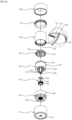
- FIG. 2 is an exploded perspective view when viewed from the upper side of the cosmetic container according to the embodiment of the present disclosure
- FIG. 3 is an exploded perspective view when viewed from the lower side of the cosmetic container according to the embodiment of the present disclosure
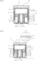
- FIG. 4 is a sectional view taken along line A-A of FIG. 1
- FIG. 5 is a sectional view taken along line B-B of FIG. 1 .
- the rotational discharge-type cosmetic container may include an outer container 10, an inner container 20, a rotary member 30, a rotary operation member 40, an elevating member 50, and a piston 60.
- the outer container 10 has a cylindrical shape with one side open and has a predetermined inner space, and the remaining components, that is, the inner container 20, the rotary member 30, the rotary operation member 40, the elevating member 50 and the piston 60 are inserted into and coupled to the inner space.
- a coupling extension portion 12 may be formed at a center of the inside of the outer container 10.
- the coupling extension portion 12 has a tube shape (which collectively refers to an object having a round and hollow body) extending upward from a top surface of a bottom of the outer container 10, in which an insertion hole 14 is formed at a center thereof, so that at least a part of the inner container 20 is inserted into the insertion hole 14 and the elevating member 50 covers an upper outer side thereof.
- a first locking protrusion 14a locked and coupled to the inner container 20 may protrude from a side wall of the insertion hole 14.
- a rotation limiting protrusion 12a for limiting rotation of the inner container 20 may be formed on an inner circumference of the coupling extension portion 12, and a straight guide protrusion 12b for guiding straight movements of the elevating member 50 may be formed on an outer circumference thereof. It is preferable that the rotation limiting protrusion 12a extends long in a longitudinal direction of the inner container 20, the straight guide protrusion 12b extends long in a moving direction of the elevating member 50, and a plurality of rotation limiting protrusions 12a and straight guide protrusions 12b are formed on the inner circumference and the outer circumference of the coupling extension portion 12, respectively, to stably operate interrelated components.
- a shoulder 70 may be further coupled to one open side of the outer container 10.
- the shoulder 70 may be formed in a ring shape having a predetermined height to have at least a part inserted into the outer container 10 and a remaining part exposed upward from the outer container 10. As shown in FIGS. 4 and 5 , the shoulder 70 blocks a gap between the outer container 10 and the rotary member 30 to prevent foreign substances from being introduced and simultaneously prevent the rotary operation member 40 coupled to the inside of the outer container 10 from being separated.
- the drawing of the cosmetic container according to the embodiment of the present disclosure illustrates that the groove is formed on the inner circumference of the outer container 10 and the protrusion is formed on the outer circumference of the shoulder 70 so as to be coupled to each other, but the present disclosure is not limited thereto.
- Various types of coupling structures such as undercut coupling, forced fitting coupling, and screw coupling may be provided within a range in which the shoulder 70 may be stably fixed and coupled to the outer container 10.
- a container cover 80 for opening or closing the rotary member 30 may be formed on one side of the outer container 10.
- the container cover 80 is detachably fastened to the shoulder 70 while covering the rotary member 30, separated from the shoulder 70 in use to expose the rotary member 30 to the outside, and coupled to the shoulder 70 to protect the rotary member 30 when being stored or carried.
- the container cover 80 may be detachably fastened to the outer container 10 other than the shoulder 70.
- the inner container 20 refers to a storage body in which liquid or gel-type contents are stored, and is inserted and coupled to the inner space of the outer container 10. At least a part of the inner container 20 is inserted and coupled to the coupling extension portion 12 of the outer container 10, restricted in rotation, and fixed inside the outer container 10.
- the inner container 20 may include a storage portion 22 and a coupling portion 24 extending from a center of a bottom of the storage portion 22.
- the storage portion 22 is provided with a predetermined storage space for accommodating contents therein and has one open side, in which the piston 60 is positioned therein.
- the storage portion 22 may be formed on an outer circumference thereof with a first fastening protrusion 22a so as to be rotatably coupled to the rotary member 30, and may be formed on a bottom surface thereof with at least two through-holes 22b through which the elevating member 50 passes.
- the coupling portion 24 is inserted and coupled to the center of the coupling extension portion 12 of the outer container 10.
- the coupling portion 24 is formed on the outer circumference thereof with a rotation limiting groove 24a so as to be fitted into the rotation limiting protrusion 12a of the coupling extension portion 12, and is formed with a second locking protrusion 24b adjacent to the rotation limiting groove 24a so as to be locked and coupled to the first locking protrusion 14a of the coupling extension portion 12. Therefore, when the rotary member 30 is rotated, the inner container 20 may be fixed without being rotated together, and the inner container 20 may be prevented from being separated and deviated from the outer container 10.
- the rotary member 30 is rotatably coupled to an outer side of the inner container 20 and rotatably manipulated by the user to transmit rotational motion to the rotary operation member 40.
- at least a part of the rotary member 30 may be inserted into the outer container 10 and coupled to the rotary operation member 40, and the remaining part thereof may be exposed to the outside of the outer container 10 and rotatably coupled to the inner container 20 while surrounding an upper part of the inner container 20.
- the rotary member 30 has a cylindrical shape with one open side to which the inner container 20 may be inserted, and has an end inserted into the rotary operation member 40.
- a discharge port 32 for discharging the contents stored in the inner container 20 to the outside may be formed in a top surface of the rotary member 30, that is, in an opposite side of the one open side. It is preferable that at least one more discharge ports 32 are provided and include a straight hole elongated from a center of the rotary member 30 toward an edge part.
- the discharge ports 32 are radially spaced apart from each other at a predetermined angle on the top surface of the rotary member 30, and a discharge area or position of the contents may be variously adjusted according to the number of discharge ports 32, the angle spaced apart from the adjacent discharge port 32, and the like.
- the discharge ports 32 may be intensively arranged in a part of the top of the rotary member 30, so that the contents are discharged while being limited to a partial area of the top surface of the rotary member 30.
- the discharge ports 32 may be uniformly arranged over the entire top surface of the rotary member 30, so that the contents are discharged while being widely spread over the entire area of the top surface of the rotary member 30.
- the drawing of the cosmetic container according to the embodiment of the present disclosure illustrates that the two discharge ports 32 are formed and spaced apart from each other at an angle of 90 degrees, but the present disclosure is not limited thereto, and the number of discharge ports 32 and the spaced angle may be modified according to the discharge area and the discharge amount of the contents.
- a discharge space 33 may be formed in the top surface of the rotary member 30, and it is preferable that the discharge space 33 may be formed to be recessed inward from an upper part of the rotary member 30 to prevent the contents discharged from the inner container 20 from flowing outward.
- a plurality of first insertion protrusions 34 may be formed on an inner circumference of an end of the rotary member 30, and it is preferable that the first insertion protrusions 34 may be spaced apart from each other at a predetermined interval along the inner circumference of the rotary member 30 and extend vertically along an insertion direction of the rotary member 30.
- a second fastening protrusion 36 may be formed inward on the inner circumference of the rotary member 30 so as to be rotatably undercut-coupled to the first fastening protrusion 22a. It is preferable that the second fastening protrusion 36 protrudes at a predetermined section along the inner circumference of the rotary member 30.
- discharge guide oblique surfaces 32a and a discharge guide protrusion 32b may be formed adjacent to the discharge port 32.
- the discharge guide oblique surfaces 32a may be inclined at a predetermined angle on both side walls of the discharge port 32, and the discharge guide protrusion 32b may protrude from any one of the discharge guide oblique surfaces 32a toward the inside of the rotary member 30, thereby controlling a direction of the contents discharged with respect to the discharge port 32 having the straight shape.
- the piston 60 is moved by a predetermined section to push the contents upward, and the discharge guide protrusion 32b is simultaneously rotated to sweep an upper surface of the contents upward, so that the contents are more smoothly discharged to the outside through the discharge port 32, and the contents may be discharged in any one direction around the discharge port 32 while being moved and guided by the discharge guide oblique surface 32a inclined at the predetermined angle.
- the rotary operation member 40 is inserted into the outer container 10 and connected to the rotary member 30 so as to be rotated and operated together.
- the rotary operation member 40 connects the rotary member 30 to the elevating member 50 to convert the rotational manipulation of the rotary member 30 into the straight movement of the elevating member 50.
- the rotary operation member 40 may include an inner wall 42 extending upward from a bottom, a first outer wall 44 spaced apart from the inner wall 42 by a predetermined distance and extending upward, and a second outer wall 46 spaced apart from the first outer wall 44 by a predetermined distance and extending upward.
- the inner wall 42 is a hollow cylinder formed inside the rotary operation member 40, has a center into which the coupling extension portion 12 of the outer container 10 and the elevating member 50 are inserted, and has a first screw thread 42a formed on the inner circumference thereof so as to be screw-coupled to the elevating member 50.
- the first outer wall 44 is a cylinder extending to the outside of the inner wall 42, and has a plurality of second insertion protrusions 44a formed on the outer circumference thereof so as to be fitted and coupled to the first insertion protrusion 34 of the rotary member 30. It is preferable that the second insertion protrusions 44a are spaced apart from each other by a predetermined interval along the outer circumference of the first outer wall 44, and extend vertically along the insertion direction of the rotary member 30 like the first insertion protrusion 34.
- the second outer wall 46 is a cylinder expanding to the outside of the first outer wall 44, and the end of the rotary member 30 may be inserted between the first outer wall 44 and the second outer wall 46. Accordingly, the rotary member 30 is inserted between the first outer wall 44 and the second outer wall 46 of the rotary operation member 40 and stably fixed and coupled to each other, so that the rotary operation member 40 may be smoothly operated.
- a plurality of reinforcing ribs 48 may be formed between the inner wall 42 and the first outer wall 46 of the rotary operation member 40 to connect the inner wall 42 to the first outer wall 44.
- the reinforcing ribs 48 radially extend from the outer circumference of the inner wall 42 to the inner circumference of the first outer wall 46, and the number of reinforcing ribs may be appropriately adjusted in consideration of durability and productivity of the rotary operation member 40.
- the elevating member 50 is inserted into the coupling extension portion 12 of the outer container 10 so as to be straight movable, and is screw-coupled to the rotary operation member 40.
- the elevating member 50 is configured to be interworked with the rotation operation of the rotary operation member 40 to ascend or descend in a driving manner by screw fastening, and inserted into the center of the inner wall 42 of the rotary operation member 40 while covering the outer side of the coupling extension portion 12 of the outer container 10.
- a second screw thread 52 is formed on the outer circumference of the elevating member 50 and screw-coupled to the first screw thread 42a of the rotary operation member 40, and accordingly, the elevating member 50 is moved upward or downward about the rotating rotary operation member 40 as an axis.
- a straight guide groove 54 is formed on the inner circumference of the elevating member 50 and fitted to the straight guide protrusion 12b of the outer container 10, and accordingly, the elevating member 50 is straight moved about the coupling extension portion 12 of the outer container 10 as an axis without being rotated together with the rotary operation member 40. It is preferable that the straight guide groove 54 extend straight and long along the moving direction of the elevating member 50 like the straight guide protrusion 12b of the outer container 10.
- the side wall of the elevating member 50 may be divided into at least two parts and inserted into the through-holes 22b of the inner container 20, respectively.
- a slit 56 is formed on the side wall of the elevating member 50 to divide the side wall, and the divided side wall passes through the through-hole 22b so as to be inserted into the inner space of the inner container 20.
- a first coupling protrusion 58 may protrude inward from the inner circumference of the end of the elevating member 50 inserted into the inner space of the inner container 20 so as to be coupled to the piston 60.
- the divided side walls of the elevating member 50 are formed to have a width, a number, and a position corresponding to the through-holes 22b of the inner container 20.
- the piston 60 is formed in the inner container 20 to discharge the contents accommodated in the inner container 20 while being straight moved together with the elevating member 50.
- the piston 60 pushes the contents stored in the inner container 20 in a direction of the discharge port 32 of the rotary member 30 while coming into close contact with the inner circumference of the inner container 20 and discharges the contents to the outside, in which a piston blade 62 coming into close contact with the inner circumference of the inner container 20 may be formed at the edge of the piston 60.
- a second coupling protrusion 68 may be formed on a lower surface of the piston 60, that is, on an opposite side of the surface pushing the contents, so as to be fixedly coupled to the first coupling protrusion 58 of the elevating member 50.
- the one aspect of the present disclosure is operated in the driving manner by screw fastening, in which the rotary member 30 is connected to the elevating member 50 through the rotary operation member 40, and the rotation operation of the rotary member 30 is converted into the straight motion of the elevating member 50 through the rotary operation member 40 to move the piston 60 within the inner container by a predetermined section, thereby using all the contents without leakage, so that the resources can be prevented from being wasted, the contents can be hygienically used, and the contents stored in the inner container 20 can be smoothly discharged to the outside without operational defects during use.
- FIGS. 6 and 7 are views showing an operation process of the rotational discharge-type cosmetic container according to the embodiment of the present disclosure. A process of using the rotational discharge-type cosmetic container according to the embodiment of the present disclosure will be described with reference to the drawings.
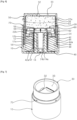
- FIG. 6 is a sectional view illustrating a state in which contents are discharged according to the embodiment of the present disclosure
- FIG. 7 is a perspective view illustrating a state in which the contents are discharged according to the embodiment of the present disclosure.
- the container cover 80 is separated from the outer container 10 to expose the rotary member 30 to the outside.
- the piston 60 coupled to one side of the elevating member 50 pushes the contents toward the discharge port 32 while being moved upward within the inner container 20, and accordingly, as shown in FIG. 7 , a predetermined amount of the contents is discharged to the outside through the discharge port 32.
- the contents discharged to the discharge space 34 of the rotary member 30 are put on a makeup tool such as a puff (not shown) and uniformly applied onto the skin for makeup.
- the rotary member 30 is coupled to the shoulder 70 while being covered by the container cover 80, so as to be stored or carried.
Landscapes
- Engineering & Computer Science (AREA)
- Mechanical Engineering (AREA)
- Containers And Packaging Bodies Having A Special Means To Remove Contents (AREA)
Abstract
Description
- The present invention relates to a cosmetic container and, more specifically, to a rotational discharge-type cosmetic container for converting the rotation operation of the rotary member into straight motion of the elevating member through the rotary operation member to move the piston within the inner container, so that the contents stored in the inner container is smoothly discharged to the outside without leakage.
- Recently, in the rapidly diversifying modem society, both men and women of all ages use cosmetics as necessary. In particular, women use various types of cosmetics and tools with various colors, and various high-quality cosmetics and tools are released on the market day by day through research and development by cosmetics-related companies.
- Depending on the purpose of use, the cosmetics are classified into facial cleansing cosmetics used to remove sebum, waste, and pollutants on the skin surface; basic cosmetics used to appropriately supply moisture and oil to the skin; color cosmetics used to express beautiful colors; hair cosmetics used to remove foreign substances of hair or scalp and simultaneously protect the hair and provide nourishment; and perfume obtained by dissolving fragrance in alcohol or the like and used to give fragrance to others.
- As the above cosmetics are developed, it is also necessary to develop various cosmetic containers capable of containing the cosmetics.
- In general, in order to store and use cosmetics having a liquid or gel form, such as lotion, cream, gel, shampoo and or rinse, containers simply having an opening and closing function have been used in the related art, and accordingly the cosmetics are taken out from the container and applied to the skin by using a finger or a cosmetic tool such as a puff.
- However, according to the cosmetic container in the related art, the cosmetics may be completely exposed to the air and oxidized since the cosmetic container in related art is required to be used while a lid of the container is opened, and the cosmetics may be contaminated by bacteria, viruses, molds, and the like since the puff having contacted with the skin is repeatedly contacted with the cosmetics during use, thereby causing skin troubles or shortening the use period. In addition, in the cosmetic container in the related art, since cosmetics are used by dispensing the cosmetics using a finger or a cosmetic tool such as a puff, the used amount of cosmetics fails to be controlled consistently, thereby resulting in waste and inconvenience in use of the cosmetics.
- Accordingly, a rotational discharge-type cosmetic container, which minimizes deterioration and contamination during using cosmetics, and allows convenience in use and uniformly control the used amount of cosmetics, has been developed.
- As a related art having the above structure,
Korean Registered Patent No. 10-2188196 - However, the related art has a structure in which the rotary member is screw-coupled to the center of the piston and an edge of the piston comes into close contact with an inner wall of the inner case. When the piston does not completely come into close contact with the inner case, the piston may be rotated together with the rotary member at the time of the rotation operation of the rotary bevel and fail to ascend and descend with respect to the rotary member as an axis, thereby causing an operation failure.
- In order to solve the above problems,
Korean Registered Patent No. 10-2213437 - The above related art includes: a cosmetic storage container having an accommodation space for accommodating cosmetics; a lower case portion installed therein with the cosmetic storage container; an upper case portion fastened to the lower case portion so as to be opened and closed; a cosmetic discharge portion formed on an upper part of the cosmetic storage container to serve to discharge the cosmetics; and a cosmetic transfer means for transferring the cosmetics toward the cosmetic discharge portion, wherein the cosmetic transfer means includes: a rotational force applying portion rotated by an external force and provided with a screw connection portion; a driving screw connected to the screw connection portion of the rotational force applying portion so as to be rotated and having a screw thread formed on an outer circumferential surface thereof in a spiral shape; and an elevating member built in the cosmetic storage container and screw-coupled to the driving screw to move and discharge the cosmetics while ascending and descending.
- However, according to the related art, the elevating member for pushing up the cosmetics and the driving screw for moving the elevating member are positioned in the inner space of the cosmetic storage container and screw-coupled to each other, an elevating guide shaft and an elevating guide hole are formed in the cosmetic storage container and the elevating member, respectively, and are fitted with each other in order to limit the rotation of the elevating member. Thus, the cosmetics may be leaked out and wasted through a gap between the elevating member and the driving screw or between the elevating guide shaft and the elevating guide hole.
-
- (Patent document 001)
Korean Registered Patent No. 1 0-2188196 (Published on December 09, 2020 - (Patent document 002)
Korean Registered Patent No. 10-2213437 (Published on February 05,2021 - In order to solve the above problems in the related art, an object of one aspect of the present disclosure is to provide a rotational discharge-type cosmetic container for connecting the rotary member to the elevating member through the rotary operation member and converting the rotation operation of the rotary member into straight motion of the elevating member through the rotary operation member to move the piston within a predetermined section in the inner container, so that the contents stored in the inner container is smoothly discharged to the outside without leakage.
- In order to solve the above object, the one aspect of the present disclosure provides a rotational discharge-type cosmetic container including: an outer container having a coupling extension portion formed therein; an inner container fitted into the coupling extension portion of the outer container so as to be restricted in rotation to accommodate contents therein; a rotary member rotatably coupled to an outer side of the inner container and having at least one discharge port formed therethrough; a rotary operation member connected to the rotary member to be rotated together and having a first screw thread formed thereon; an elevating member screw-coupled to the rotary operation member, inserted into the coupling extension portion of the outer container so as to be straight movable, and having a second screw thread formed thereon; and a piston formed inside the inner container and coupled to one side of the elevating member to push and discharge the contents toward the discharge port while being straight moved together with the elevating member.
- In addition, the outer container has one open side to which a shoulder is further coupled.
- In addition, a container cover for opening or closing the rotary member is further included.
- In addition, the coupling extension portion has a tube shape extending upward from a center of a bottom of the outer container.
- In addition, the coupling extension portion of the outer container is formed on an inner circumference thereof with a rotation limiting protrusion, and the inner container is formed on an outer circumference thereof with a rotation limiting groove, so that the rotation limiting protrusion and the rotation limiting groove are coupled to each other, thereby limiting the rotation of the inner container.
- In addition, the coupling extension portion of the outer container is formed on an outer circumference thereof with a straight guide protrusion, and the elevating member is formed on an inner circumference thereof with a straight guide groove, so that the straight guide protrusion and the straight guide groove are coupled to each other, thereby guiding the straight movement of the elevating member.
- In addition, the coupling extension portion of the outer container is formed at a center thereof with an insertion hole into which at least a part of the inner container is inserted, and the insertion hole and the inner container are formed therein with a first locking protrusion and a second locking protrusion, respectively, so as to be locked and coupled to each other.
- In addition, the rotary member has at least a part exposed from the outer container, and is rotatably coupled to the inner container while surrounding an upper part of the inner container.
- In addition, the discharge port is formed on a top surface of the rotary member and includes a straight hole extending from a center to an edge part of the rotary member.
- In addition, the rotary member is formed therein with a discharge guide protrusion adjacent to the discharge port, and the discharge guide protrusion protrudes inward from the rotary member.
- In addition, the rotary operation member includes an inner wall extending upward from a bottom, a first outer wall spaced apart from the inner wall by a predetermined distance and extending upward, and a second outer wall spaced apart from the first outer wall by a predetermined distance and extending upward.
- In addition, an end of the rotary member is inserted between the first outer wall and the second outer wall of the rotary operation member, and a plurality of first insertion protrusions and second insertion protrusions are formed on the rotary member and the first outer wall, respectively, so as to be inserted and coupled to each other.
- In addition, the elevating member has a side wall divided into at least two parts, and the inner container is formed on a bottom surface thereof with a through-hole, in which the divided side wall passes through the through-hole so as to be inserted into an inner space of the inner container.
- According to the embodiments of the one aspect of the present disclosure, since the sealing between the inner container for storing the contents therein and the piston ascending and descending within the inner container is stably maintained even during operation, all of the contents is used without leakage, so that resources can be prevented from being wasted and the contents can be hygienically used.
- According to the embodiments of the one aspect of the present disclosure, the rotary member operated by a user and the elevating member for moving the piston in a predetermined section are tightly interworked with each other through the rotary operation member, so that a fixed quantity of contents stored in the inner container can be smoothly discharged to the outside without operational errors during use.
-
-
FIG. 1 is a perspective view of a cosmetic container according to the embodiment of the one aspect of the present disclosure. -
FIG. 2 is an exploded perspective view when viewed from the upper side of the cosmetic container according to the embodiment of the one aspect of the present disclosure. -
FIG. 3 is an exploded perspective view when viewed from the lower side of the cosmetic container according to the embodiment of the one aspect of the present disclosure. -
FIG. 4 is a sectional view taken along line A-A ofFIG. 1 . -
FIG. 5 is a sectional view taken along line B-B ofFIG. 1 . -
FIG. 6 is a sectional view illustrating a state in which contents are discharged according to the embodiment of the one aspect of the present disclosure. -
FIG. 7 is a perspective view illustrating a state in which contents are discharged according to the embodiment of the one aspect of the present disclosure. - Hereinafter, the embodiments for implementing the one aspect of the present disclosure will be described detailed description of the one aspect of the present disclosure and the corresponding embodiments refer to the accompanying drawings as examples. These embodiments will be described in detail to enable a person having ordinary skill in the art to sufficiently implement the one aspect of the present disclosure. It will be understood that various embodiments of the one aspect of the present disclosure are different from each other, but need not be exclusive mutually. For example, the specific shapes, structures, and features described herein may be embodied as other embodiments without departing from the idea and scope of the present disclosure in relation to one embodiment. In addition, it will be understood that the position or arrangement of individual components in each disclosed embodiment may be modified without departing from the idea and scope of the present disclosure.
- Accordingly, the detailed description described later is not intended to be taken in a limiting meaning, and the scope of the present disclosure is limited only by the appended claims in addition to all the scope equivalent to that claimed by the claims if appropriately described. In the drawings, similar reference numerals refer to the same or similar functions over several aspects.
- The terms used in the one aspect of the present disclosure are selected as general terms currently widely used as possible while considering functions in the one aspect of the present disclosure, but may vary depending on, for example, the intention or precedent of a person having ordinary skill in the art, and the emergence of new technologies. In addition, in specific cases where the terms may be arbitrarily selected by the applicant, the meaning thereof will be described in detail in the corresponding description of the present disclosure. Therefore, the terms used in the present disclosure will be defined based on the meanings of the terms and the context throughout the present disclosure, other than simple names of the terms.
- In the one aspect of the present disclosure, when a certain part "includes" a certain component, it signifies that other components may be further included, rather than excluding the other components, unless otherwise stated.
- Hereinafter, a rotational discharge-type cosmetic container according to the embodiments of the present disclosure will be described in detail with reference to the accompanying drawings.
-
FIG. 1 is a perspective view of a cosmetic container according to the embodiment of the present disclosure;FIG. 2 is an exploded perspective view when viewed from the upper side of the cosmetic container according to the embodiment of the present disclosure;FIG. 3 is an exploded perspective view when viewed from the lower side of the cosmetic container according to the embodiment of the present disclosure;FIG. 4 is a sectional view taken along line A-A ofFIG. 1 ; andFIG. 5 is a sectional view taken along line B-B ofFIG. 1 . - As shown in the drawings, the rotational discharge-type cosmetic container according to the embodiment of the present disclosure may include an
outer container 10, aninner container 20, arotary member 30, arotary operation member 40, anelevating member 50, and apiston 60. - Each component of the rotational discharge-type cosmetic container according to the embodiment of the present disclosure will be described as follows.
- The
outer container 10 has a cylindrical shape with one side open and has a predetermined inner space, and the remaining components, that is, theinner container 20, therotary member 30, therotary operation member 40, the elevatingmember 50 and thepiston 60 are inserted into and coupled to the inner space. - As shown in
FIG. 2 , acoupling extension portion 12 may be formed at a center of the inside of theouter container 10. Thecoupling extension portion 12 has a tube shape (which collectively refers to an object having a round and hollow body) extending upward from a top surface of a bottom of theouter container 10, in which aninsertion hole 14 is formed at a center thereof, so that at least a part of theinner container 20 is inserted into theinsertion hole 14 and the elevatingmember 50 covers an upper outer side thereof. A first locking protrusion 14a locked and coupled to theinner container 20 may protrude from a side wall of theinsertion hole 14. - In addition, a
rotation limiting protrusion 12a for limiting rotation of theinner container 20 may be formed on an inner circumference of thecoupling extension portion 12, and astraight guide protrusion 12b for guiding straight movements of the elevatingmember 50 may be formed on an outer circumference thereof. It is preferable that therotation limiting protrusion 12a extends long in a longitudinal direction of theinner container 20, thestraight guide protrusion 12b extends long in a moving direction of the elevatingmember 50, and a plurality ofrotation limiting protrusions 12a andstraight guide protrusions 12b are formed on the inner circumference and the outer circumference of thecoupling extension portion 12, respectively, to stably operate interrelated components. - Meanwhile, a
shoulder 70 may be further coupled to one open side of theouter container 10. Theshoulder 70 may be formed in a ring shape having a predetermined height to have at least a part inserted into theouter container 10 and a remaining part exposed upward from theouter container 10. As shown inFIGS. 4 and 5 , theshoulder 70 blocks a gap between theouter container 10 and therotary member 30 to prevent foreign substances from being introduced and simultaneously prevent therotary operation member 40 coupled to the inside of theouter container 10 from being separated. The drawing of the cosmetic container according to the embodiment of the present disclosure illustrates that the groove is formed on the inner circumference of theouter container 10 and the protrusion is formed on the outer circumference of theshoulder 70 so as to be coupled to each other, but the present disclosure is not limited thereto. Various types of coupling structures such as undercut coupling, forced fitting coupling, and screw coupling may be provided within a range in which theshoulder 70 may be stably fixed and coupled to theouter container 10. - In addition, a
container cover 80 for opening or closing therotary member 30 may be formed on one side of theouter container 10. Thecontainer cover 80 is detachably fastened to theshoulder 70 while covering therotary member 30, separated from theshoulder 70 in use to expose therotary member 30 to the outside, and coupled to theshoulder 70 to protect therotary member 30 when being stored or carried. Thecontainer cover 80 may be detachably fastened to theouter container 10 other than theshoulder 70. - The
inner container 20 refers to a storage body in which liquid or gel-type contents are stored, and is inserted and coupled to the inner space of theouter container 10. At least a part of theinner container 20 is inserted and coupled to thecoupling extension portion 12 of theouter container 10, restricted in rotation, and fixed inside theouter container 10. - As shown in
FIGS. 2 and3 , theinner container 20 may include astorage portion 22 and acoupling portion 24 extending from a center of a bottom of thestorage portion 22. - The
storage portion 22 is provided with a predetermined storage space for accommodating contents therein and has one open side, in which thepiston 60 is positioned therein. Thestorage portion 22 may be formed on an outer circumference thereof with afirst fastening protrusion 22a so as to be rotatably coupled to therotary member 30, and may be formed on a bottom surface thereof with at least two through-holes 22b through which the elevatingmember 50 passes. - The
coupling portion 24 is inserted and coupled to the center of thecoupling extension portion 12 of theouter container 10. In other words, thecoupling portion 24 is formed on the outer circumference thereof with arotation limiting groove 24a so as to be fitted into therotation limiting protrusion 12a of thecoupling extension portion 12, and is formed with asecond locking protrusion 24b adjacent to therotation limiting groove 24a so as to be locked and coupled to the first locking protrusion 14a of thecoupling extension portion 12. Therefore, when therotary member 30 is rotated, theinner container 20 may be fixed without being rotated together, and theinner container 20 may be prevented from being separated and deviated from theouter container 10. - The
rotary member 30 is rotatably coupled to an outer side of theinner container 20 and rotatably manipulated by the user to transmit rotational motion to therotary operation member 40. In other words, as shown inFIGS. 4 and 5 , at least a part of therotary member 30 may be inserted into theouter container 10 and coupled to therotary operation member 40, and the remaining part thereof may be exposed to the outside of theouter container 10 and rotatably coupled to theinner container 20 while surrounding an upper part of theinner container 20. - The
rotary member 30 has a cylindrical shape with one open side to which theinner container 20 may be inserted, and has an end inserted into therotary operation member 40. - As shown in
FIG. 2 , adischarge port 32 for discharging the contents stored in theinner container 20 to the outside may be formed in a top surface of therotary member 30, that is, in an opposite side of the one open side. It is preferable that at least onemore discharge ports 32 are provided and include a straight hole elongated from a center of therotary member 30 toward an edge part. Thedischarge ports 32 are radially spaced apart from each other at a predetermined angle on the top surface of therotary member 30, and a discharge area or position of the contents may be variously adjusted according to the number ofdischarge ports 32, the angle spaced apart from theadjacent discharge port 32, and the like. For example, thedischarge ports 32 may be intensively arranged in a part of the top of therotary member 30, so that the contents are discharged while being limited to a partial area of the top surface of therotary member 30. On the contrary, thedischarge ports 32 may be uniformly arranged over the entire top surface of therotary member 30, so that the contents are discharged while being widely spread over the entire area of the top surface of therotary member 30. The drawing of the cosmetic container according to the embodiment of the present disclosure illustrates that the twodischarge ports 32 are formed and spaced apart from each other at an angle of 90 degrees, but the present disclosure is not limited thereto, and the number ofdischarge ports 32 and the spaced angle may be modified according to the discharge area and the discharge amount of the contents. - A
discharge space 33 may be formed in the top surface of therotary member 30, and it is preferable that thedischarge space 33 may be formed to be recessed inward from an upper part of therotary member 30 to prevent the contents discharged from theinner container 20 from flowing outward. - As shown in
FIG. 3 , a plurality offirst insertion protrusions 34 may be formed on an inner circumference of an end of therotary member 30, and it is preferable that thefirst insertion protrusions 34 may be spaced apart from each other at a predetermined interval along the inner circumference of therotary member 30 and extend vertically along an insertion direction of therotary member 30. - A
second fastening protrusion 36 may be formed inward on the inner circumference of therotary member 30 so as to be rotatably undercut-coupled to thefirst fastening protrusion 22a. It is preferable that thesecond fastening protrusion 36 protrudes at a predetermined section along the inner circumference of therotary member 30. - Meanwhile, as shown in a partially enlarged view of
FIG. 5 , discharge guideoblique surfaces 32a and adischarge guide protrusion 32b may be formed adjacent to thedischarge port 32. The discharge guideoblique surfaces 32a may be inclined at a predetermined angle on both side walls of thedischarge port 32, and thedischarge guide protrusion 32b may protrude from any one of the discharge guideoblique surfaces 32a toward the inside of therotary member 30, thereby controlling a direction of the contents discharged with respect to thedischarge port 32 having the straight shape. In other words, when therotary member 30 is rotated, thepiston 60 is moved by a predetermined section to push the contents upward, and thedischarge guide protrusion 32b is simultaneously rotated to sweep an upper surface of the contents upward, so that the contents are more smoothly discharged to the outside through thedischarge port 32, and the contents may be discharged in any one direction around thedischarge port 32 while being moved and guided by the discharge guideoblique surface 32a inclined at the predetermined angle. - The
rotary operation member 40 is inserted into theouter container 10 and connected to therotary member 30 so as to be rotated and operated together. Therotary operation member 40 connects therotary member 30 to the elevatingmember 50 to convert the rotational manipulation of therotary member 30 into the straight movement of the elevatingmember 50. - As shown in
FIG. 2 , Therotary operation member 40 may include aninner wall 42 extending upward from a bottom, a firstouter wall 44 spaced apart from theinner wall 42 by a predetermined distance and extending upward, and a secondouter wall 46 spaced apart from the firstouter wall 44 by a predetermined distance and extending upward. - The
inner wall 42 is a hollow cylinder formed inside therotary operation member 40, has a center into which thecoupling extension portion 12 of theouter container 10 and the elevatingmember 50 are inserted, and has afirst screw thread 42a formed on the inner circumference thereof so as to be screw-coupled to the elevatingmember 50. - The first
outer wall 44 is a cylinder extending to the outside of theinner wall 42, and has a plurality ofsecond insertion protrusions 44a formed on the outer circumference thereof so as to be fitted and coupled to thefirst insertion protrusion 34 of therotary member 30. It is preferable that thesecond insertion protrusions 44a are spaced apart from each other by a predetermined interval along the outer circumference of the firstouter wall 44, and extend vertically along the insertion direction of therotary member 30 like thefirst insertion protrusion 34. - The second
outer wall 46 is a cylinder expanding to the outside of the firstouter wall 44, and the end of therotary member 30 may be inserted between the firstouter wall 44 and the secondouter wall 46. Accordingly, therotary member 30 is inserted between the firstouter wall 44 and the secondouter wall 46 of therotary operation member 40 and stably fixed and coupled to each other, so that therotary operation member 40 may be smoothly operated. - Meanwhile, a plurality of reinforcing
ribs 48 may be formed between theinner wall 42 and the firstouter wall 46 of therotary operation member 40 to connect theinner wall 42 to the firstouter wall 44. The reinforcingribs 48 radially extend from the outer circumference of theinner wall 42 to the inner circumference of the firstouter wall 46, and the number of reinforcing ribs may be appropriately adjusted in consideration of durability and productivity of therotary operation member 40. - The elevating
member 50 is inserted into thecoupling extension portion 12 of theouter container 10 so as to be straight movable, and is screw-coupled to therotary operation member 40. In other words, the elevatingmember 50 is configured to be interworked with the rotation operation of therotary operation member 40 to ascend or descend in a driving manner by screw fastening, and inserted into the center of theinner wall 42 of therotary operation member 40 while covering the outer side of thecoupling extension portion 12 of theouter container 10. - A
second screw thread 52 is formed on the outer circumference of the elevatingmember 50 and screw-coupled to thefirst screw thread 42a of therotary operation member 40, and accordingly, the elevatingmember 50 is moved upward or downward about the rotatingrotary operation member 40 as an axis. Astraight guide groove 54 is formed on the inner circumference of the elevatingmember 50 and fitted to thestraight guide protrusion 12b of theouter container 10, and accordingly, the elevatingmember 50 is straight moved about thecoupling extension portion 12 of theouter container 10 as an axis without being rotated together with therotary operation member 40. It is preferable that thestraight guide groove 54 extend straight and long along the moving direction of the elevatingmember 50 like thestraight guide protrusion 12b of theouter container 10. - Meanwhile, the side wall of the elevating
member 50 may be divided into at least two parts and inserted into the through-holes 22b of theinner container 20, respectively. In other words, aslit 56 is formed on the side wall of the elevatingmember 50 to divide the side wall, and the divided side wall passes through the through-hole 22b so as to be inserted into the inner space of theinner container 20. This is for positioning at least a part of the elevatingmember 50 into theinner container 20 so as to be connected to thepiston 60. Afirst coupling protrusion 58 may protrude inward from the inner circumference of the end of the elevatingmember 50 inserted into the inner space of theinner container 20 so as to be coupled to thepiston 60. It is preferable that the divided side walls of the elevatingmember 50 are formed to have a width, a number, and a position corresponding to the through-holes 22b of theinner container 20. - The
piston 60 is formed in theinner container 20 to discharge the contents accommodated in theinner container 20 while being straight moved together with the elevatingmember 50. - The
piston 60 pushes the contents stored in theinner container 20 in a direction of thedischarge port 32 of therotary member 30 while coming into close contact with the inner circumference of theinner container 20 and discharges the contents to the outside, in which apiston blade 62 coming into close contact with the inner circumference of theinner container 20 may be formed at the edge of thepiston 60. - Meanwhile, a
second coupling protrusion 68 may be formed on a lower surface of thepiston 60, that is, on an opposite side of the surface pushing the contents, so as to be fixedly coupled to thefirst coupling protrusion 58 of the elevatingmember 50. - As described above, the one aspect of the present disclosure is operated in the driving manner by screw fastening, in which the
rotary member 30 is connected to the elevatingmember 50 through therotary operation member 40, and the rotation operation of therotary member 30 is converted into the straight motion of the elevatingmember 50 through therotary operation member 40 to move thepiston 60 within the inner container by a predetermined section, thereby using all the contents without leakage, so that the resources can be prevented from being wasted, the contents can be hygienically used, and the contents stored in theinner container 20 can be smoothly discharged to the outside without operational defects during use. -
FIGS. 6 and 7 are views showing an operation process of the rotational discharge-type cosmetic container according to the embodiment of the present disclosure. A process of using the rotational discharge-type cosmetic container according to the embodiment of the present disclosure will be described with reference to the drawings. -
FIG. 6 is a sectional view illustrating a state in which contents are discharged according to the embodiment of the present disclosure; andFIG. 7 is a perspective view illustrating a state in which the contents are discharged according to the embodiment of the present disclosure. - In order to use the rotational discharge-type cosmetic container according to the embodiment of the present disclosure, first, the
container cover 80 is separated from theouter container 10 to expose therotary member 30 to the outside. - Thereafter, as shown in
FIG. 6 , when therotary member 30 is rotated in any one direction, therotary operation member 40 connected to therotary member 30 is rotated together. However, the rotation of theinner container 20 and the elevatingmember 50 is limited by theouter container 10 held by the user, and thus the elevatingmember 50 screw-coupled to therotary operation member 40 is gradually moved upward in proportion to the rotation section of therotary operation member 40. - At the same time, the
piston 60 coupled to one side of the elevatingmember 50 pushes the contents toward thedischarge port 32 while being moved upward within theinner container 20, and accordingly, as shown inFIG. 7 , a predetermined amount of the contents is discharged to the outside through thedischarge port 32. - Thereafter, the contents discharged to the
discharge space 34 of therotary member 30 are put on a makeup tool such as a puff (not shown) and uniformly applied onto the skin for makeup. - After the makeup is finished, the
rotary member 30 is coupled to theshoulder 70 while being covered by thecontainer cover 80, so as to be stored or carried. - As described above, the one aspect of the present disclosure has been described through the specific features, such as specific components, the limited embodiments and the drawings, but these are provided only for further general understanding of the present disclosure, and the one aspect of the present disclosure is not limited to the above embodiments, and various modifications and variations may be made by the person having ordinary skill in the art from the above description. Therefore, the idea of the present disclosure may not be limited to the described embodiments, and the claims described below and anything equal or equivalent to the claims may belong to the scope of the idea of the present disclosure.
-
10: Outer container 12: Coupling extension portion 20: Inner container 22: Storage portion 24: Coupling portion 30: Rotary member 32: Discharge port 40: Rotary operation member 42: Inner wall 42a: First screw thread 44: First outer wall 46: Second outer wall 50: Elevating member 52: Second screw thread 60: Piston 70: Shoulder 80: Container cover
Claims (13)
- A rotational discharge-type cosmetic container comprising:an outer container having a coupling extension portion formed therein;an inner container fitted into the coupling extension portion of the outer container so as to be restricted in rotation to accommodate contents therein;a rotary member rotatably coupled to an outer side of the inner container and having at least one discharge port formed therethrough;a rotary operation member connected to the rotary member to be rotated together and having a first screw thread formed thereon;an elevating member screw-coupled to the rotary operation member, inserted into the coupling extension portion of the outer container so as to be movable in a straight line, and having a second screw thread formed thereon; anda piston formed inside the inner container and coupled to one side of the elevating member to push and discharge the contents toward the discharge port while being moved in a straight line together with the elevating member.
- The rotational discharge-type cosmetic container of claim 1, wherein the outer container has one open side to which a shoulder is further coupled.
- The rotational discharge-type cosmetic container of claim 1, further comprising:
a container cover for opening or closing the rotary member. - The rotational discharge-type cosmetic container of claim 1, wherein the coupling extension portion has a tube shape extending upward from a center of a bottom of the outer container.
- The rotational discharge-type cosmetic container of claim 1, wherein the coupling extension portion of the outer container is formed on an inner circumference thereof with a rotation limiting protrusion, and the inner container is formed on an outer circumference thereof with a rotation limiting groove, so that the rotation limiting protrusion and the rotation limiting groove are coupled to each other, thereby limiting the rotation of the inner container.
- The rotational discharge-type cosmetic container of claim 1, wherein the coupling extension portion of the outer container is formed on an outer circumference thereof with a straight guide protrusion, and the elevating member is formed on an inner circumference thereof with a straight guide groove, so that the straight guide protrusion and the straight guide groove are coupled to each other, thereby guiding the straight movement of the elevating member.
- The rotational discharge-type cosmetic container of claim 1, wherein the coupling extension portion of the outer container is formed at a center thereof with an insertion hole into which at least a part of the inner container is inserted, and the insertion hole and the inner container are formed therein with a first locking protrusion and a second locking protrusion, respectively, so as to be locked and coupled to each other.
- The rotational discharge-type cosmetic container of claim 1, wherein the rotary member has at least a part exposed from the outer container, and is rotatably coupled to the inner container while surrounding an upper part of the inner container.
- The rotational discharge-type cosmetic container of claim 1, wherein the discharge port is formed on a top surface of the rotary member and includes a straight hole extending from a center to an edge part of the rotary member.
- The rotational discharge-type cosmetic container of claim 1, wherein the rotary member is formed therein with a discharge guide protrusion adjacent to the discharge port, and the discharge guide protrusion protrudes inward from the rotary member.
- The rotational discharge-type cosmetic container of claim 1, wherein the rotary operation member includes an inner wall extending upward from a bottom thereof, a first outer wall spaced apart from the inner wall by a predetermined distance and extending upward, and a second outer wall spaced apart from the first outer wall by a predetermined distance and extending upward.
- The rotational discharge-type cosmetic container of claim 11, wherein the rotary member has an end inserted between the first outer wall and the second outer wall of the rotary operation member, and a plurality of first insertion protrusions and second insertion protrusions are formed on the rotary member and the first outer wall, respectively, so as to be inserted and coupled to each other.
- The rotational discharge-type cosmetic container of claim 1, wherein the elevating member has a side wall divided into at least two parts, and the inner container is formed on a bottom surface thereof with a through-hole, in which the divided side wall passes through the through-hole so as to be inserted into an inner space of the inner container.
Applications Claiming Priority (2)
| Application Number | Priority Date | Filing Date | Title |
|---|---|---|---|
| KR1020210153227A KR102518506B1 (en) | 2021-11-09 | 2021-11-09 | Rotating discharge type cosmetics container |
| PCT/KR2022/015926 WO2023085634A1 (en) | 2021-11-09 | 2022-10-19 | Rotational discharge-type cosmetic container |
Publications (3)
| Publication Number | Publication Date |
|---|---|
| EP4410148A1 true EP4410148A1 (en) | 2024-08-07 |
| EP4410148A4 EP4410148A4 (en) | 2025-02-19 |
| EP4410148B1 EP4410148B1 (en) | 2025-12-10 |
Family
ID=85884865
Family Applications (1)
| Application Number | Title | Priority Date | Filing Date |
|---|---|---|---|
| EP22893057.4A Active EP4410148B1 (en) | 2021-11-09 | 2022-10-19 | Rotational discharge-type cosmetic container |
Country Status (6)
| Country | Link |
|---|---|
| US (1) | US12617603B2 (en) |
| EP (1) | EP4410148B1 (en) |
| JP (1) | JP7658033B2 (en) |
| KR (1) | KR102518506B1 (en) |
| CN (1) | CN118102944A (en) |
| WO (1) | WO2023085634A1 (en) |
Families Citing this family (7)
| Publication number | Priority date | Publication date | Assignee | Title |
|---|---|---|---|---|
| KR102826892B1 (en) * | 2023-06-07 | 2025-06-30 | 펌텍코리아(주) | Rotating discharge type cosmetics container |
| KR102823768B1 (en) * | 2023-11-23 | 2025-06-23 | 주식회사 삼화 | Grinding container |
| KR102796881B1 (en) * | 2024-01-04 | 2025-04-17 | 펌텍코리아(주) | Rotating discharge container |
| KR102925674B1 (en) * | 2024-02-28 | 2026-02-10 | 펌텍코리아(주) | Rotating discharge container |
| KR102892801B1 (en) | 2024-04-08 | 2025-11-28 | 주식회사 씨티케이 | Cosmetics container having a structure that doubles the lifting operation distance |
| KR102921071B1 (en) * | 2025-01-06 | 2026-02-04 | 주식회사 삼화 | Grinding container that allows meticulous operation |
| KR102947022B1 (en) * | 2025-03-20 | 2026-04-02 | 주식회사 위미에르 | Turning Ejection Bottle |
Family Cites Families (17)
| Publication number | Priority date | Publication date | Assignee | Title |
|---|---|---|---|---|
| DE8700756U1 (en) | 1987-01-16 | 1987-05-27 | Koeppe, Tobias, Dipl.-Designer, 3000 Hannover | Cream jar |
| JP2006219174A (en) | 2005-02-14 | 2006-08-24 | Kaishin:Kk | Contents extrusion container |
| JP5267858B2 (en) * | 2008-09-06 | 2013-08-21 | フィグラ株式会社 | High viscosity liquid cosmetic discharge container |
| US20120085788A1 (en) * | 2010-10-08 | 2012-04-12 | Yu-Chu Lu | Vacuum Cream Container that is Operable by Rotation to Squeeze Cream Outward |
| KR20130001280U (en) * | 2011-08-17 | 2013-02-27 | 펌텍코리아 (주) | Rotate pressing out type cosmetic container |
| KR101383079B1 (en) * | 2013-01-10 | 2014-04-08 | 김영호 | Cosmetic container having liquid cosmetic rotate discharge |
| KR200476045Y1 (en) * | 2013-09-09 | 2015-01-28 | 김영호 | A Cosmetic Liquid Pumping Unit |
| KR200489964Y1 (en) * | 2018-02-22 | 2019-09-02 | 주식회사 엘지생활건강 | Cosmetic Device |
| WO2020050452A1 (en) * | 2018-09-06 | 2020-03-12 | 주식회사 삼화플라스틱 | Airless cosmetic container |
| KR102188196B1 (en) | 2019-04-15 | 2020-12-09 | 주식회사 삼화 | Cosmetic container |
| KR102348996B1 (en) * | 2019-09-03 | 2022-01-10 | 주식회사 코스메카코리아 | Solid cosmetics container filled with solid cosmetic material |
| WO2021153949A1 (en) * | 2020-01-29 | 2021-08-05 | 정재용 | Stick-type cosmetic container |
| KR102320900B1 (en) * | 2020-03-12 | 2021-11-04 | 주식회사 삼화 | Dial type container |
| KR102279516B1 (en) | 2020-03-24 | 2021-07-21 | 주식회사 삼화 | Grinding container |
| KR102213437B1 (en) | 2020-10-14 | 2021-02-05 | 주식회사 시암 | Cosmetics container |
| KR102741351B1 (en) * | 2021-10-01 | 2024-12-12 | 펌텍코리아 (주) | A stick container for preventing residual amount with a sealed structure |
| US11779095B2 (en) * | 2021-12-09 | 2023-10-10 | Kr Co., Ltd. | Container for stick type content |
-
2021
- 2021-11-09 KR KR1020210153227A patent/KR102518506B1/en active Active
-
2022
- 2022-10-19 EP EP22893057.4A patent/EP4410148B1/en active Active
- 2022-10-19 CN CN202280069949.XA patent/CN118102944A/en active Pending
- 2022-10-19 US US18/702,736 patent/US12617603B2/en active Active
- 2022-10-19 WO PCT/KR2022/015926 patent/WO2023085634A1/en not_active Ceased
- 2022-10-19 JP JP2024525368A patent/JP7658033B2/en active Active
Also Published As
| Publication number | Publication date |
|---|---|
| JP2024538275A (en) | 2024-10-18 |
| JP7658033B2 (en) | 2025-04-07 |
| EP4410148A4 (en) | 2025-02-19 |
| US20240409299A1 (en) | 2024-12-12 |
| US12617603B2 (en) | 2026-05-05 |
| EP4410148B1 (en) | 2025-12-10 |
| KR102518506B1 (en) | 2023-04-05 |
| CN118102944A (en) | 2024-05-28 |
| WO2023085634A1 (en) | 2023-05-19 |
Similar Documents
| Publication | Publication Date | Title |
|---|---|---|
| EP4410148B1 (en) | Rotational discharge-type cosmetic container | |
| KR102741351B1 (en) | A stick container for preventing residual amount with a sealed structure | |
| EP3287039B1 (en) | Cosmetic container having hiding/revealing pump outlet | |
| KR102826892B1 (en) | Rotating discharge type cosmetics container | |
| JPH1170976A (en) | Equipment for containing two components | |
| KR102499659B1 (en) | Cosmetic case with refill structure | |
| EP3766379A1 (en) | Compact container having improved opening/closing structure for different cosmetic materials | |
| KR200284550Y1 (en) | Dyeing device | |
| KR101049783B1 (en) | Rotating Extrusion Cosmetic Container with Leak-proof Function | |
| EP3047753B1 (en) | Liquid content container comprising tension member | |
| WO2022196420A1 (en) | Container | |
| KR200284551Y1 (en) | Device for mixing a hairdye | |
| CN113423652A (en) | Device for packaging two products separately | |
| US6148995A (en) | Device and method for combining at least two products | |
| EP4663068A1 (en) | Rotating discharge-type cosmetic container | |
| KR102796881B1 (en) | Rotating discharge container | |
| KR102925674B1 (en) | Rotating discharge container | |
| KR20190008655A (en) | Stick type cosmetic container which can use different contents | |
| WO2007017171A1 (en) | Cosmetic container with integrated mixing insert | |
| KR102678134B1 (en) | Cosmetic container with makeup tools | |
| KR102656867B1 (en) | Cosmetic container | |
| JP7749514B2 (en) | Dispensing container | |
| KR102797515B1 (en) | Stick-type cosmetic container | |
| KR20250122682A (en) | Button pressurized constant-quantity discharge container | |
| KR20250154774A (en) | Cosmetic container with hinge operating structure |
Legal Events
| Date | Code | Title | Description |
|---|---|---|---|
| STAA | Information on the status of an ep patent application or granted ep patent |
Free format text: STATUS: THE INTERNATIONAL PUBLICATION HAS BEEN MADE |
|
| PUAI | Public reference made under article 153(3) epc to a published international application that has entered the european phase |
Free format text: ORIGINAL CODE: 0009012 |
|
| STAA | Information on the status of an ep patent application or granted ep patent |
Free format text: STATUS: REQUEST FOR EXAMINATION WAS MADE |
|
| 17P | Request for examination filed |
Effective date: 20240429 |
|
| AK | Designated contracting states |
Kind code of ref document: A1 Designated state(s): AL AT BE BG CH CY CZ DE DK EE ES FI FR GB GR HR HU IE IS IT LI LT LU LV MC ME MK MT NL NO PL PT RO RS SE SI SK SM TR |
|
| DAV | Request for validation of the european patent (deleted) | ||
| DAX | Request for extension of the european patent (deleted) | ||
| A4 | Supplementary search report drawn up and despatched |
Effective date: 20250121 |
|
| RIC1 | Information provided on ipc code assigned before grant |
Ipc: A45D 40/26 20060101ALI20250115BHEP Ipc: A45D 40/04 20060101ALI20250115BHEP Ipc: A45D 34/04 20060101ALI20250115BHEP Ipc: A45D 40/00 20060101AFI20250115BHEP |
|
| GRAP | Despatch of communication of intention to grant a patent |
Free format text: ORIGINAL CODE: EPIDOSNIGR1 |
|
| STAA | Information on the status of an ep patent application or granted ep patent |
Free format text: STATUS: GRANT OF PATENT IS INTENDED |
|
| INTG | Intention to grant announced |
Effective date: 20250723 |
|
| GRAS | Grant fee paid |
Free format text: ORIGINAL CODE: EPIDOSNIGR3 |
|
| GRAA | (expected) grant |
Free format text: ORIGINAL CODE: 0009210 |
|
| STAA | Information on the status of an ep patent application or granted ep patent |
Free format text: STATUS: THE PATENT HAS BEEN GRANTED |
|
| AK | Designated contracting states |
Kind code of ref document: B1 Designated state(s): AL AT BE BG CH CY CZ DE DK EE ES FI FR GB GR HR HU IE IS IT LI LT LU LV MC ME MK MT NL NO PL PT RO RS SE SI SK SM TR |
|
| REG | Reference to a national code |
Ref country code: CH Ref legal event code: F10 Free format text: ST27 STATUS EVENT CODE: U-0-0-F10-F00 (AS PROVIDED BY THE NATIONAL OFFICE) Effective date: 20251210 Ref country code: GB Ref legal event code: FG4D |
|
| REG | Reference to a national code |
Ref country code: DE Ref legal event code: R096 Ref document number: 602022026806 Country of ref document: DE |
|
| REG | Reference to a national code |
Ref country code: IE Ref legal event code: FG4D |
|
| PG25 | Lapsed in a contracting state [announced via postgrant information from national office to epo] |
Ref country code: ES Free format text: LAPSE BECAUSE OF FAILURE TO SUBMIT A TRANSLATION OF THE DESCRIPTION OR TO PAY THE FEE WITHIN THE PRESCRIBED TIME-LIMIT Effective date: 20251210 |
|
| REG | Reference to a national code |
Ref country code: LT Ref legal event code: MG9D |
|
| PG25 | Lapsed in a contracting state [announced via postgrant information from national office to epo] |
Ref country code: NO Free format text: LAPSE BECAUSE OF FAILURE TO SUBMIT A TRANSLATION OF THE DESCRIPTION OR TO PAY THE FEE WITHIN THE PRESCRIBED TIME-LIMIT Effective date: 20260310 |
|
| PG25 | Lapsed in a contracting state [announced via postgrant information from national office to epo] |
Ref country code: FI Free format text: LAPSE BECAUSE OF FAILURE TO SUBMIT A TRANSLATION OF THE DESCRIPTION OR TO PAY THE FEE WITHIN THE PRESCRIBED TIME-LIMIT Effective date: 20251210 Ref country code: HR Free format text: LAPSE BECAUSE OF FAILURE TO SUBMIT A TRANSLATION OF THE DESCRIPTION OR TO PAY THE FEE WITHIN THE PRESCRIBED TIME-LIMIT Effective date: 20251210 |
|
| REG | Reference to a national code |
Ref country code: NL Ref legal event code: MP Effective date: 20251210 |
|
| PG25 | Lapsed in a contracting state [announced via postgrant information from national office to epo] |
Ref country code: RS Free format text: LAPSE BECAUSE OF FAILURE TO SUBMIT A TRANSLATION OF THE DESCRIPTION OR TO PAY THE FEE WITHIN THE PRESCRIBED TIME-LIMIT Effective date: 20260310 |
|
| PG25 | Lapsed in a contracting state [announced via postgrant information from national office to epo] |
Ref country code: LV Free format text: LAPSE BECAUSE OF FAILURE TO SUBMIT A TRANSLATION OF THE DESCRIPTION OR TO PAY THE FEE WITHIN THE PRESCRIBED TIME-LIMIT Effective date: 20251210 |
|
| PG25 | Lapsed in a contracting state [announced via postgrant information from national office to epo] |
Ref country code: BG Free format text: LAPSE BECAUSE OF FAILURE TO SUBMIT A TRANSLATION OF THE DESCRIPTION OR TO PAY THE FEE WITHIN THE PRESCRIBED TIME-LIMIT Effective date: 20251210 |