EP4408082A1 - Control method and apparatus for transmission power of pucch and terminal - Google Patents
Control method and apparatus for transmission power of pucch and terminal Download PDFInfo
- Publication number
- EP4408082A1 EP4408082A1 EP22872205.4A EP22872205A EP4408082A1 EP 4408082 A1 EP4408082 A1 EP 4408082A1 EP 22872205 A EP22872205 A EP 22872205A EP 4408082 A1 EP4408082 A1 EP 4408082A1
- Authority
- EP
- European Patent Office
- Prior art keywords
- pucch
- bit number
- ack
- harq
- uci
- Prior art date
- Legal status (The legal status is an assumption and is not a legal conclusion. Google has not performed a legal analysis and makes no representation as to the accuracy of the status listed.)
- Pending
Links
Images

Classifications
-
- H—ELECTRICITY
- H04—ELECTRIC COMMUNICATION TECHNIQUE
- H04W—WIRELESS COMMUNICATION NETWORKS
- H04W52/00—Power management, e.g. Transmission Power Control [TPC] or power classes
- H04W52/04—Transmission power control [TPC]
- H04W52/06—TPC algorithms
- H04W52/14—Separate analysis of uplink or downlink
-
- H—ELECTRICITY
- H04—ELECTRIC COMMUNICATION TECHNIQUE
- H04L—TRANSMISSION OF DIGITAL INFORMATION, e.g. TELEGRAPHIC COMMUNICATION
- H04L1/00—Arrangements for detecting or preventing errors in the information received
- H04L1/12—Arrangements for detecting or preventing errors in the information received by using return channel
- H04L1/16—Arrangements for detecting or preventing errors in the information received by using return channel in which the return channel carries supervisory signals, e.g. repetition request signals
- H04L1/1607—Details of the supervisory signal
- H04L1/1671—Details of the supervisory signal the supervisory signal being transmitted together with control information
-
- H—ELECTRICITY
- H04—ELECTRIC COMMUNICATION TECHNIQUE
- H04L—TRANSMISSION OF DIGITAL INFORMATION, e.g. TELEGRAPHIC COMMUNICATION
- H04L1/00—Arrangements for detecting or preventing errors in the information received
- H04L1/12—Arrangements for detecting or preventing errors in the information received by using return channel
- H04L1/16—Arrangements for detecting or preventing errors in the information received by using return channel in which the return channel carries supervisory signals, e.g. repetition request signals
- H04L1/18—Automatic repetition systems, e.g. Van Duuren systems
- H04L1/1812—Hybrid protocols; Hybrid automatic repeat request [HARQ]
-
- H—ELECTRICITY
- H04—ELECTRIC COMMUNICATION TECHNIQUE
- H04L—TRANSMISSION OF DIGITAL INFORMATION, e.g. TELEGRAPHIC COMMUNICATION
- H04L1/00—Arrangements for detecting or preventing errors in the information received
- H04L1/12—Arrangements for detecting or preventing errors in the information received by using return channel
- H04L1/16—Arrangements for detecting or preventing errors in the information received by using return channel in which the return channel carries supervisory signals, e.g. repetition request signals
- H04L1/18—Automatic repetition systems, e.g. Van Duuren systems
- H04L1/1829—Arrangements specially adapted for the receiver end
- H04L1/1861—Physical mapping arrangements
-
- H—ELECTRICITY
- H04—ELECTRIC COMMUNICATION TECHNIQUE
- H04L—TRANSMISSION OF DIGITAL INFORMATION, e.g. TELEGRAPHIC COMMUNICATION
- H04L5/00—Arrangements affording multiple use of the transmission path
- H04L5/003—Arrangements for allocating sub-channels of the transmission path
- H04L5/0053—Allocation of signalling, i.e. of overhead other than pilot signals
- H04L5/0055—Physical resource allocation for ACK/NACK
-
- H—ELECTRICITY
- H04—ELECTRIC COMMUNICATION TECHNIQUE
- H04L—TRANSMISSION OF DIGITAL INFORMATION, e.g. TELEGRAPHIC COMMUNICATION
- H04L5/00—Arrangements affording multiple use of the transmission path
- H04L5/003—Arrangements for allocating sub-channels of the transmission path
- H04L5/0053—Allocation of signalling, i.e. of overhead other than pilot signals
- H04L5/0057—Physical resource allocation for CQI
-
- H—ELECTRICITY
- H04—ELECTRIC COMMUNICATION TECHNIQUE
- H04W—WIRELESS COMMUNICATION NETWORKS
- H04W52/00—Power management, e.g. Transmission Power Control [TPC] or power classes
- H04W52/04—Transmission power control [TPC]
- H04W52/06—TPC algorithms
- H04W52/14—Separate analysis of uplink or downlink
- H04W52/146—Uplink power control
-
- H—ELECTRICITY
- H04—ELECTRIC COMMUNICATION TECHNIQUE
- H04W—WIRELESS COMMUNICATION NETWORKS
- H04W52/00—Power management, e.g. Transmission Power Control [TPC] or power classes
- H04W52/04—Transmission power control [TPC]
- H04W52/18—TPC being performed according to specific parameters
- H04W52/28—TPC being performed according to specific parameters using user profile, e.g. mobile speed, priority or network state, e.g. standby, idle or non-transmission
- H04W52/281—TPC being performed according to specific parameters using user profile, e.g. mobile speed, priority or network state, e.g. standby, idle or non-transmission taking into account user or data type priority
-
- H—ELECTRICITY
- H04—ELECTRIC COMMUNICATION TECHNIQUE
- H04W—WIRELESS COMMUNICATION NETWORKS
- H04W52/00—Power management, e.g. Transmission Power Control [TPC] or power classes
- H04W52/04—Transmission power control [TPC]
- H04W52/30—Transmission power control [TPC] using constraints in the total amount of available transmission power
- H04W52/32—TPC of broadcast or control channels
- H04W52/325—Power control of control or pilot channels
-
- H—ELECTRICITY
- H04—ELECTRIC COMMUNICATION TECHNIQUE
- H04W—WIRELESS COMMUNICATION NETWORKS
- H04W72/00—Local resource management
- H04W72/50—Allocation or scheduling criteria for wireless resources
- H04W72/56—Allocation or scheduling criteria for wireless resources based on priority criteria
- H04W72/566—Allocation or scheduling criteria for wireless resources based on priority criteria of the information or information source or recipient
- H04W72/569—Allocation or scheduling criteria for wireless resources based on priority criteria of the information or information source or recipient of the traffic information
-
- H—ELECTRICITY
- H04—ELECTRIC COMMUNICATION TECHNIQUE
- H04W—WIRELESS COMMUNICATION NETWORKS
- H04W72/00—Local resource management
- H04W72/20—Control channels or signalling for resource management
- H04W72/21—Control channels or signalling for resource management in the uplink direction of a wireless link, i.e. towards the network
-
- H—ELECTRICITY
- H04—ELECTRIC COMMUNICATION TECHNIQUE
- H04W—WIRELESS COMMUNICATION NETWORKS
- H04W72/00—Local resource management
- H04W72/50—Allocation or scheduling criteria for wireless resources
- H04W72/56—Allocation or scheduling criteria for wireless resources based on priority criteria
- H04W72/566—Allocation or scheduling criteria for wireless resources based on priority criteria of the information or information source or recipient
Definitions
- This application pertains to the field of wireless communication technologies, and specifically relates to a method and an apparatus for controlling a power for a physical uplink control channel (Physical Uplink Control Channel, PUCCH) transmission and a terminal.
- PUCCH Physical Uplink Control Channel
- a mechanism for marking a priority of a physical uplink control channel (Physical Uplink Control Channel, PUCCH) and/or a physical uplink shared channel (Physical Uplink Shared Channel, PUSCH) is introduced.
- PUCCH Physical Uplink Control Channel
- PUSCH Physical Uplink Shared Channel
- Uplink control information (Uplink Control Information, UCI) is transmitted over a physical uplink control channel (PUCCH). Due to reasons such as start symbol and symbol length, time overlap may occur between different PUCCHs. When PUCCH time-domain resources of different priorities overlap, simply discarding a low-priority PUCCH has a significant impact on the performance of low-priority service transmissions. Therefore, to mitigate the impact on low-priority transmissions, communication systems are required to support multiplexing between PUCCHs of different priorities.
- Hybrid automatic repeat request acknowledgement HARQ-ACK
- UE User Equipment
- HP HARQ-ACK and LP HARQ-ACK have different requirements on reliability and therefore correspond to different transmission code rates. To be specific, separate coding is required. Similarly, multiplexing of UCIs of different priorities also needs specified timeline requirements to be met.
- Embodiments of this application provide a method and an apparatus for controlling a power for a PUCCH transmission and a terminal, so as to solve the problem of how transmission power of PUCCH multiplexed with UCIs of different priorities is determined.
- a method for controlling a power for a PUCCH transmission including: determining, by a terminal, first UCI and second UCI multiplexed on one PUCCH for transmission, where a priority of the first UCI is a first priority, a priority of the second UCI is a second priority, and the first priority is higher than the second priority; and determining, by the terminal, a power for the PUCCH transmission based on a first bit number, where the first bit number is determined based on a bit number of the first UCI and/or a bit number of the second UCI.
- an apparatus for controlling a power for a PUCCH transmission including: a first determining module configured to determine first UCI and second UCI multiplexed on one PUCCH for transmission, where a priority of the first UCI is a first priority, a priority of the second UCI is a second priority, and the first priority is higher than the second priority; and a second determining module configured to determine a power for the PUCCH transmission based on a first bit number, where the first bit number is determined based on a bit number of the first UCI and/or a bit number of the second UCI.
- a terminal includes a processor, a memory, and a program or instructions stored in the memory and capable of running on the processor, and when the program or instructions are executed by the processor, the steps of the method according to the first aspect are implemented.
- a terminal including a processor and a communication interface, where the processor is configured to perform the steps of the method according to the first aspect, and the communication interface is configured to communicate with other communication devices.
- a readable storage medium is provided.
- a program or instructions are stored in the readable storage medium, and when the program or instructions are executed by a processor, the steps of the method according to the first aspect are implemented.
- a chip includes a processor and a communication interface, where the communication interface is coupled to the processor, and the processor is configured to run a program or instructions to implement the steps of the method according to the first aspect.
- a computer program/program product is provided.
- the computer program/program product is stored in a non-transient storage medium, and the program/program product is executed by at least one processor to implement the steps of the method according to the first aspect.
- the terminal determines the first UCI and the second UCI of different priorities that are multiplexed on one PUCCH for transmission and determines the power for the PUCCH transmission based on the bit number of the first UCI and/or the second UCI, thereby solving the problem of how transmission power of the PUCCH multiplexed with UCIs of different priorities is determined.
- first, second, and the like in the specification and claims of this application are used to distinguish between similar objects rather than to describe a specific order or sequence. It should be understood that terms used in this way are interchangeable in appropriate circumstances so that the embodiments of this application can be implemented in other orders than the order illustrated or described herein.
- first and second are usually used to distinguish between objects of a same type and do not limit the quantity of objects. For example, there may be one or more first objects.
- “and/or” in the specification and claims represents at least one of connected objects, and the character “/" generally indicates that the contextually associated objects have an "or” relationship.
- LTE Long Term Evolution
- LTE-Advanced LTE-Advanced
- LTE-A Long Term Evolution-Advanced
- CDMA code division multiple access
- time division multiple access Time Division Multiple Access
- FDMA frequency division multiple access
- OFDMA Orthogonal Frequency Division Multiple Access
- SC-FDMA single-carrier Frequency-Division Multiple Access
- system and “network” in the embodiments of this application are often used interchangeably, and the technology described herein may be used in the above-mentioned systems and radio technologies as well as other systems and radio technologies.
- NR New Radio
- NR terms are used in most of the following descriptions, and these technologies may also be applied to other applications than the NR system application, for example, the 6th generation (6 th Generation, 6G) communication system.
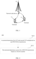
- FIG. 1 is a schematic diagram of a wireless communication system to which an embodiment of this application is applicable.
- the wireless communication system includes a terminal 11 and a network-side device 12.
- the terminal 11 may also be referred to as a terminal device or user equipment (User Equipment, UE).
- UE User Equipment
- the terminal 11 may be a terminal-side device, such as a mobile phone, a tablet personal computer (Tablet Personal Computer), a laptop computer (Laptop Computer) or notebook computer, a personal digital assistant (Personal Digital Assistant, PDA), a palmtop computer, a netbook, an ultra-mobile personal computer (ultra-mobile personal computer, UMPC), a mobile internet device (Mobile Internet Device, MID), a wearable device (Wearable Device), vehicular user equipment (VUE), or pedestrian user equipment (PUE).
- the wearable device includes a smart watch, a wrist band, earphones, glasses, and the like. It should be noted that a specific type of the terminal 11 is not limited in the embodiments of this application.
- the network-side device 12 may be a base station or a core network.
- the base station may be referred to as a NodeB, an evolved NodeB, an access point, a base transceiver station (Base Transceiver Station, BTS), a radio base station, a radio transceiver, a basic service set (Basic Service Set, BSS), an extended service set (Extended Service Set, ESS), a Node B, an evolved node B (eNB), a home NodeB, a home evolved NodeB, a WLAN access point, a Wi-Fi node, a transmission reception point (Transmitting Receiving Point, TRP), or other appropriate terms in the art.
- the base station is not limited to any specific technical term. It should be noted that in the embodiments of this application, only the base station in the NR system is used as an example, but the specific type of the base station is not limited.
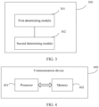
- FIG. 2 is a schematic flowchart of a method for controlling a power for a PUCCH transmission according to an embodiment of this application.
- the method 200 may be performed by a terminal.
- the method may be performed by software or hardware installed on the terminal.
- the method may include the following steps.
- the terminal determines first UCI and second UCI multiplexed on one PUCCH for transmission.
- a priority of the first UCI is a first priority
- a priority of the second UCI is a second priority
- the first priority is higher than the second priority.
- the first UCI is high-priority UCI
- the second UCI is low-priority UCI.
- the priority can be represented by a priority index.
- a priority index corresponding to the first priority is 1, and a priority index corresponding to the second priority (or a low priority) is 0.
- Different priorities may also be represented by different priority indexes.
- the first UCI and the second UCI need to be multiplexed on a PUCCH for transmission.
- the terminal determines a power for a PUCCH transmission based on a first bit number, where the first bit number is determined based on a bit number of the first UCI and/or a bit number of the second UCI.
- the terminal may determine a PUCCH transmission power adjustment factor for the PUCCH based on the first bit number and then determine the power for the PUCCH transmission based on the PUCCH transmission power adjustment factor.
- the terminal may first determine a PUCCH transmission power adjustment factor ⁇ TF,b,f,c ( i )on BWP b of a carrier f of a PUCCH cell c (for example, a primary cell PCell, a primary secondary cell PScell, and a PUCCH secondary cell SCell) and then determines the power for the PUCCH transmission based on the PUCCH transmission power adjustment factor ⁇ TF,b,f , c ( i ).
- a PUCCH transmission power adjustment factor ⁇ TF,b,f,c ( i )on BWP b of a carrier f of a PUCCH cell c for example, a primary cell PCell, a primary secondary cell PScell, and a PUCCH secondary cell SCell
- PUCCH formats correspond to different channel structures, different numbers of bits of UCI allowed to be carried, and the like.
- PUCCH format 0 and PUCCH format 1 can carry only 1 or 2 bits of UCI, while PUCCH format 2, PUCCH format 3, and PUCCH format 4 carry more than 2 bits of UCI. Therefore, in this embodiment of this application, different PUCCH transmission power adjustment factor determination methods are provided for different PUCCH formats.
- a format of the PUCCH includes one of the following: PUCCH format 2, PUCCH format 3, and PUCCH format 4.
- n HARQ-ACK ( i ) is a second bit number, where the second bit number is determined based on a bit number of first HARQ-ACK of the first priority transmitted over the PUCCH and/or a bit number of second HARQ-ACK of the second priority transmitted over the PUCCH, to be specific, the second bit number is determined based on a bit number of a high-priority first HARQ-ACK and/or a bit number of a low-priority second HARQ-ACK transmitted over the PUCCH.
- the second bit number n HARQ-ACK (i) can be determined in the following manner: ⁇ 1 ⁇ n HARQ ⁇ ACK HP + ⁇ 1 ⁇ n HARQ ⁇ ACK LP where n HARQ ⁇ ACK HP is the bit number of the first HARQ-ACK, n HARQ ⁇ ACK LP is the bit number of the second HARQ-ACK, 0 ⁇ 1 ⁇ 1, and 0 ⁇ 1 ⁇ 1.
- values of ⁇ 1 and ⁇ 1 may be set based on specific application, which are not specifically limited in this embodiment of this application.
- the bit number n HARQ ⁇ ACK HP of the first HARQ-ACK may be determined in the following manner.
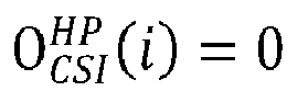
- n HARQ ⁇ ACK HP is 0 provided that no first HARQ-ACK is transmitted over the PUCCH.
- HARQ-ACK-Codebook pdsch-HARQ-ACK-Codebook-r 16
- n HARQ ⁇ ACK HP is the bit number of the first HARQ-ACK determined in a predetermined manner.
- a bit number of the HP HARQ-ACK may be determined in a corresponding manner.
- the bit number n HARQ ⁇ ACK LP of the second HARQ-ACK may be determined in the following manner.
- n HARQ ⁇ ACK LP is the bit number of the second HARQ-ACK determined in a predetermined manner.
- a bit number of the LP HARQ-ACK may be determined in a corresponding manner.
- O SR ( i ) is a third bit number, where the third bit number is determined based on a bit number of a first scheduling request (Scheduling Request, SR) of the first priority transmitted over the PUCCH and/or a bit number of a second SR of the second priority transmitted over the PUCCH.
- SR scheduling request
- the third bit number is determined based on the bit number of the high-priority first SR and/or low-priority second SR transmitted over the PUCCH.
- O SR ( i ) may be ⁇ 3 ⁇ n SR HP + ⁇ 3 ⁇ n SR LP
- n SR HP is the bit number of the first SR of the first priority
- n SR LP is the bit number of the second SR of the second priority, 0 ⁇ 3 ⁇ 1, and 0 ⁇ 3 ⁇ 1.
- values of ⁇ 3 and ⁇ 3 may be respectively the same as or different from ⁇ 1 and ⁇ 1 in the formula (2). This is not specifically limited in this embodiment of this application.
- O CSI ( i ) is a fourth bit number, where the fourth bit number is determined based on a bit number of first channel state information (Channel State Information, CSI) of the first priority transmitted over the PUCCH and/or a bit number of second CSI of the second priority transmitted over the PUCCH.
- CSI Channel State Information
- the fourth bit number is determined based on the high-priority first CSI and/or low-priority second CSI transmitted over the PUCCH.
- the fourth bit number O CSI ( i ) may be: ⁇ 4 ⁇ n CSI HP + ⁇ 4 ⁇ n CSI LP
- n CSI HP is the bit number of the first CSI of the first priority
- n CSI LP is the bit number of the second CSI of the second priority
- 0 ⁇ 4 ⁇ 1 is the bit number of the second CSI of the second priority
- values of ⁇ 4 and ⁇ 4 may be respectively the same as or different from ⁇ 1 and ⁇ 1 in the formula (2). This is not specifically limited in this embodiment of this application.
- N RE ( i ) is the number of first REs, where the number of first REs is determined based on the number of resource elements (Resource Element, RE) occupied by the first UCI and/or the number of REs occupied by the second UCI.
- N RE (i) is the number of REs occupied by the HP UCI carried on the PUCCH, the number of REs occupied by the LP UCI carried on the PUCCH, or a total number of REs occupied by the HP UCI and the LP UCI.
- N RE i M RB , b , f , c PUCCH i .
- DMRS Demodulation Reference Signal
- N sc RB represents the number of sub-carriers in each RB, for example, 12.
- N symb ⁇ UCI , b , f , c PUCCH i represents the number of OFDM symbols in the PUCCH or the number of symbols other than symbols used by DMRS.
- N symb ⁇ UCI , b , f , c PUCCH i is equal to the number of symbols occupied by the PUCCH format 2; and for PUCCH format 3, N symb ⁇ UCI , b , f , c PUCCH i is equal to the number of symbols occupied by PUCCH format 3 minus the number of the symbols other than the symbols occupied by DMRS, that is, the number of symbols occupied by the UCI.
- the number of first REs N RE (i) may be a weighted value of the number of REs occupied by the first UCI and the number of REs occupied by the second UCI, for example, ⁇ 5 ⁇ N RE HP i + ⁇ 5 ⁇ N RE LP i , where N RE HP i is the number of REs occupied by the first UCI, N RE HLP i is the number of REs occupied by the second UCI, 0 ⁇ 5 ⁇ 1, and 0 ⁇ 5 ⁇ 1. Values of ⁇ 5 and ⁇ 5 may be respectively the same as or different from ⁇ 1 and ⁇ 1 in the formula (2).
- BPRE i O ACK i + O SR i + O CSI i + O CRC i / N RE i .
- O ACK ( i ) is a second bit number, where the second bit number is determined based on a bit number of first HARQ-ACK of the first priority transmitted over the PUCCH and/or a bit number of second HARQ-ACK of the second priority transmitted over the PUCCH, and may be specifically determined with reference to the determination manner of the second bit number n HARQ-ACK ( i ) in the formula (1).
- O SR ( i ) is a third bit number, where the third bit number is determined based on a bit number of first SR of the first priority transmitted over the PUCCH and/or a bit number of second SR of the second priority transmitted over the PUCCH, and may be specifically determined with reference to the determination manner of the third bit number O SR ( i ) in the formula (1).
- O CSI ( i ) is a fourth bit number, where the fourth bit number is determined based on a bit number of first channel state information CSI of the first priority transmitted over the PUCCH and/or a bit number of second CSI of the second priority transmitted over the PUCCH, and may be specifically determined with reference to the determination manner of the fourth bit number O CSI ( i ) in the formula (1).
- O CRC ( i ) is a fifth bit number, where the fifth bit number is determined based on a bit number of first cyclic redundancy check (Cyclic redundancy check, CRC) of the first priority transmitted over the PUCCH and/or a bit number of second CRC of the second priority transmitted over the PUCCH.
- CRC Cyclic redundancy check
- the fifth bit number O CRC ( i ) may be: ⁇ 2 ⁇ n CRC HP + ⁇ 2 ⁇ n CRC LP
- n CRC HP is the bit number of the first CRC
- n CRC LP is the bit number of the second CRC, 0 ⁇ 2 ⁇ 1, and 0 ⁇ 2 ⁇ 1.
- values of ⁇ 2 and ⁇ 2 may be respectively the same as or different from ⁇ 1 and ⁇ 1 in the formula (2). This is not specifically limited in this embodiment of this application.
- N RE ( i ) is the number of first REs, where the number of first REs is determined based on the number of REs occupied by the first UCI and/or the number of REs occupied by the second UCI.
- N SC , ctrl RB i ⁇ N symb ⁇ UCI , b , f , c PUCCH i where M RB , b , f , c PUCCH i is a PUCCH transmission bandwidth, N SC , ctrl RB i is the number of sub-carriers other than sub-carriers occupied by a demodulation reference signal (Demodulation Reference Signal, DMRS) in each RB, and N symb ⁇ UCI , b , f , c PUCCH i is the number of symbols other than symbols used by the DMRS in the PUCCH.
- DMRS Demodulation Reference Signal
- N RE ( i ) represents the number of weighted (or effective) REs occupied by the UCI, for example, ⁇ 5 ⁇ N RE HP i + ⁇ 5 ⁇ N RE LP i , where N RE HP i is the number of REs occupied by the first UCI, N RE LP i is the number of REs occupied by the second UCI, 0 ⁇ 5 ⁇ 1, and 0 ⁇ 5 ⁇ 1.
- the format of the PUCCH includes one of the following: PUCCH format 0 and PUCCH format 1.
- N symb PUCCH i is the number of symbols transmitted over the PUCCH.
- N ref PUCCH Third predetermined value
- N ref PUCCH N symb slot
- N symb slot is the number of symbols in one slot
- the first bit number may be: ⁇ 6 ⁇ n UCI HP + ⁇ 6 ⁇ n UCI LP , where n UCI HP is the bit number of the first UCI, n UCI LP is the bit number of the second UCI, 0 ⁇ 6 ⁇ 1, and 0 ⁇ 6 ⁇ 1.
- values of ⁇ 6 and ⁇ 6 may be set based on specific application, which are not specifically limited in this embodiment of this application.
- ⁇ 1 to ⁇ 6 may be the same or different, ⁇ 1 to ⁇ 6 may be the same or different, and ⁇ 1 to ⁇ 6 and ⁇ 1 to ⁇ 6 may be prescribed by a protocol, configured by a higher layer parameter, indicated by the DCI, or determined based on a pre-definition rule, for example, determined based on code rates of the HP UCI and the LP UCI.
- the power for the PUCCH transmission can be determined based on the PUCCH transmission power adjustment factor ⁇ TF,b,f,c ( i ) .
- this PUCCH carries O LP-ACK LP HARQ-ACK information bits, with O CRC LP ⁇ ACK CRC bits, and O HP-ACK HP HARQ-ACK information bits, with O CRC LP ⁇ ACK CRC bits.
- the UE can determine that the transmission power of an i-th transmission occasion of this PUCCH (on BWP b of a carrier f of a cell c of this PUCCH) is P PUCCH,b,f,c ( i, q u , q d , l ) dBm.
- P PUCCH , b , f , c i q u q d l ⁇ P CMAX , f , c i P O ⁇ PUCCH , b , f , c q u + 10 log 10 2 ⁇ ⁇ M RB , b , f , c PUCCH i + PL b , f , c q d + ⁇ F ⁇ PUCCH F + ⁇ TF , b , f , c i + g b , f , c i l , where
- ⁇ TF,b,f,c () may be determined in the following manners.
- the power for the PUCCH transmission is determined based on the bit number of the LP UCI and/or the HP UCI, improving the effectiveness of the communication system.
- the method for controlling a power for a PUCCH transmission may be performed by an apparatus for controlling a power for a PUCCH transmission or a control module for performing the method for controlling a power for a PUCCH transmission in the apparatus for controlling a power for a PUCCH transmission.
- a method for controlling a power for a PUCCH transmission being performed by an apparatus for controlling a power for a PUCCH transmission is used as an example for describing the apparatus for controlling a power for a PUCCH transmission provided in the embodiments of this application.
- FIG. 3 is a schematic structural diagram of an apparatus for controlling a power for a PUCCH transmission according to an embodiment of this application. As shown in FIG. 3 , the apparatus 300 mainly included a first determining module 301 and a second determining module 302.
- the first determining module 301 is configured to determine first UCI and second UCI multiplexed on one PUCCH for transmission, where a priority of the first UCI is a first priority, a priority of the second UCI is a second priority, and the first priority is higher than the second priority; and the second determining module 302 is configured to determine a power for the PUCCH transmission based on a first bit number, where the first bit number is determined based on a bit number of the first UCI and/or a bit number of the second UCI.
- the determining, by the second determining module 302, a power for the PUCCH transmission based on a first bit number includes:
- a format of the PUCCH includes one of the following: PUCCH format 2, PUCCH format 3, and PUCCH format 4.
- the determining, by the second determining module 302, a PUCCH transmission power adjustment factor based on the first bit number includes:
- the second bit number n HARQ-ACK ( i ) is determined in the following manner: ⁇ 1 ⁇ n HARQ ⁇ ACK HP + ⁇ 1 ⁇ n HARQ ⁇ ACK LP , where n HARQ ⁇ ACK HP is the bit number of the first HARQ-ACK, n HARQ ⁇ ACK LP is the bit number of the second HARQ-ACK, 0 ⁇ 1 ⁇ 1, and 0 ⁇ 1 ⁇ 1.
- bit number n HARQ ⁇ ACK HP of the first HARQ-ACK is determined in the following manner:
- bit number n HARQ ⁇ ACK LP of the second HARQ-ACK is determined in the following manner:
- the determining, by the second determining module 302, a PUCCH transmission power adjustment factor for the PUCCH based on the first bit number includes:
- the fifth bit number O CRC ( i ) is: ⁇ 2 ⁇ n CRC HP + ⁇ 2 ⁇ n CRC LP , where n CRC HP is the bit number of the first CRC, n CRC LP is the bit number of the second CRC, 0 ⁇ 2 ⁇ 1, and 0 ⁇ 2 ⁇ 1.
- the third bit number O SR ( i ) is: ⁇ 3 ⁇ n SR HP + ⁇ 3 ⁇ n SR LP , where n SR HP is the bit number of the first SR of the first priority, n SR LP is the bit number of the second SR of the second priority, 0 ⁇ 3 ⁇ 1, and 0 ⁇ 3 ⁇ 1.
- the fourth bit number O CSI ( i ) is: ⁇ 4 ⁇ n CSI HP + ⁇ 4 ⁇ n CSI LP , where n CSI HP is the bit number of the first CSI of the first priority, n CSI LP is the bit number of the second CSI of the second priority, 0 ⁇ 4 ⁇ 1, and 0 ⁇ 4 ⁇ 1.
- N RE ( i ) is: ⁇ 5 ⁇ N RE HP i + ⁇ 5 ⁇ N RE LP i , where N RE HP i is the number of REs occupied by the first UCI, N RE HP i is the number of REs occupied by the second UCI, 0 ⁇ 5 ⁇ 1, and 0 ⁇ 5 ⁇ 1.
- the format of the PUCCH includes one of the following: PUCCH format 0 and PUCCH format 1.
- the first bit number is: ⁇ 6 ⁇ n UCI HP + ⁇ 6 ⁇ n UCI LP , where n UCI HP is the bit number of the first UCI, n UCI LP is the bit number of the second UCI, 0 ⁇ 6 ⁇ 1, and 0 ⁇ 6 ⁇ 1.
- the second determining module determines the power for the PUCCH transmission based on the bit number of the LP UCI and/or the HP UCI, improving the effectiveness of the communication system.
- the apparatus for controlling a power for a PUCCH transmission in this embodiment of this application may be an apparatus, or may be a component, an integrated circuit, or a chip in a terminal.
- the apparatus may be a mobile terminal or a non-mobile terminal.
- the mobile terminal may include but is not limited to the types of the terminal 11 listed above, and the non-mobile terminal may be a server, a network attached storage (Network Attached Storage, NAS), a personal computer (personal computer, PC), a television (Television, TV), a teller machine, a self-service machine, and the like, which are not specifically limited in this embodiment of this application.
- Network Attached Storage Network Attached Storage
- PC personal computer
- TV television
- teller machine teller machine
- self-service machine a self-service machine
- the apparatus for controlling a power for a PUCCH transmission in this embodiment of this application may be an apparatus with an operating system.
- the operating system may be an android (Android) operating system, may be an iOS operating system, or may be another possible operating system. This is not specifically limited in this embodiment of this application.
- the apparatus for controlling a power for a PUCCH transmission provided in this embodiment of this application can implement the processes implemented in the method embodiment in FIG. 2 , with the same technical effects achieved. To avoid repetition, details are not described herein again.
- an embodiment of this application further provides a communication device 400 including a processor 401, a memory 402, and a program or instructions stored in the memory 402 and capable of running on the processor 401.
- a communication device 400 including a processor 401, a memory 402, and a program or instructions stored in the memory 402 and capable of running on the processor 401.
- the communication device 400 is a terminal and when the program or instructions are executed by the processor 401, the processes of the foregoing embodiments of the method for controlling a power for a PUCCH transmission are implemented, with the same technical effects achieved.
- the communication device 400 is a network-side device and when the program or instructions are executed by the processor 401, the processes of the foregoing embodiments of the method for controlling a power for a PUCCH transmission are implemented, with the same technical effects achieved. To avoid repetition, details are not described herein again.
- An embodiment of this application further provides a terminal including a processor and a communication interface, where the processor is applied to the processes of the foregoing embodiments of the method for controlling a power for a PUCCH transmission, and the communication interface is configured to communicate with other communication devices, for example, to communicate with other terminals or network-side devices.
- This terminal embodiment corresponds to the foregoing method embodiments on the terminal side. All implementation processes and implementation manners in the foregoing method embodiments may be applicable to this terminal embodiment, with the same technical effects achieved.
- FIG. 5 is a schematic diagram of a hardware structure of a terminal for implementing the embodiments of this application.
- the terminal 500 includes but is not limited to components such as a radio frequency unit 501, a network module 502, an audio output unit 503, an input unit 504, a sensor 505, a display unit 506, a user input unit 507, an interface unit 508, a memory 509, and a processor 510.
- components such as a radio frequency unit 501, a network module 502, an audio output unit 503, an input unit 504, a sensor 505, a display unit 506, a user input unit 507, an interface unit 508, a memory 509, and a processor 510.
- the terminal 500 may further include a power supply (for example, a battery) supplying power to the components.
- the power supply may be logically connected to the processor 510 via a power management system, so that functions such as charge management, discharge management, and power consumption management are implemented by using the power management system.
- the structure of the terminal shown in FIG. 5 does not constitute any limitation on the terminal, and the terminal may include more or fewer components than shown in the figure, or combine some of the components, or have different arrangements of the components. Details are not described herein.
- the input unit 504 may include a graphics processing unit (Graphics Processing Unit, GPU) 5041 and a microphone 5042.
- the graphics processing unit 5041 processes image data of a static picture or a video that is obtained by an image capture apparatus (for example, a camera) in a video capture mode or an image capture mode.
- the display unit 506 may include a display panel 5061.
- the display panel 5061 may be configured in a form of a liquid crystal display, an organic light-emitting diode display, or the like.
- the user input unit 507 includes a touch panel 5071 and other input devices 5072.
- the touch panel 5071 is also referred to as a touchscreen.
- the touch panel 5071 may include two parts: a touch detection apparatus and a touch controller.
- the other input devices 5072 may include but are not limited to a physical keyboard, a function button (for example, a volume control button or a power on/off button), a trackball, a mouse, and a joystick. Details are not described herein again.
- the radio frequency unit 501 sends downlink data received from a network-side device to the processor 510 for processing, and in addition, sends uplink data to the network-side device.
- the radio frequency unit 501 includes but is not limited to an antenna, at least one amplifier, a transceiver, a coupler, a low noise amplifier, a duplexer, and the like.
- the memory 509 may be configured to store software programs or instructions and various data.
- the memory 509 may include a program or instruction storage area and a data storage area.
- the program or instruction storage area may store an operating system, an application program or instruction required by at least one function (for example, a sound playback function or an image playback function), and the like.
- the memory 509 may include a high-speed random access memory, and may further include a non-volatile memory, where the non-transitory memory may be a read-only memory (Read-Only Memory, ROM), a programmable read-only memory (Programmable ROM, PROM), an erasable programmable read-only memory (Erasable PROM, EPROM), an electrically erasable programmable read-only memory (Electrically EPROM, EEPROM), or a flash memory.
- ROM Read-Only Memory
- PROM programmable read-only memory
- Erasable PROM Erasable PROM
- EPROM electrically erasable programmable read-only memory
- EEPROM electrically erasable programmable read-only memory
- flash memory for example, at least one disk storage device, flash memory device, or another non-transitory solid-state storage device.
- the processor 510 may include one or more processing units.
- the processor 510 may integrate an application processor and a modem processor.
- the application processor mainly processes an operating system, a user interface, an application program, instructions, or the like.
- the modem processor mainly processes wireless communication, for example, being a baseband processor. It can be understood that the modem processor may alternatively be not integrated in the processor 510.
- the processor 510 is configured to determine first UCI and second UCI multiplexed on one PUCCH for transmission, where a priority of the first UCI is a first priority, a priority of the second UCI is a second priority, and the first priority is higher than the second priority; and determine a power for a PUCCH transmission based on a first bit number, where the first bit number is determined based on a bit number of the first UCI and/or a bit number of the second UCI.
- the determining a power for a PUCCH transmission based on a first bit number includes:
- a format of the PUCCH includes one of the following: PUCCH format 2, PUCCH format 3, and PUCCH format 4.
- the determining a PUCCH transmission power adjustment factor based on the first bit number includes:
- the second bit number n HARQ-ACK ( i ) is determined in the following manner: ⁇ 1 ⁇ n HARQ ⁇ ACK HP + ⁇ 1 ⁇ n HARQ ⁇ ACK LP , where n HARQ ⁇ ACK HP is the bit number of the first HARQ-ACK, n HARQ ⁇ ACK LP is the bit number of the second HARQ-ACK, 0 ⁇ 1 ⁇ 1, and 0 ⁇ 1 ⁇ 1.
- the determining a PUCCH transmission power adjustment factor based on the first bit number includes:
- An embodiment of this application further provides a readable storage medium, where a program or instructions are stored in the readable storage medium.
- a program or instructions are stored in the readable storage medium.
- the processes of the foregoing embodiments of the method for controlling a power for a PUCCH transmission can be implemented, with the same technical effects achieved. To avoid repetition, details are not described herein again.
- the processor is a processor in the terminal described in the foregoing embodiments.
- the readable storage medium includes a computer-readable storage medium, such as a computer read-only memory (Read-Only Memory, ROM), a random access memory (Random Access Memory, RAM), a magnetic disk, or an optical disc.
- An embodiment of this application further provides a chip.
- the chip includes a processor and a communication interface, where the communication interface is coupled to the processor, and the processor is configured to run a program or instructions to implement the processes of the foregoing embodiments of the method for controlling a power for a PUCCH transmission, with the same technical effects achieved. To avoid repetition, details are not described herein again.
- the chip mentioned in this embodiment of this application may also be referred to as a system-level chip, a system chip, a chip system, a system-on-chip, or the like.
- An embodiment of this application further provides a computer program/program product, where the computer program/program product is stored in a non-transitory storage medium.
- the program/program product is executed by at least one processor, the processes of the foregoing embodiments of the method for controlling a power for a PUCCH transmission are implemented, with the same technical effects achieved. To avoid repetition, details are not described herein again.
- the computer software product is stored in a storage medium (for example, a ROM/RAM, a magnetic disk, or an optical disc), and includes several instructions for instructing a terminal (which may be a mobile phone, a computer, a server, an air conditioner, a network device, or the like) to perform the methods described in the embodiments of this application.
- a storage medium for example, a ROM/RAM, a magnetic disk, or an optical disc
- a terminal which may be a mobile phone, a computer, a server, an air conditioner, a network device, or the like
Landscapes
- Engineering & Computer Science (AREA)
- Signal Processing (AREA)
- Computer Networks & Wireless Communication (AREA)
- Mobile Radio Communication Systems (AREA)
Abstract
Description
- This application claims priority to
Chinese Patent Application No. 202111130451.3, filed with the China National Intellectual Property Administration on September 26, 2021 - This application pertains to the field of wireless communication technologies, and specifically relates to a method and an apparatus for controlling a power for a physical uplink control channel (Physical Uplink Control Channel, PUCCH) transmission and a terminal.
- In a new radio (New Radio, NR) system, one piece of user equipment (User Equipment, UE) may support different services, and different services have different service requirements, for example, requirements on delay and reliability. Therefore, a mechanism for marking a priority of a physical uplink control channel (Physical Uplink Control Channel, PUCCH) and/or a physical uplink shared channel (Physical Uplink Shared Channel, PUSCH) is introduced. Specifically, two levels of physical layer priorities are introduced: a high priority and a low priority.
- Uplink control information (Uplink Control Information, UCI) is transmitted over a physical uplink control channel (PUCCH). Due to reasons such as start symbol and symbol length, time overlap may occur between different PUCCHs. When PUCCH time-domain resources of different priorities overlap, simply discarding a low-priority PUCCH has a significant impact on the performance of low-priority service transmissions. Therefore, to mitigate the impact on low-priority transmissions, communication systems are required to support multiplexing between PUCCHs of different priorities. For example, when a PUCCH time-domain resource carrying high-priority (High priority, HP) hybrid automatic repeat request acknowledgement (Hybrid automatic repeat request acknowledgement, HARQ-ACK) overlaps a PUCCH time-domain resource carrying low-priority (Low priority, LP) HARQ-ACK and specified conditions are met, user equipment (User Equipment, UE) multiplexes HP HARQ-ACK and LP HARQ-ACK on one PUCCH for transmission. HP HARQ-ACK and LP HARQ-ACK have different requirements on reliability and therefore correspond to different transmission code rates. To be specific, separate coding is required. Similarly, multiplexing of UCIs of different priorities also needs specified timeline requirements to be met.
- However, only channels of a same priority can be multiplexed, with one PUCCH resource carrying UCIs of one priority. While performing PUCCH transmission power control, the UE needs to determine a power for the PUCCH transmission based on bits per resource element (Bit Per Resource Element, BPRE). The UE determines the BPRE based on a bit number of to-be-transmitted UCI and the number of resource elements (Resource Element, RE). In the prior art, one PUCCH carries only one BPR. When UCIs of different priorities (for example, LP HARQ-ACK and HP HARQ-ACK) are multiplexed on one PUCCH resource, two code rates may be configured for one PUCCH format, one for low-priority UCI and the other for high-priority UCI. In this case, there is no effective solution yet for the problem of how transmission power of the PUCCH multiplexed with UCIs of different priorities is determined.
- Embodiments of this application provide a method and an apparatus for controlling a power for a PUCCH transmission and a terminal, so as to solve the problem of how transmission power of PUCCH multiplexed with UCIs of different priorities is determined.
- According to a first aspect, a method for controlling a power for a PUCCH transmission is provided, including: determining, by a terminal, first UCI and second UCI multiplexed on one PUCCH for transmission, where a priority of the first UCI is a first priority, a priority of the second UCI is a second priority, and the first priority is higher than the second priority; and determining, by the terminal, a power for the PUCCH transmission based on a first bit number, where the first bit number is determined based on a bit number of the first UCI and/or a bit number of the second UCI.
- According to a second aspect, an apparatus for controlling a power for a PUCCH transmission is provided, including: a first determining module configured to determine first UCI and second UCI multiplexed on one PUCCH for transmission, where a priority of the first UCI is a first priority, a priority of the second UCI is a second priority, and the first priority is higher than the second priority; and a second determining module configured to determine a power for the PUCCH transmission based on a first bit number, where the first bit number is determined based on a bit number of the first UCI and/or a bit number of the second UCI.
- According to a third aspect, a terminal is provided. The terminal includes a processor, a memory, and a program or instructions stored in the memory and capable of running on the processor, and when the program or instructions are executed by the processor, the steps of the method according to the first aspect are implemented.
- According to a fourth aspect, a terminal is provided, including a processor and a communication interface, where the processor is configured to perform the steps of the method according to the first aspect, and the communication interface is configured to communicate with other communication devices.
- According to a fifth aspect, a readable storage medium is provided. A program or instructions are stored in the readable storage medium, and when the program or instructions are executed by a processor, the steps of the method according to the first aspect are implemented.
- According to a sixth aspect, a chip is provided. The chip includes a processor and a communication interface, where the communication interface is coupled to the processor, and the processor is configured to run a program or instructions to implement the steps of the method according to the first aspect.
- According to a seventh aspect, a computer program/program product is provided. The computer program/program product is stored in a non-transient storage medium, and the program/program product is executed by at least one processor to implement the steps of the method according to the first aspect.
- In the embodiments of this application, the terminal determines the first UCI and the second UCI of different priorities that are multiplexed on one PUCCH for transmission and determines the power for the PUCCH transmission based on the bit number of the first UCI and/or the second UCI, thereby solving the problem of how transmission power of the PUCCH multiplexed with UCIs of different priorities is determined.
-
-
FIG. 1 is a schematic diagram of a wireless communication system to which an embodiment of this application is applicable; -
FIG. 2 is a schematic flowchart of a method for controlling a power for a PUCCH transmission according to an embodiment of this application; -
FIG. 3 is a schematic structural diagram of an apparatus for controlling a power for a PUCCH transmission according to an embodiment of this application; -
FIG. 4 is a schematic structural diagram of a communication device according to an embodiment of this application; and -
FIG. 5 is a schematic diagram of a hardware structure of a terminal according to an embodiment of this application. - The following clearly describes the technical solutions in the embodiments of this application with reference to the accompanying drawings in the embodiments of this application. Apparently, the described embodiments are merely some rather than all of the embodiments of this application. All other embodiments obtained by persons of ordinary skill in the art based on the embodiments of this application shall fall within the protection scope of this application.
- The terms "first", "second", and the like in the specification and claims of this application are used to distinguish between similar objects rather than to describe a specific order or sequence. It should be understood that terms used in this way are interchangeable in appropriate circumstances so that the embodiments of this application can be implemented in other orders than the order illustrated or described herein. In addition, "first" and "second" are usually used to distinguish between objects of a same type and do not limit the quantity of objects. For example, there may be one or more first objects. In addition, "and/or" in the specification and claims represents at least one of connected objects, and the character "/" generally indicates that the contextually associated objects have an "or" relationship.
- It is worth noting that the technology described in the embodiments of this application is not limited to long term evolution (Long Term Evolution, LTE)/LTE-Advanced (LTE-Advanced, LTE-A) systems, but may also be used in other wireless communication systems such as code division multiple access (Code Division Multiple Access, CDMA), time division multiple access (Time Division Multiple Access, TDMA), frequency division multiple access (Frequency Division Multiple Access, FDMA), orthogonal frequency division multiple access (Orthogonal Frequency Division Multiple Access, OFDMA), single-carrier frequency division multiple access (Single-carrier Frequency-Division Multiple Access, SC-FDMA), and other systems. The terms "system" and "network" in the embodiments of this application are often used interchangeably, and the technology described herein may be used in the above-mentioned systems and radio technologies as well as other systems and radio technologies. However, in the following descriptions, a new radio (New Radio, NR) system is described for illustration purposes, NR terms are used in most of the following descriptions, and these technologies may also be applied to other applications than the NR system application, for example, the 6th generation (6th Generation, 6G) communication system.
-
FIG. 1 is a schematic diagram of a wireless communication system to which an embodiment of this application is applicable. The wireless communication system includes aterminal 11 and a network-side device 12. Theterminal 11 may also be referred to as a terminal device or user equipment (User Equipment, UE). Theterminal 11 may be a terminal-side device, such as a mobile phone, a tablet personal computer (Tablet Personal Computer), a laptop computer (Laptop Computer) or notebook computer, a personal digital assistant (Personal Digital Assistant, PDA), a palmtop computer, a netbook, an ultra-mobile personal computer (ultra-mobile personal computer, UMPC), a mobile internet device (Mobile Internet Device, MID), a wearable device (Wearable Device), vehicular user equipment (VUE), or pedestrian user equipment (PUE). The wearable device includes a smart watch, a wrist band, earphones, glasses, and the like. It should be noted that a specific type of theterminal 11 is not limited in the embodiments of this application. The network-side device 12 may be a base station or a core network. The base station may be referred to as a NodeB, an evolved NodeB, an access point, a base transceiver station (Base Transceiver Station, BTS), a radio base station, a radio transceiver, a basic service set (Basic Service Set, BSS), an extended service set (Extended Service Set, ESS), a Node B, an evolved node B (eNB), a home NodeB, a home evolved NodeB, a WLAN access point, a Wi-Fi node, a transmission reception point (Transmitting Receiving Point, TRP), or other appropriate terms in the art. Provided that the same technical effects are achieved, the base station is not limited to any specific technical term. It should be noted that in the embodiments of this application, only the base station in the NR system is used as an example, but the specific type of the base station is not limited. - The following describes in detail the methods for controlling a power for a PUCCH transmission provided in the embodiments of this application by using some embodiments and application scenarios thereof with reference to the accompanying drawings.
-
FIG. 2 is a schematic flowchart of a method for controlling a power for a PUCCH transmission according to an embodiment of this application. Themethod 200 may be performed by a terminal. In other words, the method may be performed by software or hardware installed on the terminal. As shown inFIG. 2 , the method may include the following steps. - S210. The terminal determines first UCI and second UCI multiplexed on one PUCCH for transmission.
- A priority of the first UCI is a first priority, a priority of the second UCI is a second priority, and the first priority is higher than the second priority. In other words, the first UCI is high-priority UCI, and the second UCI is low-priority UCI.
- In this embodiment of this application, the priority can be represented by a priority index. For example, a priority index corresponding to the first priority (or a high priority) is 1, and a priority index corresponding to the second priority (or a low priority) is 0. Different priorities may also be represented by different priority indexes.
- For example, in a case that there is a conflict between transmission resources of a PUCCH for transmitting the first UCI and a PUCCH for transmitting the first UCI, the first UCI and the second UCI need to be multiplexed on a PUCCH for transmission.
- S220. The terminal determines a power for a PUCCH transmission based on a first bit number, where the first bit number is determined based on a bit number of the first UCI and/or a bit number of the second UCI.
- In a possible implementation, in S220, the terminal may determine a PUCCH transmission power adjustment factor for the PUCCH based on the first bit number and then determine the power for the PUCCH transmission based on the PUCCH transmission power adjustment factor.
- For example, the terminal may first determine a PUCCH transmission power adjustment factor ΔTF,b,f,c (i)on BWP b of a carrier f of a PUCCH cell c (for example, a primary cell PCell, a primary secondary cell PScell, and a PUCCH secondary cell SCell) and then determines the power for the PUCCH transmission based on the PUCCH transmission power adjustment factor Δ TF,b,f,c (i).
- Different PUCCH formats correspond to different channel structures, different numbers of bits of UCI allowed to be carried, and the like. For example, PUCCH format 0 and PUCCH format 1 can carry only 1 or 2 bits of UCI, while PUCCH format 2, PUCCH format 3, and PUCCH format 4 carry more than 2 bits of UCI. Therefore, in this embodiment of this application, different PUCCH transmission power adjustment factor determination methods are provided for different PUCCH formats.
- In a possible implementation, a format of the PUCCH includes one of the following: PUCCH format 2, PUCCH format 3, and PUCCH format 4.
- In this possible implementation, optionally, the determining, by the terminal, a PUCCH transmission power adjustment factor based on a first bit number may include: in a case that the first bit number is less than or equal to a threshold, determining, by the terminal, the PUCCH transmission power adjustment factor Δ TF,b,f,c (i)in the following manner:

in the formula (1), K1 is a first predetermined value, for example, K1=11. - In the formula (1), nHARQ-ACK (i) is a second bit number, where the second bit number is determined based on a bit number of first HARQ-ACK of the first priority transmitted over the PUCCH and/or a bit number of second HARQ-ACK of the second priority transmitted over the PUCCH, to be specific, the second bit number is determined based on a bit number of a high-priority first HARQ-ACK and/or a bit number of a low-priority second HARQ-ACK transmitted over the PUCCH.
- For example, the second bit number nHARQ-ACK(i) can be determined in the following manner:


- In specific application, the second bit number may be determined based only on the bit number of the second HARQ-ACK, that is, α1=0 and β1=1. Alternatively, the second bit number may be determined based only on the bit number of the first HARQ-ACK, that is, α1=1 and β1=0. Alternatively, a sum of bit numbers of HP HARQ-ACK and LP HARQ-ACK that are carried on the PUCCH may be used as the second bit number, that is, α1=1 and β1=1. Alternatively, values of α1 and β1 may be set based on specific application, which are not specifically limited in this embodiment of this application.
- The bit number

- (1) In a case that no HARQ-ACK codebook is configured for the HARQ-ACK of the first priority of the terminal and the first HARQ-ACK is transmitted over the PUCCH,

For example, in a case that none of pdsch-HARQ-ACK-Codebook, pdsch-HARQ-ACK-Codebook-r16, pdsch-HARQ-ACK-OneShotFeedback, and Triggering HARQ-ACKretx is configured for high-priority (High Priority, HP) HARQ-ACK of the UE, and the HP HARQ-ACK is transmitted over the PUCCH by the UE,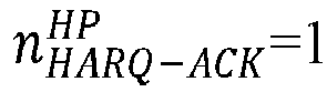
- (2) In a case that no first HARQ-ACK is transmitted over the PUCCH,

- To be specific, no matter whether a HARQ-ACK codebook is configured for the HARQ-ACK of the first priority of the terminal,

- For example, in a case that none of pdsch-HARQ-ACK-Codebook, pdsch-HARQ-ACK-Codebook-r 16, pdsch-HARQ-ACK-OneShotFeedback, and Triggering HARQ-ACKretx is configured for the HP HARQ-ACK of the UE, and no HP HARQ-ACK is transmitted over the PUCCH by the UE,
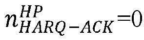
- (3) In a case that a HARQ-ACK codebook is configured for the HARQ-ACK of the first priority of the terminal and the first HARQ-ACK is transmitted over the PUCCH,

- For example, in a case that a HARQ-ACK codebook is configured for the HP HARQ-ACK of the UE and the HARQ-ACK codebook configured is a type (type)1 codebook, an (enhanced) type2 codebook, or an (enhanced) type3 codebook, a bit number of the HP HARQ-ACK may be determined in a corresponding manner.
- The bit number

- (1) In a case that no HARQ-ACK codebook is configured for the HARQ-ACK of the second priority of the terminal and the second HARQ-ACK is transmitted over the PUCCH,

For example, in a case that none of pdsch-HARQ-ACK-Codebook, pdsch-HARQ-ACK-Codebook-r16, pdsch-HARQ-ACK-OneShotFeedback, and Triggering HARQ-ACKretx is configured for low-priority (Low Priority, LP) HARQ-ACK of the UE, and the LP HARQ-ACK is transmitted over the PUCCH by the UE,
- (2) In a case that no second HARQ-ACK is transmitted over the PUCCH,


- For example, in a case that none of pdsch-HARQ-ACK-Codebook, pdsch-HARQ-ACK-Codebook-r16, pdsch-HARQ-ACK-OneShotFeedback, and Triggering HARQ-ACKretx is configured for the LP HARQ-ACK of the UE, and no LP HARQ-ACK is transmitted in the PUCCH transmission,

- (3) In a case that a HARQ-ACK codebook is configured for the HARQ-ACK of the second priority of the terminal and the second HARQ-ACK is transmitted over the PUCCH,

- For example, in a case that a HARQ-ACK codebook is configured for the LP HARQ-ACK of the UE and the HARQ-ACK codebook configured is a type (type)1 codebook, a type2 codebook, or a type3 codebook, a bit number of the LP HARQ-ACK may be determined in a corresponding manner.
- In the formula (1), OSR (i) is a third bit number, where the third bit number is determined based on a bit number of a first scheduling request (Scheduling Request, SR) of the first priority transmitted over the PUCCH and/or a bit number of a second SR of the second priority transmitted over the PUCCH. To be specific, the third bit number is determined based on the bit number of the high-priority first SR and/or low-priority second SR transmitted over the PUCCH.
- Optionally, OSR (i) may be


- In the formula (1), OCSI (i) is a fourth bit number, where the fourth bit number is determined based on a bit number of first channel state information (Channel State Information, CSI) of the first priority transmitted over the PUCCH and/or a bit number of second CSI of the second priority transmitted over the PUCCH. To be specific, the fourth bit number is determined based on the high-priority first CSI and/or low-priority second CSI transmitted over the PUCCH.
- Optionally, the fourth bit number OCSI (i) may be:


- In the formula (1), NRE (i) is the number of first REs, where the number of first REs is determined based on the number of resource elements (Resource Element, RE) occupied by the first UCI and/or the number of REs occupied by the second UCI.
- For example, NRE(i) is the number of REs occupied by the HP UCI carried on the PUCCH, the number of REs occupied by the LP UCI carried on the PUCCH, or a total number of REs occupied by the HP UCI and the LP UCI. For example,




- In a case that the format of the PUCCH is PUCCH format 2, PUCCH format 3 or PUCCH format 4, the determining, by the terminal, a PUCCH transmission power adjustment factor based on the first bit number may include: in a case that the first bit number is greater than a threshold, determining, by the terminal, the PUCCH transmission power adjustment factor ΔTF,b,f,c(i) in the following manner:

- In the formula (5),

- OACK (i) is a second bit number, where the second bit number is determined based on a bit number of first HARQ-ACK of the first priority transmitted over the PUCCH and/or a bit number of second HARQ-ACK of the second priority transmitted over the PUCCH, and may be specifically determined with reference to the determination manner of the second bit number nHARQ-ACK (i) in the formula (1).
- OSR (i) is a third bit number, where the third bit number is determined based on a bit number of first SR of the first priority transmitted over the PUCCH and/or a bit number of second SR of the second priority transmitted over the PUCCH, and may be specifically determined with reference to the determination manner of the third bit number OSR (i) in the formula (1).
- OCSI (i) is a fourth bit number, where the fourth bit number is determined based on a bit number of first channel state information CSI of the first priority transmitted over the PUCCH and/or a bit number of second CSI of the second priority transmitted over the PUCCH, and may be specifically determined with reference to the determination manner of the fourth bit number OCSI (i) in the formula (1).
- OCRC (i) is a fifth bit number, where the fifth bit number is determined based on a bit number of first cyclic redundancy check (Cyclic redundancy check, CRC) of the first priority transmitted over the PUCCH and/or a bit number of second CRC of the second priority transmitted over the PUCCH.
- For example, the fifth bit number OCRC (i) may be:


- NRE (i) is the number of first REs, where the number of first REs is determined based on the number of REs occupied by the first UCI and/or the number of REs occupied by the second UCI. For example, NRE (i) is the number of REs occupied by the HP UCI carried on the PUCCH, the number of REs occupied by the LP UCI carried on the PUCCH, or a total number of REs occupied by the HP UCI and the LP UCI, for example,





- In another possible implementation, the format of the PUCCH includes one of the following: PUCCH format 0 and PUCCH format 1.
- In this possible implementation, optionally, the terminal can determine the PUCCH transmission power adjustment factor ΔTF,b,f,c (i) in the following manner:

- In the formula (7),

- In a case that the format of the PUCCH is PUCCH format 0,


- In a case that the format of the PUCCH is PUCCH format 0, Δ UCI (i) = 0; and in a case that the format of the PUCCH is PUCCH format 1, Δ UCI (i) = 10log 10(OUCI (i)), where OUCI (i) is the first bit number, that is, OUCI (i) may be determined based on the bit number of the first UCI and/or the bit number of the second UCI.
- In this embodiment of this application, optionally, the first bit number may be:



- For example, the first bit number may be determined based only on the bit number of the second UCI, that is, α6=0 and β6=1. Alternatively, the first bit number may be determined based only on the bit number of the first UCI, that is, α6=1, and β6=0. Alternatively, a sum of bit numbers of the first UCI and the second UCI that are carried on the PUCCH may be used as the first bit number, that is, α6=1 and β6=1. Alternatively, values of α6 and β6 may be set based on specific application, which are not specifically limited in this embodiment of this application.
- In addition, in this embodiment of this application, α1 to α6 may be the same or different, β1 to β6 may be the same or different, and α1 to α6 and β1 to β6 may be prescribed by a protocol, configured by a higher layer parameter, indicated by the DCI, or determined based on a pre-definition rule, for example, determined based on code rates of the HP UCI and the LP UCI. Optionally, α1=α2=α3=α4=α5, β1-β2-β3-β4-β5, α6=1,

- After the PUCCH transmission power adjustment factor Δ TF,b,f,c (i) is determined, the power for the PUCCH transmission can be determined based on the PUCCH transmission power adjustment factor Δ TF,b,f,c (i).
- For example, if the UE transmits one PUCCH in PUCCH format 2 or PUCCH format 3, this PUCCH carries OLP-ACK LP HARQ-ACK information bits, with


- i represents a transmission time, that is, a PUCCH transmission occasion;
- qd represents a path loss calculation basis reference signal identifier;
- l represents a closed loop power control process identifier;
- PCMAX,f,c (i) represents a maximum transmission power;
- P O_PUCCH,b,f,c (qu ) is a sum of P O_NOMINAL_PUCCH and P O_UE_PUCCH(qu ), where P O_NOMINAL_PUCCH and P O_UE_PUCCH(qu ) are configured or pre-defined by a higher layer parameter;
-

- PLb,f,c (qd ) represents an estimated path loss value;
- Δ F_PUCCH(F) represents a power compensation amount associated with the format of the PUCCH;
- Δ TF,b,f,c (i) represents a power compensation amount associated with the format of the PUCCH and the bit number of the UCI, that is, the foregoing PUCCH transmission power adjustment factor; and
- gb,f,c (i, l) represents a closed loop power control adjustment amount. Closed loop power control may be a transmission power control (Transmission power Control, TPC) command in downlink control information (Downlink Control Information, DCI) for scheduling the PUCCH or a TPC command provided in DCI 2_2 scrambled with PTC-PUCCH-RNTI.
- Δ TF,b,f,c () may be determined in the following manners.
- Manner 1:
- (1) If the bit number of the HP UCI carried on the PUCCH is less than or equal to 11,

- K1=6;
- nHARQ-ACK (i) represents the bit number of HP HARQ-ACK, and for a type 1, type 2, or type 3 code book, nHARQ-ACK (i) may be the bit number of the HP HARQ-ACK determined in a specified manner; if HP HARQ-ACK of the UE is not configured with any one ofpdsch-HARQ ACK Codebook, pdsch-HARQACKCodebook-r 16, pdsch-HARQ-ACK-OneShotFeedback, and Triggering HARQ-ACKretx, nHARQ-ACK (i) = 1;
- OSR (i) represents the bit number of the HP SR carried on the PUCCH;
- OCSI (i) represents the bit number of the HP CSI carried on the PUCCH, and if no HP CSI is carried on the PUCCH, OCSI (i) = 0; and
- NRE (i) represents the number of REs occupied by the HP UCI.
- (2) If the bit number of the HP UCI carried on the PUCCH is greater than 11, Δ TF,b,f,c (i) = 10log 10(2 K2·BPRE(i) - 1), where
- K2=2.4; and
- BPRE(i) = (OACK (i) + OSR (i) + OCSI (i) + OCRC (i)/NRE (i), where OACK (i) represents the bit number of the HP HARQ-ACK, and for a type 1, type 2, or type 3 code book, OACK (i) may be the bit number of the HP HARQ-ACK determined in a specified manner, and if the HP HARQ-ACK of the UE is not configured with any one of pdsch-HARQ-ACK-Codebook, pdsch-HARQ-ACK-Codebook-r16, pdsch-HARQ-ACK-OneShotFeedback, and Triggering HARQ-ACKretx, OACK (i) = 1; OSR (i) represents the bit number of the HP SR; OCSI (i) represents the bit number of the HP CSI, and if there is no HP CSI, OCSI (i) = 0; and NRE (i) represents the number of REs occupied by the HP UCI.
- (1) If the bit number of the HP UCI carried on the PUCCH is less than or equal to 11,
- Manner 2:
- (1) If the bit number of the LP UCI carried on the PUCCH is less than or equal to 11,

- K1=6;
- nHARQ-ACK (i) represents the bit number of the LP HARQ-ACK, and for a type 1, type 2, or type 3 code book, nHARQ-ACK (i) may be the bit number of the LP HARQ-ACK determined in a specified manner; if the LP HARQ-ACK of the UE is not configured with any one of pdsch-HARQ-ACK-Codebook, pdsch-HARQ-ACK-Codebook-r16, pdsch-HARQ-ACK-OneShotFeedback, and Triggering HARQ-ACKretx, nHARQ-ACK (i) = 1;
- OSR (i) represents the bit number of the LP SR carried on the PUCCH;
- OCSI (i) represents the bit number of the LP CSI carried on the PUCCH, and if no LP CSI is carried on the PUCCH, OCSI (i) = 0; and
- NRE (i) represents the number of REs occupied by the LP UCI.
- (2) If the bit number of the LP UCI carried on the PUCCH is greater than 11, ΔTF,b,f,c (i) = 10log 10(2 K2·BPRE(i) - 1), where
- K2=2.4; and
- BPRE(i) = (OACK (i) + OSR (i) + OCSI (i) + OCRC (i)/NRE (i), where OACK (i) represents the bit number of the LP HARQ-ACK, and for a type 1, type 2, or type 3 code book, OACK (i) may be the bit number of the LP HARQ-ACK determined in a specified manner, and if the LP HARQ-ACK of the UE is not configured with any one of pdsch-HARQ ACK Codebook, pdsch-HARQ-ACK-Codebook-r16, pdsch-HARQ-ACK-OneShotFeedback, and Triggering HARQ-ACKretx, OACK (i) = 1; OSR (i) represents the bit number of the HP SR; OCSI (i) represents the bit number of the HP CSI, and if there is no LP CSI, OCSI (i) = 0; and NRE (i) represents the number of REs occupied by the LP UCI.
- (1) If the bit number of the LP UCI carried on the PUCCH is less than or equal to 11,
- Manner 3:
- (1) If a total bit number of the HP UCI and LP UCI carried on the PUCCH is less than or equal to 11, Δ TF,b,f,c () = 10log 10(K 1·(nHARQ-ACK (i) + OSR (i) + OCSI (i))/NRE (i)), where
- K1=6;
- nHARQ-ACK (i) represents a total bit number of the HP HARQ-ACK and the LP HARQ-ACK, and for a type 1, type 2, or type 3 code book, nHARQ-ACK (i) may be the total bit number of the HP HARQ-ACK and the LP HARQ-ACK determined in a specified manner; in a case that the HP HARQ-ACK of the UE is not configured with any one of pdsch-HARQ ACK Codebook, pdsch-HARQ-A CK-Codebook-r 16, pdsch-HARQ-ACK-OneShotFeedback, and Triggering HARQ-ACKretx, if the HP HARQ-ACK is multiplexed on the PUCCH,


- OSR (i) represents a total bit number of the HP SR and LP SR carried on the PUCCH;
- OCSI (i) represents a total bit number of the HP CSI and LP CSI carried on the PUCCH; and
- NRE (i) represents a total number of REs occupied by the HP UCI and the LP UCI.
- (2) If the total bit number of the HP UCL and LP UCI carried on the PUCCH is greater than 11, Δ TF,b,f,c (i) = 10log 10(2 K2·BPRE(i) - 1), where
- K2=2.4; and
- BPRE(i) = (OACK (i) + OSR (i) + OCSI (i) + OCRC (i)/NRE (i), where OACK (i) represents a total number of the HP HARQ-ACK and the LP HARQ-ACK, and for a type 1, type 2, or type 3 code book, in a case that the HP HARQ-ACK of the UE is not configured with any one of pdsch-HARQ-ACK-Codebook, pdsch-HARQ-ACK-Codebook-r16, pdsch-HARQ-ACK-OneShotFeedback, and Triggering HARQ-ACKretx, if the HP HARQ-ACK is multiplexed on the PUCCH,



- (1) If a total bit number of the HP UCI and LP UCI carried on the PUCCH is less than or equal to 11, Δ TF,b,f,c () = 10log 10(K 1·(nHARQ-ACK (i) + OSR (i) + OCSI (i))/NRE (i)), where
- Manner 4:
- (1) If the HP UCI and LP UCI carried on the PUCCH satisfies:

- K1=6;
- nHARQ-ACK (i) represents a bit number of weighted (or effective) HARQ-ACK, and


- OSR (i) represents a bit number of a weighted (or effective) SR, and OSR (i) = βHP ·


- OCSI (i) represents a bit number of weighted (or effective) CSI, and OSR (i) = γ HP ·




- NRE (i) represents the number of weighted (or effective) REs occupied by the UCI; and


- (2) If the HP UCI and the LP UCI satisfy the following formula:


- K2=2.4;
- BPRE(i) = (OACK (i) + OSR (i) + OCSI (i) + OCRC (i))/NRE(i), where
- OACK (i) represents a bit number of weighted (or effective) HARQ-ACK, and for a type 1, type 2, or type 3 code book,



- OSR (i) represents a bit number of a weighted (or effective) SR, and OSR (i) = βHP ·




- It should be noted that the foregoing α, β, αHP, αLP, βHP, βLP, γHP, γLP, δHP, and δLP are values from 0 to 1 (including 0 and 1) and may be prescribed by a protocol, configured by a higher layer parameter, indicated by the DCI, or determined based on a pre-definition rule, for example, determined based on code rates of the HP UCI and the LP UCI. Optionally, αHP = βHP = γ HP = δHP , αLP = βLP = γLP = δLP , α = 1 , and β =

- (1) If the HP UCI and LP UCI carried on the PUCCH satisfies:
- In the technical solution provided in this embodiment of this application, when the LP UCI and the HP UCI are multiplexed on one PUCCH, the power for the PUCCH transmission is determined based on the bit number of the LP UCI and/or the HP UCI, improving the effectiveness of the communication system.
- It should be noted that the method for controlling a power for a PUCCH transmission provided in this embodiment of this application may be performed by an apparatus for controlling a power for a PUCCH transmission or a control module for performing the method for controlling a power for a PUCCH transmission in the apparatus for controlling a power for a PUCCH transmission. In this embodiment of this application, a method for controlling a power for a PUCCH transmission being performed by an apparatus for controlling a power for a PUCCH transmission is used as an example for describing the apparatus for controlling a power for a PUCCH transmission provided in the embodiments of this application.
-
FIG. 3 is a schematic structural diagram of an apparatus for controlling a power for a PUCCH transmission according to an embodiment of this application. As shown inFIG. 3 , theapparatus 300 mainly included a first determiningmodule 301 and a second determiningmodule 302. - In this embodiment of this application, the first determining
module 301 is configured to determine first UCI and second UCI multiplexed on one PUCCH for transmission, where a priority of the first UCI is a first priority, a priority of the second UCI is a second priority, and the first priority is higher than the second priority; and the second determiningmodule 302 is configured to determine a power for the PUCCH transmission based on a first bit number, where the first bit number is determined based on a bit number of the first UCI and/or a bit number of the second UCI. - In a possible implementation, the determining, by the second determining
module 302, a power for the PUCCH transmission based on a first bit number includes: - determining a PUCCH transmission power adjustment factor for the PUCCH based on the first bit number; and
- determining the power for the PUCCH transmission based on the PUCCH transmission power adjustment factor.
- In a possible implementation, a format of the PUCCH includes one of the following: PUCCH format 2, PUCCH format 3, and PUCCH format 4.
- In a possible implementation, the determining, by the second determining
module 302, a PUCCH transmission power adjustment factor based on the first bit number includes: - in a case that the first bit number is less than or equal to a threshold, determining, by the terminal, the PUCCH transmission power adjustment factor Δ TF,b,f,c (i) in the following manner:

- K1 is a first predetermined value;
- nHARQ-ACK (i) is a second bit number, where the second bit number is determined based on a bit number of first hybrid automatic repeat request acknowledgement HARQ-ACK of the first priority transmitted over the PUCCH and/or a bit number of second HARQ-ACK of the second priority transmitted over the PUCCH;
- OSR (i) is a third bit number, where the third bit number is determined based on a bit number of a first scheduling request SR of the first priority transmitted over the PUCCH and/or a bit number of a second SR of the second priority transmitted over the PUCCH;
- OCSI (i) is a fourth bit number, where the fourth bit number is determined based on a bit number of first channel state information CSI of the first priority transmitted over the PUCCH and/or a bit number of second CSI of the second priority transmitted over the PUCCH; and
- NRE (i) is the number of first REs, where the number of first REs is determined based on the number of resource elements REs occupied by the first UCI and/or the number of resource elements REs occupied by the second UCI.
- In a possible implementation, the second bit number nHARQ-ACK (i) is determined in the following manner:


- In a possible implementation, the bit number

- in a case that no HARQ-ACK codebook is configured for the HARQ-ACK of the first priority and the first HARQ-ACK is transmitted over the PUCCH,

- in a case that no first HARQ-ACK is transmitted over the PUCCH,
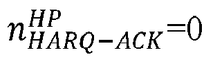
- in a case that a HARQ-ACK codebook is configured for the HARQ-ACK of the first priority and the first HARQ-ACK is transmitted over the PUCCH,

- In a possible implementation, the bit number

- in a case that no HARQ-ACK codebook is configured for the HARQ-ACK of the second priority and the second HARQ-ACK is transmitted over the PUCCH,

- in a case that no second HARQ-ACK is transmitted over the PUCCH,

- in a case that a HARQ-ACK codebook is configured for the HARQ-ACK of the second priority and the second HARQ-ACK is transmitted over the PUCCH,

- In a possible implementation, the determining, by the second determining
module 302, a PUCCH transmission power adjustment factor for the PUCCH based on the first bit number includes: - in a case that the first bit number is greater than a threshold, determining the PUCCH transmission power adjustment factor Δ TF,b,f,c (i) in the following manner:

- K2 is a second predetermined value; and
- BPRE(i) = (OACK (i) + OSR (i) + OCSI (i) + OCRC (i))/NRE (i); where OACK (i) is a second bit number, and the second bit number is determined based on a bit number of first hybrid automatic repeat request acknowledgement HARQ-ACK of the first priority transmitted over the PUCCH and/or a bit number of second HARQ-ACK of the second priority transmitted over the PUCCH; OSR (i) is a third bit number, where the third bit number is determined based on a bit number of a first scheduling request SR of the first priority transmitted over the PUCCH and/or a bit number of a second SR of the second priority transmitted over the PUCCH; OCSI (i) is a fourth bit number, where the fourth bit number is determined based on a bit number of first channel state information CSI of the first priority transmitted over the PUCCH and/or a bit number of second CSI of the second priority transmitted over the PUCCH; OCRC (i) is a fifth bit number, where the fifth bit number is determined based on a bit number of first cyclic redundancy check CRC of the first priority transmitted over the PUCCH and/or a bit number of second CRC of the second priority transmitted over the PUCCH; and NRE (i) is the number of first REs, where the number of first REs is determined based on the number of REs occupied by the first UCI and/or the number of REs occupied by the second UCI.
- In a possible implementation, the fifth bit number OCRC (i) is:


- In a possible implementation, the third bit number OSR (i) is:


- In a possible implementation, the fourth bit number OCSI (i) is:


- In a possible implementation, where the number of first REs NRE (i) is:


- In a possible implementation, the format of the PUCCH includes one of the following: PUCCH format 0 and PUCCH format 1.
- In a possible implementation, the second determining
module 302 determines the PUCCH transmission power adjustment factor ΔTF,b,f,c (i) in the following manner:

- in a case that the format of the PUCCH is PUCCH format 0,


- in a case that the format of the PUCCH is PUCCH format 0, Δ UCI (i) = 0, and in a case that the format of the PUCCH is PUCCH format 1, Δ UCI (i) = 10log 10(OUCI (i)), where OUCI (i) is the first bit number.
- In a possible implementation, the first bit number is:


- In the technical solution provided in this embodiment of this application, when the first determining module determines to multiplex the LP UCI and the HP UCI on one PUCCH, the second determining module determines the power for the PUCCH transmission based on the bit number of the LP UCI and/or the HP UCI, improving the effectiveness of the communication system.
- The apparatus for controlling a power for a PUCCH transmission in this embodiment of this application may be an apparatus, or may be a component, an integrated circuit, or a chip in a terminal. The apparatus may be a mobile terminal or a non-mobile terminal. For example, the mobile terminal may include but is not limited to the types of the terminal 11 listed above, and the non-mobile terminal may be a server, a network attached storage (Network Attached Storage, NAS), a personal computer (personal computer, PC), a television (Television, TV), a teller machine, a self-service machine, and the like, which are not specifically limited in this embodiment of this application.
- The apparatus for controlling a power for a PUCCH transmission in this embodiment of this application may be an apparatus with an operating system. The operating system may be an android (Android) operating system, may be an iOS operating system, or may be another possible operating system. This is not specifically limited in this embodiment of this application.
- The apparatus for controlling a power for a PUCCH transmission provided in this embodiment of this application can implement the processes implemented in the method embodiment in
FIG. 2 , with the same technical effects achieved. To avoid repetition, details are not described herein again. - Optionally, as shown in
FIG. 4 , an embodiment of this application further provides acommunication device 400 including aprocessor 401, amemory 402, and a program or instructions stored in thememory 402 and capable of running on theprocessor 401. For example, when thecommunication device 400 is a terminal and when the program or instructions are executed by theprocessor 401, the processes of the foregoing embodiments of the method for controlling a power for a PUCCH transmission are implemented, with the same technical effects achieved. When thecommunication device 400 is a network-side device and when the program or instructions are executed by theprocessor 401, the processes of the foregoing embodiments of the method for controlling a power for a PUCCH transmission are implemented, with the same technical effects achieved. To avoid repetition, details are not described herein again. - An embodiment of this application further provides a terminal including a processor and a communication interface, where the processor is applied to the processes of the foregoing embodiments of the method for controlling a power for a PUCCH transmission, and the communication interface is configured to communicate with other communication devices, for example, to communicate with other terminals or network-side devices. This terminal embodiment corresponds to the foregoing method embodiments on the terminal side. All implementation processes and implementation manners in the foregoing method embodiments may be applicable to this terminal embodiment, with the same technical effects achieved. Specifically,
FIG. 5 is a schematic diagram of a hardware structure of a terminal for implementing the embodiments of this application. - The terminal 500 includes but is not limited to components such as a
radio frequency unit 501, anetwork module 502, anaudio output unit 503, aninput unit 504, asensor 505, adisplay unit 506, auser input unit 507, aninterface unit 508, amemory 509, and aprocessor 510. - It can be understood by those skilled in the art that the terminal 500 may further include a power supply (for example, a battery) supplying power to the components. The power supply may be logically connected to the
processor 510 via a power management system, so that functions such as charge management, discharge management, and power consumption management are implemented by using the power management system. The structure of the terminal shown inFIG. 5 does not constitute any limitation on the terminal, and the terminal may include more or fewer components than shown in the figure, or combine some of the components, or have different arrangements of the components. Details are not described herein. - It should be understood that in this embodiment of this application, the
input unit 504 may include a graphics processing unit (Graphics Processing Unit, GPU) 5041 and amicrophone 5042. Thegraphics processing unit 5041 processes image data of a static picture or a video that is obtained by an image capture apparatus (for example, a camera) in a video capture mode or an image capture mode. Thedisplay unit 506 may include adisplay panel 5061. Thedisplay panel 5061 may be configured in a form of a liquid crystal display, an organic light-emitting diode display, or the like. Theuser input unit 507 includes atouch panel 5071 andother input devices 5072. Thetouch panel 5071 is also referred to as a touchscreen. Thetouch panel 5071 may include two parts: a touch detection apparatus and a touch controller. Theother input devices 5072 may include but are not limited to a physical keyboard, a function button (for example, a volume control button or a power on/off button), a trackball, a mouse, and a joystick. Details are not described herein again. - In the embodiments of this application, the
radio frequency unit 501 sends downlink data received from a network-side device to theprocessor 510 for processing, and in addition, sends uplink data to the network-side device. Generally, theradio frequency unit 501 includes but is not limited to an antenna, at least one amplifier, a transceiver, a coupler, a low noise amplifier, a duplexer, and the like. - The
memory 509 may be configured to store software programs or instructions and various data. Thememory 509 may include a program or instruction storage area and a data storage area. The program or instruction storage area may store an operating system, an application program or instruction required by at least one function (for example, a sound playback function or an image playback function), and the like. In addition, thememory 509 may include a high-speed random access memory, and may further include a non-volatile memory, where the non-transitory memory may be a read-only memory (Read-Only Memory, ROM), a programmable read-only memory (Programmable ROM, PROM), an erasable programmable read-only memory (Erasable PROM, EPROM), an electrically erasable programmable read-only memory (Electrically EPROM, EEPROM), or a flash memory. For example, at least one disk storage device, flash memory device, or another non-transitory solid-state storage device. - The
processor 510 may include one or more processing units. Optionally, theprocessor 510 may integrate an application processor and a modem processor. The application processor mainly processes an operating system, a user interface, an application program, instructions, or the like. The modem processor mainly processes wireless communication, for example, being a baseband processor. It can be understood that the modem processor may alternatively be not integrated in theprocessor 510. - The
processor 510 is configured to determine first UCI and second UCI multiplexed on one PUCCH for transmission, where a priority of the first UCI is a first priority, a priority of the second UCI is a second priority, and the first priority is higher than the second priority; and determine a power for a PUCCH transmission based on a first bit number, where the first bit number is determined based on a bit number of the first UCI and/or a bit number of the second UCI. - Optionally, the determining a power for a PUCCH transmission based on a first bit number includes:
- determining a PUCCH transmission power adjustment factor for the PUCCH based on the first bit number; and
- determining the power for the PUCCH transmission based on the PUCCH transmission power adjustment factor.
- Optionally, a format of the PUCCH includes one of the following: PUCCH format 2, PUCCH format 3, and PUCCH format 4.
- Optionally, the determining a PUCCH transmission power adjustment factor based on the first bit number includes:
- in a case that the first bit number is less than or equal to a threshold, the terminal determines the PUCCH transmission power adjustment factor Δ TF,b,f,c (i) in the following manner:

- K1 is a first predetermined value;
- nHARQ-ACK (i) is a second bit number, where the second bit number is determined based on a bit number of first hybrid automatic repeat request acknowledgement HARQ-ACK of the first priority transmitted over the PUCCH and/or a bit number of second HARQ-ACK of the second priority transmitted over the PUCCH;
- OSR (i) is a third bit number, where the third bit number is determined based on a bit number of a first scheduling request SR of the first priority transmitted over the PUCCH and/or a bit number of a second SR of the second priority transmitted over the PUCCH;
- OCSI (i) is a fourth bit number, where the fourth bit number is determined based on a bit number of first channel state information CSI of the first priority transmitted over the PUCCH and/or a bit number of second CSI of the second priority transmitted over the PUCCH; and
- NRE (i) is the number of first REs, where the number of first REs is determined based on the number of resource elements REs occupied by the first UCI and/or the number of resource elements REs occupied by the second UCI.
- Optionally, the second bit number nHARQ-ACK (i) is determined in the following manner:


- Optionally, the determining a PUCCH transmission power adjustment factor based on the first bit number includes:
- in a case that the first bit number is greater than a threshold, determining the PUCCH transmission power adjustment factor Δ TF,b,f,c (i)in the following manner:

- K2 is a second predetermined value; and
- BPRE(i) = (OACK (i) + OSR (i) + OCSI (i) + OCRC (i))/NRE (i), where OACK (i) is a second bit number, and the second bit number is determined based on a bit number of first hybrid automatic repeat request acknowledgement HARQ-ACK of the first priority transmitted over the PUCCH and/or a bit number of second HARQ-ACK of the second priority transmitted over the PUCCH; OSR (i) is a third bit number, where the third bit number is determined based on a bit number of a first scheduling request SR of the first priority transmitted over the PUCCH and/or a bit number of a second SR of the second priority transmitted over the PUCCH; OCSI (i) is a fourth bit number, where the fourth bit number is determined based on a bit number of first channel state information CSI of the first priority transmitted over the PUCCH and/or a bit number of second CSI of the second priority transmitted over the PUCCH; OCRC (i) is a fifth bit number, where the fifth bit number is determined based on a bit number of first cyclic redundancy check CRC of the first priority transmitted over the PUCCH and/or a bit number of second CRC of the second priority transmitted over the PUCCH; and NRE (i) is the number of first REs, where the number of first REs is determined based on the number of REs occupied by the first UCI and/or the number of REs occupied by the second UCI.
- An embodiment of this application further provides a readable storage medium, where a program or instructions are stored in the readable storage medium. When the program or instructions are executed by a processor, the processes of the foregoing embodiments of the method for controlling a power for a PUCCH transmission can be implemented, with the same technical effects achieved. To avoid repetition, details are not described herein again.
- The processor is a processor in the terminal described in the foregoing embodiments. The readable storage medium includes a computer-readable storage medium, such as a computer read-only memory (Read-Only Memory, ROM), a random access memory (Random Access Memory, RAM), a magnetic disk, or an optical disc.
- An embodiment of this application further provides a chip. The chip includes a processor and a communication interface, where the communication interface is coupled to the processor, and the processor is configured to run a program or instructions to implement the processes of the foregoing embodiments of the method for controlling a power for a PUCCH transmission, with the same technical effects achieved. To avoid repetition, details are not described herein again.
- It should be understood that the chip mentioned in this embodiment of this application may also be referred to as a system-level chip, a system chip, a chip system, a system-on-chip, or the like.
- An embodiment of this application further provides a computer program/program product, where the computer program/program product is stored in a non-transitory storage medium. When the program/program product is executed by at least one processor, the processes of the foregoing embodiments of the method for controlling a power for a PUCCH transmission are implemented, with the same technical effects achieved. To avoid repetition, details are not described herein again.
- It should be noted that in this specification, the terms "include", "comprise", or any of their variants are intended to cover a non-exclusive inclusion, such that a process, method, article, or apparatus that includes a series of elements includes not only those elements but also other elements that are not expressly listed, or further includes elements inherent to such process, method, article, or apparatus. Without more constraints, an element preceded by "includes a..." does not preclude the presence of other identical elements in the process, method, article, or apparatus that includes the element. Furthermore, it should be noted that the scope of the methods and apparatuses in the embodiments of this application is not limited to performing the functions in the order shown or discussed, but may also include performing the functions in a substantially simultaneous manner or in a reverse order depending on the functions involved. For example, the described methods may be performed in an order different from that described, and various steps may be added, omitted, or combined. In addition, features described with reference to some examples may be combined in other examples.
- By means of the foregoing description of the implementations, persons skilled in the art may clearly understand that the method in the foregoing embodiment may be implemented by software with a necessary general hardware platform. Certainly, the method in the foregoing embodiment may also be implemented by hardware. However, in many cases, the former is a preferred implementation. Based on such an understanding, the technical solutions of this application essentially, or the part contributing to the prior art may be implemented in a form of a computer software product. The computer software product is stored in a storage medium (for example, a ROM/RAM, a magnetic disk, or an optical disc), and includes several instructions for instructing a terminal (which may be a mobile phone, a computer, a server, an air conditioner, a network device, or the like) to perform the methods described in the embodiments of this application.
- The foregoing describes the embodiments of this application with reference to the accompanying drawings. However, this application is not limited to the foregoing specific embodiments. The foregoing specific embodiments are merely illustrative rather than restrictive. As instructed by this application, persons of ordinary skill in the art may develop many other manners without departing from the principle of this application and the protection scope of the claims, and all such manners fall within the protection scope of this application.
Claims (33)
- A method for controlling a power for a physical uplink control channel PUCCH transmission, comprising:determining, by a terminal, first uplink control information UCI and second UCI multiplexed on one PUCCH for transmission, wherein a priority of the first UCI is a first priority, a priority of the second UCI is a second priority, and the first priority is higher than the second priority; anddetermining, by the terminal, a power for the PUCCH transmission based on a first bit number, wherein the first bit number is determined based on a bit number of the first UCI and/or a bit number of the second UCI.
- The method according to claim 1, wherein the determining, by the terminal, a power for the PUCCH transmission based on a first bit number comprises:determining, by the terminal, a PUCCH transmission power adjustment factor for the PUCCH based on the first bit number; anddetermining the power for the PUCCH transmission based on the PUCCH transmission power adjustment factor.
- The method according to claim 2, wherein the determining, by the terminal, a PUCCH transmission power adjustment factor based on the first bit number comprises:in a case that the first bit number is less than or equal to a threshold, determining, by the terminal, the PUCCH transmission power adjustment factor ΔTF,b,f,c (i) in the following manner:
 nHARQ-ACK (i) is a second bit number, wherein the second bit number is determined based on a bit number of first hybrid automatic repeat request acknowledgement HARQ-ACK of the first priority transmitted over the PUCCH and/or a bit number of second HARQ-ACK of the second priority transmitted over the PUCCH;OSR (i) is a third bit number, wherein the third bit number is determined based on a bit number of a first scheduling request SR of the first priority transmitted over the PUCCH and/or a bit number of a second SR of the second priority transmitted over the PUCCH;OCSI (i) is a fourth bit number, wherein the fourth bit number is determined based on a bit number of first channel state information CSI of the first priority transmitted over the PUCCH and/or a bit number of second CSI of the second priority transmitted over the PUCCH; andNRE (i) is a number of first resource elements REs, wherein the number of the first REs is determined based on a number of REs occupied by the first UCI and/or a number of REs occupied by the second UCI.
 - The method according to claim 3, wherein the second bit number nHARQ-ACK (i) is determined in the following manner:


- The method according to claim 4, wherein the bit number
 in a case that no HARQ-ACK codebook is configured for HARQ-ACK of the first priority of the terminal and the first HARQ-ACK is transmitted over the PUCCH,
 in a case that no first HARQ-ACK is transmitted over the PUCCH,
 in a case that the first HARQ-ACK is transmitted over the PUCCH,
- The method according to claim 4 or 5, wherein the bit number
 in a case that no HARQ-ACK codebook is configured for HARQ-ACK of the second priority of the terminal and that the second HARQ-ACK is transmitted over the PUCCH,
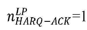 in a case that no second HARQ-ACK is transmitted over the PUCCH,
 in a case that a HARQ-ACK codebook is configured for the HARQ-ACK of the second priority of the terminal and the second HARQ-ACK is transmitted over the PUCCH,
- The method according to claim 2, wherein the determining, by the terminal, a PUCCH transmission power adjustment factor based on the first bit number comprises:in a case that the first bit number is greater than a threshold, determining, by the terminal, the PUCCH transmission power adjustment factor Δ TF,b,f,c (i) in the following manner:

 OACK (i) is a second bit number, wherein the second bit number is determined based on a bit number of first hybrid automatic repeat request acknowledgement HARQ-ACK of the first priority transmitted over the PUCCH and/or a bit number of second HARQ-ACK of the second priority transmitted over the PUCCH;OSR (i) is a third bit number, wherein the third bit number is determined based on a bit number of a first SR of the first priority transmitted over the PUCCH and/or a bit number of a second SR of the second priority transmitted over the PUCCH;OCSI (i) is a fourth bit number, wherein the fourth bit number is determined based on a bit number of first channel state information CSI of the first priority transmitted over the PUCCH and/or a bit number of second CSI of the second priority transmitted over the PUCCH;OCRC (i) is a fifth bit number, wherein the fifth bit number is determined based on a bit number of first cyclic redundancy check CRC of the first priority transmitted over the PUCCH and/or a bit number of second CRC of the second priority transmitted over the PUCCH; andNRE (i) is a number of first REs, wherein the number of the first REs is determined based on a number of REs occupied by the first UCI and/or a number of REs occupied by the second UCI.
 - The method according to claim 7, wherein the fifth bit number OCRC (i) is:



- The method according to any one of claims 3 to 8, wherein the threshold is 11.
- The method according to any one of claims 3 to 9, wherein the third bit number OSR (i) is:


- The method according to any one of claims 3 to 10, wherein the fourth bit number OCSI (i) is:



- The method according to any one of claims 3 to 11, wherein the number of the first REs NRE (i) is:


- The method according to any one of claims 3 to 12, wherein a format of the PUCCH comprises one of the following: PUCCH format 2, PUCCH format 3, and PUCCH format 4.
- The method according to claim 2, wherein the terminal determines the PUCCH transmission power adjustment factor Δ TF,b,f,c (i) in the following manner:

 in a case that a format of the PUCCH is PUCCH format 0,

 in a case that the format of the PUCCH is the PUCCH format 0, Δ UCI (i) = 0; alternatively, in a case that the format of the PUCCH is the PUCCH format 1, Δ UCI (i) = 10log 10(OUCI (i)), wherein OUCI (i) is the first bit number.
 - The method according to claim 14, wherein the format of the PUCCH comprises one of the following: the PUCCH format 0 and the PUCCH format 1.
- The method according to any one of claims 1 to 15, wherein the first bit number is:


- An apparatus for controlling a power for a physical uplink control channel PUCCH transmission, comprising:a first determining module configured to determine first UCI and second UCI multiplexed on one PUCCH for transmission, wherein a priority of the first UCI is a first priority, a priority of the second UCI is a second priority, and the first priority is higher than the second priority; anda second determining module configured to determine a power for the PUCCH transmission based on a first bit number, wherein the first bit number is determined based on a bit number of the first UCI and/or a bit number of the second UCI.
- The apparatus according to claim 17, wherein the determining, by the second determining module, a power for the PUCCH transmission based on a first bit number comprises:determining a PUCCH transmission power adjustment factor for the PUCCH based on the first bit number; anddetermining the power for the PUCCH transmission based on the PUCCH transmission power adjustment factor.
- The apparatus according to claim 18, wherein the determining, by the second determining module, a PUCCH transmission power adjustment factor based on the first bit number comprises:in a case that the first bit number is less than or equal to a threshold, determining, by the terminal, the PUCCH transmission power adjustment factor ΔTF,b,f,c (i) in the following manner:
 K1 is a first predetermined value;nHARQ-ACK (i) is a second bit number, wherein the second bit number is determined based on a bit number of first hybrid automatic repeat request acknowledgement HARQ-ACK of the first priority transmitted over the PUCCH and/or a bit number of second HARQ-ACK of the second priority transmitted over the PUCCH;OSR (i) is a third bit number, wherein the third bit number is determined based on a bit number of a first scheduling request SR of the first priority transmitted over the PUCCH and/or a bit number of a second SR of the second priority transmitted over the PUCCH;OCSI (i) is a fourth bit number, wherein the fourth bit number is determined based on a bit number of first channel state information CSI of the first priority transmitted over the PUCCH and/or a bit number of second CSI of the second priority transmitted over the PUCCH; andNRE (i) is a number of first REs, wherein the number of the first REs is determined based on a number of resource elements REs occupied by the first UCI and/or a number of resource elements REs occupied by the second UCI.
 - The apparatus according to claim 19, wherein the second bit number nHARQ-ACK (i) is determined in the following manner:


- The apparatus according to claim 19, wherein the bit number
 in a case that no HARQ-ACK codebook is configured for HARQ-ACK of the first priority and the first HARQ-ACK is transmitted over the PUCCH,
 in a case that no first HARQ-ACK is transmitted over the PUCCH,
 in a case that a HARQ-ACK codebook is configured for the HARQ-ACK of the first priority and the first HARQ-ACK is transmitted over the PUCCH,
- The apparatus according to claim 19 or 20, wherein the bit number
 in a case that no HARQ-ACK codebook is configured for HARQ-ACK of the second priority and the second HARQ-ACK is transmitted over the PUCCH,
 in a case that no second HARQ-ACK is transmitted over the PUCCH,
 in a case that a HARQ-ACK codebook is configured for the HARQ-ACK of the second priority and the second HARQ-ACK is transmitted over the PUCCH,
- The apparatus according to claim 18, wherein the determining, by the second determining module, a PUCCH transmission power adjustment factor based on the first bit number comprises:in a case that the first bit number is greater than a threshold, determining the PUCCH transmission power adjustment factor Δ TF,b,f,c (i) in the following manner:
 BPRE(i) = (OACK (i) + OSR (i) + OCSI (i) + OCRC (i))/NRE (i), whereinOACK (i) is a second bit number, wherein the second bit number is determined based on a bit number of first hybrid automatic repeat request acknowledgement HARQ-ACK of the first priority transmitted over the PUCCH and/or a bit number of second HARQ-ACK of the second priority transmitted over the PUCCH;OSR (i) is a third bit number, wherein the third bit number is determined based on a bit number of a first SR of the first priority transmitted over the PUCCH and/or a bit number of a second SR of the second priority transmitted over the PUCCH;OSR (i) is a fourth bit number, wherein the fourth bit number is determined based on a bit number of first channel state information CSI of the first priority transmitted over the PUCCH and/or a bit number of second CSI of the second priority transmitted over the PUCCH;OSR (i) is a fifth bit number, wherein the fifth bit number is determined based on a bit number of first cyclic redundancy check CRC of the first priority transmitted over the PUCCH and/or a bit number of second CRC of the second priority transmitted over the PUCCH; andNRE (i) is a number of first REs, wherein the number of the first REs is determined based on a number of REs occupied by the first UCI and/or a number of REs occupied by the second UCI.
 - The apparatus according to claim 23, wherein the fifth bit number OCRC (i) is:


- The apparatus according to any one of claims 19 to 24, wherein the third bit number OSR (i) is:


- The apparatus according to any one of claims 19 to 25, wherein the fourth bit number OCSI (i) is:


- The apparatus according to any one of claims 19 to 26, wherein the number of the first REs NRE (i) is:


- The apparatus according to any one of claims 19 to 27, wherein a format of the PUCCH comprises one of the following: PUCCH format 2, PUCCH format 3, and PUCCH format 4.
- The apparatus according to claim 18, wherein the second determining module determines the PUCCH transmission power adjustment factor Δ TF,b,f,c (i) in the following manner:

 in a case that a format of the PUCCH is PUCCH format 0,


- The apparatus according to claim 29, wherein the format of the PUCCH comprises one of the following: the PUCCH format 0 and the PUCCH format 1.
- The apparatus according to any one of claims 17 to 30, wherein the first bit number is:


- A terminal, comprising a processor, a memory, and a program or instructions stored in the memory and capable of running on the processor, wherein when the program or instructions are executed by the processor, steps of the method for controlling the power for the PUCCH transmission according to any one of claims 1 to 16 are implemented.
- A readable storage medium, wherein a program or instructions are stored in the readable storage medium, and when the program or instructions are executed by a processor, steps of the method for controlling the power for the PUCCH transmission according to any one of claims 1 to 16 are implemented.
Applications Claiming Priority (2)
| Application Number | Priority Date | Filing Date | Title |
|---|---|---|---|
| CN202111130451.3A CN115884338A (en) | 2021-09-26 | 2021-09-26 | PUCCH transmission power control method, device and terminal |
| PCT/CN2022/121309 WO2023046162A1 (en) | 2021-09-26 | 2022-09-26 | Control method and apparatus for transmission power of pucch and terminal |
Publications (2)
| Publication Number | Publication Date |
|---|---|
| EP4408082A1 true EP4408082A1 (en) | 2024-07-31 |
| EP4408082A4 EP4408082A4 (en) | 2025-01-15 |
Family
ID=85720142
Family Applications (1)
| Application Number | Title | Priority Date | Filing Date |
|---|---|---|---|
| EP22872205.4A Pending EP4408082A4 (en) | 2021-09-26 | 2022-09-26 | Control method and apparatus for transmission power of pucch and terminal |
Country Status (6)
| Country | Link |
|---|---|
| US (1) | US20240236871A1 (en) |
| EP (1) | EP4408082A4 (en) |
| JP (1) | JP2024533740A (en) |
| KR (1) | KR20240060704A (en) |
| CN (1) | CN115884338A (en) |
| WO (1) | WO2023046162A1 (en) |
Family Cites Families (10)
| Publication number | Priority date | Publication date | Assignee | Title |
|---|---|---|---|---|
| WO2013112004A1 (en) * | 2012-01-27 | 2013-08-01 | 엘지전자 주식회사 | Method and apparatus for transmitting uplink control information in wireless communication system |
| CN112615707B (en) * | 2015-06-19 | 2024-04-23 | 北京三星通信技术研究有限公司 | A method for transmitting uplink control information |
| CN106257856B (en) * | 2015-06-19 | 2021-02-02 | 北京三星通信技术研究有限公司 | Method for transmitting uplink control information |
| CN109600847B (en) * | 2017-09-30 | 2025-01-21 | 北京三星通信技术研究有限公司 | Method and device for transmitting uplink control information and setting uplink timing advance |
| WO2019172624A1 (en) * | 2018-03-05 | 2019-09-12 | 엘지전자 주식회사 | Method for transmitting uplink channel in wireless communication system and device for supporting same |
| US10708866B2 (en) * | 2018-04-05 | 2020-07-07 | Samsung Electronics Co., Ltd. | Signaling of control information in a communication system |
| CN111835480B (en) * | 2019-07-05 | 2021-11-19 | 维沃移动通信有限公司 | UCI transmission method, UCI receiving method, terminal and network equipment |
| CN119544169A (en) * | 2019-12-30 | 2025-02-28 | 北京三星通信技术研究有限公司 | Terminal, base station and method in wireless communication system |
| US20220109529A1 (en) * | 2020-10-05 | 2022-04-07 | Samsung Electronics Co., Ltd. | Harq-ack information disabling in communication systems |
| CN115943683B (en) * | 2021-08-05 | 2025-09-19 | 苹果公司 | Method, medium and baseband processor for power control for inter-layer priority uplink control information multiplexing |
-
2021
- 2021-09-26 CN CN202111130451.3A patent/CN115884338A/en active Pending
-
2022
- 2022-09-26 KR KR1020247013529A patent/KR20240060704A/en active Pending
- 2022-09-26 JP JP2024518934A patent/JP2024533740A/en active Pending
- 2022-09-26 WO PCT/CN2022/121309 patent/WO2023046162A1/en not_active Ceased
- 2022-09-26 EP EP22872205.4A patent/EP4408082A4/en active Pending
-
2024
- 2024-03-25 US US18/614,897 patent/US20240236871A1/en active Pending
Also Published As
| Publication number | Publication date |
|---|---|
| EP4408082A4 (en) | 2025-01-15 |
| CN115884338A (en) | 2023-03-31 |
| WO2023046162A1 (en) | 2023-03-30 |
| JP2024533740A (en) | 2024-09-12 |
| US20240236871A1 (en) | 2024-07-11 |
| KR20240060704A (en) | 2024-05-08 |
Similar Documents
| Publication | Publication Date | Title |
|---|---|---|
| CN115362738B (en) | Apparatus and method for transmitting PUSCH of UCI | |
| EP4280755A1 (en) | Transmission processing method and related device | |
| EP4277174A1 (en) | Method and apparatus for determining number of coded modulation symbols, and communication device | |
| US12520306B2 (en) | Uplink channel transmission method and apparatus, and terminal | |
| EP3496472B1 (en) | Power control method, apparatus and system for short transmission time interval transmission and storage medium | |
| EP4280757A1 (en) | Configuration processing method and apparatus for configured grant, device, and storage medium | |
| US20230171751A1 (en) | Collision processing method and apparatus | |
| US12526808B2 (en) | Information processing method and apparatus, and user equipment | |
| US12538303B2 (en) | Information multiplexing method and apparatus, and user equipment | |
| US20230354324A1 (en) | Uci multiplexing method and apparatus, device, and readable storage medium | |
| US20230254867A1 (en) | Uplink transmission processing method and apparatus, and terminal | |
| US12113625B2 (en) | HARQ-ACK feedback method and apparatus | |
| US20240080818A1 (en) | Method and apparatus for determining uplink transmission time window, terminal, and network-side device | |
| US20260067887A1 (en) | Transmission information determining method, configuration information sending method, terminal, and device | |
| EP4266820A1 (en) | Method and device for communication processing, and communication device | |
| CN114390657A (en) | Power determination method, device, terminal and readable storage medium | |
| CN113965301A (en) | Method and device for processing physical uplink control channel resource overlapping | |
| US20240080844A1 (en) | Uplink Control Information UCI Transmission Method and Apparatus, User Equipment, and Medium | |
| EP4221035A1 (en) | Transmission information determination method and device, and terminal | |
| US20240236871A1 (en) | Method and Apparatus for Controlling Power for PUCCH Transmission and Terminal | |
| EP4369741A1 (en) | Method and apparatus for processing overlapping pucch time domain resources | |
| CN114337950B (en) | Transmission processing method, device, terminal and readable storage medium | |
| US20260136385A1 (en) | Method and apparatus for determining number of coded modulation symbols, and communications device | |
| EP4380275A1 (en) | Uplink transmission method and apparatus, and terminal | |
| EP4408099A1 (en) | Resource determination method and apparatus, and terminal and readable storage medium |
Legal Events
| Date | Code | Title | Description |
|---|---|---|---|
| STAA | Information on the status of an ep patent application or granted ep patent |
Free format text: STATUS: THE INTERNATIONAL PUBLICATION HAS BEEN MADE |
|
| PUAI | Public reference made under article 153(3) epc to a published international application that has entered the european phase |
Free format text: ORIGINAL CODE: 0009012 |
|
| STAA | Information on the status of an ep patent application or granted ep patent |
Free format text: STATUS: REQUEST FOR EXAMINATION WAS MADE |
|
| 17P | Request for examination filed |
Effective date: 20240423 |
|
| AK | Designated contracting states |
Kind code of ref document: A1 Designated state(s): AL AT BE BG CH CY CZ DE DK EE ES FI FR GB GR HR HU IE IS IT LI LT LU LV MC MK MT NL NO PL PT RO RS SE SI SK SM TR |
|
| DAV | Request for validation of the european patent (deleted) | ||
| DAX | Request for extension of the european patent (deleted) | ||
| A4 | Supplementary search report drawn up and despatched |
Effective date: 20241212 |
|
| RIC1 | Information provided on ipc code assigned before grant |
Ipc: H04L 1/1607 20230101ALI20241206BHEP Ipc: H04W 52/32 20090101ALI20241206BHEP Ipc: H04W 52/28 20090101ALI20241206BHEP Ipc: H04L 5/00 20060101ALI20241206BHEP Ipc: H04L 1/1829 20230101ALI20241206BHEP Ipc: H04L 1/1812 20230101ALI20241206BHEP Ipc: H04W 52/14 20090101AFI20241206BHEP |