EP4407915A1 - Channel separation method and system - Google Patents
Channel separation method and system Download PDFInfo
- Publication number
- EP4407915A1 EP4407915A1 EP23787799.8A EP23787799A EP4407915A1 EP 4407915 A1 EP4407915 A1 EP 4407915A1 EP 23787799 A EP23787799 A EP 23787799A EP 4407915 A1 EP4407915 A1 EP 4407915A1
- Authority
- EP
- European Patent Office
- Prior art keywords
- codebook
- base station
- terminal
- reflecting surface
- pilot
- Prior art date
- Legal status (The legal status is an assumption and is not a legal conclusion. Google has not performed a legal analysis and makes no representation as to the accuracy of the status listed.)
- Pending
Links
Images



Classifications
-
- H—ELECTRICITY
- H04—ELECTRIC COMMUNICATION TECHNIQUE
- H04B—TRANSMISSION
- H04B7/00—Radio transmission systems, i.e. using radiation field
- H04B7/02—Diversity systems; Multi-antenna system, i.e. transmission or reception using multiple antennas
- H04B7/04—Diversity systems; Multi-antenna system, i.e. transmission or reception using multiple antennas using two or more spaced independent antennas
- H04B7/04013—Intelligent reflective surfaces
- H04B7/04026—Intelligent reflective surfaces with codebook-based beamforming
-
- H—ELECTRICITY
- H04—ELECTRIC COMMUNICATION TECHNIQUE
- H04L—TRANSMISSION OF DIGITAL INFORMATION, e.g. TELEGRAPHIC COMMUNICATION
- H04L25/00—Baseband systems
- H04L25/02—Details ; arrangements for supplying electrical power along data transmission lines
- H04L25/0202—Channel estimation
- H04L25/0204—Channel estimation of multiple channels
-
- H—ELECTRICITY
- H04—ELECTRIC COMMUNICATION TECHNIQUE
- H04L—TRANSMISSION OF DIGITAL INFORMATION, e.g. TELEGRAPHIC COMMUNICATION
- H04L25/00—Baseband systems
- H04L25/02—Details ; arrangements for supplying electrical power along data transmission lines
- H04L25/0202—Channel estimation
- H04L25/0224—Channel estimation using sounding signals
- H04L25/0226—Channel estimation using sounding signals sounding signals per se
-
- H—ELECTRICITY
- H04—ELECTRIC COMMUNICATION TECHNIQUE
- H04L—TRANSMISSION OF DIGITAL INFORMATION, e.g. TELEGRAPHIC COMMUNICATION
- H04L25/00—Baseband systems
- H04L25/02—Details ; arrangements for supplying electrical power along data transmission lines
- H04L25/0202—Channel estimation
- H04L25/0224—Channel estimation using sounding signals
- H04L25/0228—Channel estimation using sounding signals with direct estimation from sounding signals
-
- H—ELECTRICITY
- H04—ELECTRIC COMMUNICATION TECHNIQUE
- H04L—TRANSMISSION OF DIGITAL INFORMATION, e.g. TELEGRAPHIC COMMUNICATION
- H04L5/00—Arrangements affording multiple use of the transmission path
- H04L5/003—Arrangements for allocating sub-channels of the transmission path
- H04L5/0048—Allocation of pilot signals, i.e. of signals known to the receiver
- H04L5/005—Allocation of pilot signals, i.e. of signals known to the receiver of common pilots, i.e. pilots destined for multiple users or terminals
-
- H—ELECTRICITY
- H04—ELECTRIC COMMUNICATION TECHNIQUE
- H04L—TRANSMISSION OF DIGITAL INFORMATION, e.g. TELEGRAPHIC COMMUNICATION
- H04L5/00—Arrangements affording multiple use of the transmission path
- H04L5/003—Arrangements for allocating sub-channels of the transmission path
- H04L5/0048—Allocation of pilot signals, i.e. of signals known to the receiver
- H04L5/0051—Allocation of pilot signals, i.e. of signals known to the receiver of dedicated pilots, i.e. pilots destined for a single user or terminal
Definitions
- Embodiments of the present disclosure relate to the field of communications, and in particular, to a channel separation method and system.
- intelligent reflecting surfaces have become a hot research topic in the Beyond 5th Generation wireless communication system (B5G) and the 6th Generation wireless communication system (6G). With the assistance of intelligent reflecting surfaces, it is possible to greatly eliminate blind spots and improve the capacity of hot spot areas through the reflection of wireless signals.
- B5G 5th Generation wireless communication system
- 6G 6th Generation wireless communication system
- Fig. 1 is a schematic diagram of channels between a base station and a terminal when an intelligent reflecting surface is adopted in the related art.
- there are two types of channels between the base station and the terminal one is a direct channel H d
- the direct channel H d and the reflection channel H r may have time and angle offsets, which may seriously affect channel estimation and demodulation performance in some scenarios.
- the communication system in the related art does not consider the separation of the direct channel and the reflection channel, which results in that the channels received by the base station or the terminal are mixed.
- Embodiments of the present disclosure provide a channel separation method and system, which may at least solve the problem in the related art that the channels received by the base station or the terminal are mixed.
- a channel separation method including: switching, by an intelligent reflecting surface or a relay between a base station and a terminal, a codebook of reflected pilot signals to a new codebook at a specified symbol position based on a pre-configured codebook reflection coefficient.
- a channel separation system including: an intelligent reflecting surface or a relay located between a base station and a terminal, and configured to switch a codebook of reflected pilot signals to a new codebook at a specified symbol position based on a pre-configured codebook reflection coefficient.
- a computer-readable storage medium stores a computer program, and the computer program, when executed by a processor, causes the processor to execute operations in any one of the method embodiments.
- an electronic device including a memory and a processor, wherein the memory stores a computer program, and the processor is configured to run the computer program so as to execute operations in any one of the described method embodiments.
- an intelligent reflecting surface or a relay is a low-cost solution for wireless signal enhancement.
- Fig. 1 in the case where an intelligent reflecting surface or a relay exists, there are two types of channels between the base station and the terminal, one is a direct channel H d , and the other is a reflection channel H r formed by the reflection of the intelligent reflecting surface, thus resulting in that the channels received by the base station or the terminal at a receiving end are mixed.
- the embodiments of the present disclosure provide a channel separation method and system, which are applied to the case where the intelligent reflecting surface or the relay exists, and can effectively separate the direct channel H d between the base station and the terminal and the reflection channel H r formed by the reflection of the intelligent reflecting surface, thereby improving performances such as demodulation and positioning.
- FIG. 2 is a flowchart of a channel separation method according to an embodiment of the present disclosure. As shown in Fig. 2 , the flow includes the following operation S202.
- an intelligent reflecting surface or a relay between a base station and a terminal switches a codebook of reflected pilot signals to a new codebook at a specified symbol position based on a pre-configured codebook reflection coefficient.
- the method before the intelligent reflecting surface or the relay switches the codebook of the reflected pilot signals to the new codebook at the specified symbol position, the method further includes: the base station notifies the terminal about configuration of the pilot signals, wherein the pilot signals appear as a group of two pilot symbols, and one or more groups of pilot symbols are configured.
- the two pilot symbols are continuous symbols or are two pilot symbols separated by at most one pilot symbol, the pilot signals of the two pilot symbols occupy the same Resource Block (RB), and the number of Resource Elements (REs) occupied on each RB is the same.
- RB Resource Block
- REs Resource Elements
- the pilot signals are Demodulation Reference Signals (DMRS), or Synchronization Signal Blocks (SSB), or Physical Random Access Signals (PRS), or Channel State Information Reference Signal (CSI-RS).
- DMRS Demodulation Reference Signals
- SSB Synchronization Signal Blocks
- PRS Physical Random Access Signals
- CSI-RS Channel State Information Reference Signal
- the method before the intelligent reflecting surface or the relay switches the codebook of the reflected pilot signals to the new codebook at the specified symbol position, the method further includes: the base station configures or makes an agreement on a parameter set for the intelligent reflecting surface or the relay, wherein the parameter set at least includes one of: a first parameter, a second parameter and a third parameter; wherein the first parameter is used for indicating the codebook reflection coefficient; the second parameter is used for indicating at which pilot symbol positions the intelligent reflecting surface or the relay switches the codebook of the reflected pilot signals; the third parameter is used for indicating time when the intelligent reflecting surface or the relay switches the codebook of the reflected pilot signals, wherein the time includes at least one of: a time slot, and a pilot frequency symbol.
- the intelligent reflecting surface or the relay switches the codebook of the reflected pilot signals to the new codebook in a following manner: the intelligent reflecting surface or the relay switches the codebook of the pilot signals from an old codebook to the new codebook on one of the two pilot symbols, wherein the new codebook is obtained by multiplying the old codebook by the codebook reflection coefficient.
- the method further includes: after receiving the pilot signals, the terminal or the base station separates a direct channel between the base station and the terminal and a reflection channel formed by reflection of the intelligent reflecting surface or the relay according to the codebook on different pilot symbols of the pilot signals.
- the method further includes: the terminal feeds back, based on measurement feedback signaling, a measurement result of the direct channel and a measurement result of the reflection channel separately or jointly.
- the intelligent reflecting surface or the relay switches the codebook of reflected pilot signals to the new codebook at the specified symbol position based on the pre-configured codebook reflection coefficient, so as to construct code division of a direct channel and a reflection channel in the time domain.
- the terminal or the base station may perform channel separation according to the received pilot signals, thereby effectively separating the direct channel and the reflection channel between the base station and the terminal. Therefore, the problem in the related art that the channels received by the base station or the terminal are mixed can be solved, thereby improving the positioning precision and achieving the effects of improving performances such as wireless signal demodulating performance and positioning performance.
- the computer software product may be stored in a storage medium (such as Read-Only Memory/Random Access Memory (ROM/RAM), magnetic disk, and optical disk), and may include several instructions for instructing a terminal device (which may be a mobile phone or a computer), a server, a network device, or the like to perform the methods described in the embodiments of the present disclosure.
- a storage medium such as Read-Only Memory/Random Access Memory (ROM/RAM), magnetic disk, and optical disk
- a channel separation system is also provided in the embodiment.
- the system is used for implementing the described embodiments and exemplary implementations, and what has been described will not be elaborated.
- the term "module”, as used hereinafter, is a combination of software and/or hardware capable of realizing a predetermined function.
- the apparatus described in the following embodiment is preferably implemented by software, implementation of hardware or a combination of software and hardware is also possible and conceived.
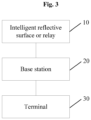
- Fig. 3 is a structural block diagram of a channel separation system according to an embodiment of the present disclosure. As shown in Fig. 3 , the system includes an intelligent reflecting surface or a relay 10, a base station 20 and a terminal 30.
- the intelligent reflecting surface or relay 10 is located between the base station 20 and the terminal 30 and is configured to switch a codebook of reflected pilot signals to a new codebook at a specified symbol position based on a pre-configured codebook reflection coefficient.
- the base station 20 is configured to notify the terminal about configuration of the pilot signals, wherein the pilot signals appear as a group of two pilot symbols, and one or more groups of pilot symbols are configured.
- the base station 20 or the terminal 30 is further configured to, after receiving the pilot signals, separate a direct channel between the base station and the terminal and a reflection channel formed by reflection of the intelligent reflecting surface or the relay according to the codebook on different pilot symbols of the pilot signals.
- the base station is further configured to configure or make an agreement on a parameter set for the intelligent reflecting surface or the relay, wherein the parameter set at least includes one of: a first parameter, a second parameter and a third parameter; wherein the first parameter is used for indicating the codebook reflection coefficient; the second parameter is used for indicating at which pilot symbol positions the intelligent reflecting surface or the relay switches the codebook of the reflected pilot signals; the third parameter is used for indicating time when the intelligent reflecting surface or the relay switches the codebook of the reflected pilot signals, wherein the time includes at least one of: a time slot, and a pilot frequency symbol.
- the parameter set at least includes one of: a first parameter, a second parameter and a third parameter; wherein the first parameter is used for indicating the codebook reflection coefficient; the second parameter is used for indicating at which pilot symbol positions the intelligent reflecting surface or the relay switches the codebook of the reflected pilot signals; the third parameter is used for indicating time when the intelligent reflecting surface or the relay switches the codebook of the reflected pilot signals, wherein the time
- the terminal is further configured to feed back, based on measurement feedback signaling, a measurement result of the direct channel and a measurement result of the reflection channel separately or jointly.
- each module may be implemented by software or hardware. The latter may be implemented in the following manner, but is not limited thereto. All the modules are located in a same processor; alternatively, the modules are located in different processors in an arbitrary combination.
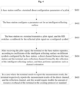
- Fig. 4 is a flowchart of a channel separation method when there is an intelligent reflecting surface according to an embodiment of the present disclosure. As shown in Fig. 4 , the method includes the following operations S401 to S405.
- a base station notifies a terminal about configuration parameters of a pilot signal.
- the configuration parameters of the pilot signal may indicate the pilot signal in the form of a group of two continuous symbols in the time domain, and one or more groups may be configured.
- the base station configures a parameter set for a Reconfigurable Intelligence Surface (RIS).
- RIS Reconfigurable Intelligence Surface
- the parameter set includes three parts:
- the base station or the terminal transmits a pilot signal, and the RIS switches a codebook for the reflected pilot signal on the configured symbol.
- the new codebook to be switched to is obtained by multiplying the original codebook by a specified scalar, for example, for a 1-bit intelligent reflecting surface, the codebook of the intelligent reflecting surface may be multiplied by -1 on the second pilot symbol of two continuous symbols occupied by the reference signal.
- Other forms of codebook coefficient may also be used in this embodiment.
- the terminal or the base station After receiving the pilot signal, the terminal or the base station separates, according to the coefficients, configured by the base station, of the intelligent reflecting surface on different symbols, a direct channel between the base station and the terminal and a reflection channel formed by the reflection of the intelligent reflecting surface, and then performs operations such as channel estimation.
- the terminal in a case where the terminal needs to report the measurement result, the terminal respectively reports the measurement results of the direct channel and the reflection channel, and this would require double the amount of resource overhead of the terminal in the existing protocol or standard.
- This embodiment also provides possible time domain situations when the coefficient of the codebook of the RIS is switched under a configuration of a 2-symbol pilot signal and under a configuration of a 4-symbol pilot signal respectively.
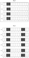
- a time domain position of the pilot symbols and the corresponding coefficient of the intelligent reflecting surface can be represented by Fig. 5.
- Fig. 5 shows 14 symbols (namely, symbol 0 to symbol 13) in a slot, in which the position where a black box is located is the position of a pilot, and if there is -1 in the box where the symbol is located, it represents that the codebook of the intelligent reflecting surface on the symbol is obtained by multiplying the original codebook by -1.
- the combined channel on symbol 0 and symbol 1 in Fig. 5(c) may be represented as H d + H f
- the combined channel on symbol 4 to symbol 13 in Fig. 5(c) may be represented as H d - H f .
- the combined channel on symbol 0 and symbol 1 in Fig. 5(d) may be represented as H d - H f
- the combined channel on symbol 4 to symbol 13 in Fig. 5(d) may be represented as H d + H f .
- a time domain position of the pilot symbols and the corresponding coefficient of the intelligent reflecting surface can be represented by Fig. 6 .
- the combined channel in Fig. 6(a), Fig. 6(b), Fig. 6(c) and Fig. 6(d) may be expressed as H d + H f .
- the combined channel on symbol 0, symbol 1, symbol 12 and symbol 13 in Fig. 6(e) may be represented as H d + H f
- the combined channel on symbol 4 to symbol 9 in Fig. 6(e) may be represented as H d - H f .
- the combined channel on symbol 0, symbol 1, symbol 12 and symbol 13 in Fig. 6(f) may be represented as H d - H f
- the combined channel on symbol 4 to symbol 9 in Fig. 6(f) may be represented as H d + H f .
- Fig. 7 is a flowchart of a downlink channel separation method according to an embodiment of the present disclosure. As shown in Fig. 7 , the method includes the following operations S701 to S705.
- a base station notifies a terminal about configuration parameters of a downlink pilot signal.
- the configuration parameters of the pilot signal may indicate the pilot signal in the form of a group of two continuous symbols in the time domain, and one or more groups may be configured. For example, assuming that a pilot signal is configured on symbol 2 and symbol 3, the parameter configured by the base station for the terminal indicates that the codebook starting from symbol 3 is to be multiplied by -1 by the intelligent reflecting surface, or the base station and the terminal agrees in advance that the second pilot symbol of two continuous pilot symbols is to be multiplied by -1.
- the base station may also configure feedback of the terminal, for example, the base station may configure the terminal to feed back channel measurement results of the direct channel and the reflection channel at the same time, including but not limited to parameters such as Reference Signal Receiving Power (RSRP), time delay, and signal-to-interference ratio.
- RSRP Reference Signal Receiving Power
- the base station configures a parameter set for RIS.
- the parameter set includes three parts:
- the base station transmits a downlink pilot signal, and the intelligent reflecting surface multiplies the codebook at the starting position where symbol 3 is received by -1.
- the terminal performs channel separation after receiving the pilot signal.
- the direct channel between the base station and the terminal may be denoted as ( H ls 2 + H ls 3 )/2
- the reflection channel formed by the reflection of the intelligent reflecting surface between the base station and the terminal may be denoted as ( H ls 2 - H ls 3 )/2.
- the terminal feeds back the measurement report with twice the amount of resource overhead.
- the measurement results for the direct channel and the reflection channel may be fed back jointly or separately.
- the base station configures parameters for the terminal.
- the configuration parameters need to include: the base station notifies the terminal of the configuration parameters of a downlink pilot signal.
- the pilot signals need to appear in a group of two OFDM symbols, and the two OFDM symbols are preferably continuous symbols. One or more groups may be configured. In consideration of a switching restriction of RIS, in a case where the switching on continuous symbols cannot be realized, the two pilot symbols may be separated by at most one symbol.
- the pilots on two symbols occupy the same RE and RB.
- the pilot herein may be DMRS, SSB, PRS, CSI-RS, SRS, PTRS, etc., and needs to appear on two symbols.
- a parameter may be configured to indicate the coefficient for the switching of the codebook of the RIS to the terminal, which is -1 by default and may be omitted.
- the new codebook to be switched to by the RIS configured coefficient ⁇ old codebook of the RIS.
- the base station needs the terminal to feed back the measurement results of the direct channel and the reflection channel, for example, feed back the CSI (including RSRP, a signal-to-dryness ratio, and the like) for the direct channel and the reflection channel
- CSI including RSRP, a signal-to-dryness ratio, and the like
- a signaling needs to be configured to indicate whether the direct channel, or the reflection channel, or both the direct channel and the reflection channel needs to be fed back.
- the direct channel and the reflection channel may be fed back separately in groups, or may be fed back jointly.
- the base station configures parameters for the RIS, and these configuration parameters include: A parameter related to a codebook reflection coefficient: the parameter indicates a scalar by which the codebook of the RIS is to be multiplied, and the configuration parameter is -1 by default.
- a parameter indicating on which OFDM symbols the RIS switches the codebook may be agreed in advance. Since there are many types of reference signals, the agreed default value is applicable to common pilot signals. Due to the variety of pilots and the diversity of configurations, this parameter cannot be defaulted in most cases.
- a parameter indicating time when the intelligent reflecting surface performs the switching as indicated by the base station the time may be a specific timeslot, may also be an index of a timeslot plus an OFDM symbol, and may also be a specific time, which is not specifically limited herein.
- the base station needs the terminal to feed back a channel measurement result
- the resource overhead of the feedback needs to be twice as high as that of the original one.
- the terminal needs to inform the base station concerning whether the measurement result fed back is that for the direct channel, or the reflection channel, or the combined channel of the direct channel and the reflection channel.
- Fig. 8 is a flowchart of an uplink channel separation method according to an embodiment of the present disclosure. As shown in Fig. 8 , the method includes the following operations S801 to S804
- a base station notifies a terminal about configuration parameters of an uplink pilot signal.
- the configuration parameters of the pilot signal may indicate the pilot signal in the form of a group of two continuous symbols in the time domain, and one or more groups may be configured. For example, it is assumed that a pilot signal is configured on symbol 2 and symbol 3.
- the base station configures a parameter set for RIS.
- the parameter set includes three parts:
- the terminal transmits an uplink pilot signal, and the intelligent reflecting surface multiplies the codebook at the starting position where symbol 3 is received by -1.
- the based station performs channel separation after receiving the pilot signal.
- the direct channel between the base station and the terminal may be denoted as (H ls 2 +H ls 3 )/2
- the reflection channel formed by the reflection of the intelligent reflecting surface between the base station and the terminal may be denoted as ( H ls 2 - H ls 3 )/2.
- the base station notifies the terminal about configuration parameters of uplink pilot signals.
- the pilot signals need to appear in a group of two OFDM symbols, and the two OFDM symbols are preferably continuous symbols. One or more groups may be configured. In consideration of a switching restriction of RIS, in a case where the switching on continuous symbols cannot be realized, the two pilot symbols may be separated by at most one symbol.
- the pilots on two symbols occupy the same RE and RB.
- the pilot herein may be DMRS, SRS, etc., and needs to appear on two symbols.
- the base station configures a parameter set for RIS, and the configured parameters need to include: A parameter related to a codebook reflection coefficient: the parameter indicates a scalar by which the codebook of the RIS is to be multiplied, and the configuration parameter is -1 by default.
- a parameter indicating on which OFDM symbols the RIS switches the codebook may be agreed in advance. Since there are many types of reference signals, the agreed default value is applicable to common pilot signals. Due to the variety of pilots and the diversity of configurations, this parameter cannot be defaulted in most cases.
- a parameter indicating time when the intelligent reflecting surface performs the switching as indicated by the base station the time may be a specific timeslot, may also be an index of a timeslot plus an OFDM symbol, and may also be a specific time, which is not specifically limited herein.
- RISs in all the embodiments of the present disclosure may be replaced with a relay, and for a specific example, reference may be made to the examples described in the foregoing embodiments and exemplary embodiments, which are not repeated herein.
- code division of the direct channel and the reflection channel in a time domain at a receiving end is constructed through signaling interaction between the base station, the intelligent reflecting surface and the terminal and switching of the codebook of the intelligent reflecting surface, so that the direct channel and the reflection channel formed by the reflection of the intelligent reflecting surface can be separated simply and effectively, thereby achieving the purposes of improving the throughput, positioning accuracy, etc.
- the embodiments of the present disclosure further provide a computer-readable storage medium.
- the computer-readable storage medium stores a computer program, wherein the computer program, when running on a processor, causes the processor to execute the operations in any one of the method embodiments.
- the computer-readable storage medium may include, but is not limited to, any medium that can store a computer program, such as a Universal Serial Bus (USB) flash drive, a Read-Only Memory (ROM), a Random Access Memory (RAM), a removable hard disk, a magnetic disk, or an optical disc.
- USB Universal Serial Bus
- ROM Read-Only Memory
- RAM Random Access Memory
- the embodiments of the present disclosure also provide an electronic device, including a memory and a processor, wherein the memory stores a computer program, and the processor is configured to run the computer program so as to execute the operations in any of the described method embodiments.
- the electronic device may further include a transmission device and an input/output device, wherein the transmission device is connected to the processor, and the input/output device is connected to the processor.
- each module or each operation of the described embodiments of the present disclosure may be implemented by a universal computing device, they may be centralized on a single computing device or distributed on a network composed of a plurality of computing devices, they can be implemented by program codes executable by a computing apparatus, and thus can be stored in a storage device and executed by the computing device, furthermore, in some cases, the shown or described operations may be executed in an order different from that described here, or they are made into integrated circuit modules respectively, or a plurality of modules or operations therein are made into a single integrated circuit module for implementation.
- the present disclosure is not limited to any particular combination of hardware and software.
Landscapes
- Engineering & Computer Science (AREA)
- Computer Networks & Wireless Communication (AREA)
- Signal Processing (AREA)
- Power Engineering (AREA)
- Mobile Radio Communication Systems (AREA)
Abstract
Description
- Embodiments of the present disclosure relate to the field of communications, and in particular, to a channel separation method and system.
- As a low-cost solution for wireless signal enhancement, intelligent reflecting surfaces have become a hot research topic in the Beyond 5th Generation wireless communication system (B5G) and the 6th Generation wireless communication system (6G). With the assistance of intelligent reflecting surfaces, it is possible to greatly eliminate blind spots and improve the capacity of hot spot areas through the reflection of wireless signals.
-
Fig. 1 is a schematic diagram of channels between a base station and a terminal when an intelligent reflecting surface is adopted in the related art. As shown inFig. 1 , there are two types of channels between the base station and the terminal, one is a direct channel Hd, and the other is a reflection channel Hr formed by the reflection of the intelligent reflecting surface. When strong channels exist between the base station and the intelligent reflecting surface and between the base station and the terminal, that is, when both the direct channel Hd and the reflection channel Hr between the base station and the terminal are strong, the direct channel Hd and the reflection channel Hr may have time and angle offsets, which may seriously affect channel estimation and demodulation performance in some scenarios. In addition, since whether the channel is directly from the base station or is formed by the reflection of the intelligent reflecting surface cannot be correctly identified, problems such as positioning error will be caused. The communication system in the related art does not consider the separation of the direct channel and the reflection channel, which results in that the channels received by the base station or the terminal are mixed. - Embodiments of the present disclosure provide a channel separation method and system, which may at least solve the problem in the related art that the channels received by the base station or the terminal are mixed.
- According to an embodiment of the present disclosure, provided is a channel separation method, including: switching, by an intelligent reflecting surface or a relay between a base station and a terminal, a codebook of reflected pilot signals to a new codebook at a specified symbol position based on a pre-configured codebook reflection coefficient.
- According to another embodiment of the present disclosure, also provided is a channel separation system, including: an intelligent reflecting surface or a relay located between a base station and a terminal, and configured to switch a codebook of reflected pilot signals to a new codebook at a specified symbol position based on a pre-configured codebook reflection coefficient.
- According to yet another embodiment of the present disclosure, also provided is a computer-readable storage medium. The computer-readable storage medium stores a computer program, and the computer program, when executed by a processor, causes the processor to execute operations in any one of the method embodiments.
- According to yet another embodiment of the present disclosure, also provided is an electronic device, including a memory and a processor, wherein the memory stores a computer program, and the processor is configured to run the computer program so as to execute operations in any one of the described method embodiments.
-
-
Fig. 1 is a schematic diagram of channels between a base station and a terminal when an intelligent reflecting surface is adopted in the related art; -
Fig. 2 is a flowchart of a channel separation method according to an embodiment of the present disclosure; -
Fig. 3 is a structural block diagram of a channel separation system according to an embodiment of the present disclosure; -
Fig. 4 is a flowchart of a channel separation method when there is an intelligent reflecting surface according to an embodiment of the present disclosure; -
Fig. 5 is a schematic diagram of an intelligent reflecting surface coefficient under a configuration of a 2-symbol pilot signal according to an embodiment of the present disclosure; -
Fig. 6 is a schematic diagram of an intelligent reflecting surface coefficient under a configuration of a 2-symbol pilot signal according to an embodiment of the present disclosure; -
Fig. 7 is a flowchart of a downlink channel separation method according to an embodiment of the present disclosure; and -
Fig. 8 is a flowchart of an uplink channel separation method according to an embodiment of the present disclosure. - Hereinafter, the embodiments of the present disclosure will be described in detail with reference to the accompanying drawings and in conjunction with the embodiments.
- In the related art, an intelligent reflecting surface or a relay is a low-cost solution for wireless signal enhancement. However, as shown in
Fig. 1 , in the case where an intelligent reflecting surface or a relay exists, there are two types of channels between the base station and the terminal, one is a direct channel Hd, and the other is a reflection channel Hr formed by the reflection of the intelligent reflecting surface, thus resulting in that the channels received by the base station or the terminal at a receiving end are mixed. Therefore, the embodiments of the present disclosure provide a channel separation method and system, which are applied to the case where the intelligent reflecting surface or the relay exists, and can effectively separate the direct channel Hd between the base station and the terminal and the reflection channel Hr formed by the reflection of the intelligent reflecting surface, thereby improving performances such as demodulation and positioning. - A channel separation method is provided in the embodiment.
Fig. 2 is a flowchart of a channel separation method according to an embodiment of the present disclosure. As shown inFig. 2 , the flow includes the following operation S202. - At operation S202, an intelligent reflecting surface or a relay between a base station and a terminal switches a codebook of reflected pilot signals to a new codebook at a specified symbol position based on a pre-configured codebook reflection coefficient.
- In an exemplary embodiment, before the intelligent reflecting surface or the relay switches the codebook of the reflected pilot signals to the new codebook at the specified symbol position, the method further includes: the base station notifies the terminal about configuration of the pilot signals, wherein the pilot signals appear as a group of two pilot symbols, and one or more groups of pilot symbols are configured.
- In an exemplary embodiment, the two pilot symbols are continuous symbols or are two pilot symbols separated by at most one pilot symbol, the pilot signals of the two pilot symbols occupy the same Resource Block (RB), and the number of Resource Elements (REs) occupied on each RB is the same.
- In an exemplary embodiment, the pilot signals are Demodulation Reference Signals (DMRS), or Synchronization Signal Blocks (SSB), or Physical Random Access Signals (PRS), or Channel State Information Reference Signal (CSI-RS).
- In an exemplary embodiment, before the intelligent reflecting surface or the relay switches the codebook of the reflected pilot signals to the new codebook at the specified symbol position, the method further includes: the base station configures or makes an agreement on a parameter set for the intelligent reflecting surface or the relay, wherein the parameter set at least includes one of: a first parameter, a second parameter and a third parameter; wherein the first parameter is used for indicating the codebook reflection coefficient; the second parameter is used for indicating at which pilot symbol positions the intelligent reflecting surface or the relay switches the codebook of the reflected pilot signals; the third parameter is used for indicating time when the intelligent reflecting surface or the relay switches the codebook of the reflected pilot signals, wherein the time includes at least one of: a time slot, and a pilot frequency symbol.
- In an exemplary embodiment, the intelligent reflecting surface or the relay switches the codebook of the reflected pilot signals to the new codebook in a following manner: the intelligent reflecting surface or the relay switches the codebook of the pilot signals from an old codebook to the new codebook on one of the two pilot symbols, wherein the new codebook is obtained by multiplying the old codebook by the codebook reflection coefficient.
- In an exemplary embodiment, after switching the codebook of the reflected pilot signals to the new codebook at the specified symbol position, the method further includes: after receiving the pilot signals, the terminal or the base station separates a direct channel between the base station and the terminal and a reflection channel formed by reflection of the intelligent reflecting surface or the relay according to the codebook on different pilot symbols of the pilot signals.
- In an exemplary embodiment, after separating the direct channel between the base station and the terminal and the reflection channel formed by the reflection of the intelligent reflecting surface or the relay, the method further includes: the terminal feeds back, based on measurement feedback signaling, a measurement result of the direct channel and a measurement result of the reflection channel separately or jointly.
- Through the foregoing operations, the intelligent reflecting surface or the relay switches the codebook of reflected pilot signals to the new codebook at the specified symbol position based on the pre-configured codebook reflection coefficient, so as to construct code division of a direct channel and a reflection channel in the time domain. In this way, the terminal or the base station may perform channel separation according to the received pilot signals, thereby effectively separating the direct channel and the reflection channel between the base station and the terminal. Therefore, the problem in the related art that the channels received by the base station or the terminal are mixed can be solved, thereby improving the positioning precision and achieving the effects of improving performances such as wireless signal demodulating performance and positioning performance.
- Through the description of the foregoing embodiments, a person having ordinary skill in the art may clearly understand that the method according to the foregoing embodiments may be implemented by software in addition to a necessary universal hardware platform, and definitely may also be implemented by hardware. However, in many cases, the former is a preferred implementation. Based on such understanding, the essence of the technical solutions of the present disclosure or the part contributing to the related art may be embodied in the form of a software product. The computer software product may be stored in a storage medium (such as Read-Only Memory/Random Access Memory (ROM/RAM), magnetic disk, and optical disk), and may include several instructions for instructing a terminal device (which may be a mobile phone or a computer), a server, a network device, or the like to perform the methods described in the embodiments of the present disclosure.
- A channel separation system is also provided in the embodiment. The system is used for implementing the described embodiments and exemplary implementations, and what has been described will not be elaborated. The term "module", as used hereinafter, is a combination of software and/or hardware capable of realizing a predetermined function. Although the apparatus described in the following embodiment is preferably implemented by software, implementation of hardware or a combination of software and hardware is also possible and conceived.
-
Fig. 3 is a structural block diagram of a channel separation system according to an embodiment of the present disclosure. As shown inFig. 3 , the system includes an intelligent reflecting surface or arelay 10, abase station 20 and aterminal 30. - The intelligent reflecting surface or
relay 10 is located between thebase station 20 and theterminal 30 and is configured to switch a codebook of reflected pilot signals to a new codebook at a specified symbol position based on a pre-configured codebook reflection coefficient. - The
base station 20 is configured to notify the terminal about configuration of the pilot signals, wherein the pilot signals appear as a group of two pilot symbols, and one or more groups of pilot symbols are configured. - The
base station 20 or theterminal 30 is further configured to, after receiving the pilot signals, separate a direct channel between the base station and the terminal and a reflection channel formed by reflection of the intelligent reflecting surface or the relay according to the codebook on different pilot symbols of the pilot signals. - In an exemplary embodiment, the base station is further configured to configure or make an agreement on a parameter set for the intelligent reflecting surface or the relay, wherein the parameter set at least includes one of: a first parameter, a second parameter and a third parameter; wherein the first parameter is used for indicating the codebook reflection coefficient; the second parameter is used for indicating at which pilot symbol positions the intelligent reflecting surface or the relay switches the codebook of the reflected pilot signals; the third parameter is used for indicating time when the intelligent reflecting surface or the relay switches the codebook of the reflected pilot signals, wherein the time includes at least one of: a time slot, and a pilot frequency symbol.
- In an exemplary embodiment, the terminal is further configured to feed back, based on measurement feedback signaling, a measurement result of the direct channel and a measurement result of the reflection channel separately or jointly.
- It should be noted that each module may be implemented by software or hardware. The latter may be implemented in the following manner, but is not limited thereto. All the modules are located in a same processor; alternatively, the modules are located in different processors in an arbitrary combination.
- To facilitate understanding of the technical solutions provided in the embodiments of the present disclosure, the technical solution is described as follows in detail with reference to embodiments of specific scenarios.
- The embodiments of the present disclosure provides a channel separation method in a case where an intelligent reflecting surface exists, which can effectively separate a direct channel Hd between a base station and a terminal and a reflection channel Hr formed by the reflection of the intelligent reflecting surface, thereby improving performances such as demodulation performance and positioning performance.
Fig. 4 is a flowchart of a channel separation method when there is an intelligent reflecting surface according to an embodiment of the present disclosure. As shown inFig. 4 , the method includes the following operations S401 to S405. - At operation S401, a base station notifies a terminal about configuration parameters of a pilot signal.
- The configuration parameters of the pilot signal may indicate the pilot signal in the form of a group of two continuous symbols in the time domain, and one or more groups may be configured.
- At operation S402, the base station configures a parameter set for a Reconfigurable Intelligence Surface (RIS).
- The parameter set includes three parts:
- 1. A first parameter indicating a codebook reflection coefficient, wherein the first parameter may indicate one scalar by which the codebook of the RIS is to be multiplied, and the first parameter may be appointed in advance, and is -1 by default;
- 2. A second parameter indicating on which Orthogonal Frequency Division Multiplexing (OFDM) symbols the codebook of the RIS is switched, and the second parameter may be appointed in advance, for example, the switching may be implemented on the second symbol of two pilot symbols by default in a normal case;
- 3. A third parameter indicating a timeslot and an OFDM symbol where the pilot signal is sent.
- At operation S403, the base station or the terminal transmits a pilot signal, and the RIS switches a codebook for the reflected pilot signal on the configured symbol.
- The new codebook to be switched to is obtained by multiplying the original codebook by a specified scalar, for example, for a 1-bit intelligent reflecting surface, the codebook of the intelligent reflecting surface may be multiplied by -1 on the second pilot symbol of two continuous symbols occupied by the reference signal. Other forms of codebook coefficient may also be used in this embodiment.
- At operation S404, after receiving the pilot signal, the terminal or the base station separates, according to the coefficients, configured by the base station, of the intelligent reflecting surface on different symbols, a direct channel between the base station and the terminal and a reflection channel formed by the reflection of the intelligent reflecting surface, and then performs operations such as channel estimation.
- At operation S405, in a case where the terminal needs to report the measurement result, the terminal respectively reports the measurement results of the direct channel and the reflection channel, and this would require double the amount of resource overhead of the terminal in the existing protocol or standard.
- This embodiment also provides possible time domain situations when the coefficient of the codebook of the RIS is switched under a configuration of a 2-symbol pilot signal and under a configuration of a 4-symbol pilot signal respectively.
- Under a configuration of a 2-symbol pilot signal:
When two pilot symbols are configured, a time domain position of the pilot symbols and the corresponding coefficient of the intelligent reflecting surface can be represented byFig. 5. Fig. 5 shows 14 symbols (namely,symbol 0 to symbol 13) in a slot, in which the position where a black box is located is the position of a pilot, and if there is -1 in the box where the symbol is located, it represents that the codebook of the intelligent reflecting surface on the symbol is obtained by multiplying the original codebook by -1. - Assuming that the direct channel between the base station and the terminal after the channel separation is as Hd, and the reflection channel formed by the reflection of the intelligent reflecting surface between the base station and the terminal is as Hf , then:
The combined channel inFig. 5(a) and Fig. 5(b) may be expressed as Hd + Hf. - The combined channel on
symbol 0 andsymbol 1 inFig. 5(c) may be represented as Hd + Hf , and the combined channel onsymbol 4 tosymbol 13 inFig. 5(c) may be represented as Hd - Hf. - The combined channel on
symbol 0 andsymbol 1 inFig. 5(d) may be represented as Hd - Hf , and the combined channel onsymbol 4 tosymbol 13 inFig. 5(d) may be represented as Hd + Hf . - Under a configuration of a 4-symbol pilot signal:
When four pilot symbols are configured, a time domain position of the pilot symbols and the corresponding coefficient of the intelligent reflecting surface can be represented byFig. 6 . - The combined channel in
Fig. 6(a), Fig. 6(b), Fig. 6(c) and Fig. 6(d) may be expressed as Hd + Hf. - The combined channel on
symbol 0,symbol 1,symbol 12 andsymbol 13 inFig. 6(e) may be represented as Hd + Hf , and the combined channel onsymbol 4 tosymbol 9 inFig. 6(e) may be represented as Hd - Hf. - The combined channel on
symbol 0,symbol 1,symbol 12 andsymbol 13 inFig. 6(f) may be represented as Hd - Hf , and the combined channel onsymbol 4 tosymbol 9 inFig. 6(f) may be represented as Hd + Hf . - It should be noted that only 2-symbol and 4-symbol DMRS configurations are shown in the embodiments of the present disclosure, but there are many combinations of actual configuration types. The embodiments of the present disclosure construct code division between the direct channel and the reflection channel in the time domain by multiplying the codebook of the RIS by a coefficient, thereby realizing channel separation.
- The embodiments of the present disclosure further provide a downlink channel separation method.
Fig. 7 is a flowchart of a downlink channel separation method according to an embodiment of the present disclosure. As shown inFig. 7 , the method includes the following operations S701 to S705. - At operation S701, a base station notifies a terminal about configuration parameters of a downlink pilot signal.
- The configuration parameters of the pilot signal may indicate the pilot signal in the form of a group of two continuous symbols in the time domain, and one or more groups may be configured. For example, assuming that a pilot signal is configured on
symbol 2 andsymbol 3, the parameter configured by the base station for the terminal indicates that the codebook starting fromsymbol 3 is to be multiplied by -1 by the intelligent reflecting surface, or the base station and the terminal agrees in advance that the second pilot symbol of two continuous pilot symbols is to be multiplied by -1. The base station may also configure feedback of the terminal, for example, the base station may configure the terminal to feed back channel measurement results of the direct channel and the reflection channel at the same time, including but not limited to parameters such as Reference Signal Receiving Power (RSRP), time delay, and signal-to-interference ratio. - At operation S702, the base station configures a parameter set for RIS.
- The parameter set includes three parts:
- 1. A first parameter indicating a codebook reflection coefficient, wherein the first parameter may indicate one scalar, e.g., -1, by which the codebook of the RIS is to be multiplied, and the first parameter may be appointed in advance, and is not configured by default;
- 2. A second parameter indicating on which symbols the codebook of the RIS is switched, for example, the codebook may be multiplied by -1 from the starting position of
symbol 3, and the second parameter may be appointed in advance, and is not configured by default; - 3. A third parameter indicating time when the intelligent reflecting surface performs the switching as indicated by the base station, and the time may be a specific time slot, may also be a specific index of a time slot and an OFDM symbol, and may also be a specific time, which is not specifically limited herein.
- At operation S703, the base station transmits a downlink pilot signal, and the intelligent reflecting surface multiplies the codebook at the starting position where
symbol 3 is received by -1. - At operation S704, the terminal performs channel separation after receiving the pilot signal.
- Assuming that the pilots obtained by dividing the pilot signals on
symbol 2 andsymbol 3 by the respective mother codes are respectively denoted as H ls2 and H ls3, then the direct channel between the base station and the terminal may be denoted as (H ls2 +H ls3)/2, and the reflection channel formed by the reflection of the intelligent reflecting surface between the base station and the terminal may be denoted as (H ls2 -H ls3)/2. With the direct channel and the reflection channel, subsequent operations such as channel estimation and locating can be performed. - At operation S705, in a case where the base station sends signaling to instruct the terminal to report the related measurement result of the direct channel and the reflection channel, the terminal feeds back the measurement report with twice the amount of resource overhead. The measurement results for the direct channel and the reflection channel may be fed back jointly or separately.
- In this embodiment, the base station configures parameters for the terminal. The configuration parameters need to include: the base station notifies the terminal of the configuration parameters of a downlink pilot signal. The pilot signals need to appear in a group of two OFDM symbols, and the two OFDM symbols are preferably continuous symbols. One or more groups may be configured. In consideration of a switching restriction of RIS, in a case where the switching on continuous symbols cannot be realized, the two pilot symbols may be separated by at most one symbol. The pilots on two symbols occupy the same RE and RB. The pilot herein may be DMRS, SSB, PRS, CSI-RS, SRS, PTRS, etc., and needs to appear on two symbols.
- In this embodiment, a parameter may be configured to indicate the coefficient for the switching of the codebook of the RIS to the terminal, which is -1 by default and may be omitted. The new codebook to be switched to by the RIS = configured coefficient × old codebook of the RIS.
- In this embodiment, if the base station needs the terminal to feed back the measurement results of the direct channel and the reflection channel, for example, feed back the CSI (including RSRP, a signal-to-dryness ratio, and the like) for the direct channel and the reflection channel, a signaling needs to be configured to indicate whether the direct channel, or the reflection channel, or both the direct channel and the reflection channel needs to be fed back. The direct channel and the reflection channel may be fed back separately in groups, or may be fed back jointly.
- In this embodiment, the base station configures parameters for the RIS, and these configuration parameters include:
A parameter related to a codebook reflection coefficient: the parameter indicates a scalar by which the codebook of the RIS is to be multiplied, and the configuration parameter is -1 by default. The base station transmits a downlink pilot frequency signal, and the intelligent reflecting surface needs to switch the codebook to a new codebook at a specified symbol position, wherein the new codebook = the configured reflection coefficient * the old codebook. - A parameter indicating on which OFDM symbols the RIS switches the codebook: the symbol positions on which the codebook is switched may be agreed in advance. Since there are many types of reference signals, the agreed default value is applicable to common pilot signals. Due to the variety of pilots and the diversity of configurations, this parameter cannot be defaulted in most cases.
- A parameter indicating time when the intelligent reflecting surface performs the switching as indicated by the base station: the time may be a specific timeslot, may also be an index of a timeslot plus an OFDM symbol, and may also be a specific time, which is not specifically limited herein.
- In this embodiment, if the base station needs the terminal to feed back a channel measurement result, when the measurement result of both the direct channel and the reflection channel need to be fed back at the same time, the resource overhead of the feedback needs to be twice as high as that of the original one. In the case of being unable to be distinguished, the terminal needs to inform the base station concerning whether the measurement result fed back is that for the direct channel, or the reflection channel, or the combined channel of the direct channel and the reflection channel.
- The embodiments of the present disclosure further provide an uplink channel separation method.
Fig. 8 is a flowchart of an uplink channel separation method according to an embodiment of the present disclosure. As shown inFig. 8 , the method includes the following operations S801 to S804 - At operation S801, a base station notifies a terminal about configuration parameters of an uplink pilot signal.
- The configuration parameters of the pilot signal may indicate the pilot signal in the form of a group of two continuous symbols in the time domain, and one or more groups may be configured. For example, it is assumed that a pilot signal is configured on
symbol 2 andsymbol 3. - At operation S802, the base station configures a parameter set for RIS.
- The parameter set includes three parts:
- 1. A first parameter indicating a codebook reflection coefficient, wherein the first parameter may indicate one scalar by which the codebook of the RIS is to be multiplied, and the scalar may not be configured, and is -1 by default;
- 2. A second parameter indicating on which symbols the codebook of the RIS is switched, for example, the codebook may be multiplied by -1 from the starting position of
symbol 3, and the second parameter may be appointed in advance, and is not configured by default; - 3. A third parameter indicating time when the intelligent reflecting surface performs the switching as indicated by the base station, and the time may be a specific time slot, may also be a specific index of a time slot and an OFDM symbol, and may also be a specific time, which is not specifically limited herein.
- At operation S803, the terminal transmits an uplink pilot signal, and the intelligent reflecting surface multiplies the codebook at the starting position where
symbol 3 is received by -1. - At operation S804, the based station performs channel separation after receiving the pilot signal.
- Assuming that the pilots obtained by dividing the pilot signals on
symbol 2 andsymbol 3 by the respective mother codes are respectively denoted as H ls2 and H ls3, then the direct channel between the base station and the terminal may be denoted as (H ls2 +H ls3)/2, and the reflection channel formed by the reflection of the intelligent reflecting surface between the base station and the terminal may be denoted as (H ls2 -H ls3)/2. With the direct channel and the reflection channel, subsequent operations such as channel estimation and locating can be performed. - In this embodiment, the base station notifies the terminal about configuration parameters of uplink pilot signals. The pilot signals need to appear in a group of two OFDM symbols, and the two OFDM symbols are preferably continuous symbols. One or more groups may be configured. In consideration of a switching restriction of RIS, in a case where the switching on continuous symbols cannot be realized, the two pilot symbols may be separated by at most one symbol. The pilots on two symbols occupy the same RE and RB. The pilot herein may be DMRS, SRS, etc., and needs to appear on two symbols.
- In this embodiment, the base station configures a parameter set for RIS, and the configured parameters need to include:
A parameter related to a codebook reflection coefficient: the parameter indicates a scalar by which the codebook of the RIS is to be multiplied, and the configuration parameter is -1 by default. The terminal transmits an uplink pilot frequency signal, and the intelligent reflecting surface needs to switch the codebook to a new codebook at a specified symbol position, wherein the new codebook = the configured reflection coefficient * the old codebook. - A parameter indicating on which OFDM symbols the RIS switches the codebook: the symbol positions on which the codebook is switched may be agreed in advance. Since there are many types of reference signals, the agreed default value is applicable to common pilot signals. Due to the variety of pilots and the diversity of configurations, this parameter cannot be defaulted in most cases.
- A parameter indicating time when the intelligent reflecting surface performs the switching as indicated by the base station: the time may be a specific timeslot, may also be an index of a timeslot plus an OFDM symbol, and may also be a specific time, which is not specifically limited herein.
- It should be noted that RISs in all the embodiments of the present disclosure may be replaced with a relay, and for a specific example, reference may be made to the examples described in the foregoing embodiments and exemplary embodiments, which are not repeated herein.
- By means of the embodiments of the present disclosure, code division of the direct channel and the reflection channel in a time domain at a receiving end is constructed through signaling interaction between the base station, the intelligent reflecting surface and the terminal and switching of the codebook of the intelligent reflecting surface, so that the direct channel and the reflection channel formed by the reflection of the intelligent reflecting surface can be separated simply and effectively, thereby achieving the purposes of improving the throughput, positioning accuracy, etc.
- The embodiments of the present disclosure further provide a computer-readable storage medium. The computer-readable storage medium stores a computer program, wherein the computer program, when running on a processor, causes the processor to execute the operations in any one of the method embodiments.
- In an exemplary embodiment, the computer-readable storage medium may include, but is not limited to, any medium that can store a computer program, such as a Universal Serial Bus (USB) flash drive, a Read-Only Memory (ROM), a Random Access Memory (RAM), a removable hard disk, a magnetic disk, or an optical disc.
- The embodiments of the present disclosure also provide an electronic device, including a memory and a processor, wherein the memory stores a computer program, and the processor is configured to run the computer program so as to execute the operations in any of the described method embodiments.
- In an exemplary embodiment, the electronic device may further include a transmission device and an input/output device, wherein the transmission device is connected to the processor, and the input/output device is connected to the processor.
- For specific examples in this embodiment, reference may be made to the examples described in the foregoing embodiments and exemplary embodiments, and details are not repeatedly described in this embodiment.
- Obviously, those having ordinary skill in the art should understand that each module or each operation of the described embodiments of the present disclosure may be implemented by a universal computing device, they may be centralized on a single computing device or distributed on a network composed of a plurality of computing devices, they can be implemented by program codes executable by a computing apparatus, and thus can be stored in a storage device and executed by the computing device, furthermore, in some cases, the shown or described operations may be executed in an order different from that described here, or they are made into integrated circuit modules respectively, or a plurality of modules or operations therein are made into a single integrated circuit module for implementation. Thus, the present disclosure is not limited to any particular combination of hardware and software.
- The above description is only the exemplary embodiments of the present disclosure, and is not intended to limit the present disclosure. For those having ordinary skill in the art, the present disclosure may have various modifications and variations. Any modifications, equivalent replacements, improvements and the like made within the principle of the present disclosure shall belong to the protection scope of the present disclosure.
Claims (15)
- A channel separation method, comprising:
switching, by an intelligent reflecting surface or a relay between a base station and a terminal, a codebook of reflected pilot signals to a new codebook at a specified symbol position based on a pre-configured codebook reflection coefficient. - The method according to claim 1, wherein before switching, by the intelligent reflecting surface or the relay between the base station and the terminal, the codebook of the reflected pilot signals to the new codebook at the specified symbol position, the method further comprises:
notifying, by the base station, the terminal about configuration of the pilot signals, wherein the pilot signals appear as a group of two pilot symbols, and one or more groups of pilot symbols are configured. - The method according to claim 2, wherein the two pilot symbols are continuous symbols or are two pilot symbols separated by at most one pilot symbol, the pilot signals of the two pilot symbols occupy the same Resource Block, RB, and the number of Resource Elements, REs, occupied on each RB is the same.
- The method according to claim 1, wherein the pilot signals are Demodulation Reference Signals, DMRS, or Synchronization Signal Blocks, SSB, or Physical Random Access Signals, PRS, or Channel State Information Reference Signal, CSI-RS.
- The method according to claim 2, wherein before switching, by the intelligent reflecting surface or the relay between the base station and the terminal, the codebook of the reflected pilot signals to the new codebook at the specified symbol position, the method further comprises:configuring or making an agreement on, by the base station, a parameter set for the intelligent reflecting surface or the relay, wherein the parameter set at least comprises one of: a first parameter, a second parameter and a third parameter; whereinthe first parameter is used for indicating the codebook reflection coefficient;the second parameter is used for indicating at which pilot symbol positions the intelligent reflecting surface or the relay switches the codebook of the reflected pilot signals;the third parameter is used for indicating time when the intelligent reflecting surface or the relay switches the codebook of the reflected pilot signals, wherein the time comprises at least one of: a time slot, and a pilot frequency symbol.
- The method according to claim 5, wherein switching, by the intelligent reflecting surface or the relay between the base station and the terminal, the codebook of the reflected pilot signals to the new codebook comprises:
switching, by the intelligent reflecting surface or the relay, the codebook of the pilot signals from an old codebook to the new codebook on one of the two pilot symbols, wherein the new codebook is obtained by multiplying the old codebook by the codebook reflection coefficient. - The method according to claim 5, wherein after switching the codebook of the reflected pilot signals to the new codebook at the specified symbol position, the method further comprises:
after receiving the pilot signals, separating, by the terminal or the base station, a direct channel between the base station and the terminal and a reflection channel formed by reflection of the intelligent reflecting surface or the relay according to the codebook on different pilot symbols of the pilot signals. - The method according to claim 7, wherein after separating the direct channel between the base station and the terminal and the reflection channel formed by the reflection of the intelligent reflecting surface or the relay, the method further comprises:
feeding back, by the terminal based on measurement feedback signaling, a measurement result of the direct channel and a measurement result of the reflection channel separately or jointly. - A channel separation system, comprising:
an intelligent reflecting surface or a relay located between a base station and a terminal, and configured to switch a codebook of reflected pilot signals to a new codebook at a specified symbol position based on a pre-configured codebook reflection coefficient. - The system according to claim 9, further comprising:
the base station, configured to notify the terminal about configuration of the pilot signals, wherein the pilot signals appear as a group of two pilot symbols, and one or more groups of pilot symbols are configured. - The system according to claim 10, whereinthe base station is further configured to configure or make an agreement on a parameter set for the intelligent reflecting surface or the relay, wherein the parameter set at least comprises one of: a first parameter, a second parameter and a third parameter; whereinthe first parameter is used for indicating the codebook reflection coefficient;the second parameter is used for indicating at which pilot symbol positions the intelligent reflecting surface or the relay switches the codebook of the reflected pilot signals;the third parameter is used for indicating time when the intelligent reflecting surface or the relay switches the codebook of the reflected pilot signals, wherein the time comprises at least one of: a time slot, and a pilot frequency symbol.
- The system according to claim 9, further comprising the base station or the terminal, wherein
the base station or the terminal is further configured to separate, after receiving the pilot signals, a direct channel between the base station and the terminal and a reflection channel formed by reflection of the intelligent reflecting surface or the relay according to the codebook on different pilot symbols of the pilot signals. - The system according to claim 12, wherein
the terminal is further configured to feed back, based on measurement feedback signaling, a measurement result of the direct channel and a measurement result of the reflection channel separately or jointly. - A computer-readable storage medium, wherein the computer-readable storage medium stores a computer program, and the computer program, when executed by a processor, causes the processor to execute operations of the method according to any one of claims 1 to 8.
- An electronic device, comprising a memory, a processor, and a computer program stored on the memory and capable of running on the processor, wherein the processor, when executing the computer program, implements operations of the method according to any one of claims 1 to 8.
Applications Claiming Priority (2)
| Application Number | Priority Date | Filing Date | Title |
|---|---|---|---|
| CN202210384949.0A CN115865288B (en) | 2022-04-13 | 2022-04-13 | Channel separation methods and systems |
| PCT/CN2023/088128 WO2023198157A1 (en) | 2022-04-13 | 2023-04-13 | Channel separation method and system |
Publications (2)
| Publication Number | Publication Date |
|---|---|
| EP4407915A1 true EP4407915A1 (en) | 2024-07-31 |
| EP4407915A4 EP4407915A4 (en) | 2025-03-12 |
Family
ID=85660053
Family Applications (1)
| Application Number | Title | Priority Date | Filing Date |
|---|---|---|---|
| EP23787799.8A Pending EP4407915A4 (en) | 2022-04-13 | 2023-04-13 | Channel separation method and system |
Country Status (4)
| Country | Link |
|---|---|
| EP (1) | EP4407915A4 (en) |
| JP (1) | JP7832335B2 (en) |
| CN (1) | CN115865288B (en) |
| WO (1) | WO2023198157A1 (en) |
Families Citing this family (7)
| Publication number | Priority date | Publication date | Assignee | Title |
|---|---|---|---|---|
| CN115865288B (en) * | 2022-04-13 | 2026-02-10 | 中兴通讯股份有限公司 | Channel separation methods and systems |
| CN115865289B (en) * | 2022-04-13 | 2025-12-19 | 中兴通讯股份有限公司 | Channel separation method and system |
| CN120982071A (en) * | 2023-04-25 | 2025-11-18 | 高通股份有限公司 | Reconfigurable intelligent surface coefficient time-domain rotation |
| WO2024234330A1 (en) * | 2023-05-17 | 2024-11-21 | Qualcomm Incorporated | Sine-function-based codebook for reflection coefficient report in reconfigurable intelligent surface (ris) -based bistatic sensing |
| CN119233336A (en) * | 2023-06-29 | 2024-12-31 | 中兴通讯股份有限公司 | Mobility management method, communication device and storage medium |
| CN119496532B (en) * | 2023-08-15 | 2025-11-14 | 中关村泛联移动通信技术创新应用研究院 | A data transmission method, network device and node |
| CN120034956A (en) * | 2023-11-22 | 2025-05-23 | 华为技术有限公司 | Information sending method, information receiving method and related devices |
Family Cites Families (14)
| Publication number | Priority date | Publication date | Assignee | Title |
|---|---|---|---|---|
| US11125850B2 (en) * | 2011-08-03 | 2021-09-21 | Polte Corporation | Systems and methods for determining a timing offset of emitter antennas in a wireless network |
| WO2021095181A1 (en) * | 2019-11-13 | 2021-05-20 | 株式会社Nttドコモ | Terminal and wireless communication method |
| CN110839204B (en) * | 2019-12-23 | 2020-10-16 | 华中科技大学 | Communication optimization method and device for IRS auxiliary communication system |
| CN111050276B (en) * | 2019-12-23 | 2020-11-24 | 华中科技大学 | Optimization method and equipment for IRS auxiliary communication system based on angle information |
| WO2021221603A1 (en) * | 2020-04-27 | 2021-11-04 | Nokia Technologies Oy | Ue positioning aided by reconfigurable reflecting surfaces such as intelligent reflecting surfaces (irs) |
| EP4014333A1 (en) * | 2020-05-18 | 2022-06-22 | Google LLC | Position control of adaptive phase-changing devices |
| US12160285B2 (en) * | 2020-05-29 | 2024-12-03 | Telefonaktiebolaget Lm Ericsson (Publ) | Intelligent surfaces for use in a wireless communication system |
| US12212392B2 (en) * | 2020-06-26 | 2025-01-28 | Sony Group Corporation | Angle-of-arrival dependent re-configurable reflective devices |
| WO2021207748A2 (en) * | 2020-08-13 | 2021-10-14 | Futurewei Technologies, Inc. | Methods and apparatus for channel reconstruction in intelligent surface aided communications |
| CN114257475A (en) * | 2020-09-21 | 2022-03-29 | 索尼公司 | Electronic device, wireless communication method, and computer-readable storage medium |
| CN112888059B (en) * | 2021-01-13 | 2022-05-17 | 之江实验室 | A fast data transmission protocol for intelligent reflective surface-assisted communication |
| CN113556168B (en) * | 2021-07-19 | 2023-04-28 | 电子科技大学 | CDMA transmission method for multiple intelligent reflecting surfaces |
| CN115865289B (en) * | 2022-04-13 | 2025-12-19 | 中兴通讯股份有限公司 | Channel separation method and system |
| CN115865288B (en) * | 2022-04-13 | 2026-02-10 | 中兴通讯股份有限公司 | Channel separation methods and systems |
-
2022
- 2022-04-13 CN CN202210384949.0A patent/CN115865288B/en active Active
-
2023
- 2023-04-13 EP EP23787799.8A patent/EP4407915A4/en active Pending
- 2023-04-13 JP JP2024541217A patent/JP7832335B2/en active Active
- 2023-04-13 WO PCT/CN2023/088128 patent/WO2023198157A1/en not_active Ceased
Also Published As
| Publication number | Publication date |
|---|---|
| JP2025502129A (en) | 2025-01-24 |
| EP4407915A4 (en) | 2025-03-12 |
| CN115865288B (en) | 2026-02-10 |
| WO2023198157A1 (en) | 2023-10-19 |
| CN115865288A (en) | 2023-03-28 |
| JP7832335B2 (en) | 2026-03-17 |
Similar Documents
| Publication | Publication Date | Title |
|---|---|---|
| EP4407915A1 (en) | Channel separation method and system | |
| EP3761549B1 (en) | Method and apparatus for receiving control signaling and for determinig information | |
| US11483117B2 (en) | Method and device for configuring channel state information reference signal, and method and device for parsing configuring channel state information reference signal | |
| US20220103326A1 (en) | Method and apparatus for receiving signal | |
| CN108111273B (en) | Reference signal transmission method and device | |
| RU2721840C1 (en) | Method for transmitting reference signal and communication device | |
| CN107371225B (en) | Pilot frequency transmission method of uplink shared channel and related equipment | |
| US12133207B2 (en) | Bandwidth part configuration method, network device, and terminal | |
| US10547424B2 (en) | Method of configuring channel state information reference signal transmitted on pilot and device utilizing same | |
| CN101677306B (en) | Method and device for configuring reference signals | |
| JP2025512093A (en) | Channel separation method and system | |
| CN112236964B (en) | Inter-gNB Xn signaling for NR TDD radio frame configuration and CLI sensitivity | |
| CN112242896A (en) | Determination of a start time of a PDCCH monitoring occasion | |
| WO2017167158A1 (en) | Method and device for transmitting pilot configuration information, and system | |
| US11646775B2 (en) | Information processing method and device, and storage medium | |
| US20100246697A1 (en) | Apparatus, Method and Computer Program Product Providing Feedback for Closed-Loop Wideband MIMO-OFDM System | |
| CN108631989B (en) | Transmission method and device of channel state information pilot frequency of port code division multiplexing | |
| EP3349521A1 (en) | Method and apparatus for transmitting channel state information-reference signal (csi-rs) |
Legal Events
| Date | Code | Title | Description |
|---|---|---|---|
| STAA | Information on the status of an ep patent application or granted ep patent |
Free format text: STATUS: THE INTERNATIONAL PUBLICATION HAS BEEN MADE |
|
| PUAI | Public reference made under article 153(3) epc to a published international application that has entered the european phase |
Free format text: ORIGINAL CODE: 0009012 |
|
| STAA | Information on the status of an ep patent application or granted ep patent |
Free format text: STATUS: REQUEST FOR EXAMINATION WAS MADE |
|
| 17P | Request for examination filed |
Effective date: 20240422 |
|
| AK | Designated contracting states |
Kind code of ref document: A1 Designated state(s): AL AT BE BG CH CY CZ DE DK EE ES FI FR GB GR HR HU IE IS IT LI LT LU LV MC ME MK MT NL NO PL PT RO RS SE SI SK SM TR |
|
| A4 | Supplementary search report drawn up and despatched |
Effective date: 20250206 |
|
| RIC1 | Information provided on ipc code assigned before grant |
Ipc: H04L 25/02 20060101ALI20250131BHEP Ipc: H04B 7/155 20060101ALI20250131BHEP Ipc: H04L 5/00 20060101AFI20250131BHEP |
|
| DAV | Request for validation of the european patent (deleted) | ||
| DAX | Request for extension of the european patent (deleted) |