EP4407848A1 - Rotating electrical machine - Google Patents
Rotating electrical machine Download PDFInfo
- Publication number
- EP4407848A1 EP4407848A1 EP22872631.1A EP22872631A EP4407848A1 EP 4407848 A1 EP4407848 A1 EP 4407848A1 EP 22872631 A EP22872631 A EP 22872631A EP 4407848 A1 EP4407848 A1 EP 4407848A1
- Authority
- EP
- European Patent Office
- Prior art keywords
- oil
- rotor
- shaft
- electric machine
- rotary electric
- Prior art date
- Legal status (The legal status is an assumption and is not a legal conclusion. Google has not performed a legal analysis and makes no representation as to the accuracy of the status listed.)
- Granted
Links
Images




Classifications
-
- H—ELECTRICITY
- H02—GENERATION; CONVERSION OR DISTRIBUTION OF ELECTRIC POWER
- H02K—DYNAMO-ELECTRIC MACHINES
- H02K5/00—Casings; Enclosures; Supports
- H02K5/04—Casings or enclosures characterised by the shape, form or construction thereof
- H02K5/16—Means for supporting bearings, e.g. insulating supports or means for fitting bearings in the bearing-shields
- H02K5/173—Means for supporting bearings, e.g. insulating supports or means for fitting bearings in the bearing-shields using bearings with rolling contact, e.g. ball bearings
- H02K5/1732—Means for supporting bearings, e.g. insulating supports or means for fitting bearings in the bearing-shields using bearings with rolling contact, e.g. ball bearings radially supporting the rotary shaft at both ends of the rotor
-
- H—ELECTRICITY
- H02—GENERATION; CONVERSION OR DISTRIBUTION OF ELECTRIC POWER
- H02K—DYNAMO-ELECTRIC MACHINES
- H02K1/00—Details of the magnetic circuit
- H02K1/06—Details of the magnetic circuit characterised by the shape, form or construction
- H02K1/22—Rotating parts of the magnetic circuit
- H02K1/32—Rotating parts of the magnetic circuit with channels or ducts for flow of cooling medium
-
- H—ELECTRICITY
- H02—GENERATION; CONVERSION OR DISTRIBUTION OF ELECTRIC POWER
- H02K—DYNAMO-ELECTRIC MACHINES
- H02K3/00—Details of windings
- H02K3/04—Windings characterised by the conductor shape, form or construction, e.g. with bar conductors
- H02K3/24—Windings characterised by the conductor shape, form or construction, e.g. with bar conductors with channels or ducts for cooling medium between the conductors
-
- H—ELECTRICITY
- H02—GENERATION; CONVERSION OR DISTRIBUTION OF ELECTRIC POWER
- H02K—DYNAMO-ELECTRIC MACHINES
- H02K5/00—Casings; Enclosures; Supports
- H02K5/04—Casings or enclosures characterised by the shape, form or construction thereof
- H02K5/20—Casings or enclosures characterised by the shape, form or construction thereof with channels or ducts for flow of cooling medium
- H02K5/203—Casings or enclosures characterised by the shape, form or construction thereof with channels or ducts for flow of cooling medium specially adapted for liquids, e.g. cooling jackets
-
- H—ELECTRICITY
- H02—GENERATION; CONVERSION OR DISTRIBUTION OF ELECTRIC POWER
- H02K—DYNAMO-ELECTRIC MACHINES
- H02K9/00—Arrangements for cooling or ventilating
- H02K9/19—Arrangements for cooling or ventilating for machines with closed casing and closed-circuit cooling using a liquid cooling medium, e.g. oil
Definitions
- the present invention relates to a rotary electric machine.
- the cooling oil is injected downward from the upper side of an axial end of the rotary electric machine to the coil end portion.
- the cooling oil takes heat when coming into contact with the coil end portion, and flows toward an oil pan on the lower side along an outer periphery of the coil end portion.
- the cooling oil is not directly supplied to the inner peripheral side of the coil end portion, and is only indirectly cooled by oil bounced back after heat exchange, oil mist in a housing, or the like. Therefore, in the above configuration, a cooling effect by the oil on the inner peripheral side of the coil end portion is limited, and it is necessary to increase the overall supply amount of the cooling oil in order to enhance the cooling effect.
- Patent Literatures 1 and 2 there is also proposed a cooling structure in which an oil supply passage is formed inside a rotor shaft along the axial direction, and cooling oil from the rotor shaft is injected to the inner side of a coil by centrifugal force.
- the present invention has been made in view of the above circumstances, and provides a rotary electric machine capable of injecting oil to an inner periphery of a coil without supplying the oil into a rotor shaft.
- a rotary electric machine of one aspect of the present invention includes: a rotor; a shaft that penetrates the rotor along a rotation axis and is pivotally supported by a bearing; a stator that has a cylindrical shape, accommodates the rotor inside, and has a coil wound around an inner peripheral side; a rotor cover attached to an axial end surface of the rotor; and a casing having a flow passage for supplying oil to the bearing.
- the rotor cover has an oil receiving portion that forms a concentric clearance with respect to the shaft and receives the oil from the bearing in the clearance.
- the oil receiving portion has an injection port for injecting the oil guided to the clearance toward an inner periphery of the coil by centrifugal force.
- the shaft may have a delivery portion that protrudes in the radial direction inside the clearance and delivers the oil to the oil receiving portion.
- the rotor cover may have an oil guide portion on an outer peripheral side of the oil receiving portion.
- the oil guide portion may include an inclined surface that reflects the oil injected from the injection port, and adjust a position where the coil is cooled by the oil.
- the rotor cover may be made of metal and cover the axial end surface of the rotor. Further, the axial end surface of the rotor may be cooled by the oil via the oil guide portion of the rotor cover.
- the casing may further include: an oil spreading portion that spreads the oil from an upper side of the coil; and an oil supply passage for supplying the oil to the oil spreading portion. Further, the flow passage may supply the oil branching from the oil supply passage.
- the oil can be injected to the inner periphery of the coil without supplying the oil into the rotor shaft.
- an XYZ coordinate system is illustrated appropriately as a three-dimensional orthogonal coordinate system.
- a Z direction is a direction parallel to a rotation axis.
- An X direction is a direction orthogonal to the Z direction and corresponds to a direction perpendicular to the paper surface of Fig. 2 .
- a Y direction is a direction orthogonal to both the X direction and the Z direction, and corresponds to the vertical direction in Fig. 2 .
- the rotation axis of the rotary electric machine is denoted by reference sign AX as necessary in the drawings. Note that, in the following description, the circumferential direction around the rotation axis AX is simply referred to as the circumferential direction, and the radial direction around the rotation axis AX is simply referred to as the radial direction.
- Fig. 1 is a perspective view illustrating an example of a rotary electric machine 1 of the present embodiment.
- Fig. 2 is a cross-sectional view taken along line A-A in Fig. 1 .
- Fig. 3 is a front view of the rotary electric machine 1 in a state where a housing cover 6 on a load side is removed.
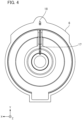
- Fig. 4 is a view illustrating an inner surface side of the housing cover 6 on the load side.
- the rotary electric machine 1 of the present embodiment is an inner rotor type motor, and includes a rotor 2, a shaft 3, and a stator 4.
- the rotor 2, the shaft 3, and the stator 4 are accommodated in a casing including a housing body 5 and housing covers 6. Note that the housing body 5 and the housing covers 6 are all manufactured by casting.
- the rotor 2 is, for example, an interior permanent magnet rotor or a surface permanent magnet rotor.
- a core of the rotor 2 is formed by laminating a plurality of electromagnetic steel sheets or the like in the axial direction.
- the shaft 3 is fitted into the center of the rotor 2 so as to penetrate the core along the rotation axis AX.
- end plates 11a and 11b and rotor covers 12a and 12b are attached to both axial ends of the rotor 2, respectively.
- the shaft 3 has a flange portion 3c and a first tapered region 3a at a portion exposed to an anti-load side (right side in Fig. 2 ) from the core of the rotor 2. Further, the shaft 3 has a second tapered region 3b at a portion exposed from the core of the rotor 2 to a load side (left side in Fig. 2 ).
- the flange portion 3c of the shaft 3 protrudes annularly in the radial direction of the shaft 3 and abuts on the end plate 11a on the anti-load side.
- the first tapered region 3a of the shaft 3 is formed along the axial direction from a surface of the flange portion 3c on the anti-load side, and has a tapered shape reduced in diameter as a distance from the rotor 2 increases and tapered to the anti-load side.
- the second tapered region 3b of the shaft 3 has a tapered shape reduced in diameter as a distance from the rotor 2 increases and tapered to the load side.
- the tapered regions 3a and 3b are examples of a delivery portion.
- the end plates 11a and 11b are ring-shaped members each having a hole opened at the center to allow the shaft 3 to be inserted therethrough and having a smaller diameter than the rotor 2.
- the end plate 11a arranged on the anti-load side is interposed between the flange portion 3c of the shaft 3 and the rotor 2, and is in close contact with an axial end surface (first end surface) of the rotor 2 on the anti-load side.
- the end plate 11b arranged on the load side (left side in Fig. 2 ) is in close contact with an axial end surface (second end surface) of the rotor 2 on the load side.
- the end plates 11a and 11b have a function of pressing the rotor 2 from both sides in the axial direction and holding the core of the rotor 2 made of the laminated steel sheet.
- the rotor cover 12a arranged on the anti-load side covers the end plate 11a and the first end surface of the rotor 2 from the outside, and is fixed to the rotor 2 in close contact with the first end surface.
- the rotor cover 12b arranged on the load side covers the end plate 11b and the second end surface of the rotor 2 from the outside, and is fixed to the rotor 2 in close contact with the second end surface. Note that a detailed configuration of the rotor covers 12a and 12b will be described later.
- the stator 4 has a cylindrical stator core and accommodates the rotor 2 inside with a slight air gap.
- a plurality of slots (not illustrated) are formed along the axial direction on an inner periphery of the stator 4, and a coil is wound around the slots.
- a coil end portion 7 of the coil overhangs from the stator 4 at both axial ends of the stator 4, and has an annular shape in the circumferential direction.
- an attractive force or a repulsive force with respect to a magnetic field of the rotor 2 is generated by sequentially switching the magnetic field of the stator 4 by current control of the coil.
- the rotor 2 and the shaft 3 rotate, whereby the rotary electric machine 1 is driven.
- the coil generates heat by energization.
- a permanent magnet accommodated in the rotor 2 is also heated by electromagnetic induction .
- the housing body 5 of the rotary electric machine 1 is a casing that has a cylindrical space which is opened on both sides in the axial direction.
- the rotor 2 into which the shaft 3 is fitted and the stator 4 are concentrically arranged in the cylindrical space of the housing body 5.
- the stator 4 is fitted to an inner periphery of the housing body 5, and the housing body 5 is attached so as to cover an outer peripheral surface of the stator 4.
- the housing covers 6 are respectively attached to the housing body 5 on both the sides in the axial direction. As a result, openings on both the sides of the housing body 5 are closed by the housing covers 6, respectively. Further, each of the housing covers 6 is provided with a bearing 8, and the shaft 3 is axially supported by the bearings 8 of the housing covers 6 in a rotatable manner. Note that an end of the shaft 3 on the load side penetrates the housing cover 6 and protrudes outward.
- the housing body 5 has an oil supply passage 13 for oil cooling of the coil end portion 7.
- the oil supply passage 13 is an oil passage through which cooling oil flows via an oil cooler and an oil pump (both not illustrated), and is connected to an oil inlet 14 through which the cooling oil is received.
- the oil supply passage 13 is arranged on the upper side of the stator 4 in Fig. 2 .
- the oil supply passage 13 extends in the axial direction in the housing body 5, and both sides thereof are closed by the housing cover 6. Further, ends of the oil supply passage 13 are connected to first flow passages 15 and second flow passages 16, respectively. Note that the first flow passages 15 and the second flow passages 16 are formed on the load side and the anti-load side of the rotary electric machine 1, respectively, and the both have substantially the same configuration.
- the first flow passage 15 is a flow passage branching from the oil supply passage 13 and extending in the circumferential direction, and a plurality of holes are opened downward in the flow passage. Each of the holes of the first flow passage 15 communicates with an internal space of the housing body 5 at a position facing an outer peripheral surface of the coil end portion 7.
- the first flow passage 15 is an example of an oil spreading portion, and has a function of spreading the cooling oil from the oil supply passage 13 to the coil end portion from the upper side.
- the second flow passage 16 is a flow passage for supplying the oil to the bearing 8 via the housing cover 6.
- the second flow passage 16 includes a groove portion 17 formed in the housing cover 6 and a communication hole 18 connecting the oil supply passage 13 and the groove portion 17.
- the groove portion 17 of the second flow passage 16 is formed on an inner surface side of the housing cover 6, and extends vertically along the radial direction of the rotary electric machine 1 from the oil supply passage 13 to the bearing 8 as illustrated in Figs. 2 and 4 .
- the groove portion 17 of the housing cover 6 on the load side is illustrated in Fig. 4
- the groove portion 17 of the housing cover 6 on the anti-load side is also configured similarly to that on the load side.
- the communication hole 18 of the second flow passage 16 is formed to be inclined downward with respect to the axial direction from the end of the oil supply passage 13 in the housing cover 6, and communicates with an upper end of the groove portion 17. As a result, part of the cooling oil from the oil supply passage 13 is supplied to the bearing 8 via the communication hole 18 and the groove portion 17 of the second flow passage 16.
- the vicinity of a bottom surface of the housing body 5 functions as an oil pan in which the oil subjected to heat exchange with the coil end portion 7 is stored.
- the housing body 5 is provided with an oil outlet 19 from which the oil stored in the oil pan is sucked out.
- the oil outlet 19 of the housing body 5 is connected to the oil pump.
- the rotor covers 12a and 12b of the present embodiment can spread the oil supplied to the bearing 8 from the shaft 3 side toward an inner periphery of the coil end portion 7 by centrifugal force.
- the spreading of oil by the rotor covers 12a and 12b will be described.
- the rotor covers 12a and 12b will be also referred to as a rotor cover 12 when common items are described.
- Fig. 5 is a perspective cutaway view of the rotor cover 12.
- Fig. 6 is an enlarged view of the vicinity of the bearing on the load side in Fig. 2 .
- the rotor cover 12 is a disk-shaped member made of metal, and includes a cover body 21, an oil receiving portion 22, and an oil guide portion 23.
- the cover body 21 of the rotor cover 12 has an opening portion through which the shaft 3 can be inserted at the center, and has a disk shape having a dimension corresponding to an outer diameter of the rotor 2.
- a front surface of the cover body 21 faces an inner surface of the housing cover 6, and a back surface of the cover body 21 faces the end plate and the axial end surface of the rotor 2.
- the cover body 21 covers the axial end surface of the rotor 2, thereby functioning to prevent the permanent magnet inserted into the rotor 2 from falling off.
- the oil receiving portion 22 is formed in an annular shape on at outer edge on an inner peripheral side of the cover body 21, and has a function of receiving the oil from the bearing 8 in a clearance formed with respect to an outer peripheral surface of the shaft 3.
- the oil receiving portion 22 protrudes from the front surface of the cover body 21 in the axial direction of the rotary electric machine 1, and has a tapered shape in which an inner peripheral surface increases in diameter from the front surface side toward the back surface side of the rotor cover 12.
- the oil receiving portion 22 is arranged concentrically with a tapered region of the shaft 3 and covers the tapered region from the outside.
- the oil receiving portion 22 of the rotor cover 12b is arranged at a position corresponding to the second tapered region 3b of the shaft 3 as illustrated in Figs. 2 and 6 .
- the oil receiving portion 22 of the rotor cover 12a is arranged at a position corresponding to the first tapered region 3a of the shaft 3 as illustrated in Fig. 2 .
- An inner diameter of the oil receiving portion 22 is set to be larger than an outer diameter of the shaft 3, and the concentric clearance is formed around the shaft 3 with respect to the oil receiving portion 22. Further, the rotor cover 12 is attached to the rotor 2 such that a distal end of the oil receiving portion 22 opposes the bearing 8 in the axial direction.
- At least one oil injection port 24 communicating with the oil receiving portion 22 in the radial direction is formed in the oil receiving portion 22.
- a plurality of the oil injection ports 24 are formed in the oil receiving portion 22 at regular intervals (for example, intervals of 45 degrees) in the circumferential direction. Note that the number and arrangement intervals of the oil injection ports 24 in the oil receiving portion 22 can be appropriately changed.
- the oil guide portion 23 is formed in an annular shape on an outer peripheral side of the front surface of the cover body 21.
- the oil guide portion 23 has an inclined surface having a tapered shape, and has a function of reflecting the oil injected from the oil injection port 24 by the inclined surface and guiding the oil to the coil end portion 7.
- Fig. 5 illustrates the oil guide portion 23 having a shape in which an outer peripheral side of the inclined surface ascends with respect to the front surface of the cover body 21.
- the shape of the oil guide portion 23 is not limited to the above, and for example, an inclined surface having a shape descending from the front surface of the cover body 21 toward the outer peripheral side may be formed.
- the oil stored in the oil pan of the housing body 5 is sucked out from the oil outlet 19 by driving of the oil pump and cooled by the oil cooler.
- the oil cooled by the oil cooler is delivered from the oil inlet 14 to the oil supply passage 13 located on the upper side of the housing body 5.
- the oil supply passage 13 the oil flows to a first side (the anti-load side) and a second side (load side) in the axial direction.
- oil flowing toward the load side of the oil supply passage 13 will be described, and redundant description of oil flowing toward the anti-load side will be omitted.
- the oil flowing to the load side of the oil supply passage 13 branches into the first flow passage 15 and the second flow passage 16 at the end of the oil supply passage 13.
- the oil flowing into the first flow passage 15 is spread to the coil end portion 7 from the upper side, and flows toward the lower side on an outer periphery of the coil end portion 7 from both sides in the counterclockwise direction and the clockwise direction. At this time, the oil in contact with the coil end portion 7 takes heat, whereby the coil end portion 7 is cooled from the outer peripheral side.
- the oil flowing into the second flow passage 16 is guided to the bearing 8 through the communication hole 18 and the groove portion 17 as indicated by arrows in Fig. 6 . Then, the oil passing through the second flow passage 16 is supplied from between the housing cover 6 and the bearing 8 to the bearing 8, and lubrication of the bearing 8 is secured.
- the oil supplied from between the housing cover 6 and the bearing 8 to the bearing 8 reaches the rotor 2 side through, for example, the inside of the bearing 8, and thereafter, flows along the shaft 3 into the clearance formed between the shaft 3 and the oil receiving portion 22 as indicated by arrows in Fig. 6 .
- centrifugal force acts on the oil flowing into the clearance between the shaft 3 and the oil receiving portion 22.
- the oil flowing into the clearance between the shaft 3 and the oil receiving portion 22 is scraped out and delivered radially outward by the tapered region of the shaft 3 protruding in the radial direction.
- the oil flowing into the clearance moves toward the inner peripheral surface of the oil receiving portion 22, and is injected from the oil injection port 24 by the centrifugal force.
- the oil injected from the oil injection port 24 is reflected by the oil guide portion 23 of the cover body 21 and then comes into contact with the inner periphery of the coil end portion 7. Then, the oil in contact with the coil end portion 7 takes heat, whereby the coil end portion 7 is also cooled from the inner peripheral side.
- a position of the oil injection port 24 relative to the coil end portion 7 changes in the circumferential direction as the rotor 2 rotates, the oil from the oil injection port 24 is injected to the entire inner periphery of the coil end portion 7. Further, once the oil from the oil injection port 24 is reflected by the oil guide portion 23, the position (cooling position) where the oil hits on the inner periphery of the coil end portion 7 is adjusted to a desired position according to an angle of the inclined surface. Further, the oil is spread by contact with the oil guide portion 23, and thus, the oil can be brought into contact with a wider range of the inner periphery of the coil end portion 7.
- the permanent magnet accommodated in the rotor 2 is thermally connected to the rotor cover 12 made of metal and in close contact with the axial end surface of the rotor 2.
- the rotor cover 12 is also cooled by the oil when the oil hits the oil guide portion 23 in addition to the contact with the oil at the oil receiving portion 22, and thus, the permanent magnet of the rotor 2 can also be cooled from the axial end side.
- both the oil spread to the coil end portion 7 from the upper side and the oil dropping after being injected to the inner periphery of the coil end portion 7 flow back to the oil pan and are stored therein. Then, the oil in the oil pan is delivered again toward the oil cooler by driving of the oil pump.
- the rotor cover 12 having the oil receiving portion 22 is attached to the rotor 2 in the rotary electric machine 1 of the present embodiment.
- the oil receiving portion 22 forms the concentric clearance with respect to the shaft 3 and receives oil from the bearing 8 through the clearance. Further, the oil guided to the clearance is injected from the oil injection port 24 of the oil receiving portion 22 toward the inner periphery of the coil by the centrifugal force. As a result, the inner peripheral side of the coil can be cooled with the oil in the rotary electric machine 1 of the present embodiment.
- the oil supplied to the bearing 8 is received in the clearance between the oil receiving portion 22 and the shaft 3, and is injected from the oil injection port 24 by the centrifugal force.
- the rotary electric machine of the present invention can also be applied to an oil-cooled generator.
- the configuration example in which the tapered region is formed in the shaft 3 as the delivery portion to oppose the oil receiving portion 22 of the rotor cover 12 has been described in the above-described embodiment, but the configuration of the delivery portion is not limited to the above.
- one or more protrusions may be formed in the circumferential direction of the shaft 3, and the oil from the bearing 8 may be scraped up with the protrusions and delivered to the oil receiving portion 22. Further, the oil from the bearing 8 may be moved to the oil receiving portion 22 by the centrifugal force without forming the taper or the protrusion on the shaft 3 side.
- the configuration example in which the oil from the oil injection port 24 is reflected by the inclined surface of the oil guide portion 23 has been described in the above-described embodiment, but the oil guide portion 23 is not necessarily provided in the rotor cover 12. Further, a plurality of the oil injection ports 24 having different inclinations in the axial direction may be formed in the oil receiving portion 22 to generate a flow for reflecting oil on the oil guide portion 23 and a flow for directly injecting oil to the coil end portion 7.
Landscapes
- Engineering & Computer Science (AREA)
- Power Engineering (AREA)
- Motor Or Generator Cooling System (AREA)
Abstract
Description
- The present invention relates to a rotary electric machine.
- Conventionally, there has been known a rotary electric machine having a cooling structure for cooling that brings cooling oil into contact with a coil end portion of a stator in order to enhance cooling efficiency of a coil wound around a stator core.
- In this type of rotary electric machine having the cooling structure, the cooling oil is injected downward from the upper side of an axial end of the rotary electric machine to the coil end portion. The cooling oil takes heat when coming into contact with the coil end portion, and flows toward an oil pan on the lower side along an outer periphery of the coil end portion.
- In a case where the cooling oil is injected from the upper side of the rotary electric machine, in general, the cooling oil is not directly supplied to the inner peripheral side of the coil end portion, and is only indirectly cooled by oil bounced back after heat exchange, oil mist in a housing, or the like. Therefore, in the above configuration, a cooling effect by the oil on the inner peripheral side of the coil end portion is limited, and it is necessary to increase the overall supply amount of the cooling oil in order to enhance the cooling effect.
- Further, for example, as in
Patent Literatures 1 and 2, there is also proposed a cooling structure in which an oil supply passage is formed inside a rotor shaft along the axial direction, and cooling oil from the rotor shaft is injected to the inner side of a coil by centrifugal force. -
- Patent Literature 1:
JP 2011-10489 A - Patent Literature 2:
JP 2007-159325 A - However, in the cooling structure in which the oil is injected from the inside of the rotor shaft as in
Patent Literatures 1 and 2, it is necessary to sufficiently increase the pressure of the cooling oil with a pump in order to deliver the oil into the shaft, and it is also necessary to provide an oil seal at a portion delivering the oil to the rotating shaft. Therefore, a cost of the cooling structure increases. Further, the rigidity of the rotor shaft may also decrease because the rotor shaft has a hollow structure inPatent Literatures 1 and 2. - The present invention has been made in view of the above circumstances, and provides a rotary electric machine capable of injecting oil to an inner periphery of a coil without supplying the oil into a rotor shaft.
- A rotary electric machine of one aspect of the present invention includes: a rotor; a shaft that penetrates the rotor along a rotation axis and is pivotally supported by a bearing; a stator that has a cylindrical shape, accommodates the rotor inside, and has a coil wound around an inner peripheral side; a rotor cover attached to an axial end surface of the rotor; and a casing having a flow passage for supplying oil to the bearing. The rotor cover has an oil receiving portion that forms a concentric clearance with respect to the shaft and receives the oil from the bearing in the clearance. The oil receiving portion has an injection port for injecting the oil guided to the clearance toward an inner periphery of the coil by centrifugal force.
- In the rotary electric machine of one aspect described above, the shaft may have a delivery portion that protrudes in the radial direction inside the clearance and delivers the oil to the oil receiving portion.
- In the rotary electric machine of one aspect described above, the rotor cover may have an oil guide portion on an outer peripheral side of the oil receiving portion. The oil guide portion may include an inclined surface that reflects the oil injected from the injection port, and adjust a position where the coil is cooled by the oil.
- Further, the rotor cover may be made of metal and cover the axial end surface of the rotor. Further, the axial end surface of the rotor may be cooled by the oil via the oil guide portion of the rotor cover.
- In the rotary electric machine of one aspect described above, the casing may further include: an oil spreading portion that spreads the oil from an upper side of the coil; and an oil supply passage for supplying the oil to the oil spreading portion. Further, the flow passage may supply the oil branching from the oil supply passage.
- According to one aspect of the present invention, the oil can be injected to the inner periphery of the coil without supplying the oil into the rotor shaft.
-
-
Fig. 1 is a perspective view illustrating an example of a rotary electric machine of the present embodiment. -
Fig. 2 is a cross-sectional view taken along line A-A ofFig. 1 . -
Fig. 3 is a front view of the rotary electric machine in a state where a housing cover on a load side is removed. -
Fig. 4 is a view illustrating an inner surface side of the housing cover on the load side. -
Fig. 5 is a perspective cutaway view of a rotor cover. -
Fig. 6 is an enlarged view of the vicinity of a bearing on the load side inFig. 2 . - Hereinafter, an embodiment of the present invention will be described with reference to the drawings.
- In the embodiment, structures and elements other than the main part of the present invention will be described in a simplified or omitted manner in order for easy understanding. Further, the same elements are denoted by the same reference signs in the drawings. Note that shapes, dimensions, and the like of the respective elements illustrated in the drawings are schematically illustrated, and do not indicate actual shapes, dimensions, and the like.
- In the drawings, an XYZ coordinate system is illustrated appropriately as a three-dimensional orthogonal coordinate system. In the XYZ coordinate system, a Z direction is a direction parallel to a rotation axis. An X direction is a direction orthogonal to the Z direction and corresponds to a direction perpendicular to the paper surface of
Fig. 2 . A Y direction is a direction orthogonal to both the X direction and the Z direction, and corresponds to the vertical direction inFig. 2 . Further, the rotation axis of the rotary electric machine is denoted by reference sign AX as necessary in the drawings. Note that, in the following description, the circumferential direction around the rotation axis AX is simply referred to as the circumferential direction, and the radial direction around the rotation axis AX is simply referred to as the radial direction. -
Fig. 1 is a perspective view illustrating an example of a rotary electric machine 1 of the present embodiment.Fig. 2 is a cross-sectional view taken along line A-A inFig. 1 .Fig. 3 is a front view of the rotary electric machine 1 in a state where ahousing cover 6 on a load side is removed.Fig. 4 is a view illustrating an inner surface side of thehousing cover 6 on the load side. - The rotary electric machine 1 of the present embodiment is an inner rotor type motor, and includes a
rotor 2, ashaft 3, and astator 4. Therotor 2, theshaft 3, and thestator 4 are accommodated in a casing including ahousing body 5 and housing covers 6. Note that thehousing body 5 and the housing covers 6 are all manufactured by casting. - The
rotor 2 is, for example, an interior permanent magnet rotor or a surface permanent magnet rotor. A core of therotor 2 is formed by laminating a plurality of electromagnetic steel sheets or the like in the axial direction. Further, theshaft 3 is fitted into the center of therotor 2 so as to penetrate the core along the rotation axis AX. Further,end plates rotor 2, respectively. - The
shaft 3 has aflange portion 3c and a firsttapered region 3a at a portion exposed to an anti-load side (right side inFig. 2 ) from the core of therotor 2. Further, theshaft 3 has a secondtapered region 3b at a portion exposed from the core of therotor 2 to a load side (left side inFig. 2 ). - The
flange portion 3c of theshaft 3 protrudes annularly in the radial direction of theshaft 3 and abuts on theend plate 11a on the anti-load side. Further, the firsttapered region 3a of theshaft 3 is formed along the axial direction from a surface of theflange portion 3c on the anti-load side, and has a tapered shape reduced in diameter as a distance from therotor 2 increases and tapered to the anti-load side. Further, the secondtapered region 3b of theshaft 3 has a tapered shape reduced in diameter as a distance from therotor 2 increases and tapered to the load side. Thetapered regions - The
end plates shaft 3 to be inserted therethrough and having a smaller diameter than therotor 2. Theend plate 11a arranged on the anti-load side is interposed between theflange portion 3c of theshaft 3 and therotor 2, and is in close contact with an axial end surface (first end surface) of therotor 2 on the anti-load side. Further, theend plate 11b arranged on the load side (left side inFig. 2 ) is in close contact with an axial end surface (second end surface) of therotor 2 on the load side. Theend plates rotor 2 from both sides in the axial direction and holding the core of therotor 2 made of the laminated steel sheet. - The
rotor cover 12a arranged on the anti-load side covers theend plate 11a and the first end surface of therotor 2 from the outside, and is fixed to therotor 2 in close contact with the first end surface. Further, therotor cover 12b arranged on the load side covers theend plate 11b and the second end surface of therotor 2 from the outside, and is fixed to therotor 2 in close contact with the second end surface. Note that a detailed configuration of the rotor covers 12a and 12b will be described later. - The
stator 4 has a cylindrical stator core and accommodates therotor 2 inside with a slight air gap. A plurality of slots (not illustrated) are formed along the axial direction on an inner periphery of thestator 4, and a coil is wound around the slots. Acoil end portion 7 of the coil overhangs from thestator 4 at both axial ends of thestator 4, and has an annular shape in the circumferential direction. - In the rotary electric machine 1, an attractive force or a repulsive force with respect to a magnetic field of the
rotor 2 is generated by sequentially switching the magnetic field of thestator 4 by current control of the coil. As a result, therotor 2 and theshaft 3 rotate, whereby the rotary electric machine 1 is driven. At this time, the coil generates heat by energization. Further, a permanent magnet accommodated in therotor 2 is also heated by electromagnetic induction. - The
housing body 5 of the rotary electric machine 1 is a casing that has a cylindrical space which is opened on both sides in the axial direction. Therotor 2 into which theshaft 3 is fitted and thestator 4 are concentrically arranged in the cylindrical space of thehousing body 5. Thestator 4 is fitted to an inner periphery of thehousing body 5, and thehousing body 5 is attached so as to cover an outer peripheral surface of thestator 4. - The housing covers 6 are respectively attached to the
housing body 5 on both the sides in the axial direction. As a result, openings on both the sides of thehousing body 5 are closed by the housing covers 6, respectively. Further, each of the housing covers 6 is provided with abearing 8, and theshaft 3 is axially supported by thebearings 8 of the housing covers 6 in a rotatable manner. Note that an end of theshaft 3 on the load side penetrates thehousing cover 6 and protrudes outward. - Further, the
housing body 5 has anoil supply passage 13 for oil cooling of thecoil end portion 7. Theoil supply passage 13 is an oil passage through which cooling oil flows via an oil cooler and an oil pump (both not illustrated), and is connected to anoil inlet 14 through which the cooling oil is received. Theoil supply passage 13 is arranged on the upper side of thestator 4 inFig. 2 . Theoil supply passage 13 extends in the axial direction in thehousing body 5, and both sides thereof are closed by thehousing cover 6. Further, ends of theoil supply passage 13 are connected tofirst flow passages 15 andsecond flow passages 16, respectively. Note that thefirst flow passages 15 and thesecond flow passages 16 are formed on the load side and the anti-load side of the rotary electric machine 1, respectively, and the both have substantially the same configuration. - The
first flow passage 15 is a flow passage branching from theoil supply passage 13 and extending in the circumferential direction, and a plurality of holes are opened downward in the flow passage. Each of the holes of thefirst flow passage 15 communicates with an internal space of thehousing body 5 at a position facing an outer peripheral surface of thecoil end portion 7. Thefirst flow passage 15 is an example of an oil spreading portion, and has a function of spreading the cooling oil from theoil supply passage 13 to the coil end portion from the upper side. - The
second flow passage 16 is a flow passage for supplying the oil to thebearing 8 via thehousing cover 6. Thesecond flow passage 16 includes agroove portion 17 formed in thehousing cover 6 and acommunication hole 18 connecting theoil supply passage 13 and thegroove portion 17. - The
groove portion 17 of thesecond flow passage 16 is formed on an inner surface side of thehousing cover 6, and extends vertically along the radial direction of the rotary electric machine 1 from theoil supply passage 13 to thebearing 8 as illustrated inFigs. 2 and4 . Although thegroove portion 17 of thehousing cover 6 on the load side is illustrated inFig. 4 , thegroove portion 17 of thehousing cover 6 on the anti-load side is also configured similarly to that on the load side. - The
communication hole 18 of thesecond flow passage 16 is formed to be inclined downward with respect to the axial direction from the end of theoil supply passage 13 in thehousing cover 6, and communicates with an upper end of thegroove portion 17. As a result, part of the cooling oil from theoil supply passage 13 is supplied to thebearing 8 via thecommunication hole 18 and thegroove portion 17 of thesecond flow passage 16. - Further, the vicinity of a bottom surface of the
housing body 5 functions as an oil pan in which the oil subjected to heat exchange with thecoil end portion 7 is stored. Thehousing body 5 is provided with anoil outlet 19 from which the oil stored in the oil pan is sucked out. Theoil outlet 19 of thehousing body 5 is connected to the oil pump. - Further, the rotor covers 12a and 12b of the present embodiment can spread the oil supplied to the
bearing 8 from theshaft 3 side toward an inner periphery of thecoil end portion 7 by centrifugal force. Hereinafter, the spreading of oil by the rotor covers 12a and 12b will be described. Hereinafter, the rotor covers 12a and 12b will be also referred to as arotor cover 12 when common items are described. -
Fig. 5 is a perspective cutaway view of therotor cover 12.Fig. 6 is an enlarged view of the vicinity of the bearing on the load side inFig. 2 . - The
rotor cover 12 is a disk-shaped member made of metal, and includes acover body 21, anoil receiving portion 22, and anoil guide portion 23. Thecover body 21 of therotor cover 12 has an opening portion through which theshaft 3 can be inserted at the center, and has a disk shape having a dimension corresponding to an outer diameter of therotor 2. A front surface of thecover body 21 faces an inner surface of thehousing cover 6, and a back surface of thecover body 21 faces the end plate and the axial end surface of therotor 2. Thecover body 21 covers the axial end surface of therotor 2, thereby functioning to prevent the permanent magnet inserted into therotor 2 from falling off. - The
oil receiving portion 22 is formed in an annular shape on at outer edge on an inner peripheral side of thecover body 21, and has a function of receiving the oil from thebearing 8 in a clearance formed with respect to an outer peripheral surface of theshaft 3. Theoil receiving portion 22 protrudes from the front surface of thecover body 21 in the axial direction of the rotary electric machine 1, and has a tapered shape in which an inner peripheral surface increases in diameter from the front surface side toward the back surface side of therotor cover 12. - The
oil receiving portion 22 is arranged concentrically with a tapered region of theshaft 3 and covers the tapered region from the outside. Theoil receiving portion 22 of therotor cover 12b is arranged at a position corresponding to the secondtapered region 3b of theshaft 3 as illustrated inFigs. 2 and6 . Similarly, theoil receiving portion 22 of therotor cover 12a is arranged at a position corresponding to the firsttapered region 3a of theshaft 3 as illustrated inFig. 2 . - An inner diameter of the
oil receiving portion 22 is set to be larger than an outer diameter of theshaft 3, and the concentric clearance is formed around theshaft 3 with respect to theoil receiving portion 22. Further, therotor cover 12 is attached to therotor 2 such that a distal end of theoil receiving portion 22 opposes thebearing 8 in the axial direction. - Further, at least one
oil injection port 24 communicating with theoil receiving portion 22 in the radial direction is formed in theoil receiving portion 22. For example, a plurality of theoil injection ports 24 are formed in theoil receiving portion 22 at regular intervals (for example, intervals of 45 degrees) in the circumferential direction. Note that the number and arrangement intervals of theoil injection ports 24 in theoil receiving portion 22 can be appropriately changed. - The
oil guide portion 23 is formed in an annular shape on an outer peripheral side of the front surface of thecover body 21. Theoil guide portion 23 has an inclined surface having a tapered shape, and has a function of reflecting the oil injected from theoil injection port 24 by the inclined surface and guiding the oil to thecoil end portion 7.Fig. 5 illustrates theoil guide portion 23 having a shape in which an outer peripheral side of the inclined surface ascends with respect to the front surface of thecover body 21. However, the shape of theoil guide portion 23 is not limited to the above, and for example, an inclined surface having a shape descending from the front surface of thecover body 21 toward the outer peripheral side may be formed. - Hereinafter, a flow of oil in the rotary electric machine 1 of the present embodiment will be described.
- In the rotary electric machine 1, the oil stored in the oil pan of the
housing body 5 is sucked out from theoil outlet 19 by driving of the oil pump and cooled by the oil cooler. The oil cooled by the oil cooler is delivered from theoil inlet 14 to theoil supply passage 13 located on the upper side of thehousing body 5. In theoil supply passage 13, the oil flows to a first side (the anti-load side) and a second side (load side) in the axial direction. In the following description, oil flowing toward the load side of theoil supply passage 13 will be described, and redundant description of oil flowing toward the anti-load side will be omitted. - The oil flowing to the load side of the
oil supply passage 13 branches into thefirst flow passage 15 and thesecond flow passage 16 at the end of theoil supply passage 13. The oil flowing into thefirst flow passage 15 is spread to thecoil end portion 7 from the upper side, and flows toward the lower side on an outer periphery of thecoil end portion 7 from both sides in the counterclockwise direction and the clockwise direction. At this time, the oil in contact with thecoil end portion 7 takes heat, whereby thecoil end portion 7 is cooled from the outer peripheral side. - On the other hand, the oil flowing into the
second flow passage 16 is guided to thebearing 8 through thecommunication hole 18 and thegroove portion 17 as indicated by arrows inFig. 6 . Then, the oil passing through thesecond flow passage 16 is supplied from between thehousing cover 6 and thebearing 8 to thebearing 8, and lubrication of thebearing 8 is secured. - Further, the oil supplied from between the
housing cover 6 and thebearing 8 to thebearing 8 reaches therotor 2 side through, for example, the inside of thebearing 8, and thereafter, flows along theshaft 3 into the clearance formed between theshaft 3 and theoil receiving portion 22 as indicated by arrows inFig. 6 . Here, since therotor 2 and theshaft 3 rotate when the rotary electric machine 1 is driven, centrifugal force acts on the oil flowing into the clearance between theshaft 3 and theoil receiving portion 22. Further, the oil flowing into the clearance between theshaft 3 and theoil receiving portion 22 is scraped out and delivered radially outward by the tapered region of theshaft 3 protruding in the radial direction. - Through the above action, the oil flowing into the clearance moves toward the inner peripheral surface of the
oil receiving portion 22, and is injected from theoil injection port 24 by the centrifugal force. The oil injected from theoil injection port 24 is reflected by theoil guide portion 23 of thecover body 21 and then comes into contact with the inner periphery of thecoil end portion 7. Then, the oil in contact with thecoil end portion 7 takes heat, whereby thecoil end portion 7 is also cooled from the inner peripheral side. - Here, a position of the
oil injection port 24 relative to thecoil end portion 7 changes in the circumferential direction as therotor 2 rotates, the oil from theoil injection port 24 is injected to the entire inner periphery of thecoil end portion 7. Further, once the oil from theoil injection port 24 is reflected by theoil guide portion 23, the position (cooling position) where the oil hits on the inner periphery of thecoil end portion 7 is adjusted to a desired position according to an angle of the inclined surface. Further, the oil is spread by contact with theoil guide portion 23, and thus, the oil can be brought into contact with a wider range of the inner periphery of thecoil end portion 7. - Further, the permanent magnet accommodated in the
rotor 2 is thermally connected to therotor cover 12 made of metal and in close contact with the axial end surface of therotor 2. Therotor cover 12 is also cooled by the oil when the oil hits theoil guide portion 23 in addition to the contact with the oil at theoil receiving portion 22, and thus, the permanent magnet of therotor 2 can also be cooled from the axial end side. - Note that both the oil spread to the
coil end portion 7 from the upper side and the oil dropping after being injected to the inner periphery of thecoil end portion 7 flow back to the oil pan and are stored therein. Then, the oil in the oil pan is delivered again toward the oil cooler by driving of the oil pump. - As described above, the
rotor cover 12 having theoil receiving portion 22 is attached to therotor 2 in the rotary electric machine 1 of the present embodiment. Theoil receiving portion 22 forms the concentric clearance with respect to theshaft 3 and receives oil from thebearing 8 through the clearance. Further, the oil guided to the clearance is injected from theoil injection port 24 of theoil receiving portion 22 toward the inner periphery of the coil by the centrifugal force. As a result, the inner peripheral side of the coil can be cooled with the oil in the rotary electric machine 1 of the present embodiment. - Further, in the configuration of the present embodiment, the oil supplied to the
bearing 8 is received in the clearance between theoil receiving portion 22 and theshaft 3, and is injected from theoil injection port 24 by the centrifugal force. In the present embodiment, it is not necessary to provide an oil flow passage in the shaft, and thus, a cost of a cooling structure can be suppressed, and a decrease in rigidity of the shaft is not caused. - The present invention is not limited to the above-described embodiment, and various improvements and design modifications may be made within the scope not departing from the gist of the present invention.
- Although the configuration example of the motor has been described as an example of the rotary electric machine 1 in the above-described embodiment, the rotary electric machine of the present invention can also be applied to an oil-cooled generator.
- Further, the configuration example in which the tapered region is formed in the
shaft 3 as the delivery portion to oppose theoil receiving portion 22 of therotor cover 12 has been described in the above-described embodiment, but the configuration of the delivery portion is not limited to the above. For example, one or more protrusions may be formed in the circumferential direction of theshaft 3, and the oil from thebearing 8 may be scraped up with the protrusions and delivered to theoil receiving portion 22. Further, the oil from thebearing 8 may be moved to theoil receiving portion 22 by the centrifugal force without forming the taper or the protrusion on theshaft 3 side. - Further, the configuration example in which the oil from the
oil injection port 24 is reflected by the inclined surface of theoil guide portion 23 has been described in the above-described embodiment, but theoil guide portion 23 is not necessarily provided in therotor cover 12. Further, a plurality of theoil injection ports 24 having different inclinations in the axial direction may be formed in theoil receiving portion 22 to generate a flow for reflecting oil on theoil guide portion 23 and a flow for directly injecting oil to thecoil end portion 7. - Further, the embodiment disclosed herein is to be considered as illustrative and not restrictive in all respects. The scope of the present invention is indicated not by the above description but by the claims, and it is intended that meanings equivalent to the claims and all modifications within the scope are included.
-
- 1
- Rotary electric machine
- 2
- Rotor
- 3
- Shaft
- 3a, 3b
- Tapered region
- 4
- Stator
- 5
- Housing body
- 6
- Housing cover
- 7
- Coil end portion
- 8
- Bearing
- 12, 12a, 12b
- Rotor cover
- 13
- Oil supply passage
- 15
- First flow passage
- 16
- Second flow passage
- 17
- Groove portion
- 18
- Communication hole
- 21
- Cover body
- 22
- Oil receiving portion
- 23
- Oil guide portion
- 24
- Oil injection port
Claims (5)
- A rotary electric machine comprising:a rotor;a shaft that penetrates the rotor along a rotation axis and is pivotally supported by a bearing;a stator that has a cylindrical shape, accommodates the rotor inside, and has a coil wound around an inner peripheral side;a rotor cover attached to an axial end surface of the rotor; anda casing having a flow passage for supplying oil to the bearing,wherein the rotor cover has an oil receiving portion that forms a concentric clearance with respect to the shaft and receives the oil from the bearing in the clearance, andthe oil receiving portion has an injection port for injecting the oil guided to the clearance toward an inner periphery of the coil by centrifugal force.
- The rotary electric machine according to claim 1, wherein
the shaft includes a delivery portion that protrudes in a radial direction inside the clearance and delivers the oil to the oil receiving portion. - The rotary electric machine according to claim 1 or 2, whereinthe rotor cover includes an oil guide portion on an outer peripheral side of the oil receiving portion, andthe oil guide portion includes an inclined surface that reflects the oil injected from the injection port, and adjusts a position where the coil is cooled by the oil.
- The rotary electric machine according to any one of claims 1 to 3, whereinthe rotor cover is made of metal and covers the axial end surface of the rotor, andthe axial end surface of the rotor is cooled by the oil via the rotor cover.
- The rotary electric machine according to any one of claims 1 to 4, whereinthe casing further includes: an oil spreading portion that spreads the oil from an upper side of the coil; and an oil supply passage for supplying the oil to the oil spreading portion, andthe flow passage supplies the oil branching from the oil supply passage.
Applications Claiming Priority (2)
| Application Number | Priority Date | Filing Date | Title |
|---|---|---|---|
| JP2021154029A JP7192941B1 (en) | 2021-09-22 | 2021-09-22 | Rotating electric machine |
| PCT/JP2022/031826 WO2023047875A1 (en) | 2021-09-22 | 2022-08-24 | Rotating electrical machine |
Publications (3)
| Publication Number | Publication Date |
|---|---|
| EP4407848A1 true EP4407848A1 (en) | 2024-07-31 |
| EP4407848A4 EP4407848A4 (en) | 2025-03-05 |
| EP4407848B1 EP4407848B1 (en) | 2026-05-06 |
Family
ID=84534588
Family Applications (1)
| Application Number | Title | Priority Date | Filing Date |
|---|---|---|---|
| EP22872631.1A Active EP4407848B1 (en) | 2021-09-22 | 2022-08-24 | Rotary electric machine |
Country Status (5)
| Country | Link |
|---|---|
| US (1) | US12451755B2 (en) |
| EP (1) | EP4407848B1 (en) |
| JP (1) | JP7192941B1 (en) |
| CN (1) | CN118020237A (en) |
| WO (1) | WO2023047875A1 (en) |
Families Citing this family (2)
| Publication number | Priority date | Publication date | Assignee | Title |
|---|---|---|---|---|
| JP7367087B2 (en) * | 2022-01-24 | 2023-10-23 | 本田技研工業株式会社 | rotating electric machine |
| CN120915027B (en) * | 2025-08-07 | 2026-03-13 | 东营合瑞石油技术有限责任公司 | Energy-saving permanent magnet synchronous motor |
Family Cites Families (16)
| Publication number | Priority date | Publication date | Assignee | Title |
|---|---|---|---|---|
| JP2005006429A (en) * | 2003-06-12 | 2005-01-06 | Toyota Motor Corp | Rotor structure in rotating electrical machines |
| JP4858680B2 (en) | 2005-12-07 | 2012-01-18 | シンフォニアテクノロジー株式会社 | Coil cooling mechanism |
| JP4483948B2 (en) * | 2008-01-17 | 2010-06-16 | トヨタ自動車株式会社 | Rotating electric machine |
| JP5197203B2 (en) * | 2008-07-18 | 2013-05-15 | 本田技研工業株式会社 | motor |
| JP4990872B2 (en) * | 2008-11-25 | 2012-08-01 | 本田技研工業株式会社 | Vehicle motor unit |
| US8129874B2 (en) * | 2009-06-17 | 2012-03-06 | Carolyn Lambka | Internal oil cooling via housing end brackets for an electric machine |
| JP5232088B2 (en) | 2009-06-26 | 2013-07-10 | トヨタ自動車株式会社 | Rotor |
| US8482168B2 (en) | 2010-08-25 | 2013-07-09 | Clean Wave Technologies, Inc. | Systems and methods for fluid cooling of electric machines |
| JP2014030284A (en) * | 2012-07-31 | 2014-02-13 | Mitsubishi Motors Corp | Rotary electric machine for vehicle |
| US20150280522A1 (en) * | 2014-03-31 | 2015-10-01 | Caterpillar Inc. | Electric machine having rotor cooling assembly |
| JP7022051B2 (en) * | 2018-12-13 | 2022-02-17 | 本田技研工業株式会社 | Lubrication / cooling structure of electric drive unit |
| EP3672035B1 (en) * | 2018-12-19 | 2022-02-23 | LG Magna e-Powertrain Co., Ltd. | Motor |
| KR102172262B1 (en) | 2019-01-25 | 2020-10-30 | 엘지전자 주식회사 | Electric motor |
| JP7424106B2 (en) * | 2020-02-28 | 2024-01-30 | ニデック株式会社 | drive device |
| CN214069749U (en) * | 2020-11-10 | 2021-08-27 | 上海汽车变速器有限公司 | Oil cooling structure of motor rotor |
| CN113422472A (en) * | 2021-01-25 | 2021-09-21 | 中国第一汽车股份有限公司 | Oil-cooled motor cooling system |
-
2021
- 2021-09-22 JP JP2021154029A patent/JP7192941B1/en active Active
-
2022
- 2022-08-24 WO PCT/JP2022/031826 patent/WO2023047875A1/en not_active Ceased
- 2022-08-24 EP EP22872631.1A patent/EP4407848B1/en active Active
- 2022-08-24 CN CN202280063796.8A patent/CN118020237A/en active Pending
- 2022-08-24 US US18/694,235 patent/US12451755B2/en active Active
Also Published As
| Publication number | Publication date |
|---|---|
| CN118020237A (en) | 2024-05-10 |
| JP7192941B1 (en) | 2022-12-20 |
| JP2023045544A (en) | 2023-04-03 |
| EP4407848B1 (en) | 2026-05-06 |
| WO2023047875A1 (en) | 2023-03-30 |
| EP4407848A4 (en) | 2025-03-05 |
| US20240333081A1 (en) | 2024-10-03 |
| US12451755B2 (en) | 2025-10-21 |
Similar Documents
| Publication | Publication Date | Title |
|---|---|---|
| KR102016863B1 (en) | Rotary electric appliance cooling structure | |
| JP5502421B2 (en) | Rotating electric machine | |
| EP2779366B1 (en) | Electrical machine having cooling features | |
| CN102714438B (en) | Rotors for rotating electrical machines | |
| CN107786017B (en) | Rotor structure of rotating electric machine | |
| EP4311078B1 (en) | Axial flux machine with direct magnet cooling | |
| US12451755B2 (en) | Rotary electric machine with stator and oil injection port | |
| EP3687037A1 (en) | Electric motor | |
| JP2012105487A (en) | Cooling device for electric motor | |
| CN115378168B (en) | Rotor assembly and motor including the same | |
| US10958121B2 (en) | Rotating electrical machine | |
| JP2014230393A (en) | Rotary electric machine | |
| CN113659740A (en) | Stator module, magnetic suspension bearing, motor, compressor and air conditioner | |
| CN111384798B (en) | Rotating electrical machine | |
| WO2020176572A1 (en) | Electric machine with internal cooling passageways | |
| EP4412057B1 (en) | Rotary electrical machine | |
| JP6190910B1 (en) | Rotating electric machine | |
| CN108736603B (en) | Rotating electrical machine | |
| CN110462218B (en) | Centrifugal pump assembly with axial flux motor and method of assembling the same | |
| JP2020018116A (en) | Rotor and rotating electric | |
| JP7459746B2 (en) | fluid machinery | |
| JP2010045894A (en) | Rotary electric machine | |
| JP7468591B1 (en) | Cooling structure for rotating electric machine and rotating electric machine | |
| JP2017204903A (en) | Dynamo-electric machine | |
| JP2025040873A (en) | Rotating Electric Machine |
Legal Events
| Date | Code | Title | Description |
|---|---|---|---|
| STAA | Information on the status of an ep patent application or granted ep patent |
Free format text: STATUS: THE INTERNATIONAL PUBLICATION HAS BEEN MADE |
|
| PUAI | Public reference made under article 153(3) epc to a published international application that has entered the european phase |
Free format text: ORIGINAL CODE: 0009012 |
|
| STAA | Information on the status of an ep patent application or granted ep patent |
Free format text: STATUS: REQUEST FOR EXAMINATION WAS MADE |
|
| 17P | Request for examination filed |
Effective date: 20240321 |
|
| AK | Designated contracting states |
Kind code of ref document: A1 Designated state(s): AL AT BE BG CH CY CZ DE DK EE ES FI FR GB GR HR HU IE IS IT LI LT LU LV MC MK MT NL NO PL PT RO RS SE SI SK SM TR |
|
| DAV | Request for validation of the european patent (deleted) | ||
| DAX | Request for extension of the european patent (deleted) | ||
| A4 | Supplementary search report drawn up and despatched |
Effective date: 20250130 |
|
| RIC1 | Information provided on ipc code assigned before grant |
Ipc: H02K 5/173 20060101ALI20250124BHEP Ipc: H02K 3/24 20060101ALI20250124BHEP Ipc: H02K 1/32 20060101ALI20250124BHEP Ipc: H02K 5/20 20060101ALI20250124BHEP Ipc: H02K 9/19 20060101AFI20250124BHEP |
|
| GRAJ | Information related to disapproval of communication of intention to grant by the applicant or resumption of examination proceedings by the epo deleted |
Free format text: ORIGINAL CODE: EPIDOSDIGR1 |
|
| GRAP | Despatch of communication of intention to grant a patent |
Free format text: ORIGINAL CODE: EPIDOSNIGR1 |
|
| GRAP | Despatch of communication of intention to grant a patent |
Free format text: ORIGINAL CODE: EPIDOSNIGR1 |
|
| STAA | Information on the status of an ep patent application or granted ep patent |
Free format text: STATUS: GRANT OF PATENT IS INTENDED |
|
| INTG | Intention to grant announced |
Effective date: 20251209 |
|
| GRAS | Grant fee paid |
Free format text: ORIGINAL CODE: EPIDOSNIGR3 |
|
| GRAA | (expected) grant |
Free format text: ORIGINAL CODE: 0009210 |
|
| STAA | Information on the status of an ep patent application or granted ep patent |
Free format text: STATUS: THE PATENT HAS BEEN GRANTED |
|
| AK | Designated contracting states |
Kind code of ref document: B1 Designated state(s): AL AT BE BG CH CY CZ DE DK EE ES FI FR GB GR HR HU IE IS IT LI LT LU LV MC MK MT NL NO PL PT RO RS SE SI SK SM TR |
|
| REG | Reference to a national code |
Ref country code: CH Ref legal event code: F10 Free format text: ST27 STATUS EVENT CODE: U-0-0-F10-F00 (AS PROVIDED BY THE NATIONAL OFFICE) Effective date: 20260506 Ref country code: GB Ref legal event code: FG4D |