EP4407823A1 - Spacer - Google Patents
Spacer Download PDFInfo
- Publication number
- EP4407823A1 EP4407823A1 EP23153292.0A EP23153292A EP4407823A1 EP 4407823 A1 EP4407823 A1 EP 4407823A1 EP 23153292 A EP23153292 A EP 23153292A EP 4407823 A1 EP4407823 A1 EP 4407823A1
- Authority
- EP
- European Patent Office
- Prior art keywords
- spacer
- grommet
- wires
- receptacle
- flow channels
- Prior art date
- Legal status (The legal status is an assumption and is not a legal conclusion. Google has not performed a legal analysis and makes no representation as to the accuracy of the status listed.)
- Pending
Links
Images

Classifications
-
- B—PERFORMING OPERATIONS; TRANSPORTING
- B60—VEHICLES IN GENERAL
- B60R—VEHICLES, VEHICLE FITTINGS, OR VEHICLE PARTS, NOT OTHERWISE PROVIDED FOR
- B60R16/00—Electric or fluid circuits specially adapted for vehicles and not otherwise provided for; Arrangement of elements of electric or fluid circuits specially adapted for vehicles and not otherwise provided for
- B60R16/02—Electric or fluid circuits specially adapted for vehicles and not otherwise provided for; Arrangement of elements of electric or fluid circuits specially adapted for vehicles and not otherwise provided for electric constitutive elements
- B60R16/0207—Wire harnesses
- B60R16/0215—Protecting, fastening and routing means therefor
- B60R16/0222—Grommets
-
- H—ELECTRICITY
- H02—GENERATION; CONVERSION OR DISTRIBUTION OF ELECTRIC POWER
- H02G—INSTALLATION OF ELECTRIC CABLES OR LINES, OR OF COMBINED OPTICAL AND ELECTRIC CABLES OR LINES
- H02G3/00—Installations of electric cables or lines or protective tubing therefor in or on buildings, equivalent structures or vehicles
- H02G3/02—Details
-
- H—ELECTRICITY
- H01—ELECTRIC ELEMENTS
- H01B—CABLES; CONDUCTORS; INSULATORS; SELECTION OF MATERIALS FOR THEIR CONDUCTIVE, INSULATING OR DIELECTRIC PROPERTIES
- H01B3/00—Insulators or insulating bodies characterised by the insulating materials; Selection of materials for their insulating or dielectric properties
- H01B3/18—Insulators or insulating bodies characterised by the insulating materials; Selection of materials for their insulating or dielectric properties mainly consisting of organic substances
- H01B3/30—Insulators or insulating bodies characterised by the insulating materials; Selection of materials for their insulating or dielectric properties mainly consisting of organic substances plastics; resins; waxes
- H01B3/302—Polyurethanes or polythiourethanes; Polyurea or polythiourea
-
- H—ELECTRICITY
- H02—GENERATION; CONVERSION OR DISTRIBUTION OF ELECTRIC POWER
- H02G—INSTALLATION OF ELECTRIC CABLES OR LINES, OR OF COMBINED OPTICAL AND ELECTRIC CABLES OR LINES
- H02G1/00—Methods or apparatus specially adapted for installing, maintaining, repairing or dismantling electric cables or lines
-
- H—ELECTRICITY
- H02—GENERATION; CONVERSION OR DISTRIBUTION OF ELECTRIC POWER
- H02G—INSTALLATION OF ELECTRIC CABLES OR LINES, OR OF COMBINED OPTICAL AND ELECTRIC CABLES OR LINES
- H02G3/00—Installations of electric cables or lines or protective tubing therefor in or on buildings, equivalent structures or vehicles
- H02G3/02—Details
- H02G3/04—Protective tubing or conduits, e.g. cable ladders or cable troughs
- H02G3/0462—Tubings, i.e. having a closed section
-
- H—ELECTRICITY
- H02—GENERATION; CONVERSION OR DISTRIBUTION OF ELECTRIC POWER
- H02G—INSTALLATION OF ELECTRIC CABLES OR LINES, OR OF COMBINED OPTICAL AND ELECTRIC CABLES OR LINES
- H02G3/00—Installations of electric cables or lines or protective tubing therefor in or on buildings, equivalent structures or vehicles
- H02G3/22—Installations of cables or lines through walls, floors or ceilings, e.g. into buildings
Definitions
- the present disclosure relates to a spacer configured to position a bundle of wires in a grommet, the spacer comprising a receptacle having a longitudinal axis for positioning a plurality of wires wherein a passage is provided between an outer circumference of the spacer and the receptacle.
- wire harnesses are provided with grommets overmolded on the wire harness.
- spacers may be used.
- wires may be clamped between two mold halves or after overmolding the grommet it may happen that wires are still visible on the grommet surface.
- known spacers may cause damage to the grommet during product life time.
- the present disclosure is directed at a spacer configured to position a bundle of wires in a grommet, said spacer comprising a receptacle having a longitudinal axis for positioning a plurality of wires, with a passage being provided between an outer circumference of the spacer and the receptacle, wherein the spacer is made of a foamed polyurethane, PUR, material.
- a spacer made of PUR material - as compared to plastic material- has advantageous properties, such as a certain compressibility and resiliency, that avoid a transfer of forces from the wire harness to the outer circumferential surface of the grommet thus avoiding stress spots after manufacture or during life time.
- the spacer has the general shape of a disk with a closed circumferential outer surface that is only interrupted by a single opening forming an entry of the passage.
- the wire harness can be centrally located within the spacer by guiding the wires through the entry and the passage into the receptacle.
- the entry of the passage can be closed by slightly compressing the spacer made of PUR material or of a foamed PUR material. Since the harness is centered within the mold, a minimum wall thickness of the grommet surrounding the harness is ensured.
- the receptacle is surrounded by a plurality of flow channels extending through the spacer, wherein the flow channels have a closed circumferential surface.
- the flow channels allow the material of the grommet to flow freely through the spacer to achieve a homogeneous distribution of the grommet material within the mold and to provide an improved stabilization of the harness during injection of grommet material.
- the wire harness is surrounded by grommet material along the length and the circumference of the grommet. Thereby, the wires of the harness are not visible at the outer circumference of the grommet.
- the flow channels have different cross-sections.
- flow channels that are located closer to the longitudinal axis may have a smaller cross-section as compared to flow channels that are located closer to an outer circumference of the spacer.
- the compressibility of the spacer can be varied and adjusted.
- the flow channels are arranged in a pattern of concentric rings with the flow channels of an outer ring having a larger cross-section than the flow channels of an inner ring. This contributes to stabilize the wire harness within the spacer and also within the grommet.
- the spacer comprises a partitioning wall with a zigzag shape along a circumference of the partitioning wall.
- a partitioning wall with a zigzag shape along a circumference of the partitioning wall.
- the spacer has a set of radially inner partitioning walls and a set of radially outer partitioning walls with the radially inner partitioning walls being located between the radially outer partitioning walls.
- the receptacle is located at a center of the spacer with a circumferential wall of the receptacle having the shape of a circular ring.
- the circumferential wall may form a sleeve around the wire harness thereby positioning and stabilizing the wire harness at a center of the mold and of the grommet.
- an axial dimension of the radial partitioning walls is less than an axial dimension of the circumferential wall.
- the axial dimension of the radial partitioning walls amounts to about 50 % or to about 35 % of the axial dimension of the circumferential wall.
- the radial partitioning walls are sprocket-like and serve to stabilize the spacer on the one hand. On the other hand, such partitioning walls improve the flow of grommet material through the spacer during molding of the grommet.
- an outer circumferential surface of the spacer is inclined with respect to the longitudinal axis.
- the outer circumferential surface of the spacer is not oriented in parallel to the longitudinal axis but provides a peak with a maximum diameter.
- the outer circumferential surface of the spacer comprises two partial circumferential surfaces that are both inclined with respect to the longitudinal axis and that include an obtuse angle. Thereby, the outer circumferential surface forms a (circular) peak line that defines a maximum diameter of the spacer.
- the spacer comprises a plurality of concentric walls, wherein the concentric walls are optionally spaced by means of webs. This prevents an unwanted penetration of mold release agent into the grommet material upon manufacturing the grommet.
- the spaced concentric walls provide an obstacle for the liquid release agent that may flow over an outer surface of the spacer.
- the outer circumferential surface of the spacer is provided with bumps serving as distance elements to reduce the visibility of the spacer on the grommet surface.
- the present disclosure is directed at a system comprising a grommet and a spacer, for example a spacer as disclosed above, wherein the spacer is configured to position a bundle of wires in the grommet, the grommet and the spacer are made of PUR material, and the grommet is overmolded onto the harness and the spacer.
- the spacer and the grommet are made of the same type of material or at least of two materials having similar mechanical properties as regards compressibility, flexibility and stiffness, such as PUR materials with different hardness. This prevents the transmission of forces from the wire harness to an outer circumferential surface of the grommet thereby avoiding stress spots or even rupture on an outer surface of the grommet.
- the grommet and the spacer are made of a foamed polyurethane, PUR, material.
- PUR foamed polyurethane
- the PUR material is injected in a mold in a liquid form where it foams (expands) and fills the mold. After curing, the final product is received.
- the present disclosure is also directed at a method of manufacturing a system as described above, the method comprising the steps of molding the spacer, at least partly curing the spacer, inserting wires in a receptacle of the spacer, placing the spacer and the wires in a mold, overmolding the spacer and the wires in the mold to form a grommet, and curing the grommet.
- the spacer may be fully cured before inserting wires in the receptacle.
- a partly curing can be sufficient.
- Fig. 1 depicts a cross-section of a mold 10 for overmolding a grommet (indicated with a dashed line) onto a bundle of wires 12.
- a spacer 16 is provided for positioning the bundle of wires 12 in a cavity 14 of the mold 10 .
- the spacer 16 positions the bundle of wires 12 along a longitudinal axis A.
- grommet material for example foamed polyurethane material
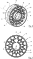
- Fig. 2 depicts a perspective view of the spacer 16 of Fig. 1 .
- the spacer 16 comprises a central receptacle 20 having a longitudinal axis A for receiving and positioning the bundle of wires 12 or a plurality of wires.
- a passage 22 is provided between an outer circumference of the spacer 16 and the receptacle 20.
- the spacer 16 has the general shape of a disk with a closed circumferential outer surface 18 that is only interrupted by a single opening 24 forming an entry of the passage 22.
- the spacer 16 is molded and made of a foamed material, for example of a foamed polyurethane, PUR, material.
- the spacer 16 is integrally formed as a single piece of material.
- An outer circumferential wall 26 of the spacer 16 forming the circumferential outer surface 18 has an axial length that corresponds to an axial length of an inner circumferential wall 28 surrounding and forming the receptacle 20. Between the outer circumferential wall 26 and the inner circumferential wall 28 a circular partitioning wall 30 is provided, said partitioning wall 30 having a zigzag shape along its circumference. An axial length of the partitioning wall 30 corresponds to the axial length of the outer circumferential wall 26 and the inner circumferential wall 28.
- a set of radially inner webs 32 is provided between the inner circumferential wall 28 and the partitioning wall 30 .
- the webs 32 extend in a radial direction and connect to the partitioning wall 30 at the inner peaks of the partitioning wall 30.
- a set of radially outer webs 34 is provided between the partitioning wall 30 and the outer circumferential wall 26, wherein the webs 34 connect to the partitioning wall 30 at radial outer peaks of the partitioning wall 30.
- the radially inner partitioning webs 32 are located between the radially outer webs 34 as seen in a circumferential direction.
- the inner circumferential wall 28, the partitioning wall 30 and the outer circumferential wall 26 form together with the radially inner webs 32 and the radially outer webs 34 a plurality of flow channels 36, 40 that extend through the spacer 16, the flow channels having a closed circumferential surface. It can be seen that the flow channels 36, 40 are arranged in a pattern of (two) concentric rings with flow channels 36 of an outer ring having a larger cross-section than flow channels 40 of an inner ring.
- an axial dimension of the radial webs 32, 34 is less than an axial dimension of the outer circumferential wall 26 (and also of the inner circumferential wall 28 and the partitioning wall 30).
- the axial dimension of the radial webs 32, 34 amounts to about 30-40 % of the axial dimension of the outer circumferential wall 26 and of the inner circumferential wall 28 and the partitioning wall 30.
- the outer circumferential surface 18 of the spacer comprises two partial circumferential surfaces 18A and 18B that are both inclined with respect to the longitudinal axis A and that include an obtuse angle of slightly less than 180°. This allows grommet material to almost completely surround the spacer 16 upon molding the grommet 15.
- the grommet material When filling the mold 10 with grommet material, the grommet material enters the cavity 14, expands (foams) and form a grommet 15.
- a method of manufacturing a bundle of wires provided with a grommet comprises the steps of molding a spacer in a mold separate from the mold 10 and at least partly curing the spacer. This allows potential mold release agent to evaporate. Thereafter, the bundle of wires is inserted in a receptacle of the spacer and the spacer with the inserted wires is placed in the mold 10. Thereafter, the spacer and the wires in the mold are overmolded with grommet material that is cured to form the grommet 15.
- the grommet material and the material of the spacer may be the same material and may comprise a foamed material such as foamed PUR.
Landscapes
- Engineering & Computer Science (AREA)
- Architecture (AREA)
- Civil Engineering (AREA)
- Structural Engineering (AREA)
- Mechanical Engineering (AREA)
- Physics & Mathematics (AREA)
- Spectroscopy & Molecular Physics (AREA)
- Casting Or Compression Moulding Of Plastics Or The Like (AREA)
- Insulating Bodies (AREA)
- Installation Of Indoor Wiring (AREA)
Abstract
A spacer (16) configured to position a bundle of wires (12) in a grommet comprises a receptacle (20) having a longitudinal axis (A) for positioning a plurality of wires (12). Between an outer circumference of the spacer (16) and the receptacle (20) a passage (22) is provided.
Description
- The present disclosure relates to a spacer configured to position a bundle of wires in a grommet, the spacer comprising a receptacle having a longitudinal axis for positioning a plurality of wires wherein a passage is provided between an outer circumference of the spacer and the receptacle.
- For sealing purposes wire harnesses are provided with grommets overmolded on the wire harness. For positioning the wires within the grommet, spacers may be used. However, wires may be clamped between two mold halves or after overmolding the grommet it may happen that wires are still visible on the grommet surface. Furthermore, known spacers may cause damage to the grommet during product life time.
- Accordingly, there is a need to provide a spacer that avoids the above-mentioned problems.
- In one aspect, the present disclosure is directed at a spacer configured to position a bundle of wires in a grommet, said spacer comprising a receptacle having a longitudinal axis for positioning a plurality of wires, with a passage being provided between an outer circumference of the spacer and the receptacle, wherein the spacer is made of a foamed polyurethane, PUR, material.
- By manufacturing the spacer of a PUR material, the risk of damaging the harness by transferring forces via the spacer is reduced. A spacer made of PUR material - as compared to plastic material- has advantageous properties, such as a certain compressibility and resiliency, that avoid a transfer of forces from the wire harness to the outer circumferential surface of the grommet thus avoiding stress spots after manufacture or during life time.
- According to an embodiment, the spacer has the general shape of a disk with a closed circumferential outer surface that is only interrupted by a single opening forming an entry of the passage. In this embodiment the wire harness can be centrally located within the spacer by guiding the wires through the entry and the passage into the receptacle. When placing the wire harness inserted in the spacer in a mold, the entry of the passage can be closed by slightly compressing the spacer made of PUR material or of a foamed PUR material. Since the harness is centered within the mold, a minimum wall thickness of the grommet surrounding the harness is ensured.
- According to an embodiment, the receptacle is surrounded by a plurality of flow channels extending through the spacer, wherein the flow channels have a closed circumferential surface. In this embodiment the flow channels allow the material of the grommet to flow freely through the spacer to achieve a homogeneous distribution of the grommet material within the mold and to provide an improved stabilization of the harness during injection of grommet material. Furthermore, the wire harness is surrounded by grommet material along the length and the circumference of the grommet. Thereby, the wires of the harness are not visible at the outer circumference of the grommet.
- According to an embodiment, the flow channels have different cross-sections. For example, flow channels that are located closer to the longitudinal axis may have a smaller cross-section as compared to flow channels that are located closer to an outer circumference of the spacer. Thereby, the compressibility of the spacer can be varied and adjusted.
- According to an embodiment, the flow channels are arranged in a pattern of concentric rings with the flow channels of an outer ring having a larger cross-section than the flow channels of an inner ring. This contributes to stabilize the wire harness within the spacer and also within the grommet.
- According to an embodiment, the spacer comprises a partitioning wall with a zigzag shape along a circumference of the partitioning wall. Such design allows to use one and the same spacer for different harness diameters and also for different mold diameters. If the spacer is made of foamed PUR material, the receptacle may be expanded to a certain extent when the wire harness is inserted in the receptacle. Simultaneously, the spacer may be compressed when placing the spacer in the mold.
- According to an embodiment, the spacer has a set of radially inner partitioning walls and a set of radially outer partitioning walls with the radially inner partitioning walls being located between the radially outer partitioning walls. This provides a stable design wherein the spacers between the partitioning walls are uniformly varied when the spacer is compressed either towards the longitudinal axis or in the opposite direction.
- According to an embodiment, the receptacle is located at a center of the spacer with a circumferential wall of the receptacle having the shape of a circular ring. In this embodiment, the circumferential wall may form a sleeve around the wire harness thereby positioning and stabilizing the wire harness at a center of the mold and of the grommet.
- According to an embodiment, an axial dimension of the radial partitioning walls is less than an axial dimension of the circumferential wall. For example, the axial dimension of the radial partitioning walls amounts to about 50 % or to about 35 % of the axial dimension of the circumferential wall. In this embodiment, the radial partitioning walls are sprocket-like and serve to stabilize the spacer on the one hand. On the other hand, such partitioning walls improve the flow of grommet material through the spacer during molding of the grommet.
- According to an embodiment, an outer circumferential surface of the spacer is inclined with respect to the longitudinal axis. In this embodiment, the outer circumferential surface of the spacer is not oriented in parallel to the longitudinal axis but provides a peak with a maximum diameter.
- According to an embodiment, the outer circumferential surface of the spacer comprises two partial circumferential surfaces that are both inclined with respect to the longitudinal axis and that include an obtuse angle. Thereby, the outer circumferential surface forms a (circular) peak line that defines a maximum diameter of the spacer.
- According to an embodiment, the spacer comprises a plurality of concentric walls, wherein the concentric walls are optionally spaced by means of webs. This prevents an unwanted penetration of mold release agent into the grommet material upon manufacturing the grommet. The spaced concentric walls provide an obstacle for the liquid release agent that may flow over an outer surface of the spacer.
- According to an embodiment, the outer circumferential surface of the spacer is provided with bumps serving as distance elements to reduce the visibility of the spacer on the grommet surface.
- In another aspect, the present disclosure is directed at a system comprising a grommet and a spacer, for example a spacer as disclosed above, wherein the spacer is configured to position a bundle of wires in the grommet, the grommet and the spacer are made of PUR material, and the grommet is overmolded onto the harness and the spacer.
- In this embodiment, the spacer and the grommet are made of the same type of material or at least of two materials having similar mechanical properties as regards compressibility, flexibility and stiffness, such as PUR materials with different hardness. This prevents the transmission of forces from the wire harness to an outer circumferential surface of the grommet thereby avoiding stress spots or even rupture on an outer surface of the grommet.
- According to an embodiment, the grommet and the spacer are made of a foamed polyurethane, PUR, material. For manufacturing (first) the spacer and (thereafter) the grommet the PUR material is injected in a mold in a liquid form where it foams (expands) and fills the mold. After curing, the final product is received.
- The present disclosure is also directed at a method of manufacturing a system as described above, the method comprising the steps of molding the spacer, at least partly curing the spacer, inserting wires in a receptacle of the spacer, placing the spacer and the wires in a mold, overmolding the spacer and the wires in the mold to form a grommet, and curing the grommet.
- The spacer may be fully cured before inserting wires in the receptacle. When molding the spacer without a release agent, a partly curing can be sufficient.
- Exemplary embodiments and functions of the present disclosure are described herein in conjunction with the following drawings, showing schematically:
- Fig. 1
- a lengthwise cross-section through a mold for manufacturing a grommet;
- Fig. 2
- a perspective view of a spacer; and
- Fig. 3
- a top view of the spacer of
Fig. 1 . -
Fig. 1 depicts a cross-section of amold 10 for overmolding a grommet (indicated with a dashed line) onto a bundle ofwires 12. For positioning the bundle ofwires 12 in acavity 14 of the mold 10 aspacer 16 is provided. Thespacer 16 positions the bundle ofwires 12 along a longitudinal axis A. When thecavity 14 is filled with grommet material, for example foamed polyurethane material, thegrommet 15 is formed around the bundle ofwires 12. -
Fig. 2 depicts a perspective view of thespacer 16 ofFig. 1 . In the embodiment shown, thespacer 16 comprises acentral receptacle 20 having a longitudinal axis A for receiving and positioning the bundle ofwires 12 or a plurality of wires. For inserting thewires 12 into the receptacle 20 apassage 22 is provided between an outer circumference of thespacer 16 and thereceptacle 20. - In the embodiment shown, the
spacer 16 has the general shape of a disk with a closed circumferentialouter surface 18 that is only interrupted by asingle opening 24 forming an entry of thepassage 22. Thespacer 16 is molded and made of a foamed material, for example of a foamed polyurethane, PUR, material. Thespacer 16 is integrally formed as a single piece of material. - An outer
circumferential wall 26 of thespacer 16 forming the circumferentialouter surface 18 has an axial length that corresponds to an axial length of an innercircumferential wall 28 surrounding and forming thereceptacle 20. Between the outercircumferential wall 26 and the inner circumferential wall 28 acircular partitioning wall 30 is provided, saidpartitioning wall 30 having a zigzag shape along its circumference. An axial length of thepartitioning wall 30 corresponds to the axial length of the outercircumferential wall 26 and the innercircumferential wall 28. - Between the inner
circumferential wall 28 and the partitioning wall 30 a set of radiallyinner webs 32 is provided. Thewebs 32 extend in a radial direction and connect to thepartitioning wall 30 at the inner peaks of thepartitioning wall 30. Further, a set of radiallyouter webs 34 is provided between the partitioningwall 30 and the outercircumferential wall 26, wherein thewebs 34 connect to thepartitioning wall 30 at radial outer peaks of thepartitioning wall 30. Thereby, the radiallyinner partitioning webs 32 are located between the radiallyouter webs 34 as seen in a circumferential direction. - As shown in
Fig. 3 , the innercircumferential wall 28, thepartitioning wall 30 and the outercircumferential wall 26 form together with the radiallyinner webs 32 and the radially outer webs 34 a plurality offlow channels spacer 16, the flow channels having a closed circumferential surface. It can be seen that theflow channels flow channels 36 of an outer ring having a larger cross-section thanflow channels 40 of an inner ring. - As shown in
Figs. 1 and2 , an axial dimension of theradial webs circumferential wall 28 and the partitioning wall 30). In the embodiment shown, the axial dimension of theradial webs circumferential wall 26 and of the innercircumferential wall 28 and thepartitioning wall 30. - As shown in
Fig. 2 , the outercircumferential surface 18 of the spacer comprises two partialcircumferential surfaces spacer 16 upon molding thegrommet 15. - When filling the
mold 10 with grommet material, the grommet material enters thecavity 14, expands (foams) and form agrommet 15. - A method of manufacturing a bundle of wires provided with a grommet comprises the steps of molding a spacer in a mold separate from the
mold 10 and at least partly curing the spacer. This allows potential mold release agent to evaporate. Thereafter, the bundle of wires is inserted in a receptacle of the spacer and the spacer with the inserted wires is placed in themold 10. Thereafter, the spacer and the wires in the mold are overmolded with grommet material that is cured to form thegrommet 15. The grommet material and the material of the spacer may be the same material and may comprise a foamed material such as foamed PUR.
Claims (15)
- A spacer (16) configured to position a bundle of wires (12) in a grommet (15), said spacer (16) comprising a receptacle (20) having a longitudinal axis (A) for positioning a plurality of wires (12), with a passage (22) being provided between an outer circumference of the spacer (16) and the receptacle (20), wherein the spacer (16) is made of a foamed polyurethane, PUR, material.
- Spacer according to claim 1, wherein the spacer (16) has the general shape of a disk with a closed circumferential outer surface (18) that is only interrupted by a single opening (24) forming an entry of the passage (22).
- Spacer according to any one of the preceding claims, wherein the receptacle (20) is surrounded by a plurality of flow channels (36, 40) extending through the spacer (16), the flow channels (36, 40) having a closed circumferential surface.
- Spacer according to claim 3, wherein the flow channels (36, 40) have different cross-sections.
- Spacer according to claim 4, wherein the flow channels are arranged in a pattern of concentric rings with the flow channels (36) of an outer ring having a larger cross-section than the flow channels (40) of an inner ring.
- Spacer according to any one of the preceding claims, wherein the spacer (16) comprises a partitioning wall (30) with a zigzag shape along a circumference of the partitioning wall (30).
- Spacer according to any one of the preceding claims, wherein the spacer (16) has a set of radially inner webs (32) and a set of radially outer webs (34) with the radially inner webs (32) being located between the radially outer webs (34).
- Spacer according to any one of the preceding claims, wherein the receptacle (20) is located at center of the spacer (16), with a circumferential wall (28) of the receptacle (20) having the shape of a circular ring.
- Spacer according to 7 and 8, wherein an axial dimension of the radial webs (32, 34) is less than an axial dimension of the circumferential wall (28), and amounts for example to about 50% or about 35 % of the axial dimension of the circumferential wall (28).
- Spacer according to any one of the preceding claims, wherein the spacer (16) comprises a plurality of concentric walls (18, 28, 30).
- Spacer according to claim 10, wherein the concentric walls (18, 28, 30) are spaced by means of webs (32, 34).
- Spacer according to any one of the preceding claims, wherein an outer circumferential surface (18) of the spacer (16) is provided with bumps.
- A system comprising a grommet (15) and a spacer (16), in particular a spacer (16) according to any one of the preceding claims, the spacer (16) being configured to position a bundle of wires (12) in the grommet (15), wherein the grommet (15) and the spacer (16) are made of foamed polyurethane, PUR, material and the grommet (15) is overmolded onto the wires (12) and the spacer (16).
- The system of claim 13, wherein the grommet (15) and the spacer (16) are made of the same PUR material.
- A method of manufacturing a system according to claim 13 or 14, comprising the steps of:- molding the spacer,- at least partly curing the spacer,- inserting wires in a receptacle of the spacer,- placing the spacer and the wires in a mold,- overmolding the spacer and the wires in the mold to form a grommet, and- curing the grommet.
Priority Applications (3)
| Application Number | Priority Date | Filing Date | Title |
|---|---|---|---|
| EP23153292.0A EP4407823A1 (en) | 2023-01-25 | 2023-01-25 | Spacer |
| CN202410098362.2A CN118399274A (en) | 2023-01-25 | 2024-01-24 | Spacing piece |
| US18/422,190 US12565161B2 (en) | 2023-01-25 | 2024-01-25 | Spacer |
Applications Claiming Priority (1)
| Application Number | Priority Date | Filing Date | Title |
|---|---|---|---|
| EP23153292.0A EP4407823A1 (en) | 2023-01-25 | 2023-01-25 | Spacer |
Publications (1)
| Publication Number | Publication Date |
|---|---|
| EP4407823A1 true EP4407823A1 (en) | 2024-07-31 |
Family
ID=85076428
Family Applications (1)
| Application Number | Title | Priority Date | Filing Date |
|---|---|---|---|
| EP23153292.0A Pending EP4407823A1 (en) | 2023-01-25 | 2023-01-25 | Spacer |
Country Status (3)
| Country | Link |
|---|---|
| US (1) | US12565161B2 (en) |
| EP (1) | EP4407823A1 (en) |
| CN (1) | CN118399274A (en) |
Citations (5)
| Publication number | Priority date | Publication date | Assignee | Title |
|---|---|---|---|---|
| DE2317752A1 (en) * | 1973-04-09 | 1974-10-24 | Gervin Mueller | WATERPROOF, INSULATING WALL PIPE FOR ELECTRIC CABLES |
| GB2057595A (en) * | 1979-03-30 | 1981-04-01 | Avon Ind Polymers Bradford On | Seal Assembly |
| FR2602568A1 (en) * | 1986-08-06 | 1988-02-12 | Gaz De France | GUIDING AND PROTECTION DEVICE FOR THE INSTALLATION OF PIPES |
| JPS63254604A (en) * | 1987-04-10 | 1988-10-21 | 日本メクトロン株式会社 | Seal structural body of wire harness for automobile |
| US20170179703A1 (en) * | 2014-09-16 | 2017-06-22 | Yazaki Corporation | Grommet and Method for Manufacturing Same |
Family Cites Families (11)
| Publication number | Priority date | Publication date | Assignee | Title |
|---|---|---|---|---|
| US3092360A (en) * | 1962-02-08 | 1963-06-04 | Boeing Co | Positive locking fairlead for electrical cables |
| US6225562B1 (en) * | 1996-04-26 | 2001-05-01 | Sumitomo Wiring Systems, Ltd. | Sealant for filling grommet, method for sealing a wire harness using the sealant and sealing structure |
| US6552270B1 (en) * | 2002-08-08 | 2003-04-22 | Donald W. Heacox | Harness apparatus |
| US6710249B1 (en) * | 2002-09-13 | 2004-03-23 | Sandra L. Denton | Wire separator |
| DE102010021835B4 (en) * | 2010-05-28 | 2019-05-16 | Airbus Operations Gmbh | Cable holding device for bundle laying of cables, in particular coaxial cables, in an aircraft |
| BR112013029737A2 (en) * | 2011-05-24 | 2017-01-17 | Corning Cable Sys Llc | strain relief device |
| DE102012001408A1 (en) * | 2012-01-25 | 2013-07-25 | Hydac Accessories Gmbh | fastening system |
| US9711956B1 (en) * | 2014-05-21 | 2017-07-18 | Lee D. Welch | Hinged cable guide |
| US9837802B1 (en) * | 2014-09-24 | 2017-12-05 | Cable Glydz, Llc | Cable guide |
| USD860765S1 (en) * | 2018-06-08 | 2019-09-24 | Youhung International View Co., Ltd. | Cable management device |
| US12108558B2 (en) * | 2022-10-25 | 2024-10-01 | Hewlett Packard Enterprise Development Lp | Crosstalk regulator for cables |
-
2023
- 2023-01-25 EP EP23153292.0A patent/EP4407823A1/en active Pending
-
2024
- 2024-01-24 CN CN202410098362.2A patent/CN118399274A/en active Pending
- 2024-01-25 US US18/422,190 patent/US12565161B2/en active Active
Patent Citations (5)
| Publication number | Priority date | Publication date | Assignee | Title |
|---|---|---|---|---|
| DE2317752A1 (en) * | 1973-04-09 | 1974-10-24 | Gervin Mueller | WATERPROOF, INSULATING WALL PIPE FOR ELECTRIC CABLES |
| GB2057595A (en) * | 1979-03-30 | 1981-04-01 | Avon Ind Polymers Bradford On | Seal Assembly |
| FR2602568A1 (en) * | 1986-08-06 | 1988-02-12 | Gaz De France | GUIDING AND PROTECTION DEVICE FOR THE INSTALLATION OF PIPES |
| JPS63254604A (en) * | 1987-04-10 | 1988-10-21 | 日本メクトロン株式会社 | Seal structural body of wire harness for automobile |
| US20170179703A1 (en) * | 2014-09-16 | 2017-06-22 | Yazaki Corporation | Grommet and Method for Manufacturing Same |
Also Published As
| Publication number | Publication date |
|---|---|
| US20240246498A1 (en) | 2024-07-25 |
| US12565161B2 (en) | 2026-03-03 |
| CN118399274A (en) | 2024-07-26 |
Similar Documents
| Publication | Publication Date | Title |
|---|---|---|
| US6225557B1 (en) | Connector casing for coaxial cables | |
| US20170282464A1 (en) | Method for producing an electrical line, tool mould for such a method, and line | |
| US7709739B2 (en) | Elbow connection for multiple-wire electric cable | |
| US5337621A (en) | Cable end fitting retainer and method for making same | |
| US20080017401A1 (en) | Grommet and forming method for the grommet | |
| US20040209025A1 (en) | Cold-shrinkable type rubber sleeve and method of manufacturing the same | |
| US20140174787A1 (en) | Insulator for high-voltage gas insulated switch gear | |
| CA1146049A (en) | Motion transmitting remote control assembly | |
| EP3526867B1 (en) | Cable gland comprising a slip on grommet | |
| US6225953B1 (en) | Method of manufacturing an antenna device for portable telephone | |
| CA2151352C (en) | Composite insulator and its manufacturing method | |
| US6308395B1 (en) | Swivel insert remote control assembly and method of making same | |
| US12565161B2 (en) | Spacer | |
| US12485592B2 (en) | Sealing element | |
| US6317102B1 (en) | Method and tool for manufacturing an antenna unit, and an antenna unit | |
| EP2485337A2 (en) | Coupling unit for lines | |
| US11728071B2 (en) | Cable assembly with bundling arrangement | |
| US20160174697A1 (en) | Mechanical processing tool, and process and equipment for making a mechanical processing tool | |
| EP3103614B1 (en) | Method for producing a tube and moulding die | |
| US6565790B2 (en) | Injection-molding an electrical-connector shell | |
| KR20240011572A (en) | Mandrel molds for chamber manufacturing of hoses for improved assembly | |
| US3263519A (en) | Flexible conduit with molded end fitting | |
| JP7120575B2 (en) | Insert molded product and method for molding insert molded product | |
| CN215750428U (en) | Multi-strand injection molding centering structure | |
| KR102017665B1 (en) | Method for manufacturing cotter pin shaft |
Legal Events
| Date | Code | Title | Description |
|---|---|---|---|
| PUAI | Public reference made under article 153(3) epc to a published international application that has entered the european phase |
Free format text: ORIGINAL CODE: 0009012 |
|
| STAA | Information on the status of an ep patent application or granted ep patent |
Free format text: STATUS: THE APPLICATION HAS BEEN PUBLISHED |
|
| AK | Designated contracting states |
Kind code of ref document: A1 Designated state(s): AL AT BE BG CH CY CZ DE DK EE ES FI FR GB GR HR HU IE IS IT LI LT LU LV MC ME MK MT NL NO PL PT RO RS SE SI SK SM TR |
|
| RAP3 | Party data changed (applicant data changed or rights of an application transferred) |
Owner name: APTIV TECHNOLOGIES AG |
|
| STAA | Information on the status of an ep patent application or granted ep patent |
Free format text: STATUS: REQUEST FOR EXAMINATION WAS MADE |
|
| 17P | Request for examination filed |
Effective date: 20250121 |