EP4407808A1 - Socket, socket connector, contact element and connection assembly - Google Patents
Socket, socket connector, contact element and connection assembly Download PDFInfo
- Publication number
- EP4407808A1 EP4407808A1 EP23305082.2A EP23305082A EP4407808A1 EP 4407808 A1 EP4407808 A1 EP 4407808A1 EP 23305082 A EP23305082 A EP 23305082A EP 4407808 A1 EP4407808 A1 EP 4407808A1
- Authority
- EP
- European Patent Office
- Prior art keywords
- socket
- section
- pin
- pin receptacle
- support ring
- Prior art date
- Legal status (The legal status is an assumption and is not a legal conclusion. Google has not performed a legal analysis and makes no representation as to the accuracy of the status listed.)
- Pending
Links
- 230000013011 mating Effects 0.000 claims abstract description 83
- 239000004020 conductor Substances 0.000 claims abstract description 51
- 230000007704 transition Effects 0.000 claims description 10
- 238000004519 manufacturing process Methods 0.000 description 12
- 230000000087 stabilizing effect Effects 0.000 description 12
- 238000005520 cutting process Methods 0.000 description 4
- 238000011161 development Methods 0.000 description 4
- 230000018109 developmental process Effects 0.000 description 4
- 238000003780 insertion Methods 0.000 description 4
- 230000037431 insertion Effects 0.000 description 4
- 239000000463 material Substances 0.000 description 4
- 239000002184 metal Substances 0.000 description 4
- 238000005452 bending Methods 0.000 description 3
- 238000002788 crimping Methods 0.000 description 3
- 239000012212 insulator Substances 0.000 description 2
- 238000005476 soldering Methods 0.000 description 2
- 238000003466 welding Methods 0.000 description 2
- 230000000295 complement effect Effects 0.000 description 1
- 238000009826 distribution Methods 0.000 description 1
- 239000012777 electrically insulating material Substances 0.000 description 1
- 238000009413 insulation Methods 0.000 description 1
- 230000007246 mechanism Effects 0.000 description 1
- 230000003319 supportive effect Effects 0.000 description 1
Images



Classifications
-
- H—ELECTRICITY
- H01—ELECTRIC ELEMENTS
- H01R—ELECTRICALLY-CONDUCTIVE CONNECTIONS; STRUCTURAL ASSOCIATIONS OF A PLURALITY OF MUTUALLY-INSULATED ELECTRICAL CONNECTING ELEMENTS; COUPLING DEVICES; CURRENT COLLECTORS
- H01R11/00—Individual connecting elements providing two or more spaced connecting locations for conductive members which are, or may be, thereby interconnected, e.g. end pieces for wires or cables supported by the wire or cable and having means for facilitating electrical connection to some other wire, terminal, or conductive member, blocks of binding posts
- H01R11/11—End pieces or tapping pieces for wires, supported by the wire and for facilitating electrical connection to some other wire, terminal or conductive member
- H01R11/28—End pieces consisting of a ferrule or sleeve
-
- H—ELECTRICITY
- H01—ELECTRIC ELEMENTS
- H01R—ELECTRICALLY-CONDUCTIVE CONNECTIONS; STRUCTURAL ASSOCIATIONS OF A PLURALITY OF MUTUALLY-INSULATED ELECTRICAL CONNECTING ELEMENTS; COUPLING DEVICES; CURRENT COLLECTORS
- H01R13/00—Details of coupling devices of the kinds covered by groups H01R12/70 or H01R24/00 - H01R33/00
- H01R13/64—Means for preventing incorrect coupling
-
- H—ELECTRICITY
- H01—ELECTRIC ELEMENTS
- H01R—ELECTRICALLY-CONDUCTIVE CONNECTIONS; STRUCTURAL ASSOCIATIONS OF A PLURALITY OF MUTUALLY-INSULATED ELECTRICAL CONNECTING ELEMENTS; COUPLING DEVICES; CURRENT COLLECTORS
- H01R13/00—Details of coupling devices of the kinds covered by groups H01R12/70 or H01R24/00 - H01R33/00
- H01R13/62—Means for facilitating engagement or disengagement of coupling parts or for holding them in engagement
- H01R13/639—Additional means for holding or locking coupling parts together, after engagement, e.g. separate keylock, retainer strap
-
- H—ELECTRICITY
- H01—ELECTRIC ELEMENTS
- H01R—ELECTRICALLY-CONDUCTIVE CONNECTIONS; STRUCTURAL ASSOCIATIONS OF A PLURALITY OF MUTUALLY-INSULATED ELECTRICAL CONNECTING ELEMENTS; COUPLING DEVICES; CURRENT COLLECTORS
- H01R13/00—Details of coupling devices of the kinds covered by groups H01R12/70 or H01R24/00 - H01R33/00
- H01R13/02—Contact members
-
- H—ELECTRICITY
- H01—ELECTRIC ELEMENTS
- H01R—ELECTRICALLY-CONDUCTIVE CONNECTIONS; STRUCTURAL ASSOCIATIONS OF A PLURALITY OF MUTUALLY-INSULATED ELECTRICAL CONNECTING ELEMENTS; COUPLING DEVICES; CURRENT COLLECTORS
- H01R13/00—Details of coupling devices of the kinds covered by groups H01R12/70 or H01R24/00 - H01R33/00
- H01R13/02—Contact members
- H01R13/10—Sockets for co-operation with pins or blades
- H01R13/11—Resilient sockets
-
- H—ELECTRICITY
- H01—ELECTRIC ELEMENTS
- H01R—ELECTRICALLY-CONDUCTIVE CONNECTIONS; STRUCTURAL ASSOCIATIONS OF A PLURALITY OF MUTUALLY-INSULATED ELECTRICAL CONNECTING ELEMENTS; COUPLING DEVICES; CURRENT COLLECTORS
- H01R13/00—Details of coupling devices of the kinds covered by groups H01R12/70 or H01R24/00 - H01R33/00
- H01R13/62—Means for facilitating engagement or disengagement of coupling parts or for holding them in engagement
- H01R13/629—Additional means for facilitating engagement or disengagement of coupling parts, e.g. aligning or guiding means, levers, gas pressure electrical locking indicators, manufacturing tolerances
-
- H—ELECTRICITY
- H01—ELECTRIC ELEMENTS
- H01R—ELECTRICALLY-CONDUCTIVE CONNECTIONS; STRUCTURAL ASSOCIATIONS OF A PLURALITY OF MUTUALLY-INSULATED ELECTRICAL CONNECTING ELEMENTS; COUPLING DEVICES; CURRENT COLLECTORS
- H01R13/00—Details of coupling devices of the kinds covered by groups H01R12/70 or H01R24/00 - H01R33/00
- H01R13/64—Means for preventing incorrect coupling
- H01R13/642—Means for preventing incorrect coupling by position or shape of contact members
-
- H—ELECTRICITY
- H01—ELECTRIC ELEMENTS
- H01R—ELECTRICALLY-CONDUCTIVE CONNECTIONS; STRUCTURAL ASSOCIATIONS OF A PLURALITY OF MUTUALLY-INSULATED ELECTRICAL CONNECTING ELEMENTS; COUPLING DEVICES; CURRENT COLLECTORS
- H01R13/00—Details of coupling devices of the kinds covered by groups H01R12/70 or H01R24/00 - H01R33/00
- H01R13/02—Contact members
- H01R13/15—Pins, blades or sockets having separate spring member for producing or increasing contact pressure
- H01R13/187—Pins, blades or sockets having separate spring member for producing or increasing contact pressure with spring member in the socket
-
- H—ELECTRICITY
- H01—ELECTRIC ELEMENTS
- H01R—ELECTRICALLY-CONDUCTIVE CONNECTIONS; STRUCTURAL ASSOCIATIONS OF A PLURALITY OF MUTUALLY-INSULATED ELECTRICAL CONNECTING ELEMENTS; COUPLING DEVICES; CURRENT COLLECTORS
- H01R4/00—Electrically-conductive connections between two or more conductive members in direct contact, i.e. touching one another; Means for effecting or maintaining such contact; Electrically-conductive connections having two or more spaced connecting locations for conductors and using contact members penetrating insulation
- H01R4/02—Soldered or welded connections
- H01R4/023—Soldered or welded connections between cables or wires and terminals
-
- H—ELECTRICITY
- H01—ELECTRIC ELEMENTS
- H01R—ELECTRICALLY-CONDUCTIVE CONNECTIONS; STRUCTURAL ASSOCIATIONS OF A PLURALITY OF MUTUALLY-INSULATED ELECTRICAL CONNECTING ELEMENTS; COUPLING DEVICES; CURRENT COLLECTORS
- H01R4/00—Electrically-conductive connections between two or more conductive members in direct contact, i.e. touching one another; Means for effecting or maintaining such contact; Electrically-conductive connections having two or more spaced connecting locations for conductors and using contact members penetrating insulation
- H01R4/02—Soldered or welded connections
- H01R4/029—Welded connections
-
- H—ELECTRICITY
- H01—ELECTRIC ELEMENTS
- H01R—ELECTRICALLY-CONDUCTIVE CONNECTIONS; STRUCTURAL ASSOCIATIONS OF A PLURALITY OF MUTUALLY-INSULATED ELECTRICAL CONNECTING ELEMENTS; COUPLING DEVICES; CURRENT COLLECTORS
- H01R43/00—Apparatus or processes specially adapted for manufacturing, assembling, maintaining, or repairing of line connectors or current collectors or for joining electric conductors
- H01R43/16—Apparatus or processes specially adapted for manufacturing, assembling, maintaining, or repairing of line connectors or current collectors or for joining electric conductors for manufacturing contact members, e.g. by punching and by bending
Definitions
- the invention relates to a socket for a high-voltage socket connector, a socket connector, a contact element for mating with the socket, and a connection assembly.
- the object of the invention is to provide a socket that is easy to manufacture and to assemble, while allowing a mechanically stable contacting of a mating contact element.
- a socket for a high-voltage socket connector comprising a conductor connection section adapted for being connected to a conductor of a cable, and a pin receptacle section adapted for receiving a pin of a mating plug connector along a mating direction, wherein the pin receptacle section is integral with the conductor connection section, and wherein the pin receptacle section comprises at least two free ends that extend in opposite circumferential directions around the mating direction and at least in sections face each other.
- the corresponding socket connector comprises at least one socket according to the invention.
- connection assembly comprises at least one socket and at least one mating contact element.
- the mating contact element is adapted for mating with the socket and is, in particular, pin-shaped.
- the pin receptacle section can comprise at least one first free end that extends along a circumferential direction around the mating direction and a second free end that extends counter to the circumferential direction and at least in sections faces the first free end.
- the first free end and the second free end thus form the two free ends according to the invention.
- the two free ends can at least be in sections located at the same insertion depth measured along the mating direction. In other words, an insertion depth may exist at which the two free ends are present and face each other.
- two end faces can face each other, the two end faces being located on the two different free ends.
- the pin receptacle section comprises at least one open support ring section for radially and axially supporting at least one deflectable contact arm adapted for contacting the pin in a mated state.
- the term arm describes a part that is attached to, and thus immobile, relative to a base part at one end and deflectable at the other, free end opposite the attached end.
- the pin receptacle section can comprise or be a sleeve, i.e. a section that surrounds an inner space around a longitudinal axis, namely the mating direction (or as in the rest of the document a direction parallel to the mating direction).
- the socket can comprise a radially open coding channel adapted to fittingly receive a coding element on the pin along the mating direction.
- Radial means directions that are perpendicular to an axial direction of the longitudinal axis.
- the coding channel extends in the mating direction.
- the coding element has a constant cross section along the mating direction.
- the coding channel then has at least an open cross section corresponding to the cross section of the coding element.
- the open support ring section can extend partially around the axis, which can be parallel to the mating direction.
- a circumferential width of the coding channel is less than 20 %, more preferably less than 10 %, and especially less than or 5 % of a circumferential length of a closed envelope running along the inner cross section of the pin receptacle section.
- the circumferential width of the coding channel is preferably greater than 1 %, more preferably greater than 2 %, and especially greater than or 5 % of the circumferential length of the closed envelope.
- the envelope can be defined as being of minimum length, i.e. a minimum length envelope.
- the coding channel can be open towards an open inner space of the pin receptacle section.
- the open support ring section forms at least part of the coding channel.
- the open support ring section can define or delimit the coding channel. Parts or faces of the open support ring section can form parts or faces of the coding channel. For example, at least one free end of the open support ring section can form a sidewall of the coding channel.
- the at least two free ends partially delimit the coding channel.
- the open support ring section may delimit a coding channel in the form of a circumferential gap.
- the open support ring section is radially open at the coding channel. This can allow an easy assembly.
- the open support ring section can be open perpendicular to the mating direction.
- the coding channel should be adapted to fittingly receive the coding element.
- the coding channel is at least in sections complementary to the coding element.
- An open inner space which can be surrounded, defined and/or delimited by the pin receptacle section, can be next to a coding space, which is surrounded, defined and/or delimited by the coding channel.
- the open inner space and the coding space can be subspaces of a single continuous, preferably integral space.
- the term space should be understood as meaning an open space where no material is present.
- a length of the open support ring section can be greater than 5 %, preferably greater than 10 %, and especially greater than 20 % of a length of the pin receptacle section.
- the length can be less than 80 %, preferably less than 50 %, and especially less than 30 % of the length of the pin receptacle section.
- the lengths are to be measured along the axial or mating direction.
- the socket comprises at least two open support ring sections. This can improve the stability and allow a higher current via two contact arms.
- the two open support ring sections are located opposite each other regarding the mating direction. Again, this leads to higher stability.
- the at least two open support ring sections are interconnected to further improve the stability.
- the two open support ring sections can be connected by a stabilizing bridge extending along the mating direction.
- the stabilizing bridge can extend from one open support ring section to the other open support ring section, in particular without intermediate elements.
- the stabilizing bridge can be integral with at least one open support ring section, preferably with two or more open support ring sections.
- the stabilizing bridge can be straight or extend in a straight manner along the mating direction.
- the stabilizing bridge can be parallel to the mating direction.
- a circumferential width of the stabilizing bridge can be less than 20 %, preferably less than 10 %, and especially less than or 5 % of the circumferential length of the closed envelope running along the inner cross section of the pin receptacle section.
- the circumferential width of the stabilizing bridge is preferably greater than 1 %, more preferably greater than 2 %, and especially greater than or 5 % of the circumferential length of the closed envelope.
- the pin receptacle section can comprise a spring sleeve in order to allow an easy contacting.
- the contact arm can be located on or be a part of the spring sleeve.
- a plurality of contact arms can form the spring sleeve.
- the at least one contact arm is integral with the open support ring section. It can be a section or part of the socket. Such a socket can be easy to manufacture and ensure a safe contacting.
- the spring sleeve can be integral with the pin receptacle section, the at least one open support ring section, and/or the rest of the socket. This can make the manufacturing simple.
- the socket can be monolithic, i.e. one-piece or integral, including the at least one contact arm. This simplifies the design and facilitates the production.
- the open support ring section can extend along the entire length of the pin receptacle section, the length being measured along the mating direction.
- the contact arm can protrude from the open support ring section to allow an easy deflection. Preferably, it protrudes radially inwards to contact the mating contact element. It can protrude from the open support ring section along or counter to the mating direction to reduce the risk of damage.
- the contact arm can be inclined, slanted or transverse to the mating direction
- the at least one contact arm is part of a spring element that is separate from the conductor connection section.
- the spring element can be the spring sleeve.
- At least two opposing stop faces adapted to hold the spring element along and counter to the mating direction can be located in the pin receptacle section, in particular at the at least one open support ring section.
- the stop faces can face counter to and along the mating direction to allow a safe and simple stopping.
- the stop faces can be located on radially inward protruding protrusions.
- the socket is a stamped and/or bent part formed from a sheet, in particular a metal sheet. Stamping here refers to a cutting step.
- the sheet can be rectangular.
- the socket can be made from a rectangular metal sheet by cutting out parts located within the rectangular metal sheet only.
- the corresponding socket has a rectangular outer shape when bent into a planar configuration and viewed from above. Overall, when flattened, the outer shape of the socket can be a flat box or cuboid.
- a ratio of a sheet thickness to the outer diameter of the socket and/or the open support ring section is between 1:10 and 1:4. Such ratio is a good compromise between stability and weight.
- a length of the conductor receptacle section can be equal to a length of the pin receptacle section, the lengths being measured along the mating direction.
- the overall size can thus be kept low.
- the socket is preferably mirror-symmetric.
- the mirror plane may be perpendicular to the mating direction.
- the socket may comprise at least two, preferably at least three, more preferably at least four, and especially at least ten contact arms.
- the contact arms may be arranged behind each other in the circumferential direction and/or behind each other in the mating direction.
- the socket comprises at least two arms with opposing extension directions, in particular substantially along and counter to the mating direction, an embodiment is possible in which no overall force along or counter to the mating direction acts on the pin, when inserted.
- the conductor connection section can, in one embodiment, comprise or be a flat section and/or planar.
- the plane can be parallel to the mating direction to keep the socket flat and allow a space saving mounting of several sockets in one socket connector.
- the conductor connection section may comprise or be a crimp section, thus allowing a safe and easy crimping connection.
- At least one conductor of a cable can be connected to a socket by an ultrasonically welded connection and/or a soldered connection.
- a conductor connection direction of the conductor connection section can be at a right angle to the mating direction.
- Such a socket can be used for a 90-degree connector.
- the pin receptacle section is located entirely in one of the two half-spaces defined by a planar conductor connection section. This can facilitate the production.
- the conductor connection section extends at a right angle to the mating direction away from the pin receptacle section.
- the resulting socket connector can be compact along the mating direction.
- the socket may comprise a transition section between the conductor connection section and the pin receptacle section, the transition section having a lower cross section area than the conductor connection section. This can reduce the weight.
- these cross sections are taken perpendicular to the direction going from the conductor connection section to the pin receptacle section and/or are parallel to the mating direction.
- the transition section can be formed by residual material remaining after at least one unilaterally joined part for example a flap, a prong, or a finger, has been cut and bent to form a part of the pin receptacle section. At least one recess in the transition section may correspond to the unilaterally joined part of the pin receptacle section. Thereby, the weight can be reduced while the pin receptacle section provides sufficient support for the pin.
- at least one of the free ends according to the inventive solution is preferably part of the unilaterally joined part.
- At least two sockets according to the invention are present, wherein the conductor connection sections of at least two sockets are parallel and arranged at an offset greater than an offset of the corresponding pin receptacle sections.
- a preferred mating contact element is pin-shaped and comprises a radially protruding coding element that extends parallel to the mating direction from a tip to a base of the contact element.
- the coding element may protrude radially from a conductive shaft.
- the coding element is adapted to act as a touch protection bar, which can be a part of a touch protection arrangement. This double function in one part simplifies the configuration.
- the coding element is preferably made from an electrically insulating material.
- the shaft can have a cylindrical outer shape, in particular the shape of a circular cylinder. This can result in a good force distribution.
- the inner face of the open support ring section is part cylindrical.
- the socket is adapted for repeated cycles of plugging-in and removing the pin.
- the making of a permanent connection for example by welding, soldering or crimping is not to be covered.
- the coding element preferably allows mating of the plug connector and the socket connector only in a predefined rotational configuration around the mating direction or a direction parallel thereto.
- the pin receptacle section and/or the open support ring section can, in one embodiment, be open on two sides, in particular along and counter to the mating direction. In a different embodiment, the pin receptacle section and/or the open support ring section are only open at one side.
- the open support ring section has a constant clear cross section along the mating direction to allow an easy insertion of the pin.
- the entire open support ring section can have a constant cross section along the mating direction.
- Such an embodiment can be easy to manufacture.
- an outermost location along the mating direction can be part of the open support ring section.
- the open support ring section may form an entrance for the pin.
- the open support ring section is integral with at least one other part, preferably with all other parts of the pin receptacle section. This can result in a weight saving and easy to produce solution.
- contacting used in this description in particular relates to electric contacting, i.e. the making of an electrically conductive connection.
- pin is to be used synonymously with pin-shaped mating contact element.
- the high-voltage socket connector 100 can comprise further elements that are not depicted, in particular at least one insulating housing part or a further contact element.
- the socket connector 100 is adapted for being plugged together with a mating plug connector 200, of which only one contact element 210 in the form of the pin 220 is depicted.
- the pin 220 is inserted into a pin receptacle section 40 of the socket 20 along a mating direction M, which in the depicted embodiments is parallel to an axial direction A of the pin receptacle section 40.
- a shaft 240 of the pin 220 is then in contact with contact arms 70 of the socket connector 100.
- the contact element 210 can be connected for example to a flexible or rigid conductor.
- the contact arms 70 are inclined radially inwards into an inner space 140 of the pin receptacle section 40. They protrude into the path of the pin 220 and are automatically deflected when the pin 220 is inserted.
- the pin receptacle section 40 is formed as a sleeve 49 that surrounds the pin 220 in the mated state.
- the contact arms 70 are arranged behind each other in the circumferential direction C and behind each other in the mating direction M. Further, they extend in opposing directions, namely substantially along and counter to the mating direction M.
- the socket 20 further comprises a conductor connection section 30 configured for making contact to a conductor, for example a wire 120 of a cable 110 (shown in phantom lines in Fig. 2 ) attached to the socket connector 100.
- a conductor for example a wire 120 of a cable 110 (shown in phantom lines in Fig. 2 ) attached to the socket connector 100.
- the conductor connection section 30 is a flat section 31 that is used for making an ultrasonic welding connection with the wire 120.
- different connection mechanisms can be used, for example soldering or crimping.
- the cable 110 extends away from the socket 20 along a conductor connection direction W that is perpendicular to the mating direction M.
- the plane of the flat section 31 is parallel to the mating direction M.
- the pin receptacle section 40 is located completely in one of the two half-spaces that are defined or delimited by the plane of the conductor connection section 30. This reduces the bending steps during the production.
- this plane could be oriented differently, for example by introducing a twisted section between the conductor connection section 30 and the pin recectacle section 40.
- the plane of the flat section 31 could then for example be perpendicular to the mating direction M.
- the conductor connection section 30 extends along an extension direction E, which is at a right angle to the mating direction M away from the pin receptacle section 40. It is located at a side of the pin receptacle section 40.
- the pin receptacle section 40 is integral with the conductor connection section 30.
- the pin receptacle section 40 and the conductor connection section 30 are formed from a single sheet 23, namely a metal sheet, by cutting and bending. If rolled into a flat shape, a piece with a rectangular outer shape when viewed from above results.
- the pin receptacle section 40 comprises at least two free ends 41, 42 extending in opposite circumferential directions around the mating direction M and at least in sections facing each other. Namely, a first free end 41 extends along a circumferential direction C and several second free ends 42 extend counter to the circumferential direction C. The first and the second free ends 41, 42 are at least in sections located at the same insertion depth along the mating direction M.
- the pin receptacle section 40 comprises at least one open support ring section 50 for radially and axially supporting the at least one deflectable contact arm 70.
- a single open support ring section 50 is present, while the embodiment of Figs. 5 and 6 comprises two open support ring sections 50, 51, 52 located on opposite ends of the socket 20.
- the two open support ring sections 50, 51, 52 are integral with and connected via a stabilizing bridge 53 running parallel to the mating direction M.
- a circumferential width 453 of the stabilizing bridge 53 is such that sufficient mechanical support is provided. However, In order to reduce the weight, the circumferential width 453 should not be too big.
- the stabilizing bridge 53 is located at or forms the first free end 41.
- the open support ring sections 50 have a basically constant clear cross section and a basically constant cross section along the mating direction M and thus a cylindrical inner and outer shape.
- the pin receptacle section 40 and the open support ring sections 50 are open along and counter to the mating direction M. Outermost locations along the mating direction M are part of the open support ring sections 50 and form entrances for the pin 220.
- the socket 20 comprises a radially open coding channel 60 adapted to fittingly receive a coding element 260 on the pin 220 along the mating direction M.
- the coding element 260 has a constant cross section along the mating direction M. It is formed as a bar that extends from a tip 230 to a base 250 of the pin 220 and protrudes in a radial direction R perpendicular to the mating direction M away from the shaft 240.
- the coding element 260 is in this example made from an insulator material, for example a plastic.
- the coding channel 60 of the socket 20 extends in the mating direction M or axial direction A and has at each point along the mating direction M a clear cross section that is at least as big as the cross section of the coding element 260.
- a circumferential width 460 of the coding channel 60 should kept small. However, a certain free width is necessary so that the mating coding element 260 can be wide and stable enough.
- the circumferential width 460 of the coding channel 60 can for example be compared to a circumferential length 440 of a closed envelope running along the inner cross section of the pin receptacle section 40. In the depicted embodiments, the ratio is about 1:6 (16.67 %) corresponding to an angle of 60° of the coding channel 60 (of 360° of the closed envelope) when viewed from a central axis of the pin receptacle section 40.
- the coding channel 60 is open towards an open inner space 140 of the pin receptacle section 40.
- a coding space 160 and the open inner space 140 are continuously connected parts of a single open space.
- the open support ring section 50 is radially open at the coding channel 60.
- the open support ring sections 50 form at least a part of the coding channel 60.
- the end faces 46, 47 form parts of the sidewalls of the coding channel 60.
- the socket 20 comprises a transition section 90 between the conductor connection section 30 and the pin receptacle section 30.
- the transition section 90 has a lower cross sectional area than the conductor connection section 40 and the pin receptacle section 30. This cross section is taken perpendicular to a direction S running from the conductor connection section 30 to the pin receptacle section 40. The direction S is thus counter to the conductor connection direction W and the extension direction E.
- the lower cross sectional area is a result of the manufacturing process, in particular, the cutting and bending of unilaterally joined parts for forming the second free ends 42. Openings or recesses in the transition section 90 correspond to the unilaterally joined parts that form parts of the pin receptacle section 40.
- the contact arms 70 are parts of a spring element 80 or spring sleeve 89 that is separate from the conductor connection section 30.
- the contact arms 70 protrude from open base rings 88 of the spring element 80.
- opposing stop faces 43 located on inwardly protruding protrusions 44 are present in the pin receptacle section 40.
- the protrusions 44 are formed by deforming the sheet 23 at the ends of the part that will be the open support ring section 50.
- the contact arms 70 can be integral with the open support ring sections 50.
- the spring sleeve 89 is here integral with the pin receptacle section 40, the open support ring sections 50, and the rest of the socket 20.
- the entire socket 20 is an integral part 21.
- Lengths 550 of the open support ring sections 50 in the second embodiment are such that they provide stability while keeping the overall weight low.
- the ratio of the length 550 to a length 540 of the pin receptacle section 40 is about 15 %.
- the two lengths 550, 540 are about equal.
- the conductor connection section 30 does not protrude over the pin receptacle section 40 along and counter to the mating direction M.
- a length 530 of the conductor connection section 30 equals a length of the pin receptacle section 540, the lengths 530, 540 being measured along the mating direction M.
- a ratio of a sheet thickness 623 to the outer diameter 650 of the open support ring section(s) 50 (which is identical to the outer diameter of the pin receptacle section 40) is approximately 15 %.
- Both embodiments of a socket 20 are mirror-symmetric, with the mirror plane being perpendicular to the mating direction M. This allows the use in different orientations and the plugging in at both open ends. Furthermore, as shown in Fig. 4 , the sockets 20 can be arranged in a connector 100 such that an offset 603 between two parallel conductor connection sections 30 is greater than an offset 604 between the pin receptacle sections 40 of neighboring sockets 20.
- the coding element 260 of the exemplary embodiments shown in the figures is adapted to act as a touch protection bar.
- This bar can be a part of a touch protection arrangement (not shown in detail), by which contacting of the electrically conductive parts of the pin 220 with a finger is made impossible, in the assembled state.
- the touch protection arrangement can for example further comprise a channel-shaped housing part in which the pin is arranged with the touch protection bar / coding element 260 oriented towards the open face of the channel.
Landscapes
- Details Of Connecting Devices For Male And Female Coupling (AREA)
- Connector Housings Or Holding Contact Members (AREA)
Abstract
The invention relates to a socket (20) for a high-voltage socket connector (100), the socket (20) comprising a conductor connection section (30) adapted for being connected to a conductor of a cable, and a pin receptacle section (40) adapted for receiving a pin (220) of a mating plug connector (200) along a mating direction (M), wherein the pin receptacle section (40) is integral with the conductor connection section (30), and wherein the pin receptacle section (40) comprises at least two free ends (41, 42) that extend in opposite circumferential directions around the mating direction (M) and at least in sections face each other. The invention further relates a connection assembly (300) comprising such a socket (20).
Description
- The invention relates to a socket for a high-voltage socket connector, a socket connector, a contact element for mating with the socket, and a connection assembly.
- Previous sockets are difficult to manufacture and to assemble.
- The object of the invention is to provide a socket that is easy to manufacture and to assemble, while allowing a mechanically stable contacting of a mating contact element.
- According to the invention, this is achieved by a socket for a high-voltage socket connector, the socket comprising a conductor connection section adapted for being connected to a conductor of a cable, and a pin receptacle section adapted for receiving a pin of a mating plug connector along a mating direction, wherein the pin receptacle section is integral with the conductor connection section, and wherein the pin receptacle section comprises at least two free ends that extend in opposite circumferential directions around the mating direction and at least in sections face each other.
- The corresponding socket connector comprises at least one socket according to the invention.
- The connection assembly, according to the invention, comprises at least one socket and at least one mating contact element.
- The mating contact element is adapted for mating with the socket and is, in particular, pin-shaped.
- The fact that the conductor connection section and the pin receptacle section are integral facilitates the manufacturing process. In contrast, previous solutions often comprise two or more parts, which in some cases have shapes that are difficult to manufacture and to assemble. The two free ends opposite each other allow making a mechanically stable connection to the pin.
- The solution according to the invention can be further improved by the following developments and advantageous embodiments, which are independent from each other and can be combined arbitrarily, as desired.
- The pin receptacle section can comprise at least one first free end that extends along a circumferential direction around the mating direction and a second free end that extends counter to the circumferential direction and at least in sections faces the first free end. The first free end and the second free end thus form the two free ends according to the invention.
- The two free ends can at least be in sections located at the same insertion depth measured along the mating direction. In other words, an insertion depth may exist at which the two free ends are present and face each other.
- In particular, two end faces can face each other, the two end faces being located on the two different free ends.
- According to one advantageous embodiment, the pin receptacle section comprises at least one open support ring section for radially and axially supporting at least one deflectable contact arm adapted for contacting the pin in a mated state. This can allow an easy contacting of the mating contact element with the contact arm. The term arm describes a part that is attached to, and thus immobile, relative to a base part at one end and deflectable at the other, free end opposite the attached end.
- The pin receptacle section can comprise or be a sleeve, i.e. a section that surrounds an inner space around a longitudinal axis, namely the mating direction (or as in the rest of the document a direction parallel to the mating direction).
- In order to ensure a correct mating position, the socket can comprise a radially open coding channel adapted to fittingly receive a coding element on the pin along the mating direction. Radial here means directions that are perpendicular to an axial direction of the longitudinal axis.
- Preferably, the coding channel extends in the mating direction. According to one embodiment, the coding element has a constant cross section along the mating direction. The coding channel then has at least an open cross section corresponding to the cross section of the coding element.
- The open support ring section can extend partially around the axis, which can be parallel to the mating direction.
- Preferably, a circumferential width of the coding channel is less than 20 %, more preferably less than 10 %, and especially less than or 5 % of a circumferential length of a closed envelope running along the inner cross section of the pin receptacle section. On the other hand, the circumferential width of the coding channel is preferably greater than 1 %, more preferably greater than 2 %, and especially greater than or 5 % of the circumferential length of the closed envelope. The envelope can be defined as being of minimum length, i.e. a minimum length envelope.
- In order to allow a simple configuration, the coding channel can be open towards an open inner space of the pin receptacle section.
- According to one embodiment, the open support ring section forms at least part of the coding channel.
- The open support ring section can define or delimit the coding channel. Parts or faces of the open support ring section can form parts or faces of the coding channel. For example, at least one free end of the open support ring section can form a sidewall of the coding channel.
- Preferably, the at least two free ends partially delimit the coding channel. For example, the open support ring section may delimit a coding channel in the form of a circumferential gap.
- In one development, the open support ring section is radially open at the coding channel. This can allow an easy assembly.
- The open support ring section can be open perpendicular to the mating direction.
- Generally, the coding channel should be adapted to fittingly receive the coding element. In one preferred embodiment, the coding channel is at least in sections complementary to the coding element.
- An open inner space, which can be surrounded, defined and/or delimited by the pin receptacle section, can be next to a coding space, which is surrounded, defined and/or delimited by the coding channel. The open inner space and the coding space can be subspaces of a single continuous, preferably integral space. The term space should be understood as meaning an open space where no material is present.
- A length of the open support ring section can be greater than 5 %, preferably greater than 10 %, and especially greater than 20 % of a length of the pin receptacle section. On the other hand, the length can be less than 80 %, preferably less than 50 %, and especially less than 30 % of the length of the pin receptacle section. The longer the open support ring section is, the more stable the socket will be. However, a shorter open support ring section can reduce the overall weight. The lengths are to be measured along the axial or mating direction.
- In an advantageous embodiment, the socket comprises at least two open support ring sections. This can improve the stability and allow a higher current via two contact arms.
- Preferably, the two open support ring sections are located opposite each other regarding the mating direction. Again, this leads to higher stability.
- According to one development, the at least two open support ring sections are interconnected to further improve the stability.
- For example, the two open support ring sections can be connected by a stabilizing bridge extending along the mating direction. The stabilizing bridge can extend from one open support ring section to the other open support ring section, in particular without intermediate elements.
- The stabilizing bridge can be integral with at least one open support ring section, preferably with two or more open support ring sections.
- To reduce the weight, the stabilizing bridge can be straight or extend in a straight manner along the mating direction. The stabilizing bridge can be parallel to the mating direction.
- In order to keep the weight low, a circumferential width of the stabilizing bridge can be less than 20 %, preferably less than 10 %, and especially less than or 5 % of the circumferential length of the closed envelope running along the inner cross section of the pin receptacle section. On the other hand, in order to provide a stable and safe embodiment, the circumferential width of the stabilizing bridge is preferably greater than 1 %, more preferably greater than 2 %, and especially greater than or 5 % of the circumferential length of the closed envelope.
- The pin receptacle section can comprise a spring sleeve in order to allow an easy contacting. The contact arm can be located on or be a part of the spring sleeve. In particular, a plurality of contact arms can form the spring sleeve.
- According to one advantageous embodiment, the at least one contact arm is integral with the open support ring section. It can be a section or part of the socket. Such a socket can be easy to manufacture and ensure a safe contacting.
- If the contact arm is located on or part of the spring sleeve, the spring sleeve can be integral with the pin receptacle section, the at least one open support ring section, and/or the rest of the socket. This can make the manufacturing simple.
- In particular, the socket can be monolithic, i.e. one-piece or integral, including the at least one contact arm. This simplifies the design and facilitates the production.
- The open support ring section can extend along the entire length of the pin receptacle section, the length being measured along the mating direction.
- The contact arm can protrude from the open support ring section to allow an easy deflection. Preferably, it protrudes radially inwards to contact the mating contact element. It can protrude from the open support ring section along or counter to the mating direction to reduce the risk of damage. The contact arm can be inclined, slanted or transverse to the mating direction
- According to a further advantageous embodiment, the at least one contact arm is part of a spring element that is separate from the conductor connection section. This can, for example, allow a modular design as different contact arms and/or spring elements can be added to the same conductor connection section. The spring element can be the spring sleeve.
- In order to fix such a separate spring element, at least two opposing stop faces adapted to hold the spring element along and counter to the mating direction can be located in the pin receptacle section, in particular at the at least one open support ring section. The stop faces can face counter to and along the mating direction to allow a safe and simple stopping.
- In one development, the stop faces can be located on radially inward protruding protrusions.
- In an embodiment that is easy to produce, the socket is a stamped and/or bent part formed from a sheet, in particular a metal sheet. Stamping here refers to a cutting step.
- To improve the yield and to allow a simple production, the sheet can be rectangular. The socket can be made from a rectangular metal sheet by cutting out parts located within the rectangular metal sheet only. The corresponding socket has a rectangular outer shape when bent into a planar configuration and viewed from above. Overall, when flattened, the outer shape of the socket can be a flat box or cuboid.
- In one preferred embodiment, a ratio of a sheet thickness to the outer diameter of the socket and/or the open support ring section is between 1:10 and 1:4. Such ratio is a good compromise between stability and weight.
- In particular, a length of the conductor receptacle section can be equal to a length of the pin receptacle section, the lengths being measured along the mating direction. The overall size can thus be kept low.
- To facilitate the mounting and the operation, the socket is preferably mirror-symmetric. In particular, the mirror plane may be perpendicular to the mating direction.
- To establish a good connection, the socket may comprise at least two, preferably at least three, more preferably at least four, and especially at least ten contact arms.
- The contact arms may be arranged behind each other in the circumferential direction and/or behind each other in the mating direction.
- If the socket comprises at least two arms with opposing extension directions, in particular substantially along and counter to the mating direction, an embodiment is possible in which no overall force along or counter to the mating direction acts on the pin, when inserted.
- The conductor connection section can, in one embodiment, comprise or be a flat section and/or planar. The plane can be parallel to the mating direction to keep the socket flat and allow a space saving mounting of several sockets in one socket connector.
- The conductor connection section may comprise or be a crimp section, thus allowing a safe and easy crimping connection.
- In addition to, or alternatively, at least one conductor of a cable can be connected to a socket by an ultrasonically welded connection and/or a soldered connection.
- A conductor connection direction of the conductor connection section can be at a right angle to the mating direction. Such a socket can be used for a 90-degree connector.
- In a preferred embodiment, the pin receptacle section is located entirely in one of the two half-spaces defined by a planar conductor connection section. This can facilitate the production.
- Preferably, the conductor connection section extends at a right angle to the mating direction away from the pin receptacle section. The resulting socket connector can be compact along the mating direction.
- The socket may comprise a transition section between the conductor connection section and the pin receptacle section, the transition section having a lower cross section area than the conductor connection section. This can reduce the weight. In particular, these cross sections are taken perpendicular to the direction going from the conductor connection section to the pin receptacle section and/or are parallel to the mating direction.
- The transition section can be formed by residual material remaining after at least one unilaterally joined part for example a flap, a prong, or a finger, has been cut and bent to form a part of the pin receptacle section. At least one recess in the transition section may correspond to the unilaterally joined part of the pin receptacle section. Thereby, the weight can be reduced while the pin receptacle section provides sufficient support for the pin. In particular, at least one of the free ends according to the inventive solution is preferably part of the unilaterally joined part.
- In a preferred embodiment of the socket connector, at least two sockets according to the invention are present, wherein the conductor connection sections of at least two sockets are parallel and arranged at an offset greater than an offset of the corresponding pin receptacle sections. With this solution, the distance between the conductors attached to the sockets can be increased in order to improve the insulation performance and to allow the use of higher voltages.
- A preferred mating contact element is pin-shaped and comprises a radially protruding coding element that extends parallel to the mating direction from a tip to a base of the contact element.
- In particular, the coding element may protrude radially from a conductive shaft.
- According to a preferred embodiment, the coding element is adapted to act as a touch protection bar, which can be a part of a touch protection arrangement. This double function in one part simplifies the configuration. The coding element is preferably made from an electrically insulating material.
- The shaft can have a cylindrical outer shape, in particular the shape of a circular cylinder. This can result in a good force distribution.
- According to one embodiment, the inner face of the open support ring section is part cylindrical.
- Preferably, the socket is adapted for repeated cycles of plugging-in and removing the pin. In contrast thereto, the making of a permanent connection for example by welding, soldering or crimping is not to be covered.
- The coding element preferably allows mating of the plug connector and the socket connector only in a predefined rotational configuration around the mating direction or a direction parallel thereto.
- The pin receptacle section and/or the open support ring section can, in one embodiment, be open on two sides, in particular along and counter to the mating direction. In a different embodiment, the pin receptacle section and/or the open support ring section are only open at one side.
- Preferably, the open support ring section has a constant clear cross section along the mating direction to allow an easy insertion of the pin.
- Similarly, the entire open support ring section can have a constant cross section along the mating direction. Such an embodiment can be easy to manufacture.
- To allow an easy plug-in, an outermost location along the mating direction can be part of the open support ring section.
- The open support ring section may form an entrance for the pin.
- In one embodiment, the open support ring section is integral with at least one other part, preferably with all other parts of the pin receptacle section. This can result in a weight saving and easy to produce solution.
- The term contacting used in this description in particular relates to electric contacting, i.e. the making of an electrically conductive connection.
- The term pin is to be used synonymously with pin-shaped mating contact element.
- The invention will now be described in greater detail and in an exemplary manner using advantageous embodiments and with reference to the drawings. The described embodiments are only possible configurations in which, however, the individual features as described above can be provided independently of one another or can be omitted.
- In the figures:
- Fig. 1
- shows a schematic perspective, partially exploded view of a first embodiment of a socket together with a mating contact element in the form of a pin;
- Fig. 2
- shows a schematic cross sectional top view of the embodiment of
Fig. 1 ; - Fig. 3
- shows a schematic cross sectional front view of the embodiment of
Fig. 1 ; - Fig. 4
- shows a schematic front view of an advantageous arrangement of two sockets according to
Fig. 1 in a socket connector; - Fig. 5
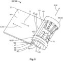
- shows a schematic perspective view of a second embodiment of a socket; and
- Fig. 6
- shows a schematic cross sectional front view of the embodiment of
Fig. 5 . - In the figures, two embodiments of a
socket 20 for a high-voltage socket connector 100 are shown. The high-voltage socket connector 100 can comprise further elements that are not depicted, in particular at least one insulating housing part or a further contact element. - The
socket connector 100 is adapted for being plugged together with amating plug connector 200, of which only onecontact element 210 in the form of thepin 220 is depicted. For making the electrical contact, thepin 220 is inserted into apin receptacle section 40 of thesocket 20 along a mating direction M, which in the depicted embodiments is parallel to an axial direction A of thepin receptacle section 40. Ashaft 240 of thepin 220 is then in contact withcontact arms 70 of thesocket connector 100. At adistal connection section 270, thecontact element 210 can be connected for example to a flexible or rigid conductor. In an operational state, thecontact arms 70 are inclined radially inwards into aninner space 140 of thepin receptacle section 40. They protrude into the path of thepin 220 and are automatically deflected when thepin 220 is inserted. Thepin receptacle section 40 is formed as asleeve 49 that surrounds thepin 220 in the mated state. - The
contact arms 70 are arranged behind each other in the circumferential direction C and behind each other in the mating direction M. Further, they extend in opposing directions, namely substantially along and counter to the mating direction M. - The
socket 20 further comprises aconductor connection section 30 configured for making contact to a conductor, for example awire 120 of a cable 110 (shown in phantom lines inFig. 2 ) attached to thesocket connector 100. In the depicted embodiments, theconductor connection section 30 is aflat section 31 that is used for making an ultrasonic welding connection with thewire 120. In other embodiments, different connection mechanisms can be used, for example soldering or crimping. - The
cable 110 extends away from thesocket 20 along a conductor connection direction W that is perpendicular to the mating direction M. In the exemplary embodiments, the plane of theflat section 31 is parallel to the mating direction M. Advantageously, thepin receptacle section 40 is located completely in one of the two half-spaces that are defined or delimited by the plane of theconductor connection section 30. This reduces the bending steps during the production. - In alternatives, this plane could be oriented differently, for example by introducing a twisted section between the
conductor connection section 30 and thepin recectacle section 40. The plane of theflat section 31 could then for example be perpendicular to the mating direction M. - The
conductor connection section 30 extends along an extension direction E, which is at a right angle to the mating direction M away from thepin receptacle section 40. It is located at a side of thepin receptacle section 40. - The
pin receptacle section 40 is integral with theconductor connection section 30. Thepin receptacle section 40 and theconductor connection section 30 are formed from asingle sheet 23, namely a metal sheet, by cutting and bending. If rolled into a flat shape, a piece with a rectangular outer shape when viewed from above results. - In each of the two cases, the
pin receptacle section 40 comprises at least twofree ends free end 41 extends along a circumferential direction C and several second free ends 42 extend counter to the circumferential direction C. The first and the second free ends 41, 42 are at least in sections located at the same insertion depth along the mating direction M. - Two end faces 46, 47 located on the two
free ends - The
pin receptacle section 40 comprises at least one opensupport ring section 50 for radially and axially supporting the at least onedeflectable contact arm 70. In the embodiment ofFigs. 1 to 4 , a single opensupport ring section 50 is present, while the embodiment ofFigs. 5 and6 comprises two opensupport ring sections 50, 51, 52 located on opposite ends of thesocket 20. In the latter case, the two opensupport ring sections 50, 51, 52 are integral with and connected via a stabilizingbridge 53 running parallel to the mating direction M. Acircumferential width 453 of the stabilizingbridge 53 is such that sufficient mechanical support is provided. However, In order to reduce the weight, thecircumferential width 453 should not be too big. Advantageously, the stabilizingbridge 53 is located at or forms the firstfree end 41. - The open
support ring sections 50 have a basically constant clear cross section and a basically constant cross section along the mating direction M and thus a cylindrical inner and outer shape. - The
pin receptacle section 40 and the opensupport ring sections 50 are open along and counter to the mating direction M. Outermost locations along the mating direction M are part of the opensupport ring sections 50 and form entrances for thepin 220. - The
socket 20 comprises a radiallyopen coding channel 60 adapted to fittingly receive acoding element 260 on thepin 220 along the mating direction M. In the depicted examples, thecoding element 260 has a constant cross section along the mating direction M. It is formed as a bar that extends from atip 230 to abase 250 of thepin 220 and protrudes in a radial direction R perpendicular to the mating direction M away from theshaft 240. Thecoding element 260 is in this example made from an insulator material, for example a plastic. - The
coding channel 60 of thesocket 20 extends in the mating direction M or axial direction A and has at each point along the mating direction M a clear cross section that is at least as big as the cross section of thecoding element 260. - In order to have a good supportive effect from the
pin receptacle section 40, acircumferential width 460 of thecoding channel 60 should kept small. However, a certain free width is necessary so that themating coding element 260 can be wide and stable enough. Thecircumferential width 460 of thecoding channel 60 can for example be compared to acircumferential length 440 of a closed envelope running along the inner cross section of thepin receptacle section 40. In the depicted embodiments, the ratio is about 1:6 (16.67 %) corresponding to an angle of 60° of the coding channel 60 (of 360° of the closed envelope) when viewed from a central axis of thepin receptacle section 40. - The
coding channel 60 is open towards an openinner space 140 of thepin receptacle section 40. Acoding space 160 and the openinner space 140 are continuously connected parts of a single open space. In the depicted embodiments, the opensupport ring section 50 is radially open at thecoding channel 60. - The open
support ring sections 50 form at least a part of thecoding channel 60. The end faces 46, 47 form parts of the sidewalls of thecoding channel 60. - The
socket 20 comprises atransition section 90 between theconductor connection section 30 and thepin receptacle section 30. Thetransition section 90 has a lower cross sectional area than theconductor connection section 40 and thepin receptacle section 30. This cross section is taken perpendicular to a direction S running from theconductor connection section 30 to thepin receptacle section 40. The direction S is thus counter to the conductor connection direction W and the extension direction E. - The lower cross sectional area is a result of the manufacturing process, in particular, the cutting and bending of unilaterally joined parts for forming the second free ends 42. Openings or recesses in the
transition section 90 correspond to the unilaterally joined parts that form parts of thepin receptacle section 40. - In the first embodiment, the
contact arms 70 are parts of aspring element 80 orspring sleeve 89 that is separate from theconductor connection section 30. Thecontact arms 70 protrude from open base rings 88 of thespring element 80. To hold thespring element 80 in place, opposing stop faces 43 located on inwardly protrudingprotrusions 44 are present in thepin receptacle section 40. Theprotrusions 44 are formed by deforming thesheet 23 at the ends of the part that will be the opensupport ring section 50. - As shown in
figs. 5 and6 , thecontact arms 70 can be integral with the opensupport ring sections 50. Thespring sleeve 89 is here integral with thepin receptacle section 40, the opensupport ring sections 50, and the rest of thesocket 20. Theentire socket 20 is anintegral part 21. - Lengths 550 of the open
support ring sections 50 in the second embodiment are such that they provide stability while keeping the overall weight low. In the embodiment offigs 5 and6 , the ratio of the length 550 to a length 540 of thepin receptacle section 40 is about 15 %. In the first embodiment offigs 1 to 4 , the two lengths 550, 540 are about equal. - Further, in both embodiments, the
conductor connection section 30 does not protrude over thepin receptacle section 40 along and counter to the mating direction M. - In both embodiments, a
length 530 of theconductor connection section 30 equals a length of the pin receptacle section 540, thelengths 530, 540 being measured along the mating direction M. - A ratio of a
sheet thickness 623 to theouter diameter 650 of the open support ring section(s) 50 (which is identical to the outer diameter of the pin receptacle section 40) is approximately 15 %. - Both embodiments of a
socket 20 are mirror-symmetric, with the mirror plane being perpendicular to the mating direction M. This allows the use in different orientations and the plugging in at both open ends. Furthermore, as shown inFig. 4 , thesockets 20 can be arranged in aconnector 100 such that an offset 603 between two parallelconductor connection sections 30 is greater than an offset 604 between thepin receptacle sections 40 of neighboringsockets 20. - The
coding element 260 of the exemplary embodiments shown in the figures is adapted to act as a touch protection bar. This bar can be a part of a touch protection arrangement (not shown in detail), by which contacting of the electrically conductive parts of thepin 220 with a finger is made impossible, in the assembled state. The touch protection arrangement can for example further comprise a channel-shaped housing part in which the pin is arranged with the touch protection bar /coding element 260 oriented towards the open face of the channel. -
- 20 socket
- 21 integral part
- 23 sheet
- 30 conductor connection section
- 31 flat section
- 40 pin receptacle section
- 41 first end
- 42 second end
- 43 stop face
- 44 protrusion
- 46 first end face
- 47 second end face
- 49 sleeve
- 50 open support ring section
- 51 first open support ring section
- 52 second open support ring section
- 53 stabilizing bridge
- 60 coding channel
- 61 circumferential gap
- 68 sidewall
- 70 contact arm
- 80 spring element
- 88 open base ring
- 89 spring sleeve
- 90 transition section
- 91 recess
- 100 socket connector
- 110 cable
- 120 wire
- 140 inner space of pin receptacle section
- 160 coding space
- 200 plug connector
- 210 contact element
- 220 pin
- 230 tip
- 240 shaft
- 250 base
- 260 coding element with insulator material
- 270 distal connection section
- 300 connection assembly
- 440 circumferential width of closed envelope
- 453 circumferential width of stabilizing bridge
- 460 circumferential width of coding channel
- 530 length of conductor connection section
- 540 length of pin receptacle section
- 550 length of open support ring section
- 603 offset between conductor connection sections
- 604 offset between pin receptacle sections
- 623 sheet thickness
- 650 outer diameter of the open support ring section
- A axial direction
- C circumferential direction
- E extension direction
- M mating direction
- R radial direction
- S direction
- W conductor connection direction
Claims (15)
- Socket (20) for a high-voltage socket connector (100), the socket (20) comprising a conductor connection section (30) adapted for being connected to a conductor of a cable, and a pin receptacle section (40) adapted for receiving a pin (220) of a mating plug connector (200) along a mating direction (M), wherein the pin receptacle section (40) is integral with the conductor connection section (30), and wherein the pin receptacle section (40) comprises at least two free ends (41, 42) that extend in opposite circumferential directions around the mating direction (M) and at least in sections face each other.
- Socket (20) according to claim 1, wherein the pin receptacle section (40) comprises at least one open support ring section (50) for radially and axially supporting at least one deflectable contact arm (70) adapted for contacting the pin (220) in a mated state.
- Socket (20) according to claim 1 or 2, wherein the socket (20) comprises a radially open coding channel (60) adapted to fittingly receive a coding element (260) on the pin (220) along the mating direction (M).
- Socket (20) according to claim 3, wherein the coding channel (60) is open towards an open inner space (140) of the pin receptacle section (40).
- Socket (20) according to claim 3 or 4, wherein the open support ring section (50) forms at least a part of the coding channel (60).
- Socket (20) according to any one of claims 2 to 5, wherein the socket (20) comprises at least two open support ring sections (50, 51, 52).
- Socket (20) according to any one of claims 2 to 6, wherein the at least one contact arm (70) is integral with the open support ring section (50).
- Socket (20) according to any one of claims 3 to 7, wherein the at least two free ends (41, 42) partially delimit the coding channel (60).
- Socket (20) according to any one of claims 1 to 8, wherein the socket (20) is monolithic.
- Socket (20) according to any one of claims 1 to 9, wherein the at least one contact arm (70) is part of a spring element (80) that is separate from the conductor connection section (30).
- Socket (20) according to any one of claims 1 to 10, wherein the socket (20) is a stamped and/or bent part formed from a sheet (23).
- Socket (20) according to any one of claims 1 to 11, wherein the socket (20) comprises a transition section (90) between the conductor connection section (30) and the pin receptacle section (40), the transition section (90) having a lower cross sectional area than the conductor connection section (30).
- Socket connector (100) comprising at least two sockets (20) according to any one of claims 1 to 12, wherein the conductor connection sections (30) of at least two sockets (20) are parallel and arranged at an offset (603) greater than an offset (604) of the corresponding pin receptacle sections (40).
- Pin-shaped contact element (210) for mating with a socket (20) according to any one of claims 1 to 12, comprising a radially protruding coding element (260) that extends parallel to the mating direction from a tip (230) to a base (250) of the contact element (210).
- Connection assembly (300), comprising a socket (20) according to any one of claims 1 to 12 and a pin-shaped contact element (210) for a plug connector (200).
Priority Applications (3)
| Application Number | Priority Date | Filing Date | Title |
|---|---|---|---|
| EP23305082.2A EP4407808A1 (en) | 2023-01-24 | 2023-01-24 | Socket, socket connector, contact element and connection assembly |
| US18/413,439 US20240250477A1 (en) | 2023-01-24 | 2024-01-16 | Socket, socket connector, contact element and connection assembly |
| CN202410095171.0A CN118399133A (en) | 2023-01-24 | 2024-01-23 | Sockets, socket connectors, contact elements and connection components |
Applications Claiming Priority (1)
| Application Number | Priority Date | Filing Date | Title |
|---|---|---|---|
| EP23305082.2A EP4407808A1 (en) | 2023-01-24 | 2023-01-24 | Socket, socket connector, contact element and connection assembly |
Publications (1)
| Publication Number | Publication Date |
|---|---|
| EP4407808A1 true EP4407808A1 (en) | 2024-07-31 |
Family
ID=85328752
Family Applications (1)
| Application Number | Title | Priority Date | Filing Date |
|---|---|---|---|
| EP23305082.2A Pending EP4407808A1 (en) | 2023-01-24 | 2023-01-24 | Socket, socket connector, contact element and connection assembly |
Country Status (3)
| Country | Link |
|---|---|
| US (1) | US20240250477A1 (en) |
| EP (1) | EP4407808A1 (en) |
| CN (1) | CN118399133A (en) |
Citations (3)
| Publication number | Priority date | Publication date | Assignee | Title |
|---|---|---|---|---|
| US4010996A (en) * | 1976-01-14 | 1977-03-08 | Amp Incorporated | Intrinsic certification assembly technique for wiring components into an electrical apparatus |
| US20190237894A1 (en) * | 2018-01-26 | 2019-08-01 | Tatsuta Electric Wire & Cable Co., Ltd. | Connector Terminal, Connector, and Size Adjustment Device |
| US20220140533A1 (en) * | 2020-10-30 | 2022-05-05 | Tyco Electronics (Shanghai) Co., Ltd. | Unipolar connection terminal for high-voltage connector, and connector device |
Family Cites Families (10)
| Publication number | Priority date | Publication date | Assignee | Title |
|---|---|---|---|---|
| US5588884A (en) * | 1995-09-08 | 1996-12-31 | Packard Hughes Interconnect Company | Stamped and formed contacts for a power connector |
| US5911605A (en) * | 1997-10-16 | 1999-06-15 | Ui Automotive Dearborn, Inc. | Universal terminal connection |
| US6672911B2 (en) * | 2000-09-15 | 2004-01-06 | Alcoa Fujikura Limited | Electrical terminal socket assembly including 90 angled and sealed connectors |
| US6692316B2 (en) * | 2002-04-16 | 2004-02-17 | Delphi Technologies, Inc. | High current terminal blade type sealed connection system |
| CN102414925B (en) * | 2009-07-03 | 2015-05-27 | 矢崎总业株式会社 | Female terminal |
| DE202010003649U1 (en) * | 2010-03-16 | 2010-07-15 | Rosenberger Hochfrequenztechnik Gmbh & Co. Kg | High Power Connectors |
| US8419486B2 (en) * | 2010-12-17 | 2013-04-16 | Tyco Electronics Corporation | Receptacle terminal with a contact spring |
| JP6210965B2 (en) * | 2014-10-31 | 2017-10-11 | 矢崎総業株式会社 | Female terminal |
| DE102016221351A1 (en) * | 2016-10-28 | 2018-05-03 | Te Connectivity Germany Gmbh | Flat contact socket with extension arm |
| KR102923221B1 (en) * | 2020-12-28 | 2026-02-04 | 현대자동차주식회사 | Electrical connection device for vehicle |
-
2023
- 2023-01-24 EP EP23305082.2A patent/EP4407808A1/en active Pending
-
2024
- 2024-01-16 US US18/413,439 patent/US20240250477A1/en active Pending
- 2024-01-23 CN CN202410095171.0A patent/CN118399133A/en active Pending
Patent Citations (3)
| Publication number | Priority date | Publication date | Assignee | Title |
|---|---|---|---|---|
| US4010996A (en) * | 1976-01-14 | 1977-03-08 | Amp Incorporated | Intrinsic certification assembly technique for wiring components into an electrical apparatus |
| US20190237894A1 (en) * | 2018-01-26 | 2019-08-01 | Tatsuta Electric Wire & Cable Co., Ltd. | Connector Terminal, Connector, and Size Adjustment Device |
| US20220140533A1 (en) * | 2020-10-30 | 2022-05-05 | Tyco Electronics (Shanghai) Co., Ltd. | Unipolar connection terminal for high-voltage connector, and connector device |
Also Published As
| Publication number | Publication date |
|---|---|
| CN118399133A (en) | 2024-07-26 |
| US20240250477A1 (en) | 2024-07-25 |
Similar Documents
| Publication | Publication Date | Title |
|---|---|---|
| US11901678B2 (en) | Contact member for electrical connector | |
| US8342891B2 (en) | Electrical connector | |
| EP0572874B1 (en) | Dual thickness blade type electrical terminal | |
| US6439935B2 (en) | Female terminal fitting | |
| EP4539264A2 (en) | Angled subassembly for an angled connector and method of assembling thereof | |
| US20110028034A1 (en) | Hoop material, method of making inner conductor terminal, and coaxial connector | |
| US6086419A (en) | Electrical connector assembly | |
| JP2000195621A (en) | Electric filter connector having multiple ferrite members | |
| EP4535574A2 (en) | Angled subassembly for an angled connector and method of assembling thereof | |
| US11545763B2 (en) | Wire-to-wire connector with splice contact portion | |
| EP0249330A2 (en) | Insulation displacement terminal and connector | |
| JPWO2019044905A1 (en) | Coaxial connector and coaxial connector with coaxial cable | |
| EP1916745B1 (en) | Assembly for connecting the stator windings of an electric motor | |
| US20240250477A1 (en) | Socket, socket connector, contact element and connection assembly | |
| US20240313488A1 (en) | Multi-piece coaxial plug connector with variably configurable interface geometry | |
| US12500366B2 (en) | Electrical plug connector and method for assembling an electrical plug connector | |
| US20040224575A1 (en) | Low insertion force electrical socket contact | |
| US6065987A (en) | Electrical terminal | |
| EP3982494A2 (en) | Cable harness assembly with a shielded twisted pair cable | |
| US12555957B2 (en) | Electric connector assembly, high-voltage terminal and method for assembling | |
| CN121566188A (en) | Connector | |
| JPH0597065U (en) | Electrical contact and electrical connector using the same | |
| HK40084400A (en) | Wire-to-wire connector with splice contact portion | |
| EP0986140B1 (en) | Electrical female terminal | |
| CN110323605A (en) | Electric push-pull connector and its contact |
Legal Events
| Date | Code | Title | Description |
|---|---|---|---|
| PUAI | Public reference made under article 153(3) epc to a published international application that has entered the european phase |
Free format text: ORIGINAL CODE: 0009012 |
|
| STAA | Information on the status of an ep patent application or granted ep patent |
Free format text: STATUS: THE APPLICATION HAS BEEN PUBLISHED |
|
| AK | Designated contracting states |
Kind code of ref document: A1 Designated state(s): AL AT BE BG CH CY CZ DE DK EE ES FI FR GB GR HR HU IE IS IT LI LT LU LV MC ME MK MT NL NO PL PT RO RS SE SI SK SM TR |
|
| RAP1 | Party data changed (applicant data changed or rights of an application transferred) |
Owner name: TE CONNECTIVITY SOLUTIONS GMBH |
|
| STAA | Information on the status of an ep patent application or granted ep patent |
Free format text: STATUS: REQUEST FOR EXAMINATION WAS MADE |
|
| 17P | Request for examination filed |
Effective date: 20250114 |