EP4407807A1 - Connector assembly - Google Patents
Connector assembly Download PDFInfo
- Publication number
- EP4407807A1 EP4407807A1 EP23209792.3A EP23209792A EP4407807A1 EP 4407807 A1 EP4407807 A1 EP 4407807A1 EP 23209792 A EP23209792 A EP 23209792A EP 4407807 A1 EP4407807 A1 EP 4407807A1
- Authority
- EP
- European Patent Office
- Prior art keywords
- contact
- connector
- insulator
- spring member
- rotational
- Prior art date
- Legal status (The legal status is an assumption and is not a legal conclusion. Google has not performed a legal analysis and makes no representation as to the accuracy of the status listed.)
- Granted
Links
Images









Classifications
-
- H—ELECTRICITY
- H01—ELECTRIC ELEMENTS
- H01R—ELECTRICALLY-CONDUCTIVE CONNECTIONS; STRUCTURAL ASSOCIATIONS OF A PLURALITY OF MUTUALLY-INSULATED ELECTRICAL CONNECTING ELEMENTS; COUPLING DEVICES; CURRENT COLLECTORS
- H01R13/00—Details of coupling devices of the kinds covered by groups H01R12/70 or H01R24/00 - H01R33/00
- H01R13/62—Means for facilitating engagement or disengagement of coupling parts or for holding them in engagement
- H01R13/629—Additional means for facilitating engagement or disengagement of coupling parts, e.g. aligning or guiding means, levers, gas pressure electrical locking indicators, manufacturing tolerances
- H01R13/62933—Comprising exclusively pivoting lever
- H01R13/62938—Pivoting lever comprising own camming means
-
- H—ELECTRICITY
- H01—ELECTRIC ELEMENTS
- H01R—ELECTRICALLY-CONDUCTIVE CONNECTIONS; STRUCTURAL ASSOCIATIONS OF A PLURALITY OF MUTUALLY-INSULATED ELECTRICAL CONNECTING ELEMENTS; COUPLING DEVICES; CURRENT COLLECTORS
- H01R13/00—Details of coupling devices of the kinds covered by groups H01R12/70 or H01R24/00 - H01R33/00
- H01R13/62—Means for facilitating engagement or disengagement of coupling parts or for holding them in engagement
- H01R13/639—Additional means for holding or locking coupling parts together, after engagement, e.g. separate keylock, retainer strap
-
- H—ELECTRICITY
- H01—ELECTRIC ELEMENTS
- H01R—ELECTRICALLY-CONDUCTIVE CONNECTIONS; STRUCTURAL ASSOCIATIONS OF A PLURALITY OF MUTUALLY-INSULATED ELECTRICAL CONNECTING ELEMENTS; COUPLING DEVICES; CURRENT COLLECTORS
- H01R13/00—Details of coupling devices of the kinds covered by groups H01R12/70 or H01R24/00 - H01R33/00
- H01R13/02—Contact members
- H01R13/10—Sockets for co-operation with pins or blades
- H01R13/11—Resilient sockets
- H01R13/113—Resilient sockets co-operating with pins or blades having a rectangular transverse section
-
- H—ELECTRICITY
- H01—ELECTRIC ELEMENTS
- H01R—ELECTRICALLY-CONDUCTIVE CONNECTIONS; STRUCTURAL ASSOCIATIONS OF A PLURALITY OF MUTUALLY-INSULATED ELECTRICAL CONNECTING ELEMENTS; COUPLING DEVICES; CURRENT COLLECTORS
- H01R13/00—Details of coupling devices of the kinds covered by groups H01R12/70 or H01R24/00 - H01R33/00
- H01R13/02—Contact members
- H01R13/193—Means for increasing contact pressure at the end of engagement of coupling part, e.g. zero insertion force or no friction
-
- H—ELECTRICITY
- H01—ELECTRIC ELEMENTS
- H01R—ELECTRICALLY-CONDUCTIVE CONNECTIONS; STRUCTURAL ASSOCIATIONS OF A PLURALITY OF MUTUALLY-INSULATED ELECTRICAL CONNECTING ELEMENTS; COUPLING DEVICES; CURRENT COLLECTORS
- H01R4/00—Electrically-conductive connections between two or more conductive members in direct contact, i.e. touching one another; Means for effecting or maintaining such contact; Electrically-conductive connections having two or more spaced connecting locations for conductors and using contact members penetrating insulation
- H01R4/28—Clamped connections, spring connections
- H01R4/50—Clamped connections, spring connections utilising a cam, wedge, cone or ball also combined with a screw
- H01R4/5008—Clamped connections, spring connections utilising a cam, wedge, cone or ball also combined with a screw using rotatable cam
Definitions
- the present invention relates to a connector assembly, particularly to a connector assembly in which a fitting operation between a first connector and a second connector is performed by rotating a lever member.
- JP 2018-152265 A discloses a connector assembly comprising a first connector 1 and a second connector 2 to be fitted to the first connector 1 along a fitting direction D1, as shown in FIG. 44 .
- a first housing 1A of the first connector 1 is provided with a protrusion 1B protruding in a direction perpendicular to the fitting direction D, and a lever member 3 is rotatably attached to the outside of a second housing 2A of the second connector 2 with a rotation fulcrum portion 2B as a fulcrum.
- a guide groove (not shown) is formed to face an outer lateral surface of the second housing 2A.
- the second connector 2 is brought close to the first connector 1 along the fitting direction D, the protrusion 1B of the first connector 1 is inserted into the guide groove of the lever member 3, and in this state, the lever member 3 is rotated, whereby the first connector 1 and the second connector 2 are fitted together.
- first contacts 1C disposed inside the first housing 1A are electrically connected to second contacts 2D inserted in contact insertion ports 2C of the second connector 2 as shown in FIG. 45 .
- the second contacts 2D are connected to ends of electric wires 4, and for instance, when the first connector 1 is mounted on an electric device which is not shown, electric current can flow to the electric device through the electric wires 4.
- the electric wires 4 connected to the second contacts 2D need to have a larger thickness as electric current increases.
- the electric device when, for instance, the electric device is disposed in an environment where the electric device receives an external force such as vibration, e.g., mounted on a vehicle, the external force would be transmitted via the thick electric wires 4 to the points of contact between the first contacts 1C and the second contacts 2D, resulting in poor contact.
- an external force such as vibration, e.g., mounted on a vehicle
- An increase in a contact force between the first contact 1C and the second contact 2D could improve their contact reliability but would require a higher insertion force in fitting the second connector 2 to the first connector 1, and this may make it difficult to easily perform a fitting operation between the first connector 1 and the second connector 2 even with the use of rotation of the lever member 3. Moreover, an increase in a contact force may also cause damage on surfaces of the first contact 1C and the second contact 2D, thus leading to a lower contact reliability.
- the present invention has been made to solve the foregoing conventional problems and aims at providing a connector assembly that can improve the contact reliability between a first contact and a second contact while a first connector and a second connector are easily fitted together.
- a connector assembly according to the present invention comprises:
- FIG. 1 shows a connector assembly according to Embodiment 1 before fitting operation.
- the connector assembly includes a first connector 11 and a second connector 21 that is fitted to the first connector 11 along a fitting direction. For instance, when the first connector 11 is mounted on an electrical device (not shown) and the second connector 21 is attached to ends of two electric wires C, the connector assembly can detachably connect the two electric wires C to the electrical device.
- Fitting and detachment between the first connector 11 and the second connector 21 are carried out by rotating a lever member 22 included in the second connector 21 about a rotational axis AX.
- Z direction the direction of fitting between the first connector 11 and the second connector 21
- Y direction the direction in which the rotational axis AX of the lever member 22 extends
- X direction the direction orthogonal to the Z direction and the Y direction
- the second connector 21 is moved from the +Z direction to the -Z direction to be fitted to the first connector 11.
- FIG. 2 shows an exploded perspective view of the first connector 11.
- the first connector 11 includes a first insulator 13, a pair of first contacts 14 held by the first insulator 13, a pair of metal shells 15 corresponding to the pair of first contacts 14, and a waterproof packing 16 for device mounting use.
- the first insulator 13 includes: a frame-like outer wall portion 13A made of an insulating resin material, having a U-shape opening toward the -X direction when viewed from the Z direction, and extending in the Z direction; and a pair of projecting portions 13B arranged side by side in the Y direction inside the outer wall portion 13A.
- the pair of projecting portions 13B each have a U-shape opening toward the -X direction when viewed from the Z direction and extend in the Z direction.
- the interior of the projecting portion 13B forms a second contact accommodating portion 13C in a recess shape opening toward the +Z direction and extending in the Z direction.
- a pair of pins 13D are formed separately on the +Y directional outer surface and the -Y directional outer surface of the outer wall portion 13A to protrude in the Y direction.
- the pair of first contacts 14 are made of a metal material having conductivity, and as shown in FIG. 3 , held by the first insulator 13 by press-fitting or other methods. Each first contact 14 projects within the corresponding second contact accommodating portion 13C of the first insulator 13 and extends in the +Z direction. Lateral surfaces of the pair of projecting portions 13B are covered with the corresponding metal shells 15.
- the pair of pins 13D formed to protrude from the outer wall portion 13A of the first insulator 13 are arranged on the same straight line extending along the Y direction.
- the waterproof packing 16 for device mounting use is made of an elastic material such as rubber and disposed on the bottom surface of the first insulator 13 facing the -Z direction.
- FIG. 4 shows an exploded perspective view of the second connector 21.
- the second connector 21 includes a second insulator 23, a pair of second contact structures S connected to ends of two electric wires C, a rotational shaft member 25 penetrating the second insulator 23 in the Y direction and rotatably attached to the second insulator 23, and the lever member 22 fixed to the opposite ends, in the Y direction, of the rotational shaft member 25.
- the second insulator 23 includes a fitting portion 23A of tubular shape made of an insulating resin material and extending in the Z direction and an electric wire connection portion 23B of tubular shape joined to the -X directional side of the fitting portion 23A and extending in the X direction.
- the fitting portion 23A opens toward the - Z direction and is accommodated in the first connector 11 when the first connector 11 and the second connector 21 are fitted together.
- the electric wire connection portion 23B opens toward the -X direction and accommodates the pair of second contact structures S connected to the ends of the two electric wires C.
- a pair of through holes 23C through which the rotational shaft member 25 extending in the Y direction penetrates are formed in the opposite lateral portions, in the Y direction, of the second insulator 23 at the +Z directional end of the fitting portion 23A. While FIG. 4 shows only the through hole 23C formed in the +Y directional lateral portion of the second insulator 23, a like through hole 23C is formed also in the -Y directional lateral portion of the second insulator 23. Those two through holes 23C are arranged on the same straight line extending along the Y direction.
- the lever member 22 includes a handle portion 22A bent in a U-shape and a pair of flat plate portions 22B joined separately to the opposite ends of the handle portion 22A to face each other in the Y direction and each extending along an XZ plane.
- a grip portion H extending in the Y direction is formed at the distal end of the handle portion 22A, and a pair of fitting holes 22C are formed in the pair of flat plate portions 22B.
- the opposite ends of the rotational shaft member 25 penetrating the pair of through holes 23C of the second insulator 23 are jointed separately to the pair of fitting holes 22C, whereby the lever member 22 is held in a rotatable manner with respect to the second insulator 23.
- Cam grooves 22D are separately formed at inner surfaces, facing each other, of the pair of flat plate portions 22B. While FIG. 4 shows only the cam groove 22D formed in the flat plate portion 22B on the -Y direction side, a like cam groove 22D is formed also in the flat plate portion 22B on the +Y direction side.
- the pair of pins 13D of the first insulator 13 are separately inserted into the cam grooves 22D of the pair of flat plate portions 22B, and the cam grooves 22D and the pins 13D constitute a fitting cam mechanism that relatively moves the first insulator 13 and the second insulator 23 along the Z direction in conjunction with rotation of the lever member 22.
- the second connector 21 further includes a pair of rotational shaft waterproof packings 26 disposed at the opposite ends of the rotational shaft member 25, a fitting portion waterproof packing 27 disposed at the -Z directional end of the second insulator 23, and a packing holding member 28 preventing the fitting portion waterproof packing 27 from coming off the second insulator 23.
- the rotational shaft waterproof packings 26 each surround the corresponding end of the rotational shaft member 25 along an XZ plane and seal between an inner surface of the corresponding through hole 23C of the second insulator 23 and an outer peripheral surface of the corresponding end of the rotational shaft member 25, and the fitting portion waterproof packing 27 seals between the first insulator 13 and the second insulator 23 when the first connector 11 and the second connector 21 are fitted together.
- the rotational shaft member 25 includes a shaft body 25A extending in the Y direction along the rotational axis AX, and the shaft body 25A is provided at its opposite ends separately with a pair of round columnar portions 25B that take the rotational axis AX as their center and have the same diameter.
- Protruding plates 25C are disposed at a distance in the Y direction between the pair of round columnar portions 25B to protrude in the radial direction from the shaft body 25A.
- the shaft body 25A and the protruding plates 25C have a common outer peripheral surface of cylindrical shape taking the rotational axis AX as their center.
- the pair of round columnar portions 25B are separately provided with packing retaining grooves 25D of annular shape formed along an XZ plane in outer peripheral portions of the round columnar portions 25B.
- the pair of rotational shaft waterproof packings 26 shown in FIG. 4 are fitted in those packing retaining grooves 25D and thereby retained in the rotational shaft member 25.
- the round columnar portion 25B disposed on the +Y direction side is provided at its +Y directional end surface with a protrusion 25E protruding in the +Y direction
- the round columnar portion 25B disposed on the -Y direction side is provided at its -Y directional end surface with a protrusion 25F protruding in the -Y direction and having a different shape from that of the protrusion 25E on the +Y direction side, in other words, extending longer in the Z direction than the protrusion 25E.
- a large diameter portion 25G having a larger diameter than the round columnar portion 25B is formed between the packing retaining groove 25D and the protrusion 25F to be adjacent to the round columnar portion 25B disposed on the -Y direction side.
- FIG. 6 shows an exploded perspective view of, of the pair of second contact structures S, the second contact structure S disposed on the +Y direction side.
- the second contact structure S includes: a second contact 24 connected to the +X directional end of the electric wire C and made of a metal material having conductivity; and a frame member 31 attached to the second contact 24.
- the second contact structure S further includes: a pair of inner insulators 32 and 33 that accommodate the second contact 24 to which the frame member 31 is attached, by sandwiching the second contact 24 from the +Y direction and the -Y direction; and a pair of shells 34 and 35 that surround the inner insulators 32 and 33 to sandwich the inner insulators 32 and 33 from the +Z direction and the -Z direction.
- the frame member 31 is formed from a tubular metal plate having a substantially rectangular shape in YZ cross section and extending in the X direction, and includes a top surface portion 31A extending along an XY plane and situated on the +Z direction side, a bottom surface portion 31B extending along an XY plane and situated on the -Z direction side, a lateral surface portion 31C extending along an XZ plane and joining the +Y directional ends of the top surface portion 31A and the bottom surface portion 31B together, and a lateral surface portion 31D extending along an XZ plane and joining the -Y directional ends of the top surface portion 31A and the bottom surface portion 31B together.
- the second contact 24 is disposed along the inner surface of the lateral surface portion 31C, and the corresponding first contact 14 of the first connector 11 is inserted to the interior of the frame member 31 through a first contact insertion port 31E formed in the bottom surface portion 31B in fitting between the first connector 11 and the second connector 21.
- the frame member 31 is provided in its interior with a contact spring member 31F formed from a plate spring made by cutting a metal plate constituting the lateral surface portion 31D into a substantially U-shape and bending the cut portion toward the interior of the frame member 31.
- the contact spring member 31F is configured to press the first contact 14, which has been inserted to the interior of the frame member 31 through the first contact insertion port 31E, against the second contact 24 disposed along the inner surface of the lateral surface portion 31C to bring the first contact 14 and the second contact 24 into contact with each other when the first connector 11 and the second connector 21 are fitted together.
- a first contact insertion portion constituted of a space extending in the +Z direction from the first contact insertion port 31E is formed in the interior of the frame member 31.
- the frame member 31 further includes a frame moving spring member 31G formed from a plate spring made by cutting the metal plate constituting the lateral surface portion 31D into a U-shape and bending the cut portion toward the outside of the frame member 31, that is, bending the cut portion in the -Y direction from the lateral surface portion 31D.
- the frame moving spring member 31G is configured to move the frame member 31 in the Y direction by elastically contacting the inner surface of the inner insulator 33 in the second contact structure S in fitting between the first connector 11 and the second connector 21.
- the frame moving spring member 31G has an elastic force weaker than that of the contact spring member 31F.
- the top surface portion 31A of the frame member 31 is provided with a protruding plate insertion port 31H used to insert the protruding plate 25C of the rotational shaft member 25 to the interior of the frame member 31 in fitting between the first connector 11 and the second connector 21.
- the protruding plate insertion port 31H is made by cutting a metal plate constituting the top surface portion 31A into a U-shape and bending the cut portion toward the interior of the frame member 31, and the bent portion of the metal plate forms a protruding plate receiving portion 31J extending along an XZ plane inside the protruding plate insertion port 31H.
- the contact spring member 31F is formed to be inclined with respect to the X direction and has a pair of cuts N1 and N2 formed at the opposite ends of the contact spring member 31F in the width direction thereof in the metal plate constituting the lateral surface portion 31D.
- the cut N1 on the -Z direction side is longer than the cut N2 on the +Z direction side, and this configuration allows the contact spring member 31F to have an elastic force gradually increasing toward the +Z direction.
- the contact spring member 31F has an elastic force that gradually increases from the first contact insertion port 31E, which is an opening end of the first contact insertion portion formed inside the frame member 31, toward an inner part of the first contact insertion portion in the +Z direction.
- the frame moving spring member 31G formed in the frame member 31 projects in the -Y direction from the lateral surface portion 31D when receiving no external force.
- the second contact structure S disposed on the -Y direction side has a similar configuration as the second contact structure S disposed on the +Y direction side.
- the second contact structure S disposed on the -Y direction side is configured to be symmetrical in the Y direction to the second contact structure S disposed on the +Y direction side.
- the pair of second contact structures S are fixed in a pair of structure accommodating portions 23D formed side by side in the Y direction in the second insulator 23.
- a frame member accommodating portion 36 is formed between the inner insulators 32 and 33 of each second contact structure S, and the frame member 31 is accommodated in the frame member accommodating portion 36.
- the dimension of the frame member accommodating portion 36 in the Y direction is larger than the length of the frame member 31 in the Y direction by a predetermined length, and the frame member 31 is accommodated to be movable in the Y direction within the frame member accommodating portion 36.
- the rotational angle of the lever member 22 with the handle portion 22A extending in the X direction as shown in FIG. 1 is defined as “zero degrees,” and the rotational position of the lever member 22 in this state is defined as “first rotational position.”
- the lever member 22 is rotatably attached to the second connector 21 such that the rotational angle can be changed from 0 degrees to 90 degrees.
- the protruding plate 25C formed in the rotational shaft member 25 is situated on the +Z direction side of the second contact structure S and is not inserted in the interior of the second contact structure S.
- the protruding plate 25C is provided with a cam surface 25H inclined in the Y direction along the rotational axis AX of the rotational shaft member 25, and this cam surface 25H makes contact with an end, in the width direction, of the pressing portion 31K of the contact spring member 31F of the frame member 31. Specifically, the cam surface 25H makes contact with the +Z directional end of the pressing portion 31K inclined with respect to the Z direction.
- the lever member 22 is further rotated up to the position where the handle portion 22A makes an angle of 90 degrees with respect to the X direction as shown in FIG. 17 .
- the rotational position of the lever member 22 at this time is defined as "second rotational position.”
- FIG. 18 shows the interior of the second connector 21 with the second insulator 23 being omitted.
- the pressing portion 31K of the contact spring member 31F receives a force acting in the -Y direction from the protruding plate 25C that has been inserted in the interior of the frame member 31 through the protruding plate insertion port 31H of the frame member 31 as shown in FIGS. 19 and 20 .
- the contact spring member 31F is elastically deformed, and the pressing portion 31K of the contact spring member 31F is moved in the -Y direction away from the second contact 24 disposed along the inner surface of the lateral surface portion 31C of the frame member 31, as shown in FIG. 21 .
- a gap G2 in the Y direction having a dimension larger than the thickness of the first contact 14 is formed between the pressing portion 31K and the second contact 24.
- a first contact insertion portion M that allows the first contact 14 to be inserted along the Z direction without contacting the second contact 24 is formed between the pressing portion 31K of the contact spring member 31F and the second contact 24.
- the protruding plate 25C elastically deforming the contact spring member 31F receives a force acting in the +Y direction, as a reaction, from the contact spring member 31F; however, since the protruding plate 25C makes contact with and is supported by the protruding plate receiving portion 31J of the frame member 31, the protruding plate 25C can elastically deform the contact spring member 31F without moving in the +Y direction.
- the length from the rotational axis AX of the rotational shaft member 25 to the handle portion 22A of the lever member 22 is set larger than the length from the rotational axis AX to the protruding plate 25C.
- the protruding plate 25C can be inserted into the frame member 31 to elastically deform the contact spring member 31F by rotating the lever member 22 with a small operational force by use of the handle portion 22A.
- the contact spring member 31F is configured to have an elastic force gradually increasing toward the +Z direction, and the protruding plate 25C elastically deforms the contact spring member 31F upon contacting the +Z directional end of the contact spring member 31F, the +Z directional end having a larger elastic force. Accordingly, the contact spring member 31F can be elastically deformed sufficiently even with a small amount of movement of the protruding plate 25C in the Z direction, thus leading to a small size of the second connector 21.
- the inner insulator 32 of the second contact structure S is provided with a restriction surface 32A facing, from the +X direction, the common outer peripheral surface of cylindrical shape formed on the shaft body 25A and the protruding plate 25C of the rotational shaft member 25.
- the restriction surface 32A makes contact with the outer peripheral surface of the shaft body 25A and the protruding plate 25C of the rotational shaft member 25 and thereby prevents the second contact structure S and the electric wire C from being pulled off the second insulator 23 in the -X direction.
- the rotational shaft member 25 penetrates the pair of through holes 23C of the second insulator 23 in the Y direction, and spaces between the inner surfaces of the pair of through holes 23C of the second insulator 23 and the pair of round columnar portions 25B of the rotational shaft member 25 are separately sealed due to the presence of the rotational shaft waterproof packings 26 retained in the pair of packing retaining grooves 25D of the rotational shaft member 25.
- the large diameter portion 25G formed at the -Y directional end of the rotational shaft member 25 and having a larger diameter than the round columnar portion 25B is rotatably accommodated in a shaft end accommodating portion 23E adjacent to the through hole 23C of the second insulator 23 on the -Y direction side.
- No shaft end accommodating portion 23E is formed in the vicinity of the through hole 23C of the second insulator 23 on the +Y direction side.
- the large diameter portion 25G of the rotational shaft member 25 interferes with the second insulator 23 to prevent the pair of round columnar portions 25B of the rotational shaft member 25 from being accommodated in the pair of through holes 23C of the second insulator 23.
- the large diameter portion 25G of the rotational shaft member 25 projects in the -Y direction from the second insulator 23, and the large diameter portion 25G is provided with a first step portion T1 and a second step portion T2 in two places along the circumferential direction of the rotational shaft member 25, each of the step portions T1 and T2 having a step in the radial direction.
- the shaft end accommodating portion 23E of the second insulator 23 is provided with a stopper 23G protruding toward the rotational shaft member 25.
- the stopper 23G selectively makes contact with the first step portion T1 and the second step portion T2 in accordance with the rotation of the rotational shaft member 25.
- the stopper 23G makes contact with the first step portion T1 to inhibit the lever member 22 from being rotated to the position where the handle portion 22A is inclined to the +X direction side over 90 degrees.
- the interior of the second connector 21 at this time is shown in FIG. 25 .
- the frame moving spring member 31G of the frame member 31 makes contact with the inner surface of the inner insulator 33 within the frame member accommodating portion 36 formed between the inner insulators 32 and 33, and the frame member 31 attached to the second contact 24 is pressed in the +Y direction against the inner insulators 32 and 33 due to an elastic force of the frame moving spring member 31G.
- the frame member 31 is moved in the +Y direction (first direction) within the frame member accommodating portion 36 until the outer surface of the lateral surface portion 31C on the +Y direction side makes contact with the inner surface, on the +Y direction side, of the frame member accommodating portion 36, so that a gap G3 is formed between the inner surface, on the -Y direction side, of the frame member accommodating portion 36 and the outer surface of the lateral surface portion 31D on the -Y direction side of the frame member 31.
- the contact spring member 31F is elastically deformed, so that the gap G2 in the Y direction having a dimension larger than the thickness of the first contact 14 is formed between the pressing portion 31K of the contact spring member 31F and the second contact 24.
- the second contact 24 is in a state where it has been moved in the +Y direction along with the frame member 31. Accordingly, the first contact 14 of the first connector 11 is inserted into the first contact insertion portion M, while forming a gap G4 with the second contact 24, without contacting the second contact 24.
- the protruding plate 25C of the rotational shaft member 25 is retracted to the +Z direction side of the frame member 31 away from the contact spring member 31F, and as shown in FIG. 30 , the pressing portion 31K of the contact spring member 31F exerts a pressing force acting in the +Y direction to the first contact 14.
- the frame member 31 receives a force acting in the -Y direction as a reaction; however, since the frame moving spring member 31G in contact with the inner surface of the inner insulator 33 has an elastic force weaker than an elastic force of the contact spring member 31F, the frame moving spring member 31G elastically deforms, so that the frame member 31 is moved in the -Y direction (second direction) within the frame member accommodating portion 36 until the outer surface of the lateral surface portion 31D on the -Y direction side makes contact with the inner surface, on the -Y direction side, of the frame member accommodating portion 36.
- the second contact 24 is also moved in the -Y direction along with the frame member 31, so that the first contact 14 and the second contact 24 make contact with and are electrically connected to each other at a predetermined contact pressure.
- first contact 14 and the second contact 24 are thus pressed against each other in the Y direction without rubbing against each other in the Z direction, it is possible to bring the first contact 14 and the second contact 24 into contact at a high contact pressure while easily fitting the first connector 11 and the second connector 21 together, thereby obtaining a reliable electrical connection.
- the stopper 23G formed at the shaft end accommodating portion 23E of the second insulator 23 makes contact with the second step portion T2 of the rotational shaft member 25 as shown in FIG. 31 .
- the first step portion T1 and the second step portion T2 of the rotational shaft member 25 and the stopper 23G constitute a rotation stopper mechanism that inhibits the lever member 22 from being rotated beyond the range between the first rotational position and the second rotational position.
- FIG. 32 shows a connector assembly according to Embodiment 2 before fitting operation.
- This connector assembly is configured such that in the connector assembly according to Embodiment 1, a second connector 41 in place of the second connector 21 is fitted with the first connector 11, and the second connector 41 has the lever member 22 that is rotatable about the rotational axis AX as with Embodiment 1.
- the second connector 41 is configured such that, in the second connector 21 used in Embodiment 1, a rotational shaft member 45 shown in FIG. 33 is used in place of the rotational shaft member 25, and a frame member 51 shown in FIG. 35 is used in place of the frame member 31; the second connector 41 otherwise has the same configuration as the second connector 21 in Embodiment 1.
- the rotational shaft member 45 used in the second connector 41 includes a shaft body 45A of round columnar shape extending in the Y direction along the rotational axis AX as shown in FIG. 33 .
- a pair of packing retaining grooves 25D are formed at the opposite ends, in the Y direction, of the shaft body 45A, and protrusions 25E and 25F are respectively formed on the +Y directional end surface and the -Y directional end surface of the shaft body 45A.
- a large diameter portion 25G is formed between the packing retaining groove 25D at the -Y directional end of the shaft body 45A and the protrusion 25F.
- the packing retaining grooves 25D, the protrusion 25E, the protrusion 25F, and the large diameter portion 25G are identical to those formed in the rotational shaft member 25 in Embodiment 1.
- the rotational shaft member 45 is provided with a pair of contact spring insertion grooves 45B of annular shape between the pair of packing retaining grooves 25D of the shaft body 45A, the pair of contact spring insertion grooves 45B being situated at a distance in the Y direction and extending in the circumferential direction of the shaft body 45A along an XZ plane.
- an abutment portion insertion groove 45C of annular shape is formed on the +Y direction side of, of the pair of contact spring insertion grooves 45B, the contact spring insertion groove 45B situated on the +Y direction side to be adjacent thereto.
- an abutment portion insertion groove 45C of annular shape is formed also on the -Y direction side of the contact spring insertion groove 45B situated on the -Y direction side. These abutment portion insertion grooves 45C extend in the circumferential direction of the shaft body 45A along an XZ plane.
- the contact spring insertion groove 45B situated on the +Y direction side is provided in its interior with a step portion S 1 formed on the inner lateral surface of the contact spring insertion groove 45B, and a first lateral surface portion F11 and a second lateral surface portion F 12 are arranged adjacently in the circumferential direction of the rotational shaft member 45 with the step portion S1 being disposed therebetween.
- the first lateral surface portion F 11 and the second lateral surface portion F 12 each face the -Y direction along the rotational axis AX, and, due to the presence of the step portion S 1, the second lateral surface portion F12 protrudes more in the -Y direction than the first lateral surface portion F 11 by a distance L1 to form a cam surface of the rotational shaft member 45.
- the abutment portion insertion groove 45C situated on the +Y direction side is provided in its interior with a step portion S2 formed on the inner lateral surface of the abutment portion insertion groove 45C, and a first lateral surface portion F21 and a second lateral surface portion F22 are arranged adjacently in the circumferential direction of the rotational shaft member 45 with the step portion S2 being disposed therebetween.
- the first lateral surface portion F21 and the second lateral surface portion F22 each face the +Y direction along the rotational axis AX, and, due to the presence of the step portion S2, the second lateral surface portion F22 protrudes more in the +Y direction than the first lateral surface portion F21 by a distance L2 to form an abutment portion receiving surface of the rotational shaft member 45.
- the first lateral surface portion F21 of the abutment portion insertion groove 45C is disposed back to back with the first lateral surface portion F11 of the contact spring insertion groove 45B adjacent to the abutment portion insertion groove 45C, and the second lateral surface portion F22 forming the abutment portion receiving surface of the abutment portion insertion groove 45C is disposed back to back with the second lateral surface portion F12 forming the cam surface of the contact spring insertion groove 45B adjacent to the abutment portion insertion groove 45C.
- the contact spring insertion groove 45B and the abutment portion insertion groove 45C situated on the -Y direction side of the rotational shaft member 45 are arranged and configured to be symmetrical in the Y direction to the contact spring insertion groove 45B and the abutment portion insertion groove 45C situated on the +Y direction side of the rotational shaft member 45.
- FIG. 35 shows the frame member 51 disposed in, of a pair of second contact structures S of the second connector 41, a second contact structure S situated on the +Y direction side.
- the frame member 51 includes a top surface portion 31A extending along an XY plane and situated on the +Z direction side, a bottom surface portion 31B extending along an XY plane and situated on the -Z direction side, a lateral surface portion 31C extending along an XZ plane and joining the +Y directional ends of the top surface portion 31A and the bottom surface portion 31B together, and a lateral surface portion 31D extending along an XZ plane and joining the -Y directional ends of the top surface portion 31A and the bottom surface portion 31B together, as with the frame member 31 in Embodiment 1.
- the bottom surface portion 31B is provided with a first contact insertion port 31E used to insert the first contact 14 of the first connector 11, and the lateral surface portion 31D is provided with a frame moving spring member 31G made by cutting a metal plate constituting the lateral surface portion 31D into a U-shape and bending the cut portion in the -Y direction.
- the frame member 51 is further provided in its interior with a contact spring member 51A made by cutting the metal plate constituting the lateral surface portion 31D into a substantially U-shape and bending the cut portion toward the interior of the frame member 51, and the contact spring member 51A is provided with a pressing portion 51B inclined with respect to the Z direction and linearly extending along an XZ plane, as with the frame member 31 in Embodiment 1.
- a +Z directional end portion 51C of the pressing portion 51B penetrates an opening 51D formed in the top surface portion 31A and projects in the +Z direction from the frame member 51.
- the frame moving spring member 31G has an elastic force weaker than that of the contact spring member 51A.
- the opening 51D is made by cutting a metal plate constituting the top surface portion 31A into a U-shape and bending the cut portion in the +Z direction from the top surface portion 31A, and the bent portion of the metal plate forms an abutment portion 51E that faces the pressing portion 51B of the contact spring member 51A in the Y direction, the abutment portion 51E projecting in the +Z direction from the top surface portion 31A.
- a second contact structure S disposed on the -Y direction side has a frame member configured to be symmetrical in the Y direction to the frame member 51 shown in FIG. 35 .
- the end portion 51C of the pressing portion 51B of the contact spring member 51A that projects in the +Z direction from the top surface portion 31A of the frame member 51 is inserted into the contact spring insertion groove 45B of the rotational shaft member 45, and the abutment portion 51E projecting in the +Z direction from the top surface portion 31A of the frame member 51 is similarly inserted into the abutment portion insertion groove 45C of the rotational shaft member 45.
- the end portion 51C of the pressing portion 51B of the contact spring member 51A is situated apart from the first lateral surface portion F11 of the contact spring insertion groove 45B in the -Y direction and is not in contact with the rotational shaft member 45.
- a gap G11 in the Y direction between the pressing portion 51B of the contact spring member 51A and the second contact 24 has a dimension smaller than the thickness of the first contact 14 which is not shown herein.
- the abutment portion 51E of the frame member 51 is situated apart from the first lateral surface portion F21 of the abutment portion insertion groove 45C in the +Y direction and is not in contact with the rotational shaft member 45.
- the second lateral surface portion F12 protrudes more in the -Y direction than the first lateral surface portion F11 by the distance L1
- the second lateral surface portion F12 makes contact with the end portion 51C of the pressing portion 51B of the contact spring member 51A and presses the end portion 51C in the -Y direction.
- the contact spring member 51A is elastically deformed, and the pressing portion 51B of the contact spring member 51A is moved in the -Y direction away from the second contact 24 disposed along the inner surface of the lateral surface portion 31C of the frame member 51, as shown in FIG. 41 .
- a gap G12 in the Y direction having a dimension larger than the thickness of the first contact 14 is formed between the pressing portion 51B and the second contact 24.
- a first contact insertion portion M that allows the first contact 14 to be inserted along the Z direction without contacting the second contact 24 is formed between the pressing portion 51B of the contact spring member 51A and the second contact 24.
- the second lateral surface portion F22 of the abutment portion insertion groove 45C that is situated back to back with the second lateral surface portion F12 of the contact spring insertion groove 45B protrudes more in the +Y direction than the first lateral surface portion F21 in the rotational shaft member 45 and is therefore in contact with the abutment portion 51E of the frame member 51.
- the second connector 41 is moved toward the first connector 11 in the -Z direction, whereby the second connector 21 is fitted to the first connector 11.
- the frame moving spring member 31G of the frame member 51 makes contact with the inner surface of the inner insulator 33 within the frame member accommodating portion 36 formed between the inner insulators 32 and 33, and the frame member 51 attached to the second contact 24 is pressed in the +Y direction against the inner insulators 32 and 33 due to an elastic force of the frame moving spring member 31G.
- the frame member 51 is moved in the +Y direction (first direction) within the frame member accommodating portion 36 until the outer surface of the lateral surface portion 31C on the +Y direction side makes contact with the inner surface, on the +Y direction side, of the frame member accommodating portion 36, so that a gap G13 is formed between the inner surface, on the -Y direction side, of the frame member accommodating portion 36 and the outer surface of the lateral surface portion 31D on the -Y direction side of the frame member 51.
- the contact spring member 51A is elastically deformed, so that the gap G12 in the Y direction having a dimension larger than the thickness of the first contact 14 is formed between the pressing portion 51B of the contact spring member 51A and the second contact 24, and the second contact 24 is in a state where it has been moved in the +Y direction along with the frame member 51. Accordingly, the first contact 14 of the first connector 11 is inserted into the first contact insertion portion M, while forming a gap G14 with the second contact 24, without contacting the second contact 24.
- the frame member 51 receives a force acting in the -Y direction as a reaction.
- the abutment portion 51E of the frame member 51 is also moved away from the second lateral surface portion F22 of the abutment portion insertion groove 45C to face the first lateral surface portion F21 and situated away from the first lateral surface portion F21 in the +Y direction.
- the frame moving spring member 31G in contact with the inner surface of the inner insulator 33 has an elastic force weaker than an elastic force of the contact spring member 51A, the frame moving spring member 31G elastically deforms, so that the frame member 51 is moved in the -Y direction (second direction) within the frame member accommodating portion 36 until the outer surface, on the -Y direction side, of the lateral surface portion 31D makes contact with the inner surface, on the -Y direction side, of the frame member accommodating portion 36.
- the second contact 24 is also moved in the -Y direction along with the frame member 51, so that the first contact 14 and the second contact 24 make contact with and are electrically connected to each other at a predetermined contact pressure.
- first rotational position and the second rotational position of the lever member 22 are defined to correspond to rotational angles of the lever member 22 of 0 degrees and 90 degrees, respectively, the invention is not limited thereto, and the rotational positions may be defined to correspond to other rotational angles.
Landscapes
- Coupling Device And Connection With Printed Circuit (AREA)
- Details Of Connecting Devices For Male And Female Coupling (AREA)
Abstract
Description
- The present invention relates to a connector assembly, particularly to a connector assembly in which a fitting operation between a first connector and a second connector is performed by rotating a lever member.
- Conventionally, there has been known a connector assembly using rotation of a lever member to easily perform a fitting operation between a pair of connectors. For instance,
JP 2018-152265 A first connector 1 and asecond connector 2 to be fitted to thefirst connector 1 along a fitting direction D1, as shown inFIG. 44 . Afirst housing 1A of thefirst connector 1 is provided with aprotrusion 1B protruding in a direction perpendicular to the fitting direction D, and alever member 3 is rotatably attached to the outside of asecond housing 2A of thesecond connector 2 with arotation fulcrum portion 2B as a fulcrum. - In the
lever member 3, a guide groove (not shown) is formed to face an outer lateral surface of thesecond housing 2A. Thesecond connector 2 is brought close to thefirst connector 1 along the fitting direction D, theprotrusion 1B of thefirst connector 1 is inserted into the guide groove of thelever member 3, and in this state, thelever member 3 is rotated, whereby thefirst connector 1 and thesecond connector 2 are fitted together. - Upon fitting between the
first connector 1 and thesecond connector 2,first contacts 1C disposed inside thefirst housing 1A are electrically connected tosecond contacts 2D inserted in contact insertion ports 2C of thesecond connector 2 as shown inFIG. 45 . - The
second contacts 2D are connected to ends ofelectric wires 4, and for instance, when thefirst connector 1 is mounted on an electric device which is not shown, electric current can flow to the electric device through theelectric wires 4. - In the case of flowing electric current to an electric device using the foregoing connector assembly, the
electric wires 4 connected to thesecond contacts 2D need to have a larger thickness as electric current increases. - However, when, for instance, the electric device is disposed in an environment where the electric device receives an external force such as vibration, e.g., mounted on a vehicle, the external force would be transmitted via the thick
electric wires 4 to the points of contact between thefirst contacts 1C and thesecond contacts 2D, resulting in poor contact. - An increase in a contact force between the
first contact 1C and thesecond contact 2D could improve their contact reliability but would require a higher insertion force in fitting thesecond connector 2 to thefirst connector 1, and this may make it difficult to easily perform a fitting operation between thefirst connector 1 and thesecond connector 2 even with the use of rotation of thelever member 3. Moreover, an increase in a contact force may also cause damage on surfaces of thefirst contact 1C and thesecond contact 2D, thus leading to a lower contact reliability. - The present invention has been made to solve the foregoing conventional problems and aims at providing a connector assembly that can improve the contact reliability between a first contact and a second contact while a first connector and a second connector are easily fitted together.
- A connector assembly according to the present invention comprises:
- a first connector including a first insulator and a first contact held by the first insulator;
- a second connector including a second insulator and a second contact held by the second insulator, the second connector being fitted to the first connector along a fitting direction;
- a contact spring member attached to the second contact and including a pressing portion configured to press the first contact against the second contact to bring the first contact and the second contact into contact with each other;
- a lever member held by the second insulator and being rotatable about a rotational axis between a first rotational position and a second rotational position;
- a rotational shaft member held by the second insulator to rotate about the rotational axis along with rotation of the lever member and including a cam surface configured to elastically deform the contact spring member; and
- a fitting cam mechanism relatively moving the first insulator and the second insulator along the fitting direction in conjunction with rotation of the lever member,
- wherein when the lever member is placed in the second rotational position, the cam surface of the rotational shaft member makes contact with and elastically deforms the contact spring member, whereby a first contact insertion portion that allows the first contact to be inserted thereinto along the fitting direction is formed between the pressing portion and the second contact, and
- in a state where the first connector and the second connector are fitted together and the first contact is inserted in the first contact insertion portion, when the lever member is rotated from the second rotational position to the first rotational position, fitting between the first connector and the second connector is locked by the fitting cam mechanism, and the cam surface of the rotational shaft member is moved away from the contact spring member, so that the first contact and the second contact are pressed against each other by the pressing portion to make contact with each other.
-
-
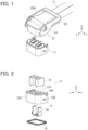
FIG. 1 is a perspective view showing a connector assembly according toEmbodiment 1 before fitting operation, with a lever member being situated in a first rotational position. -
FIG. 2 is an exploded perspective view of a first connector used inEmbodiment 1. -
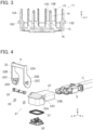
FIG. 3 is a cross-sectional view showing the first connector used inEmbodiment 1. -
FIG. 4 is an exploded perspective view of a second connector used inEmbodiment 1. -
FIG. 5 is a perspective view showing a rotational shaft member used inEmbodiment 1. -
FIG. 6 is an exploded perspective view of a second contact structure inEmbodiment 1. -
FIG. 7 is a perspective view showing a frame member used inEmbodiment 1. -
FIG. 8 is a side view showing the frame member used inEmbodiment 1. -
FIG. 9 is a plan view showing the frame member used in Embodiment 1. -
FIG. 10 is a cross-sectional perspective view showing the frame member used inEmbodiment 1. -
FIG. 11 is a bottom view showing the frame member joined with a second contact in Embodiment 1. -
FIG. 12 is a cross-sectional view showing the second connector used inEmbodiment 1. -
FIG. 13 is a partial perspective view showing the rotational shaft member when the lever member is situated in the first rotational position inEmbodiment 1. -
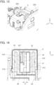
FIG. 14 is a cross-sectional front view showing an interior of the second connector before fitting operation, with the lever member being situated in the first rotational position inEmbodiment 1. -
FIG. 15 is a cross-sectional side view showing a state of the rotational shaft member and the second contact structure in the process of rotation of the lever member from the first rotational position to a second rotational position inEmbodiment 1. -
FIG. 16 is a partially broken perspective view showing a state of a cam surface of the rotational shaft member and the frame member of the second contact structure in the process of rotation of the lever member from the first rotational position to the second rotational position inEmbodiment 1. -
FIG. 17 is a perspective view showing the connector assembly according toEmbodiment 1 before fitting operation, with the lever member being situated in the second rotational position. -
FIG. 18 is a perspective view showing the second connector from which a second insulator has been removed with the lever member being situated in the second rotational position inEmbodiment 1. -
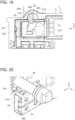
FIG. 19 is a cross-sectional side view showing a state of the rotational shaft member and the second contact structure before fitting operation, with the lever member being situated in the second rotational position inEmbodiment 1. -
FIG. 20 is a partial perspective view showing the rotational shaft member when the lever member is situated in the second rotational position inEmbodiment 1. -
FIG. 21 is a cross-sectional front view showing an interior of the second connector before fitting operation, with the lever member being situated in the second rotational position inEmbodiment 1. -
FIG. 22 is a cross-sectional front view showing the rotational shaft member before fitting operation, with the lever member being situated in the second rotational position inEmbodiment 1. -
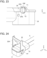
FIG. 23 is a side view showing an end of the rotational shaft member before fitting operation, with the lever member being situated in the second rotational position inEmbodiment 1. -
FIG. 24 is a perspective view showing the connector assembly according toEmbodiment 1 after fitting, with the lever member being situated in the second rotational position. -
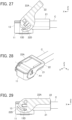
FIG. 25 is a cross-sectional front view showing an interior of the second connector after fitting, with the lever member being situated in the second rotational position inEmbodiment 1. -
FIG. 26 is a cross-sectional side view showing the connector assembly according toEmbodiment 1 after fitting, with the lever member being situated in the second rotational position. -
FIG. 27 is a cross-sectional side view showing the connector assembly according toEmbodiment 1 after fitting, with the lever member being in the process of rotation from the second rotational position to the first rotational position. -
FIG. 28 is a perspective view showing the connector assembly according toEmbodiment 1 after fitting, with the lever member being situated in the first rotational position. -
FIG. 29 is a cross-sectional side view showing the connector assembly according toEmbodiment 1 after fitting, with the lever member being situated in the first rotational position. -
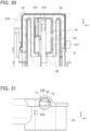
FIG. 30 is a cross-sectional front view showing an interior of the second connector after fitting, with the lever member being situated in the first rotational position inEmbodiment 1. -
FIG. 31 is a side view showing the end of the rotational shaft member before fitting operation, with the lever member being situated in the first rotational position inEmbodiment 1. -
FIG. 32 is a perspective view showing a connector assembly according toEmbodiment 2 before fitting operation, with the lever member being situated in the first rotational position. -
FIG. 33 is a perspective view showing a rotational shaft member used inEmbodiment 2. -
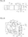
FIG. 34 is a front view showing a main portion of the rotational shaft member used in Embodiment 2. -
FIG. 35 is a perspective view showing a frame member used inEmbodiment 2. -
FIG. 36 is a partial perspective view showing the rotational shaft member when the lever member is situated in the first rotational position inEmbodiment 2. -
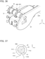
FIG. 37 is a cross-sectional view showing the rotational shaft member when the lever member is situated in the first rotational position inEmbodiment 2. -
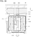
FIG. 38 is a cross-sectional front view showing an interior of a second connector before fitting operation, with the lever member being situated in the first rotational position inEmbodiment 2. -
FIG. 39 is a partial perspective view showing the rotational shaft member when the lever member is situated in the second rotational position inEmbodiment 2. -
FIG. 40 is a cross-sectional view showing the rotational shaft member when the lever member is situated in the first rotational position inEmbodiment 2. -
FIG. 41 is a cross-sectional front view showing an interior of the second connector before fitting operation, with the lever member being situated in the second rotational position inEmbodiment 2. -
FIG. 42 is a cross-sectional front view showing an interior of the second connector after fitting, with the lever member being situated in the second rotational position inEmbodiment 2. -
FIG. 43 is a cross-sectional front view showing an interior of the second connector after fitting, with the lever member being situated in the first rotational position inEmbodiment 2. -
FIG. 44 is a perspective view showing a conventional connector assembly before fitting operation. -
FIG. 45 is a cross-sectional view showing the conventional connector assembly in a fitted state. - Embodiments of the present invention are described below based on the accompanying drawings.
-
FIG. 1 shows a connector assembly according toEmbodiment 1 before fitting operation. The connector assembly includes afirst connector 11 and asecond connector 21 that is fitted to thefirst connector 11 along a fitting direction. For instance, when thefirst connector 11 is mounted on an electrical device (not shown) and thesecond connector 21 is attached to ends of two electric wires C, the connector assembly can detachably connect the two electric wires C to the electrical device. - Fitting and detachment between the
first connector 11 and thesecond connector 21 are carried out by rotating alever member 22 included in thesecond connector 21 about a rotational axis AX. - For convenience, the direction of fitting between the
first connector 11 and thesecond connector 21 is referred to as "Z direction," the direction in which the rotational axis AX of thelever member 22 extends as "Y direction," and the direction orthogonal to the Z direction and the Y direction as "X direction." - The
second connector 21 is moved from the +Z direction to the -Z direction to be fitted to thefirst connector 11. -
FIG. 2 shows an exploded perspective view of thefirst connector 11. Thefirst connector 11 includes afirst insulator 13, a pair offirst contacts 14 held by thefirst insulator 13, a pair ofmetal shells 15 corresponding to the pair offirst contacts 14, and awaterproof packing 16 for device mounting use. - The
first insulator 13 includes: a frame-likeouter wall portion 13A made of an insulating resin material, having a U-shape opening toward the -X direction when viewed from the Z direction, and extending in the Z direction; and a pair of projectingportions 13B arranged side by side in the Y direction inside theouter wall portion 13A. The pair of projectingportions 13B each have a U-shape opening toward the -X direction when viewed from the Z direction and extend in the Z direction. The interior of the projectingportion 13B forms a secondcontact accommodating portion 13C in a recess shape opening toward the +Z direction and extending in the Z direction. - A pair of
pins 13D are formed separately on the +Y directional outer surface and the -Y directional outer surface of theouter wall portion 13A to protrude in the Y direction. - The pair of
first contacts 14 are made of a metal material having conductivity, and as shown inFIG. 3 , held by thefirst insulator 13 by press-fitting or other methods. Eachfirst contact 14 projects within the corresponding secondcontact accommodating portion 13C of thefirst insulator 13 and extends in the +Z direction. Lateral surfaces of the pair of projectingportions 13B are covered with the correspondingmetal shells 15. - The pair of
pins 13D formed to protrude from theouter wall portion 13A of thefirst insulator 13 are arranged on the same straight line extending along the Y direction. - The
waterproof packing 16 for device mounting use is made of an elastic material such as rubber and disposed on the bottom surface of thefirst insulator 13 facing the -Z direction. -
FIG. 4 shows an exploded perspective view of thesecond connector 21. Thesecond connector 21 includes asecond insulator 23, a pair of second contact structures S connected to ends of two electric wires C, arotational shaft member 25 penetrating thesecond insulator 23 in the Y direction and rotatably attached to thesecond insulator 23, and thelever member 22 fixed to the opposite ends, in the Y direction, of therotational shaft member 25. - The
second insulator 23 includes afitting portion 23A of tubular shape made of an insulating resin material and extending in the Z direction and an electricwire connection portion 23B of tubular shape joined to the -X directional side of thefitting portion 23A and extending in the X direction. Thefitting portion 23A opens toward the - Z direction and is accommodated in thefirst connector 11 when thefirst connector 11 and thesecond connector 21 are fitted together. The electricwire connection portion 23B opens toward the -X direction and accommodates the pair of second contact structures S connected to the ends of the two electric wires C. - A pair of through
holes 23C through which therotational shaft member 25 extending in the Y direction penetrates are formed in the opposite lateral portions, in the Y direction, of thesecond insulator 23 at the +Z directional end of thefitting portion 23A. WhileFIG. 4 shows only the throughhole 23C formed in the +Y directional lateral portion of thesecond insulator 23, a like throughhole 23C is formed also in the -Y directional lateral portion of thesecond insulator 23. Those two throughholes 23C are arranged on the same straight line extending along the Y direction. - The
lever member 22 includes ahandle portion 22A bent in a U-shape and a pair offlat plate portions 22B joined separately to the opposite ends of thehandle portion 22A to face each other in the Y direction and each extending along an XZ plane. A grip portion H extending in the Y direction is formed at the distal end of thehandle portion 22A, and a pair offitting holes 22C are formed in the pair offlat plate portions 22B. The opposite ends of therotational shaft member 25 penetrating the pair of throughholes 23C of thesecond insulator 23 are jointed separately to the pair offitting holes 22C, whereby thelever member 22 is held in a rotatable manner with respect to thesecond insulator 23. -
Cam grooves 22D are separately formed at inner surfaces, facing each other, of the pair offlat plate portions 22B. WhileFIG. 4 shows only thecam groove 22D formed in theflat plate portion 22B on the -Y direction side, alike cam groove 22D is formed also in theflat plate portion 22B on the +Y direction side. - The pair of
pins 13D of thefirst insulator 13 are separately inserted into thecam grooves 22D of the pair offlat plate portions 22B, and thecam grooves 22D and thepins 13D constitute a fitting cam mechanism that relatively moves thefirst insulator 13 and thesecond insulator 23 along the Z direction in conjunction with rotation of thelever member 22. - The
second connector 21 further includes a pair of rotational shaftwaterproof packings 26 disposed at the opposite ends of therotational shaft member 25, a fitting portionwaterproof packing 27 disposed at the -Z directional end of thesecond insulator 23, and apacking holding member 28 preventing the fitting portion waterproof packing 27 from coming off thesecond insulator 23. - The rotational shaft
waterproof packings 26 each surround the corresponding end of therotational shaft member 25 along an XZ plane and seal between an inner surface of the corresponding throughhole 23C of thesecond insulator 23 and an outer peripheral surface of the corresponding end of therotational shaft member 25, and the fitting portion waterproof packing 27 seals between thefirst insulator 13 and thesecond insulator 23 when thefirst connector 11 and thesecond connector 21 are fitted together. - As shown in
FIG. 5 , therotational shaft member 25 includes ashaft body 25A extending in the Y direction along the rotational axis AX, and theshaft body 25A is provided at its opposite ends separately with a pair of roundcolumnar portions 25B that take the rotational axis AX as their center and have the same diameter. Protrudingplates 25C are disposed at a distance in the Y direction between the pair of roundcolumnar portions 25B to protrude in the radial direction from theshaft body 25A. Theshaft body 25A and the protrudingplates 25C have a common outer peripheral surface of cylindrical shape taking the rotational axis AX as their center. - The pair of round
columnar portions 25B are separately provided withpacking retaining grooves 25D of annular shape formed along an XZ plane in outer peripheral portions of the roundcolumnar portions 25B. The pair of rotational shaftwaterproof packings 26 shown inFIG. 4 are fitted in those packing retaininggrooves 25D and thereby retained in therotational shaft member 25. - Of the pair of round
columnar portions 25B, theround columnar portion 25B disposed on the +Y direction side is provided at its +Y directional end surface with aprotrusion 25E protruding in the +Y direction, and theround columnar portion 25B disposed on the -Y direction side is provided at its -Y directional end surface with aprotrusion 25F protruding in the -Y direction and having a different shape from that of theprotrusion 25E on the +Y direction side, in other words, extending longer in the Z direction than theprotrusion 25E. - Further, a
large diameter portion 25G having a larger diameter than theround columnar portion 25B is formed between thepacking retaining groove 25D and theprotrusion 25F to be adjacent to theround columnar portion 25B disposed on the -Y direction side. -
FIG. 6 shows an exploded perspective view of, of the pair of second contact structures S, the second contact structure S disposed on the +Y direction side. The second contact structure S includes: asecond contact 24 connected to the +X directional end of the electric wire C and made of a metal material having conductivity; and aframe member 31 attached to thesecond contact 24. - The second contact structure S further includes: a pair of
inner insulators second contact 24 to which theframe member 31 is attached, by sandwiching thesecond contact 24 from the +Y direction and the -Y direction; and a pair ofshells inner insulators inner insulators - As shown in
FIG. 7 , theframe member 31 is formed from a tubular metal plate having a substantially rectangular shape in YZ cross section and extending in the X direction, and includes atop surface portion 31A extending along an XY plane and situated on the +Z direction side, abottom surface portion 31B extending along an XY plane and situated on the -Z direction side, alateral surface portion 31C extending along an XZ plane and joining the +Y directional ends of thetop surface portion 31A and thebottom surface portion 31B together, and alateral surface portion 31D extending along an XZ plane and joining the -Y directional ends of thetop surface portion 31A and thebottom surface portion 31B together. - The
second contact 24 is disposed along the inner surface of thelateral surface portion 31C, and the correspondingfirst contact 14 of thefirst connector 11 is inserted to the interior of theframe member 31 through a firstcontact insertion port 31E formed in thebottom surface portion 31B in fitting between thefirst connector 11 and thesecond connector 21. - The
frame member 31 is provided in its interior with acontact spring member 31F formed from a plate spring made by cutting a metal plate constituting thelateral surface portion 31D into a substantially U-shape and bending the cut portion toward the interior of theframe member 31. Thecontact spring member 31F is configured to press thefirst contact 14, which has been inserted to the interior of theframe member 31 through the firstcontact insertion port 31E, against thesecond contact 24 disposed along the inner surface of thelateral surface portion 31C to bring thefirst contact 14 and thesecond contact 24 into contact with each other when thefirst connector 11 and thesecond connector 21 are fitted together. By elastic deformation of thecontact spring member 31F, a first contact insertion portion constituted of a space extending in the +Z direction from the firstcontact insertion port 31E is formed in the interior of theframe member 31. - The
frame member 31 further includes a frame movingspring member 31G formed from a plate spring made by cutting the metal plate constituting thelateral surface portion 31D into a U-shape and bending the cut portion toward the outside of theframe member 31, that is, bending the cut portion in the -Y direction from thelateral surface portion 31D. The frame movingspring member 31G is configured to move theframe member 31 in the Y direction by elastically contacting the inner surface of theinner insulator 33 in the second contact structure S in fitting between thefirst connector 11 and thesecond connector 21. The frame movingspring member 31G has an elastic force weaker than that of thecontact spring member 31F. - The
top surface portion 31A of theframe member 31 is provided with a protrudingplate insertion port 31H used to insert the protrudingplate 25C of therotational shaft member 25 to the interior of theframe member 31 in fitting between thefirst connector 11 and thesecond connector 21. The protrudingplate insertion port 31H is made by cutting a metal plate constituting thetop surface portion 31A into a U-shape and bending the cut portion toward the interior of theframe member 31, and the bent portion of the metal plate forms a protrudingplate receiving portion 31J extending along an XZ plane inside the protrudingplate insertion port 31H. - As shown in
FIG. 8 , thecontact spring member 31F is formed to be inclined with respect to the X direction and has a pair of cuts N1 and N2 formed at the opposite ends of thecontact spring member 31F in the width direction thereof in the metal plate constituting thelateral surface portion 31D. The cut N1 on the -Z direction side is longer than the cut N2 on the +Z direction side, and this configuration allows thecontact spring member 31F to have an elastic force gradually increasing toward the +Z direction. In other words, as shown inFIG. 7 , thecontact spring member 31F has an elastic force that gradually increases from the firstcontact insertion port 31E, which is an opening end of the first contact insertion portion formed inside theframe member 31, toward an inner part of the first contact insertion portion in the +Z direction. - Since the
contact spring member 31F is inclined with respect to the X direction, apressing portion 31K inclined with respect to the Z direction and linearly extending along an XZ plane is formed on thecontact spring member 31F as shown inFIGS. 9 and10 . - When the
second contact 24 is disposed along the inner surface of thelateral surface portion 31C of theframe member 31, thepressing portion 31K of thecontact spring member 31F faces thesecond contact 24 as shown inFIG. 11 . - The frame moving
spring member 31G formed in theframe member 31 projects in the -Y direction from thelateral surface portion 31D when receiving no external force. - It should be noted that, of the pair of second contact structures S, the second contact structure S disposed on the -Y direction side has a similar configuration as the second contact structure S disposed on the +Y direction side. The second contact structure S disposed on the -Y direction side is configured to be symmetrical in the Y direction to the second contact structure S disposed on the +Y direction side.
- As shown in
FIG. 12 , the pair of second contact structures S are fixed in a pair ofstructure accommodating portions 23D formed side by side in the Y direction in thesecond insulator 23. A framemember accommodating portion 36 is formed between theinner insulators frame member 31 is accommodated in the framemember accommodating portion 36. The dimension of the framemember accommodating portion 36 in the Y direction is larger than the length of theframe member 31 in the Y direction by a predetermined length, and theframe member 31 is accommodated to be movable in the Y direction within the framemember accommodating portion 36. - Next, the fitting operation between the
first connector 11 and thesecond connector 21 is described. - The rotational angle of the
lever member 22 with thehandle portion 22A extending in the X direction as shown inFIG. 1 is defined as "zero degrees," and the rotational position of thelever member 22 in this state is defined as "first rotational position." Thelever member 22 is rotatably attached to thesecond connector 21 such that the rotational angle can be changed from 0 degrees to 90 degrees. - When the
lever member 22 is in the first rotational position, as shown inFIG. 13 , the protrudingplate 25C formed in therotational shaft member 25 is situated on the +Z direction side of the second contact structure S and is not inserted in the interior of the second contact structure S. - At this time, no external force is exerted on the
contact spring member 31F of theframe member 31 as shown inFIG. 14 , and a gap G1 in the Y direction between thepressing portion 31K of thecontact spring member 31F and thesecond contact 24 has a dimension smaller than the thickness of thefirst contact 14 which is not shown herein. - From this state, as the rotational angle of the
lever member 22 is increased from 0 degrees toward 90 degrees, the protrudingplate 25C formed in therotational shaft member 25 starts to be inserted into theframe member 31 through the protrudingplate insertion port 31H formed in theframe member 31 of the second contact structure S as shown inFIG. 15 . - The protruding
plate 25C is provided with acam surface 25H inclined in the Y direction along the rotational axis AX of therotational shaft member 25, and thiscam surface 25H makes contact with an end, in the width direction, of thepressing portion 31K of thecontact spring member 31F of theframe member 31. Specifically, thecam surface 25H makes contact with the +Z directional end of thepressing portion 31K inclined with respect to the Z direction. - The
lever member 22 is further rotated up to the position where thehandle portion 22A makes an angle of 90 degrees with respect to the X direction as shown inFIG. 17 . The rotational position of thelever member 22 at this time is defined as "second rotational position." - When the
lever member 22 is in the second rotational position, as shown inFIG. 18 , the protrudingplate 25C of therotational shaft member 25 is inserted in the interior of the second contact structure S. It should be noted thatFIG. 18 shows the interior of thesecond connector 21 with thesecond insulator 23 being omitted. - Since the protruding
plate 25C is inserted to the interior of the second contact structure S with thecam surface 25H of the protrudingplate 25C being in contact with thepressing portion 31K of thecontact spring member 31F as shown inFIG. 16 , thepressing portion 31K of thecontact spring member 31F receives a force acting in the -Y direction from the protrudingplate 25C that has been inserted in the interior of theframe member 31 through the protrudingplate insertion port 31H of theframe member 31 as shown inFIGS. 19 and 20 . - Consequently, the
contact spring member 31F is elastically deformed, and thepressing portion 31K of thecontact spring member 31F is moved in the -Y direction away from thesecond contact 24 disposed along the inner surface of thelateral surface portion 31C of theframe member 31, as shown inFIG. 21 . As a result, a gap G2 in the Y direction having a dimension larger than the thickness of thefirst contact 14 is formed between thepressing portion 31K and thesecond contact 24. - Thus, a first contact insertion portion M that allows the
first contact 14 to be inserted along the Z direction without contacting thesecond contact 24 is formed between thepressing portion 31K of thecontact spring member 31F and thesecond contact 24. - It should be noted that the protruding
plate 25C elastically deforming thecontact spring member 31F receives a force acting in the +Y direction, as a reaction, from thecontact spring member 31F; however, since the protrudingplate 25C makes contact with and is supported by the protrudingplate receiving portion 31J of theframe member 31, the protrudingplate 25C can elastically deform thecontact spring member 31F without moving in the +Y direction. - The length from the rotational axis AX of the
rotational shaft member 25 to thehandle portion 22A of thelever member 22 is set larger than the length from the rotational axis AX to the protrudingplate 25C. Owing to this configuration, the protrudingplate 25C can be inserted into theframe member 31 to elastically deform thecontact spring member 31F by rotating thelever member 22 with a small operational force by use of thehandle portion 22A. - Furthermore, the
contact spring member 31F is configured to have an elastic force gradually increasing toward the +Z direction, and the protrudingplate 25C elastically deforms thecontact spring member 31F upon contacting the +Z directional end of thecontact spring member 31F, the +Z directional end having a larger elastic force. Accordingly, thecontact spring member 31F can be elastically deformed sufficiently even with a small amount of movement of the protrudingplate 25C in the Z direction, thus leading to a small size of thesecond connector 21. - As shown in
FIG. 19 , theinner insulator 32 of the second contact structure S is provided with arestriction surface 32A facing, from the +X direction, the common outer peripheral surface of cylindrical shape formed on theshaft body 25A and the protrudingplate 25C of therotational shaft member 25. - Therefore, even when a force acting in the -X direction is exerted on the second contact structure S via the
contact spring member 31F of theframe member 31 when the protrudingplate 25C elastically deforms thecontact spring member 31F, therestriction surface 32A makes contact with the outer peripheral surface of theshaft body 25A and the protrudingplate 25C of therotational shaft member 25 and thereby prevents the second contact structure S and the electric wire C from being pulled off thesecond insulator 23 in the -X direction. - As shown in
FIG. 22 , therotational shaft member 25 penetrates the pair of throughholes 23C of thesecond insulator 23 in the Y direction, and spaces between the inner surfaces of the pair of throughholes 23C of thesecond insulator 23 and the pair of roundcolumnar portions 25B of therotational shaft member 25 are separately sealed due to the presence of the rotational shaftwaterproof packings 26 retained in the pair ofpacking retaining grooves 25D of therotational shaft member 25. - The
large diameter portion 25G formed at the -Y directional end of therotational shaft member 25 and having a larger diameter than theround columnar portion 25B is rotatably accommodated in a shaftend accommodating portion 23E adjacent to the throughhole 23C of thesecond insulator 23 on the -Y direction side. No shaft endaccommodating portion 23E is formed in the vicinity of the throughhole 23C of thesecond insulator 23 on the +Y direction side. Accordingly, even when an attempt is made to insert therotational shaft member 25 to the pair of throughholes 23C of thesecond insulator 23 in a wrong orientation, thelarge diameter portion 25G of therotational shaft member 25 interferes with thesecond insulator 23 to prevent the pair of roundcolumnar portions 25B of therotational shaft member 25 from being accommodated in the pair of throughholes 23C of thesecond insulator 23. - Besides, as shown in
FIG. 23 , thelarge diameter portion 25G of therotational shaft member 25 projects in the -Y direction from thesecond insulator 23, and thelarge diameter portion 25G is provided with a first step portion T1 and a second step portion T2 in two places along the circumferential direction of therotational shaft member 25, each of the step portions T1 and T2 having a step in the radial direction. - The shaft
end accommodating portion 23E of thesecond insulator 23 is provided with astopper 23G protruding toward therotational shaft member 25. - The
stopper 23G selectively makes contact with the first step portion T1 and the second step portion T2 in accordance with the rotation of therotational shaft member 25. When thelever member 22 is situated in the second rotational position after being rotated up to the position where thehandle portion 22A makes an angle of 90 degrees with respect to the X direction as shown inFIG. 17 , thestopper 23G makes contact with the first step portion T1 to inhibit thelever member 22 from being rotated to the position where thehandle portion 22A is inclined to the +X direction side over 90 degrees. - With the
lever member 22 being in the second rotational position, thesecond connector 21 is moved toward thefirst connector 11 in the -Z direction, whereby thesecond connector 21 is fitted to thefirst connector 11 as shown inFIG. 24 . - The interior of the
second connector 21 at this time is shown inFIG. 25 . The frame movingspring member 31G of theframe member 31 makes contact with the inner surface of theinner insulator 33 within the framemember accommodating portion 36 formed between theinner insulators frame member 31 attached to thesecond contact 24 is pressed in the +Y direction against theinner insulators spring member 31G. - Thus, the
frame member 31 is moved in the +Y direction (first direction) within the framemember accommodating portion 36 until the outer surface of thelateral surface portion 31C on the +Y direction side makes contact with the inner surface, on the +Y direction side, of the framemember accommodating portion 36, so that a gap G3 is formed between the inner surface, on the -Y direction side, of the framemember accommodating portion 36 and the outer surface of thelateral surface portion 31D on the -Y direction side of theframe member 31. - In addition, due to the
lever member 22 being in the second rotational position, thecontact spring member 31F is elastically deformed, so that the gap G2 in the Y direction having a dimension larger than the thickness of thefirst contact 14 is formed between thepressing portion 31K of thecontact spring member 31F and thesecond contact 24. At this time, thesecond contact 24 is in a state where it has been moved in the +Y direction along with theframe member 31. Accordingly, thefirst contact 14 of thefirst connector 11 is inserted into the first contact insertion portion M, while forming a gap G4 with thesecond contact 24, without contacting thesecond contact 24. - When the
lever member 22 is in the second rotational position, as shown inFIG. 26 , thepin 13D of thefirst insulator 13 of thefirst connector 11 is not yet inserted to thecam groove 22D of thelever member 22 attached to thesecond connector 21. - From this state, when the
lever member 22 is rotated such that thehandle portion 22A is inclined toward the -X direction as shown inFIG. 27 , thepin 13D of thefirst insulator 13 of thefirst connector 11 starts to be inserted into thecam groove 22D of thelever member 22. - When the
lever member 22 is further rotated up to the first rotational position where thehandle portion 22A extends in the X direction as shown inFIG. 28 , thepin 13D of thefirst insulator 13 of thefirst connector 11 is inserted up to the deepest part of thecam groove 22D of thelever member 22 as shown inFIG. 29 , and the fitting state between thefirst connector 11 and thesecond connector 21 is locked. - Due to the
lever member 22 being in the first rotational position, the protrudingplate 25C of therotational shaft member 25 is retracted to the +Z direction side of theframe member 31 away from thecontact spring member 31F, and as shown inFIG. 30 , thepressing portion 31K of thecontact spring member 31F exerts a pressing force acting in the +Y direction to thefirst contact 14. - Consequently, the
frame member 31 receives a force acting in the -Y direction as a reaction; however, since the frame movingspring member 31G in contact with the inner surface of theinner insulator 33 has an elastic force weaker than an elastic force of thecontact spring member 31F, the frame movingspring member 31G elastically deforms, so that theframe member 31 is moved in the -Y direction (second direction) within the framemember accommodating portion 36 until the outer surface of thelateral surface portion 31D on the -Y direction side makes contact with the inner surface, on the -Y direction side, of the framemember accommodating portion 36. - As a result, the
second contact 24 is also moved in the -Y direction along with theframe member 31, so that thefirst contact 14 and thesecond contact 24 make contact with and are electrically connected to each other at a predetermined contact pressure. - Since the
first contact 14 and thesecond contact 24 are thus pressed against each other in the Y direction without rubbing against each other in the Z direction, it is possible to bring thefirst contact 14 and thesecond contact 24 into contact at a high contact pressure while easily fitting thefirst connector 11 and thesecond connector 21 together, thereby obtaining a reliable electrical connection. - When the
lever member 22 is rotated up to the first rotational position where thehandle portion 22A extends in the X direction, thestopper 23G formed at the shaftend accommodating portion 23E of thesecond insulator 23 makes contact with the second step portion T2 of therotational shaft member 25 as shown inFIG. 31 . In other words, the first step portion T1 and the second step portion T2 of therotational shaft member 25 and thestopper 23G constitute a rotation stopper mechanism that inhibits thelever member 22 from being rotated beyond the range between the first rotational position and the second rotational position. - To release the fitting between the
first connector 11 and thesecond connector 21 from the state where thefirst connector 11 and thesecond connector 21 are fitted together and thefirst contact 14 and thesecond contact 24 are electrically connected together, it is sufficient that thelever member 22 is rotated from the first rotational position to the second rotational position to unlock the fitting between thefirst connector 11 and thesecond connector 21, whereafter thesecond connector 21 is relatively pulled up in the +Z direction with respect to thefirst connector 11 and thereby detached from thefirst connector 11. - While, in
Embodiment 1 described above, thecam surface 25H used to elastically deform thecontact spring member 31F of theframe member 31 in thesecond connector 21 is formed on the protrudingplate 25C of therotational shaft member 25, the invention is not limited thereto. -
FIG. 32 shows a connector assembly according toEmbodiment 2 before fitting operation. This connector assembly is configured such that in the connector assembly according toEmbodiment 1, asecond connector 41 in place of thesecond connector 21 is fitted with thefirst connector 11, and thesecond connector 41 has thelever member 22 that is rotatable about the rotational axis AX as withEmbodiment 1. - The
second connector 41 is configured such that, in thesecond connector 21 used inEmbodiment 1, arotational shaft member 45 shown inFIG. 33 is used in place of therotational shaft member 25, and aframe member 51 shown inFIG. 35 is used in place of theframe member 31; thesecond connector 41 otherwise has the same configuration as thesecond connector 21 inEmbodiment 1. - The
rotational shaft member 45 used in thesecond connector 41 includes ashaft body 45A of round columnar shape extending in the Y direction along the rotational axis AX as shown inFIG. 33 . A pair ofpacking retaining grooves 25D are formed at the opposite ends, in the Y direction, of theshaft body 45A, andprotrusions shaft body 45A. Further, alarge diameter portion 25G is formed between thepacking retaining groove 25D at the -Y directional end of theshaft body 45A and theprotrusion 25F. Thepacking retaining grooves 25D, theprotrusion 25E, theprotrusion 25F, and thelarge diameter portion 25G are identical to those formed in therotational shaft member 25 inEmbodiment 1. - The
rotational shaft member 45 is provided with a pair of contactspring insertion grooves 45B of annular shape between the pair ofpacking retaining grooves 25D of theshaft body 45A, the pair of contactspring insertion grooves 45B being situated at a distance in the Y direction and extending in the circumferential direction of theshaft body 45A along an XZ plane. In addition, an abutmentportion insertion groove 45C of annular shape is formed on the +Y direction side of, of the pair of contactspring insertion grooves 45B, the contactspring insertion groove 45B situated on the +Y direction side to be adjacent thereto. Likewise, an abutmentportion insertion groove 45C of annular shape is formed also on the -Y direction side of the contactspring insertion groove 45B situated on the -Y direction side. These abutmentportion insertion grooves 45C extend in the circumferential direction of theshaft body 45A along an XZ plane. - As shown in
FIG. 34 , of the pair of contactspring insertion grooves 45B, the contactspring insertion groove 45B situated on the +Y direction side is provided in its interior with astep portion S 1 formed on the inner lateral surface of the contactspring insertion groove 45B, and a first lateral surface portion F11 and a second lateral surface portion F 12 are arranged adjacently in the circumferential direction of therotational shaft member 45 with the step portion S1 being disposed therebetween. The first lateralsurface portion F 11 and the second lateral surface portion F 12 each face the -Y direction along the rotational axis AX, and, due to the presence of thestep portion S 1, the second lateral surface portion F12 protrudes more in the -Y direction than the first lateralsurface portion F 11 by a distance L1 to form a cam surface of therotational shaft member 45. - Further, of the pair of abutment
portion insertion grooves 45C, the abutmentportion insertion groove 45C situated on the +Y direction side is provided in its interior with a step portion S2 formed on the inner lateral surface of the abutmentportion insertion groove 45C, and a first lateral surface portion F21 and a second lateral surface portion F22 are arranged adjacently in the circumferential direction of therotational shaft member 45 with the step portion S2 being disposed therebetween. The first lateral surface portion F21 and the second lateral surface portion F22 each face the +Y direction along the rotational axis AX, and, due to the presence of the step portion S2, the second lateral surface portion F22 protrudes more in the +Y direction than the first lateral surface portion F21 by a distance L2 to form an abutment portion receiving surface of therotational shaft member 45. - The first lateral surface portion F21 of the abutment
portion insertion groove 45C is disposed back to back with the first lateral surface portion F11 of the contactspring insertion groove 45B adjacent to the abutmentportion insertion groove 45C, and the second lateral surface portion F22 forming the abutment portion receiving surface of the abutmentportion insertion groove 45C is disposed back to back with the second lateral surface portion F12 forming the cam surface of the contactspring insertion groove 45B adjacent to the abutmentportion insertion groove 45C. - The contact
spring insertion groove 45B and the abutmentportion insertion groove 45C situated on the -Y direction side of therotational shaft member 45 are arranged and configured to be symmetrical in the Y direction to the contactspring insertion groove 45B and the abutmentportion insertion groove 45C situated on the +Y direction side of therotational shaft member 45. -
FIG. 35 shows theframe member 51 disposed in, of a pair of second contact structures S of thesecond connector 41, a second contact structure S situated on the +Y direction side. Theframe member 51 includes atop surface portion 31A extending along an XY plane and situated on the +Z direction side, abottom surface portion 31B extending along an XY plane and situated on the -Z direction side, alateral surface portion 31C extending along an XZ plane and joining the +Y directional ends of thetop surface portion 31A and thebottom surface portion 31B together, and alateral surface portion 31D extending along an XZ plane and joining the -Y directional ends of thetop surface portion 31A and thebottom surface portion 31B together, as with theframe member 31 inEmbodiment 1. - The
bottom surface portion 31B is provided with a firstcontact insertion port 31E used to insert thefirst contact 14 of thefirst connector 11, and thelateral surface portion 31D is provided with a frame movingspring member 31G made by cutting a metal plate constituting thelateral surface portion 31D into a U-shape and bending the cut portion in the -Y direction. - The
frame member 51 is further provided in its interior with acontact spring member 51A made by cutting the metal plate constituting thelateral surface portion 31D into a substantially U-shape and bending the cut portion toward the interior of theframe member 51, and thecontact spring member 51A is provided with apressing portion 51B inclined with respect to the Z direction and linearly extending along an XZ plane, as with theframe member 31 inEmbodiment 1. In theframe member 51, however, a +Zdirectional end portion 51C of thepressing portion 51B penetrates anopening 51D formed in thetop surface portion 31A and projects in the +Z direction from theframe member 51. - The frame moving
spring member 31G has an elastic force weaker than that of thecontact spring member 51A. - The
opening 51D is made by cutting a metal plate constituting thetop surface portion 31A into a U-shape and bending the cut portion in the +Z direction from thetop surface portion 31A, and the bent portion of the metal plate forms anabutment portion 51E that faces thepressing portion 51B of thecontact spring member 51A in the Y direction, theabutment portion 51E projecting in the +Z direction from thetop surface portion 31A. - Of the pair of second contact structures S, a second contact structure S disposed on the -Y direction side has a frame member configured to be symmetrical in the Y direction to the
frame member 51 shown inFIG. 35 . - In the
second connector 41, theend portion 51C of thepressing portion 51B of thecontact spring member 51A that projects in the +Z direction from thetop surface portion 31A of theframe member 51 is inserted into the contactspring insertion groove 45B of therotational shaft member 45, and theabutment portion 51E projecting in the +Z direction from thetop surface portion 31A of theframe member 51 is similarly inserted into the abutmentportion insertion groove 45C of therotational shaft member 45. - When the
lever member 22 is in the first rotational position as shown inFIG. 36 , the first lateral surface portion F11 of the contactspring insertion groove 45B of therotational shaft member 45 faces theend portion 51C of thepressing portion 51B of thecontact spring member 51A as shown inFIG. 37 . - Accordingly, as shown in
FIG. 38 , theend portion 51C of thepressing portion 51B of thecontact spring member 51A is situated apart from the first lateral surface portion F11 of the contactspring insertion groove 45B in the -Y direction and is not in contact with therotational shaft member 45. Thus, no external force is exerted on thecontact spring member 51A, and a gap G11 in the Y direction between thepressing portion 51B of thecontact spring member 51A and thesecond contact 24 has a dimension smaller than the thickness of thefirst contact 14 which is not shown herein. - It should be noted that, since the first lateral surface portion F21 of the abutment
portion insertion groove 45C is disposed back to back with the first lateral surface portion F11 of the contactspring insertion groove 45B, theabutment portion 51E of theframe member 51 is situated apart from the first lateral surface portion F21 of the abutmentportion insertion groove 45C in the +Y direction and is not in contact with therotational shaft member 45. - From this state, when the
lever member 22 is rotated to the second rotational position such that thehandle portion 22A makes an angle of 90 degrees with respect to the X direction as shown inFIG. 39 , therotational shaft member 45 also rotates about the rotational axis AX along with the rotation of thelever member 22, and as shown inFIG. 40 , the second lateral surface portion F12 of the contactspring insertion groove 45B of therotational shaft member 45 faces theend portion 51C of thepressing portion 51B of thecontact spring member 51A. - Since the second lateral surface portion F12 protrudes more in the -Y direction than the first lateral surface portion F11 by the distance L1, the second lateral surface portion F12 makes contact with the
end portion 51C of thepressing portion 51B of thecontact spring member 51A and presses theend portion 51C in the -Y direction. - Consequently, the
contact spring member 51A is elastically deformed, and thepressing portion 51B of thecontact spring member 51A is moved in the -Y direction away from thesecond contact 24 disposed along the inner surface of thelateral surface portion 31C of theframe member 51, as shown inFIG. 41 . As a result, a gap G12 in the Y direction having a dimension larger than the thickness of thefirst contact 14 is formed between thepressing portion 51B and thesecond contact 24. - Thus, a first contact insertion portion M that allows the
first contact 14 to be inserted along the Z direction without contacting thesecond contact 24 is formed between thepressing portion 51B of thecontact spring member 51A and thesecond contact 24. - At this time, the
end portion 51C of thepressing portion 51B of thecontact spring member 51A is pressed in the -Y direction by the second lateral surface portion F12 of the contactspring insertion groove 45B of therotational shaft member 45, and accordingly, a force acting in the -Y direction is exerted on theframe member 51. - However, the second lateral surface portion F22 of the abutment
portion insertion groove 45C that is situated back to back with the second lateral surface portion F12 of the contactspring insertion groove 45B protrudes more in the +Y direction than the first lateral surface portion F21 in therotational shaft member 45 and is therefore in contact with theabutment portion 51E of theframe member 51. - Thus, it is possible to elastically deform the
contact spring member 51A without theframe member 51 moving in the -Y direction within the framemember accommodating portion 36 formed between theinner insulators - In this state, the
second connector 41 is moved toward thefirst connector 11 in the -Z direction, whereby thesecond connector 21 is fitted to thefirst connector 11. As shown inFIG. 42 , the frame movingspring member 31G of theframe member 51 makes contact with the inner surface of theinner insulator 33 within the framemember accommodating portion 36 formed between theinner insulators frame member 51 attached to thesecond contact 24 is pressed in the +Y direction against theinner insulators spring member 31G. - Thus, the
frame member 51 is moved in the +Y direction (first direction) within the framemember accommodating portion 36 until the outer surface of thelateral surface portion 31C on the +Y direction side makes contact with the inner surface, on the +Y direction side, of the framemember accommodating portion 36, so that a gap G13 is formed between the inner surface, on the -Y direction side, of the framemember accommodating portion 36 and the outer surface of thelateral surface portion 31D on the -Y direction side of theframe member 51. - In addition, the
contact spring member 51A is elastically deformed, so that the gap G12 in the Y direction having a dimension larger than the thickness of thefirst contact 14 is formed between thepressing portion 51B of thecontact spring member 51A and thesecond contact 24, and thesecond contact 24 is in a state where it has been moved in the +Y direction along with theframe member 51. Accordingly, thefirst contact 14 of thefirst connector 11 is inserted into the first contact insertion portion M, while forming a gap G14 with thesecond contact 24, without contacting thesecond contact 24. - In this state, when the
lever member 22 is further rotated to the first rotational position, therotational shaft member 45 also rotates about the rotational axis AX along with the rotation of thelever member 22, and theend portion 51C of thepressing portion 51B of thecontact spring member 51A is moved away from the second lateral surface portion F12 of the contactspring insertion groove 45B of therotational shaft member 45 to face the first lateral surface portion F11 as shown inFIG. 37 . Consequently, theend portion 51C of thepressing portion 51B of thecontact spring member 51A makes no contact with therotational shaft member 45 as shown inFIG. 43 , and a pressing force acting in the +Y direction is exerted on thefirst contact 14 by thepressing portion 51B of thecontact spring member 51A. - As a result, the
frame member 51 receives a force acting in the -Y direction as a reaction. - In this process, the
abutment portion 51E of theframe member 51 is also moved away from the second lateral surface portion F22 of the abutmentportion insertion groove 45C to face the first lateral surface portion F21 and situated away from the first lateral surface portion F21 in the +Y direction. - Since the frame moving
spring member 31G in contact with the inner surface of theinner insulator 33 has an elastic force weaker than an elastic force of thecontact spring member 51A, the frame movingspring member 31G elastically deforms, so that theframe member 51 is moved in the -Y direction (second direction) within the framemember accommodating portion 36 until the outer surface, on the -Y direction side, of thelateral surface portion 31D makes contact with the inner surface, on the -Y direction side, of the framemember accommodating portion 36. - As a result, the
second contact 24 is also moved in the -Y direction along with theframe member 51, so that thefirst contact 14 and thesecond contact 24 make contact with and are electrically connected to each other at a predetermined contact pressure. - Also in
Embodiment 2, since thefirst contact 14 and thesecond contact 24 are thus pressed against each other in the Y direction without rubbing against each other in the Z direction, it is possible to bring thefirst contact 14 and thesecond contact 24 into contact at a high contact pressure while easily fitting thefirst connector 11 and thesecond connector 41 together, thereby obtaining a reliable electrical connection. - To release the fitting between the
first connector 11 and thesecond connector 41 from the state where thefirst connector 11 and thesecond connector 41 are fitted together and thefirst contact 14 and thesecond contact 24 are electrically connected together, it is sufficient that thelever member 22 is rotated from the first rotational position to the second rotational position to unlock the fitting between thefirst connector 11 and thesecond connector 41, whereafter thesecond connector 41 is relatively pulled up in the +Z direction with respect to thefirst connector 11 and thereby detached from theconnector 11, as withEmbodiment 1. - While, in
Embodiments 1 to 2 above, the first rotational position and the second rotational position of thelever member 22 are defined to correspond to rotational angles of thelever member 22 of 0 degrees and 90 degrees, respectively, the invention is not limited thereto, and the rotational positions may be defined to correspond to other rotational angles.
Claims (18)
- A connector assembly comprising:a first connector (11) including a first insulator (13) and a first contact (14) held by the first insulator;a second connector (21, 41) including a second insulator (23) and a second contact (24) held by the second insulator, the second connector being fitted to the first connector along a fitting direction;a contact spring member (3 1F, 51A) attached to the second contact and including a pressing portion (31K, 51B) configured to press the first contact against the second contact to bring the first contact and the second contact into contact with each other;a lever member (22) held by the second insulator and being rotatable about a rotational axis (AX) between a first rotational position and a second rotational position;a rotational shaft member (25, 45) held by the second insulator to rotate about the rotational axis along with rotation of the lever member and including a cam surface (25H, F12) configured to elastically deform the contact spring member; anda fitting cam mechanism (13D, 22D) relatively moving the first insulator and the second insulator along the fitting direction in conjunction with rotation of the lever member,wherein when the lever member is placed in the second rotational position, the cam surface of the rotational shaft member makes contact with and elastically deforms the contact spring member, whereby a first contact insertion portion (M) that allows the first contact to be inserted thereinto along the fitting direction is formed between the pressing portion and the second contact, andin a state where the first connector and the second connector are fitted together and the first contact is inserted in the first contact insertion portion, when the lever member is rotated from the second rotational position to the first rotational position, fitting between the first connector and the second connector is locked by the fitting cam mechanism, and the cam surface of the rotational shaft member is moved away from the contact spring member, so that the first contact and the second contact are pressed against each other by the pressing portion to make contact with each other.
- The connector assembly according to claim 1, comprising:a frame member (31, 51) attached to the second contact; andan inner insulator (32, 33) fixed inside the second insulator and provided with a frame member accommodating portion that accommodates the frame member such that the frame member is movable in a direction along the rotational axis,wherein the frame member is provided with the contact spring member and a frame moving spring member (31G) that elastically makes contact with the inner insulator, andwhen the cam surface makes contact with and elastically deforms the contact spring member, the frame member is moved in a first direction along the rotational axis with respect to the inner insulator due to an elastic force of the frame moving spring member, and a gap (G4, G14) is formed between the first contact inserted in the first contact insertion portion and the second contact.
- The connector assembly according to claim 2,wherein the frame moving spring member (31G) has an elastic force weaker than that of the contact spring member, andwhen the first contact is inserted in the first contact insertion portion and the cam surface is moved away from the contact spring member, the frame moving spring member elastically deforms upon receipt of an elastic force of the contact spring member, whereby the frame member (31, 51) is moved in a second direction opposite from the first direction with respect to the inner insulator, so that the first contact and the second contact make contact with each other.
- The connector assembly according to claim 3,
wherein the contact spring member (31F, 51A) and the frame moving spring member (31G) are each formed from a plate spring made by bending a part of the frame member. - The connector assembly according to claim 2,wherein the rotational shaft member (25) includes a protruding plate (25C) extending in a radial direction with respect to the rotational axis, andthe cam surface (25H) is formed on the protruding plate.
- The connector assembly according to claim 5,wherein the frame member (31) includes a protruding plate receiving portion (31J) that faces the pressing portion (31K) of the contact spring member (31F), andthe cam surface (25H) makes contact with an end portion of the pressing portion (31K) of the contact spring member to elastically deform the contact spring member in a state where the protruding plate (25C) is inserted between the pressing portion (31K) of the contact spring member and the protruding plate receiving portion (31J).
- The connector assembly according to claim 2,wherein the rotational shaft member (45) includes a contact spring insertion groove (45B) which extends in a circumferential direction along a plane perpendicular to the rotational axis and into which an end portion of the pressing portion (51B) of the contact spring member (51A) is inserted, andthe cam surface (F12) is formed from a lateral surface of the contact spring insertion groove.
- The connector assembly according to claim 7,wherein the frame member (51) includes an abutment portion (51E) that faces the pressing portion of the contact spring member,the rotational shaft member (45) includes an abutment portion receiving surface (F22) that extends along a plane perpendicular to the rotational axis and that faces in a direction along the rotational axis, andthe cam surface (F12) makes contact with the end portion of the pressing portion (51B) of the contact spring member (51A) to elastically deform the contact spring member in a state where the abutment portion (51B) is in contact with the abutment portion receiving surface upon rotation of the rotational shaft member.
- The connector assembly according to claim 8,wherein the rotational shaft member (45) includes an abutment portion insertion groove (45C) into which the abutment portion is inserted, andthe abutment portion receiving surface (F22) is formed from a lateral surface of the abutment portion insertion groove.
- The connector assembly according to any one of claims 1-9,wherein the cam surface (25H, F12) is inclined in a direction along the rotational axis (AX),the pressing portion (31K, 51B) of the contact spring member (31F, 51A) extends in a direction inclined with respect to the fitting direction, andthe cam surface makes contact with a widthwise end portion of the pressing portion to elastically deform the contact spring member along with rotation of the rotational shaft member.
- The connector assembly according to claim 10,wherein the contact spring member (31F, 51A) has an elastic force that gradually increases from an opening end of the first contact insertion portion (M) into which the first contact is inserted, toward an inner part of the first contact insertion portion along the fitting direction, andthe cam surface (25H, F12) makes contact with the end portion of the pressing portion (31K, 51B), the end portion being situated on the inner part side of the first contact insertion portion.
- The connector assembly according to claim 5,wherein an electric wire (C) is connected to the second contact (24) from a connection direction perpendicular to the fitting direction and the rotational axis,the protruding plate (25C) has an outer peripheral surface of cylindrical shape taking the rotational axis as its center, andthe inner insulator (32) includes a restriction surface (32A) that faces the outer peripheral surface of the protruding plate from a direction opposite from the electric wire along the connection direction.
- The connector assembly according to any one of claims 1-12,wherein the rotational shaft member (25, 45) includes a pair of round columnar portions (25B) disposed at opposite ends of the rotational shaft member along the rotational axis and having a same diameter, andthe second insulator (23) includes a pair of through-holes (23C) holding the pair of round columnar portions in a rotatable manner.
- The connector assembly according to claim 13,wherein the rotational shaft member (25, 45) includes a large diameter portion (25G) disposed adjacent to one of the pair of round columnar portions and having a diameter larger than that of one of the pair of round columnar portions, andthe second insulator (23) includes a shaft end accommodating portion (23E) disposed at only one end portion of the second insulator along the rotational axis and accommodating the large diameter portion.
- The connector assembly according to any one of claims 1-14, comprising a rotation stopper mechanism that inhibits the lever member (22) from being rotated beyond a range between the first rotational position and the second rotational position.
- The connector assembly according to claim 15,
wherein the rotation stopper mechanism includes: a first step portion (T1) and a second step portion (T2) that are formed in the rotational shaft member to correspond to the first rotational position and the second rotational position, respectively, and that each have a step in a radial direction; and a stopper (23G) that is formed in the second insulator (23) and that selectively makes contact with the first step portion and the second step portion in accordance with rotation of the rotational shaft member. - The connector assembly according to any one of claims 1-16,wherein the lever member (22) includes a handle portion (22A), anda length from the rotational axis to the handle portion is larger than a length from the rotational axis to the cam surface of the rotational shaft member.
- The connector assembly according to claim 17,
wherein the fitting cam mechanism includes a cam groove (22D) formed in the lever member (22) and a pin (13D) that is formed to protrude on the first insulator (13) and that is inserted into the cam groove.
Applications Claiming Priority (1)
| Application Number | Priority Date | Filing Date | Title |
|---|---|---|---|
| JP2023010348A JP2024106182A (en) | 2023-01-26 | 2023-01-26 | Connector Assembly |
Publications (2)
| Publication Number | Publication Date |
|---|---|
| EP4407807A1 true EP4407807A1 (en) | 2024-07-31 |
| EP4407807B1 EP4407807B1 (en) | 2025-01-29 |
Family
ID=88792992
Family Applications (1)
| Application Number | Title | Priority Date | Filing Date |
|---|---|---|---|
| EP23209792.3A Active EP4407807B1 (en) | 2023-01-26 | 2023-11-14 | Connector assembly |
Country Status (4)
| Country | Link |
|---|---|
| US (1) | US20240258743A1 (en) |
| EP (1) | EP4407807B1 (en) |
| JP (1) | JP2024106182A (en) |
| CN (1) | CN118399132A (en) |
Citations (4)
| Publication number | Priority date | Publication date | Assignee | Title |
|---|---|---|---|---|
| CN103633501A (en) * | 2012-08-24 | 2014-03-12 | 泰科电子日本合同会社 | Low insertion force type connector |
| JP2018152265A (en) | 2017-03-14 | 2018-09-27 | 矢崎総業株式会社 | Waterproof connector mating structure |
| US20190296485A1 (en) * | 2018-03-20 | 2019-09-26 | Yazaki Corporation | Connector |
| US20210159641A1 (en) * | 2017-09-28 | 2021-05-27 | Autonetworks Technologies, Ltd. | Lever-type connector |
Family Cites Families (3)
| Publication number | Priority date | Publication date | Assignee | Title |
|---|---|---|---|---|
| JP3710705B2 (en) * | 2000-11-30 | 2005-10-26 | タイコエレクトロニクスアンプ株式会社 | Low insertion force connector |
| JP4446278B2 (en) * | 2006-10-05 | 2010-04-07 | Smk株式会社 | Double-sided printed wiring board connector |
| US9559467B1 (en) * | 2015-08-17 | 2017-01-31 | Foxconn Interconnect Technology Limited | Connector assembly with reliable electrical connection |
-
2023
- 2023-01-26 JP JP2023010348A patent/JP2024106182A/en active Pending
- 2023-11-02 US US18/500,488 patent/US20240258743A1/en active Pending
- 2023-11-09 CN CN202311490322.4A patent/CN118399132A/en active Pending
- 2023-11-14 EP EP23209792.3A patent/EP4407807B1/en active Active
Patent Citations (4)
| Publication number | Priority date | Publication date | Assignee | Title |
|---|---|---|---|---|
| CN103633501A (en) * | 2012-08-24 | 2014-03-12 | 泰科电子日本合同会社 | Low insertion force type connector |
| JP2018152265A (en) | 2017-03-14 | 2018-09-27 | 矢崎総業株式会社 | Waterproof connector mating structure |
| US20210159641A1 (en) * | 2017-09-28 | 2021-05-27 | Autonetworks Technologies, Ltd. | Lever-type connector |
| US20190296485A1 (en) * | 2018-03-20 | 2019-09-26 | Yazaki Corporation | Connector |
Also Published As
| Publication number | Publication date |
|---|---|
| CN118399132A (en) | 2024-07-26 |
| JP2024106182A (en) | 2024-08-07 |
| EP4407807B1 (en) | 2025-01-29 |
| US20240258743A1 (en) | 2024-08-01 |
Similar Documents
| Publication | Publication Date | Title |
|---|---|---|
| EP1111728B1 (en) | Connector with an improved guide portion for guiding connection of the connector and an object to be connected thereto | |
| KR101041318B1 (en) | L type coaxial connector | |
| US12444882B2 (en) | Connector assembly | |
| EP0913891A2 (en) | Electrical connector | |
| CN112713425B (en) | Connector and connecting method | |
| US10211570B2 (en) | Lever-fitting type connector | |
| EP4181324A1 (en) | Connector assembly and waterproof cap | |
| US6736659B1 (en) | Cable connector assembly | |
| CN115714278A (en) | Fitting structure of housing and connector | |
| JP2018014165A (en) | Lever fitting type connector | |
| EP4407807B1 (en) | Connector assembly | |
| US12489248B2 (en) | Connector assembly for fitting a first connector and a second connector upon rotation of a lever member | |
| CN115224539A (en) | Board Mount Connector | |
| EP4462605B1 (en) | Connector | |
| WO2025218035A1 (en) | Connector and connector assembly | |
| US6371789B1 (en) | Connection apparatus having an improved locking mechanism for maintaining a connection state | |
| JP2008159481A (en) | Terminal device | |
| EP4632961A1 (en) | Connector assembly | |
| JP3319858B2 (en) | Wiring connection device | |
| JP7601738B2 (en) | Connector part having attachment structure for separate member | |
| US20250167499A1 (en) | Connector assembly | |
| US12300922B2 (en) | Connector with a reinforcing member | |
| JP7409241B2 (en) | connector | |
| WO2018074537A1 (en) | Terminal device and wiring fixture equipped with same | |
| KR20240177057A (en) | Lever type connector |
Legal Events
| Date | Code | Title | Description |
|---|---|---|---|
| PUAI | Public reference made under article 153(3) epc to a published international application that has entered the european phase |
Free format text: ORIGINAL CODE: 0009012 |
|
| STAA | Information on the status of an ep patent application or granted ep patent |
Free format text: STATUS: REQUEST FOR EXAMINATION WAS MADE |
|
| 17P | Request for examination filed |
Effective date: 20231114 |
|
| AK | Designated contracting states |
Kind code of ref document: A1 Designated state(s): AL AT BE BG CH CY CZ DE DK EE ES FI FR GB GR HR HU IE IS IT LI LT LU LV MC ME MK MT NL NO PL PT RO RS SE SI SK SM TR |
|
| RBV | Designated contracting states (corrected) |
Designated state(s): AL AT BE BG CH CY CZ DE DK EE ES FI FR GB GR HR HU IE IS IT LI LT LU LV MC ME MK MT NL NO PL PT RO RS SE SI SK SM TR |
|
| GRAP | Despatch of communication of intention to grant a patent |
Free format text: ORIGINAL CODE: EPIDOSNIGR1 |
|
| STAA | Information on the status of an ep patent application or granted ep patent |
Free format text: STATUS: GRANT OF PATENT IS INTENDED |
|
| RIC1 | Information provided on ipc code assigned before grant |
Ipc: H01R 13/11 20060101ALN20241002BHEP Ipc: H01R 13/629 20060101ALI20241002BHEP Ipc: H01R 13/193 20060101ALI20241002BHEP Ipc: H01R 4/50 20060101AFI20241002BHEP |
|
| INTG | Intention to grant announced |
Effective date: 20241015 |
|
| GRAS | Grant fee paid |
Free format text: ORIGINAL CODE: EPIDOSNIGR3 |
|
| GRAA | (expected) grant |
Free format text: ORIGINAL CODE: 0009210 |
|
| STAA | Information on the status of an ep patent application or granted ep patent |
Free format text: STATUS: THE PATENT HAS BEEN GRANTED |
|
| AK | Designated contracting states |
Kind code of ref document: B1 Designated state(s): AL AT BE BG CH CY CZ DE DK EE ES FI FR GB GR HR HU IE IS IT LI LT LU LV MC ME MK MT NL NO PL PT RO RS SE SI SK SM TR |
|
| REG | Reference to a national code |
Ref country code: GB Ref legal event code: FG4D |
|
| REG | Reference to a national code |
Ref country code: CH Ref legal event code: EP |
|
| REG | Reference to a national code |
Ref country code: DE Ref legal event code: R096 Ref document number: 602023001913 Country of ref document: DE |
|
| REG | Reference to a national code |
Ref country code: IE Ref legal event code: FG4D |
|
| REG | Reference to a national code |
Ref country code: NL Ref legal event code: MP Effective date: 20250129 |
|
| PG25 | Lapsed in a contracting state [announced via postgrant information from national office to epo] |
Ref country code: NL Free format text: LAPSE BECAUSE OF FAILURE TO SUBMIT A TRANSLATION OF THE DESCRIPTION OR TO PAY THE FEE WITHIN THE PRESCRIBED TIME-LIMIT Effective date: 20250129 |
|
| PG25 | Lapsed in a contracting state [announced via postgrant information from national office to epo] |
Ref country code: RS Free format text: LAPSE BECAUSE OF FAILURE TO SUBMIT A TRANSLATION OF THE DESCRIPTION OR TO PAY THE FEE WITHIN THE PRESCRIBED TIME-LIMIT Effective date: 20250429 |
|
| PG25 | Lapsed in a contracting state [announced via postgrant information from national office to epo] |
Ref country code: FI Free format text: LAPSE BECAUSE OF FAILURE TO SUBMIT A TRANSLATION OF THE DESCRIPTION OR TO PAY THE FEE WITHIN THE PRESCRIBED TIME-LIMIT Effective date: 20250129 |
|
| PG25 | Lapsed in a contracting state [announced via postgrant information from national office to epo] |
Ref country code: PL Free format text: LAPSE BECAUSE OF FAILURE TO SUBMIT A TRANSLATION OF THE DESCRIPTION OR TO PAY THE FEE WITHIN THE PRESCRIBED TIME-LIMIT Effective date: 20250129 |
|
| PG25 | Lapsed in a contracting state [announced via postgrant information from national office to epo] |
Ref country code: ES Free format text: LAPSE BECAUSE OF FAILURE TO SUBMIT A TRANSLATION OF THE DESCRIPTION OR TO PAY THE FEE WITHIN THE PRESCRIBED TIME-LIMIT Effective date: 20250129 |
|
| REG | Reference to a national code |
Ref country code: LT Ref legal event code: MG9D |
|
| PG25 | Lapsed in a contracting state [announced via postgrant information from national office to epo] |
Ref country code: IS Free format text: LAPSE BECAUSE OF FAILURE TO SUBMIT A TRANSLATION OF THE DESCRIPTION OR TO PAY THE FEE WITHIN THE PRESCRIBED TIME-LIMIT Effective date: 20250529 Ref country code: NO Free format text: LAPSE BECAUSE OF FAILURE TO SUBMIT A TRANSLATION OF THE DESCRIPTION OR TO PAY THE FEE WITHIN THE PRESCRIBED TIME-LIMIT Effective date: 20250429 |
|
| REG | Reference to a national code |
Ref country code: AT Ref legal event code: MK05 Ref document number: 1764427 Country of ref document: AT Kind code of ref document: T Effective date: 20250129 |
|
| PG25 | Lapsed in a contracting state [announced via postgrant information from national office to epo] |
Ref country code: HR Free format text: LAPSE BECAUSE OF FAILURE TO SUBMIT A TRANSLATION OF THE DESCRIPTION OR TO PAY THE FEE WITHIN THE PRESCRIBED TIME-LIMIT Effective date: 20250129 |
|
| PG25 | Lapsed in a contracting state [announced via postgrant information from national office to epo] |
Ref country code: LV Free format text: LAPSE BECAUSE OF FAILURE TO SUBMIT A TRANSLATION OF THE DESCRIPTION OR TO PAY THE FEE WITHIN THE PRESCRIBED TIME-LIMIT Effective date: 20250129 Ref country code: PT Free format text: LAPSE BECAUSE OF FAILURE TO SUBMIT A TRANSLATION OF THE DESCRIPTION OR TO PAY THE FEE WITHIN THE PRESCRIBED TIME-LIMIT Effective date: 20250529 |
|
| PG25 | Lapsed in a contracting state [announced via postgrant information from national office to epo] |
Ref country code: BG Free format text: LAPSE BECAUSE OF FAILURE TO SUBMIT A TRANSLATION OF THE DESCRIPTION OR TO PAY THE FEE WITHIN THE PRESCRIBED TIME-LIMIT Effective date: 20250129 Ref country code: GR Free format text: LAPSE BECAUSE OF FAILURE TO SUBMIT A TRANSLATION OF THE DESCRIPTION OR TO PAY THE FEE WITHIN THE PRESCRIBED TIME-LIMIT Effective date: 20250430 |
|
| PG25 | Lapsed in a contracting state [announced via postgrant information from national office to epo] |
Ref country code: AT Free format text: LAPSE BECAUSE OF FAILURE TO SUBMIT A TRANSLATION OF THE DESCRIPTION OR TO PAY THE FEE WITHIN THE PRESCRIBED TIME-LIMIT Effective date: 20250129 |
|
| PG25 | Lapsed in a contracting state [announced via postgrant information from national office to epo] |
Ref country code: SE Free format text: LAPSE BECAUSE OF FAILURE TO SUBMIT A TRANSLATION OF THE DESCRIPTION OR TO PAY THE FEE WITHIN THE PRESCRIBED TIME-LIMIT Effective date: 20250129 |
|
| PG25 | Lapsed in a contracting state [announced via postgrant information from national office to epo] |
Ref country code: SM Free format text: LAPSE BECAUSE OF FAILURE TO SUBMIT A TRANSLATION OF THE DESCRIPTION OR TO PAY THE FEE WITHIN THE PRESCRIBED TIME-LIMIT Effective date: 20250129 |
|
| PG25 | Lapsed in a contracting state [announced via postgrant information from national office to epo] |
Ref country code: DK Free format text: LAPSE BECAUSE OF FAILURE TO SUBMIT A TRANSLATION OF THE DESCRIPTION OR TO PAY THE FEE WITHIN THE PRESCRIBED TIME-LIMIT Effective date: 20250129 |
|
| PGFP | Annual fee paid to national office [announced via postgrant information from national office to epo] |
Ref country code: FR Payment date: 20250930 Year of fee payment: 3 |
|
| PG25 | Lapsed in a contracting state [announced via postgrant information from national office to epo] |
Ref country code: EE Free format text: LAPSE BECAUSE OF FAILURE TO SUBMIT A TRANSLATION OF THE DESCRIPTION OR TO PAY THE FEE WITHIN THE PRESCRIBED TIME-LIMIT Effective date: 20250129 Ref country code: CZ Free format text: LAPSE BECAUSE OF FAILURE TO SUBMIT A TRANSLATION OF THE DESCRIPTION OR TO PAY THE FEE WITHIN THE PRESCRIBED TIME-LIMIT Effective date: 20250129 |
|
| PG25 | Lapsed in a contracting state [announced via postgrant information from national office to epo] |
Ref country code: RO Free format text: LAPSE BECAUSE OF FAILURE TO SUBMIT A TRANSLATION OF THE DESCRIPTION OR TO PAY THE FEE WITHIN THE PRESCRIBED TIME-LIMIT Effective date: 20250129 |
|
| PG25 | Lapsed in a contracting state [announced via postgrant information from national office to epo] |
Ref country code: SK Free format text: LAPSE BECAUSE OF FAILURE TO SUBMIT A TRANSLATION OF THE DESCRIPTION OR TO PAY THE FEE WITHIN THE PRESCRIBED TIME-LIMIT Effective date: 20250129 |
|
| REG | Reference to a national code |
Ref country code: DE Ref legal event code: R097 Ref document number: 602023001913 Country of ref document: DE |
|
| PLBE | No opposition filed within time limit |
Free format text: ORIGINAL CODE: 0009261 |
|
| STAA | Information on the status of an ep patent application or granted ep patent |
Free format text: STATUS: NO OPPOSITION FILED WITHIN TIME LIMIT |
|
| 26N | No opposition filed |
Effective date: 20251030 |
|
| PGFP | Annual fee paid to national office [announced via postgrant information from national office to epo] |
Ref country code: DE Payment date: 20250930 Year of fee payment: 3 |
|
| PGFP | Annual fee paid to national office [announced via postgrant information from national office to epo] |
Ref country code: IT Payment date: 20251201 Year of fee payment: 3 |
|
| PG25 | Lapsed in a contracting state [announced via postgrant information from national office to epo] |
Ref country code: LT Free format text: LAPSE BECAUSE OF FAILURE TO SUBMIT A TRANSLATION OF THE DESCRIPTION OR TO PAY THE FEE WITHIN THE PRESCRIBED TIME-LIMIT Effective date: 20250129 |
|
| PG25 | Lapsed in a contracting state [announced via postgrant information from national office to epo] |
Ref country code: MC Free format text: LAPSE BECAUSE OF FAILURE TO SUBMIT A TRANSLATION OF THE DESCRIPTION OR TO PAY THE FEE WITHIN THE PRESCRIBED TIME-LIMIT Effective date: 20250129 |
|
| PG25 | Lapsed in a contracting state [announced via postgrant information from national office to epo] |
Ref country code: LU Free format text: LAPSE BECAUSE OF NON-PAYMENT OF DUE FEES Effective date: 20251114 |