EP4407792A1 - Clamping apparatus for antenna device - Google Patents
Clamping apparatus for antenna device Download PDFInfo
- Publication number
- EP4407792A1 EP4407792A1 EP22873195.6A EP22873195A EP4407792A1 EP 4407792 A1 EP4407792 A1 EP 4407792A1 EP 22873195 A EP22873195 A EP 22873195A EP 4407792 A1 EP4407792 A1 EP 4407792A1
- Authority
- EP
- European Patent Office
- Prior art keywords
- clamping
- support pole
- gear plate
- band
- clamping block
- Prior art date
- Legal status (The legal status is an assumption and is not a legal conclusion. Google has not performed a legal analysis and makes no representation as to the accuracy of the status listed.)
- Pending
Links
Images





Classifications
-
- H—ELECTRICITY
- H01—ELECTRIC ELEMENTS
- H01Q—ANTENNAS, i.e. RADIO AERIALS
- H01Q1/00—Details of, or arrangements associated with, antennas
- H01Q1/12—Supports; Mounting means
- H01Q1/1242—Rigid masts specially adapted for supporting an aerial
-
- F—MECHANICAL ENGINEERING; LIGHTING; HEATING; WEAPONS; BLASTING
- F16—ENGINEERING ELEMENTS AND UNITS; GENERAL MEASURES FOR PRODUCING AND MAINTAINING EFFECTIVE FUNCTIONING OF MACHINES OR INSTALLATIONS; THERMAL INSULATION IN GENERAL
- F16B—DEVICES FOR FASTENING OR SECURING CONSTRUCTIONAL ELEMENTS OR MACHINE PARTS TOGETHER, e.g. NAILS, BOLTS, CIRCLIPS, CLAMPS, CLIPS OR WEDGES; JOINTS OR JOINTING
- F16B2/00—Friction-grip releasable fastenings
- F16B2/02—Clamps, i.e. with gripping action effected by positive means other than the inherent resistance to deformation of the material of the fastening
- F16B2/06—Clamps, i.e. with gripping action effected by positive means other than the inherent resistance to deformation of the material of the fastening external, i.e. with contracting action
- F16B2/08—Clamps, i.e. with gripping action effected by positive means other than the inherent resistance to deformation of the material of the fastening external, i.e. with contracting action using bands
-
- F—MECHANICAL ENGINEERING; LIGHTING; HEATING; WEAPONS; BLASTING
- F16—ENGINEERING ELEMENTS AND UNITS; GENERAL MEASURES FOR PRODUCING AND MAINTAINING EFFECTIVE FUNCTIONING OF MACHINES OR INSTALLATIONS; THERMAL INSULATION IN GENERAL
- F16M—FRAMES, CASINGS OR BEDS OF ENGINES, MACHINES OR APPARATUS, NOT SPECIFIC TO ENGINES, MACHINES OR APPARATUS PROVIDED FOR ELSEWHERE; STANDS; SUPPORTS
- F16M13/00—Other supports for positioning apparatus or articles; Means for steadying hand-held apparatus or articles
- F16M13/02—Other supports for positioning apparatus or articles; Means for steadying hand-held apparatus or articles for supporting on, or attaching to, an object, e.g. tree, gate, window-frame, cycle
- F16M13/022—Other supports for positioning apparatus or articles; Means for steadying hand-held apparatus or articles for supporting on, or attaching to, an object, e.g. tree, gate, window-frame, cycle repositionable
-
- H—ELECTRICITY
- H01—ELECTRIC ELEMENTS
- H01Q—ANTENNAS, i.e. RADIO AERIALS
- H01Q1/00—Details of, or arrangements associated with, antennas
- H01Q1/12—Supports; Mounting means
- H01Q1/1207—Supports; Mounting means for fastening a rigid aerial element
- H01Q1/1228—Supports; Mounting means for fastening a rigid aerial element on a boom
Definitions
- the present disclosure relates to a clamping apparatus for an antenna device, and more particularly, to a clamping apparatus for an antenna device, which is provided so that two or more antenna devices are easily installed on an outer circumferential surface of a support pole including horizontal cross sections having various shapes.
- a wireless communication technology for example, a multiple input multiple output (MIMO) technology
- MIMO multiple input multiple output
- a wireless communication technology is a technology for significantly increasing a data transmission capacity by using multiple antennas, and is a spatial multiplexing scheme in which a transmitter transmits different data through transmission antennas and a receiver distinguishes between transmission data through proper signal processing.
- a channel capacity may be increased as the numbers of transmission and reception antennas are simultaneously increased. For example, if the number of antennas is increased to 10, a channel capacity that is about 10 times compared to a current single antenna system is secured by using the same frequency band.
- Massive MIMO requires a high output for the extension of coverage. Consumption power and the amount of heat generated attributable to such a high output act as a negative factor in reducing a weight and a size.
- the present disclosure has been contrived to solve the technical problems, and an object of the present disclosure is to provide a clamping apparatus for an antenna device in which an antenna device can be universally installed in one support pole having various horizontal cross-sectional shapes.
- another object of the present disclosure is to provide a clamping apparatus for an antenna device, which can prevent a product from being damaged due to a downward slip phenomenon attributable to the weight of the antenna device by being closely attached to an outer surface of a support pole.
- a clamping apparatus for an antenna device includes two or more clamping block bodies each closely attached and combined to occupy a part of an outer surface of a support pole that has extended to be orthogonal to an installation surface thereof, and a clamping band configured to simultaneously penetrate the two or more clamping block bodies, wherein at least some of the clamping band closely attaches and combines the two or more clamping block bodies on the outer surface of the support pole by coming into contact with the outer surface of the support pole.
- a portion of the clamping band which corresponds to a portion between the two or more clamping block bodies, may be closely attached to the outer surface of the support pole in a tightening way.
- the horizontal cross-sectional shape of the support pole may include any one of a circle, a triangle, a quadrangle, and a hexagon.
- a clamping gear plate having gear teeth closely attached to the outer surface of the support pole may be detachably provided in each of the two or more clamping block bodies.
- the two or more clamping block bodies may each include an edge block closely attached to the outer surface of the support pole and having an inner end provided with at least one horizontal installation slit for attaching and detaching and installing the clamping gear plate and a connection block in which a medium installation part that is horizontally extended from both ends of the edge block to an outside and mediates an installation of an antenna device has been extended and formed.
- the horizontal installation slit may include two upper horizontal installation slit and lower horizontal installation slit that are spaced apart from each other up and down at an inner end of the edge block adjacent to the outer surface of the support pole.
- the clamping gear plate may include an upper gear plate and a lower gear plate that are installed in the upper horizontal installation slit and the lower horizontal installation slit that have been formed to be spaced apart from each other up and down, respectively.
- a gear top land that protrudes in a direction toward the outer surface of the support pole and a gear bottom land that is depressed in a direction in which the gear bottom land becomes distant from the outer surface of the support pole may be repeated and formed in the gear teeth of the clamping gear plate.
- a virtual line that connects front ends of the gear top lands of the gear teeth of the clamping gear plate may be formed in a shape corresponding to the outer surface of the support pole.
- a band installation hole that has been penetrated so that the band installation hole has the center of the support pole as a concentric circle for the penetration and combination of the clamping band may be formed in the edge block.
- the clamping band may include a band part configured to penetrate the band installation hole and to closely attach the clamping block body to the support pole upon tightening and fastening and a fixing part configured to fix the band part after generating a predetermined tightening force to the band part.
- clamping block body may occupy a cross section of a part of the outer surface that is formed by a horizontal cross-sectional shape of the support pole, wherein two or more clamping block bodies may be installed to be adjacent to each other or spaced apart from each other.
- the horizontal cross-sectional shape of the support pole may include any one of a circle, a triangle, a quadrangle, and a hexagon.
- the remaining external shapes except an end at which the gear teeth of the clamping gear plate have been formed may have an identical shape regardless of the horizontal cross-sectional shape of the support pole.
- a length between an outer end of the upper gear plate at which the gear teeth have been formed and an inner end of the upper gear plate, which is disposed within the horizontal installation slit, and a length between an outer end of the lower gear plate at which the gear teeth have been formed and an inner end of the lower gear plate, which is disposed within the horizontal installation slit, may be different so that the clamping block body is tilted and installed.
- the clamping apparatus for an antenna device there is an effect in that installation versatility is improved because the clamping apparatus can be firmly installed in the support pole by replacing the clamping gear plate that is matched with a horizontal cross-sectional shape of the support pole.
- 1A to 1D support pole 100A to 100D: clamping apparatus for antenna device 110, 120: clamping block body 110: edge block 111: band installation hole 113: fixing hole 115a, 115b: clamping gear plate 117: horizontal installation slit 119: fixing member 120: connection block 130: clamping band 131: band part 133: fixing part
- Clamping apparatuses 100A to 100D for an antenna device according to the present disclosure each play a role as a medium that enables multiple antenna devices (not illustrated) to be stably installed at the same height with each of support poles 1A to 1D.
- the clamping apparatuses 100A to 100D for an antenna device each include a clamping block body 110 and 120 that is installed in each of the support poles 1A to 1D having various horizontal cross sections and a clamping band 130 that fixes the clamping block body 110 and 120 to each of the support poles 1A to 1D.
- the clamping block body 110 and 120 may include a clamping gear plate 115a and 115b in which gear teeth that generate a friction force to an outer circumferential surface (or an outer surface) of each of the support poles 1A to 1D by a tightening force of the clamping band 130 are provided at an inner circumferential end thereof.
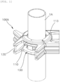
- FIG. 1 is a perspective view illustrating a clamping apparatus for an antenna device according to a first embodiment of the present disclosure.
- FIG. 2 is an exploded perspective view of FIG. 1 .
- FIG. 3 is a perspective view illustrating a form in which a clamping band is installed in a unit clamping block body, among the components of FIG. 1 .
- FIG. 4 is a perspective view illustrating an installation shape of the unit clamping block body for a support pole using a clamping band, among the components of FIG. 1 .
- FIG. 5 is a cutaway perspective view illustrating a clamping gear plate which may be replaced and installed in the clamping block body, among the components of FIG. 1 .
- FIG. 6 is a front view of the clamping apparatus for an antenna device according to an embodiment of the present disclosure.
- FIG. 7 is a cross-sectional view taken along line A-A in FIG. 6 .
- the support pole 1A may be formed to have a circular horizontal cross section in the first embodiment 100A, as referred in FIGS. 1 to 7 .
- Two or more clamping block bodies 110 and 120 may be installed in the support pole 1A.
- the clamping block bodies may be installed in the support pole 1A to be spaced apart from each other at an angle at which the clamping block bodies do not mutually influence beam tilting and steering operations of an antenna device.
- Two clamping block bodies 110 and 120 may be installed at an interval of 180 degrees or three clamping block bodies 110 and 120 may be adjacently installed in a circumferential direction thereof at intervals of 120 degrees in the support pole 1A.
- the first embodiment 100A of the present disclosure exemplifies that three clamping block bodies 110A-1, 110A-2, and 110A-3 have been installed on an outer circumferential surface of the support pole 1A at intervals of 120 degrees.
- four clamping block bodies may be adjacently installed at intervals of 90 degrees because two or more clamping block bodies 110 and 120 may be installed. It may be said to be natural that clamping block bodies more than the four clamping block bodies may be installed.
- the clamping block body 110 and 120 may be closely attached to an outer surface of the support pole 1A, and may include an edge block 110 in which at least one horizontal installation slit 117 for the attachment and detachment and installation of a clamping gear plate 115a and 115b has been provided at an inner end of the clamping block body and a pair of connection blocks 120 that are extended in parallel from both ends of the edge block 110 to the outside horizontally and in which a medium installation part (not illustrated) that mediates the installation of an antenna device (not illustrated) has been extended and formed.
- An outward appearance of the edge block 110 and the connection block 120 is formed to have a common shape and size regardless of a shape of each of the support poles 1A to 1D.
- only the clamping gear plate 115a and 115b may be detachably replaced and installed so that the clamping gear plate is adapted to an outward appearance (or a horizontal cross-sectional shape) of the support poles 1A to 1D. This will be described more specifically later.
- a separate structure for the installation and fixing of the clamping block body 110 and 120 does not need to be additionally installed in the support pole 1A, and the support pole 1A may be installed with a sufficient clamping force through only the clamping band 130.
- the clamping band 130 may include a band part 131 that penetrates and combines the clamping block body 110 and 120 and a fixing part 133 that is fixed after generating a predetermined tightening force to the band part 131.
- the clamping band 130 simultaneously penetrates multiple clamping block bodies 110 and 120, but plays a role of closely combining two or more clamping block bodies 110 and 120 with the outer surface of the support pole 1A as at least some of the clamping band comes into contact with the outer surface of the support pole 1A.
- a portion of the clamping band 130 which corresponds to a portion between the two or more clamping block bodies 110 and 120, may be closely attached to the outer surface of the support pole 1A in a tightening way.
- a band installation hole 111 that has been penetrated to have the center of the support pole 1A as a concentric circle for the penetration and combination of the clamping band 130 may be formed in the edge block 110 in the construction of the clamping block body 110 and 120.
- the band installation hole 111 may be preferably formed in a form in which the band installation hole penetrates the connection block 120 that has been extended and formed from the edge block 110.
- the band part 131 of the clamping band 130 may be closely attached to an outer surface of the edge block 110 and tightened and combined therewith at a predetermined tightening force.
- the band installation hole 111 is formed to penetrate multiple edge blocks 110, but may be formed to penetrate the multiple edge blocks by using the center of the support pole 1A as a concentric circle.
- two horizontal installation slits 117 formed at inner ends of the edge block 110 which are portions adjacent to the outer surface of the support pole 1A, in the construction of the clamping block body 110 and 120, may be formed to be spaced apart from each other up and down.
- the clamping gear plate 115a and 115b may include an upper gear plate 115a and a lower gear plate 115b that are installed in the two horizontal installation slits 117, respectively, which have been formed to be spaced apart from each other up and down.
- the horizontal installation slit 117 that has been formed in a relatively upper part is referred to as an "upper horizontal installation slit”.
- the horizontal installation slit 117 that has been formed in a relatively lower part is referred to as a "lower horizontal installation slit".
- both the upper horizontal installation slit and lower horizontal installation slit 117 may be formed to have the same shape and size (including a depth) regardless of a shape of the gear teeth of the clamping gear plate 115a and 115b that are installed therein. Accordingly, although the clamping gear plate 115a and 115b is replaced and installed to have gear teeth that have been differently formed depending on the type of support poles 1A to 1D that is installed, the upper horizontal installation slit and lower horizontal installation slit 117 have the same specifications. There is an advantage in that versatility can be improved.
- a fixing hole 113 for fixing the clamping gear plate 115a and 115b that has been inserted and installed in the horizontal installation slit 117 by using a predetermined fixing member 119 may be formed at the bottom of the edge block 110 in which the horizontal installation slit 117 has been formed.
- a locking part that is caught by the clamping gear plate 115a and 115b inserted and installed into the edge block 110 in which the horizontal installation slit 117 has been formed and that prevents the clamping gear plate 115a and 115b from being arbitrarily moved within the horizontal installation slit 117 may be further provided within the edge block 110.
- each of the clamping apparatuses 100A to 100D for an antenna device according to the present disclosure needs to be made light-weighted and manufactured by considering that an antenna device having a relatively heavy weight has to be installed in each of the support poles 1A to 1D corresponding to a high location from the ground.
- the clamping gear plate 115a and 115b substantially plays a role of supporting and fixing the weight of the antenna device with respect to each of the support poles 1A to 1D. Accordingly, an advantage in that an overall product can be made light-weighted by adopting a material that constitutes the edge block 110 and the connection block 120 which occupy a relatively large volume and that has a smaller weight and hardness than those of the clamping gear plate 115a and 115b can be created.
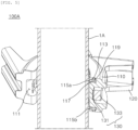
- FIGS. 8A and 8B are a perspective view illustrating an example in which the clamping apparatus for an antenna device according to the first embodiment of the present disclosure has been differently installed and a cross-sectional view of the clamping apparatus.
- a length between an outer end of the upper gear plate 115a at which the gear teeth have been formed and an inner end of the upper gear plate 115a, which is disposed within the horizontal installation slit 117, and a length between an outer end of the lower gear plate 115b at which the gear teeth have been formed and an inner end of the lower gear plate 115b, which is disposed within the horizontal installation slit 117, may be different so that the clamping block body 110 and 120 is tilted and installed.
- a length "L2" of the upper gear plate 115a that is combined with the lower horizontal installation slit 117 is formed to be greater than a length "L1" of the lower gear plate 115b that is combined with the upper horizontal installation slit 117. Accordingly, an angle at which the clamping block body is naturally downward tilted can be maintained because the gear teeth of the upper gear plate 115a further protrude toward an outer circumferential surface of the support pole 1A.
- the length between the inner end and outer end of the upper gear plate 115a may be designed to be greater than the length between the inner end and outer end of the lower gear plate 115b. That is, the lower gear plate 115b that is installed on the lower side of the horizontal installation slit 117 may be installed to have specifications having a length having common specifications. The length between the inner end and outer end of the upper gear plate 115a that is installed on the upper side of the horizontal installation slit 117 may be set to be greater than the length between the inner end and outer end of the lower gear plate 115b.
- the clamping block body 110 and 120 can be tilted and installed at a desired angle by a length by which the upper gear plate 115a has further protruded because the upper gear plate 115a has the length (L2>L1) by which the gear teeth of the upper gear plate more protrude toward the support pole 1A than the gear teeth of the lower gear plate 115b.
- a gear top land that protrudes in a direction toward the outer surface of the support pole 1A and a gear bottom land that is depressed in a direction in which the gear bottom land becomes distant from the outer surface of the support pole 1A are repeated in the gear teeth of the clamping gear plate 115a and 115b.
- a virtual line that connects the front ends of the gear top lands of the gear teeth of the clamping gear plate 115a and 115b may be formed in a shape corresponding to the outer surface of the support pole 1A.
- a technical construction relating to such a shape of the clamping gear plate 115a and 115b may also be applied to second to fourth embodiments 100B to 100D described later without any change.
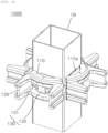
- FIGS. 9 to 11 are perspective views in which clamping apparatuses for an antenna device according to the second to fourth embodiments of the present disclosure have been mounted.
- four clamping block bodies 110 and 120 may be adjacently installed on respective outer surfaces of an outer circumferential surface of the support pole 1B, which has a quadrangle horizontal cross-sectional shape.
- the gear teeth of the clamping gear plate 115a and 115b are formed in a shape that is matched with the support pole 1B having the outer surfaces each having a flat shape.
- three clamping block bodies 110 and 120 may be adjacently installed on respective outer surfaces of an outer circumferential surface of the support pole 1C, which has a triangular horizontal cross-sectional shape.
- the gear teeth of the clamping gear plate 115a and 115b are formed in a shape that is matched with the support pole 1C having the outer surfaces each having a flat shape.
- three clamping block bodies 110 and 120 may be installed on three outer surfaces that are spaced apart from each other, respectively, among the outer surfaces of an outer circumferential surface of the support pole 1D, which has a hexagonal horizontal cross section.
- the gear teeth of the clamping gear plate 115a and 115b may be formed in a shape that is matched with the support pole 1D having the outer surfaces each having a flat shape.
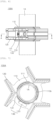
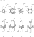
- FIG. 12 is perspective views and horizontal cross-sectional views of the first to fourth embodiments of the present disclosure in FIGS. 1 and 9 to 11 .
- both the size and specifications of the horizontal installation slit 117 that has been formed at an inner end of the edge block 110 in the construction of the clamping block body 110 and 120 are the same.
- only the clamping gear plate 115a and 115b having the gear teeth, which is matched with the horizontal cross-sectional shape of the support poles 1A to 1D may be replaced and installed. Accordingly, there is provided an advantage in that the versatility of replacement and installation can be improved.
- the present disclosure provides the clamping apparatus for an antenna device, by which an antenna device can be universally installed on one support pole having various horizontal cross-sectional shapes and which can prevent a product from being damaged due to a downward slip phenomenon attributable to the weight of the antenna device by being closely attached to the outer surface of the support pole.
Landscapes
- Engineering & Computer Science (AREA)
- General Engineering & Computer Science (AREA)
- Mechanical Engineering (AREA)
- Support Of Aerials (AREA)
Abstract
Description
- The present disclosure relates to a clamping apparatus for an antenna device, and more particularly, to a clamping apparatus for an antenna device, which is provided so that two or more antenna devices are easily installed on an outer circumferential surface of a support pole including horizontal cross sections having various shapes.
- A wireless communication technology, for example, a multiple input multiple output (MIMO) technology, is a technology for significantly increasing a data transmission capacity by using multiple antennas, and is a spatial multiplexing scheme in which a transmitter transmits different data through transmission antennas and a receiver distinguishes between transmission data through proper signal processing.
- Accordingly, more data can be transmitted because a channel capacity may be increased as the numbers of transmission and reception antennas are simultaneously increased. For example, if the number of antennas is increased to 10, a channel capacity that is about 10 times compared to a current single antenna system is secured by using the same frequency band.
- In 4G LTE-advanced, up to 8 antennas are used. In a current pre-5G stage, a product on which 64 or 128 antennas have been mounted is being developed. In 5G, it is expected that base station equipment having a much larger number of antennas will be used. This is called a massive MIMO technology. A current cell operation is 2-dimension. In contrast, if the massive MIMO technology is introduced, 3D-beamforming is made possible and also called full dimension (FD)-MIMO.
- In the massive MIMO technology, as the number of antennas (ANT) is increased, the number of corresponding transmitters and the number of corresponding filters are also increased. Nevertheless, it is practically required to make RF parts (an antenna/filter/power amplifier/transceiver, etc.) small, light-weight, and cheap due to a lease cost for an installation place or a spatial limit of an installation place. Massive MIMO requires a high output for the extension of coverage. Consumption power and the amount of heat generated attributable to such a high output act as a negative factor in reducing a weight and a size.
- In particular, when a MIMO antenna in which modules in which RF elements and digital elements have been implemented are combined as a stack structure is installed in a limited space, there is a need for the compact and small-sized design of a plurality of layers that constitute the MIMO antenna in order to maximize installation easiness or space utilization. There also emerges a need to install multiple antenna devices in one support pole. In this case, there is a need for the design of a universal clamping apparatus corresponding to a horizontal cross-sectional shape of the support pole.
- The present disclosure has been contrived to solve the technical problems, and an object of the present disclosure is to provide a clamping apparatus for an antenna device in which an antenna device can be universally installed in one support pole having various horizontal cross-sectional shapes.
- Furthermore, another object of the present disclosure is to provide a clamping apparatus for an antenna device, which can prevent a product from being damaged due to a downward slip phenomenon attributable to the weight of the antenna device by being closely attached to an outer surface of a support pole.
- Objects of the present disclosure are not limited to the aforementioned object, and the other objects not described above may be evidently understood from the following description by those skilled in the art.
- A clamping apparatus for an antenna device according to an embodiment of the present disclosure includes two or more clamping block bodies each closely attached and combined to occupy a part of an outer surface of a support pole that has extended to be orthogonal to an installation surface thereof, and a clamping band configured to simultaneously penetrate the two or more clamping block bodies, wherein at least some of the clamping band closely attaches and combines the two or more clamping block bodies on the outer surface of the support pole by coming into contact with the outer surface of the support pole.
- In this case, a portion of the clamping band, which corresponds to a portion between the two or more clamping block bodies, may be closely attached to the outer surface of the support pole in a tightening way.
- Furthermore, the horizontal cross-sectional shape of the support pole may include any one of a circle, a triangle, a quadrangle, and a hexagon.
- Furthermore, a clamping gear plate having gear teeth closely attached to the outer surface of the support pole may be detachably provided in each of the two or more clamping block bodies.
- Furthermore, the two or more clamping block bodies may each include an edge block closely attached to the outer surface of the support pole and having an inner end provided with at least one horizontal installation slit for attaching and detaching and installing the clamping gear plate and a connection block in which a medium installation part that is horizontally extended from both ends of the edge block to an outside and mediates an installation of an antenna device has been extended and formed.
- Furthermore, the horizontal installation slit may include two upper horizontal installation slit and lower horizontal installation slit that are spaced apart from each other up and down at an inner end of the edge block adjacent to the outer surface of the support pole.
- Furthermore, the clamping gear plate may include an upper gear plate and a lower gear plate that are installed in the upper horizontal installation slit and the lower horizontal installation slit that have been formed to be spaced apart from each other up and down, respectively.
- Furthermore, a gear top land that protrudes in a direction toward the outer surface of the support pole and a gear bottom land that is depressed in a direction in which the gear bottom land becomes distant from the outer surface of the support pole may be repeated and formed in the gear teeth of the clamping gear plate. A virtual line that connects front ends of the gear top lands of the gear teeth of the clamping gear plate may be formed in a shape corresponding to the outer surface of the support pole.
- Furthermore, a band installation hole that has been penetrated so that the band installation hole has the center of the support pole as a concentric circle for the penetration and combination of the clamping band may be formed in the edge block.
- Furthermore, the clamping band may include a band part configured to penetrate the band installation hole and to closely attach the clamping block body to the support pole upon tightening and fastening and a fixing part configured to fix the band part after generating a predetermined tightening force to the band part.
- Furthermore, the clamping block body may occupy a cross section of a part of the outer surface that is formed by a horizontal cross-sectional shape of the support pole, wherein two or more clamping block bodies may be installed to be adjacent to each other or spaced apart from each other.
- Furthermore, the horizontal cross-sectional shape of the support pole may include any one of a circle, a triangle, a quadrangle, and a hexagon. The remaining external shapes except an end at which the gear teeth of the clamping gear plate have been formed may have an identical shape regardless of the horizontal cross-sectional shape of the support pole.
- Furthermore, a length between an outer end of the upper gear plate at which the gear teeth have been formed and an inner end of the upper gear plate, which is disposed within the horizontal installation slit, and a length between an outer end of the lower gear plate at which the gear teeth have been formed and an inner end of the lower gear plate, which is disposed within the horizontal installation slit, may be different so that the clamping block body is tilted and installed.
- According to the clamping apparatus for an antenna device according to an embodiment of the present disclosure, there is an effect in that installation versatility is improved because the clamping apparatus can be firmly installed in the support pole by replacing the clamping gear plate that is matched with a horizontal cross-sectional shape of the support pole.
-
-
FIG. 1 is a perspective view illustrating a clamping apparatus for an antenna device according to a first embodiment of the present disclosure, -
FIG. 2 is an exploded perspective view ofFIG. 1 , -
FIG. 3 is a perspective view illustrating a form in which a clamping band is installed in a unit clamping block body, among the components ofFIG. 1 , -
FIG. 4 is a perspective view illustrating an installation shape of the unit clamping block body for a support pole using a clamping band, among the components ofFIG. 1 , -
FIG. 5 is a cutaway perspective view illustrating a clamping gear plate which may be replaced and installed in the clamping block body, among the components ofFIG. 1 , -
FIG. 6 is a front view of the clamping apparatus for an antenna device according to the first embodiment of the present disclosure, -
FIG. 7 is a cross-sectional view taken along line A-A inFIG. 6 , -
FIGS. 8A and 8B are a perspective view illustrating an example in which the clamping apparatus for an antenna device according to the first embodiment of the present disclosure has been differently installed and a cross-sectional view of the clamping apparatus, -
FIGS. 9 to 11 are perspective views in which clamping apparatuses for an antenna device according to second to fourth embodiments of the present disclosure have been mounted, and -
FIG. 12 is perspective views and horizontal cross-sectional views of the first to fourth embodiments of the present disclosure inFIGS. 1 and9 to 11 . -
1A to 1D : support pole 100A to 100D: clamping apparatus for antenna device 110, 120: clamping block body 110: edge block 111: band installation hole 113: fixing hole 115a, 115b: clamping gear plate 117: horizontal installation slit 119: fixing member 120: connection block 130: clamping band 131: band part 133: fixing part - Hereinafter, clamping apparatuses for an antenna device according to embodiments of the present disclosure will be described in detail with reference to the accompanying drawings.
- In adding reference numerals to the components of each drawing, it should be noted that the same components have the same reference numerals as much as possible even if they are displayed in different drawings. Furthermore, in describing embodiments of the present disclosure, when it is determined that a detailed description of the related well-known configuration or function hinders understanding of an embodiment of the present disclosure, the detailed description thereof will be omitted.
- Furthermore, in describing components of an embodiment of the present disclosure, terms, such as a first, a second, A, B, (a), and (b), may be used. Such terms are used only to distinguish one component from another component, and the essence, order, or sequence of a corresponding component is not limited by the terms. All terms used herein, including technical or scientific terms, have the same meanings as those commonly understood by a person having ordinary knowledge in the art to which the present disclosure pertains, unless defined otherwise in the specification. Terms, such as those commonly used and defined in dictionaries, should be construed as having the same meanings as those in the context of a related technology, and are not construed as having ideal or excessively formal meanings unless explicitly defined otherwise in the specification.
- Clamping
apparatuses 100A to 100D for an antenna device according to the present disclosure each play a role as a medium that enables multiple antenna devices (not illustrated) to be stably installed at the same height with each ofsupport poles 1A to 1D. - More specifically, the
clamping apparatuses 100A to 100D for an antenna device according to the present disclosure each include aclamping block body support poles 1A to 1D having various horizontal cross sections and aclamping band 130 that fixes theclamping block body support poles 1A to 1D. - In this case, the
clamping block body clamping gear plate support poles 1A to 1D by a tightening force of theclamping band 130 are provided at an inner circumferential end thereof. -
FIG. 1 is a perspective view illustrating a clamping apparatus for an antenna device according to a first embodiment of the present disclosure.FIG. 2 is an exploded perspective view ofFIG. 1 .FIG. 3 is a perspective view illustrating a form in which a clamping band is installed in a unit clamping block body, among the components ofFIG. 1 .FIG. 4 is a perspective view illustrating an installation shape of the unit clamping block body for a support pole using a clamping band, among the components ofFIG. 1 .FIG. 5 is a cutaway perspective view illustrating a clamping gear plate which may be replaced and installed in the clamping block body, among the components ofFIG. 1 .FIG. 6 is a front view of the clamping apparatus for an antenna device according to an embodiment of the present disclosure.FIG. 7 is a cross-sectional view taken along line A-A inFIG. 6 . - The
support pole 1A may be formed to have a circular horizontal cross section in thefirst embodiment 100A, as referred inFIGS. 1 to 7 . Two or moreclamping block bodies support pole 1A. - For example, the clamping block bodies may be installed in the
support pole 1A to be spaced apart from each other at an angle at which the clamping block bodies do not mutually influence beam tilting and steering operations of an antenna device. Two clampingblock bodies block bodies support pole 1A. Thefirst embodiment 100A of the present disclosure exemplifies that three clampingblock bodies 110A-1, 110A-2, and 110A-3 have been installed on an outer circumferential surface of thesupport pole 1A at intervals of 120 degrees. However, four clamping block bodies may be adjacently installed at intervals of 90 degrees because two or moreclamping block bodies - In this case, as referred in
FIGS. 1 to 7 , theclamping block body support pole 1A, and may include anedge block 110 in which at least one horizontal installation slit 117 for the attachment and detachment and installation of aclamping gear plate edge block 110 to the outside horizontally and in which a medium installation part (not illustrated) that mediates the installation of an antenna device (not illustrated) has been extended and formed. - An outward appearance of the
edge block 110 and theconnection block 120 is formed to have a common shape and size regardless of a shape of each of thesupport poles 1A to 1D. As described later, only theclamping gear plate support poles 1A to 1D. This will be described more specifically later. - Meanwhile, a separate structure for the installation and fixing of the
clamping block body support pole 1A, and thesupport pole 1A may be installed with a sufficient clamping force through only theclamping band 130. - More specifically, as referred in
FIGS. 1 to 7 , theclamping band 130 may include aband part 131 that penetrates and combines theclamping block body part 133 that is fixed after generating a predetermined tightening force to theband part 131. - In this case, the
clamping band 130 simultaneously penetrates multipleclamping block bodies clamping block bodies support pole 1A as at least some of the clamping band comes into contact with the outer surface of thesupport pole 1A. - A portion of the
clamping band 130, which corresponds to a portion between the two or moreclamping block bodies support pole 1A in a tightening way. - A
band installation hole 111 that has been penetrated to have the center of thesupport pole 1A as a concentric circle for the penetration and combination of theclamping band 130 may be formed in theedge block 110 in the construction of theclamping block body - The
band installation hole 111 may be preferably formed in a form in which the band installation hole penetrates the connection block 120 that has been extended and formed from theedge block 110. Theband part 131 of theclamping band 130 may be closely attached to an outer surface of theedge block 110 and tightened and combined therewith at a predetermined tightening force. - In this case, the
band installation hole 111 is formed to penetrate multiple edge blocks 110, but may be formed to penetrate the multiple edge blocks by using the center of thesupport pole 1A as a concentric circle. - After the
band part 131 of theclamping band 130 is combined to penetrate the band installation holes 111 of two or moreclamping block bodies part 133. Accordingly, when theclamping gear plate support pole 1A and tightens the support pole while forming a friction force, the two or moreclamping block bodies support pole 1A simultaneously. - Meanwhile, two horizontal installation slits 117 formed at inner ends of the
edge block 110, which are portions adjacent to the outer surface of thesupport pole 1A, in the construction of theclamping block body clamping gear plate upper gear plate 115a and alower gear plate 115b that are installed in the two horizontal installation slits 117, respectively, which have been formed to be spaced apart from each other up and down. In this case, the horizontal installation slit 117 that has been formed in a relatively upper part is referred to as an "upper horizontal installation slit". The horizontal installation slit 117 that has been formed in a relatively lower part is referred to as a "lower horizontal installation slit". - Furthermore, both the upper horizontal installation slit and lower horizontal installation slit 117 may be formed to have the same shape and size (including a depth) regardless of a shape of the gear teeth of the
clamping gear plate clamping gear plate support poles 1A to 1D that is installed, the upper horizontal installation slit and lower horizontal installation slit 117 have the same specifications. There is an advantage in that versatility can be improved. - In this case, a fixing
hole 113 for fixing theclamping gear plate member 119 may be formed at the bottom of theedge block 110 in which the horizontal installation slit 117 has been formed. Furthermore, although not illustrated, a locking part that is caught by theclamping gear plate edge block 110 in which the horizontal installation slit 117 has been formed and that prevents theclamping gear plate edge block 110. - Meanwhile, in general, it is preferred that each of the clamping
apparatuses 100A to 100D for an antenna device according to the present disclosure needs to be made light-weighted and manufactured by considering that an antenna device having a relatively heavy weight has to be installed in each of thesupport poles 1A to 1D corresponding to a high location from the ground. - For example, the
clamping gear plate support poles 1A to 1D. Accordingly, an advantage in that an overall product can be made light-weighted by adopting a material that constitutes theedge block 110 and the connection block 120 which occupy a relatively large volume and that has a smaller weight and hardness than those of theclamping gear plate -
FIGS. 8A and 8B are a perspective view illustrating an example in which the clamping apparatus for an antenna device according to the first embodiment of the present disclosure has been differently installed and a cross-sectional view of the clamping apparatus. - As referred in
FIGS. 8A and 8B , in the clamping apparatus for an antenna device according to the first embodiment of the present disclosure, a length between an outer end of theupper gear plate 115a at which the gear teeth have been formed and an inner end of theupper gear plate 115a, which is disposed within the horizontal installation slit 117, and a length between an outer end of thelower gear plate 115b at which the gear teeth have been formed and an inner end of thelower gear plate 115b, which is disposed within the horizontal installation slit 117, may be different so that theclamping block body - More specifically, referring to
FIG. 8B , in the state in which both the depths of the horizontal installation slit 117 at an upper part and lower part thereof are the same, a length "L2" of theupper gear plate 115a that is combined with the lower horizontal installation slit 117 is formed to be greater than a length "L1" of thelower gear plate 115b that is combined with the upperhorizontal installation slit 117. Accordingly, an angle at which the clamping block body is naturally downward tilted can be maintained because the gear teeth of theupper gear plate 115a further protrude toward an outer circumferential surface of thesupport pole 1A. - For example, if the
clamping block body support pole 1A, the length between the inner end and outer end of theupper gear plate 115a may be designed to be greater than the length between the inner end and outer end of thelower gear plate 115b. That is, thelower gear plate 115b that is installed on the lower side of the horizontal installation slit 117 may be installed to have specifications having a length having common specifications. The length between the inner end and outer end of theupper gear plate 115a that is installed on the upper side of the horizontal installation slit 117 may be set to be greater than the length between the inner end and outer end of thelower gear plate 115b. Accordingly, theclamping block body upper gear plate 115a has further protruded because theupper gear plate 115a has the length (L2>L1) by which the gear teeth of the upper gear plate more protrude toward thesupport pole 1A than the gear teeth of thelower gear plate 115b. - Meanwhile, a gear top land that protrudes in a direction toward the outer surface of the
support pole 1A and a gear bottom land that is depressed in a direction in which the gear bottom land becomes distant from the outer surface of thesupport pole 1A are repeated in the gear teeth of theclamping gear plate clamping gear plate support pole 1A. - A technical construction relating to such a shape of the
clamping gear plate fourth embodiments 100B to 100D described later without any change. -
FIGS. 9 to 11 are perspective views in which clamping apparatuses for an antenna device according to the second to fourth embodiments of the present disclosure have been mounted. - Referring to
FIG. 9 , as thesecond embodiment 100B, four clampingblock bodies support pole 1B, which has a quadrangle horizontal cross-sectional shape. - In this case, it is preferred that the gear teeth of the
clamping gear plate support pole 1B having the outer surfaces each having a flat shape. - Meanwhile, referring to
FIG. 10 , as thethird embodiment 100C, three clampingblock bodies support pole 1C, which has a triangular horizontal cross-sectional shape. - In this case, it is preferred that the gear teeth of the
clamping gear plate support pole 1C having the outer surfaces each having a flat shape. - Furthermore, referring to
FIG. 11 , as thefourth embodiment 100D, three clampingblock bodies support pole 1D, which has a hexagonal horizontal cross section. - Even in this case, likewise, the gear teeth of the
clamping gear plate support pole 1D having the outer surfaces each having a flat shape. -
FIG. 12 is perspective views and horizontal cross-sectional views of the first to fourth embodiments of the present disclosure inFIGS. 1 and9 to 11 . - Referring to
FIG. 12 , both the size and specifications of the horizontal installation slit 117 that has been formed at an inner end of theedge block 110 in the construction of theclamping block body clamping gear plate support poles 1A to 1D may be replaced and installed. Accordingly, there is provided an advantage in that the versatility of replacement and installation can be improved. - The clamping apparatus for an antenna device according to the embodiments of the present disclosure has been described in detail with reference to the accompanying drawings. However, an embodiment of the present disclosure is not essentially limited to the aforementioned embodiment, and may include various modifications and implementations within an equivalent range thereof by a person having ordinary knowledge in the art to which the present disclosure pertains. Accordingly, the true range of a right of the present disclosure will be said to be defined by the appended claims.
- The present disclosure provides the clamping apparatus for an antenna device, by which an antenna device can be universally installed on one support pole having various horizontal cross-sectional shapes and which can prevent a product from being damaged due to a downward slip phenomenon attributable to the weight of the antenna device by being closely attached to the outer surface of the support pole.
Claims (13)
- A clamping apparatus for an antenna device, comprising:two or more clamping block bodies each closely attached and combined to occupy some of an outer surface of a support pole that has extended to be orthogonal to an installation surface thereof; anda clamping band configured to simultaneously penetrate the two or more clamping block bodies, wherein at least some of the clamping band closely attaches and combines the two or more clamping block bodies on the outer surface of the support pole by coming into contact with the outer surface of the support pole.
- The clamping apparatus of claim 1, wherein a portion of the clamping band, which corresponds to a portion between the two or more clamping block bodies, is closely attached to the outer surface of the support pole in a tightening way.
- The clamping apparatus of claim 1, wherein the horizontal cross-sectional shape of the support pole comprises any one of a circle, a triangle, a quadrangle, and a hexagon.
- The clamping apparatus of claim 1, wherein a clamping gear plate having gear teeth closely attached to the outer surface of the support pole is detachably provided in each of the two or more clamping block bodies.
- The clamping apparatus of claim 4, wherein the two or more clamping block bodies each comprise:an edge block closely attached to the outer surface of the support pole and having an inner end provided with at least one horizontal installation slit for attaching and detaching and installing the clamping gear plate; anda connection block in which a medium installation part that is horizontally extended from both ends of the edge block to an outside and mediates an installation of an antenna device has been extended and formed.
- The clamping apparatus of claim 5, wherein the horizontal installation slit comprises two upper horizontal installation slit and lower horizontal installation slit that are spaced apart from each other up and down at an inner end of the edge block adjacent to the outer surface of the support pole.
- The clamping apparatus of claim 6, wherein the clamping gear plate comprises an upper gear plate and a lower gear plate that are installed in the upper horizontal installation slit and the lower horizontal installation slit that have been formed to be spaced apart from each other up and down, respectively.
- The clamping apparatus of claim 4, wherein:a gear top land that protrudes in a direction toward the outer surface of the support pole and a gear bottom land that is depressed in a direction in which the gear bottom land becomes distant from the outer surface of the support pole are repeated and formed in the gear teeth of the clamping gear plate, anda virtual line that connects front ends of the gear top lands of the gear teeth of the clamping gear plate is formed in a shape corresponding to the outer surface of the support pole.
- The clamping apparatus of claim 2, wherein a band installation hole that has been penetrated so that the band installation hole has a center of the support pole as a concentric circle for a penetration and combination of the clamping band is formed in the edge block.
- The clamping apparatus of claim 9, wherein the clamping band comprises:a band part configured to penetrate the band installation hole and to closely attach the clamping block body to the support pole upon tightening and fastening; anda fixing part configured to fix the band part after generating a predetermined tightening force to the band part.
- The clamping apparatus of claim 1, wherein the clamping block body occupies a cross section of a part of the outer surface that is formed by a horizontal cross-sectional shape of the support pole, wherein two or more clamping block bodies are installed to be adjacent to each other or spaced apart from each other.
- The clamping apparatus of claim 4, wherein:the horizontal cross-sectional shape of the support pole comprises any one of a circle, a triangle, a quadrangle, and a hexagon, andremaining external shapes except an end at which the gear teeth of the clamping gear plate have been formed have an identical shape regardless of the horizontal cross-sectional shape of the support pole.
- The clamping apparatus of claim 7, wherein a length between an outer end of the upper gear plate at which the gear teeth have been formed and an inner end of the upper gear plate, which is disposed within the horizontal installation slit, and a length between an outer end of the lower gear plate at which the gear teeth have been formed and an inner end of the lower gear plate, which is disposed within the horizontal installation slit, are different so that the clamping block body is tilted and installed.
Applications Claiming Priority (3)
| Application Number | Priority Date | Filing Date | Title |
|---|---|---|---|
| KR20210126742 | 2021-09-24 | ||
| KR1020220119784A KR20230043746A (en) | 2021-09-24 | 2022-09-22 | Clamping apparatus for antenna device |
| PCT/KR2022/014218 WO2023048491A1 (en) | 2021-09-24 | 2022-09-23 | Clamping apparatus for antenna device |
Publications (2)
| Publication Number | Publication Date |
|---|---|
| EP4407792A1 true EP4407792A1 (en) | 2024-07-31 |
| EP4407792A4 EP4407792A4 (en) | 2025-10-08 |
Family
ID=85720925
Family Applications (1)
| Application Number | Title | Priority Date | Filing Date |
|---|---|---|---|
| EP22873195.6A Pending EP4407792A4 (en) | 2021-09-24 | 2022-09-23 | CLAMPING DEVICE FOR AN ANTENNA DEVICE |
Country Status (4)
| Country | Link |
|---|---|
| US (1) | US12542344B2 (en) |
| EP (1) | EP4407792A4 (en) |
| JP (1) | JP7724955B2 (en) |
| WO (1) | WO2023048491A1 (en) |
Family Cites Families (28)
| Publication number | Priority date | Publication date | Assignee | Title |
|---|---|---|---|---|
| US1653083A (en) * | 1926-08-16 | 1927-12-20 | Sadie H Blaw | Flag holder |
| US3241800A (en) * | 1963-12-11 | 1966-03-22 | Gen Plastics Corp | Mounting device |
| US4466589A (en) * | 1981-08-24 | 1984-08-21 | Diamond Communication Products, Inc. | Cable television tap bracket or the like |
| US6109577A (en) * | 1998-03-02 | 2000-08-29 | Aluma-Form, Inc. | Flexible banding and instrument support system |
| US6378820B1 (en) * | 1998-11-05 | 2002-04-30 | Mooney & Company | Apparatus and method for mounting banners |
| KR200262261Y1 (en) * | 2001-10-16 | 2002-03-18 | 한양프레임주식회사 | Supporting structure of sign board |
| JP2003152409A (en) * | 2001-11-13 | 2003-05-23 | Matsushita Electric Ind Co Ltd | Antenna mounting device |
| US6969034B2 (en) * | 2003-08-07 | 2005-11-29 | Musco Corporation | Enclosure box attachment apparatus, system, and method |
| US9200654B1 (en) * | 2008-01-28 | 2015-12-01 | Pelco Products, Inc. | Mounting bracket for traffic control device |
| CN101634393B (en) * | 2008-07-25 | 2014-04-16 | 华为技术有限公司 | Combination structure of mounting parts, main fasteners and communication equipment and mounting parts |
| KR200456433Y1 (en) * | 2009-08-03 | 2011-10-31 | 주식회사 감마누 | Mounting apparatus of speaker type disguised antenna |
| CN102691868B (en) * | 2012-05-28 | 2014-03-05 | 华为技术有限公司 | Mounting part and modules |
| KR101440927B1 (en) * | 2013-09-11 | 2014-09-17 | 권봉겸 | Clamp reinforcing apparatus for traffic sign |
| US9853346B2 (en) * | 2015-01-19 | 2017-12-26 | Commscope Technologies Llc | High capacity sector mount |
| US10679529B1 (en) * | 2016-02-18 | 2020-06-09 | Balloon Innovations Inc. | Modular pole display assembly |
| US10588305B2 (en) * | 2016-07-20 | 2020-03-17 | Harold F. Larkin | Marine hub with interchangeable arms |
| SE540650C2 (en) * | 2016-09-22 | 2018-10-09 | Cue Dee Ab | Chain clamp |
| US11222558B2 (en) * | 2018-03-08 | 2022-01-11 | Balloon Innovations, Inc. | Modular advertising system |
| US10774979B2 (en) * | 2019-01-22 | 2020-09-15 | Joseph Lombardi | Multi-clamp stand apparatus |
| CN111720710B (en) * | 2019-03-21 | 2022-04-08 | 上海诺基亚贝尔股份有限公司 | Connecting structure |
| US11326666B2 (en) * | 2019-04-23 | 2022-05-10 | ConcealFab Corporation | Low-PIM rod receiver angle adapters and cable hanger assemblies |
| EP3998677B1 (en) * | 2019-07-05 | 2025-12-10 | KMW Inc. | Clamping apparatus for antenna |
| WO2021050316A1 (en) * | 2019-09-11 | 2021-03-18 | Commscope Technologies Llc | Isolator for mounting cable hangers |
| CN112747225A (en) * | 2019-10-29 | 2021-05-04 | 华为技术有限公司 | Staple bolt and electronic equipment |
| WO2021091809A1 (en) * | 2019-11-05 | 2021-05-14 | Concealfab Corp. | Low-pim universal cable hanger system |
| WO2021125829A1 (en) * | 2019-12-20 | 2021-06-24 | 삼성전자 주식회사 | Adjustable communication equipment assembly structure and apparatus including same |
| EP4292168A4 (en) * | 2021-02-15 | 2025-01-01 | ConcealFab, Inc. | Low-pim multi-function mounting system |
| US11901607B2 (en) * | 2021-07-12 | 2024-02-13 | Commscope Technologies Llc | Mounting assembly for a base station antenna |
-
2022
- 2022-09-23 WO PCT/KR2022/014218 patent/WO2023048491A1/en not_active Ceased
- 2022-09-23 EP EP22873195.6A patent/EP4407792A4/en active Pending
- 2022-09-23 JP JP2024515887A patent/JP7724955B2/en active Active
-
2024
- 2024-03-12 US US18/602,144 patent/US12542344B2/en active Active
Also Published As
| Publication number | Publication date |
|---|---|
| US12542344B2 (en) | 2026-02-03 |
| JP2024531691A (en) | 2024-08-29 |
| US20240250402A1 (en) | 2024-07-25 |
| EP4407792A4 (en) | 2025-10-08 |
| JP7724955B2 (en) | 2025-08-18 |
| WO2023048491A1 (en) | 2023-03-30 |
Similar Documents
| Publication | Publication Date | Title |
|---|---|---|
| JP7285341B2 (en) | antenna device | |
| US6836254B2 (en) | Antenna system | |
| US12095138B2 (en) | Clamping apparatus for antenna | |
| US9935379B2 (en) | Communication system node comprising a re-configuration network | |
| KR101609665B1 (en) | Antenna of mobile communication station | |
| EP2865049B1 (en) | Antenna radome with removeably connected electronics module | |
| US9014068B2 (en) | Antenna having active and passive feed networks | |
| KR100978878B1 (en) | Cellular signal enhancer | |
| US20090251378A1 (en) | Device and Method for Modular antenna Formation and Configuration | |
| AU2159200A (en) | Circular direction finding antenna | |
| US20250323406A1 (en) | Base station antennas having an active antenna module(s) and related mounting systems and methods | |
| US9774098B2 (en) | Wireless communication node with 4TX/4RX triple band antenna arrangement | |
| JP2016510563A (en) | Antenna configuration for multiple frequency band operation | |
| CN102369635A (en) | Panel antenna having sealed radio enclosure | |
| US11012107B2 (en) | Antenna system | |
| EP4407792A1 (en) | Clamping apparatus for antenna device | |
| KR20230043746A (en) | Clamping apparatus for antenna device | |
| KR200494771Y1 (en) | Multiple Input Multiple Output Antennas and Systems | |
| IT202100014927A1 (en) | SYSTEMS AND METHODS FOR GENERATION OF CALIBRATION DATA IN ACTIVE ANTENNA MODULES HAVING INSIDE ANTENNA-SIDE ARRAYS OF FILTERS | |
| EP4016730B1 (en) | Base station antenna and board assembly for base station antenna | |
| CN118435453A (en) | Clamping device for antenna equipment | |
| KR20210037505A (en) | Quadruple polarized antenna module with time-polarization separation | |
| EP1814197B1 (en) | An antenna arrangement having unevenly separated elements | |
| US20230110480A1 (en) | Mounting brackets, filter units configured to couple to the mounting brackets and related methods |
Legal Events
| Date | Code | Title | Description |
|---|---|---|---|
| STAA | Information on the status of an ep patent application or granted ep patent |
Free format text: STATUS: THE INTERNATIONAL PUBLICATION HAS BEEN MADE |
|
| PUAI | Public reference made under article 153(3) epc to a published international application that has entered the european phase |
Free format text: ORIGINAL CODE: 0009012 |
|
| STAA | Information on the status of an ep patent application or granted ep patent |
Free format text: STATUS: REQUEST FOR EXAMINATION WAS MADE |
|
| 17P | Request for examination filed |
Effective date: 20240320 |
|
| AK | Designated contracting states |
Kind code of ref document: A1 Designated state(s): AL AT BE BG CH CY CZ DE DK EE ES FI FR GB GR HR HU IE IS IT LI LT LU LV MC MK MT NL NO PL PT RO RS SE SI SK SM TR |
|
| DAV | Request for validation of the european patent (deleted) | ||
| DAX | Request for extension of the european patent (deleted) | ||
| A4 | Supplementary search report drawn up and despatched |
Effective date: 20250908 |
|
| RIC1 | Information provided on ipc code assigned before grant |
Ipc: H01Q 1/12 20060101AFI20250902BHEP Ipc: F16B 2/08 20060101ALI20250902BHEP Ipc: F16M 13/02 20060101ALI20250902BHEP |