EP4407774A1 - Battery cell unit, and battery pack and vehicle including same - Google Patents
Battery cell unit, and battery pack and vehicle including same Download PDFInfo
- Publication number
- EP4407774A1 EP4407774A1 EP23843375.9A EP23843375A EP4407774A1 EP 4407774 A1 EP4407774 A1 EP 4407774A1 EP 23843375 A EP23843375 A EP 23843375A EP 4407774 A1 EP4407774 A1 EP 4407774A1
- Authority
- EP
- European Patent Office
- Prior art keywords
- battery cell
- cell
- pouch
- cover
- battery
- Prior art date
- Legal status (The legal status is an assumption and is not a legal conclusion. Google has not performed a legal analysis and makes no representation as to the accuracy of the status listed.)
- Granted
Links
Images




Classifications
-
- H—ELECTRICITY
- H01—ELECTRIC ELEMENTS
- H01M—PROCESSES OR MEANS, e.g. BATTERIES, FOR THE DIRECT CONVERSION OF CHEMICAL ENERGY INTO ELECTRICAL ENERGY
- H01M50/00—Constructional details or processes of manufacture of the non-active parts of electrochemical cells other than fuel cells, e.g. hybrid cells
- H01M50/10—Primary casings; Jackets or wrappings
- H01M50/102—Primary casings; Jackets or wrappings characterised by their shape or physical structure
- H01M50/105—Pouches or flexible bags
-
- H—ELECTRICITY
- H01—ELECTRIC ELEMENTS
- H01M—PROCESSES OR MEANS, e.g. BATTERIES, FOR THE DIRECT CONVERSION OF CHEMICAL ENERGY INTO ELECTRICAL ENERGY
- H01M50/00—Constructional details or processes of manufacture of the non-active parts of electrochemical cells other than fuel cells, e.g. hybrid cells
- H01M50/10—Primary casings; Jackets or wrappings
- H01M50/147—Lids or covers
- H01M50/148—Lids or covers characterised by their shape
-
- H—ELECTRICITY
- H01—ELECTRIC ELEMENTS
- H01M—PROCESSES OR MEANS, e.g. BATTERIES, FOR THE DIRECT CONVERSION OF CHEMICAL ENERGY INTO ELECTRICAL ENERGY
- H01M50/00—Constructional details or processes of manufacture of the non-active parts of electrochemical cells other than fuel cells, e.g. hybrid cells
- H01M50/10—Primary casings; Jackets or wrappings
- H01M50/147—Lids or covers
- H01M50/155—Lids or covers characterised by the material
- H01M50/157—Inorganic material
- H01M50/159—Metals
-
- H—ELECTRICITY
- H01—ELECTRIC ELEMENTS
- H01M—PROCESSES OR MEANS, e.g. BATTERIES, FOR THE DIRECT CONVERSION OF CHEMICAL ENERGY INTO ELECTRICAL ENERGY
- H01M50/00—Constructional details or processes of manufacture of the non-active parts of electrochemical cells other than fuel cells, e.g. hybrid cells
- H01M50/30—Arrangements for facilitating escape of gases
- H01M50/35—Gas exhaust passages comprising elongated, tortuous or labyrinth-shaped exhaust passages
- H01M50/358—External gas exhaust passages located on the battery cover or case
-
- H—ELECTRICITY
- H01—ELECTRIC ELEMENTS
- H01M—PROCESSES OR MEANS, e.g. BATTERIES, FOR THE DIRECT CONVERSION OF CHEMICAL ENERGY INTO ELECTRICAL ENERGY
- H01M50/00—Constructional details or processes of manufacture of the non-active parts of electrochemical cells other than fuel cells, e.g. hybrid cells
- H01M50/30—Arrangements for facilitating escape of gases
- H01M50/35—Gas exhaust passages comprising elongated, tortuous or labyrinth-shaped exhaust passages
- H01M50/367—Internal gas exhaust passages forming part of the battery cover or case; Double cover vent systems
-
- H—ELECTRICITY
- H01—ELECTRIC ELEMENTS
- H01M—PROCESSES OR MEANS, e.g. BATTERIES, FOR THE DIRECT CONVERSION OF CHEMICAL ENERGY INTO ELECTRICAL ENERGY
- H01M50/00—Constructional details or processes of manufacture of the non-active parts of electrochemical cells other than fuel cells, e.g. hybrid cells
- H01M50/30—Arrangements for facilitating escape of gases
- H01M50/383—Flame arresting or ignition-preventing means
-
- H—ELECTRICITY
- H01—ELECTRIC ELEMENTS
- H01M—PROCESSES OR MEANS, e.g. BATTERIES, FOR THE DIRECT CONVERSION OF CHEMICAL ENERGY INTO ELECTRICAL ENERGY
- H01M50/00—Constructional details or processes of manufacture of the non-active parts of electrochemical cells other than fuel cells, e.g. hybrid cells
- H01M50/30—Arrangements for facilitating escape of gases
- H01M50/394—Gas-pervious parts or elements
-
- H—ELECTRICITY
- H01—ELECTRIC ELEMENTS
- H01M—PROCESSES OR MEANS, e.g. BATTERIES, FOR THE DIRECT CONVERSION OF CHEMICAL ENERGY INTO ELECTRICAL ENERGY
- H01M50/00—Constructional details or processes of manufacture of the non-active parts of electrochemical cells other than fuel cells, e.g. hybrid cells
- H01M50/50—Current conducting connections for cells or batteries
- H01M50/502—Interconnectors for connecting terminals of adjacent batteries; Interconnectors for connecting cells outside a battery casing
-
- H—ELECTRICITY
- H01—ELECTRIC ELEMENTS
- H01M—PROCESSES OR MEANS, e.g. BATTERIES, FOR THE DIRECT CONVERSION OF CHEMICAL ENERGY INTO ELECTRICAL ENERGY
- H01M2220/00—Batteries for particular applications
- H01M2220/20—Batteries in motive systems, e.g. vehicle, ship, plane
-
- H—ELECTRICITY
- H01—ELECTRIC ELEMENTS
- H01M—PROCESSES OR MEANS, e.g. BATTERIES, FOR THE DIRECT CONVERSION OF CHEMICAL ENERGY INTO ELECTRICAL ENERGY
- H01M50/00—Constructional details or processes of manufacture of the non-active parts of electrochemical cells other than fuel cells, e.g. hybrid cells
- H01M50/20—Mountings; Secondary casings or frames; Racks, modules or packs; Suspension devices; Shock absorbers; Transport or carrying devices; Holders
- H01M50/204—Racks, modules or packs for multiple batteries or multiple cells
- H01M50/207—Racks, modules or packs for multiple batteries or multiple cells characterised by their shape
- H01M50/211—Racks, modules or packs for multiple batteries or multiple cells characterised by their shape adapted for pouch cells
-
- H—ELECTRICITY
- H01—ELECTRIC ELEMENTS
- H01M—PROCESSES OR MEANS, e.g. BATTERIES, FOR THE DIRECT CONVERSION OF CHEMICAL ENERGY INTO ELECTRICAL ENERGY
- H01M50/00—Constructional details or processes of manufacture of the non-active parts of electrochemical cells other than fuel cells, e.g. hybrid cells
- H01M50/20—Mountings; Secondary casings or frames; Racks, modules or packs; Suspension devices; Shock absorbers; Transport or carrying devices; Holders
- H01M50/249—Mountings; Secondary casings or frames; Racks, modules or packs; Suspension devices; Shock absorbers; Transport or carrying devices; Holders specially adapted for aircraft or vehicles, e.g. cars or trains
-
- Y—GENERAL TAGGING OF NEW TECHNOLOGICAL DEVELOPMENTS; GENERAL TAGGING OF CROSS-SECTIONAL TECHNOLOGIES SPANNING OVER SEVERAL SECTIONS OF THE IPC; TECHNICAL SUBJECTS COVERED BY FORMER USPC CROSS-REFERENCE ART COLLECTIONS [XRACs] AND DIGESTS
- Y02—TECHNOLOGIES OR APPLICATIONS FOR MITIGATION OR ADAPTATION AGAINST CLIMATE CHANGE
- Y02E—REDUCTION OF GREENHOUSE GAS [GHG] EMISSIONS, RELATED TO ENERGY GENERATION, TRANSMISSION OR DISTRIBUTION
- Y02E60/00—Enabling technologies; Technologies with a potential or indirect contribution to GHG emissions mitigation
- Y02E60/10—Energy storage using batteries
Definitions
- the present disclosure relates to a battery cell unit, and a battery pack and a vehicle including the same, and more particularly, to a battery cell unit with improved stability, and a battery pack and a vehicle including the battery cell unit.
- Nickel cadmium batteries or nickel hydride batteries have been widely used as conventional secondary batteries, but recently, lithium secondary batteries, which have almost no memory effect compared to nickel-based secondary batteries and thus have advantages of free charge/discharge, very low self-discharge rate, and high energy density, have been widely used.
- a lithium secondary battery mainly uses a lithium-based oxide and a carbon material as a positive electrode active material and a negative electrode active material, respectively.
- a lithium secondary battery includes an electrode assembly in which a positive electrode plate and a negative electrode plate coated with a positive electrode active material and a negative electrode active material are located with a separator therebetween, and a casing in which the electrode assembly is air-tightly accommodated together with an electrolyte, that is, a battery case.
- secondary batteries may be classified into can-type batteries in which an electrode assembly is received in a metal can, and pouch-type batteries in which an electrode assembly is received in a pouch of an aluminum laminate sheet.
- a conventional battery pack includes one or more battery modules and a control unit for controlling charging and discharging of the battery pack in a pack case.
- the battery module includes a plurality of battery cells in a module case.
- a plurality of battery cells are accommodated in a module case to constitute each battery module, and one or more battery modules are accommodated in a pack case to constitute a battery pack.
- pouch-type batteries have various advantages of light weight and small dead space when stacked, but are vulnerable to external impact and have poor assemblability. Accordingly, it is common to manufacture a battery pack by first modularizing a plurality of cells and then accommodating the plurality of cells in a pack case.
- Safety is one of the most important issues in such a battery pack configuration.
- a thermal event occurs in any one of a plurality of battery cells included in a battery pack, it is necessary to prevent propagation of the thermal event to other battery cells.
- the ignition or explosion of the battery pack may cause great damage to surrounding people or property. Accordingly, in such a battery pack, a configuration capable of appropriately controlling a thermal event is required.
- the present disclosure is designed to solve the problems of the related art, and therefore the present disclosure is directed to providing a battery cell unit configured to, when a thermal event occurs in a battery cell, prevent flames, sparks, venting gas, etc. ejected from the battery cell from propagating to other surrounding battery cells and discharge venting gas in a specific direction to reduce internal pressure, and a battery pack and a vehicle including the battery cell unit.
- a battery cell unit including a pouch-type battery cell, and a cell cover provided to at least partially surround the pouch-type battery cell, wherein the cell cover is configured to be spaced apart from the pouch-type battery cell and includes a particle pocket portion configured to collect particles ejected from the pouch-type battery cell when a thermal event occurs.
- the cell cover may be configured to cover both side surfaces and an upper side of the pouch-type battery cell, and the particle pocket portion may be formed on an upper side of the cell cover.
- the particle pocket portion may be formed on the upper side of the cell cover so that both side portions along a width direction of the cell cover protrude more upward than a central portion.
- a mesh member may be formed inside the particle pocket portion.
- the mesh member may be formed by overlapping several porous metal plates.
- a directional venting unit may be formed in the cell cover to guide venting gas to be discharged in a preset direction.
- the battery cell unit may include a thermal resin coupled to the cell cover, wherein the cell cover includes a portion to which the thermal resin is coupled and a portion to which the thermal resin is not coupled, wherein the directional venting unit includes a gas outlet formed in the portion of the cell cover to which the thermal resin is not coupled, and a movement path formed between the pouch-type battery cell and the cell cover.
- the gas outlet may be formed in a lower portion of the cell cover.
- the cell cover may be configured to support a state where a plurality of pouch-type battery cells are stacked.
- the cell cover may be formed in an 'n' shape.
- the cell cover may be formed of a metal material.
- the battery pack may further include a bus bar configured to connect a plurality of electrode leads.
- the cell cover may be configured to partially surround the pouch-type battery cell so that at least one side of the surrounded pouch-type battery cell is exposed to outside.
- a battery pack including the battery cell unit described above and a pack case having an inner space in which the battery cell unit is accommodated.
- the cell cover may be configured so that at least one side of the surrounded pouch-type battery cell is exposed toward a bottom surface of the battery pack.
- the cell cover may be directly seated on the pack case.
- a vehicle including the battery cell unit described above.
- a thermal event occurs in a battery cell
- flames, sparks, venting gas, etc. ejected from the battery cell may be prevented from propagating to other surrounding battery cells, and structural collapse of a cell assembly may be prevented by discharging venting gas to suppress a rapid pressure increase.
- the present disclosure may have various other effects, which will be described in each embodiment, or descriptions of effects that may be easily inferred by one of ordinary skill in the art will be omitted.
- each element or a specific portion of the element shown in the drawings may be exaggerated, omitted or schematically drawn for the purpose of convenience and clarity of explanation. Accordingly, the size of each element may not substantially reflect its actual size. While describing the present disclosure, detailed descriptions of related well-known functions or configurations that may blur the points of the present disclosure are omitted.
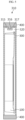
- FIGS. 1 to 3 are views illustrating a process of coupling a cell cover to a pouch-type battery cell in a battery cell unit and connecting two pouch-type battery cells to a bus bar according to an embodiment of the present disclosure.
- FIG. 4 is an exploded perspective view illustrating a pouch-type battery cell and a cell cover provided in a battery cell unit according to an embodiment of the present disclosure.
- FIG. 5 is a cross-sectional view illustrating a state where the pouch-type battery cell and the cell cover of FIG. 4 are coupled to each other.
- FIG. 6 is a partial perspective view illustrating a state where the pouch-type battery cell and the cell cover of FIG. 4 are coupled to each other, particularly illustrating a gas outlet.
- FIG. 7 is a side cross-sectional view illustrating a state where the pouch-type battery cell and the cell cover of FIG. 4 are coupled to each other, particularly illustrating a directional venting unit that is a gas exhaust path.
- a battery cell unit 15 includes a pouch-type battery cell 100 and a cell cover 300.
- the pouch-type battery cell 100 that is a pouch-type secondary battery may include an electrode assembly, an electrolyte, and a pouch casing.
- a plurality of pouch-type battery cells 100 may be included in a battery module (not shown) or a battery pack 10 (see FIG. 8 ). Also, the plurality of pouch-type battery cells 100 may be stacked in at least one direction.
- the cell cover 300 may be provided to at least partially surround the pouch-type battery cell 100.
- the cell cover 300 may be configured to surround both side surfaces and an upper side of at least some pouch-type battery cells 100.
- the present disclosure is not limited thereto.
- the cell cover 300 may be configured to partially surround the pouch-type battery cell 100 so that at least one side of the surrounded pouch-type battery cell 100 is exposed to the outside.
- the cell cover 300 may be configured to support the pouch-type battery cell 100 in an upright state. In general, it is not easy to stack the pouch-type battery cells 100 in a vertical direction. However, the cell cover 300 provided in the battery cell unit 15 according to the present disclosure may be configured to surround one or more pouch-type battery cells 100 and maintain the surrounded battery cells 100 in an upright state, that is, an erected state.
- the cell cover 300 may be configured to surround a various number of pouch-type battery cells 100 together.
- one cell cover 300 may be configured to surround one pouch-type battery cell 100.
- the cell cover 300 may be configured to surround two pouch-type battery cells 100 together, or may be configured to surround three or more pouch-type battery cells 100 together.
- the cell cover 300 may be configured to support a state where a plurality of pouch-type battery cells 100 are stacked.
- the plurality of pouch-type battery cells 100 may be horizontally stacked in an upright state, and the cell cover 300 may be configured to stably support the plurality of pouch-type battery cells 100 in the upright state.
- the cell cover 300 may be formed in a substantially 'n' shape. In this case, a front side, a rear side, and a lower side of the cell cover 300 may be open.
- a shape of the cell cover 300 is not limited to the substantially 'n' shape.
- the cell cover 300 may be formed in any of various shapes.
- the cell cover 300 may be formed in a ' ' shape, a 'U' shape, or a 'O' shape.
- the cell cover 300 may be formed of a metal material.
- the cell cover 300 may be formed of a steel material, for example, stainless steel (SUS).
- a stainless steel material has excellent mechanical strength and rigidity and a higher melting point than an aluminum material, even when a flame is generated in an arbitrary battery cell 100, melting of the cell cover 300 by the flame or the like may be more effectively prevented.
- a material of the cell cover 300 is not limited thereto.
- the cell cover 300 may be at least partially adhered to the pouch-type battery cell 100. Also, a thermal resin 400 (see FIGS. 5 and 6 ) may be located between the pouch-type battery cell 100 and a pack case 200 and/or between the cell cover 300 and the pack case 200.
- the battery cell unit 15 may further include a bus bar 700 (see FIG. 3 ).
- the bus bar 700 may be connected to electrode leads of one or more pouch-type battery cells 100.
- the bus bar 700 may connect a plurality of electrode leads to connect a plurality of battery cells 100 in series or in parallel.
- electrode leads may be located at the front and rear of each pouch-type battery cell 100.
- the bus bars 700 may be located in front of or behind the battery cell 100 and may connect the electrode leads.
- the bus bar 700 may be formed of an electrically conductive material such as copper or aluminum, and may directly contact the electrode leads.
- the cell cover 300 may be configured to be spaced apart from the pouch-type battery cell 100 and include a particle pocket portion 320 configured to collect particles ejected from the pouch-type battery cell 100 when a thermal event occurs.
- the particle pocket portion 320 may be formed at any of various positions of the cell cover 300.
- the particle pocket portion 320 may be formed on an upper side of the cell cover 300, but the present disclosure is not limited thereto.
- the particle pocket portion 320 may be formed on the upper side of the cell cover 300 so that both side portions 315, 317 along a width direction of the cell cover 300 protrude more upward than a central portion 316. According to this configuration, a preset space may be formed above the pouch-type battery cell 100 inside the cell cover 300.
- the particle pocket portion 320 is configured to collect particles ejected from the pouch-type battery cell 100 when a thermal event occurs.
- the both side portions 315, 317 of the cell cover 300 may protrude to form a preset space inside the protruding portions, and high-temperature dust, particles, etc. ejected from the battery cell 100 during a thermal event may be collected through the space.
- the particles may refer to molten aluminum particles or an active material removed from an electrode in the battery cell 100.
- high-temperature dust, particles, etc. act as an ignition source among three elements of fire: a combustible material, an ignition source, and oxygen
- ignition may occur and a flame may rapidly spread inside the pack case 200. Accordingly, it is necessary to prevent high-temperature dust, particles, etc. from escaping to the outside of the cell cover 300.
- the cell cover 300 may collect high-temperature dust, particles, etc. by using the particle pocket portion 320. Accordingly, even when a thermal event occurs in an arbitrary pouch-type battery cell 100, a flame may be prevented from rapidly spreading to other battery cells 100 or electronic components inside the pack case 200.
- the particle pocket portion 320 may be formed on an upper side of the cell cover 300, and due to this shape, a contact area between the upper side of the cell cover 300 and the thermal resin 400 may increase. In this case, thermal conductivity to the outside of the cell cover 300 may increase, thereby improving cooling efficiency.
- the upper side of the cell cover 300 may be thermally connected to the pack case 200 having a large heat capacity, through the thermal resin 400.
- the thermal resin 400 is filled in a concave central portion of the upper side of the cell cover 300, a contact area between the cell cover 300 and the thermal resin 400 may increase. Accordingly, heat dissipation performance may be improved.
- a mesh member 321 may be formed inside the particle pocket portion 320.
- the mesh member 321 may be formed by overlapping several porous metal plates to function as a flame arrester.
- a directional venting unit 330 may be formed in the cell cover 300 in the battery cell unit 15 according to an embodiment of the present disclosure.
- the directional venting unit 330 is configured to guide venting gas to be discharged in a preset direction.
- the thermal resin 400 When the thermal resin 400 is coupled to the cell cover 300, as shown in FIG. 6 , there are a portion of the cell cover 300 to which the thermal resin 400 is coupled and a portion of the cell cover 300 to which the thermal resin 400 is not coupled.
- a gas outlet 331 may be formed in the portion of the cell cover 300 to which the thermal resin 400 is not coupled.
- the gas outlet 331 may be formed in a lower portion of the cell cover 300.
- a movement path 332 (see FIG. 7 ) may be formed between the pouch-type battery cell 100 and the cell cover 300.
- the directional venting unit 330 may include the gas outlet 331 and the movement path 332, and referring to an arrow of FIG. 7 , gas generated in the pouch-type battery cell 100 may move through the movement path 332 and may be discharged to the outside through the gas outlet 331 in the lower portion of the cell cover 300.
- venting gas when venting gas is generated in the pouch-type battery cell 100, the venting gas may move to the front side or the rear side of the cell cover 300 along the particle pocket portion 320. In this case, particles or flames may not pass through the mesh member 321 provided in the particle pocket portion 320, and the venting gas may pass through the mesh member 321 and may be discharged through the directional venting unit 330 including the movement path 332 and the gas outlet 331.
- the gas may be discharged toward a lower portion of the pack case 200 through the directional venting unit 330 without propagating to other adjacent battery cells 100.
- gas or flame may be guided to be discharged to the outside of the pack case 200 through the directional venting unit 330, directional venting may be easily achieved.
- the battery cell unit 15 may prevent or suppress thermal runaway propagation between the pouch-type battery cells 100 during a thermal event.
- FIG. 8 is a schematic exploded perspective view illustrating a battery pack, according to an embodiment of the present disclosure.
- the battery pack 10 according to an embodiment of the present disclosure is provided so that the battery cell 100 is directly accommodated in the pack case 200 by removing a battery module (not shown).
- the battery cell 100 may be further accommodated in a space occupied by a module case of the battery module (not shown) in the battery pack 10, space efficiency may be improved and battery capacity may be improved. That is, in the present disclosure, the module case of the battery module (not shown) may not be included in a configuration.
- the pouch-type battery cell 100 of each embodiment of the present disclosure may be configured to be accommodated in the module case provided in the battery module (not shown) when necessary.
- the battery module including the pouch-type battery cell 100 to which the cell cover 300 in each embodiment of the present disclosure is coupled also falls within the scope of the present disclosure.
- the battery cell 100 refers to the pouch-type battery cell 100.
- the battery pack 10 includes the battery cell unit 15 and the pack case 200.
- the battery cell unit 15 has been described above, and thus, a repeated description thereof will be omitted.
- the pack case 200 may have an empty inner space, and the battery cell units 15 including the pouch-type battery cell 100 and the cell cover 300 may be accommodated in the inner space.
- the battery cell unit 15 may be directly seated on the pack case 200.
- the cell cover 300 may be directly seated on an upper surface of the pack case 200.
- a lower end of the cell cover 300 may directly contact and be seated on the upper surface of the pack case 200.
- the cell cover 300 and the pouch-type battery cell 100 may be directly seated on the pack case 200 without being accommodated in a separate module case.
- an embodiment of locating the cell cover 300 and the pouch-type battery cell 100 on the module case and modularizing them is not excluded.
- the cooling performance of the battery pack 10 may be more effectively ensured.
- the pouch-type battery cell 100 may be in face-to-face contact with the pack case 200, heat emitted from each pouch-type battery cell 100 may be directly transferred to the pack case 200, thereby improving cooling performance.
- the cell cover 300 may be configured so that at least one side of the surrounded pouch-type battery cell 100 is exposed toward a bottom surface of the battery pack 10.
- the cell cover 300 configured to surround at least some of the plurality of pouch-type battery cells 100 may be accommodated in the inner space of the pack case 200.
- the battery pack 10 may further include a control module configured to control charging and discharging of the pouch-type battery cells 100.
- the control module may include a battery management system (BMS) 500 and a battery blocking unit 600, and may be accommodated in the pack case 200 together with the battery cell 100 and the cell cover 300.
- BMS battery management system
- the battery pack 10 may further include an end plate (not shown) coupled to an open portion of the cell cover 300.
- an end plate (not shown) coupled to an open portion of the cell cover 300.
- front and rear sides of the cell cover 300 where the electrode leads are provided may be open.
- An end plate (not shown) may be coupled to the open portion of the cell cover 300.
- a hole or a cut portion for venting may be formed in the end plate (not shown).
- a separation structure between the battery cells 100 may be further included.
- venting gas generated in an arbitrary battery cell unit may be discharged in a preset direction, a movement direction of venting gas during a thermal event may be predicted, and thus, the venting gas may be more safely discharged to the outside without causing thermal damage to other battery cell units.
- FIG. 9 is a view for describing a vehicle including a battery pack according to each embodiment of the present disclosure.
- a vehicle 20 according to an embodiment of the present disclosure may include one or more battery packs 10 according to each of the above embodiments.
- the vehicle 20 includes any of various vehicles 20 provided to use electricity such as an electric vehicle or a hybrid vehicle.
- the present disclosure relates to a battery cell unit, and a battery pack and a vehicle including the same, and particularly, may be used in industries related to secondary batteries.
Landscapes
- Chemical & Material Sciences (AREA)
- Chemical Kinetics & Catalysis (AREA)
- Electrochemistry (AREA)
- General Chemical & Material Sciences (AREA)
- Inorganic Chemistry (AREA)
- Battery Mounting, Suspending (AREA)
- Gas Exhaust Devices For Batteries (AREA)
Abstract
Description
- The present application claims priority to
Korean Patent Application No. 10-2022-0089572 filed on July 20, 2022 - The present disclosure relates to a battery cell unit, and a battery pack and a vehicle including the same, and more particularly, to a battery cell unit with improved stability, and a battery pack and a vehicle including the battery cell unit.
- As technology development and demand for various mobile devices, electric vehicles, and energy storage systems (ESSs) increase significantly, interest in and demand for secondary batteries as energy sources are rapidly increasing.
- Nickel cadmium batteries or nickel hydride batteries have been widely used as conventional secondary batteries, but recently, lithium secondary batteries, which have almost no memory effect compared to nickel-based secondary batteries and thus have advantages of free charge/discharge, very low self-discharge rate, and high energy density, have been widely used.
- A lithium secondary battery mainly uses a lithium-based oxide and a carbon material as a positive electrode active material and a negative electrode active material, respectively. A lithium secondary battery includes an electrode assembly in which a positive electrode plate and a negative electrode plate coated with a positive electrode active material and a negative electrode active material are located with a separator therebetween, and a casing in which the electrode assembly is air-tightly accommodated together with an electrolyte, that is, a battery case.
- In general, according to a shape of a casing, secondary batteries may be classified into can-type batteries in which an electrode assembly is received in a metal can, and pouch-type batteries in which an electrode assembly is received in a pouch of an aluminum laminate sheet.
- Recently, battery packs have been widely used for driving or energy storage in medium and large-sized devices such as electric vehicles or ESSs.
- A conventional battery pack includes one or more battery modules and a control unit for controlling charging and discharging of the battery pack in a pack case. The battery module includes a plurality of battery cells in a module case.
- That is, in a conventional battery pack, a plurality of battery cells (secondary batteries) are accommodated in a module case to constitute each battery module, and one or more battery modules are accommodated in a pack case to constitute a battery pack.
- In particular, pouch-type batteries have various advantages of light weight and small dead space when stacked, but are vulnerable to external impact and have poor assemblability. Accordingly, it is common to manufacture a battery pack by first modularizing a plurality of cells and then accommodating the plurality of cells in a pack case.
- Safety is one of the most important issues in such a battery pack configuration. In particular, when a thermal event occurs in any one of a plurality of battery cells included in a battery pack, it is necessary to prevent propagation of the thermal event to other battery cells.
- When the propagation of the thermal event between battery cells is not appropriately suppressed, this may cause a thermal event of other battery cells included in the battery pack, thereby causing a bigger problem such as ignition or explosion of the battery pack.
- Furthermore, the ignition or explosion of the battery pack may cause great damage to surrounding people or property. Accordingly, in such a battery pack, a configuration capable of appropriately controlling a thermal event is required.
- The present disclosure is designed to solve the problems of the related art, and therefore the present disclosure is directed to providing a battery cell unit configured to, when a thermal event occurs in a battery cell, prevent flames, sparks, venting gas, etc. ejected from the battery cell from propagating to other surrounding battery cells and discharge venting gas in a specific direction to reduce internal pressure, and a battery pack and a vehicle including the battery cell unit.
- However, technical problems to be solved by the present disclosure are not limited to the above-described technical problems and one of ordinary skill in the art will understand other technical problems from the following description.
- In one aspect of the present disclosure, there is provided a battery cell unit including a pouch-type battery cell, and a cell cover provided to at least partially surround the pouch-type battery cell, wherein the cell cover is configured to be spaced apart from the pouch-type battery cell and includes a particle pocket portion configured to collect particles ejected from the pouch-type battery cell when a thermal event occurs.
- In an embodiment, the cell cover may be configured to cover both side surfaces and an upper side of the pouch-type battery cell, and the particle pocket portion may be formed on an upper side of the cell cover.
- In an embodiment, the particle pocket portion may be formed on the upper side of the cell cover so that both side portions along a width direction of the cell cover protrude more upward than a central portion.
- In an embodiment, a mesh member may be formed inside the particle pocket portion.
- In an embodiment, the mesh member may be formed by overlapping several porous metal plates.
- In an embodiment, a directional venting unit may be formed in the cell cover to guide venting gas to be discharged in a preset direction.
- In an embodiment, the battery cell unit may include a thermal resin coupled to the cell cover, wherein the cell cover includes a portion to which the thermal resin is coupled and a portion to which the thermal resin is not coupled, wherein the directional venting unit includes a gas outlet formed in the portion of the cell cover to which the thermal resin is not coupled, and a movement path formed between the pouch-type battery cell and the cell cover.
- In an embodiment, the gas outlet may be formed in a lower portion of the cell cover.
- In an embodiment, the cell cover may be configured to support a state where a plurality of pouch-type battery cells are stacked.
- In an embodiment, the cell cover may be formed in an 'n' shape.
- In an embodiment, the cell cover may be formed of a metal material.
- In an embodiment, the battery pack may further include a bus bar configured to connect a plurality of electrode leads.
- In an embodiment, the cell cover may be configured to partially surround the pouch-type battery cell so that at least one side of the surrounded pouch-type battery cell is exposed to outside.
- In another aspect of the present disclosure, there is provided a battery pack including the battery cell unit described above and a pack case having an inner space in which the battery cell unit is accommodated.
- In an embodiment, the cell cover may be configured so that at least one side of the surrounded pouch-type battery cell is exposed toward a bottom surface of the battery pack.
- In an embodiment, the cell cover may be directly seated on the pack case.
- In another aspect of the present disclosure, there is provided a vehicle including the battery cell unit described above.
- According to one aspect of the present disclosure, when a thermal event occurs in a battery cell, flames, sparks, venting gas, etc. ejected from the battery cell may be prevented from propagating to other surrounding battery cells, and structural collapse of a cell assembly may be prevented by discharging venting gas to suppress a rapid pressure increase.
- The present disclosure may have various other effects, which will be described in each embodiment, or descriptions of effects that may be easily inferred by one of ordinary skill in the art will be omitted.
- The accompanying drawings illustrate a preferred embodiment of the present disclosure and together with the foregoing disclosure, serve to provide further understanding of the technical features of the present disclosure, and thus, the present disclosure is not construed as being limited to the drawing.
-
FIGS. 1 to 3 are views illustrating a process of coupling a cell cover to a pouch-type battery cell in a battery cell unit and connecting two pouch-type battery cells to a bus bar according to an embodiment of the present disclosure. -
FIG. 4 is an exploded perspective view illustrating a pouch-type battery cell and a cell cover provided in a battery cell unit according to an embodiment of the present disclosure. -
FIG. 5 is a cross-sectional view illustrating a state where the pouch-type battery cell and the cell cover ofFIG. 4 are coupled to each other. -
FIG. 6 is a partial perspective view illustrating a state where the pouch-type battery cell and the cell cover ofFIG. 4 are coupled to each other, particularly illustrating a gas outlet. -
FIG. 7 is a side cross-sectional view illustrating a state where the pouch-type battery cell and the cell cover ofFIG. 4 are coupled to each other, particularly illustrating a directional venting unit that is gas exhaust path. -
FIG. 8 is a schematic exploded perspective view illustrating a battery pack according to an embodiment of the present disclosure. -
FIG. 9 is a view for describing a vehicle including a battery pack according to each embodiment of the present disclosure. - Hereinafter, preferred embodiments of the present disclosure will be described in detail with reference to the accompanying drawings. It should be understood that the terms used in the specification and the appended claims should not be construed as limited to general and dictionary meanings, but interpreted based on the meanings and concepts corresponding to technical aspects of the present disclosure on the basis of the principle that the inventor is allowed to define terms appropriately for the best explanation. Therefore, the description proposed herein is just a preferable example for the purpose of illustrations only, not intended to limit the scope of the present disclosure, so it should be understood that other equivalents and modifications could be made thereto without departing from the scope of the present disclosure.
- The size of each element or a specific portion of the element shown in the drawings may be exaggerated, omitted or schematically drawn for the purpose of convenience and clarity of explanation. Accordingly, the size of each element may not substantially reflect its actual size. While describing the present disclosure, detailed descriptions of related well-known functions or configurations that may blur the points of the present disclosure are omitted.
- Also, in the present specification, it will be understood that when members are "coupled" or "connected" to each other, the members may be directly coupled or connected to each other, or may be indirectly coupled or connected to each other with an intervening member therebetween.
-
FIGS. 1 to 3 are views illustrating a process of coupling a cell cover to a pouch-type battery cell in a battery cell unit and connecting two pouch-type battery cells to a bus bar according to an embodiment of the present disclosure.FIG. 4 is an exploded perspective view illustrating a pouch-type battery cell and a cell cover provided in a battery cell unit according to an embodiment of the present disclosure.FIG. 5 is a cross-sectional view illustrating a state where the pouch-type battery cell and the cell cover ofFIG. 4 are coupled to each other.FIG. 6 is a partial perspective view illustrating a state where the pouch-type battery cell and the cell cover ofFIG. 4 are coupled to each other, particularly illustrating a gas outlet.FIG. 7 is a side cross-sectional view illustrating a state where the pouch-type battery cell and the cell cover ofFIG. 4 are coupled to each other, particularly illustrating a directional venting unit that is a gas exhaust path. - Referring to
FIG. 1 , abattery cell unit 15 according to an embodiment of the present disclosure includes a pouch-type battery cell 100 and acell cover 300. - The pouch-
type battery cell 100 that is a pouch-type secondary battery may include an electrode assembly, an electrolyte, and a pouch casing. A plurality of pouch-type battery cells 100 may be included in a battery module (not shown) or a battery pack 10 (seeFIG. 8 ). Also, the plurality of pouch-type battery cells 100 may be stacked in at least one direction. - Referring to
FIGS. 1 to 3 , thecell cover 300 may be provided to at least partially surround the pouch-type battery cell 100. For example, thecell cover 300 may be configured to surround both side surfaces and an upper side of at least some pouch-type battery cells 100. However, the present disclosure is not limited thereto. - The
cell cover 300 may be configured to partially surround the pouch-type battery cell 100 so that at least one side of the surrounded pouch-type battery cell 100 is exposed to the outside. - The
cell cover 300 may be configured to support the pouch-type battery cell 100 in an upright state. In general, it is not easy to stack the pouch-type battery cells 100 in a vertical direction. However, thecell cover 300 provided in thebattery cell unit 15 according to the present disclosure may be configured to surround one or more pouch-type battery cells 100 and maintain the surroundedbattery cells 100 in an upright state, that is, an erected state. - The
cell cover 300 may be configured to surround a various number of pouch-type battery cells 100 together. For example, onecell cover 300 may be configured to surround one pouch-type battery cell 100. Alternatively, thecell cover 300 may be configured to surround two pouch-type battery cells 100 together, or may be configured to surround three or more pouch-type battery cells 100 together. - The
cell cover 300 may be configured to support a state where a plurality of pouch-type battery cells 100 are stacked. In particular, the plurality of pouch-type battery cells 100 may be horizontally stacked in an upright state, and thecell cover 300 may be configured to stably support the plurality of pouch-type battery cells 100 in the upright state. - Referring to
FIGS. 1 to 4 , thecell cover 300 may be formed in a substantially 'n' shape. In this case, a front side, a rear side, and a lower side of thecell cover 300 may be open. - However, a shape of the
cell cover 300 is not limited to the substantially 'n' shape. Thecell cover 300 may be formed in any of various shapes. For example, thecell cover 300 may be formed in a ' ' shape, a 'U' shape, or a 'O' shape. - The
cell cover 300 may be formed of a metal material. In particular, thecell cover 300 may be formed of a steel material, for example, stainless steel (SUS). - In this case, because a stainless steel material has excellent mechanical strength and rigidity and a higher melting point than an aluminum material, even when a flame is generated in an
arbitrary battery cell 100, melting of thecell cover 300 by the flame or the like may be more effectively prevented. - That is, damage or breakage of the pouch-
type battery cell 100 may be more effectively prevented, and handling of the pouch-type battery cell 100 may be made easier. However, a material of thecell cover 300 is not limited thereto. - The
cell cover 300 may be at least partially adhered to the pouch-type battery cell 100. Also, a thermal resin 400 (seeFIGS. 5 and6 ) may be located between the pouch-type battery cell 100 and apack case 200 and/or between thecell cover 300 and thepack case 200. - Also, the
battery cell unit 15 according to an embodiment of the present disclosure may further include a bus bar 700 (seeFIG. 3 ). Thebus bar 700 may be connected to electrode leads of one or more pouch-type battery cells 100. - In particular, the
bus bar 700 may connect a plurality of electrode leads to connect a plurality ofbattery cells 100 in series or in parallel. For example, electrode leads may be located at the front and rear of each pouch-type battery cell 100. In this case, the bus bars 700 may be located in front of or behind thebattery cell 100 and may connect the electrode leads. - The
bus bar 700 may be formed of an electrically conductive material such as copper or aluminum, and may directly contact the electrode leads. - Referring to
FIGS. 4 and5 , thecell cover 300 may be configured to be spaced apart from the pouch-type battery cell 100 and include aparticle pocket portion 320 configured to collect particles ejected from the pouch-type battery cell 100 when a thermal event occurs. - The
particle pocket portion 320 may be formed at any of various positions of thecell cover 300. For example, theparticle pocket portion 320 may be formed on an upper side of thecell cover 300, but the present disclosure is not limited thereto. - The
particle pocket portion 320 may be formed on the upper side of thecell cover 300 so that bothside portions cell cover 300 protrude more upward than acentral portion 316. According to this configuration, a preset space may be formed above the pouch-type battery cell 100 inside thecell cover 300. - The
particle pocket portion 320 is configured to collect particles ejected from the pouch-type battery cell 100 when a thermal event occurs. - That is, in the
particle pocket portion 320, the bothside portions cell cover 300 may protrude to form a preset space inside the protruding portions, and high-temperature dust, particles, etc. ejected from thebattery cell 100 during a thermal event may be collected through the space. The particles may refer to molten aluminum particles or an active material removed from an electrode in thebattery cell 100. - Because high-temperature dust, particles, etc. act as an ignition source among three elements of fire: a combustible material, an ignition source, and oxygen, when the high-temperature dust, particles, etc. meet a combustible material and oxygen outside the
cell cover 300, ignition may occur and a flame may rapidly spread inside thepack case 200. Accordingly, it is necessary to prevent high-temperature dust, particles, etc. from escaping to the outside of thecell cover 300. - The
cell cover 300 according to the present embodiment may collect high-temperature dust, particles, etc. by using theparticle pocket portion 320. Accordingly, even when a thermal event occurs in an arbitrary pouch-type battery cell 100, a flame may be prevented from rapidly spreading toother battery cells 100 or electronic components inside thepack case 200. - Referring to
FIGS. 4 and 4 , for example, theparticle pocket portion 320 may be formed on an upper side of thecell cover 300, and due to this shape, a contact area between the upper side of thecell cover 300 and thethermal resin 400 may increase. In this case, thermal conductivity to the outside of thecell cover 300 may increase, thereby improving cooling efficiency. - That is, referring to
FIG. 5 , the upper side of thecell cover 300 may be thermally connected to thepack case 200 having a large heat capacity, through thethermal resin 400. In this case, because thethermal resin 400 is filled in a concave central portion of the upper side of thecell cover 300, a contact area between thecell cover 300 and thethermal resin 400 may increase. Accordingly, heat dissipation performance may be improved. - Referring to
FIG. 7 , amesh member 321 may be formed inside theparticle pocket portion 320. Themesh member 321 may be formed by overlapping several porous metal plates to function as a flame arrester. - According to this configuration, because the movement of a flame, high-temperature dust, particles, etc. in the
particle pocket portion 320 may be further limited, flame propagation toother battery cells 100 may be prevented. - Referring to
FIG. 7 , adirectional venting unit 330 may be formed in thecell cover 300 in thebattery cell unit 15 according to an embodiment of the present disclosure. Thedirectional venting unit 330 is configured to guide venting gas to be discharged in a preset direction. - When the
thermal resin 400 is coupled to thecell cover 300, as shown inFIG. 6 , there are a portion of thecell cover 300 to which thethermal resin 400 is coupled and a portion of thecell cover 300 to which thethermal resin 400 is not coupled. - A
gas outlet 331 may be formed in the portion of thecell cover 300 to which thethermal resin 400 is not coupled. For example, thegas outlet 331 may be formed in a lower portion of thecell cover 300. Also, a movement path 332 (seeFIG. 7 ) may be formed between the pouch-type battery cell 100 and thecell cover 300. - In this case, the
directional venting unit 330 may include thegas outlet 331 and themovement path 332, and referring to an arrow ofFIG. 7 , gas generated in the pouch-type battery cell 100 may move through themovement path 332 and may be discharged to the outside through thegas outlet 331 in the lower portion of thecell cover 300. - Referring to
FIG. 7 , when venting gas is generated in the pouch-type battery cell 100, the venting gas may move to the front side or the rear side of thecell cover 300 along theparticle pocket portion 320. In this case, particles or flames may not pass through themesh member 321 provided in theparticle pocket portion 320, and the venting gas may pass through themesh member 321 and may be discharged through thedirectional venting unit 330 including themovement path 332 and thegas outlet 331. - As such, when the
directional venting unit 330 is formed in thecell cover 300 and gas is generated in anarbitrary battery cell 100 included in thebattery cell unit 15, the gas may be discharged toward a lower portion of thepack case 200 through thedirectional venting unit 330 without propagating to otheradjacent battery cells 100. - That is, according to this embodiment of the present disclosure, because gas or flame may be guided to be discharged to the outside of the
pack case 200 through thedirectional venting unit 330, directional venting may be easily achieved. - Accordingly, the
battery cell unit 15 according to an embodiment of the present disclosure may prevent or suppress thermal runaway propagation between the pouch-type battery cells 100 during a thermal event. -
FIG. 8 is a schematic exploded perspective view illustrating a battery pack, according to an embodiment of the present disclosure. - The
battery pack 10 according to an embodiment of the present disclosure is provided so that thebattery cell 100 is directly accommodated in thepack case 200 by removing a battery module (not shown). - Accordingly, because the
battery cell 100 may be further accommodated in a space occupied by a module case of the battery module (not shown) in thebattery pack 10, space efficiency may be improved and battery capacity may be improved. That is, in the present disclosure, the module case of the battery module (not shown) may not be included in a configuration. - However, an embodiment of using the module case is not excluded, and the pouch-
type battery cell 100 of each embodiment of the present disclosure may be configured to be accommodated in the module case provided in the battery module (not shown) when necessary. - That is, the battery module (not shown) including the pouch-
type battery cell 100 to which thecell cover 300 in each embodiment of the present disclosure is coupled also falls within the scope of the present disclosure. - Even when simply described as the
battery cell 100 in the specification, thebattery cell 100 refers to the pouch-type battery cell 100. - Referring to
FIG. 8 , thebattery pack 10 according to an embodiment of the present disclosure includes thebattery cell unit 15 and thepack case 200. Thebattery cell unit 15 has been described above, and thus, a repeated description thereof will be omitted. - The
pack case 200 may have an empty inner space, and thebattery cell units 15 including the pouch-type battery cell 100 and thecell cover 300 may be accommodated in the inner space. In particular, in the present disclosure, thebattery cell unit 15 may be directly seated on thepack case 200. - Referring to
FIG. 8 , thecell cover 300 may be directly seated on an upper surface of thepack case 200. For example, a lower end of thecell cover 300 may directly contact and be seated on the upper surface of thepack case 200. - In particular, the
cell cover 300 and the pouch-type battery cell 100 may be directly seated on thepack case 200 without being accommodated in a separate module case. However, as described above, an embodiment of locating thecell cover 300 and the pouch-type battery cell 100 on the module case and modularizing them is not excluded. - Accordingly, the cooling performance of the
battery pack 10 may be more effectively ensured. In particular, because the pouch-type battery cell 100 may be in face-to-face contact with thepack case 200, heat emitted from each pouch-type battery cell 100 may be directly transferred to thepack case 200, thereby improving cooling performance. - The
cell cover 300 may be configured so that at least one side of the surrounded pouch-type battery cell 100 is exposed toward a bottom surface of thebattery pack 10. - The
cell cover 300 configured to surround at least some of the plurality of pouch-type battery cells 100 may be accommodated in the inner space of thepack case 200. - Also, the
battery pack 10 according to an embodiment of the present disclosure may further include a control module configured to control charging and discharging of the pouch-type battery cells 100. Referring toFIG. 8 , the control module may include a battery management system (BMS) 500 and abattery blocking unit 600, and may be accommodated in thepack case 200 together with thebattery cell 100 and thecell cover 300. - Also, the
battery pack 10 according to an embodiment of the present disclosure may further include an end plate (not shown) coupled to an open portion of thecell cover 300. For example, front and rear sides of thecell cover 300 where the electrode leads are provided may be open. An end plate (not shown) may be coupled to the open portion of thecell cover 300. Furthermore, a hole or a cut portion for venting may be formed in the end plate (not shown). - When a plurality of
battery cells 100 are accommodated in thecell cover 300, a separation structure between thebattery cells 100 may be further included. - Because venting gas generated in an arbitrary battery cell unit may be discharged in a preset direction, a movement direction of venting gas during a thermal event may be predicted, and thus, the venting gas may be more safely discharged to the outside without causing thermal damage to other battery cell units.
-
FIG. 9 is a view for describing a vehicle including a battery pack according to each embodiment of the present disclosure. - A
vehicle 20 according to an embodiment of the present disclosure may include one or more battery packs 10 according to each of the above embodiments. Thevehicle 20 includes any ofvarious vehicles 20 provided to use electricity such as an electric vehicle or a hybrid vehicle. - Although the embodiments of the present disclosure have been illustrated and described above, the present disclosure is not limited to the above-described specific embodiments. Various modified embodiments may be made by one of ordinary skill in the art without departing from the scope of the present disclosure as claimed in the claims.
- The present disclosure relates to a battery cell unit, and a battery pack and a vehicle including the same, and particularly, may be used in industries related to secondary batteries.
Claims (17)
- A battery cell unit comprising:a pouch-type battery cell; anda cell cover provided to at least partially surround the pouch-type battery cell,wherein the cell cover is configured to be spaced apart from the pouch-type battery cell and comprises a particle pocket portion configured to collect particles ejected from the pouch-type battery cell when a thermal event occurs.
- The battery cell unit according to claim 1, wherein the cell cover is configured to cover both side surfaces and an upper side of the pouch-type battery cell, and the particle pocket portion is formed on an upper side of the cell cover.
- The battery cell unit according to claim 2, wherein the particle pocket portion is formed on the upper side of the cell cover so that both side portions along a width direction of the cell cover protrude more upward than a central portion.
- The battery cell unit according to claim 1, wherein a mesh member is formed inside the particle pocket portion.
- The battery cell unit according to claim 4, wherein the mesh member is formed by overlapping several porous metal plates.
- The battery cell unit according to claim 1, wherein a directional venting unit is formed in the cell cover to guide venting gas to be discharged in a preset direction.
- The battery cell unit according to claim 6, comprising a thermal resin coupled to the cell cover,wherein the cell cover comprises a portion to which the thermal resin is coupled and a portion to which the thermal resin is not coupled,wherein the directional venting unit comprises:a gas outlet formed in the portion of the cell cover to which the thermal resin is not coupled; anda movement path formed between the pouch-type battery cell and the cell cover.
- The battery cell unit according to claim 7, wherein the gas outlet is formed in a lower portion of the cell cover.
- The battery cell unit according to claim 1, wherein the cell cover is configured to support a state where a plurality of pouch-type battery cells are stacked.
- The battery cell unit according to claim 1, wherein the cell cover is formed in an 'n' shape.
- The battery cell unit according to claim 1, wherein the cell cover is formed of a metal material.
- The battery cell unit according to claim 1, further comprising a bus bar configured to connect a plurality of electrode leads.
- The battery cell unit according to claim 1, wherein the cell cover is configured to partially surround the pouch-type battery cell so that at least one side of the surrounded pouch-type battery cell is exposed to outside.
- A battery pack comprising:the battery cell unit according to any one of claims 1 to 13; anda pack case having an inner space in which the battery cell unit is accommodated.
- The battery pack according to claim 14, wherein the cell cover is configured so that at least one side of the surrounded pouch-type battery cell is exposed toward a bottom surface of the battery pack.
- The battery pack according to claim 14, wherein the cell cover is directly seated on the pack case.
- A vehicle comprising the battery cell unit according to any one of claims 1 to 13.
Applications Claiming Priority (2)
| Application Number | Priority Date | Filing Date | Title |
|---|---|---|---|
| KR20220089572 | 2022-07-20 | ||
| PCT/KR2023/010418 WO2024019529A1 (en) | 2022-07-20 | 2023-07-19 | Battery cell unit, and battery pack and vehicle including same |
Publications (3)
| Publication Number | Publication Date |
|---|---|
| EP4407774A1 true EP4407774A1 (en) | 2024-07-31 |
| EP4407774A4 EP4407774A4 (en) | 2025-04-23 |
| EP4407774B1 EP4407774B1 (en) | 2026-03-04 |
Family
ID=89618285
Family Applications (1)
| Application Number | Title | Priority Date | Filing Date |
|---|---|---|---|
| EP23843375.9A Active EP4407774B1 (en) | 2022-07-20 | 2023-07-19 | Battery cell unit, and battery pack and vehicle including the same |
Country Status (6)
| Country | Link |
|---|---|
| US (1) | US20240347852A1 (en) |
| EP (1) | EP4407774B1 (en) |
| JP (1) | JP7741324B2 (en) |
| KR (1) | KR102919979B1 (en) |
| CN (1) | CN117941154A (en) |
| WO (1) | WO2024019529A1 (en) |
Cited By (2)
| Publication number | Priority date | Publication date | Assignee | Title |
|---|---|---|---|---|
| EP4411960A4 (en) * | 2022-12-23 | 2025-05-21 | Lg Energy Solution, Ltd. | BATTERY MODULE, AND BATTERY PACK AND VEHICLE COMPRISING SAME |
| EP4567995A4 (en) * | 2022-08-31 | 2026-01-21 | Lg Energy Solution Ltd | BATTERY PACK AND VEHICLE WITH IT |
Family Cites Families (15)
| Publication number | Priority date | Publication date | Assignee | Title |
|---|---|---|---|---|
| JP6376273B2 (en) * | 2015-02-16 | 2018-08-22 | 三洋電機株式会社 | Power supply |
| KR102005488B1 (en) * | 2015-06-16 | 2019-10-01 | 주식회사 엘지화학 | Cell Cover for secondary battery and battery module including the same |
| KR102072098B1 (en) * | 2015-07-29 | 2020-01-31 | 주식회사 엘지화학 | Secondary battery, battery module and battery pack with improved safety |
| KR20170069003A (en) * | 2015-12-10 | 2017-06-20 | 삼성에스디아이 주식회사 | Battery Module |
| KR102385746B1 (en) * | 2017-02-06 | 2022-04-11 | 삼성에스디아이 주식회사 | Rechargeable battery |
| KR102380225B1 (en) * | 2019-03-06 | 2022-03-28 | 주식회사 엘지에너지솔루션 | A ESS module having a structure capable of preventing external exposure of a flame and a ESS pack comprising the same |
| KR20210063939A (en) * | 2019-11-25 | 2021-06-02 | 주식회사 엘지에너지솔루션 | Battery Module |
| KR102889230B1 (en) * | 2020-02-07 | 2025-11-24 | 에스케이온 주식회사 | Battery sub-packing unit and battery module having thereof |
| KR102924941B1 (en) * | 2020-08-13 | 2026-02-09 | 에스케이온 주식회사 | Battery module |
| KR20220075710A (en) * | 2020-11-30 | 2022-06-08 | 에스케이온 주식회사 | Battery module |
| KR20220075712A (en) * | 2020-11-30 | 2022-06-08 | 에스케이온 주식회사 | Battery sub-packing unit |
| KR20220075711A (en) * | 2020-11-30 | 2022-06-08 | 에스케이온 주식회사 | Battery module |
| CN112467285A (en) * | 2020-12-14 | 2021-03-09 | 天津市捷威动力工业有限公司 | Battery module for delaying thermal runaway and vehicle using same |
| KR20220089572A (en) | 2020-12-21 | 2022-06-28 | 임청연 | Automatic Pet Multi-Hairdresser |
| US20230043355A1 (en) * | 2021-08-04 | 2023-02-09 | Lg Energy Solution, Ltd. | Battery pack and vehicle including the same |
-
2023
- 2023-07-19 WO PCT/KR2023/010418 patent/WO2024019529A1/en not_active Ceased
- 2023-07-19 JP JP2024526706A patent/JP7741324B2/en active Active
- 2023-07-19 US US18/700,094 patent/US20240347852A1/en active Pending
- 2023-07-19 EP EP23843375.9A patent/EP4407774B1/en active Active
- 2023-07-19 KR KR1020230094008A patent/KR102919979B1/en active Active
- 2023-07-19 CN CN202380013583.9A patent/CN117941154A/en active Pending
Cited By (2)
| Publication number | Priority date | Publication date | Assignee | Title |
|---|---|---|---|---|
| EP4567995A4 (en) * | 2022-08-31 | 2026-01-21 | Lg Energy Solution Ltd | BATTERY PACK AND VEHICLE WITH IT |
| EP4411960A4 (en) * | 2022-12-23 | 2025-05-21 | Lg Energy Solution, Ltd. | BATTERY MODULE, AND BATTERY PACK AND VEHICLE COMPRISING SAME |
Also Published As
| Publication number | Publication date |
|---|---|
| WO2024019529A1 (en) | 2024-01-25 |
| US20240347852A1 (en) | 2024-10-17 |
| CN117941154A (en) | 2024-04-26 |
| KR20240012332A (en) | 2024-01-29 |
| EP4407774A4 (en) | 2025-04-23 |
| JP7741324B2 (en) | 2025-09-17 |
| JP2024540734A (en) | 2024-11-01 |
| EP4407774B1 (en) | 2026-03-04 |
| KR102919979B1 (en) | 2026-01-29 |
Similar Documents
| Publication | Publication Date | Title |
|---|---|---|
| US20230006304A1 (en) | Battery cell, battery, and electrical device | |
| JP2022551237A (en) | Battery packs and devices containing them | |
| KR20230170556A (en) | Battery pack and vehicle including the same | |
| EP4407774B1 (en) | Battery cell unit, and battery pack and vehicle including the same | |
| EP4404361A1 (en) | Battery pack and device including same | |
| KR20240080846A (en) | Battery module and battery pack including the same | |
| CN119013831A (en) | Battery module and battery pack including the same | |
| US20240222758A1 (en) | Battery, electric apparatus, and method and apparatus for manufacturing battery | |
| JP2025186453A (en) | Battery module and battery pack including same | |
| EP4170793B1 (en) | Battery module and battery pack including same | |
| EP4432446A1 (en) | Battery module and, battery pack comprising same and vehicle comprising same | |
| JP7708497B2 (en) | Battery pack and device including same | |
| KR20240012317A (en) | Battery pack and device including the same | |
| KR20240042714A (en) | Battery pack having a structure capable of venting gas while preventing flame emission | |
| EP4391177A1 (en) | Battery pack, and vehicle including same | |
| EP4199230A1 (en) | Flame arrester and battery pack including same | |
| US20250132433A1 (en) | Battery Pack and Vehicle Including the Same | |
| EP4629423A1 (en) | Battery pack | |
| JP7852985B2 (en) | Battery packs and devices containing them | |
| EP4632911A1 (en) | Battery pack | |
| EP4625664A1 (en) | Battery module and vehicle including same | |
| EP4648200A1 (en) | Battery cell and vehicle including same | |
| CN118202514A (en) | Battery module, battery pack and vehicle including the battery module | |
| CN117795746A (en) | Battery pack and vehicle including the battery pack | |
| CN118235288A (en) | Battery pack and device including the battery pack |
Legal Events
| Date | Code | Title | Description |
|---|---|---|---|
| STAA | Information on the status of an ep patent application or granted ep patent |
Free format text: STATUS: THE INTERNATIONAL PUBLICATION HAS BEEN MADE |
|
| PUAI | Public reference made under article 153(3) epc to a published international application that has entered the european phase |
Free format text: ORIGINAL CODE: 0009012 |
|
| STAA | Information on the status of an ep patent application or granted ep patent |
Free format text: STATUS: REQUEST FOR EXAMINATION WAS MADE |
|
| 17P | Request for examination filed |
Effective date: 20240422 |
|
| AK | Designated contracting states |
Kind code of ref document: A1 Designated state(s): AL AT BE BG CH CY CZ DE DK EE ES FI FR GB GR HR HU IE IS IT LI LT LU LV MC ME MK MT NL NO PL PT RO RS SE SI SK SM TR |
|
| A4 | Supplementary search report drawn up and despatched |
Effective date: 20250324 |
|
| RIC1 | Information provided on ipc code assigned before grant |
Ipc: H01M 50/358 20210101ALI20250318BHEP Ipc: H01M 50/211 20210101ALI20250318BHEP Ipc: H01M 50/105 20210101ALI20250318BHEP Ipc: H01M 50/30 20210101ALI20250318BHEP Ipc: H01M 50/383 20210101AFI20250318BHEP |
|
| DAV | Request for validation of the european patent (deleted) | ||
| DAX | Request for extension of the european patent (deleted) | ||
| GRAP | Despatch of communication of intention to grant a patent |
Free format text: ORIGINAL CODE: EPIDOSNIGR1 |
|
| STAA | Information on the status of an ep patent application or granted ep patent |
Free format text: STATUS: GRANT OF PATENT IS INTENDED |
|
| INTG | Intention to grant announced |
Effective date: 20251125 |
|
| P01 | Opt-out of the competence of the unified patent court (upc) registered |
Free format text: CASE NUMBER: UPC_APP_0015389_4407774/2025 Effective date: 20251201 |
|
| GRAS | Grant fee paid |
Free format text: ORIGINAL CODE: EPIDOSNIGR3 |
|
| GRAA | (expected) grant |
Free format text: ORIGINAL CODE: 0009210 |
|
| STAA | Information on the status of an ep patent application or granted ep patent |
Free format text: STATUS: THE PATENT HAS BEEN GRANTED |
|
| AK | Designated contracting states |
Kind code of ref document: B1 Designated state(s): AL AT BE BG CH CY CZ DE DK EE ES FI FR GB GR HR HU IE IS IT LI LT LU LV MC ME MK MT NL NO PL PT RO RS SE SI SK SM TR |
|
| REG | Reference to a national code |
Ref country code: CH Ref legal event code: F10 Free format text: ST27 STATUS EVENT CODE: U-0-0-F10-F00 (AS PROVIDED BY THE NATIONAL OFFICE) Effective date: 20260304 Ref country code: GB Ref legal event code: FG4D |
|
| REG | Reference to a national code |
Ref country code: DE Ref legal event code: R096 Ref document number: 602023013151 Country of ref document: DE |
|
| REG | Reference to a national code |
Ref country code: IE Ref legal event code: FG4D |