EP4407773A1 - Smoke exhaust system for energy storage device, energy storage device, and electrical device - Google Patents
Smoke exhaust system for energy storage device, energy storage device, and electrical device Download PDFInfo
- Publication number
- EP4407773A1 EP4407773A1 EP23759021.1A EP23759021A EP4407773A1 EP 4407773 A1 EP4407773 A1 EP 4407773A1 EP 23759021 A EP23759021 A EP 23759021A EP 4407773 A1 EP4407773 A1 EP 4407773A1
- Authority
- EP
- European Patent Office
- Prior art keywords
- exhaust
- box
- energy storage
- battery cabinet
- fumes
- Prior art date
- Legal status (The legal status is an assumption and is not a legal conclusion. Google has not performed a legal analysis and makes no representation as to the accuracy of the status listed.)
- Pending
Links
Images



Classifications
-
- H—ELECTRICITY
- H01—ELECTRIC ELEMENTS
- H01M—PROCESSES OR MEANS, e.g. BATTERIES, FOR THE DIRECT CONVERSION OF CHEMICAL ENERGY INTO ELECTRICAL ENERGY
- H01M50/00—Constructional details or processes of manufacture of the non-active parts of electrochemical cells other than fuel cells, e.g. hybrid cells
- H01M50/20—Mountings; Secondary casings or frames; Racks, modules or packs; Suspension devices; Shock absorbers; Transport or carrying devices; Holders
- H01M50/204—Racks, modules or packs for multiple batteries or multiple cells
-
- H—ELECTRICITY
- H01—ELECTRIC ELEMENTS
- H01M—PROCESSES OR MEANS, e.g. BATTERIES, FOR THE DIRECT CONVERSION OF CHEMICAL ENERGY INTO ELECTRICAL ENERGY
- H01M50/00—Constructional details or processes of manufacture of the non-active parts of electrochemical cells other than fuel cells, e.g. hybrid cells
- H01M50/30—Arrangements for facilitating escape of gases
- H01M50/342—Non-re-sealable arrangements
- H01M50/3425—Non-re-sealable arrangements in the form of rupturable membranes or weakened parts, e.g. pierced with the aid of a sharp member
-
- H—ELECTRICITY
- H01—ELECTRIC ELEMENTS
- H01M—PROCESSES OR MEANS, e.g. BATTERIES, FOR THE DIRECT CONVERSION OF CHEMICAL ENERGY INTO ELECTRICAL ENERGY
- H01M50/00—Constructional details or processes of manufacture of the non-active parts of electrochemical cells other than fuel cells, e.g. hybrid cells
- H01M50/30—Arrangements for facilitating escape of gases
- H01M50/35—Gas exhaust passages comprising elongated, tortuous or labyrinth-shaped exhaust passages
- H01M50/358—External gas exhaust passages located on the battery cover or case
-
- Y—GENERAL TAGGING OF NEW TECHNOLOGICAL DEVELOPMENTS; GENERAL TAGGING OF CROSS-SECTIONAL TECHNOLOGIES SPANNING OVER SEVERAL SECTIONS OF THE IPC; TECHNICAL SUBJECTS COVERED BY FORMER USPC CROSS-REFERENCE ART COLLECTIONS [XRACs] AND DIGESTS
- Y02—TECHNOLOGIES OR APPLICATIONS FOR MITIGATION OR ADAPTATION AGAINST CLIMATE CHANGE
- Y02E—REDUCTION OF GREENHOUSE GAS [GHG] EMISSIONS, RELATED TO ENERGY GENERATION, TRANSMISSION OR DISTRIBUTION
- Y02E60/00—Enabling technologies; Technologies with a potential or indirect contribution to GHG emissions mitigation
- Y02E60/10—Energy storage using batteries
Definitions
- This application relates to the technical field of energy storage batteries, in particular, to an exhaust system for an energy storage device, an energy storage device, and an electrical device.
- electrochemical energy storage is one of the most rapidly developing energy storage methods. Due to the large amount of organic electrolyte solution inside a battery, a battery energy storage device in use is prone to incur some safety hazards. When the temperature uniformity between batteries is low or when a battery is overcharged or overdischarged, thermal runaway may occur inside the battery. The thermal runaway of the battery is accompanied by a large amount of high-temperature flammable fumes that may lead to battery explosions or other secondary hazards, thereby impairing the safety performance of the energy storage device.
- this application provides an exhaust system for an energy storage device.
- the energy storage device includes a box and at least two battery cabinets disposed in the box. An exhaust port is created on each battery cabinet.
- the exhaust system includes: an exhaust assembly, communicating with each of the exhaust ports sequentially, and configured to collect fumes expelled from the exhaust ports; and at least two guide assemblies, where each guide assembly is disposed between one of the exhaust ports and the exhaust assembly in communication with the exhaust port, and is configured to expel the fumes in the battery cabinet out of the box unidirectionally from the exhaust assembly through the exhaust port.
- the opening/closing of the passage is controlled between the exhaust port on the battery cabinet and the exhaust assembly in communication with the exhaust port.
- high-temperature flammable fumes inside the battery cabinet can be expelled unidirectionally out of the box from the exhaust assembly through the exhaust port.
- an independent exhaust channel is formed between an individual battery cabinet and the outside of the box at the same time, so that the exhaustion of the fumes does not affect other normally operating battery cabinets in the box.
- the exhaust assembly includes at least two branch pipes. One end of each branch pipe communicates with one of the exhaust ports, and another end of the branch pipe extends out of the box.
- Each guide assembly is disposed between one of the exhaust ports and the branch pipe in communication with the exhaust port, and is configured to expel the fumes in the battery cabinet out of the box unidirectionally from the branch pipe.
- the exhaust assembly employs pipes. Each pipe corresponds to an exhaust port. In this way, the fumes in each battery cabinet are expelled separately through a corresponding pipe.
- the battery cabinets expel fumes without mutual interference, and are highly independent.
- the exhaust assembly includes a main pipe. All the branch pipes communicate with the main pipe and extend out of the box through the main pipe.
- a main-branch pipeline layout is implemented, so that each battery cabinet can be fitted with a branch pipe separately, and the operation is simple.
- all the branch pipes converge into the main pipe, and the fumes are expelled out of the box in a unified manner, thereby making the pipe structure in the box clearer and more reasonable.
- the exhaust assembly includes at least one partition plate.
- Each of the partition plates includes an inner cavity configured to temporarily store fumes.
- Each inner cavity communicates with an exterior of the box.
- Each exhaust port communicates with the inner cavity of at least one partition plate.
- Each guide assembly is disposed between one of the exhaust ports and the inner cavity in communication with the exhaust port, and is configured to expel the fumes in the battery cabinet out of the box unidirectionally from the partition plate.
- each partition plate can correspond to a plurality of battery cabinets for expelling fumes.
- the fumes at each exhaust port are expelled unidirectionally by the guide assembly in one-to-one correspondence.
- the arrangement of the partition plate further simplifies the internal structure of the box on the basis of implementing unidirectional exhaustion of the fumes in the battery cabinet.
- each guide assembly includes an exhaust valve.
- the exhaust valve is configured to control the opening/closing of the passage between each exhaust port and the exhaust assembly in communication with the exhaust port.
- each guide assembly further includes a connecting piece.
- the exhaust valve is disposed in the connecting piece.
- One end of the connecting piece along an extension direction of the connecting piece communicates with a corresponding exhaust port, and another end of the connecting piece communicates with a corresponding exhaust assembly.
- the connecting piece plays a role in hermetic connection, makes it more convenient to implement detachable connection between the exhaust assembly and the battery cabinet, and is conveniently operable.
- each guide assembly includes a protection piece hermetically disposed at a corresponding exhaust port.
- the protection piece is able to be detached from the exhaust port under an impact force of the fumes in a corresponding battery cabinet.
- the protection piece forms a fragile configuration on the outside of the battery cabinet.
- the protection piece prevents external gas or fumes from entering the battery cabinet from the exhaust port.
- the protection piece can be detached from the exhaust port under the impact force of the fumes, thereby implementing unidirectional exhaustion of the fumes from inside the battery cabinet and diffusion of the fumes to the branch pipes.
- the protection piece is made of an aluminum laminated film.
- the aluminum laminated film plays a protective role for the exhaust port, and prevents external fumes from entering the battery cabinet from the exhaust port.
- the fumes in the battery cabinet can directly burst through the aluminum laminated film to implement directional exhaustion.
- this application provides an energy storage device.
- the energy storage device includes a box, an battery cabinet disposed in the box, a control module, and the exhaust system disclosed above.
- the exhaust system implements communication between the battery cabinet and the exterior of the box.
- the control module is communicatively connected to the exhaust system.
- this application provides an electrical device, including an electrical main body and the energy storage device disclosed above.
- the energy storage device when thermal runaway occurs inside a battery cabinet of the energy storage device, high-temperature fumes can be expelled directionally into a corresponding exhaust assembly through an exhaust port under the action of a guide assembly, and then expelled out of the box through the exhaust assembly, thereby implementing directional exhaustion of the high-temperature fumes in the battery cabinet, avoiding explosion of the battery cabinet or secondary hazards, and improving safety performance of the energy storage device.
- the term "and/or” merely indicates a relationship between related items, and represents three possible relationships.
- “A and/or B” may represent the following three circumstances: A alone, both A and B, and B alone.
- the character “/” herein generally indicates an "or” relationship between the item preceding the character and the item following the character.
- a plurality of means two or more (including two).
- a plurality of groups means two or more groups (including two groups), and "a plurality of pieces” means two or more pieces (including two pieces).
- a direction or a positional relationship indicated by the terms such as “center”, “longitudinal”, “transverse”, “length”, “width”, “thickness”, “up”, “down”, “before”, “after”, “left”, “right”, “vertical”, “horizontal”, “top”, “bottom”, “in”, “out”, “clockwise”, “counterclockwise”, “axial”, “radial”, and “circumferential” is a direction or positional relationship based on the illustration in the drawings, and is merely intended for ease or brevity of description of embodiments of this application, but not intended to indicate or imply that the indicated device or component is necessarily located in the specified direction or constructed or operated in the specified direction. Therefore, such terms are not to be understood as a limitation on embodiments of this application.
- An energy storage device is mainly intended for supplying power to large-scale electrical equipment, and a majority of energy storage devices do not need to move. Therefore, for an energy storage battery in an energy storage device, just the power density needs to be adjusted depending on the energy storage scenario, but typically no direct requirement is imposed on the energy density.
- the energy storage battery is usually charged or discharged continuously for at least two hours. Therefore, a capacity-type battery with a charge-discharge rate less than or equal to 0.5 C is applicable to such scenarios.
- the energy storage battery For energy storage scenarios of power frequency regulation or smoothing fluctuations in renewable energy, the energy storage battery needs to be charged and discharged quickly in a period as short as seconds or minutes, and therefore, a power-type battery is applicable to with a charge-discharge rate greater than or equal to 2 C is applicable to such scenarios.
- the energy storage device generates a large amount of heat during use, giving rise to an increase in safety hazards.
- thermal runaway inside the battery may result in local smoke or even fire.
- An existing energy storage device does not provide a corresponding directional exhaust system. Therefore, the high-temperature flammable fumes caused by thermal runaway of the battery are unable to be expelled directionally. Therefore, the high-temperature flammable fumes are either retained inside the battery box, or expelled into the energy storage device through an explosion-proof valve of the battery box.
- the high-temperature flammable fumes When the high-temperature flammable fumes are retained inside the battery box, the strength of the battery box is limited, and an explosion of the battery box is prone to occur. When the high-temperature flammable fumes are expelled directly into the energy storage device, the high-temperature flammable fumes may impact the surrounding normally operating battery boxes, and give rise to occurrence of secondary hazards.
- a special-purpose exhaust assembly may be designed for each battery box inside the energy storage device. Through a corresponding guide assembly disposed, the high-temperature flammable fumes in the battery box can be expelled directionally into a corresponding exhaust assembly, and then expelled out of the energy storage device through the exhaust assembly.
- the fumes can be expelled out of the energy storage device through the exhaust assembly that is correspondingly connected to the battery box.
- the fumes are prevented from accumulating inside the battery box and giving rise to an explosion of the battery box, and the fumes are prevented from diffusing into the energy storage device from the battery box and giving rise to secondary hazards, thereby improving safety performance of the energy storage device.
- FIG. 1 and FIG. 2 are schematic structural diagrams of an energy storage device according to an embodiment of this application
- FIG. 3 is a schematic structural diagram of an exhaust system according to an embodiment of this application.
- An embodiment of this application provides an exhaust system 200 for an energy storage device 100.
- the energy storage device 100 includes a box 10 and at least two battery cabinets 20 disposed in the box 10.
- An exhaust port 21 is created on each battery cabinet 20.
- the exhaust system 200 includes an exhaust assembly and at least two guide assemblies 40.
- the exhaust assembly communicates with each of the exhaust ports 21 sequentially, and is configured to collect fumes expelled from the exhaust ports 21.
- Each guide assembly 40 is disposed between one of the exhaust ports 21 and the exhaust assembly in communication with the exhaust port, and is configured to expel the fumes in the battery cabinet 20 out of the box 10 unidirectionally from the exhaust assembly through the exhaust port 21.
- the box 10 of the energy storage device 100 may assume a container structure. All the battery cabinets 20 are arranged and accommodated inside the container structure to form an integral structure, thereby facilitating supply of power to external electrical devices.
- the battery cabinets 20 located inside the container structure are a main structure for implementing the supply of power. Therefore, the specific number of battery cabinets 20 may be set based on the power of the electrical devices.
- An exhaust port 21 is created on each battery cabinet 20.
- the exhaust assembly is one-to-one connected to the exhaust port 21 on each battery cabinet 20.
- Each guide assembly 40 is one-to-one disposed between the exhaust port 21 and the exhaust assembly.
- the guide assembly 40 may be controlled manually or may be controlled automatically through connection to an external control module.
- the fume indicator of each battery cabinet 20 may be detected by the control module.
- the control module controls the guide assembly 40 corresponding to the battery cabinet 20, and controls the opening/closing of the exhaust assembly corresponding to that battery cabinet 20, thereby implementing exhaustion of the fumes of the specified battery cabinet 20.
- control module may use a battery management system (BMS).
- BMS battery management system
- the BMS sends a signal.
- the guide assembly 40 opens automatically to implement directional exhaustion of fumes of the battery cabinet 20.
- the battery management system (BMS for short) is primarily configured to perform intelligent management and maintenance for the battery.
- the exhaust assembly includes at least two branch pipes 31.
- One end of each branch pipe 31 communicates with one of the exhaust ports 21, and another end of the branch pipe extends out of the box 10.
- Each guide assembly 40 is disposed between one of the exhaust ports 21 and the branch pipe 31 in communication with the exhaust port, and is configured to expel the fumes in the battery cabinet 20 out of the box 10 unidirectionally from the branch pipe 31.
- the number of branch pipes 31 corresponds to the number of exhaust ports 21 on the battery cabinet 20.
- One branch pipe 31 corresponds to one exhaust port 21.
- each exhaust port 21 and a branch pipe 31 connected to the exhaust port together form an independent exhaust channel. In this way, the fumes of each battery cabinet 20 can be exhausted independently.
- Each guide assembly 40 controls the opening/closing of one exhaust channel, so that the fumes of each battery cabinet 20 can be exhausted independently, thereby implementing a safer process of exhausting the fumes of the battery cabinet 20.
- the exhaust assembly includes a main pipe 32.
- All the branch pipes 31 communicate with the main pipe 32 and extend out of the box 10 through the main pipe 32.
- One end of each branch pipe 31 is connected to a corresponding battery cabinet 20, and the other end of each branch pipe is connected to the main pipe 32, thereby implementing a main-branch pipeline layout.
- Each battery cabinet 20 can be fitted with a branch pipe 31 separately, and the operation is simple.
- all the branch pipes 31 converge into the main pipe 32, and the fumes are uniformly expelled out of the box 10, thereby making the pipe structure in the box 10 clearer and more reasonable.
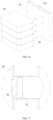
- FIG. 4 is a schematic structural diagram of an energy storage device according to an embodiment of this application
- FIG. 5 is a close-up view of a part B shown in FIG. 4
- FIG. 6 is a schematic structural diagram of an exhaust system 200 according to an embodiment of this application.
- the exhaust assembly includes at least one partition plate 33.
- Each of the partition plates 33 includes an inner cavity 331 configured to temporarily store fumes.
- Each inner cavity 331 communicates with the exterior of the box 10.
- Each exhaust port 21 communicates with the inner cavity 331 of at least one partition plate 33.
- Each guide assembly 40 is disposed between one of the exhaust ports 21 and the inner cavity 331 in communication with the exhaust port, and is configured to expel the fumes in the battery cabinet 20 out of the box 10 unidirectionally from the partition plate 33.
- the plurality of battery cabinets 20 are stacked in sequence to form a battery cabinet group, and then a plurality of battery cabinet groups are spaced apart horizontally inside the box 10. Further, a partition plate 33 is disposed in a gap between every two adjacent battery cabinet groups.
- An exhaust port 21 may be created on a side of each battery cabinet 20 in the battery cabinet group, the side being oriented toward the partition plate 33. The exhaust port 21 communicates with the inner cavity 331 of the partition plate 33.
- the guide assembly 40 is disposed between each exhaust port 21 and the inner cavity 331 in communication with the exhaust port.
- each partition plate 33 communicates with the exterior of the box 10. In this way, after the fumes in the battery cabinet 20 are expelled into the inner cavity 331 of the partition plate 33 through the exhaust port 21, the fumes are expelled out of the box 10 from the inner cavity 331.
- a through-hole (not shown in the drawing) connecting the inner cavity 331 of the partition plate 33 to the exterior of the box 10 may be created on the box 10 at a position corresponding to the partition plate 33.
- a control valve is disposed in the through-hole to control the opening/closing of the passage between the inner cavity 331 and the exterior of the box 10.
- other similar structures may be used to implement the communication between the inner cavity 331 and the exterior of the box 10, the details of which are omitted here.
- FIG. 7 is a schematic structural diagram of connection between an exhaust port and an exhaust assembly according to an embodiment of this application.
- each guide assembly 40 includes an exhaust valve 41.
- the exhaust valve 41 is configured to control the opening/closing of the passage between each exhaust port 21 and the exhaust assembly in communication with the exhaust port.
- the exhaust valve 41 is a one-way exhaust valve 41 so as to be able to implement unidirectional exhaustion of the fumes from inside the battery cabinet 20 into the corresponding exhaust assembly.
- the exhaust valve 41 may be an electrical control valve, and is communicatively connected to the BMS. In this way, when detecting that thermal runaway occurs inside a battery cabinet 20, the BMS sends a signal. Upon receiving the signal, the electrical control valve opens automatically to implement directional exhaustion of fumes of the battery cabinet 20.
- each guide assembly 40 further includes a connecting piece 42.
- the exhaust valve 41 is disposed in the connecting piece 42.
- One end of the connecting piece 42 along an extension direction of the connecting piece communicates with a corresponding exhaust port 21, and the other end of the connecting piece communicates with a corresponding exhaust assembly.
- the connecting piece 42 is a hollow cylindrical deflector hood.
- the exhaust valve 41 is fixedly disposed in the deflector hood.
- One end of the deflector hood communicates with a corresponding exhaust port 21, and the other end of the deflector hood communicates with a corresponding exhaust assembly.
- the deflector hood plays a role in hermetic connection, makes it more convenient to implement detachable connection between the exhaust assembly and the battery cabinet 20, and is conveniently operable.
- each guide assembly 40 includes a protection piece 43 hermetically disposed at a corresponding exhaust port 21.
- the protection piece 43 is able to be detached from the exhaust port 21 under an impact force of the fumes in a corresponding battery cabinet 20.
- the protection piece 43 forms a fragile configuration on the outside of the battery cabinet 20. When the battery cabinet 20 is operating normally, the protection piece 43 prevents external gas or fumes from entering the battery cabinet 20 from the exhaust port 21.
- the protection piece 43 can be detached from the exhaust port 21 under the impact force of the fumes, thereby implementing unidirectional exhaustion of the fumes from inside the battery cabinet 20 and diffusion of the fumes to the branch pipes 30.
- the protection piece 43 is made of an aluminum laminated film.
- the aluminum laminated film is hermetically bonded to the position of the exhaust port 21.
- the fumes in the battery cabinet 20 directly burst through the aluminum laminated film and are expelled out of the box 10 through the branch pipe 30.
- the aluminum laminated film plays a protective role for the exhaust port 21, and prevents external fumes from entering the battery cabinet 20 from the exhaust port 21.
- the fumes in the battery cabinet 20 can directly burst through the aluminum laminated film to implement directional exhaustion.
- the energy storage device includes a box 10, a battery cabinet 20 disposed in the box 10, a control module (not shown in the drawing), and the exhaust system 200 disclosed above.
- the exhaust system 200 implements communication between the battery cabinet 20 and the exterior of the box 10.
- the control module is communicatively connected to the exhaust system 200.
- control module is disposed to control the opening and closing of the exhaust valve 41 corresponding to each battery cabinet 20, thereby controlling the opening/closing of the passage between each battery cabinet 20 and the corresponding exhaust assembly. In this way, the exhaustion of the fumes of the battery cabinet 20 can be controlled automatically.
- control module may be a BMS
- the exhaust valve 41 is an electrical control valve.
- the BMS sends a signal and locks the position of the battery cabinet 20.
- the electrical control valve opens automatically to implement directional exhaustion of fumes of the battery cabinet 20.
- this application provides an electrical device including an electrical main body and the energy storage device 100 disclosed above.
- each branch pipe 31 is connected to a corresponding battery cabinet 20. All the branch pipes converge into the main pipe 32 communicating to the outside of the box 10.
- each battery cabinet 20 communicates with the inner cavity 331 of a partition plate 33 through an exhaust valve 41, and communicates to the outside of the box 10 through a through-hole on the box 10.
- the BMS locks the position of the battery cabinet 20 and transmits a signal to the electrical control valve.
- the electrical control valve opens automatically to implement directional exhaustion of fumes of the battery cabinet 20. In this way, the fumes in the battery cabinet 20 are expelled, thereby preventing the battery cabinet 20 from exploding due to insufficient strength.
- the exhaust channel of each battery cabinet 20 is independent. Therefore, the exhaustion of fumes is prevented from affecting other normally operating battery cabinets 20 in the box 10, thereby improving the safety performance of the overall structure of the energy storage device 100.
- the exhaust system 200 for an energy storage device 100, the energy storage device 100, and the electrical device in the foregoing embodiments exhibit at least the following advantages:
Landscapes
- Chemical & Material Sciences (AREA)
- Chemical Kinetics & Catalysis (AREA)
- Electrochemistry (AREA)
- General Chemical & Material Sciences (AREA)
- Battery Mounting, Suspending (AREA)
- Gas Exhaust Devices For Batteries (AREA)
Abstract
Description
- This application claims priority to
Chinese Patent Application No. 202220381226.0, filed on February 24, 2022 - This application relates to the technical field of energy storage batteries, in particular, to an exhaust system for an energy storage device, an energy storage device, and an electrical device.
- With the vigorous development of renewable energy, an energy storage device is required to alleviate the pressure of a power grid in smoothing out peak loads and regulating frequencies. Among various energy storage methods, electrochemical energy storage is one of the most rapidly developing energy storage methods. Due to the large amount of organic electrolyte solution inside a battery, a battery energy storage device in use is prone to incur some safety hazards. When the temperature uniformity between batteries is low or when a battery is overcharged or overdischarged, thermal runaway may occur inside the battery. The thermal runaway of the battery is accompanied by a large amount of high-temperature flammable fumes that may lead to battery explosions or other secondary hazards, thereby impairing the safety performance of the energy storage device.
- In view of the situation above, it is necessary to provide an exhaust system for an energy storage device, an energy storage device, and an electrical device to exhaust the fumes in the energy storage device.
- According to a first aspect, this application provides an exhaust system for an energy storage device. The energy storage device includes a box and at least two battery cabinets disposed in the box. An exhaust port is created on each battery cabinet.
- The exhaust system includes: an exhaust assembly, communicating with each of the exhaust ports sequentially, and configured to collect fumes expelled from the exhaust ports; and at least two guide assemblies, where each guide assembly is disposed between one of the exhaust ports and the exhaust assembly in communication with the exhaust port, and is configured to expel the fumes in the battery cabinet out of the box unidirectionally from the exhaust assembly through the exhaust port.
- In the technical solution of an embodiment of this application, by controlling the guide assembly disposed between the battery cabinet and the exhaust assembly connected to the battery cabinet, the opening/closing of the passage is controlled between the exhaust port on the battery cabinet and the exhaust assembly in communication with the exhaust port. In this way, high-temperature flammable fumes inside the battery cabinet can be expelled unidirectionally out of the box from the exhaust assembly through the exhaust port. When the fumes in the battery cabinet are expelled, an independent exhaust channel is formed between an individual battery cabinet and the outside of the box at the same time, so that the exhaustion of the fumes does not affect other normally operating battery cabinets in the box.
- In some embodiments, the exhaust assembly includes at least two branch pipes. One end of each branch pipe communicates with one of the exhaust ports, and another end of the branch pipe extends out of the box.
- Each guide assembly is disposed between one of the exhaust ports and the branch pipe in communication with the exhaust port, and is configured to expel the fumes in the battery cabinet out of the box unidirectionally from the branch pipe.
- In the technical solution of this embodiment of this application, the exhaust assembly employs pipes. Each pipe corresponds to an exhaust port. In this way, the fumes in each battery cabinet are expelled separately through a corresponding pipe. The battery cabinets expel fumes without mutual interference, and are highly independent.
- In some embodiments, the exhaust assembly includes a main pipe. All the branch pipes communicate with the main pipe and extend out of the box through the main pipe.
- In the technical solution of this embodiment of this application, a main-branch pipeline layout is implemented, so that each battery cabinet can be fitted with a branch pipe separately, and the operation is simple. In addition, all the branch pipes converge into the main pipe, and the fumes are expelled out of the box in a unified manner, thereby making the pipe structure in the box clearer and more reasonable.
- In some embodiments, the exhaust assembly includes at least one partition plate. Each of the partition plates includes an inner cavity configured to temporarily store fumes. Each inner cavity communicates with an exterior of the box.
- Each exhaust port communicates with the inner cavity of at least one partition plate. Each guide assembly is disposed between one of the exhaust ports and the inner cavity in communication with the exhaust port, and is configured to expel the fumes in the battery cabinet out of the box unidirectionally from the partition plate.
- In the technical solution of this embodiment of this application, each partition plate can correspond to a plurality of battery cabinets for expelling fumes. The fumes at each exhaust port are expelled unidirectionally by the guide assembly in one-to-one correspondence. In this way, the arrangement of the partition plate further simplifies the internal structure of the box on the basis of implementing unidirectional exhaustion of the fumes in the battery cabinet.
- In some embodiments, each guide assembly includes an exhaust valve. The exhaust valve is configured to control the opening/closing of the passage between each exhaust port and the exhaust assembly in communication with the exhaust port.
- In the technical solution of this embodiment of this application, by controlling the exhaust valve, the opening/closing of the passage is controlled between each exhaust port and the exhaust assembly in communication with the exhaust port, thereby implementing independent exhaustion of fumes for each individual battery cabinet.
- In some embodiments, each guide assembly further includes a connecting piece. The exhaust valve is disposed in the connecting piece. One end of the connecting piece along an extension direction of the connecting piece communicates with a corresponding exhaust port, and another end of the connecting piece communicates with a corresponding exhaust assembly.
- In the technical solution of this embodiment of this application, the connecting piece plays a role in hermetic connection, makes it more convenient to implement detachable connection between the exhaust assembly and the battery cabinet, and is conveniently operable.
- In some embodiments, each guide assembly includes a protection piece hermetically disposed at a corresponding exhaust port. The protection piece is able to be detached from the exhaust port under an impact force of the fumes in a corresponding battery cabinet.
- In the technical solution of this embodiment of this application, the protection piece forms a fragile configuration on the outside of the battery cabinet. When the battery cabinet is operating normally, the protection piece prevents external gas or fumes from entering the battery cabinet from the exhaust port. When fumes are generated inside the battery cabinet, the protection piece can be detached from the exhaust port under the impact force of the fumes, thereby implementing unidirectional exhaustion of the fumes from inside the battery cabinet and diffusion of the fumes to the branch pipes.
- In some embodiments, the protection piece is made of an aluminum laminated film.
- In the technical solution of this embodiment of this application, on the one hand, the aluminum laminated film plays a protective role for the exhaust port, and prevents external fumes from entering the battery cabinet from the exhaust port. On the other hand, the fumes in the battery cabinet can directly burst through the aluminum laminated film to implement directional exhaustion.
- According to a second aspect, this application provides an energy storage device. The energy storage device includes a box, an battery cabinet disposed in the box, a control module, and the exhaust system disclosed above. The exhaust system implements communication between the battery cabinet and the exterior of the box. The control module is communicatively connected to the exhaust system.
- According to a third aspect, this application provides an electrical device, including an electrical main body and the energy storage device disclosed above.
- In the exhaust system for an energy storage device, the energy storage device, and the electrical device, when thermal runaway occurs inside a battery cabinet of the energy storage device, high-temperature fumes can be expelled directionally into a corresponding exhaust assembly through an exhaust port under the action of a guide assembly, and then expelled out of the box through the exhaust assembly, thereby implementing directional exhaustion of the high-temperature fumes in the battery cabinet, avoiding explosion of the battery cabinet or secondary hazards, and improving safety performance of the energy storage device.
- The foregoing description is merely an overview of the technical solutions of this application. Some specific embodiments of this application are described below illustratively to enable a clearer understanding of the technical solutions of this application, enable implementation of the technical solutions based on the subject-matter hereof, and make the foregoing and other objectives, features, and advantages of this application more evident and comprehensible.
- By reading the following detailed description of embodiments, a person of ordinary skill in the art becomes clearly aware of various other advantages and benefits. The drawings are merely intended to illustrate the embodiments, but not to limit this application. In all the drawings, the same reference numeral represents the same component. In the drawings:
-
FIG. 1 is a schematic structural diagram of an energy storage device according to an embodiment of this application; -
FIG. 2 is a schematic structural diagram of an energy storage device according to an embodiment of this application; -
FIG. 3 is a schematic structural diagram of an exhaust system according to an embodiment of this application; -
FIG. 4 is a schematic structural diagram of an energy storage device according to another embodiment of this application; -
FIG. 5 is a close-up view of a position A shown inFIG. 4 ; -
FIG. 6 is a schematic structural diagram of an exhaust system according to another embodiment of this application; -
FIG. 7 is a schematic structural diagram of connection between a battery cabinet and an exhaust assembly according to an embodiment of this application; -
FIG. 8 is a schematic structural diagram of a battery cabinet according to an embodiment of this application; and -
FIG. 9 is a close-up view of a part B shown inFIG. 8 . - List of reference numerals: 100. energy storage device; 200. exhaust system; 10. box; 20. battery cabinet; 40. guide assembly; 50. main pipe; 21. exhaust port; 31. branch pipe; 32. main pipe; 33. partition plate; 41. exhaust valve; 42. connecting piece; 43. protection piece; 331. inner cavity.
- Some embodiments of the technical solutions of this application are described in detail below with reference to the drawings. The following embodiments are merely intended as examples to describe the technical solutions of this application more clearly, but not intended to limit the protection scope of this application.
- Unless otherwise defined, all technical and scientific terms used herein bear the same meanings as what is normally understood by a person skilled in the technical field of this application. The terms used herein are merely intended to describe specific embodiments but not to limit this application. The terms "include" and "contain" and any variations thereof used in the specification, claims, and brief description of drawings of this application are intended as non-exclusive inclusion.
- In the description of some embodiments of this application, the technical terms "first" and "second" are merely intended to distinguish between different items but not intended to indicate or imply relative importance or implicitly specify the number of the indicated technical features, specific order, or order of precedence. In the description of some embodiments of this application, unless otherwise expressly specified, "a plurality of" means two or more.
- Reference to an "embodiment" herein means that a specific feature, structure or characteristic described with reference to this embodiment may be included in at least one embodiment of this application. Reference to this term in different places in the specification does not necessarily represent the same embodiment, nor does it represent an independent or alternative embodiment in a mutually exclusive relationship with other embodiments. A person skilled in the art explicitly and implicitly understands that the embodiments described herein may be combined with other embodiments.
- In the description of embodiments of this application, the term "and/or" merely indicates a relationship between related items, and represents three possible relationships. For example, "A and/or B" may represent the following three circumstances: A alone, both A and B, and B alone. In addition, the character "/" herein generally indicates an "or" relationship between the item preceding the character and the item following the character.
- In the description of embodiments of this application, the term "a plurality of" means two or more (including two). Similarly, "a plurality of groups" means two or more groups (including two groups), and "a plurality of pieces" means two or more pieces (including two pieces).
- In the description of embodiments of this application, a direction or a positional relationship indicated by the terms such as "center", "longitudinal", "transverse", "length", "width", "thickness", "up", "down", "before", "after", "left", "right", "vertical", "horizontal", "top", "bottom", "in", "out", "clockwise", "counterclockwise", "axial", "radial", and "circumferential" is a direction or positional relationship based on the illustration in the drawings, and is merely intended for ease or brevity of description of embodiments of this application, but not intended to indicate or imply that the indicated device or component is necessarily located in the specified direction or constructed or operated in the specified direction. Therefore, such terms are not to be understood as a limitation on embodiments of this application.
- In the description of this application, unless otherwise expressly specified and defined, the technical terms such as "mount", "concatenate", "connect", and "fix" are generic in a broad sense, for example, mean a fixed connection, a detachable connection, or a one-piece configuration; or mean a mechanical connection or an electrical connection; or mean a direct connection or an indirect connection implemented through an intermediary; or mean internal communication between two components or interaction between two components. A person of ordinary skill in the art can understand the specific meanings of the terms in some embodiments of this application according to specific situations.
- An energy storage device is mainly intended for supplying power to large-scale electrical equipment, and a majority of energy storage devices do not need to move. Therefore, for an energy storage battery in an energy storage device, just the power density needs to be adjusted depending on the energy storage scenario, but typically no direct requirement is imposed on the energy density. For energy storage scenarios of power grid peak shaving, off-grid photovoltaic energy storage, or user-side electricity price difference between peak and valley periods, the energy storage battery is usually charged or discharged continuously for at least two hours. Therefore, a capacity-type battery with a charge-discharge rate less than or equal to 0.5 C is applicable to such scenarios. For energy storage scenarios of power frequency regulation or smoothing fluctuations in renewable energy, the energy storage battery needs to be charged and discharged quickly in a period as short as seconds or minutes, and therefore, a power-type battery is applicable to with a charge-discharge rate greater than or equal to 2 C is applicable to such scenarios.
- The applicant has noticed that the energy storage device generates a large amount of heat during use, giving rise to an increase in safety hazards. When the temperature uniformity between a plurality of batteries is low or when a battery is overcharged or overdischarged, thermal runaway inside the battery may result in local smoke or even fire. An existing energy storage device does not provide a corresponding directional exhaust system. Therefore, the high-temperature flammable fumes caused by thermal runaway of the battery are unable to be expelled directionally. Therefore, the high-temperature flammable fumes are either retained inside the battery box, or expelled into the energy storage device through an explosion-proof valve of the battery box. When the high-temperature flammable fumes are retained inside the battery box, the strength of the battery box is limited, and an explosion of the battery box is prone to occur. When the high-temperature flammable fumes are expelled directly into the energy storage device, the high-temperature flammable fumes may impact the surrounding normally operating battery boxes, and give rise to occurrence of secondary hazards.
- To implement directional exhaustion of high-temperature flammable fumes in the battery box, the applicant hereof has found that a special-purpose exhaust assembly may be designed for each battery box inside the energy storage device. Through a corresponding guide assembly disposed, the high-temperature flammable fumes in the battery box can be expelled directionally into a corresponding exhaust assembly, and then expelled out of the energy storage device through the exhaust assembly.
- In this way, when high-temperature flammable fumes are generated by one or more battery boxes due to thermal runaway, the fumes can be expelled out of the energy storage device through the exhaust assembly that is correspondingly connected to the battery box. The fumes are prevented from accumulating inside the battery box and giving rise to an explosion of the battery box, and the fumes are prevented from diffusing into the energy storage device from the battery box and giving rise to secondary hazards, thereby improving safety performance of the energy storage device.
- Referring to
FIG. 1, FIG. 2 , andFIG. 3 ,FIG. 1 and FIG. 2 are schematic structural diagrams of an energy storage device according to an embodiment of this application, andFIG. 3 is a schematic structural diagram of an exhaust system according to an embodiment of this application. An embodiment of this application provides anexhaust system 200 for anenergy storage device 100. Theenergy storage device 100 includes abox 10 and at least twobattery cabinets 20 disposed in thebox 10. Anexhaust port 21 is created on eachbattery cabinet 20. Theexhaust system 200 includes an exhaust assembly and at least twoguide assemblies 40. The exhaust assembly communicates with each of theexhaust ports 21 sequentially, and is configured to collect fumes expelled from theexhaust ports 21. Eachguide assembly 40 is disposed between one of theexhaust ports 21 and the exhaust assembly in communication with the exhaust port, and is configured to expel the fumes in thebattery cabinet 20 out of thebox 10 unidirectionally from the exhaust assembly through theexhaust port 21. - Specifically, the
box 10 of theenergy storage device 100 may assume a container structure. All thebattery cabinets 20 are arranged and accommodated inside the container structure to form an integral structure, thereby facilitating supply of power to external electrical devices. Thebattery cabinets 20 located inside the container structure are a main structure for implementing the supply of power. Therefore, the specific number ofbattery cabinets 20 may be set based on the power of the electrical devices. - An
exhaust port 21 is created on eachbattery cabinet 20. The exhaust assembly is one-to-one connected to theexhaust port 21 on eachbattery cabinet 20. Eachguide assembly 40 is one-to-one disposed between theexhaust port 21 and the exhaust assembly. By controlling theguide assembly 40 disposed between thebattery cabinet 20 and the exhaust assembly connected to the battery cabinet, the opening/closing of the passage is controlled between theexhaust port 21 on thebattery cabinet 20 and the exhaust assembly in communication with the exhaust port. - When high-temperature flammable fumes are generated by thermal runaway inside a
battery cabinet 20, theexhaust port 21 on thebattery cabinet 20 and the exhaust assembly connected to the exhaust port are opened so that the high-temperature flammable fumes inside thebattery cabinet 20 can be expelled unidirectionally out of thebox 10 from the exhaust assembly through theexhaust port 21. Therefore, when the fumes in thebattery cabinet 20 are expelled, an independent exhaust channel is formed between anindividual battery cabinet 20 and the outside of thebox 10 at the same time, so that the exhaustion of the fumes does not affect other normally operatingbattery cabinets 20 in thebox 10. - It is hereby noted that the
guide assembly 40 may be controlled manually or may be controlled automatically through connection to an external control module. When theguide assembly 40 is controlled automatically, the fume indicator of eachbattery cabinet 20 may be detected by the control module. When the fume indicator of abattery cabinet 20 is detected as abnormal, the control module controls theguide assembly 40 corresponding to thebattery cabinet 20, and controls the opening/closing of the exhaust assembly corresponding to thatbattery cabinet 20, thereby implementing exhaustion of the fumes of the specifiedbattery cabinet 20. - Specifically, in an embodiment, the control module may use a battery management system (BMS). When detecting that thermal runaway occurs inside a
battery cabinet 20, the BMS sends a signal. Upon receiving the signal, theguide assembly 40 opens automatically to implement directional exhaustion of fumes of thebattery cabinet 20. - It is hereby noted that the battery management system (BMS for short) is primarily configured to perform intelligent management and maintenance for the battery.
- In some embodiments, the exhaust assembly includes at least two
branch pipes 31. One end of eachbranch pipe 31 communicates with one of theexhaust ports 21, and another end of the branch pipe extends out of thebox 10. Eachguide assembly 40 is disposed between one of theexhaust ports 21 and thebranch pipe 31 in communication with the exhaust port, and is configured to expel the fumes in thebattery cabinet 20 out of thebox 10 unidirectionally from thebranch pipe 31. - Specifically, the number of
branch pipes 31 corresponds to the number ofexhaust ports 21 on thebattery cabinet 20. Onebranch pipe 31 corresponds to oneexhaust port 21. In other words, eachexhaust port 21 and abranch pipe 31 connected to the exhaust port together form an independent exhaust channel. In this way, the fumes of eachbattery cabinet 20 can be exhausted independently. Eachguide assembly 40 controls the opening/closing of one exhaust channel, so that the fumes of eachbattery cabinet 20 can be exhausted independently, thereby implementing a safer process of exhausting the fumes of thebattery cabinet 20. - In some embodiments, the exhaust assembly includes a
main pipe 32. All thebranch pipes 31 communicate with themain pipe 32 and extend out of thebox 10 through themain pipe 32. One end of eachbranch pipe 31 is connected to acorresponding battery cabinet 20, and the other end of each branch pipe is connected to themain pipe 32, thereby implementing a main-branch pipeline layout. Eachbattery cabinet 20 can be fitted with abranch pipe 31 separately, and the operation is simple. In addition, all thebranch pipes 31 converge into themain pipe 32, and the fumes are uniformly expelled out of thebox 10, thereby making the pipe structure in thebox 10 clearer and more reasonable. - Referring to
FIG. 4 ,FIG. 5 , andFIG. 6 ,FIG. 4 is a schematic structural diagram of an energy storage device according to an embodiment of this application,FIG. 5 is a close-up view of a part B shown inFIG. 4 , andFIG. 6 is a schematic structural diagram of anexhaust system 200 according to an embodiment of this application. In some embodiments, the exhaust assembly includes at least onepartition plate 33. Each of thepartition plates 33 includes aninner cavity 331 configured to temporarily store fumes. Eachinner cavity 331 communicates with the exterior of thebox 10. Eachexhaust port 21 communicates with theinner cavity 331 of at least onepartition plate 33. Eachguide assembly 40 is disposed between one of theexhaust ports 21 and theinner cavity 331 in communication with the exhaust port, and is configured to expel the fumes in thebattery cabinet 20 out of thebox 10 unidirectionally from thepartition plate 33. - Specifically, in order to improve the space utilization rate inside the
box 10, the plurality ofbattery cabinets 20 are stacked in sequence to form a battery cabinet group, and then a plurality of battery cabinet groups are spaced apart horizontally inside thebox 10. Further, apartition plate 33 is disposed in a gap between every two adjacent battery cabinet groups. Anexhaust port 21 may be created on a side of eachbattery cabinet 20 in the battery cabinet group, the side being oriented toward thepartition plate 33. Theexhaust port 21 communicates with theinner cavity 331 of thepartition plate 33. Theguide assembly 40 is disposed between eachexhaust port 21 and theinner cavity 331 in communication with the exhaust port. - In addition, the
inner cavity 331 of eachpartition plate 33 communicates with the exterior of thebox 10. In this way, after the fumes in thebattery cabinet 20 are expelled into theinner cavity 331 of thepartition plate 33 through theexhaust port 21, the fumes are expelled out of thebox 10 from theinner cavity 331. In a specific embodiment, a through-hole (not shown in the drawing) connecting theinner cavity 331 of thepartition plate 33 to the exterior of thebox 10 may be created on thebox 10 at a position corresponding to thepartition plate 33. A control valve is disposed in the through-hole to control the opening/closing of the passage between theinner cavity 331 and the exterior of thebox 10. Alternatively, in some other embodiments, other similar structures may be used to implement the communication between theinner cavity 331 and the exterior of thebox 10, the details of which are omitted here. - Referring to
FIG. 7, FIG. 7 is a schematic structural diagram of connection between an exhaust port and an exhaust assembly according to an embodiment of this application. In some embodiments, eachguide assembly 40 includes anexhaust valve 41. Theexhaust valve 41 is configured to control the opening/closing of the passage between eachexhaust port 21 and the exhaust assembly in communication with the exhaust port. Specifically in this embodiment, theexhaust valve 41 is a one-way exhaust valve 41 so as to be able to implement unidirectional exhaustion of the fumes from inside thebattery cabinet 20 into the corresponding exhaust assembly. - More specifically, the
exhaust valve 41 may be an electrical control valve, and is communicatively connected to the BMS. In this way, when detecting that thermal runaway occurs inside abattery cabinet 20, the BMS sends a signal. Upon receiving the signal, the electrical control valve opens automatically to implement directional exhaustion of fumes of thebattery cabinet 20. - In some embodiments, each
guide assembly 40 further includes a connectingpiece 42. Theexhaust valve 41 is disposed in the connectingpiece 42. One end of the connectingpiece 42 along an extension direction of the connecting piece communicates with acorresponding exhaust port 21, and the other end of the connecting piece communicates with a corresponding exhaust assembly. Specifically in this embodiment, the connectingpiece 42 is a hollow cylindrical deflector hood. Theexhaust valve 41 is fixedly disposed in the deflector hood. One end of the deflector hood communicates with acorresponding exhaust port 21, and the other end of the deflector hood communicates with a corresponding exhaust assembly. The deflector hood plays a role in hermetic connection, makes it more convenient to implement detachable connection between the exhaust assembly and thebattery cabinet 20, and is conveniently operable. - Referring to
FIG. 8 and FIG. 9, FIG. 8 is a schematic structural diagram of a battery cabinet according to an embodiment of this application, andFIG. 9 is a close-up view of a part B shown inFIG. 8 . In some embodiments, eachguide assembly 40 includes aprotection piece 43 hermetically disposed at acorresponding exhaust port 21. Theprotection piece 43 is able to be detached from theexhaust port 21 under an impact force of the fumes in acorresponding battery cabinet 20. Theprotection piece 43 forms a fragile configuration on the outside of thebattery cabinet 20. When thebattery cabinet 20 is operating normally, theprotection piece 43 prevents external gas or fumes from entering thebattery cabinet 20 from theexhaust port 21. When fumes are generated inside thebattery cabinet 20, theprotection piece 43 can be detached from theexhaust port 21 under the impact force of the fumes, thereby implementing unidirectional exhaustion of the fumes from inside thebattery cabinet 20 and diffusion of the fumes to the branch pipes 30. - Specifically, the
protection piece 43 is made of an aluminum laminated film. The aluminum laminated film is hermetically bonded to the position of theexhaust port 21. When thermal runaway occurs inside thebattery cabinet 20, the fumes in thebattery cabinet 20 directly burst through the aluminum laminated film and are expelled out of thebox 10 through the branch pipe 30. On the one hand, the aluminum laminated film plays a protective role for theexhaust port 21, and prevents external fumes from entering thebattery cabinet 20 from theexhaust port 21. On the other hand, the fumes in thebattery cabinet 20 can directly burst through the aluminum laminated film to implement directional exhaustion. - Based on the same conception as the
exhaust system 200 above, this application provides anenergy storage device 100. The energy storage device includes abox 10, abattery cabinet 20 disposed in thebox 10, a control module (not shown in the drawing), and theexhaust system 200 disclosed above. Theexhaust system 200 implements communication between thebattery cabinet 20 and the exterior of thebox 10. The control module is communicatively connected to theexhaust system 200. - To facilitate the control of the exhaustion of the fumes, the control module is disposed to control the opening and closing of the
exhaust valve 41 corresponding to eachbattery cabinet 20, thereby controlling the opening/closing of the passage between eachbattery cabinet 20 and the corresponding exhaust assembly. In this way, the exhaustion of the fumes of thebattery cabinet 20 can be controlled automatically. - Specifically, the control module may be a BMS, and the
exhaust valve 41 is an electrical control valve. When detecting that thermal runaway occurs inside abattery cabinet 20, the BMS sends a signal and locks the position of thebattery cabinet 20. Upon receiving the signal, the electrical control valve opens automatically to implement directional exhaustion of fumes of thebattery cabinet 20. - Based on the same conception as the
energy storage device 100, this application provides an electrical device including an electrical main body and theenergy storage device 100 disclosed above. - In specific use of this application, each
branch pipe 31 is connected to acorresponding battery cabinet 20. All the branch pipes converge into themain pipe 32 communicating to the outside of thebox 10. Alternatively, eachbattery cabinet 20 communicates with theinner cavity 331 of apartition plate 33 through anexhaust valve 41, and communicates to the outside of thebox 10 through a through-hole on thebox 10. - When thermal runaway occurs in a
battery cabinet 20, the BMS locks the position of thebattery cabinet 20 and transmits a signal to the electrical control valve. Upon receiving the signal, the electrical control valve opens automatically to implement directional exhaustion of fumes of thebattery cabinet 20. In this way, the fumes in thebattery cabinet 20 are expelled, thereby preventing thebattery cabinet 20 from exploding due to insufficient strength. In addition, the exhaust channel of eachbattery cabinet 20 is independent. Therefore, the exhaustion of fumes is prevented from affecting other normally operatingbattery cabinets 20 in thebox 10, thereby improving the safety performance of the overall structure of theenergy storage device 100. - The
exhaust system 200 for anenergy storage device 100, theenergy storage device 100, and the electrical device in the foregoing embodiments exhibit at least the following advantages: - (1) The
guide assembly 40 implements directional exhaustion of the fumes from inside thebattery cabinet 20 to the outside of thebox 10, ensures stability of the pressure inside thebattery cabinet 20, and avoids explosion caused by failure to expel the fumes in thebattery cabinet 20; - (2) Each
branch pipe 31 is disposed corresponding to onebattery cabinet 20, so that the fumes inside eachbattery cabinet 20 can be expelled out of thebox 10 independently without affecting normal operation ofother battery cabinets 20 in thebox 10, thereby improving the overall safety performance of theenergy storage device 100; and - (3) A main-branch pipeline layout is implemented, in which the
branch pipes 31 are connected to themain pipe 32, so that eachbattery cabinet 20 can be fitted with abranch pipe 31 separately, thereby simplifying and facilitating the operation. - Finally, it is hereby noted that the foregoing embodiments are merely intended to describe the technical solutions of this application but not to limit this application. Although this application has been described in detail with reference to the foregoing embodiments, a person of ordinary skill in the art understands that modifications may still be made to the technical solutions described in the foregoing embodiments, or equivalent replacements may still be made to some or all technical features in the technical solutions. Such modifications and equivalent replacements fall within the scope of the claims and specification hereof without making the essence of the corresponding technical solutions depart from the scope of the technical solutions of the embodiments of this application. Particularly, to the extent that no structural conflict exists, various technical features mentioned in different embodiments may be combined in any manner. This application is not limited to the specific embodiments disclosed herein, but includes all technical solutions falling within the scope of the claims.
Claims (10)
- An exhaust system for an energy storage device, wherein the energy storage device comprises a box and at least two battery cabinets disposed in the box, and an exhaust port is created on each battery cabinet, and the exhaust system comprises:an exhaust assembly, communicating with each of the exhaust ports sequentially, and configured to collect fumes expelled from the exhaust ports; andat least two guide assemblies, wherein each guide assembly is disposed between one of the exhaust ports and the exhaust assembly in communication with the exhaust port, and is configured to expel the fumes in the battery cabinet out of the box unidirectionally from the exhaust assembly through the exhaust port.
- The exhaust system according to claim 1, wherein the exhaust assembly comprises at least two branch pipes, one end of each branch pipe communicates with one of the exhaust ports, and another end of the branch pipe extends out of the box; and
each guide assembly is disposed between one of the exhaust ports and the branch pipe in communication with the exhaust port, and is configured to expel the fumes in the battery cabinet out of the box unidirectionally from the branch pipe. - The exhaust system according to claim 2, wherein the exhaust assembly comprises a main pipe, and all the branch pipes communicate with the main pipe and extend out of the box through the main pipe.
- The exhaust system according to any one of claims 1 to 3, wherein the exhaust assembly comprises at least one partition plate, each of the partition plates comprises an inner cavity configured to temporarily store fumes, and each inner cavity communicates with an exterior of the box; and
each exhaust port communicates with the inner cavity of at least one partition plate, and each guide assembly is disposed between one of the exhaust ports and the inner cavity in communication with the exhaust port, and is configured to expel the fumes in the battery cabinet out of the box unidirectionally from the partition plate. - The exhaust system according to any one of claims 1 to 4, wherein each guide assembly comprises an exhaust valve, and the exhaust valve is configured to control opening/closing of a passage between each exhaust port and the exhaust assembly in communication with the exhaust port.
- The exhaust system according to claim 5, wherein each guide assembly further comprises a connecting piece, the exhaust valve is disposed in the connecting piece, one end of the connecting piece along an extension direction of the connecting piece communicates with a corresponding exhaust port, and another end of the connecting piece communicates with a corresponding exhaust assembly.
- The exhaust system according to any one of claims 1 to 6, wherein each guide assembly comprises a protection piece hermetically disposed at a corresponding exhaust port, and the protection piece is able to be detached from the exhaust port under an impact force of the fumes in a corresponding battery cabinet.
- The exhaust system according to claim 7, wherein the protection piece is made of an aluminum laminated film.
- An energy storage device, comprising a box, an battery cabinet disposed in the box, a control module, and the exhaust system according to any one of claims 1 to 8, wherein the exhaust system implements communication between the battery cabinet and an exterior of the box, and the control module is communicatively connected to the exhaust system.
- An electrical device, comprising an electrical main body and the energy storage device according to claim 9.
Applications Claiming Priority (2)
| Application Number | Priority Date | Filing Date | Title |
|---|---|---|---|
| CN202220381226.0U CN217182360U (en) | 2022-02-24 | 2022-02-24 | Smoke exhaust system for energy storage device, energy storage device and power utilization device |
| PCT/CN2023/075093 WO2023160396A1 (en) | 2022-02-24 | 2023-02-09 | Smoke exhaust system for energy storage device, energy storage device, and electrical device |
Publications (2)
| Publication Number | Publication Date |
|---|---|
| EP4407773A1 true EP4407773A1 (en) | 2024-07-31 |
| EP4407773A4 EP4407773A4 (en) | 2025-03-12 |
Family
ID=82739411
Family Applications (1)
| Application Number | Title | Priority Date | Filing Date |
|---|---|---|---|
| EP23759021.1A Pending EP4407773A4 (en) | 2022-02-24 | 2023-02-09 | Smoke exhaust system for energy storage device, energy storage device, and electrical device |
Country Status (4)
| Country | Link |
|---|---|
| US (1) | US20240258641A1 (en) |
| EP (1) | EP4407773A4 (en) |
| CN (1) | CN217182360U (en) |
| WO (1) | WO2023160396A1 (en) |
Families Citing this family (7)
| Publication number | Priority date | Publication date | Assignee | Title |
|---|---|---|---|---|
| CN217182360U (en) * | 2022-02-24 | 2022-08-12 | 宁德时代新能源科技股份有限公司 | Smoke exhaust system for energy storage device, energy storage device and power utilization device |
| WO2024065210A1 (en) * | 2022-09-27 | 2024-04-04 | 宁德时代新能源科技股份有限公司 | Energy storage device |
| CN222673181U (en) * | 2023-12-08 | 2025-03-25 | 华为数字能源技术有限公司 | Directional energy storage cabinet and energy storage system that discharges fume |
| WO2024149055A1 (en) * | 2023-01-10 | 2024-07-18 | 华为数字能源技术有限公司 | Energy storage system and electric apparatus |
| CN222514996U (en) * | 2023-12-15 | 2025-02-21 | 华为数字能源技术有限公司 | Energy storage container and energy storage system with directional smoke exhaust |
| EP4579916A1 (en) * | 2023-12-27 | 2025-07-02 | Eve Energy Storage Co., Ltd. | Energy storage device and energy storage system |
| CN118983552A (en) * | 2024-07-05 | 2024-11-19 | 华为数字能源技术有限公司 | Energy storage cabinet and fire-fighting method thereof |
Family Cites Families (10)
| Publication number | Priority date | Publication date | Assignee | Title |
|---|---|---|---|---|
| JP4935802B2 (en) * | 2008-12-10 | 2012-05-23 | パナソニック株式会社 | Battery module and assembled battery module using the same |
| JP5466906B2 (en) * | 2009-09-18 | 2014-04-09 | パナソニック株式会社 | Battery module |
| JP2018077932A (en) * | 2015-03-18 | 2018-05-17 | 三洋電機株式会社 | Power supply device |
| CN111668410B (en) * | 2019-03-08 | 2021-12-07 | 比亚迪股份有限公司 | Power battery package and vehicle |
| CN110459719B (en) * | 2019-08-29 | 2024-11-12 | 清华大学 | Battery pack flue gas flow duct system and battery pack |
| EP4050630B1 (en) * | 2019-10-23 | 2025-10-01 | GS Yuasa International Ltd. | Electrical storage device |
| DE102020111453A1 (en) * | 2020-04-27 | 2021-10-28 | Audi Aktiengesellschaft | Energy storage cell |
| CN215451687U (en) * | 2021-04-16 | 2022-01-07 | 欣旺达电动汽车电池有限公司 | Heat dissipation system |
| CN113725552A (en) * | 2021-08-20 | 2021-11-30 | 陕西奥林波斯电力能源有限责任公司 | Battery with let out and explode device and have battery module who lets out and explode device |
| CN217182360U (en) * | 2022-02-24 | 2022-08-12 | 宁德时代新能源科技股份有限公司 | Smoke exhaust system for energy storage device, energy storage device and power utilization device |
-
2022
- 2022-02-24 CN CN202220381226.0U patent/CN217182360U/en active Active
-
2023
- 2023-02-09 EP EP23759021.1A patent/EP4407773A4/en active Pending
- 2023-02-09 WO PCT/CN2023/075093 patent/WO2023160396A1/en not_active Ceased
-
2024
- 2024-04-10 US US18/631,502 patent/US20240258641A1/en active Pending
Also Published As
| Publication number | Publication date |
|---|---|
| EP4407773A4 (en) | 2025-03-12 |
| US20240258641A1 (en) | 2024-08-01 |
| CN217182360U (en) | 2022-08-12 |
| WO2023160396A1 (en) | 2023-08-31 |
Similar Documents
| Publication | Publication Date | Title |
|---|---|---|
| EP4407773A1 (en) | Smoke exhaust system for energy storage device, energy storage device, and electrical device | |
| US11302972B2 (en) | Battery pack including batteries | |
| CN110199406B (en) | Battery system | |
| EP4593178A1 (en) | Energy storage device | |
| EP3806177A1 (en) | Cover assembly of secondary battery and secondary battery | |
| US20250279531A1 (en) | Battery and energy storage apparatus | |
| EP4254631A1 (en) | Energy storage prefabricated compartment and energy storage system | |
| US20250007091A1 (en) | Battery, electric apparatus, and method and device for preparing battery | |
| WO2023077848A1 (en) | Directional exhaust device, battery, and energy storage prefabricated compartment | |
| WO2026081569A1 (en) | Energy storage device, energy storage system, and charging network | |
| WO2025011391A1 (en) | Battery and electric device | |
| CN216213693U (en) | Lithium battery explosion-proof equipment of monitoring and cooling | |
| EP4358261A1 (en) | Directional exhaust device, battery, and energy storage prefabricated bin | |
| CN111682142A (en) | A battery pack with fire extinguishing function and control method thereof | |
| CN214099693U (en) | Lithium battery capable of realizing multi-module cascade based on direct current contactor control | |
| CN224096830U (en) | A battery box and an energy storage system thereon | |
| CN213278262U (en) | Automatic battery module, battery package of putting out a fire | |
| CN117239347A (en) | Safety structure for preventing thermal runaway diffusion of battery pack | |
| CN205790086U (en) | Duricrust battery core and battery core ceiling hold thereof | |
| CN220774638U (en) | A household power storage system | |
| CN223771187U (en) | Energy storage devices and energy storage systems | |
| CN219658838U (en) | Battery rack of energy storage equipment | |
| CN214625298U (en) | Module thermal runaway exhaust structure | |
| CN222530698U (en) | Energy Storage System | |
| CN221201418U (en) | Battery pack and electric equipment thereof |
Legal Events
| Date | Code | Title | Description |
|---|---|---|---|
| STAA | Information on the status of an ep patent application or granted ep patent |
Free format text: STATUS: THE INTERNATIONAL PUBLICATION HAS BEEN MADE |
|
| PUAI | Public reference made under article 153(3) epc to a published international application that has entered the european phase |
Free format text: ORIGINAL CODE: 0009012 |
|
| STAA | Information on the status of an ep patent application or granted ep patent |
Free format text: STATUS: REQUEST FOR EXAMINATION WAS MADE |
|
| 17P | Request for examination filed |
Effective date: 20240422 |
|
| AK | Designated contracting states |
Kind code of ref document: A1 Designated state(s): AL AT BE BG CH CY CZ DE DK EE ES FI FR GB GR HR HU IE IS IT LI LT LU LV MC ME MK MT NL NO PL PT RO RS SE SI SK SM TR |
|
| RAP1 | Party data changed (applicant data changed or rights of an application transferred) |
Owner name: CONTEMPORARY AMPEREX TECHNOLOGY(HONG KONG) LIMITED |
|
| A4 | Supplementary search report drawn up and despatched |
Effective date: 20250212 |
|
| RIC1 | Information provided on ipc code assigned before grant |
Ipc: H01M 50/358 20210101ALI20250206BHEP Ipc: H01M 50/342 20210101ALI20250206BHEP Ipc: H01M 50/30 20210101ALI20250206BHEP Ipc: H01M 50/204 20210101ALI20250206BHEP Ipc: H01M 50/35 20210101AFI20250206BHEP |
|
| DAV | Request for validation of the european patent (deleted) | ||
| DAX | Request for extension of the european patent (deleted) |