EP4407770A1 - Battery pack - Google Patents
Battery pack Download PDFInfo
- Publication number
- EP4407770A1 EP4407770A1 EP23807873.7A EP23807873A EP4407770A1 EP 4407770 A1 EP4407770 A1 EP 4407770A1 EP 23807873 A EP23807873 A EP 23807873A EP 4407770 A1 EP4407770 A1 EP 4407770A1
- Authority
- EP
- European Patent Office
- Prior art keywords
- reinforcement
- plate
- partition wall
- reinforcement plate
- coupled
- Prior art date
- Legal status (The legal status is an assumption and is not a legal conclusion. Google has not performed a legal analysis and makes no representation as to the accuracy of the status listed.)
- Granted
Links
Images






Classifications
-
- H—ELECTRICITY
- H01—ELECTRIC ELEMENTS
- H01M—PROCESSES OR MEANS, e.g. BATTERIES, FOR THE DIRECT CONVERSION OF CHEMICAL ENERGY INTO ELECTRICAL ENERGY
- H01M50/00—Constructional details or processes of manufacture of the non-active parts of electrochemical cells other than fuel cells, e.g. hybrid cells
- H01M50/20—Mountings; Secondary casings or frames; Racks, modules or packs; Suspension devices; Shock absorbers; Transport or carrying devices; Holders
- H01M50/289—Mountings; Secondary casings or frames; Racks, modules or packs; Suspension devices; Shock absorbers; Transport or carrying devices; Holders characterised by spacing elements or positioning means within frames, racks or packs
- H01M50/291—Mountings; Secondary casings or frames; Racks, modules or packs; Suspension devices; Shock absorbers; Transport or carrying devices; Holders characterised by spacing elements or positioning means within frames, racks or packs characterised by their shape
-
- H—ELECTRICITY
- H01—ELECTRIC ELEMENTS
- H01M—PROCESSES OR MEANS, e.g. BATTERIES, FOR THE DIRECT CONVERSION OF CHEMICAL ENERGY INTO ELECTRICAL ENERGY
- H01M50/00—Constructional details or processes of manufacture of the non-active parts of electrochemical cells other than fuel cells, e.g. hybrid cells
- H01M50/20—Mountings; Secondary casings or frames; Racks, modules or packs; Suspension devices; Shock absorbers; Transport or carrying devices; Holders
- H01M50/204—Racks, modules or packs for multiple batteries or multiple cells
-
- H—ELECTRICITY
- H01—ELECTRIC ELEMENTS
- H01M—PROCESSES OR MEANS, e.g. BATTERIES, FOR THE DIRECT CONVERSION OF CHEMICAL ENERGY INTO ELECTRICAL ENERGY
- H01M50/00—Constructional details or processes of manufacture of the non-active parts of electrochemical cells other than fuel cells, e.g. hybrid cells
- H01M50/20—Mountings; Secondary casings or frames; Racks, modules or packs; Suspension devices; Shock absorbers; Transport or carrying devices; Holders
- H01M50/204—Racks, modules or packs for multiple batteries or multiple cells
- H01M50/207—Racks, modules or packs for multiple batteries or multiple cells characterised by their shape
- H01M50/209—Racks, modules or packs for multiple batteries or multiple cells characterised by their shape adapted for prismatic or rectangular cells
-
- H—ELECTRICITY
- H01—ELECTRIC ELEMENTS
- H01M—PROCESSES OR MEANS, e.g. BATTERIES, FOR THE DIRECT CONVERSION OF CHEMICAL ENERGY INTO ELECTRICAL ENERGY
- H01M50/00—Constructional details or processes of manufacture of the non-active parts of electrochemical cells other than fuel cells, e.g. hybrid cells
- H01M50/20—Mountings; Secondary casings or frames; Racks, modules or packs; Suspension devices; Shock absorbers; Transport or carrying devices; Holders
- H01M50/233—Mountings; Secondary casings or frames; Racks, modules or packs; Suspension devices; Shock absorbers; Transport or carrying devices; Holders characterised by physical properties of casings or racks, e.g. dimensions
- H01M50/242—Mountings; Secondary casings or frames; Racks, modules or packs; Suspension devices; Shock absorbers; Transport or carrying devices; Holders characterised by physical properties of casings or racks, e.g. dimensions adapted for protecting batteries against vibrations, collision impact or swelling
-
- H—ELECTRICITY
- H01—ELECTRIC ELEMENTS
- H01M—PROCESSES OR MEANS, e.g. BATTERIES, FOR THE DIRECT CONVERSION OF CHEMICAL ENERGY INTO ELECTRICAL ENERGY
- H01M50/00—Constructional details or processes of manufacture of the non-active parts of electrochemical cells other than fuel cells, e.g. hybrid cells
- H01M50/20—Mountings; Secondary casings or frames; Racks, modules or packs; Suspension devices; Shock absorbers; Transport or carrying devices; Holders
- H01M50/262—Mountings; Secondary casings or frames; Racks, modules or packs; Suspension devices; Shock absorbers; Transport or carrying devices; Holders with fastening means, e.g. locks
-
- H—ELECTRICITY
- H01—ELECTRIC ELEMENTS
- H01M—PROCESSES OR MEANS, e.g. BATTERIES, FOR THE DIRECT CONVERSION OF CHEMICAL ENERGY INTO ELECTRICAL ENERGY
- H01M50/00—Constructional details or processes of manufacture of the non-active parts of electrochemical cells other than fuel cells, e.g. hybrid cells
- H01M50/20—Mountings; Secondary casings or frames; Racks, modules or packs; Suspension devices; Shock absorbers; Transport or carrying devices; Holders
- H01M50/262—Mountings; Secondary casings or frames; Racks, modules or packs; Suspension devices; Shock absorbers; Transport or carrying devices; Holders with fastening means, e.g. locks
- H01M50/264—Mountings; Secondary casings or frames; Racks, modules or packs; Suspension devices; Shock absorbers; Transport or carrying devices; Holders with fastening means, e.g. locks for cells or batteries, e.g. straps, tie rods or peripheral frames
-
- H—ELECTRICITY
- H01—ELECTRIC ELEMENTS
- H01M—PROCESSES OR MEANS, e.g. BATTERIES, FOR THE DIRECT CONVERSION OF CHEMICAL ENERGY INTO ELECTRICAL ENERGY
- H01M50/00—Constructional details or processes of manufacture of the non-active parts of electrochemical cells other than fuel cells, e.g. hybrid cells
- H01M50/20—Mountings; Secondary casings or frames; Racks, modules or packs; Suspension devices; Shock absorbers; Transport or carrying devices; Holders
- H01M50/289—Mountings; Secondary casings or frames; Racks, modules or packs; Suspension devices; Shock absorbers; Transport or carrying devices; Holders characterised by spacing elements or positioning means within frames, racks or packs
-
- H—ELECTRICITY
- H01—ELECTRIC ELEMENTS
- H01M—PROCESSES OR MEANS, e.g. BATTERIES, FOR THE DIRECT CONVERSION OF CHEMICAL ENERGY INTO ELECTRICAL ENERGY
- H01M2220/00—Batteries for particular applications
- H01M2220/20—Batteries in motive systems, e.g. vehicle, ship, plane
-
- Y—GENERAL TAGGING OF NEW TECHNOLOGICAL DEVELOPMENTS; GENERAL TAGGING OF CROSS-SECTIONAL TECHNOLOGIES SPANNING OVER SEVERAL SECTIONS OF THE IPC; TECHNICAL SUBJECTS COVERED BY FORMER USPC CROSS-REFERENCE ART COLLECTIONS [XRACs] AND DIGESTS
- Y02—TECHNOLOGIES OR APPLICATIONS FOR MITIGATION OR ADAPTATION AGAINST CLIMATE CHANGE
- Y02E—REDUCTION OF GREENHOUSE GAS [GHG] EMISSIONS, RELATED TO ENERGY GENERATION, TRANSMISSION OR DISTRIBUTION
- Y02E60/00—Enabling technologies; Technologies with a potential or indirect contribution to GHG emissions mitigation
- Y02E60/10—Energy storage using batteries
Definitions
- the present invention relates to a battery pack.
- Types of secondary batteries include lithium ion batteries, lithium polymer batteries, nickel cadmium batteries, nickel hydrogen batteries, and nickel zinc batteries.
- An operating voltage of these unit secondary battery cells is in a range of about 2.5 V to 4.2 V.
- a battery pack is formed by connecting a plurality of battery cells in series.
- a battery pack may be formed by connecting a plurality of battery cells in parallel according to a charging/discharging capacity required for the battery pack.
- the number of battery cells included in the battery pack may be variously set according to a required output voltage and a required charging/discharging capacity.
- a battery pack is formed by connecting a plurality of battery cells in series or parallel, a battery module including a plurality of battery cells is first formed.
- FIG. 1 is a view illustrating a commonly used battery module 10 and a pack case 20 included in a battery pack in which the battery module 10 is accommodated.
- FIG. 1 is a view illustrating one type of the battery module 10.
- the battery module 10 according to the related art has a shape in which the battery module 10 has end plates 12 coupled to front and rear sides thereof and side surfaces thereof are surrounded and protected by a module frame 11.
- the battery module 10 in which the module frame 11 is excluded and an internal cell is exposed is also being used.
- FIG. 1 is a view illustrating the pack case 20 that provides a space, in which the battery module 10 is accommodated, among common battery packs.
- a lower portion of each battery module 10 is supported by a base plate 21 in a space partitioned by a side wall 22 and a partition wall 23 in the pack case 20 illustrated in (b) of FIG. 1 , and thus the battery module 10 is electrically connected to other battery modules 10 in series or parallel.
- an abnormal phenomenon may occur in the battery module included in the battery pack during a charging or discharging process, and one example thereof is a swelling phenomenon.
- the swelling phenomenon is a phenomenon in which a battery cell expands due to gas generated inside the battery cell.
- the swelling phenomenon may first progress in each battery cell unit accommodated in the battery module, consequently affecting the battery module.
- the swelling phenomenon may progress throughout a central portion of the battery module, that is, the entire module frame.
- a portion of the module frame of each battery module accommodated in the pack case is not a particularly fixed portion, and thus when the swelling phenomenon severely occurs, the swelling phenomenon may affect adjacent battery modules.
- an aspect of the present invention is to provide a structure capable of reinforcing a side surface of a battery module accommodated in a pack case.
- Another aspect of the present invention is to suppress a swelling phenomenon of the battery module accommodated in a pack case.
- a battery pack for accommodating a battery module including a cell stack in which a plurality of cells are stacked includes a pack case including a module area where the battery module is placed, wherein the pack case includes a base plate that supports a lower portion of the battery module, a main partition wall extending across the base plate and perpendicularly coupled to a central portion of the base plate, a side wall perpendicularly coupled to an edge of the base plate along a perimeter of the base plate, and an auxiliary partition wall of which opposite ends are coupled to the main partition wall and the side wall, respectively, and which includes a pair of reinforcement plates coupled to each other, and wherein a reinforcement plate of the pair of reinforcement plates includes a plurality of reinforcement ribs protruding and extending in a longitudinal direction of the reinforcement plate.
- the plurality of reinforcement ribs may be spaced at a predetermined distance from each other in the longitudinal direction of the reinforcement plate.
- the reinforcement plate may include a reinforcement groove having a curved shape between a pair of reinforcement ribs spaced apart from each other in the longitudinal direction of the reinforcement plate from among the plurality of reinforcement ribs.
- a shape of the reinforcement groove may be the same as a shape of a reinforcement rib from among the pair of reinforcement ribs so that the reinforcement rib is engaged with and inserted into the reinforcement groove.
- the reinforcement rib and the reinforcement groove may be alternately formed in a longitudinal direction of the auxiliary partition wall.
- the plurality of reinforcement ribs may have at least one of a trapezoidal shape and a parabolic shape.
- the plurality of reinforcement ribs may be spaced at a predetermined distance from each other in a height direction of the pair of reinforcement plates.
- the auxiliary partition wall may include a first reinforcement plate having a reinforcement rib formed on one side thereof from among the plurality of reinforcement ribs, and a second reinforcement plate having a reinforcement rib formed on one side thereof facing the first reinforcement plate from among the plurality of reinforcement ribs, and the reinforcement ribs included in the first reinforcement plate and the second reinforcement plate may be formed at heights corresponding to each other.
- Each of the first reinforcement plate and the second reinforcement plate may include a reinforcement groove having a curved shape between a pair of reinforcement ribs spaced apart from each other in the longitudinal direction of the first or second reinforcement plate from among the plurality of reinforcement ribs, and wherein the reinforcement rib and the reinforcement groove of the first reinforcement plate may be engaged with and coupled to the reinforcement groove and the reinforcement rib of the second reinforcement plate.
- the first reinforcement plate may be coupled to the second reinforcement plate so that the reinforcement rib of the first reinforcement plate is inserted into the reinforcement groove of the second reinforcement plate at a corresponding position
- the second reinforcement plate may be coupled to the first reinforcement plate so that the reinforcement rib of the second reinforcement plate is inserted into the reinforcement groove of the first reinforcement plate at a corresponding position
- the reinforcement plate may include a through hole perforated to perpendicularly pass through a reinforcement rib from among the plurality of reinforcement ribs.
- the pack case may further include a coupling groove formed at a bottom of the module area to correspond to a position of the through hole, and the auxiliary partition wall may be coupled to the pack case by a bolt passing through the through hole and inserted into the coupling groove.
- the reinforcement plate may further include a reinforcement bar extending perpendicularly through a reinforcement rib from among the plurality of reinforcement ribs, and the reinforcement bar may include a reinforcement hole perforated to perpendicularly pass through the reinforcement bar.
- the pack case may include a coupling groove formed at a bottom of the module area to correspond to a position of the reinforcement hole, and the auxiliary partition wall may be coupled to the pack case by a bolt passing through the reinforcement hole and inserted into the coupling groove.
- the reinforcement plate may include auxiliary coupling holes perforated to pass through opposite ends of the reinforcement plate in a horizontal direction, each of the side wall and the main partition wall may include an auxiliary coupling groove formed to correspond to a position of an auxiliary coupling hole of the auxiliary coupling holes of the auxiliary partition wall, and the auxiliary partition wall may be coupled to the pack case by a bolt passing through the auxiliary coupling hole and inserted into the auxiliary coupling groove.
- a swelling phenomenon of a battery module accommodated in a pack case can be suppressed.
- the present invention can improve the assembly efficiency of a pack case by using a structure capable of dividing a battery module accommodated in the pack case and being freely attached to or detached from the pack case.
- the present invention relates to a battery pack for accommodating a battery module including a cell stack in which a plurality of cells are stacked.
- the battery module accommodated in the battery pack of the present invention may include the cell stack and end plates coupled to front and rear sides of the cell stack or may further include a module frame surrounding the side surfaces and the upper and lower surfaces of the cell stack.
- the battery pack of the present invention includes a pack case including a module area where the battery module is placed.
- FIGS. 2 to 9 relate to a battery pack according to a first embodiment of the present invention
- FIGS. 10 to 13 relate to a battery pack according to a second embodiment of the present invention.
- FIG. 2 is a perspective view of a pack case 200 included in the battery pack according to the first embodiment of the present invention
- FIG. 3 illustrates a state in which a battery module 100 is accommodated in the pack case 200 of FIG. 2 .
- the pack case 200 includes a base plate 210, a main partition wall 220, a side wall 230, and an auxiliary partition wall 240.
- the auxiliary partition wall 240 of the present invention is detachably installed on the base plate 210 and the side wall 230 of the pack case 200.
- FIG. 4 illustrates the pack case 200 from which the auxiliary partition wall 240 is detached.
- the base plate 210 corresponds to a bottom of the pack case 200 and serves to support a lower portion of the battery module 100 mounted thereon.
- a coupling groove 210h may be formed in the base plate 210 so that a bolt B may inserted into and screw-coupled to the coupling groove 210h.
- the main partition wall 220 extends across the base plate 210 and is perpendicularly coupled to a central portion of the base plate 210.
- the battery modules 100 seated on both sides of the main partition wall 220 are symmetrical to each other with respect to the main partition wall 220.
- the main partition wall 220 may serve to roughly divide an inner space of the pack case 200 into two areas and also serve to protect various conducting wires used inside the pack case 200 by inserting the conducting wires into the main partition wall 220.
- the side wall 230 is perpendicularly coupled to an edge of the base plate 210 in a perimeter direction and serves to surround and protect an outer surface of the battery module 100 positioned on the base plate 210.
- Auxiliary coupling grooves 220h and 230h may be formed in the main partition wall 220 and the side wall 230 so that the bolts B are inserted into and screw-coupled to the auxiliary coupling grooves 220h and 230h.
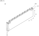
- FIG. 5 is a perspective view of the auxiliary partition wall 240 included in the battery pack according to the first embodiment of the present invention.
- both ends of the auxiliary partition wall 240 are coupled to the main partition wall 220 and the side wall 230.
- the auxiliary partition walls 240 are installed on both sides of the main partition wall 220 to be spaced a predetermined distance from each other in a longitudinal direction d of the main partition wall 220, and one auxiliary partition wall 240 is adjacent to two module areas A on both sides thereof.
- An interval between the auxiliary partition walls 240 may be approximately the same as a width of the battery module 100 being used. That is, both sides of the battery module 100 accommodated in the module area A may be inserted such that both sides thereof are in close contact with the auxiliary partition walls 240. Thus, both sides of the battery module 100 inserted into the module area A may be supported by the auxiliary partition walls 240.
- the auxiliary partition wall 240 includes a pair of reinforcement plates 241 coupled to each other, and the pair of reinforcement plates 241 are formed in a structure in which one sides, which face each other, of the reinforcement plates 241 are engaged.
- the reinforcement plate 241 includes a plurality of reinforcement ribs 2411 protruding from one side thereof and extending in the longitudinal direction d of the reinforcement plate 241, and when each of the reinforcement ribs 2411 is engaged with the reinforcement rib 2411 of the facing reinforcement plate 241, the pair of reinforcement plates 241 are coupled to each other to constitute the auxiliary partition wall 240.
- FIG. 6 illustrates a pair of separated reinforcement plates 241.
- the reinforcement rib 2411 may have a trapezoidal shape having slopes formed on both sides thereof or a parabolic shape (not illustrated).
- the reinforcement ribs 2411 are spaced a predetermined distance from each other in the longitudinal direction d of the reinforcement plate 241.
- the reinforcement plate 241 includes reinforcement grooves 2412 formed in a curved shape by inclined surfaces of the reinforcement ribs 2411 between the reinforcement ribs 2411 arranged adjacent to each other in the longitudinal direction d.
- the reinforcement grooves 2412 may have the same shape as the reinforcement ribs 2411 so that the reinforcement ribs 2411 may be engaged with and inserted into the reinforcement grooves 2412.
- the reinforcement grooves 2412 also have a trapezoidal shape.
- the reinforcement ribs 2411 and the reinforcement grooves 2412 may be alternately formed in the longitudinal direction d of the reinforcement plate 241.
- the reinforcement ribs 2411 are spaced a predetermined distance from each other in a height direction d2 of the reinforcement plate 241.
- FIG. 7 is a plan view of the pair of reinforcement plates 241 illustrated in FIG. 6 .
- the auxiliary partition wall 240 of the present invention includes a first reinforcement plate 241a positioned on one side thereof and a second reinforcement plate 241b positioned to face the first reinforcement plate 241a.
- the reinforcement ribs 2411 formed on the first reinforcement plate 241a and the second reinforcement plate 241b are formed at heights that are symmetrical to each other in the height direction d2 of the reinforcement plate 241 but are formed at positions misaligned from each other in the longitudinal direction d of the reinforcement plate 241.
- a reinforcement rib 241a1 of the first reinforcement plate 241a and the reinforcement groove 2412 of the second reinforcement plate 241b are positioned to face each other.
- the reinforcement rib 241a1 and the reinforcement groove of 2412 of the first reinforcement plate 241a are engaged with the reinforcement groove 2412 and a reinforcement rib 241bl of the second reinforcement plate 241b.
- FIG. 8 illustrates the auxiliary partition wall 240 in which the first reinforcement plate 241a and the second reinforcement plate 241b are coupled to each other.
- the first reinforcement plate 241a is coupled to the second reinforcement plate 241b so that the reinforcement rib 241a1 is inserted into the reinforcement groove 2412 of the second reinforcement plate 241b at a corresponding position
- the second reinforcement plate 241b is coupled to the first reinforcement plate 241a so that the reinforcement rib 241b1 is inserted into the reinforcement groove 2412 of the first reinforcement plate 241a at a corresponding position.
- the reinforcement ribs 2411 coupled to be misaligned with each other form a strip shape extending in the longitudinal direction d of the reinforcement plate 241. That is, inclined surfaces of the reinforcement ribs 2411, which are engaged with each other in a symmetrical shape, are in contact with each other to coincide with each other, to form one strip shape.
- a plurality of strips formed by coupling the reinforcement ribs 2411 in the height direction d2 of the reinforcement plate 241 may be formed in one auxiliary partition wall 240.
- a side surface of the battery module 100 accommodated in the battery pack of the present invention may be firmly supported by the reinforcement ribs 2411 forming one strip shape.
- the reinforcement plate 241 included in the battery pack according to the first embodiment of the present invention includes through holes 2411h perforated to perpendicularly pass through the reinforcement ribs 2411.
- the through holes 2411h are formed at the same position in the reinforcement ribs 2411.
- the through holes 2411h included in the reinforcement ribs 2411 formed in the height direction d2 of the reinforcement plate 241 at the same position in the longitudinal direction d of the reinforcement plate 241 are formed at positions corresponding to each other.
- One bolt B may be inserted into each of the through holes 2411h formed at the same position in the longitudinal direction d of the reinforcement plate 241, and the reinforcement plate 241 may be screw-coupled to the bolt B inserted into the through hole 2411h.
- the side surface of the battery module 100 accommodated in the module area A of the battery pack of the present invention may be primarily supported by the reinforcement plate 241 included in the auxiliary partition wall 240, and the side surface of the battery module 100 may be triply supported by the reinforcement ribs 2411 formed in the reinforcement plate 241 and the bolt B inserted into the through hole 2411h of the reinforcement rib 2411.
- the reinforcement plate 241 includes protrusions 243 that protrude upward from both ends thereof and includes auxiliary coupling holes 243h perforated to pass through the protrusions 243 in a horizontal direction.
- the bolt B may be inserted into the auxiliary coupling hole 243h, and the reinforcement plate 241 may be screw-coupled to the bolt B inserted into the auxiliary coupling hole 243h.
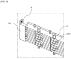
- FIG. 9 illustrates a state in which the bolt B is inserted into each of the through hole 2411h and the auxiliary coupling hole 243h of the one reinforcement plate 241. (However, for convenience, a detailed structure such as the thread of the bolt B is omitted.)
- one bolt B is inserted into and coupled to the through hole 2411h of each of the reinforcement ribs 2411 formed at the same position in the longitudinal direction d of the reinforcement plate 241.
- Another bolt B is inserted into and coupled to, in the horizontal direction, the auxiliary coupling hole 243h formed at an end of the reinforcement plate 241.
- the battery module 100 of the present invention may be fixed to the pack case 200 included in the battery pack by the bolts B inserted into and coupled to the through hole 2411h and the auxiliary coupling hole 243h.
- the auxiliary partition wall 240 may be fixedly coupled to the base plate 210 by a bolt B that perpendicularly passes through the through hole 2411h and is inserted into the coupling groove 210h of the base plate 210.
- the bolt B may be inserted into and coupled to each of the plurality of through holes 2411h spaced a predetermined distance from each other in the longitudinal direction d of the reinforcement plate 241.
- the bolt B inserted into the through hole 2411h allows the pair of reinforcement plates 241 constituting the auxiliary partition wall 240 to be fixed to the base plate 210.
- a swelling phenomenon in which the battery module 100 expands can be suppressed by the bolts B perpendicularly disposed along the side surface of the battery module 100 and the auxiliary partition walls 240 coupled to the base plate 210 by the bolts B.
- the auxiliary partition walls 240 may be installed such that the auxiliary coupling holes 243h of the reinforcement plates 241 correspond to the auxiliary coupling grooves 220h and 230h of the side wall 230 and the main partition wall 220.
- the auxiliary partition walls 240 may be fixedly coupled to the side wall 230 and the main partition wall 220 by the bolts B that horizontally pass through the auxiliary coupling hole 243h and are inserted into the auxiliary coupling grooves 220h and 230h.
- the auxiliary partition walls 240 installed inside the pack case 200 may be fixedly coupled to not only the side wall 230 and the main partition wall 220 but also the base plate 210 to support the battery module 100.
- the battery pack of the present invention may further include an upper cover (not illustrated) coupled to the pack case 200 to cover an upper portion of each battery module 100 accommodated in the module area A of the pack case 200.
- FIG. 10 is a view illustrating a pack case 200 included in a battery pack and a battery module 100 accommodated in the pack case 200 according to a second embodiment of the present invention.
- the battery pack according to the second embodiment of the present invention differs from the battery pack according to the first embodiment in terms of the structure of the auxiliary partition wall 240.
- configurations of the base plate 210, the main partition wall 220, and the side wall 230 are replaced with those according to the first embodiment.
- FIG. 11 illustrates a pair of reinforcement plates 241 constituting the auxiliary partition wall 240 included in the battery pack according to the second embodiment of the present invention.
- the auxiliary partition wall 240 has a structure in which the pair of arranged reinforcement plates 241 are coupled to each other.
- both ends of the auxiliary partition wall 240 are coupled to the main partition wall 220 and the side wall 230.
- the auxiliary partition wall 240 includes a pair of reinforcement plates 241, and one sides, which face each other, of the pair of reinforcement plates 241 are formed in a structure in which the reinforcement plates 241 are engaged.
- the reinforcement plate 241 includes a plurality of reinforcement ribs 2411 protruding from one side thereof and extending in the longitudinal direction d of the reinforcement plate 241, and as each of the reinforcement ribs 2411 is engaged with the reinforcement rib 2411 of the facing reinforcement plate 241, the pair of reinforcement plates 241 are coupled to each other to constitute the auxiliary partition wall 240.
- the reinforcement rib 2411 may have a trapezoidal shape having slopes formed on both sides thereof or a parabolic shape (not illustrated).
- the reinforcement ribs 2411 are spaced a predetermined distance from each other in the longitudinal direction d of the reinforcement plate 241.
- the reinforcement plate 241 includes reinforcement grooves 2412 formed in a curved shape by the inclined surfaces of the reinforcement ribs 2411 between the reinforcement ribs 2411 arranged adjacent to each other in the longitudinal direction d.
- the reinforcement grooves 2412 may have the same shape as the reinforcement ribs 2411 so that the reinforcement ribs 2411 may be engaged with and inserted into the reinforcement grooves 2412.
- the reinforcement grooves 2412 also have a trapezoidal shape.
- the reinforcement ribs 2411 and the reinforcement grooves 2412 may be alternately formed in the longitudinal direction d of the reinforcement plate 241.
- the reinforcement ribs 2411 are spaced a predetermined distance from each other in the height direction d2 of the reinforcement plate 241.
- the reinforcement plate 241 constituting the auxiliary partition wall 240 includes a first reinforcement plate 241a positioned on one side thereof and a second reinforcement plate 241b facing the first reinforcement plate 241a and coupled to the first reinforcement plate 241a.
- the reinforcement ribs 2411 formed on the first reinforcement plate 241a and the second reinforcement plate 241b are formed at heights that are symmetrical to each other in the height direction d2 of the reinforcement plate 241 but are formed at positions misaligned from each other in the longitudinal direction d of the reinforcement plate 241.
- the reinforcement rib 241a1 of the first reinforcement plate 241a and the reinforcement groove 2412 of the second reinforcement plate 241b are positioned to be symmetrical to each other.
- the auxiliary partition wall 240 included in the battery pack according to the second embodiment of the present invention further includes reinforcement bars 242 that extend perpendicularly through the reinforcement ribs 2411.
- the reinforcement bars 242 are formed on the reinforcement plate 241 to be spaced a predetermined distance from each other in the longitudinal direction d of the reinforcement plate 241.
- the reinforcement bars 242 may be formed at the same positions as the reinforcement ribs 2411.
- the reinforcement bar 242 includes a perpendicularly perforated reinforcement hole 242h.
- One bolt B may be inserted into the reinforcement hole 242h of the reinforcement bar 242, and the reinforcement plate 241 may be screw-coupled to the bolt B inserted into the reinforcement hole 242h.
- the battery module 100 accommodated in the battery pack of the present invention may be primarily supported by the reinforcement plate 241 and may be quadruply supported by the reinforcement ribs 2411 formed on the reinforcement plate 241, the perpendicularly extending reinforcement bars 242, and the bolts B inserted into the reinforcement holes 242h of the reinforcement bars 242.
- FIG. 12 illustrates the auxiliary partition wall 240 in which the first reinforcement plate 241a and the second reinforcement plate 241b are coupled to each other.
- the first reinforcement plate 241a is coupled to the second reinforcement plate 241b so that the reinforcement rib 241a1 is inserted into the reinforcement groove 2412 of the second reinforcement plate 241b at a corresponding position
- the second reinforcement plate 241b is coupled to the first reinforcement plate 241a so that the reinforcement rib 241b1 is inserted into the reinforcement groove 2412 of the first reinforcement plate 241a at a corresponding position.
- the reinforcement ribs 2411 coupled to be misaligned with each other form a strip shape extending in the longitudinal direction d of the reinforcement plate 241. That is, the inclined surfaces of the reinforcement ribs 2411, which are engaged with each other in a symmetrical shape, are in contact with each other to coincide with each other, to form one strip shape.
- a plurality of strips formed by coupling the reinforcement ribs 2411 in the height direction d2 of the reinforcement plate 241 may be formed in one auxiliary partition wall 240.
- the battery module 100 accommodated in the battery pack of the present invention can be firmly supported by the reinforcement ribs 2411 forming the one strip shape and the reinforcement bars 242 perpendicularly formed to intersect the plurality of reinforcement ribs 2411 forming the strip shape in the longitudinal direction d of the reinforcement plate 241.
- the reinforcement plate 241 includes protrusions 243 that protrude upward from both ends thereof and includes auxiliary coupling holes 243h perforated to pass through the protrusions 243 in the horizontal direction.
- the bolt B may be inserted into the auxiliary coupling hole 243h, and the reinforcement plate 241 may be screw-coupled to the bolt B inserted into the auxiliary coupling hole 243h.
- FIG. 13 illustrates a state in which the bolt B is inserted into each of the reinforcement hole 242h and the auxiliary coupling hole 243h of the one reinforcement plate 241. (However, for convenience, a detailed structure such as the thread of the bolt B is omitted.)
- one bolt B is inserted into and coupled to the reinforcement hole 242h of each of the reinforcement bars 242 formed at the same position in the longitudinal direction d of the reinforcement plate 241.
- Another bolt B is inserted into and coupled to, in the horizontal direction, the auxiliary coupling hole 243h formed at the end of the reinforcement plate 241.
- the battery module 100 of the present invention may be fixed to the pack case 200 included in the battery pack by the bolts B inserted into and coupled to the reinforcement hole 242h and the auxiliary coupling hole 243h.
- the auxiliary partition wall 240 may be fixedly coupled to the base plate 210 by a bolt B that perpendicularly passes through the reinforcement hole 242h and is inserted into the coupling groove 210h of the base plate 210.
- the bolt B may be inserted into and coupled to each of the plurality of reinforcement holes 242h spaced a predetermined distance from each other in the longitudinal direction d of the reinforcement plate 241.
- the bolt B inserted into the reinforcement hole 242h allows the pair of reinforcement plates 241 constituting the auxiliary partition wall 240 to be fixed to the base plate 210.
- the swelling phenomenon in which the battery module 100 expands can be suppressed by the bolts B perpendicularly disposed along the side surface of the battery module 100 and the auxiliary partition walls 240 coupled to the base plate 210 by the bolt B.
- the auxiliary partition walls 240 may be installed such that the auxiliary coupling holes 243h of the reinforcement plates 241 correspond to the auxiliary coupling grooves 220h and 230h of the side wall 230 and the main partition wall 220.
- the auxiliary partition walls 240 may be fixedly coupled to the side wall 230 and the main partition wall 220 by the bolts B that horizontally pass through the auxiliary coupling hole 243h and are inserted into the auxiliary coupling grooves 220h and 230h.
- the auxiliary partition walls 240 installed inside the pack case 200 may be fixedly coupled to not only the side wall 230 and the main partition wall 220 but also the base plate 210 to support the battery module 100.
- the battery pack of the present invention may further include an upper cover (not illustrated) coupled to the pack case 200 to cover an upper portion of each battery module 100 accommodated in the module area A of the pack case 200.
Landscapes
- Chemical & Material Sciences (AREA)
- Chemical Kinetics & Catalysis (AREA)
- Electrochemistry (AREA)
- General Chemical & Material Sciences (AREA)
- Battery Mounting, Suspending (AREA)
Abstract
Description
- The present invention relates to a battery pack.
- This application claims the benefit of priority based on
Korean Patent Application No. 10-2022-0059860, filed on May 16, 2022 - Types of secondary batteries include lithium ion batteries, lithium polymer batteries, nickel cadmium batteries, nickel hydrogen batteries, and nickel zinc batteries. An operating voltage of these unit secondary battery cells, that is, unit battery cells, is in a range of about 2.5 V to 4.2 V. Thus, when a higher output voltage is required, a battery pack is formed by connecting a plurality of battery cells in series. Further, a battery pack may be formed by connecting a plurality of battery cells in parallel according to a charging/discharging capacity required for the battery pack. Thus, the number of battery cells included in the battery pack may be variously set according to a required output voltage and a required charging/discharging capacity.
- For example, when a battery pack is formed by connecting a plurality of battery cells in series or parallel, a battery module including a plurality of battery cells is first formed.
-
FIG. 1 is a view illustrating a commonly usedbattery module 10 and apack case 20 included in a battery pack in which thebattery module 10 is accommodated. - Specifically, (a) of
FIG. 1 is a view illustrating one type of thebattery module 10. As illustrated, thebattery module 10 according to the related art has a shape in which thebattery module 10 has end plates 12 coupled to front and rear sides thereof and side surfaces thereof are surrounded and protected by a module frame 11. In recent years, thebattery module 10 in which the module frame 11 is excluded and an internal cell is exposed is also being used. - Also, (b) of
FIG. 1 is a view illustrating thepack case 20 that provides a space, in which thebattery module 10 is accommodated, among common battery packs. A lower portion of eachbattery module 10 is supported by a base plate 21 in a space partitioned by a side wall 22 and a partition wall 23 in thepack case 20 illustrated in (b) ofFIG. 1 , and thus thebattery module 10 is electrically connected toother battery modules 10 in series or parallel. - Meanwhile, an abnormal phenomenon may occur in the battery module included in the battery pack during a charging or discharging process, and one example thereof is a swelling phenomenon. The swelling phenomenon is a phenomenon in which a battery cell expands due to gas generated inside the battery cell. The swelling phenomenon may first progress in each battery cell unit accommodated in the battery module, consequently affecting the battery module. In particular, the swelling phenomenon may progress throughout a central portion of the battery module, that is, the entire module frame. Generally, a portion of the module frame of each battery module accommodated in the pack case is not a particularly fixed portion, and thus when the swelling phenomenon severely occurs, the swelling phenomenon may affect adjacent battery modules.
- Thus, there is a need for a novel method capable of minimizing shape deformation of the battery module as much as possible even when the swelling phenomenon occurs in each battery module accommodated in the pack case.
-
Korean Patent Application Publication No. 10-2018-0113906 - Thus, an aspect of the present invention is to provide a structure capable of reinforcing a side surface of a battery module accommodated in a pack case.
- Further, another aspect of the present invention is to suppress a swelling phenomenon of the battery module accommodated in a pack case.
- Other purposes and advantages of the present invention may be understood with the following description and may be more clearly understood with embodiments of the present invention. Further, it will be readily apparent that the purposes and advantages of the present invention may be implemented by units and combinations thereof described in the appended claims.
- A battery pack for accommodating a battery module including a cell stack in which a plurality of cells are stacked includes a pack case including a module area where the battery module is placed, wherein the pack case includes a base plate that supports a lower portion of the battery module, a main partition wall extending across the base plate and perpendicularly coupled to a central portion of the base plate, a side wall perpendicularly coupled to an edge of the base plate along a perimeter of the base plate, and an auxiliary partition wall of which opposite ends are coupled to the main partition wall and the side wall, respectively, and which includes a pair of reinforcement plates coupled to each other, and wherein a reinforcement plate of the pair of reinforcement plates includes a plurality of reinforcement ribs protruding and extending in a longitudinal direction of the reinforcement plate.
- The plurality of reinforcement ribs may be spaced at a predetermined distance from each other in the longitudinal direction of the reinforcement plate.
- The reinforcement plate may include a reinforcement groove having a curved shape between a pair of reinforcement ribs spaced apart from each other in the longitudinal direction of the reinforcement plate from among the plurality of reinforcement ribs.
- A shape of the reinforcement groove may be the same as a shape of a reinforcement rib from among the pair of reinforcement ribs so that the reinforcement rib is engaged with and inserted into the reinforcement groove.
- The reinforcement rib and the reinforcement groove may be alternately formed in a longitudinal direction of the auxiliary partition wall.
- The plurality of reinforcement ribs may have at least one of a trapezoidal shape and a parabolic shape.
- The plurality of reinforcement ribs may be spaced at a predetermined distance from each other in a height direction of the pair of reinforcement plates.
- The auxiliary partition wall may include a first reinforcement plate having a reinforcement rib formed on one side thereof from among the plurality of reinforcement ribs, and a second reinforcement plate having a reinforcement rib formed on one side thereof facing the first reinforcement plate from among the plurality of reinforcement ribs, and the reinforcement ribs included in the first reinforcement plate and the second reinforcement plate may be formed at heights corresponding to each other.
- Each of the first reinforcement plate and the second reinforcement plate may include a reinforcement groove having a curved shape between a pair of reinforcement ribs spaced apart from each other in the longitudinal direction of the first or second reinforcement plate from among the plurality of reinforcement ribs, and wherein the reinforcement rib and the reinforcement groove of the first reinforcement plate may be engaged with and coupled to the reinforcement groove and the reinforcement rib of the second reinforcement plate.
- The first reinforcement plate may be coupled to the second reinforcement plate so that the reinforcement rib of the first reinforcement plate is inserted into the reinforcement groove of the second reinforcement plate at a corresponding position, and the second reinforcement plate may be coupled to the first reinforcement plate so that the reinforcement rib of the second reinforcement plate is inserted into the reinforcement groove of the first reinforcement plate at a corresponding position.
- The reinforcement plate may include a through hole perforated to perpendicularly pass through a reinforcement rib from among the plurality of reinforcement ribs.
- The pack case may further include a coupling groove formed at a bottom of the module area to correspond to a position of the through hole, and the auxiliary partition wall may be coupled to the pack case by a bolt passing through the through hole and inserted into the coupling groove.
- The reinforcement plate may further include a reinforcement bar extending perpendicularly through a reinforcement rib from among the plurality of reinforcement ribs, and the reinforcement bar may include a reinforcement hole perforated to perpendicularly pass through the reinforcement bar.
- The pack case may include a coupling groove formed at a bottom of the module area to correspond to a position of the reinforcement hole, and the auxiliary partition wall may be coupled to the pack case by a bolt passing through the reinforcement hole and inserted into the coupling groove.
- The reinforcement plate may include auxiliary coupling holes perforated to pass through opposite ends of the reinforcement plate in a horizontal direction, each of the side wall and the main partition wall may include an auxiliary coupling groove formed to correspond to a position of an auxiliary coupling hole of the auxiliary coupling holes of the auxiliary partition wall, and the auxiliary partition wall may be coupled to the pack case by a bolt passing through the auxiliary coupling hole and inserted into the auxiliary coupling groove.
- According to the present invention, a swelling phenomenon of a battery module accommodated in a pack case can be suppressed.
- Further, the present invention can improve the assembly efficiency of a pack case by using a structure capable of dividing a battery module accommodated in the pack case and being freely attached to or detached from the pack case.
-
-
FIG. 1 illustrates a battery module and a pack case according to a related art. -
FIG. 2 is a perspective view of a pack case included in a battery pack according to a first embodiment of the present invention. -
FIG. 3 illustrates a state in which a battery module is accommodated in the pack case ofFIG. 2 . -
FIG. 4 illustrates the pack case from which an auxiliary partition wall is detached. -
FIG. 5 is a perspective view of the auxiliary partition wall included in the battery pack according to the first embodiment of the present invention. -
FIG. 6 illustrates a pair of separated reinforcement plates. -
FIG. 7 is a plan view of the pair of reinforcement plates illustrated inFIG. 6 . -
FIG. 8 illustrates the auxiliary partition wall in which a first reinforcement plate and a second reinforcement plate are coupled. -
FIG. 9 illustrates a state in which bolts are inserted into a through hole and an auxiliary coupling hole. -
FIG. 10 is a view illustrating a pack case included in a battery pack and a battery module accommodated in the pack case according to a second embodiment of the present invention. -
FIG. 11 illustrates a pair of reinforcement plates constituting an auxiliary partition wall included in the battery pack according to the second embodiment of the present invention. -
FIG. 12 illustrates the auxiliary partition wall in which a first reinforcement plate and a second reinforcement plate are coupled. -
FIG. 13 illustrates a state in which bolts are inserted into a reinforcement hole and an auxiliary coupling hole. - Hereinafter, exemplary embodiments of the present invention will be described in detail with reference to the accompanying drawings. Prior to this, terms or words used in the present specification and the appended claims should not be interpreted as being limited to usual or dictionary meanings and should be interpreted as meanings and concepts corresponding to the technical spirit of the present invention according to the principle that the inventor may properly define the concepts of the terms in order to describe his/her own invention in the best way.
- Thus, since the embodiments described in the present specification and configurations illustrated in the drawings are merely the most exemplary embodiments of the present invention and do not represent all the technical spirit of the present invention, it should be understood that there may be various equivalents and variations that may replace the embodiments and the configurations at the time of filing the present application.
- Further, in description of the present invention, when it is determined that the detailed description of widely known related configurations or functions may obscure the gist of the present invention, the detailed description will be omitted.
- Since the embodiments of the present invention are provided to more completely describe the present invention to those skilled in the art, the shapes and sizes of components in the drawings may be exaggerated, omitted, or schematically illustrated for clearer description. Thus, the size or ratio of each component does not entirely reflect the actual size or ratio.
- The present invention relates to a battery pack for accommodating a battery module including a cell stack in which a plurality of cells are stacked.
- The battery module accommodated in the battery pack of the present invention may include the cell stack and end plates coupled to front and rear sides of the cell stack or may further include a module frame surrounding the side surfaces and the upper and lower surfaces of the cell stack.
- The battery pack of the present invention includes a pack case including a module area where the battery module is placed.
-
FIGS. 2 to 9 relate to a battery pack according to a first embodiment of the present invention, andFIGS. 10 to 13 relate to a battery pack according to a second embodiment of the present invention. - Hereinafter, each embodiment will be described with reference to the accompanying drawings.
-
FIG. 2 is a perspective view of apack case 200 included in the battery pack according to the first embodiment of the present invention, andFIG. 3 illustrates a state in which abattery module 100 is accommodated in thepack case 200 ofFIG. 2 . - As illustrated in
FIGS. 2 and3 , thepack case 200 includes abase plate 210, amain partition wall 220, aside wall 230, and anauxiliary partition wall 240. - The
auxiliary partition wall 240 of the present invention is detachably installed on thebase plate 210 and theside wall 230 of thepack case 200. -
FIG. 4 illustrates thepack case 200 from which theauxiliary partition wall 240 is detached. - According to
FIGS. 2 to 4 , thebase plate 210 corresponds to a bottom of thepack case 200 and serves to support a lower portion of thebattery module 100 mounted thereon. - A
coupling groove 210h may be formed in thebase plate 210 so that a bolt B may inserted into and screw-coupled to thecoupling groove 210h. - The
main partition wall 220 extends across thebase plate 210 and is perpendicularly coupled to a central portion of thebase plate 210. - The
battery modules 100 seated on both sides of themain partition wall 220 are symmetrical to each other with respect to themain partition wall 220. - The
main partition wall 220 may serve to roughly divide an inner space of thepack case 200 into two areas and also serve to protect various conducting wires used inside thepack case 200 by inserting the conducting wires into themain partition wall 220. - The
side wall 230 is perpendicularly coupled to an edge of thebase plate 210 in a perimeter direction and serves to surround and protect an outer surface of thebattery module 100 positioned on thebase plate 210. -
Auxiliary coupling grooves main partition wall 220 and theside wall 230 so that the bolts B are inserted into and screw-coupled to theauxiliary coupling grooves -
FIG. 5 is a perspective view of theauxiliary partition wall 240 included in the battery pack according to the first embodiment of the present invention. - As illustrated in
FIG. 2 , both ends of theauxiliary partition wall 240 are coupled to themain partition wall 220 and theside wall 230. - The
auxiliary partition walls 240 are installed on both sides of themain partition wall 220 to be spaced a predetermined distance from each other in a longitudinal direction d of themain partition wall 220, and oneauxiliary partition wall 240 is adjacent to two module areas A on both sides thereof. - An interval between the
auxiliary partition walls 240 may be approximately the same as a width of thebattery module 100 being used. That is, both sides of thebattery module 100 accommodated in the module area A may be inserted such that both sides thereof are in close contact with theauxiliary partition walls 240. Thus, both sides of thebattery module 100 inserted into the module area A may be supported by theauxiliary partition walls 240. - As illustrated in
FIG. 5 , theauxiliary partition wall 240 includes a pair ofreinforcement plates 241 coupled to each other, and the pair ofreinforcement plates 241 are formed in a structure in which one sides, which face each other, of thereinforcement plates 241 are engaged. - In detail, the
reinforcement plate 241 includes a plurality ofreinforcement ribs 2411 protruding from one side thereof and extending in the longitudinal direction d of thereinforcement plate 241, and when each of thereinforcement ribs 2411 is engaged with thereinforcement rib 2411 of the facingreinforcement plate 241, the pair ofreinforcement plates 241 are coupled to each other to constitute theauxiliary partition wall 240. -
FIG. 6 illustrates a pair of separatedreinforcement plates 241. - The
reinforcement rib 2411 may have a trapezoidal shape having slopes formed on both sides thereof or a parabolic shape (not illustrated). - Referring to
FIG. 6 , thereinforcement ribs 2411 are spaced a predetermined distance from each other in the longitudinal direction d of thereinforcement plate 241. - The
reinforcement plate 241 includesreinforcement grooves 2412 formed in a curved shape by inclined surfaces of thereinforcement ribs 2411 between thereinforcement ribs 2411 arranged adjacent to each other in the longitudinal direction d. In this case, thereinforcement grooves 2412 may have the same shape as thereinforcement ribs 2411 so that thereinforcement ribs 2411 may be engaged with and inserted into thereinforcement grooves 2412. For example, when thereinforcement ribs 2411 have a trapezoidal shape, thereinforcement grooves 2412 also have a trapezoidal shape. - The
reinforcement ribs 2411 and thereinforcement grooves 2412 may be alternately formed in the longitudinal direction d of thereinforcement plate 241. - Further, as illustrated in
FIG. 6 , thereinforcement ribs 2411 are spaced a predetermined distance from each other in a height direction d2 of thereinforcement plate 241. -
FIG. 7 is a plan view of the pair ofreinforcement plates 241 illustrated inFIG. 6 . - As illustrated in
FIG. 7 , theauxiliary partition wall 240 of the present invention includes afirst reinforcement plate 241a positioned on one side thereof and asecond reinforcement plate 241b positioned to face thefirst reinforcement plate 241a. - The
reinforcement ribs 2411 formed on thefirst reinforcement plate 241a and thesecond reinforcement plate 241b are formed at heights that are symmetrical to each other in the height direction d2 of thereinforcement plate 241 but are formed at positions misaligned from each other in the longitudinal direction d of thereinforcement plate 241. For example, a reinforcement rib 241a1 of thefirst reinforcement plate 241a and thereinforcement groove 2412 of thesecond reinforcement plate 241b are positioned to face each other. Thus, in theauxiliary partition wall 240 of the present invention formed by coupling thefirst reinforcement plate 241a and thesecond reinforcement plate 241b, the reinforcement rib 241a1 and the reinforcement groove of 2412 of thefirst reinforcement plate 241a are engaged with thereinforcement groove 2412 and a reinforcement rib 241bl of thesecond reinforcement plate 241b. -
FIG. 8 illustrates theauxiliary partition wall 240 in which thefirst reinforcement plate 241a and thesecond reinforcement plate 241b are coupled to each other. Referring toFIG. 8 , thefirst reinforcement plate 241a is coupled to thesecond reinforcement plate 241b so that the reinforcement rib 241a1 is inserted into thereinforcement groove 2412 of thesecond reinforcement plate 241b at a corresponding position, and thesecond reinforcement plate 241b is coupled to thefirst reinforcement plate 241a so that the reinforcement rib 241b1 is inserted into thereinforcement groove 2412 of thefirst reinforcement plate 241a at a corresponding position. - In this case, the
reinforcement ribs 2411 coupled to be misaligned with each other form a strip shape extending in the longitudinal direction d of thereinforcement plate 241. That is, inclined surfaces of thereinforcement ribs 2411, which are engaged with each other in a symmetrical shape, are in contact with each other to coincide with each other, to form one strip shape. Thus, a plurality of strips formed by coupling thereinforcement ribs 2411 in the height direction d2 of thereinforcement plate 241 may be formed in oneauxiliary partition wall 240. - Due to the above structure, as illustrated in
FIG. 3 , a side surface of thebattery module 100 accommodated in the battery pack of the present invention may be firmly supported by thereinforcement ribs 2411 forming one strip shape. - As illustrated in
FIGS. 6 to 8 , thereinforcement plate 241 included in the battery pack according to the first embodiment of the present invention includes throughholes 2411h perforated to perpendicularly pass through thereinforcement ribs 2411. - The through
holes 2411h are formed at the same position in thereinforcement ribs 2411. For example, the throughholes 2411h included in thereinforcement ribs 2411 formed in the height direction d2 of thereinforcement plate 241 at the same position in the longitudinal direction d of thereinforcement plate 241 are formed at positions corresponding to each other. - One bolt B may be inserted into each of the through
holes 2411h formed at the same position in the longitudinal direction d of thereinforcement plate 241, and thereinforcement plate 241 may be screw-coupled to the bolt B inserted into the throughhole 2411h. - The side surface of the
battery module 100 accommodated in the module area A of the battery pack of the present invention may be primarily supported by thereinforcement plate 241 included in theauxiliary partition wall 240, and the side surface of thebattery module 100 may be triply supported by thereinforcement ribs 2411 formed in thereinforcement plate 241 and the bolt B inserted into the throughhole 2411h of thereinforcement rib 2411. - As illustrated in
FIGS. 6 and8 , thereinforcement plate 241 includesprotrusions 243 that protrude upward from both ends thereof and includesauxiliary coupling holes 243h perforated to pass through theprotrusions 243 in a horizontal direction. - The bolt B may be inserted into the
auxiliary coupling hole 243h, and thereinforcement plate 241 may be screw-coupled to the bolt B inserted into theauxiliary coupling hole 243h. -
FIG. 9 illustrates a state in which the bolt B is inserted into each of the throughhole 2411h and theauxiliary coupling hole 243h of the onereinforcement plate 241. (However, for convenience, a detailed structure such as the thread of the bolt B is omitted.) - Referring to
FIG. 9 , one bolt B is inserted into and coupled to the throughhole 2411h of each of thereinforcement ribs 2411 formed at the same position in the longitudinal direction d of thereinforcement plate 241. - Further, another bolt B is inserted into and coupled to, in the horizontal direction, the
auxiliary coupling hole 243h formed at an end of thereinforcement plate 241. - The
battery module 100 of the present invention may be fixed to thepack case 200 included in the battery pack by the bolts B inserted into and coupled to the throughhole 2411h and theauxiliary coupling hole 243h. - In this detail, the
auxiliary partition wall 240 may be fixedly coupled to thebase plate 210 by a bolt B that perpendicularly passes through the throughhole 2411h and is inserted into thecoupling groove 210h of thebase plate 210. The bolt B may be inserted into and coupled to each of the plurality of throughholes 2411h spaced a predetermined distance from each other in the longitudinal direction d of thereinforcement plate 241. - The bolt B inserted into the through
hole 2411h allows the pair ofreinforcement plates 241 constituting theauxiliary partition wall 240 to be fixed to thebase plate 210. Thus, even when gas is generated inside thebattery module 100 accommodated in the module area A between theauxiliary partition walls 240, a swelling phenomenon in which thebattery module 100 expands can be suppressed by the bolts B perpendicularly disposed along the side surface of thebattery module 100 and theauxiliary partition walls 240 coupled to thebase plate 210 by the bolts B. - The
auxiliary partition walls 240 may be installed such that theauxiliary coupling holes 243h of thereinforcement plates 241 correspond to theauxiliary coupling grooves side wall 230 and themain partition wall 220. In this case, theauxiliary partition walls 240 may be fixedly coupled to theside wall 230 and themain partition wall 220 by the bolts B that horizontally pass through theauxiliary coupling hole 243h and are inserted into theauxiliary coupling grooves auxiliary partition walls 240 installed inside thepack case 200 may be fixedly coupled to not only theside wall 230 and themain partition wall 220 but also thebase plate 210 to support thebattery module 100. - The battery pack of the present invention may further include an upper cover (not illustrated) coupled to the
pack case 200 to cover an upper portion of eachbattery module 100 accommodated in the module area A of thepack case 200. - Since the upper cover corresponds to widely-known technology, a more detailed description thereof will be omitted.
-
FIG. 10 is a view illustrating apack case 200 included in a battery pack and abattery module 100 accommodated in thepack case 200 according to a second embodiment of the present invention. - The battery pack according to the second embodiment of the present invention differs from the battery pack according to the first embodiment in terms of the structure of the
auxiliary partition wall 240. Thus, configurations of thebase plate 210, themain partition wall 220, and theside wall 230 are replaced with those according to the first embodiment. -
FIG. 11 illustrates a pair ofreinforcement plates 241 constituting theauxiliary partition wall 240 included in the battery pack according to the second embodiment of the present invention. - The
auxiliary partition wall 240 has a structure in which the pair of arrangedreinforcement plates 241 are coupled to each other. - Like the
auxiliary partition wall 240 of the battery pack according to the first embodiment, both ends of theauxiliary partition wall 240 are coupled to themain partition wall 220 and theside wall 230. - As illustrated in
FIG. 11 , theauxiliary partition wall 240 includes a pair ofreinforcement plates 241, and one sides, which face each other, of the pair ofreinforcement plates 241 are formed in a structure in which thereinforcement plates 241 are engaged. - In detail, the
reinforcement plate 241 includes a plurality ofreinforcement ribs 2411 protruding from one side thereof and extending in the longitudinal direction d of thereinforcement plate 241, and as each of thereinforcement ribs 2411 is engaged with thereinforcement rib 2411 of the facingreinforcement plate 241, the pair ofreinforcement plates 241 are coupled to each other to constitute theauxiliary partition wall 240. - The
reinforcement rib 2411 may have a trapezoidal shape having slopes formed on both sides thereof or a parabolic shape (not illustrated). - Referring to
FIG. 11 , thereinforcement ribs 2411 are spaced a predetermined distance from each other in the longitudinal direction d of thereinforcement plate 241. - The
reinforcement plate 241 includesreinforcement grooves 2412 formed in a curved shape by the inclined surfaces of thereinforcement ribs 2411 between thereinforcement ribs 2411 arranged adjacent to each other in the longitudinal direction d. In this case, thereinforcement grooves 2412 may have the same shape as thereinforcement ribs 2411 so that thereinforcement ribs 2411 may be engaged with and inserted into thereinforcement grooves 2412. For example, when thereinforcement ribs 2411 have a trapezoidal shape, thereinforcement grooves 2412 also have a trapezoidal shape. - The
reinforcement ribs 2411 and thereinforcement grooves 2412 may be alternately formed in the longitudinal direction d of thereinforcement plate 241. - Further, as illustrated in
FIG. 11 , thereinforcement ribs 2411 are spaced a predetermined distance from each other in the height direction d2 of thereinforcement plate 241. - The
reinforcement plate 241 constituting theauxiliary partition wall 240 includes afirst reinforcement plate 241a positioned on one side thereof and asecond reinforcement plate 241b facing thefirst reinforcement plate 241a and coupled to thefirst reinforcement plate 241a. - The
reinforcement ribs 2411 formed on thefirst reinforcement plate 241a and thesecond reinforcement plate 241b are formed at heights that are symmetrical to each other in the height direction d2 of thereinforcement plate 241 but are formed at positions misaligned from each other in the longitudinal direction d of thereinforcement plate 241. For example, the reinforcement rib 241a1 of thefirst reinforcement plate 241a and thereinforcement groove 2412 of thesecond reinforcement plate 241b are positioned to be symmetrical to each other. - As illustrated in
FIG. 11 , theauxiliary partition wall 240 included in the battery pack according to the second embodiment of the present invention further includes reinforcement bars 242 that extend perpendicularly through thereinforcement ribs 2411. - The reinforcement bars 242 are formed on the
reinforcement plate 241 to be spaced a predetermined distance from each other in the longitudinal direction d of thereinforcement plate 241. The reinforcement bars 242 may be formed at the same positions as thereinforcement ribs 2411. - The
reinforcement bar 242 includes a perpendicularly perforated reinforcement hole 242h. - One bolt B may be inserted into the reinforcement hole 242h of the
reinforcement bar 242, and thereinforcement plate 241 may be screw-coupled to the bolt B inserted into the reinforcement hole 242h. Thus, thebattery module 100 accommodated in the battery pack of the present invention may be primarily supported by thereinforcement plate 241 and may be quadruply supported by thereinforcement ribs 2411 formed on thereinforcement plate 241, the perpendicularly extending reinforcement bars 242, and the bolts B inserted into the reinforcement holes 242h of the reinforcement bars 242. -
FIG. 12 illustrates theauxiliary partition wall 240 in which thefirst reinforcement plate 241a and thesecond reinforcement plate 241b are coupled to each other. According toFIG. 12 , thefirst reinforcement plate 241a is coupled to thesecond reinforcement plate 241b so that the reinforcement rib 241a1 is inserted into thereinforcement groove 2412 of thesecond reinforcement plate 241b at a corresponding position, and thesecond reinforcement plate 241b is coupled to thefirst reinforcement plate 241a so that the reinforcement rib 241b1 is inserted into thereinforcement groove 2412 of thefirst reinforcement plate 241a at a corresponding position. - In this case, the
reinforcement ribs 2411 coupled to be misaligned with each other form a strip shape extending in the longitudinal direction d of thereinforcement plate 241. That is, the inclined surfaces of thereinforcement ribs 2411, which are engaged with each other in a symmetrical shape, are in contact with each other to coincide with each other, to form one strip shape. Thus, a plurality of strips formed by coupling thereinforcement ribs 2411 in the height direction d2 of thereinforcement plate 241 may be formed in oneauxiliary partition wall 240. - Due to the structure described above, the
battery module 100 accommodated in the battery pack of the present invention can be firmly supported by thereinforcement ribs 2411 forming the one strip shape and the reinforcement bars 242 perpendicularly formed to intersect the plurality ofreinforcement ribs 2411 forming the strip shape in the longitudinal direction d of thereinforcement plate 241. - As illustrated in
FIGS. 11 and12 , thereinforcement plate 241 includesprotrusions 243 that protrude upward from both ends thereof and includesauxiliary coupling holes 243h perforated to pass through theprotrusions 243 in the horizontal direction. - The bolt B may be inserted into the
auxiliary coupling hole 243h, and thereinforcement plate 241 may be screw-coupled to the bolt B inserted into theauxiliary coupling hole 243h. -
FIG. 13 illustrates a state in which the bolt B is inserted into each of the reinforcement hole 242h and theauxiliary coupling hole 243h of the onereinforcement plate 241. (However, for convenience, a detailed structure such as the thread of the bolt B is omitted.) - Referring to
FIG. 13 , one bolt B is inserted into and coupled to the reinforcement hole 242h of each of the reinforcement bars 242 formed at the same position in the longitudinal direction d of thereinforcement plate 241. - Further, another bolt B is inserted into and coupled to, in the horizontal direction, the
auxiliary coupling hole 243h formed at the end of thereinforcement plate 241. - The
battery module 100 of the present invention may be fixed to thepack case 200 included in the battery pack by the bolts B inserted into and coupled to the reinforcement hole 242h and theauxiliary coupling hole 243h. - In detail, the
auxiliary partition wall 240 may be fixedly coupled to thebase plate 210 by a bolt B that perpendicularly passes through the reinforcement hole 242h and is inserted into thecoupling groove 210h of thebase plate 210. The bolt B may be inserted into and coupled to each of the plurality of reinforcement holes 242h spaced a predetermined distance from each other in the longitudinal direction d of thereinforcement plate 241. - The bolt B inserted into the reinforcement hole 242h allows the pair of
reinforcement plates 241 constituting theauxiliary partition wall 240 to be fixed to thebase plate 210. Thus, even when gas is generated inside thebattery module 100 accommodated in the module area A between theauxiliary partition walls 240, the swelling phenomenon in which thebattery module 100 expands can be suppressed by the bolts B perpendicularly disposed along the side surface of thebattery module 100 and theauxiliary partition walls 240 coupled to thebase plate 210 by the bolt B. - The
auxiliary partition walls 240 may be installed such that theauxiliary coupling holes 243h of thereinforcement plates 241 correspond to theauxiliary coupling grooves side wall 230 and themain partition wall 220. In this case, theauxiliary partition walls 240 may be fixedly coupled to theside wall 230 and themain partition wall 220 by the bolts B that horizontally pass through theauxiliary coupling hole 243h and are inserted into theauxiliary coupling grooves auxiliary partition walls 240 installed inside thepack case 200 may be fixedly coupled to not only theside wall 230 and themain partition wall 220 but also thebase plate 210 to support thebattery module 100. - The battery pack of the present invention may further include an upper cover (not illustrated) coupled to the
pack case 200 to cover an upper portion of eachbattery module 100 accommodated in the module area A of thepack case 200. - Since the upper cover corresponds to widely-known technology, a more detailed description thereof will be omitted.
- Hereinabove, the present invention has been described in more detail through the drawings, the embodiments, and the like. However, since configurations described in the drawings or the embodiments described in the present specification are merely embodiments of the present invention and do not represent all the technical spirit of the present invention, it should be understood that there may be various equivalents and variations that may replace the configurations are present at the time of filing the present application.
-
- 10: (Related Art) Battery module
- 11: (Related Art) Module frame
- 12: (Related Art) End plate
- 20: (Related Art) Pack case
- 21: (Related Art) Base plate
- 22: (Related Art) Side wall
- 23: (Related Art) Partition wall
- 100: Battery module
- 200: Pack case
- 210: Base plate
- 210h: Coupling groove
- 220: Main partition wall
- 230: Side wall
- 220h, 230h: Auxiliary coupling groove
- 240: Auxiliary partition wall
- 241: Reinforcement plate
- 241a: First reinforcement plate
- 241a1: Reinforcement rib of first reinforcement plate
- 241b: Second reinforcement plate
- 241b1: Reinforcement rib of second reinforcement plate
- 2411: Reinforcement rib
- 2411h: Through hole
- 2412: Reinforcement groove
- 242: Reinforcement bar
- 242h: Reinforcement hole
- 243: Protrusion
- 243h: Auxiliary coupling hole
- A: Module area
- B: Bolt
- d: Longitudinal direction of reinforcement plate
- d2: Height direction of reinforcement plate
Claims (15)
- A battery pack for accommodating a battery module including a cell stack in which a plurality of cells are stacked, the battery pack comprising:a pack case including a module area where the battery module is placed,wherein the pack case includes:a base plate configured to support a lower portion of the battery module;a main partition wall extending across the base plate and perpendicularly coupled to a central portion of the base plate;a side wall perpendicularly coupled to an edge of the base plate along a perimeter of the base plate; andan auxiliary partition wall of which opposite ends are coupled to the main partition wall and the side wall, respectively, and which includes a pair of reinforcement plates coupled to each other, andwherein a reinforcement plate of the pair of reinforcement plates includes a plurality of reinforcement ribs protruding and extending in a longitudinal direction of the reinforcement plate.
- The battery pack of claim 1, wherein the plurality of reinforcement ribs are spaced at a predetermined distance from each other in the longitudinal direction of the reinforcement plate.
- The battery pack of claim 2, wherein the reinforcement plate includes a reinforcement groove having a recessed shape between a pair of reinforcement ribs spaced apart from each other in the longitudinal direction of the reinforcement plate from among the plurality of reinforcement ribs.
- The battery pack of claim 3, wherein a shape of the reinforcement groove is the same as a shape of a reinforcement rib from among the pair of reinforcement ribs so that the reinforcement rib is engaged with and inserted into the reinforcement groove.
- The battery pack of claim 4, wherein the reinforcement rib and the reinforcement groove are alternately provided in a longitudinal direction of the auxiliary partition wall.
- The battery pack of claim 1, wherein the plurality of reinforcement ribs have at least one of a trapezoidal shape and a parabolic shape.
- The battery pack of claim 1, wherein the plurality of reinforcement ribs are spaced at a predetermined distance from each other in a height direction of the pair of reinforcement plates.
- The battery pack of claim 7, wherein the auxiliary partition wall includes:a first reinforcement plate of the pair of reinforcement plates, and having a reinforcement rib formed on one side thereof from among the plurality of reinforcement ribs; anda second reinforcement plate of the pair of reinforcement plates, and having a reinforcement rib formed on one side thereof facing the first reinforcement plate from among the plurality of reinforcement ribs, andwherein the reinforcement ribs included in the first reinforcement plate and the second reinforcement plate are formed at heights corresponding to each other.
- The battery pack of claim 8, wherein each of the first reinforcement plate and the second reinforcement plate includes a reinforcement groove having a recessed shape between a pair of reinforcement ribs spaced apart from each other in the longitudinal direction of the first or second reinforcement plate from among the plurality of reinforcement ribs, and
wherein the reinforcement rib and the reinforcement groove of the first reinforcement plate are engaged with and coupled to the reinforcement groove and the reinforcement rib of the second reinforcement plate. - The battery pack of claim 8, wherein the first reinforcement plate is coupled to the second reinforcement plate so that the reinforcement rib of the first reinforcement plate is inserted into the reinforcement groove of the second reinforcement plate at a corresponding position, and
wherein the second reinforcement plate is coupled to the first reinforcement plate so that the reinforcement rib of the second reinforcement plate is inserted into the reinforcement groove of the first reinforcement plate at a corresponding position. - The battery pack of claim 1, wherein the reinforcement plate includes a through hole perforated to perpendicularly pass through a reinforcement rib from among the plurality of reinforcement ribs.
- The battery pack of claim 11, wherein the pack case further includes a coupling groove formed at a bottom of the module area to correspond to a position of the through hole, and
wherein the auxiliary partition wall is coupled to the pack case by a bolt passing through the through hole and inserted into the coupling groove. - The battery pack of claim 1, wherein the reinforcement plate further includes a reinforcement bar extending perpendicularly through a reinforcement rib from among the plurality of reinforcement ribs, and
wherein the reinforcement bar includes a reinforcement hole perforated to perpendicularly pass through the reinforcement bar. - The battery pack of claim 13, wherein the pack case includes a coupling groove formed at a bottom of the module area to correspond to a position of the reinforcement hole, and
wherein the auxiliary partition wall is coupled to the pack case by a bolt passing through the reinforcement hole and inserted into the coupling groove. - The battery pack of claim 1, wherein the reinforcement plate includes auxiliary coupling holes perforated to pass through opposite ends of the reinforcement plate in a horizontal direction,wherein each of the side wall and the main partition wall includes an auxiliary coupling groove formed to correspond to a position of an auxiliary coupling hole of the auxiliary coupling holes of the auxiliary partition wall, andwherein the auxiliary partition wall is coupled to the pack case by a bolt passing through the auxiliary coupling hole and inserted into the auxiliary coupling groove.
Priority Applications (1)
| Application Number | Priority Date | Filing Date | Title |
|---|---|---|---|
| EP26160429.2A EP4726891A3 (en) | 2022-05-16 | 2023-05-16 | Battery pack |
Applications Claiming Priority (2)
| Application Number | Priority Date | Filing Date | Title |
|---|---|---|---|
| KR1020220059860A KR102639410B1 (en) | 2022-05-16 | 2022-05-16 | Battery pack |
| PCT/KR2023/006608 WO2023224354A1 (en) | 2022-05-16 | 2023-05-16 | Battery pack |
Related Child Applications (2)
| Application Number | Title | Priority Date | Filing Date |
|---|---|---|---|
| EP26160429.2A Division EP4726891A3 (en) | 2022-05-16 | 2023-05-16 | Battery pack |
| EP26160429.2A Division-Into EP4726891A3 (en) | 2022-05-16 | 2023-05-16 | Battery pack |
Publications (3)
| Publication Number | Publication Date |
|---|---|
| EP4407770A1 true EP4407770A1 (en) | 2024-07-31 |
| EP4407770A4 EP4407770A4 (en) | 2025-03-05 |
| EP4407770B1 EP4407770B1 (en) | 2026-04-22 |
Family
ID=88835738
Family Applications (2)
| Application Number | Title | Priority Date | Filing Date |
|---|---|---|---|
| EP23807873.7A Active EP4407770B1 (en) | 2022-05-16 | 2023-05-16 | Battery pack |
| EP26160429.2A Pending EP4726891A3 (en) | 2022-05-16 | 2023-05-16 | Battery pack |
Family Applications After (1)
| Application Number | Title | Priority Date | Filing Date |
|---|---|---|---|
| EP26160429.2A Pending EP4726891A3 (en) | 2022-05-16 | 2023-05-16 | Battery pack |
Country Status (7)
| Country | Link |
|---|---|
| US (1) | US20240413470A1 (en) |
| EP (2) | EP4407770B1 (en) |
| JP (2) | JP7704978B2 (en) |
| KR (2) | KR102639410B1 (en) |
| CN (1) | CN118202509A (en) |
| CA (1) | CA3236749A1 (en) |
| WO (1) | WO2023224354A1 (en) |
Cited By (1)
| Publication number | Priority date | Publication date | Assignee | Title |
|---|---|---|---|---|
| EP4730504A1 (en) * | 2024-10-17 | 2026-04-22 | Hyundai Motor Company | Battery module and battery pack including the same |
Families Citing this family (5)
| Publication number | Priority date | Publication date | Assignee | Title |
|---|---|---|---|---|
| DE102022119605A1 (en) * | 2022-08-04 | 2024-02-15 | Man Truck & Bus Se | Energy storage device for an electrically powered motor vehicle |
| US20240363949A1 (en) * | 2023-04-26 | 2024-10-31 | GM Global Technology Operations LLC | Stackable battery module mounting system |
| KR20250171604A (en) * | 2024-05-30 | 2025-12-09 | 주식회사 엘지에너지솔루션 | Battery pack and vehicle including the same |
| KR20250171765A (en) * | 2024-05-30 | 2025-12-09 | 주식회사 엘지에너지솔루션 | Battery pack and vehicle including the same |
| KR20250171605A (en) * | 2024-05-30 | 2025-12-09 | 주식회사 엘지에너지솔루션 | Battery pack and vehicle including the same |
Family Cites Families (18)
| Publication number | Priority date | Publication date | Assignee | Title |
|---|---|---|---|---|
| KR101066235B1 (en) * | 2011-05-04 | 2011-09-20 | 김성태 | Polymer battery tray |
| KR102740288B1 (en) * | 2017-01-12 | 2024-12-09 | 삼성에스디아이 주식회사 | Battery pack housing and battery pack including the same |
| JP6545212B2 (en) * | 2017-03-17 | 2019-07-17 | 本田技研工業株式会社 | Battery pack |
| CN108630843B (en) * | 2017-03-23 | 2023-10-24 | 宁德时代新能源科技股份有限公司 | Battery pack protection frame and battery pack |
| KR102162968B1 (en) | 2017-04-07 | 2020-10-07 | 주식회사 엘지화학 | Battery Pack with extendible battery module |
| JP6915370B2 (en) * | 2017-05-12 | 2021-08-04 | 株式会社Gsユアサ | Power storage device |
| CN110959203B (en) * | 2017-08-10 | 2022-09-13 | 松下知识产权经营株式会社 | Battery pack and method for manufacturing same |
| JP7223948B2 (en) * | 2017-08-24 | 2023-02-17 | パナソニックIpマネジメント株式会社 | battery pack |
| DE102018210126A1 (en) * | 2018-06-21 | 2019-12-24 | Volkswagen Aktiengesellschaft | Structural component, battery housing and motor vehicle with such a battery housing |
| KR102445909B1 (en) * | 2018-09-20 | 2022-09-21 | (주)엘엑스하우시스 | Battery case for electric vehicle |
| US12230820B2 (en) * | 2019-01-09 | 2025-02-18 | Byd Company Limited | Power battery pack and electric vehicle |
| CN114041231A (en) * | 2019-06-05 | 2022-02-11 | Avl动力工程公司 | Vehicle frame and power supply assembly and related systems and methods |
| KR102844872B1 (en) * | 2020-04-17 | 2025-08-08 | 주식회사 엘지에너지솔루션 | A battery module having a flame discharge prevention structure, a battery pack, a vehicle and an energy storage system including the same |
| KR102802106B1 (en) * | 2020-07-28 | 2025-05-02 | 에스케이온 주식회사 | Battery pack |
| DE102020128527A1 (en) * | 2020-10-29 | 2022-05-05 | Kautex Textron Gmbh & Co. Kg | Battery tray, traction battery, motor vehicle, tool for manufacturing a battery tray and method for manufacturing a battery tray |
| KR102705599B1 (en) | 2020-11-03 | 2024-09-10 | 삼성에스디아이 주식회사 | Module for optical display apparatus and optical display apparatus comprising the same |
| KR102488495B1 (en) * | 2020-11-09 | 2023-01-13 | 주식회사 포스코 | Battery case |
| CN217788612U (en) * | 2022-03-14 | 2022-11-11 | 比亚迪股份有限公司 | Expansion beam assembly for power battery pack, power battery pack and vehicle |
-
2022
- 2022-05-16 KR KR1020220059860A patent/KR102639410B1/en active Active
-
2023
- 2023-05-16 EP EP23807873.7A patent/EP4407770B1/en active Active
- 2023-05-16 US US18/703,203 patent/US20240413470A1/en active Pending
- 2023-05-16 JP JP2024524457A patent/JP7704978B2/en active Active
- 2023-05-16 CA CA3236749A patent/CA3236749A1/en active Pending
- 2023-05-16 CN CN202380014297.4A patent/CN118202509A/en active Pending
- 2023-05-16 EP EP26160429.2A patent/EP4726891A3/en active Pending
- 2023-05-16 WO PCT/KR2023/006608 patent/WO2023224354A1/en not_active Ceased
-
2024
- 2024-02-13 KR KR1020240020153A patent/KR20240024873A/en active Pending
-
2025
- 2025-06-25 JP JP2025107357A patent/JP2025126281A/en active Pending
Cited By (1)
| Publication number | Priority date | Publication date | Assignee | Title |
|---|---|---|---|---|
| EP4730504A1 (en) * | 2024-10-17 | 2026-04-22 | Hyundai Motor Company | Battery module and battery pack including the same |
Also Published As
| Publication number | Publication date |
|---|---|
| EP4726891A3 (en) | 2026-04-22 |
| EP4407770A4 (en) | 2025-03-05 |
| US20240413470A1 (en) | 2024-12-12 |
| JP2025126281A (en) | 2025-08-28 |
| KR20230160143A (en) | 2023-11-23 |
| JP7704978B2 (en) | 2025-07-08 |
| KR102639410B1 (en) | 2024-02-22 |
| CN118202509A (en) | 2024-06-14 |
| JP2024537462A (en) | 2024-10-10 |
| EP4407770B1 (en) | 2026-04-22 |
| KR20240024873A (en) | 2024-02-26 |
| WO2023224354A1 (en) | 2023-11-23 |
| CA3236749A1 (en) | 2023-11-23 |
| EP4726891A2 (en) | 2026-04-15 |
Similar Documents
| Publication | Publication Date | Title |
|---|---|---|
| EP4407770A1 (en) | Battery pack | |
| KR102478037B1 (en) | battery pack and vehicle | |
| EP4468480A2 (en) | Battery module and battery pack | |
| EP4329082A2 (en) | Battery module having heat dissipation plate | |
| KR102065105B1 (en) | Drawer type battery pack | |
| KR20230153789A (en) | A cell stack assembly and a battery pack comprising the cell stack assembly | |
| EP4531181A1 (en) | Cell assembly and battery pack including same | |
| EP4489199A1 (en) | Battery pack | |
| EP4016721A1 (en) | Battery module and battery pack including same | |
| JP7782056B2 (en) | Battery pack | |
| CN118743086A (en) | Battery Pack | |
| EP4475308A1 (en) | Battery pack and vehicle comprising same | |
| EP4708508A1 (en) | Battery pack and vehicle including same | |
| EP4567991A1 (en) | Battery pack | |
| EP4576383A1 (en) | Battery pack and vehicle comprising battery pack | |
| EP4465430A1 (en) | Battery block | |
| US20260094924A1 (en) | Battery pack | |
| KR20260002313A (en) | Cell assembly and battery pack including the same | |
| KR20250064899A (en) | Battery assembly | |
| KR20240083050A (en) | Battery pack | |
| KR20240083049A (en) | Battery pack | |
| KR20250158416A (en) | Battery pack | |
| KR20180058351A (en) | Battery Cell Tray Comprising Battery Cell Supporting Block | |
| KR20240058232A (en) | Battery Device |
Legal Events
| Date | Code | Title | Description |
|---|---|---|---|
| STAA | Information on the status of an ep patent application or granted ep patent |
Free format text: STATUS: THE INTERNATIONAL PUBLICATION HAS BEEN MADE |
|
| PUAI | Public reference made under article 153(3) epc to a published international application that has entered the european phase |
Free format text: ORIGINAL CODE: 0009012 |
|
| STAA | Information on the status of an ep patent application or granted ep patent |
Free format text: STATUS: REQUEST FOR EXAMINATION WAS MADE |
|
| 17P | Request for examination filed |
Effective date: 20240422 |
|
| AK | Designated contracting states |
Kind code of ref document: A1 Designated state(s): AL AT BE BG CH CY CZ DE DK EE ES FI FR GB GR HR HU IE IS IT LI LT LU LV MC ME MK MT NL NO PL PT RO RS SE SI SK SM TR |
|
| A4 | Supplementary search report drawn up and despatched |
Effective date: 20250131 |
|
| RIC1 | Information provided on ipc code assigned before grant |
Ipc: H01M 50/289 20210101ALI20250127BHEP Ipc: H01M 50/209 20210101ALI20250127BHEP Ipc: H01M 50/204 20210101ALI20250127BHEP Ipc: H01M 50/242 20210101AFI20250127BHEP Ipc: H01M 50/264 20210101ALI20250127BHEP |
|
| DAV | Request for validation of the european patent (deleted) | ||
| DAX | Request for extension of the european patent (deleted) | ||
| GRAP | Despatch of communication of intention to grant a patent |
Free format text: ORIGINAL CODE: EPIDOSNIGR1 |
|
| STAA | Information on the status of an ep patent application or granted ep patent |
Free format text: STATUS: GRANT OF PATENT IS INTENDED |
|
| INTG | Intention to grant announced |
Effective date: 20251118 |
|
| P01 | Opt-out of the competence of the unified patent court (upc) registered |
Free format text: CASE NUMBER: UPC_APP_0015388_4407770/2025 Effective date: 20251201 |
|
| GRAS | Grant fee paid |
Free format text: ORIGINAL CODE: EPIDOSNIGR3 |
|
| GRAA | (expected) grant |
Free format text: ORIGINAL CODE: 0009210 |
|
| STAA | Information on the status of an ep patent application or granted ep patent |
Free format text: STATUS: THE PATENT HAS BEEN GRANTED |
|
| AK | Designated contracting states |
Kind code of ref document: B1 Designated state(s): AL AT BE BG CH CY CZ DE DK EE ES FI FR GB GR HR HU IE IS IT LI LT LU LV MC ME MK MT NL NO PL PT RO RS SE SI SK SM TR |
|
| REG | Reference to a national code |
Ref country code: CH Ref legal event code: F10 Free format text: ST27 STATUS EVENT CODE: U-0-0-F10-F00 (AS PROVIDED BY THE NATIONAL OFFICE) Effective date: 20260422 Ref country code: GB Ref legal event code: FG4D |