EP4407766A2 - Battery pack terminal - Google Patents
Battery pack terminal Download PDFInfo
- Publication number
- EP4407766A2 EP4407766A2 EP24153932.9A EP24153932A EP4407766A2 EP 4407766 A2 EP4407766 A2 EP 4407766A2 EP 24153932 A EP24153932 A EP 24153932A EP 4407766 A2 EP4407766 A2 EP 4407766A2
- Authority
- EP
- European Patent Office
- Prior art keywords
- terminal
- pair
- battery pack
- prongs
- power tool
- Prior art date
- Legal status (The legal status is an assumption and is not a legal conclusion. Google has not performed a legal analysis and makes no representation as to the accuracy of the status listed.)
- Pending
Links
- 238000004891 communication Methods 0.000 claims abstract description 22
- 238000003780 insertion Methods 0.000 claims description 119
- 230000037431 insertion Effects 0.000 claims description 119
- 230000006835 compression Effects 0.000 claims description 17
- 238000007906 compression Methods 0.000 claims description 17
- 239000000463 material Substances 0.000 claims description 15
- 230000014759 maintenance of location Effects 0.000 description 11
- 230000000284 resting effect Effects 0.000 description 6
- 238000010276 construction Methods 0.000 description 5
- 239000004020 conductor Substances 0.000 description 4
- 229910052751 metal Inorganic materials 0.000 description 3
- 239000002184 metal Substances 0.000 description 3
- 230000000717 retained effect Effects 0.000 description 2
- RYGMFSIKBFXOCR-UHFFFAOYSA-N Copper Chemical compound [Cu] RYGMFSIKBFXOCR-UHFFFAOYSA-N 0.000 description 1
- 239000000853 adhesive Substances 0.000 description 1
- 230000001070 adhesive effect Effects 0.000 description 1
- 229910052782 aluminium Inorganic materials 0.000 description 1
- XAGFODPZIPBFFR-UHFFFAOYSA-N aluminium Chemical compound [Al] XAGFODPZIPBFFR-UHFFFAOYSA-N 0.000 description 1
- 238000005452 bending Methods 0.000 description 1
- 229910052802 copper Inorganic materials 0.000 description 1
- 239000010949 copper Substances 0.000 description 1
- 230000007797 corrosion Effects 0.000 description 1
- 238000005260 corrosion Methods 0.000 description 1
- 230000003247 decreasing effect Effects 0.000 description 1
- 230000001419 dependent effect Effects 0.000 description 1
- 239000000428 dust Substances 0.000 description 1
- 230000005611 electricity Effects 0.000 description 1
- PCHJSUWPFVWCPO-UHFFFAOYSA-N gold Chemical compound [Au] PCHJSUWPFVWCPO-UHFFFAOYSA-N 0.000 description 1
- 239000010931 gold Substances 0.000 description 1
- 229910052737 gold Inorganic materials 0.000 description 1
- 230000017525 heat dissipation Effects 0.000 description 1
- 239000012212 insulator Substances 0.000 description 1
- 239000007769 metal material Substances 0.000 description 1
- 150000002739 metals Chemical class 0.000 description 1
- 239000010445 mica Substances 0.000 description 1
- 229910052618 mica group Inorganic materials 0.000 description 1
- 238000000465 moulding Methods 0.000 description 1
- 239000012811 non-conductive material Substances 0.000 description 1
- 239000007787 solid Substances 0.000 description 1
- 239000011343 solid material Substances 0.000 description 1
- 230000007704 transition Effects 0.000 description 1
Images
















Classifications
-
- H—ELECTRICITY
- H01—ELECTRIC ELEMENTS
- H01M—PROCESSES OR MEANS, e.g. BATTERIES, FOR THE DIRECT CONVERSION OF CHEMICAL ENERGY INTO ELECTRICAL ENERGY
- H01M50/00—Constructional details or processes of manufacture of the non-active parts of electrochemical cells other than fuel cells, e.g. hybrid cells
- H01M50/20—Mountings; Secondary casings or frames; Racks, modules or packs; Suspension devices; Shock absorbers; Transport or carrying devices; Holders
- H01M50/296—Mountings; Secondary casings or frames; Racks, modules or packs; Suspension devices; Shock absorbers; Transport or carrying devices; Holders characterised by terminals of battery packs
-
- H—ELECTRICITY
- H01—ELECTRIC ELEMENTS
- H01M—PROCESSES OR MEANS, e.g. BATTERIES, FOR THE DIRECT CONVERSION OF CHEMICAL ENERGY INTO ELECTRICAL ENERGY
- H01M50/00—Constructional details or processes of manufacture of the non-active parts of electrochemical cells other than fuel cells, e.g. hybrid cells
- H01M50/20—Mountings; Secondary casings or frames; Racks, modules or packs; Suspension devices; Shock absorbers; Transport or carrying devices; Holders
- H01M50/204—Racks, modules or packs for multiple batteries or multiple cells
-
- H—ELECTRICITY
- H01—ELECTRIC ELEMENTS
- H01M—PROCESSES OR MEANS, e.g. BATTERIES, FOR THE DIRECT CONVERSION OF CHEMICAL ENERGY INTO ELECTRICAL ENERGY
- H01M50/00—Constructional details or processes of manufacture of the non-active parts of electrochemical cells other than fuel cells, e.g. hybrid cells
- H01M50/20—Mountings; Secondary casings or frames; Racks, modules or packs; Suspension devices; Shock absorbers; Transport or carrying devices; Holders
- H01M50/204—Racks, modules or packs for multiple batteries or multiple cells
- H01M50/207—Racks, modules or packs for multiple batteries or multiple cells characterised by their shape
- H01M50/213—Racks, modules or packs for multiple batteries or multiple cells characterised by their shape adapted for cells having curved cross-section, e.g. round or elliptic
-
- H—ELECTRICITY
- H01—ELECTRIC ELEMENTS
- H01M—PROCESSES OR MEANS, e.g. BATTERIES, FOR THE DIRECT CONVERSION OF CHEMICAL ENERGY INTO ELECTRICAL ENERGY
- H01M50/00—Constructional details or processes of manufacture of the non-active parts of electrochemical cells other than fuel cells, e.g. hybrid cells
- H01M50/20—Mountings; Secondary casings or frames; Racks, modules or packs; Suspension devices; Shock absorbers; Transport or carrying devices; Holders
- H01M50/247—Mountings; Secondary casings or frames; Racks, modules or packs; Suspension devices; Shock absorbers; Transport or carrying devices; Holders specially adapted for portable devices, e.g. mobile phones, computers, hand tools or pacemakers
-
- H—ELECTRICITY
- H01—ELECTRIC ELEMENTS
- H01M—PROCESSES OR MEANS, e.g. BATTERIES, FOR THE DIRECT CONVERSION OF CHEMICAL ENERGY INTO ELECTRICAL ENERGY
- H01M50/00—Constructional details or processes of manufacture of the non-active parts of electrochemical cells other than fuel cells, e.g. hybrid cells
- H01M50/20—Mountings; Secondary casings or frames; Racks, modules or packs; Suspension devices; Shock absorbers; Transport or carrying devices; Holders
- H01M50/284—Mountings; Secondary casings or frames; Racks, modules or packs; Suspension devices; Shock absorbers; Transport or carrying devices; Holders with incorporated circuit boards, e.g. printed circuit boards [PCB]
-
- H—ELECTRICITY
- H01—ELECTRIC ELEMENTS
- H01M—PROCESSES OR MEANS, e.g. BATTERIES, FOR THE DIRECT CONVERSION OF CHEMICAL ENERGY INTO ELECTRICAL ENERGY
- H01M2220/00—Batteries for particular applications
- H01M2220/30—Batteries in portable systems, e.g. mobile phone, laptop
-
- Y—GENERAL TAGGING OF NEW TECHNOLOGICAL DEVELOPMENTS; GENERAL TAGGING OF CROSS-SECTIONAL TECHNOLOGIES SPANNING OVER SEVERAL SECTIONS OF THE IPC; TECHNICAL SUBJECTS COVERED BY FORMER USPC CROSS-REFERENCE ART COLLECTIONS [XRACs] AND DIGESTS
- Y02—TECHNOLOGIES OR APPLICATIONS FOR MITIGATION OR ADAPTATION AGAINST CLIMATE CHANGE
- Y02E—REDUCTION OF GREENHOUSE GAS [GHG] EMISSIONS, RELATED TO ENERGY GENERATION, TRANSMISSION OR DISTRIBUTION
- Y02E60/00—Enabling technologies; Technologies with a potential or indirect contribution to GHG emissions mitigation
- Y02E60/10—Energy storage using batteries
Definitions
- the present disclosure relates to battery pack terminal connections.
- Power tools can receive a battery pack that are also compatible with a number of other power tools and electrical devices.
- the battery pack includes a tool engagement portion and a circuit board.
- the tool engagement portion mechanically retains the battery pack to the power tool.
- the circuit board electrically connects the battery pack to the power tool using a plurality of terminals.
- a battery pack for use with a power tool and comprising a housing containing one or more battery cells, a circuit board disposed in the housing, a first terminal, and a second terminal.
- the circuit board is in electrical communication with one or more battery cells.
- the first terminal is in electrical communication with the circuit board.
- the second terminal is also in electrical communication with the circuit board and is constructed differently from the first terminal.
- the second terminal includes a pair of spaced apart terminal walls, and a coil spring disposed in between the pair of spaced apart walls. The coil spring configured to engage and electrically couple with a portion of the power tool.
- a battery pack for use with a power tool and comprising a housing containing one or more battery cells, a circuit board disposed in the housing, and a terminal.
- the circuit board is in electrical communication with one or more battery cells.
- the terminal is in electrical communication with the circuit board and is configured to receive and electrically couple to a portion of the power tool.
- the terminal assembly includes a pair of outer prongs and a pair of inner prongs nested within the outer prongs. Each of the inner prongs have a different shape than the outer prongs.
- a battery pack for use with a power tool and comprising a housing containing one or more battery cells, a plurality of terminals, and a plurality of lateral terminals.
- the housing including a tool engagement portion with a pair of spaced apart housing walls configured to mechanically engage and retain a portion of the power tool.
- the terminals are disposed between the pair of housing walls.
- the lateral terminals are configured to conduct electricity through an opening in a respective housing wall of the pair of spaced part housing walls.
- the disclosure provides, in another aspect, a battery pack for use with a power tool having an electric connector.
- the battery pack including a housing containing one or more battery cells, a first terminal in electrical communication with the battery cells, the first terminal including a pair of spaced apart terminal walls forming a gap therebetween and a coil spring at least partially positioned within the gap.
- the coil spring is configured to selectively engage and form an electrical connection with the electric connector of the power tool when the electric connector is at least partially positioned within the gap.
- the battery pack further includes a circuit board disposed in the housing that is in electrical communication with the one or more battery cells and the first terminal.
- the first terminal includes a pair of legs mounted to the circuit board.
- At least one terminal wall defines a groove therein, and where the spring is at least partially positioned within the groove.
- both terminal walls define a groove therein, and where the spring is at least partially positioned in both grooves.
- the first terminal defines a midplane positioned equidistant from both terminal walls, and where the coil spring is positioned on both sides of the midplane.
- the disclosure provides, in another aspect, a battery pack for use with a power tool having an electric connector, the battery pack including a housing containing one or more battery cells therein, a terminal in electrical communication with the battery cells, the terminal configured to receive and form an electrical connection with the electrical connector of the power tool, the terminal including a pair of outer prongs, and a pair of inner prongs nested between the pair of outer prongs.
- the pair of outer prongs have a different shape than the pair of inner prongs.
- the pair of outer prongs and the pair of inner prongs are both formed from a single piece of monolithic material.
- the pair of outer prongs has a first insertion depth
- the pair of inner prongs has a second insertion depth
- the first insertion depth is less than the second insertion depth
- the pair of outer prongs define a first insertion axis parallel to a direction of insertion
- the pair of inner prongs define a second insertion axis parallel to a direction of insertion
- the first insertion axis is not co-axial with the second insertion axis.
- the pair of outer prongs and the pair of inner prongs are both coupled to a circuit board, where the first insertion axis is spaced a first distance from the circuit board, and where the second insertion axis is spaced a second distance from the circuit board that is greater than the first distance.
- the pair of outer prongs has a different insertion depth than the pair of inner prongs.
- any combination further comprising a second terminal in electrical communication with the battery cells, and wherein the second terminal is different than the first terminal.
- the disclosure provides, in another aspect, a battery pack for use with a power tool having an electrical connector, the battery pack including a housing containing one or more battery cells therein, the housing having a tool engagement portion configured to releasably engage the power tool and define a direction of insertion, and a lateral terminal configured to form an electrical connection with the electrical connector of the power tool, where the lateral terminal is accessible through the housing via a window, and where the window is oriented parallel to the direction of insertion.
- the housing further defines a pair of grooves configured to mechanically engage and retain a portion of the power tool therein, and where the grooves extend parallel to the direction of insertion.
- any combination further comprising one or more terminals accessible via openings in the housing, and where the openings in the housing are at least partially oriented normal to the axis of insertion.
- FIG. 1 and 1A illustrate a battery pack 10 that is configured to be releasably coupled to and form a temporary electrical connection with an electrical mounting point 15 of a power tool 12 or other electrical device (see FIG. 2 ).
- the battery pack 10 may provide electrical power to various elements of the power tool 12 including, but not limited to, one or more motors, sensors, LEDs, controllers, pumps, and the like.
- the battery pack 10 includes a housing 14, a tool engagement portion 16, a circuit board 18, one or more battery cells 19, and an electrical interface 17 in electrical communication with both the circuit board 18 and the battery cells 19.
- the housing 14, in turn, at least partially defines an internal cavity21, which supports the battery cells 19 and the circuit board 18 therein.
- the tool engagement portion 16 of the battery pack 10 is configured to selectively engage the mounting point 15 of the power tool 12.
- the tool engagement portion 16 includes a pair of outer housing walls or ribs 20 extending parallel to the direction of insertion A, a groove 22 at least partially formed by the ribs 20 and also extending parallel to the direction of insertion A, a pair of inner housing walls 24 at least partially forming a terminal interface 26, and a pair of actuators or latches 28.
- the groove 22 and the actuators 28 are configured to mechanically engage and retain a corresponding rail 30 of the mounting point 15 of the power tool 12.
- the groove 22 may be formed on the power tool 12 while the rail 30 may be formed on the battery pack 10.
- the terminal interface 26 includes a plurality of slots 32 in the housing 14 each generally corresponding one or more terminals (discussed below) of the electrical interface 17. Each slot 3, in turn, is sized and shaped to receive one or more connectors 36 from the power tool 12 therein. As shown in FIG. 2 , the plurality of first connectors 36 of the power tool 12 are disposed on the mounting point 15 and generally extend parallel to the direction of insertion A. In the illustrated embodiment, each connector 36 is generally formed as a planar plate with a beveled leading edge.
- the electrical interface 17 includes one or more first terminals 38, one or more second terminals 40, and a terminal separator 58 to physically and electrically isolate each terminal 38, 40 from one other.
- each terminal 38, 40 is configured to align with an be accessed through a corresponding slot 32 of the terminal interface 26 (see FIG. 1 ).
- the terminals 38, 40 of the battery pack 10 are each physically sized and shaped to receive a respective one of the first connectors 36 from the power tool housing 12 therein to form an individual electrical connection therewith. Together, the electrical connections formed between the first connectors 36 and their respective terminals 36, 40electrically connect the power tool 12 to the circuit board 18 and the batteries 19, as shown in FIG. 5 .
- the second terminal 40 is constructed differently than the first terminals 38. More specifically, the second terminal 40 includes a pair of spaced apart terminal walls 42 forming a terminal gap or opening 50 therebetween, and one or more coil springs 44 at least partially positioned within or open to the terminal gap 50. When assembled, each coil spring 44 is in electrical communication with the terminal walls 42 which in turn are in electrical communication with the circuit board 18 via a pair of legs 48.
- the terminal walls 42 are generally planar and spaced apart a distance such that the terminal gap 50 is sufficiently sized to receive a corresponding first connector 36 at least partially therein.
- the walls 42 also each define one or more spring retention grooves 46 formed into the interior surfaces 47 thereof that are sized and shaped to receive at least a portion of a corresponding coil spring 44 therein.
- the terminal walls 42 and coil springs 44 are configured such that the coil springs 44 extend inwardly beyond the interior surfaces 47 of the walls 42 and into the gap 50 so that the coil distance 49 between opposing springs 44 is less than the distance between the walls 42 at the same location.
- one or more of the coil springs 44 of the second terminal 40 may be configured so that they more readily and consistently deflect when engaged by the first connector 36. More specifically, the coil springs 44 may be "canted” so that they apply a near constant force into and against the first connector 36 (e.g., in an inward direction toward the center of the gap 50) as the individual coils of the spring 44 are deflected outwardly to accommodate the presence of the connector 36 within the gap 50.
- the coil springs 44 are canted in the sense that they are sized and shaped to accommodate compression in a pre-determined compression direction B. More specifically, the geometry of the coil spring 44 is configured so that, when a force is applied to the spring 44 in the compression direction B the coil spring 44 exerts a near-constant reaction force when deflected over a working deflection range (see FIG. 33 ). In the illustrated embodiment, the working deflection range is between 10% and 35% of the resting spring height 61 in the direction of compression B.
- the working deflection range is between approximately 10% and approximately 35% (e.g., ⁇ 1%, ⁇ 2%, ⁇ 5%, or ⁇ 10%) deflection of the resting spring height 61 in the direction of compression B.
- the force exerted by the coil spring 44 in the compression direction B varies by between 50% to 58% when deflected over a working deflection range of between 10% to 35% of the resting spring height 61 in the direction of compression B.
- the force exerted by the coil spring 44 in the compression direction B varies by between 50% to 55% when deflected over a working deflection range of between 10% to 35% deflection of the resting spring height 61 in the compression direction B.
- the force exerted by the coil spring 44 in the compression direction B varies by between 52% to 58% when deflected over a working deflection range of between 10% to 35% deflection of the resting spring height 61 in the direction of compression B.
- the coil springs 44 may be canted by modifying various characteristics of the spring's geometry such as the diameter of the wire 163, the coil height 165 relative to the coil width 167, the coil spacing 169, and the coil angle 171 (see FIGS. 31 and 32 ). More specifically, the illustrated coil springs 44 are configured such that the coil height 165 (e.g., the coil dimension in the direction of compression B) is less than the coil width 167 (e.g., the coil dimension perpendicular to the direction of compression B; see FIG. 32 ). Furthermore, the illustrated coil springs 44 are configured so that they have a decreased coil angle 171 relative to the axis 173 of the spring 44.
- the second terminals 40 include more individual points of contact with the first connector 36 due to the coil spring 44 (e.g., one point of contact for each coil touching the connector 36). More specifically, the second terminal 40 has more than four points of contact with a particular connector 36. In other embodiments, an inner diameter of the coil spring 44 may be larger to be able to receive or transmit higher current.
- the terminal separator 58 is configured to electrically separate the first terminals 38 and the second terminals 40 to reduce the risk of a short circuit.
- the coil spring 44 is shaped such that it forms a substantially "U" shape within the gap 50 (see FIG. 6B ). More specifically, the spring 44 is positioned so that there is a first leg 175A extending parallel along a first wall 42A, a second leg 175B extending parallel along the second wall 42B, and an interconnecting leg 175C extending between the first and second legs 175A, 175B proximate the bottom of the gap 50 (e.g., extending between the two walls 42A, 42B (see FIG. 6B ). By doing so, the elastic nature of the coil spring 44 (e.g., to remain straight) provides an outward pressure against the two walls 42A, 42B helping to maintain the spring 44 in place within the terminal 40.
- the first and second legs 175A, 175B are positioned within the corresponding retention grooves 46 of the walls 42A, 42B, respectively, such that the grooves 46 provide lateral support to the spring 44.
- the grooves 46 help to restrict any motion of the spring 44 along the direction of insertion A when a connector 36 is being inserted therein.
- each leg 175A, 175B may be retained within the corresponding retention groove 46 mechanically (e.g., via the shape of the groove 46, the use of tabs, and the like) or through adhesives and the like.
- the spring 44 itself may form a continuous loop such that the single spring 44 forms the first leg 175A, the second leg 175B, the interconnecting leg 175C proximate the bottom of the gap 50, and a second interconnecting leg (not shown) proximate the top of the gap 50.
- the coil spring 44 may further be oriented so that the direction of compression B of the coil spring 44, when canted, lies perpendicular to the direction of insertion A for the first and second legs 175A, 175B of the spring 44.
- FIGS. 7A-B illustrate another embodiment of the second terminal 1040.
- the second terminal 1040 is substantially similar to the second terminal 40 so only the differences will be discussed in detail herein.
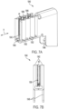
- the second terminal 1040 includes a pair of terminal walls 1042 with one or more curved portions 1052.
- the curved portions 1052 define a plurality of spring retention grooves 1046, which retain the coil springs 44 as discussed above. More specifically, the curved nature of the walls 1042 allow the presence of the retention grooves 1046 while maintaining a constant wall thickness.
- the illustrated walls 1042 may be formed from a single piece sheet material that is pressed or otherwise formed into shape. Indeed, the entire terminal 1040 is configured so that it may be formed from a single piece of formed sheet material.
- FIGS. 8A-B illustrate another embodiment of the second terminal 2040.
- the second terminal 2040 is substantially similar to the second terminal 40 so only the differences will be discussed in detail herein.
- the second terminal 2040 includes a pair of retention grooves 2046 that each form a curvilinear path along the inner surface 2047 of their corresponding wall 2042A, 2042B. More specifically, each retention groove 2046 includes a first portion 2071 that is oriented generally perpendicular to the direction of insertion A (e.g., ⁇ 1%, ⁇ 2%, ⁇ 5%, or ⁇ 10%) and a second portion 2073 that is oriented generally parallel to the direction of insertion A (e.g., ⁇ 1%, ⁇ 2%, ⁇ 5%, or ⁇ 10%). As such, the coil spring 44 positioned within the grooves 2046 also include portions oriented generally perpendicular to and generally parallel to the direction of insertion A (e.g., ⁇ 1%, ⁇ 2%, ⁇ 5%, or ⁇ 10%).
- the coil spring 44 forms a complete loop such that the spring 44 includes a first leg 2075A extending along the retention groove 2046 in the first wall 2042A, a second leg 2075B extending along the retention groove 2046 in the second wall 2042B, and a pair of interconnecting legs 2075C, 2075D extending between the walls 2042A, 2042B and interconnecting the first and second legs 2075A, 2075B.
- the natural elastic nature of the coil 44 e.g., to take on its resting circular shape helps to retain the spring 44 within the grooves 2046 of the terminal 2040.
- separate coil springs 44 may be used to extend along all or a portion of each retention groove 2046 and be retained therein such that no interconnecting portions are required or present.
- FIGS. 9A-C illustrate another embodiment of a terminal 3000.
- the terminal 3000 may be used in place of one or more of the second terminals 40or one of the first terminals 38 of the electrical interface 17.
- the terminal 3000 includes an outer terminal 3060 and an inner terminal 3062 nested within the outer terminal 3060 such that the two terminals 3060, 3062 form a single electrical connection.
- the outer terminal 3060 includes a first pair of legs 3064 and a pair of outer prongs 3066.
- the first pair of legs 3064 are inserted into the circuit board 18 and can be soldered to electrically connect the terminal 3000 to the circuit board 18.
- the outer prongs 3066 are configured to electrically connect and engage a corresponding first connector 36 from the power tool housing 12 to the circuit board 18. As shown in FIG.
- the outer terminal 60 is formed out of a conductive material with a thickness between 0.15 mm and 0.35 mm. In some embodiments, the thickness is between 0.2 mm and 0.3 mm. In some embodiments, the thickness is 0.25 mm.
- the inner terminal 3062 is nested inside the outer terminal 3060 and includes a second pair of legs 3068 and a pair of inner prongs 3070.
- the second pair of legs 3068 are also inserted into the circuit board 18 and are soldered to electrically connect the inner terminal 3062 to the circuit board 18.
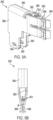
- the pair of inner prongs 3070 have a different shape than the outer prongs 3066. More specifically, the inner prongs 3070 are bent in a V shape and are configured to provide additional contact area for the first connector 36 when fully installed. As shown in FIGS.
- the prongs 3070 first converge together to form a distal end 3067, the prongs then extend back toward the base 3063 where they continue to converge until they form a pinch point 3069. Stated differently, the pinch point 3069 is positioned closer to the base 3063 than the distal end 3065.
- the inner prongs 3070 are configured to limit an insertion depth of the first connector 36. In other embodiments, the inner prongs 3070 are configured to capture or otherwise clamp onto the connector 36. In such alternative embodiments, the clamping force of the inner prongs 3070 may be different than the clamping force exerted by the outer prongs 3066. By doing so, the user will receive tactile feedback to determine how far the connector 36 is inserted. More specifically, the clamping force exerted by the inner prongs 3070 may be greater than that exerted by the outer prongs 3066.
- FIGS. 10A-C illustrate another embodiment of a terminal 4000.
- the terminal 4000 is substantially similar to the terminal 3000 so only the differences will be described in detail herein.
- the terminal 4000 includes an inner terminal 4062 having a pair of inner prongs 4070 bent to be interdigitated. Stated differently, the prongs 4070 are shaped so that they cross-over the midline 4071 of the terminal 4000 so that a prong 4070 originating on one side of the midline 4071 will terminate on the opposite side of the midline 4071.
- the inner prongs 4070 also receive the first connector 36 and increase the contact area between a second terminal 4000 and the first connector 36. In some embodiments, the inner prongs 4070 also limits the insertion depth of the first connector 36.
- FIGS. 11-12 illustrate another embodiment of a terminal 5000.
- the terminal 5000 may replace any one of the second terminals 40 or the first terminals 38 of the electrical interface 17.
- the terminal 5000 is formed from a single piece of sheet material (e.g., metal) and forms a pair of outer prongs 5066, a pair of inner prongs 5070 nested inside the outer prongs 5066, and a mounting portion 5097.
- the outer prongs 5066 are configured to receive and electrically connect a first connector 36 to the circuit board 18, as shown in FIG. 12 .
- the inner prongs 5070 are configured to limit an insertion depth of the first connector 36 into the second terminal 5000.
- the inner prongs 5070 serve as a second clamping point to increase electrical connection surface area and retention strength of the terminal 5000. Since the inner prongs 5070 are nested in the outer prongs 5066, the second terminal 5000 allows for increased contact area without increasing the length of the outer prongs 5066 (e.g., in a direction parallel to the direction of insertion A) or compromising the area of each contact area.
- the mounting portion 5097 electrically connects and supports the second terminal 5000 on a circuit board 18.
- the terminal 5000 is configured so that the outer prongs 5066, the inner prongs 5070, and the mounting portion 5097 may all be formed from a single piece of sheet material by bending and forming that single sheet. More specifically, the outer prongs 5066 have a first or distal end 5081 forming a first clamping or pinch point 5083, and a second end 5085 opposite the first end 5081.
- the inner prongs 5070 originate at the second end 5085 of the outer prongs 5066 whereby a 180 degree fold allows the inner prongs 5070 to extend in generally the same direction as the outer prongs 5066 while being nested within the outer prongs 5066.
- the inner prongs 5070 also include a distal end 5087 forming a second clamping or pinch point 5089, and a second end 5091 opposite the first end 5087.
- the second end 5091 of the inner prongs 5070 and the second end 5085 of the outer prongs 5066 are connected such that the inner and outer prongs 5070, 5066 may be formed by a single monolithic piece of material.
- the connection of the two second ends 5085, 5091 is formed by a 180-degree bend in the monolithic material.
- the terminal 5000 also includes a cross-over or bridge portion 5093 extending between the two outer prongs 5066 and being continuous with both.
- the cross-over is positioned such that it does not interfere with the gap 5050 into which the connector 38 is to be inserted.
- the bridge 5093 is positioned and shaped (e.g., proximate the second ends 5085 of the outer prongs 5066) so that the two individual outer prongs 2066 are connected and therefore can be formed from a single piece of monolithic material. More specifically, the bridge 5093 may include two approximately 90-degree folds on either end thereof to allow the outer prongs 5066 to be placed generally parallel to and spaced a distance from each other.
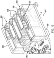
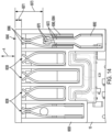
- FIGS. 13-14 illustrate an alternate embodiment of an electrical interface 6017.
- the electrical interface 6017 is substantially similar to the electrical interface 17 described above so only the differences will be described in detail herein.
- the electrical interface 6017 may replace the electrical interface 17 in the battery pack 10.
- the circuit board 6018 includes a plurality of first terminals 6038, a plurality of second terminals 6040, and a terminal separator 6058.
- the first terminals 6038 and the second terminals 6040 are configured so that they may each receive and form different types of electrical connections with different constructions of connectors 36. More specifically, the first terminals 6038 can receive a first connector 6036 from the power tool 12 while the second terminals 6040 can receive a first connector 6036 or a second connector 6037 from the power tool housing 6012 (discussed below).
- each first terminal 6038 may only form a single electrical connection point (e.g., the first terminal 6038 can form a single electrical circuit) while each second terminal 6074 is form one or multiple electrical connection points (e.g., the second terminals 6074 may form two or more independent electrical circuits).
- the first terminals 6038 may form a single electrical connection with both the first connector 6036 and the second connector 6037 while the second terminal 6040 may form a single electrical connection with the first connectors 6036 and form two electrical connections with the second connectors 6040.
- the terminal 6040 includes an outer terminal 6060 and an inner terminal 6062 nested within and electrically isolated from the outer terminal 6060.
- the outer terminal 6060 includes a first pair of legs 6064 soldered to the circuit board 18, and a pair of outer prongs 6066 having a first connection depth 6071.
- the outer terminal 6060 is configured to receive and electrically connect with the first connector 6036 or the second connector 6037 to the circuit board 18.
- the inner terminal 6062 includes a second pair of legs 6068 soldered to a different location on the circuit board 18 than the first pair of legs 6064, and a pair of inner prongs 6070 having a second connection depth 6073 that is different than the first connection depth 6071. More specifically, the second connection depth 6073 is greater than the first connection depth 6071.
- the inner terminal 6062 is configured to only receive and electrically connect to the second connector 6037.
- the second connector 6037 is installed into the second terminal 6040 and both the outer terminal 6060 and inner terminal 6062 engage and form an electrical connection therewith (e.g., see connection point C between the connector 6037 and the outer terminal 6060, and connection point D between the connector 6037 and the inner terminal 6062).
- FIG. 16B shows the first connector 6036 installed in the second terminal 6040 and only forms an electrical connection with the outer terminal 6060 (see connection point E between the outer terminal 6060 and the connector 6036). More specifically, since the first connector 6036 has an insertion length 6039 that is shorter than the insertion length 6041 of the second connector 6037, the first connector 6036 only engages with the outer terminal 6060 of the second terminal 6040.
- the second terminal 6040 includes a shim or insulator 6072 positioned between the inner terminal 6062 and the outer terminal 6060 so that the two terminals remain electrically isolated from each other.
- the shim 72 is made of mica. In other embodiments, the shim 72 could be made from any electrically insulative material.
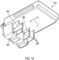
- FIG. 15 illustrates another embodiment of the mounting point 6015 of the power tool 12.
- the mounting point 6015 includes one or more first connectors 6036 having a first insertion length 6039 (e.g., the length of the connector 6036 measured in the direction of insertion A), and one or more second connectors 6037 having a second insertion length 6041 that is different than the first insertion length 6039. More specifically, the second insertion length 6041 is greater than the first insertion length 6039.
- the first connectors 6036 have sufficient insertion length 6039 to form an electrical connection with the outer terminal 6060 of the second terminal 6040 and the first terminal 6038 but to not form an electrical connection with the inner terminal 6062 of the second terminal 6040.
- the second connectors 6037 have a sufficient insertion length 6041 to form an electrical connection with the inner and outer terminals 6062, 6060 of the second terminal 6040 and the first terminal 6038.
- FIGS. 17-19B illustrate another embodiment of an electrical interface 7017.
- the electrical interface 7017 is substantially similar to the electrical interface 6017 so only the differences will be described in detail herein.
- the electrical interface 7017 may replace the electrical interface 17 in the battery pack 10.
- the electrical interface 7017 includes a second terminal 7040 that includes an outer terminal 7060 and an inner terminal 7062.
- the outer terminal 7060 includes a first pair of legs 7064 soldered to the circuit board 18 and a pair of outer prongs 7066.
- the inner terminal 7062 includes a second pair of legs 7068 soldered to the circuit board 18 and a pair of inner prongs 7070.
- the inner terminal 7062 includes an alternate placement of a second pair of legs 7068 to reduce the overall footprint of the second terminal 7040 on the circuit board 18. More specifically, the illustrated outer terminal 7060 defines a length envelope 7061 extending in the direction of insertion A (see FIG. 19A ). The inner terminal 7062 is configured so that the second pair of legs 7068 are completely positioned within the length envelope 7061 of the outer terminal 7060. In still other embodiments, the overall length 7063 of the outer terminal 7060 (measured parallel to the direction of insertion A) is greater than the overall length 7065 of the inner terminal 7062 (measured parallel to the direction of insertion A). In still other embodiments, both the pinch point 7067 of the inner terminal 7062 and the second pair of legs 7068 fall within the length envelope 7061 of the outer terminal 7060.
- the second terminal 7040 is configured to receive the second connector 6037, which is electrically connected to both the outer prongs 7066 and the inner prongs 7070.
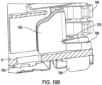
- the illustrated inner prongs 7070 are shown being horizontal in nature such that the base or joint 7069 between the prongs 7070 and the prongs 7070 are offset horizontally from one another (e.g., in a direction parallel to the direction of insertion A) and the joint 7069 itself is oriented perpendicular to the direction of insertion (see FIG. 18 ), it is understood that in other embodiments the prongs 7070 may be vertical in construction. In such an embodiment the joint 7069 and the prongs 7070 are offset vertically (e.g., perpendicular to the direction of insertion A) and the joint itself 7069 is positioned proximate to and extends parallel along the circuit board 18 parallel to the direction of insertion A (see FIG. 18 ). Such a layout allows for shorter leads extending to the legs 7068. The vertical layout also allows the inner prongs 7070 to match the shape of the connector and maximize contact area for a given length of the terminal.
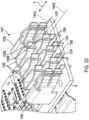
- FIG. 20 and 22A-22B illustrate another embodiment of an electrical interface 11017.
- the electrical interface 11017 is substantially similar to the electrical interface 7017 described above so only the differences will be discussed in detail herein.
- the electrical interface 11017 may replace the electrical interface 17 in the battery pack 10.
- the electrical interface 11017 includes one or more first terminals 11038 and one or more second or stacked terminals 11074.
- Each first terminal 11038 includes a single electrical connection point (e.g., the first terminal 11038 can form a single electrical circuit) while each second terminal 11074 includes multiple electrical connection points (e.g., the second terminals 11074 may form two or more independent electrical circuits). More specifically, the second terminals 11074 include multiple electrical connection points 11039A, 11039B where each electrical connection point 11039A, 11039B may be individually accessed through the corresponding slot 32 in the battery housing 14 without making an electrical connection with the other connection points 11039A, 11039B.
- each connection point 11039A, 11039B defines an insertion axis 11041A, 11041B (extending parallel to the direction of insertion A) that is offset and unique from the insertion axis 11041A, 11041B of all other electrical connection points 11039A, 11039B.
- the terminal 11074 includes two connection points 11039A, 11039B having two insertion axes 11041A, 11041B that are offset at different distances from the underlying circuit board 18.
- the first insertion axis 11041A is spaced a first distance from the circuit board 18 while the second insertion axis 11041B is spaced a second distance from the circuit board 18 that is greater than the first distance.
- the two insertion axes 11041A, 11041B lie on a common plane that is oriented perpendicular to the circuit board 18.
- the second terminal 11074 includes an upper terminal 11082 forming the first electrical connection point 11039A, and a lower terminal 11084 forming the second electrical connection point 11039B that is electrically isolated from the first electrical connection point 11039A.
- the upper terminal 11082 defines the first insertion axis 11041A spaced the first distance from the circuit board 18 while the lower terminal 11084 defines the second insertion axis 11041B spaced the second distance from the circuit board 18 that is less than the first distance.
- the upper terminal 11082 also has a larger insertion distance than the insertion distance of the lower terminal 11084.
- the stacked terminal 11074 receives the split connector 11042, as shown in FIG. 22A (described below), the upper terminal 11082 is configured to receive the upper connector 11078 (see connection G) and the lower terminal 11084 is configured to receive the lower connector 11080 (see connection H). If the stacked terminal 11074 receives the first connector 11036, as shown in FIG. 22B (described below), the lower terminal 11084 receives and electrically connects the first connector 11036 and the upper terminal 11082 is left unconnected (see connection J).
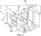
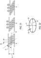
- FIG. 21 illustrates another embodiment of mounting point 11015 of the power tool 12.
- the mounting point 11015 is substantially similar to the mounting point 15 described above so only the differences will be described in detail herein.
- the mounting point 11015 includes one or more split connectors 11042 and one or more first connectors 11036.
- Each split connector 11042 includes a plurality of individual and electrically isolated connection elements 11078, 11080, each extending generally parallel to the direction of insertion A but offset from each other. More specifically, the individual connection elements 11078, 11080 are positioned such that, when the battery 10 is being coupled to the mounting point 11015 of the power tool 12 in the direction of insertion A, each connection element 11078, 11080 will correspond with and be coaxial to a corresponding insertion axis 11041A, 11041B.
- Each connection element 11078, 11080 also has an insertion length that corresponds to the insertion depth of the corresponding terminals 11082, 11084.
- Each first connector 11036 forms a single electrical connection point.
- the first terminals 11038 are configured to receive the first connector 11036 therein.
- the connectors 11036 have a connector height (e.g., perpendicular to the direction of insertion A) that is large enough to overlap both the upper terminal 11082 and the lower terminal 11084 of the split terminal 11074.
- the first connector 11036 may be configured to make an electrical connection with one or both terminals 11082, 11084 of the split terminal 11074 dependent upon its insertion distance.
- the connector may make an electrical connection with both terminals 11082, 11084 simultaneously, however in other embodiments where the insertion distance is greater than the insertion depth of one terminal but less than the insertion depth of the other the first connector 11036 may only make an electrical connection with the shallower of the two terminals.
- FIGS. 23A-B illustrate another embodiment of a circuit board 8018.
- the circuit board 8018 is substantially similar to the circuit board 18 described above so only the difference will be described in detail herein.
- the circuit board 8018 may replace the circuit board 18 in the battery pack 10.
- the circuit board 8018 includes a electrical interface 8017 containing one or more first terminals 8038, one or more second terminals 8040, and a terminal separator 8058.
- the circuit board 8018 also includes an upper PCB cover 8098, and lower PCB cover 8099. A rear of the second terminals 8040 is surrounded by the upper PCB cover 8098.
- the upper PCB cover 8098 is made from a thermal conductive but electrically non-conductive material.
- the upper PCB cover 8098 is configured to dissipate heat generated on the rear end of the second terminal 8040.
- the lower PCB cover 8099 is also made from the same material as the upper PCB cover 8098 and is configured to dissipate heat from a pair of legs 8064 of the second terminal 8040. Additionally, the upper and lower PCB covers 8098, 8099 are manufactured using low pressure over molding.
- FIG. 24A-B illustrate another embodiment of a circuit board 9018.
- the circuit board 9018 includes like components to circuit board 8018 so only the differences will be described in detail herein.
- the upper PCB cover 9098 and a lower PCB cover 9098 are thicker than the upper and lower PCB covers 8098, 8099.
- the additional material on the upper and lower PCB covers 9098, 9099 increase the thermal mass and have greater heat dissipation potential than the upper and lower PCB cover 9098, 9099.
- FIG. 25A illustrates the lower PCB cover 9099
- FIG. 25B illustrates the circuit board 9018 with the lower PCB cover 9099 removed.
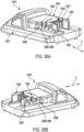
- FIGS. 26A-29 illustrate another embodiment of a battery pack 10010.
- the battery pack 10010 is substantially similar to the battery pack 10 described above so only the differences will be described in detail herein.
- the battery pack 10010 includes a housing 10014, a tool engagement portion 10016, a circuit board 10018, one or more battery cells (not shown), and an electrical interface 10017 in electrical communication with both the circuit board 10018 and the one or more battery cells.
- the tool engagement portion 10016 includes a first spaced apart housing wall or rib 10020 extending parallel the direction of insertion A and a second spaced apart housing wall or rib 10021 also extending parallel to the direction of insertion A.
- the first and second ribs 10020,10021 each define a groove 10022 that also extends parallel to the direction of insertion A.
- the grooves 10022 each include at least one window 10086 open to the internal cavity of the housing 10014 of the battery pack 10010.
- the grooves 10022 are configured to receive a rail 10030 from the power tool 10012 therein when the battery pack 10010 is coupled to the power tool 10012.
- the groove 10022 may be formed into the power tool 12 while the rail 10030 may be positioned on the battery pack 10010.
- the circuit board 100018 of the battery pack 100010 includes a plurality of first terminals 100038 and a plurality of lateral terminals 10088 set at an angle relative to the first terminals 10038. More specifically, each of the first terminals 10038 may be accessed via a slot 10032 formed in the housing 10014 of the battery pack 10010 that is at least partially oriented normal to the direction of insertion A (e.g., the connector is introduced parallel to the direction of insertion A). In contrast, the lateral terminals 10088 are accessible via a window 10086 that is not oriented normal to the direction of insertion A. In the illustrated embodiment, the window 10086 providing access to the lateral terminals 10088 are oriented parallel to the direction of insertion A and completely positioned within one of the two grooves 10022.
- each of the first terminals 10038 are configured to receive a connector 10036 of the power tool 10012. More specifically, each first connector 10036 is configured to be inserted into the terminal 10038 in the direction of insertion A.
- the lateral terminals 10088 are disposed in the windows 10086 of the grooves 10022 and are configured to receive a plurality of lateral connectors 10089 from the power tool 10012.
- the lateral connectors 10089 are configured to come into sliding contact with the lateral terminals 10088 (e.g., slide along the surface of the terminal 10088 that is oriented parallel to the direction of insertion A) whereby a biasing force acting perpendicular to the direction of insertion A presses or otherwise forces the connector 10089 into contact with the terminal 10088.
- the connector 10089 is configured to exert the contacting force (e.g., inwardly toward the terminal 10088) to produce the desired contact but in other embodiments the terminal 10088 may be biased outwardly into engagement with the connector 10089. In still other embodiments, both the connector 10089 and the terminal 10088 may be biased into engagement with each other.
- a positive lateral terminal 10090 of the plurality of lateral terminals 10088 is positioned on the first spaced apart wall 10020 and is soldered to a distinct area of the circuit board 10018.
- the positive lateral terminal 10090 can be operated separately from any of the first terminals 10038.
- a negative lateral terminal 10092 of the plurality of lateral terminal 10088 is positioned on the second spaced apart wall 10021 and is soldered to a first pair of legs 10048 of one of the first terminals 10038.
- the lateral terminal 10088 is connected in parallel to at least one of the first terminals 10038.
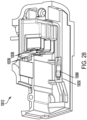
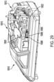
- FIGS. 28 and 29 show that the lateral connectors 10089 are disposed in the rail 10030 of the mounting point 10015 and are configured to engage the lateral terminals 10088 when the battery pack 10010 is fully installed on the power tool 10012.
- the positive lateral terminal 10090 includes a shield 10094 to isolate the lateral terminal 10088 physically and electrically from the first terminals 10038.
- the shield 10094 prevents a short circuit in between the lateral terminals 10088 and the first terminal 10038 and seals the internal cavity of the battery pack 10010 from dust and debris entering through the windows 10086.
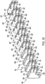
- FIG. 30 shows various alternate embodiments of a terminal 40K-U.
- the second terminals 40K-U may replace any of the previously described terminals.
- the terminal 40K includes a pair of spaced apart terminal walls 42K, a pair of legs 64K, a rear wall 65K, a pair of prongs 66K.
- the spaced apart terminals walls 42K have a greater thickness than the pair of prongs 66K.
- the terminal 40L includes like components to the second terminal 40K, but a pair of prongs 66L and a pair of spaced apart walls 65L, 42L have an equal thickness.
- the terminal 40M includes like components to the terminals 40K, 40L, but the transition between a pair spaced apart terminal walls 42M and a rear wall 65M has a larger radius of curvature than the second terminals 40K, 40L. Additionally, the prongs 66M decrease in thickness as they extend further from the spaced apart terminal walls 42M.
- the terminal 40N includes like components to the terminals 40K-M, but includes a pair of bridged terminal walls 43N instead of spaced apart terminal walls 42K-M.
- the bridged walls 43N also include a through hole 45N on a top surface and does not include the rear wall.
- the terminal 400 includes like components to the second terminal 40N, but a through hole 450 is counterbored.
- the terminal 40P includes like components to the terminals 40N and 400, but a thickness of a pair of bridged terminal walls 43P is larger than the thickness of the corresponding prongs 66P.
- the terminal 40Q includes like components to the terminals 40N-P, but a through hole 45Q includes a curved countersink.
- the terminal 40R includes like components to the terminals 40N-Q, but a through hole 45R includes a countersink.
- the terminal 40S includes like components to the second terminals 40N-R, but does not include the through hole in the bridged wall 43S. However, the terminal 40S includes a rear wall 65S.
- the terminal 40T includes like components to the terminal 40S but includes a rear wall 65T with multiple layers of sheet metal.
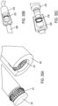
- FIGS. 34A-34C illustrate alternative embodiments of a terminal 40U.
- the terminal 40U is generally formed from a solid piece of metallic material (e.g., copper, aluminum, and the like) and is assembled and/or machined to define a groove 41U therein that is sized to receive a corresponding blade or connector 43U.
- the illustrated terminals 40U are able to accommodate relatively larger current rates.
- the resulting groove 41U may be supplemented with a spring 45U (e.g., a canted spring) positioned therein to help retain the blade 43U therein (see FIG. 34C ).
- the material forming the terminal 40U may be coated such as with gold and the like to reduce current resistance and corrosion.
- FIGS. 35A-35C illustrate alternative embodiments of a terminal 40V, 40W that are generally cylindrical in construction.
- the first terminal 40V includes a series of pivotable conductors 41V movably attached to the terminal 40V for accommodating any variations in size or position between the male connector 43V and the female terminal 40V. While the illustrated construction of FIG. 35A shows both the connector 43V and the terminal 40V having the conductors 41V included therein, it is understood that in other embodiments only one or the other may include such conductors 41V.
- FIG. 35B and 35C illustrate another embodiment where a coiled spring 47W (e.g., a canted spring) is incorporated into one of the terminal 40W or the connector 51W.
- the coiled spring 47W operates as discussed above and is configured to both help retain the connector 51W within the terminal 40W as well as improve the conductivity between the two elements.
Landscapes
- Chemical & Material Sciences (AREA)
- Chemical Kinetics & Catalysis (AREA)
- Electrochemistry (AREA)
- General Chemical & Material Sciences (AREA)
- Life Sciences & Earth Sciences (AREA)
- Engineering & Computer Science (AREA)
- Biophysics (AREA)
- Computer Hardware Design (AREA)
- Battery Mounting, Suspending (AREA)
- Portable Power Tools In General (AREA)
- Coupling Device And Connection With Printed Circuit (AREA)
Abstract
Description
- The present applications claims priority to
U.S. Patent Application No. 63/441,077, filed January 25, 2023 U.S. Patent Application No. 63/486,075, filed February 21, 2023 U.S. Patent Application No. 63/488,659, filed March 6, 2023 - The present disclosure relates to battery pack terminal connections.
- Power tools can receive a battery pack that are also compatible with a number of other power tools and electrical devices. The battery pack includes a tool engagement portion and a circuit board. The tool engagement portion mechanically retains the battery pack to the power tool. The circuit board electrically connects the battery pack to the power tool using a plurality of terminals.
- The disclosure provides, in one aspect, a battery pack for use with a power tool and comprising a housing containing one or more battery cells, a circuit board disposed in the housing, a first terminal, and a second terminal. The circuit board is in electrical communication with one or more battery cells. The first terminal is in electrical communication with the circuit board. The second terminal is also in electrical communication with the circuit board and is constructed differently from the first terminal. The second terminal includes a pair of spaced apart terminal walls, and a coil spring disposed in between the pair of spaced apart walls. The coil spring configured to engage and electrically couple with a portion of the power tool.
- The disclosure provides, in another aspect, a battery pack for use with a power tool and comprising a housing containing one or more battery cells, a circuit board disposed in the housing, and a terminal. The circuit board is in electrical communication with one or more battery cells. The terminal is in electrical communication with the circuit board and is configured to receive and electrically couple to a portion of the power tool. The terminal assembly includes a pair of outer prongs and a pair of inner prongs nested within the outer prongs. Each of the inner prongs have a different shape than the outer prongs.
- The disclosure provides, in another aspect, a battery pack for use with a power tool and comprising a housing containing one or more battery cells, a plurality of terminals, and a plurality of lateral terminals. The housing including a tool engagement portion with a pair of spaced apart housing walls configured to mechanically engage and retain a portion of the power tool. The terminals are disposed between the pair of housing walls. The lateral terminals are configured to conduct electricity through an opening in a respective housing wall of the pair of spaced part housing walls.
- The disclosure provides, in another aspect, a battery pack for use with a power tool having an electric connector. The battery pack including a housing containing one or more battery cells, a first terminal in electrical communication with the battery cells, the first terminal including a pair of spaced apart terminal walls forming a gap therebetween and a coil spring at least partially positioned within the gap. Where the coil spring is configured to selectively engage and form an electrical connection with the electric connector of the power tool when the electric connector is at least partially positioned within the gap.
- Alternatively or additionally, in any combination, where the coil spring is canted.
- Alternatively or additionally, in any combination, where the electric terminal is introduced into the gap in a first insertion direction, and where the coil spring is canted such that it produces a compression direction that is perpendicular to the direction of insertion.
- Alternatively or additionally, in any combination, the battery pack further includes a circuit board disposed in the housing that is in electrical communication with the one or more battery cells and the first terminal.
- Alternatively or additionally, in any combination, where the first terminal includes a pair of legs mounted to the circuit board.
- Alternatively or additionally, in any combination, where at least one terminal wall defines a groove therein, and where the spring is at least partially positioned within the groove.
- Alternatively or additionally, in any combination, where both terminal walls define a groove therein, and where the spring is at least partially positioned in both grooves.
- Alternatively or additionally, in any combination, where the first terminal defines a midplane positioned equidistant from both terminal walls, and where the coil spring is positioned on both sides of the midplane.
- Alternatively or additionally, in any combination, where the coil spring is arranged in a U-shape.
- The disclosure provides, in another aspect, a battery pack for use with a power tool having an electric connector, the battery pack including a housing containing one or more battery cells therein, a terminal in electrical communication with the battery cells, the terminal configured to receive and form an electrical connection with the electrical connector of the power tool, the terminal including a pair of outer prongs, and a pair of inner prongs nested between the pair of outer prongs.
- Alternatively or additionally, in any combination, where the pair of outer prongs have a different shape than the pair of inner prongs.
- Alternatively or additionally, in any combination, where the pair of outer prongs and the pair of inner prongs are both formed from a single piece of monolithic material.
- Alternatively or additionally, in any combination, where the pair of outer prongs and the pair of inner prongs are electrically isolated from each other.
- Alternatively or additionally, in any combination, where the pair of outer prongs has a first insertion depth, where the pair of inner prongs has a second insertion depth, and where the first insertion depth is less than the second insertion depth.
- Alternatively or additionally, in any combination, where the pair of outer prongs define a first insertion axis parallel to a direction of insertion, where the pair of inner prongs define a second insertion axis parallel to a direction of insertion, and where the first insertion axis is not co-axial with the second insertion axis.
- Alternatively or additionally, in any combination, where the pair of outer prongs and the pair of inner prongs are both coupled to a circuit board, where the first insertion axis is spaced a first distance from the circuit board, and where the second insertion axis is spaced a second distance from the circuit board that is greater than the first distance.
- Alternatively or additionally, in any combination, where the pair of outer prongs has a different insertion depth than the pair of inner prongs.
- Alternatively or additionally, in any combination, further comprising a second terminal in electrical communication with the battery cells, and wherein the second terminal is different than the first terminal.
- Alternatively or additionally, in any combination, where the pair of inner prongs are interdigitated.
- The disclosure provides, in another aspect, a battery pack for use with a power tool having an electrical connector, the battery pack including a housing containing one or more battery cells therein, the housing having a tool engagement portion configured to releasably engage the power tool and define a direction of insertion, and a lateral terminal configured to form an electrical connection with the electrical connector of the power tool, where the lateral terminal is accessible through the housing via a window, and where the window is oriented parallel to the direction of insertion.
- Alternatively or additionally, in any combination, where the housing further defines a pair of grooves configured to mechanically engage and retain a portion of the power tool therein, and where the grooves extend parallel to the direction of insertion.
- Alternatively or additionally, in any combination, where the window is positioned in one of the pair of grooves.
- Alternatively or additionally, in any combination, further comprising one more terminals positioned between the pair of grooves.
- Alternatively or additionally, in any combination, further comprising one or more terminals accessible via openings in the housing, and where the openings in the housing are at least partially oriented normal to the axis of insertion.
- Other aspects of the invention will become apparent by consideration of the detailed description and accompanying drawings.
-
-
FIG. 1 illustrates a perspective view of a battery pack. -
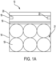
FIG. 1A illustrates an end section view of the battery pack ofFIG. 1 . -
FIG. 2 illustrates a detailed perspective view of a plurality of connectors of a power tool with a portion of a power tool housing cut away. -
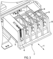
FIG. 3 illustrates a perspective view of a circuit board including a terminal separator. -
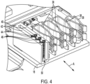
FIG. 4 illustrates a perspective view of the circuit board omitting the terminal separator. -
FIG. 5 illustrates a perspective view of the circuit board engaging the plurality of connectors from the power tool housing. -
FIG. 6A illustrates a perspective view of a second terminal. -
FIG. 6B illustrates a front view of a second terminal ofFIG. 6A . -
FIG. 7A illustrates a perspective view of an alternate embodiment of a second terminal. -
FIG. 7B illustrates a front view of the second terminal ofFIG. 7A . -
FIG. 8A illustrates a perspective view of an alternate embodiment of a second terminal. -
FIG. 8B illustrates a front view of the second terminal ofFIG. 8A . -
FIG. 9A illustrates a perspective view of an alternate embodiment of a second terminal. -
FIG. 9B illustrates a front view of the second terminal ofFIG. 9A receiving the connector from the power tool housing. -
FIG. 9C illustrates a perspective view of an inner terminal of the second terminal ofFIG. 9A . -
FIG. 10A illustrates a perspective view of an alternate embodiment of a second terminal. -
FIG. 10B illustrates a front view of the second terminal ofFIG. 10A receiving the connector from the power tool housing. -
FIG. 10C illustrates a perspective view of an inner terminal of the second terminal ofFIG. 10A . -
FIG. 11 illustrates a perspective view of an alternate embodiment of a second terminal. -
FIG. 12 illustrates a perspective view of the second terminal ofFIG. 11 receiving the connector of the power tool housing. -
FIG. 13 illustrates a perspective view of an alternate embodiment of a circuit board including an alternate embodiment of a second terminal. -
FIG. 14 illustrates a top view of the circuit board and the second terminal ofFIG 13 . -
FIG. 15 illustrates a perspective view of an alternate embodiment of a plurality of connectors of a power tool housing. -
FIG. 16A illustrates an internal view of a first connector of the power tool housing ofFIG. 15 engaged with the second terminal ofFIG. 13 . -
FIG. 16B illustrates an internal view of a second connector of the power tool housing ofFIG. 15 engaged with the second terminal ofFIG. 13 . -
FIG. 17 illustrates a perspective view of an alternate embodiment of a second terminal. -
FIG. 18 illustrates a perspective view of an internal terminal of the second terminal ofFIG. 17 . -
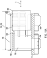
FIG. 19A illustrates a section view of the second terminal ofFIG. 17 receiving a second connector of the power tool housing. -
FIG. 19B illustrates a section view of second terminal ofFIG. 17 engaging a vertical connector of the power tool housing. -
FIG. 20 illustrates a perspective view of an alternate embodiment of a circuit board including an alternate embodiment of a second terminal. -
FIG. 21 illustrates a perspective view of an alternate embodiment of a plurality of second connectors and a plurality of split connectors of a power tool housing. -
FIG. 22A illustrates an internal view of the second terminal ofFIG. 20 engaging a split connector of the power tool housing ofFIG. 21 . -
FIG. 22B illustrates an internal view of the second terminal ofFIG. 20 engaging a second connector of the power tool housing ofFIG. 21 . -
FIG. 23A illustrates a perspective view of an alternate embodiment of a top side of a circuit board. -
FIG. 23B illustrates a perspective view of a bottom side of the circuit board ofFIG. 23A . -
FIG. 24A illustrates a perspective view of an alternate embodiment of a top side of a circuit board. -
FIG. 24B illustrates a perspective view of a bottom side of the circuit board ofFIG. 24A . -
FIG. 25A illustrates a bottom view of the bottom of the circuit board ofFIG. 24A including a bottom PCB cover. -
FIG. 25B illustrates a top view of the bottom of the circuit board ofFIG. 24A omitting the bottom PCB cover. -
FIG. 26A illustrates a perspective view on an alternate embodiment of a battery pack. -
FIG. 26B illustrates another perspective view of the battery pack ofFIG. 26A . -
FIG. 27A illustrates a bottom view of an alternate embodiment of circuit board. -
FIG. 27B illustrates a perspective view of the circuit board ofFIG. 27A and a lateral terminal. -
FIG. 27C illustrates another perspective view of the circuit board ofFIG. 27A and the lateral terminal. -
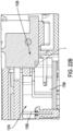
FIG. 28 illustrates a detailed perspective view of an alternate embodiment of connectors of a power tool with a portion of a power tool housing cut away. -
FIG. 29 illustrates a cut-away view of the battery pack engaged with the power tool. -
FIG. 30 illustrates many alternate embodiments of a terminal. -
FIGS. 31 and 32 illustrate a canted coil spring. -
FIG. 33 is a chart showing the deflection of the coil spring ofFIG. 31 relative to the force applied thereto. -
FIGS. 34A-34C illustrate alternative embodiment of a terminal. -
FIGS. 35A-35C illustrate additional alternative embodiments of a terminal. - Before any embodiments of the invention are explained in detail, it is to be understood that the invention is not limited in its application to the details of construction and the arrangement of components set forth in the following description or illustrated in the following drawings. The invention is capable of other embodiments and of being practiced or of being carried out in various ways. Also, it is to be understood that the phraseology and terminology used herein is for the purpose of description and should not be regarded as limiting.
-
FIG. 1 and1A illustrate abattery pack 10 that is configured to be releasably coupled to and form a temporary electrical connection with anelectrical mounting point 15 of apower tool 12 or other electrical device (seeFIG. 2 ).. More specifically, thebattery pack 10 may provide electrical power to various elements of thepower tool 12 including, but not limited to, one or more motors, sensors, LEDs, controllers, pumps, and the like. - The
battery pack 10 includes ahousing 14, atool engagement portion 16, acircuit board 18, one ormore battery cells 19, and anelectrical interface 17 in electrical communication with both thecircuit board 18 and thebattery cells 19. Thehousing 14, in turn, at least partially defines an internal cavity21, which supports thebattery cells 19 and thecircuit board 18 therein. - The
tool engagement portion 16 of thebattery pack 10 is configured to selectively engage the mountingpoint 15 of thepower tool 12. In the illustrated embodiment, thetool engagement portion 16 includes a pair of outer housing walls orribs 20 extending parallel to the direction of insertion A, agroove 22 at least partially formed by theribs 20 and also extending parallel to the direction of insertion A, a pair ofinner housing walls 24 at least partially forming aterminal interface 26, and a pair of actuators or latches 28. Thegroove 22 and theactuators 28 are configured to mechanically engage and retain a correspondingrail 30 of the mountingpoint 15 of thepower tool 12. In other embodiments, thegroove 22 may be formed on thepower tool 12 while therail 30 may be formed on thebattery pack 10. - The
terminal interface 26 includes a plurality ofslots 32 in thehousing 14 each generally corresponding one or more terminals (discussed below) of theelectrical interface 17. Each slot 3, in turn, is sized and shaped to receive one ormore connectors 36 from thepower tool 12 therein. As shown inFIG. 2 , the plurality offirst connectors 36 of thepower tool 12 are disposed on the mountingpoint 15 and generally extend parallel to the direction of insertion A. In the illustrated embodiment, eachconnector 36 is generally formed as a planar plate with a beveled leading edge. - As shown in
FIGS. 3-6B , theelectrical interface 17 includes one or morefirst terminals 38, one or moresecond terminals 40, and aterminal separator 58 to physically and electrically isolate each terminal 38, 40 from one other. When assembled, each terminal 38, 40 is configured to align with an be accessed through acorresponding slot 32 of the terminal interface 26 (seeFIG. 1 ). - The
terminals battery pack 10 are each physically sized and shaped to receive a respective one of thefirst connectors 36 from thepower tool housing 12 therein to form an individual electrical connection therewith. Together, the electrical connections formed between thefirst connectors 36 and theirrespective terminals 36, 40electrically connect thepower tool 12 to thecircuit board 18 and thebatteries 19, as shown inFIG. 5 . - As shown in
FIGS. 6A-B , thesecond terminal 40 is constructed differently than thefirst terminals 38. More specifically, thesecond terminal 40 includes a pair of spaced apartterminal walls 42 forming a terminal gap or opening 50 therebetween, and one or more coil springs 44 at least partially positioned within or open to theterminal gap 50. When assembled, eachcoil spring 44 is in electrical communication with theterminal walls 42 which in turn are in electrical communication with thecircuit board 18 via a pair oflegs 48. - In the illustrated embodiment, the
terminal walls 42 are generally planar and spaced apart a distance such that theterminal gap 50 is sufficiently sized to receive a correspondingfirst connector 36 at least partially therein. Thewalls 42 also each define one or morespring retention grooves 46 formed into theinterior surfaces 47 thereof that are sized and shaped to receive at least a portion of acorresponding coil spring 44 therein. When assembled, theterminal walls 42 andcoil springs 44 are configured such that the coil springs 44 extend inwardly beyond the interior surfaces 47 of thewalls 42 and into thegap 50 so that thecoil distance 49 between opposingsprings 44 is less than the distance between thewalls 42 at the same location. - In some embodiments, one or more of the coil springs 44 of the
second terminal 40 may be configured so that they more readily and consistently deflect when engaged by thefirst connector 36. More specifically, the coil springs 44 may be "canted" so that they apply a near constant force into and against the first connector 36 (e.g., in an inward direction toward the center of the gap 50) as the individual coils of thespring 44 are deflected outwardly to accommodate the presence of theconnector 36 within thegap 50. - In some embodiments, the coil springs 44 are canted in the sense that they are sized and shaped to accommodate compression in a pre-determined compression direction B. More specifically, the geometry of the
coil spring 44 is configured so that, when a force is applied to thespring 44 in the compression direction B thecoil spring 44 exerts a near-constant reaction force when deflected over a working deflection range (seeFIG. 33 ). In the illustrated embodiment, the working deflection range is between 10% and 35% of the restingspring height 61 in the direction of compression B. In other embodiments, the working deflection range is between approximately 10% and approximately 35% (e.g., ±1%, ±2%, ±5%, or ±10%) deflection of the restingspring height 61 in the direction of compression B. In still other embodiments, the force exerted by thecoil spring 44 in the compression direction B varies by between 50% to 58% when deflected over a working deflection range of between 10% to 35% of the restingspring height 61 in the direction of compression B. In still other embodiments, the force exerted by thecoil spring 44 in the compression direction B varies by between 50% to 55% when deflected over a working deflection range of between 10% to 35% deflection of the restingspring height 61 in the compression direction B. In still other embodiments, the force exerted by thecoil spring 44 in the compression direction B varies by between 52% to 58% when deflected over a working deflection range of between 10% to 35% deflection of the restingspring height 61 in the direction of compression B. - In still other embodiments, the coil springs 44 may be canted by modifying various characteristics of the spring's geometry such as the diameter of the
wire 163, thecoil height 165 relative to thecoil width 167, thecoil spacing 169, and the coil angle 171 (seeFIGS. 31 and 32 ). More specifically, the illustrated coil springs 44 are configured such that the coil height 165 (e.g., the coil dimension in the direction of compression B) is less than the coil width 167 (e.g., the coil dimension perpendicular to the direction of compression B; seeFIG. 32 ). Furthermore, the illustrated coil springs 44 are configured so that they have a decreasedcoil angle 171 relative to theaxis 173 of thespring 44. - Compared to the
first terminal 38, thesecond terminals 40 include more individual points of contact with thefirst connector 36 due to the coil spring 44 (e.g., one point of contact for each coil touching the connector 36). More specifically, thesecond terminal 40 has more than four points of contact with aparticular connector 36. In other embodiments, an inner diameter of thecoil spring 44 may be larger to be able to receive or transmit higher current. Theterminal separator 58 is configured to electrically separate thefirst terminals 38 and thesecond terminals 40 to reduce the risk of a short circuit. - In the illustrated embodiment, the
coil spring 44 is shaped such that it forms a substantially "U" shape within the gap 50 (seeFIG. 6B ). More specifically, thespring 44 is positioned so that there is afirst leg 175A extending parallel along afirst wall 42A, asecond leg 175B extending parallel along thesecond wall 42B, and an interconnectingleg 175C extending between the first andsecond legs walls FIG. 6B ). By doing so, the elastic nature of the coil spring 44 (e.g., to remain straight) provides an outward pressure against the twowalls spring 44 in place within theterminal 40. As shown inFIG. 6A , the first andsecond legs retention grooves 46 of thewalls grooves 46 provide lateral support to thespring 44. Specifically, thegrooves 46 help to restrict any motion of thespring 44 along the direction of insertion A when aconnector 36 is being inserted therein. - While the illustrated
spring 44 is U-shaped so that both thefirst leg 175A and thesecond legs 175B are formed as a single piece. It is understood that in other embodiments the first andsecond legs leg 175C does not exist. In such an embodiment, eachleg retention groove 46 mechanically (e.g., via the shape of thegroove 46, the use of tabs, and the like) or through adhesives and the like. In still other embodiments, thespring 44 itself may form a continuous loop such that thesingle spring 44 forms thefirst leg 175A, thesecond leg 175B, the interconnectingleg 175C proximate the bottom of thegap 50, and a second interconnecting leg (not shown) proximate the top of thegap 50. - Once installed in the illustrated U-shaped configuration, the
coil spring 44 may further be oriented so that the direction of compression B of thecoil spring 44, when canted, lies perpendicular to the direction of insertion A for the first andsecond legs spring 44. -
FIGS. 7A-B illustrate another embodiment of thesecond terminal 1040. Thesecond terminal 1040 is substantially similar to thesecond terminal 40 so only the differences will be discussed in detail herein. Thesecond terminal 1040 includes a pair ofterminal walls 1042 with one or morecurved portions 1052. Thecurved portions 1052, in turn, define a plurality ofspring retention grooves 1046, which retain the coil springs 44 as discussed above. More specifically, the curved nature of thewalls 1042 allow the presence of theretention grooves 1046 while maintaining a constant wall thickness. As such, the illustratedwalls 1042 may be formed from a single piece sheet material that is pressed or otherwise formed into shape. Indeed, theentire terminal 1040 is configured so that it may be formed from a single piece of formed sheet material. -
FIGS. 8A-B illustrate another embodiment of thesecond terminal 2040. Thesecond terminal 2040 is substantially similar to thesecond terminal 40 so only the differences will be discussed in detail herein. Thesecond terminal 2040 includes a pair ofretention grooves 2046 that each form a curvilinear path along theinner surface 2047 of theircorresponding wall retention groove 2046 includes afirst portion 2071 that is oriented generally perpendicular to the direction of insertion A (e.g., ±1%, ±2%, ±5%, or ±10%) and asecond portion 2073 that is oriented generally parallel to the direction of insertion A (e.g., ±1%, ±2%, ±5%, or ±10%). As such, thecoil spring 44 positioned within thegrooves 2046 also include portions oriented generally perpendicular to and generally parallel to the direction of insertion A (e.g., ±1%, ±2%, ±5%, or ±10%).. - In the illustrated embodiment, the
coil spring 44 forms a complete loop such that thespring 44 includes afirst leg 2075A extending along theretention groove 2046 in thefirst wall 2042A, asecond leg 2075B extending along theretention groove 2046 in thesecond wall 2042B, and a pair of interconnectinglegs walls second legs spring 44 within thegrooves 2046 of theterminal 2040. In other embodiments,separate coil springs 44 may be used to extend along all or a portion of eachretention groove 2046 and be retained therein such that no interconnecting portions are required or present. -
FIGS. 9A-C illustrate another embodiment of aterminal 3000. The terminal 3000 may be used in place of one or more of the second terminals 40or one of thefirst terminals 38 of theelectrical interface 17. The terminal 3000 includes anouter terminal 3060 and an inner terminal 3062 nested within the outer terminal 3060 such that the twoterminals outer terminal 3060 includes a first pair oflegs 3064 and a pair ofouter prongs 3066. The first pair oflegs 3064 are inserted into thecircuit board 18 and can be soldered to electrically connect the terminal 3000 to thecircuit board 18. Theouter prongs 3066 are configured to electrically connect and engage a correspondingfirst connector 36 from thepower tool housing 12 to thecircuit board 18. As shown inFIG. 9A and 9B , as theouter prongs 3066 extend from thebase 3063 of the terminal 3000, theprongs 3066 first come together to form apinch point 3065, where they then form a forward-splayed shape such that the ends of the prongs extend forward and expand away from each other as they extend away from thecorresponding pinch point 3065. In the illustrated embodiment, the outer terminal 60 is formed out of a conductive material with a thickness between 0.15 mm and 0.35 mm. In some embodiments, the thickness is between 0.2 mm and 0.3 mm. In some embodiments, the thickness is 0.25 mm. - The
inner terminal 3062, shown inFIG. 9C , is nested inside theouter terminal 3060 and includes a second pair oflegs 3068 and a pair ofinner prongs 3070. The second pair oflegs 3068 are also inserted into thecircuit board 18 and are soldered to electrically connect the inner terminal 3062 to thecircuit board 18. The pair ofinner prongs 3070 have a different shape than theouter prongs 3066. More specifically, theinner prongs 3070 are bent in a V shape and are configured to provide additional contact area for thefirst connector 36 when fully installed. As shown inFIGS. 9A and 9B , as theinner prongs 3070 extend from thebase 3063 of the terminal 3000, theprongs 3070 first converge together to form adistal end 3067, the prongs then extend back toward thebase 3063 where they continue to converge until they form apinch point 3069. Stated differently, thepinch point 3069 is positioned closer to thebase 3063 than thedistal end 3065. - In some embodiments, the
inner prongs 3070 are configured to limit an insertion depth of thefirst connector 36. In other embodiments, theinner prongs 3070 are configured to capture or otherwise clamp onto theconnector 36. In such alternative embodiments, the clamping force of theinner prongs 3070 may be different than the clamping force exerted by theouter prongs 3066. By doing so, the user will receive tactile feedback to determine how far theconnector 36 is inserted. More specifically, the clamping force exerted by theinner prongs 3070 may be greater than that exerted by theouter prongs 3066. -
FIGS. 10A-C illustrate another embodiment of aterminal 4000. The terminal 4000 is substantially similar to the terminal 3000 so only the differences will be described in detail herein. The terminal 4000 includes aninner terminal 4062 having a pair ofinner prongs 4070 bent to be interdigitated. Stated differently, theprongs 4070 are shaped so that they cross-over themidline 4071 of the terminal 4000 so that aprong 4070 originating on one side of themidline 4071 will terminate on the opposite side of themidline 4071. Theinner prongs 4070 also receive thefirst connector 36 and increase the contact area between asecond terminal 4000 and thefirst connector 36. In some embodiments, theinner prongs 4070 also limits the insertion depth of thefirst connector 36. -
FIGS. 11-12 illustrate another embodiment of a terminal 5000.. The terminal 5000 may replace any one of thesecond terminals 40 or thefirst terminals 38 of theelectrical interface 17. The terminal 5000 is formed from a single piece of sheet material (e.g., metal) and forms a pair ofouter prongs 5066, a pair ofinner prongs 5070 nested inside theouter prongs 5066, and a mountingportion 5097. Theouter prongs 5066 are configured to receive and electrically connect afirst connector 36 to thecircuit board 18, as shown inFIG. 12 . In some embodiments, theinner prongs 5070 are configured to limit an insertion depth of thefirst connector 36 into thesecond terminal 5000. In other embodiments, theinner prongs 5070 serve as a second clamping point to increase electrical connection surface area and retention strength of theterminal 5000. Since theinner prongs 5070 are nested in theouter prongs 5066, thesecond terminal 5000 allows for increased contact area without increasing the length of the outer prongs 5066 (e.g., in a direction parallel to the direction of insertion A) or compromising the area of each contact area. The mountingportion 5097 electrically connects and supports the second terminal 5000 on acircuit board 18. - As shown in
FIGS. 11 and12 , the terminal 5000 is configured so that theouter prongs 5066, theinner prongs 5070, and the mountingportion 5097 may all be formed from a single piece of sheet material by bending and forming that single sheet. More specifically, theouter prongs 5066 have a first ordistal end 5081 forming a first clamping orpinch point 5083, and asecond end 5085 opposite thefirst end 5081. Theinner prongs 5070 originate at thesecond end 5085 of theouter prongs 5066 whereby a 180 degree fold allows theinner prongs 5070 to extend in generally the same direction as theouter prongs 5066 while being nested within theouter prongs 5066. Stated differently, theinner prongs 5070 also include adistal end 5087 forming a second clamping orpinch point 5089, and asecond end 5091 opposite thefirst end 5087. As shown inFIG. 12 , thesecond end 5091 of theinner prongs 5070 and thesecond end 5085 of theouter prongs 5066 are connected such that the inner andouter prongs second ends - The terminal 5000 also includes a cross-over or
bridge portion 5093 extending between the twoouter prongs 5066 and being continuous with both. The cross-over is positioned such that it does not interfere with the gap 5050 into which theconnector 38 is to be inserted. In the illustrated embodiment, thebridge 5093 is positioned and shaped (e.g., proximate the second ends 5085 of the outer prongs 5066) so that the two individual outer prongs 2066 are connected and therefore can be formed from a single piece of monolithic material. More specifically, thebridge 5093 may include two approximately 90-degree folds on either end thereof to allow theouter prongs 5066 to be placed generally parallel to and spaced a distance from each other. -
FIGS. 13-14 illustrate an alternate embodiment of anelectrical interface 6017. Theelectrical interface 6017 is substantially similar to theelectrical interface 17 described above so only the differences will be described in detail herein. Theelectrical interface 6017 may replace theelectrical interface 17 in thebattery pack 10. The circuit board 6018 includes a plurality offirst terminals 6038, a plurality ofsecond terminals 6040, and aterminal separator 6058. - In the illustrated embodiment, the
first terminals 6038 and thesecond terminals 6040 are configured so that they may each receive and form different types of electrical connections with different constructions ofconnectors 36. More specifically, thefirst terminals 6038 can receive afirst connector 6036 from thepower tool 12 while thesecond terminals 6040 can receive afirst connector 6036 or asecond connector 6037 from the power tool housing 6012 (discussed below). - Furthermore, each first terminal 6038 may only form a single electrical connection point (e.g., the first terminal 6038 can form a single electrical circuit) while each second terminal 6074 is form one or multiple electrical connection points (e.g., the second terminals 6074 may form two or more independent electrical circuits). When docked to the
mounting point 6015, thefirst terminals 6038 may form a single electrical connection with both thefirst connector 6036 and thesecond connector 6037 while the second terminal 6040 may form a single electrical connection with thefirst connectors 6036 and form two electrical connections with thesecond connectors 6040. - The terminal 6040 includes an outer terminal 6060 and an inner terminal 6062 nested within and electrically isolated from the outer terminal 6060. The outer terminal 6060 includes a first pair of legs 6064 soldered to the
circuit board 18, and a pair ofouter prongs 6066 having afirst connection depth 6071. The outer terminal 6060 is configured to receive and electrically connect with thefirst connector 6036 or thesecond connector 6037 to thecircuit board 18. - The
inner terminal 6062 includes a second pair oflegs 6068 soldered to a different location on thecircuit board 18 than the first pair of legs 6064, and a pair ofinner prongs 6070 having asecond connection depth 6073 that is different than thefirst connection depth 6071. More specifically, thesecond connection depth 6073 is greater than thefirst connection depth 6071. Theinner terminal 6062 is configured to only receive and electrically connect to thesecond connector 6037. - As shown in
FIG. 16A , thesecond connector 6037 is installed into thesecond terminal 6040 and both the outer terminal 6060 and inner terminal 6062 engage and form an electrical connection therewith (e.g., see connection point C between theconnector 6037 and the outer terminal 6060, and connection point D between theconnector 6037 and the inner terminal 6062). In contrast,FIG. 16B shows thefirst connector 6036 installed in thesecond terminal 6040 and only forms an electrical connection with the outer terminal 6060 (see connection point E between the outer terminal 6060 and the connector 6036). More specifically, since thefirst connector 6036 has aninsertion length 6039 that is shorter than theinsertion length 6041 of thesecond connector 6037, thefirst connector 6036 only engages with the outer terminal 6060 of thesecond terminal 6040. - As shown in
FIG. 14 , thesecond terminal 6040 includes a shim orinsulator 6072 positioned between theinner terminal 6062 and the outer terminal 6060 so that the two terminals remain electrically isolated from each other. In the illustrated embodiment, the shim 72 is made of mica. In other embodiments, the shim 72 could be made from any electrically insulative material. -
FIG. 15 illustrates another embodiment of themounting point 6015 of thepower tool 12. Themounting point 6015, in turn includes one or morefirst connectors 6036 having a first insertion length 6039 (e.g., the length of theconnector 6036 measured in the direction of insertion A), and one or moresecond connectors 6037 having asecond insertion length 6041 that is different than thefirst insertion length 6039. More specifically, thesecond insertion length 6041 is greater than thefirst insertion length 6039. During use, thefirst connectors 6036 havesufficient insertion length 6039 to form an electrical connection with the outer terminal 6060 of thesecond terminal 6040 and the first terminal 6038 but to not form an electrical connection with theinner terminal 6062 of thesecond terminal 6040. In contrast, thesecond connectors 6037 have asufficient insertion length 6041 to form an electrical connection with the inner andouter terminals 6062, 6060 of thesecond terminal 6040 and thefirst terminal 6038. -
FIGS. 17-19B illustrate another embodiment of anelectrical interface 7017. Theelectrical interface 7017 is substantially similar to theelectrical interface 6017 so only the differences will be described in detail herein. Theelectrical interface 7017 may replace theelectrical interface 17 in thebattery pack 10. Theelectrical interface 7017 includes a second terminal 7040 that includes anouter terminal 7060 and aninner terminal 7062. Theouter terminal 7060 includes a first pair oflegs 7064 soldered to thecircuit board 18 and a pair ofouter prongs 7066. As shown inFIGS. 18 and19 , theinner terminal 7062 includes a second pair oflegs 7068 soldered to thecircuit board 18 and a pair ofinner prongs 7070. - Compared to the
outer terminal 7060, theinner terminal 7062 includes an alternate placement of a second pair oflegs 7068 to reduce the overall footprint of the second terminal 7040 on thecircuit board 18. More specifically, the illustratedouter terminal 7060 defines a length envelope 7061 extending in the direction of insertion A (seeFIG. 19A ). Theinner terminal 7062 is configured so that the second pair oflegs 7068 are completely positioned within the length envelope 7061 of theouter terminal 7060. In still other embodiments, the overall length 7063 of the outer terminal 7060 (measured parallel to the direction of insertion A) is greater than theoverall length 7065 of the inner terminal 7062 (measured parallel to the direction of insertion A). In still other embodiments, both thepinch point 7067 of theinner terminal 7062 and the second pair oflegs 7068 fall within the length envelope 7061 of theouter terminal 7060. - As shown in
FIG. 19A , thesecond terminal 7040 is configured to receive thesecond connector 6037, which is electrically connected to both theouter prongs 7066 and theinner prongs 7070. - While the illustrated
inner prongs 7070 are shown being horizontal in nature such that the base or joint 7069 between theprongs 7070 and theprongs 7070 are offset horizontally from one another (e.g., in a direction parallel to the direction of insertion A) and the joint 7069 itself is oriented perpendicular to the direction of insertion (seeFIG. 18 ), it is understood that in other embodiments theprongs 7070 may be vertical in construction. In such an embodiment the joint 7069 and theprongs 7070 are offset vertically (e.g., perpendicular to the direction of insertion A) and the joint itself 7069 is positioned proximate to and extends parallel along thecircuit board 18 parallel to the direction of insertion A (seeFIG. 18 ). Such a layout allows for shorter leads extending to thelegs 7068. The vertical layout also allows theinner prongs 7070 to match the shape of the connector and maximize contact area for a given length of the terminal. -
FIG. 20 and22A-22B illustrate another embodiment of anelectrical interface 11017. Theelectrical interface 11017 is substantially similar to theelectrical interface 7017 described above so only the differences will be discussed in detail herein. Theelectrical interface 11017 may replace theelectrical interface 17 in thebattery pack 10. Theelectrical interface 11017 includes one or morefirst terminals 11038 and one or more second or stackedterminals 11074. - Each
first terminal 11038 includes a single electrical connection point (e.g., thefirst terminal 11038 can form a single electrical circuit) while eachsecond terminal 11074 includes multiple electrical connection points (e.g., thesecond terminals 11074 may form two or more independent electrical circuits). More specifically, thesecond terminals 11074 include multiple electrical connection points 11039A, 11039B where eachelectrical connection point slot 32 in thebattery housing 14 without making an electrical connection with the other connection points 11039A, 11039B. More specifically, eachconnection point insertion axis insertion axis terminal 11074 includes twoconnection points insertion axes underlying circuit board 18. Stated differently, thefirst insertion axis 11041A is spaced a first distance from thecircuit board 18 while thesecond insertion axis 11041B is spaced a second distance from thecircuit board 18 that is greater than the first distance. Furthermore, in the illustrated embodiment the twoinsertion axes circuit board 18. - The
second terminal 11074 includes anupper terminal 11082 forming the firstelectrical connection point 11039A, and alower terminal 11084 forming the secondelectrical connection point 11039B that is electrically isolated from the firstelectrical connection point 11039A. As shown inFIG. 20 , theupper terminal 11082 defines thefirst insertion axis 11041A spaced the first distance from thecircuit board 18 while thelower terminal 11084 defines thesecond insertion axis 11041B spaced the second distance from thecircuit board 18 that is less than the first distance. Furthermore, theupper terminal 11082 also has a larger insertion distance than the insertion distance of thelower terminal 11084. - During use, if the
stacked terminal 11074 receives thesplit connector 11042, as shown inFIG. 22A (described below), theupper terminal 11082 is configured to receive the upper connector 11078 (see connection G) and thelower terminal 11084 is configured to receive the lower connector 11080 (see connection H). If thestacked terminal 11074 receives thefirst connector 11036, as shown inFIG. 22B (described below), thelower terminal 11084 receives and electrically connects thefirst connector 11036 and theupper terminal 11082 is left unconnected (see connection J). -
FIG. 21 illustrates another embodiment of mountingpoint 11015 of thepower tool 12. The mountingpoint 11015 is substantially similar to the mountingpoint 15 described above so only the differences will be described in detail herein. The mountingpoint 11015 includes one ormore split connectors 11042 and one or morefirst connectors 11036. Eachsplit connector 11042 includes a plurality of individual and electricallyisolated connection elements individual connection elements battery 10 is being coupled to themounting point 11015 of thepower tool 12 in the direction of insertion A, eachconnection element corresponding insertion axis connection element corresponding terminals - Each
first connector 11036 forms a single electrical connection point. During use, thefirst terminals 11038 are configured to receive thefirst connector 11036 therein. In some embodiments, theconnectors 11036 have a connector height (e.g., perpendicular to the direction of insertion A) that is large enough to overlap both theupper terminal 11082 and thelower terminal 11084 of thesplit terminal 11074. As such, thefirst connector 11036 may be configured to make an electrical connection with one or bothterminals split terminal 11074 dependent upon its insertion distance. In such embodiments, where the insertion distance of any oneconnector 11036 exceeds the insertion lengths of bothterminals terminals first connector 11036 may only make an electrical connection with the shallower of the two terminals. -
FIGS. 23A-B illustrate another embodiment of acircuit board 8018. Thecircuit board 8018 is substantially similar to thecircuit board 18 described above so only the difference will be described in detail herein. Thecircuit board 8018 may replace thecircuit board 18 in thebattery pack 10. Thecircuit board 8018 includes aelectrical interface 8017 containing one or morefirst terminals 8038, one or moresecond terminals 8040, and aterminal separator 8058. Thecircuit board 8018 also includes anupper PCB cover 8098, andlower PCB cover 8099. A rear of thesecond terminals 8040 is surrounded by theupper PCB cover 8098. Theupper PCB cover 8098 is made from a thermal conductive but electrically non-conductive material. Theupper PCB cover 8098 is configured to dissipate heat generated on the rear end of thesecond terminal 8040. Thelower PCB cover 8099 is also made from the same material as theupper PCB cover 8098 and is configured to dissipate heat from a pair of legs 8064 of thesecond terminal 8040. Additionally, the upper and lower PCB covers 8098, 8099 are manufactured using low pressure over molding. -
FIG. 24A-B illustrate another embodiment of acircuit board 9018. Thecircuit board 9018 includes like components tocircuit board 8018 so only the differences will be described in detail herein. Theupper PCB cover 9098 and alower PCB cover 9098 are thicker than the upper and lower PCB covers 8098, 8099. The additional material on the upper and lower PCB covers 9098, 9099 increase the thermal mass and have greater heat dissipation potential than the upper andlower PCB cover FIG. 25A illustrates thelower PCB cover 9099, whileFIG. 25B illustrates thecircuit board 9018 with thelower PCB cover 9099 removed. -
FIGS. 26A-29 illustrate another embodiment of abattery pack 10010. Thebattery pack 10010 is substantially similar to thebattery pack 10 described above so only the differences will be described in detail herein. As shown inFIGS. 26A-B , thebattery pack 10010 includes ahousing 10014, atool engagement portion 10016, acircuit board 10018, one or more battery cells (not shown), and anelectrical interface 10017 in electrical communication with both thecircuit board 10018 and the one or more battery cells. Thetool engagement portion 10016 includes a first spaced apart housing wall orrib 10020 extending parallel the direction of insertion A and a second spaced apart housing wall orrib 10021 also extending parallel to the direction of insertion A. The first andsecond ribs groove 10022 that also extends parallel to the direction of insertion A. Thegrooves 10022, in turn, each include at least onewindow 10086 open to the internal cavity of thehousing 10014 of thebattery pack 10010. During use, thegrooves 10022 are configured to receive arail 10030 from thepower tool 10012 therein when thebattery pack 10010 is coupled to thepower tool 10012. In other embodiments, thegroove 10022 may be formed into thepower tool 12 while therail 10030 may be positioned on thebattery pack 10010. - As shown in
FIGS. 27A-C , the circuit board 100018 of the battery pack 100010 includes a plurality of first terminals 100038 and a plurality of lateral terminals 10088 set at an angle relative to thefirst terminals 10038. More specifically, each of thefirst terminals 10038 may be accessed via aslot 10032 formed in thehousing 10014 of thebattery pack 10010 that is at least partially oriented normal to the direction of insertion A (e.g., the connector is introduced parallel to the direction of insertion A). In contrast, the lateral terminals 10088 are accessible via awindow 10086 that is not oriented normal to the direction of insertion A. In the illustrated embodiment, thewindow 10086 providing access to the lateral terminals 10088 are oriented parallel to the direction of insertion A and completely positioned within one of the twogrooves 10022. - During use, each of the
first terminals 10038 are configured to receive aconnector 10036 of thepower tool 10012. More specifically, eachfirst connector 10036 is configured to be inserted into the terminal 10038 in the direction of insertion A. In contrast, the lateral terminals 10088 are disposed in thewindows 10086 of thegrooves 10022 and are configured to receive a plurality oflateral connectors 10089 from thepower tool 10012. During use, thelateral connectors 10089 are configured to come into sliding contact with the lateral terminals 10088 (e.g., slide along the surface of the terminal 10088 that is oriented parallel to the direction of insertion A) whereby a biasing force acting perpendicular to the direction of insertion A presses or otherwise forces theconnector 10089 into contact with the terminal 10088. In the illustrated embodiment, theconnector 10089 is configured to exert the contacting force (e.g., inwardly toward the terminal 10088) to produce the desired contact but in other embodiments the terminal 10088 may be biased outwardly into engagement with theconnector 10089. In still other embodiments, both theconnector 10089 and the terminal 10088 may be biased into engagement with each other. - As shown in
FIGS. 26A and27B , a positive lateral terminal 10090 of the plurality of lateral terminals 10088 is positioned on the first spaced apartwall 10020 and is soldered to a distinct area of thecircuit board 10018. In this configuration, the positive lateral terminal 10090 can be operated separately from any of thefirst terminals 10038. As shown inFIG. 26B and27C , a negative lateral terminal 10092 of the plurality of lateral terminal 10088 is positioned on the second spaced apartwall 10021 and is soldered to a first pair oflegs 10048 of one of thefirst terminals 10038. In this configuration, the lateral terminal 10088 is connected in parallel to at least one of thefirst terminals 10038. -
FIGS. 28 and29 show that thelateral connectors 10089 are disposed in therail 10030 of the mountingpoint 10015 and are configured to engage the lateral terminals 10088 when thebattery pack 10010 is fully installed on thepower tool 10012. - As shown in
FIG. 27B , the positive lateral terminal 10090 includes ashield 10094 to isolate the lateral terminal 10088 physically and electrically from thefirst terminals 10038. Theshield 10094 prevents a short circuit in between the lateral terminals 10088 and thefirst terminal 10038 and seals the internal cavity of thebattery pack 10010 from dust and debris entering through thewindows 10086. -
FIG. 30 shows various alternate embodiments of a terminal 40K-U. Thesecond terminals 40K-U may replace any of the previously described terminals. The terminal 40K includes a pair of spaced apartterminal walls 42K, a pair oflegs 64K, arear wall 65K, a pair ofprongs 66K. The spaced apartterminals walls 42K have a greater thickness than the pair ofprongs 66K. The terminal 40L includes like components to thesecond terminal 40K, but a pair ofprongs 66L and a pair of spaced apartwalls terminals terminal walls 42M and arear wall 65M has a larger radius of curvature than thesecond terminals prongs 66M decrease in thickness as they extend further from the spaced apartterminal walls 42M. The terminal 40N includes like components to theterminals 40K-M, but includes a pair of bridgedterminal walls 43N instead of spaced apartterminal walls 42K-M. The bridgedwalls 43N also include a throughhole 45N on a top surface and does not include the rear wall. The terminal 400 includes like components to the second terminal 40N, but a throughhole 450 is counterbored. The terminal 40P includes like components to theterminals terminal walls 43P is larger than the thickness of the correspondingprongs 66P. The terminal 40Q includes like components to theterminals 40N-P, but a throughhole 45Q includes a curved countersink. The terminal 40R includes like components to theterminals 40N-Q, but a throughhole 45R includes a countersink. The terminal 40S includes like components to thesecond terminals 40N-R, but does not include the through hole in the bridgedwall 43S. However, the terminal 40S includes arear wall 65S. The terminal 40T includes like components to the terminal 40S but includes arear wall 65T with multiple layers of sheet metal. -
FIGS. 34A-34C illustrate alternative embodiments of a terminal 40U. More specifically, the terminal 40U is generally formed from a solid piece of metallic material (e.g., copper, aluminum, and the like) and is assembled and/or machined to define agroove 41U therein that is sized to receive a corresponding blade orconnector 43U. By being formed of solid materials instead of sheet materials (e.g., metals) the illustratedterminals 40U are able to accommodate relatively larger current rates. As shown, the resultinggroove 41U may be supplemented with a spring 45U (e.g., a canted spring) positioned therein to help retain theblade 43U therein (seeFIG. 34C ). In still other embodiments, the material forming the terminal 40U may be coated such as with gold and the like to reduce current resistance and corrosion. -
FIGS. 35A-35C illustrate alternative embodiments of a terminal 40V, 40W that are generally cylindrical in construction. Thefirst terminal 40V includes a series ofpivotable conductors 41V movably attached to the terminal 40V for accommodating any variations in size or position between themale connector 43V and thefemale terminal 40V. While the illustrated construction ofFIG. 35A shows both theconnector 43V and the terminal 40V having theconductors 41V included therein, it is understood that in other embodiments only one or the other may includesuch conductors 41V. -
FIG. 35B and 35C illustrate another embodiment where acoiled spring 47W (e.g., a canted spring) is incorporated into one of the terminal 40W or theconnector 51W. Thecoiled spring 47W operates as discussed above and is configured to both help retain theconnector 51W within the terminal 40W as well as improve the conductivity between the two elements. - When used in this specification and claims, the terms "comprises" and "comprising" and variations thereof mean that the specified features, steps or integers are included. The terms are not to be interpreted to exclude the presence of other features, steps or components.
- Various features and advantages of the invention are set forth in the following claims.
- Representative features are set out in the following clauses, which stand alone or may be combined, in any combination, with one or more features disclosed in the text and/or drawings of the specification.
- 1. A battery pack for use with a power tool having an electric connector, the battery pack comprising:
- a housing containing one or more battery cells;
- a first terminal in electrical communication with the battery cells, the first terminal including a pair of spaced apart terminal walls forming a gap therebetween and a coil spring at least partially positioned within the gap, wherein the coil spring is configured to selectively engage and form an electrical connection with the electric connector of the power tool when the electric connector is at least partially positioned within the gap.
- 2. The battery pack of clause 1, wherein the coil spring is canted.
- 3. The battery pack of clause 1, wherein the electric terminal is introduced into the gap in a first insertion direction, and wherein the coil spring is canted such that it produces a compression direction that is perpendicular to the direction of insertion.
- 4. The battery pack of clause 1, wherein the battery pack further includes a circuit board disposed in the housing that is in electrical communication with the one or more battery cells and the first terminal.
- 5. The battery pack of clause 4, wherein the first terminal includes a pair of legs mounted to the circuit board.
- 6. The battery pack of clause 1, wherein at least one terminal wall defines a groove therein, and wherein the spring is at least partially positioned within the groove.
- 7. The battery pack of clause 6, wherein both terminal walls define a groove therein, and wherein the spring is at least partially positioned in both grooves.
- 8. The battery pack of clause 1, wherein the first terminal defines a midplane positioned equidistant from both terminal walls, and wherein the coil spring is positioned on both sides of the midplane.
- 9. The battery pack of clause 1, wherein the coil spring is arranged in a U-shape.
- 10. A battery pack for use with a power tool having an electric connector, the battery pack comprising:
- a housing containing one or more battery cells therein;
- a terminal in electrical communication with the battery cells, the terminal configured to receive and form an electrical connection with the electrical connector of the power tool, the terminal including:
- a pair of outer prongs, and
- a pair of inner prongs nested between the pair of outer prongs.
- 11. The battery pack of
clause 10, wherein the pair of outer prongs have a different shape than the pair of inner prongs. - 12. The battery pack of
clause 10, wherein the pair of outer prongs and the pair of inner prongs are both formed from a single piece of monolithic material.. - 13. The battery pack of
clause 10, wherein the pair of outer prongs and the pair of inner prongs are electrically isolated from each other. - 14. The battery pack of
clause 10, wherein the pair of outer prongs has a first insertion depth, wherein the pair of inner prongs has a second insertion depth, and wherein the first insertion depth is less than the second insertion depth. - 15. The battery pack of
clause 10, wherein the pair of outer prongs define a first insertion axis parallel to a direction of insertion, wherein the pair of inner prongs define a second insertion axis parallel to a direction of insertion, and wherein the first insertion axis is not co-axial with the second insertion axis. - 16. The battery pack of
clause 15, wherein the pair of outer prongs and the pair of inner prongs are both coupled to a circuit board, wherein the first insertion axis is spaced a first distance from the circuit board, and wherein the second insertion axis is spaced a second distance from the circuit board that is greater than the first distance. - 17. The battery pack of
clause 15, wherein the pair of outer prongs has a different insertion depth than the pair of inner prongs. - 18. The battery pack of
clause 10, further comprising a second terminal in electrical communication with the battery cells, and wherein the second terminal is different than the first terminal. - 19. The battery pack of
clause 10, wherein the pair of inner prongs are interdigitated. - 20. A battery pack for use with a power tool having an electrical connector, the battery pack comprising:
- a housing containing one or more battery cells therein, the housing having a tool engagement portion configured to releasably engage the power tool and define a direction of insertion; and
- a lateral terminal configured to form an electrical connection with the electrical connector of the power tool, wherein the lateral terminal is accessible through the housing via a window, and wherein the window is oriented parallel to the direction of insertion.
- 21. The battery pack of
clause 20, wherein the housing further defines a pair of grooves configured to mechanically engage and retain a portion of the power tool therein, wherein the grooves extend parallel to the direction of insertion. - 22. The battery pack of
clause 21, wherein the window is positioned in one of the pair of grooves. - 23. The battery pack of
clause 21, further comprising one more terminals positioned between the pair of grooves. - 24. The battery pack of
clause 20, further comprising one or more terminals accessible via openings in the housing, and wherein the openings in the housing are at least partially oriented normal to the axis of insertion.
Claims (15)
- A battery pack for use with a power tool having an electric connector, the battery pack comprising:a housing containing one or more battery cells therein;a terminal in electrical communication with the battery cells, the terminal configured to receive and form an electrical connection with the electrical connector of the power tool, the terminal including:a pair of outer prongs, anda pair of inner prongs nested between the pair of outer prongs.
- The battery pack of claim 1,wherein the pair of outer prongs have a different shape than the pair of inner prongs, and/orwherein the pair of outer prongs and the pair of inner prongs are both formed from a single piece of monolithic material, and/orwherein the pair of outer prongs and the pair of inner prongs are electrically isolated from each other.
- The battery pack of claim 1 or 2,wherein the pair of outer prongs has a first insertion depth, wherein the pair of inner prongs has a second insertion depth, and wherein the first insertion depth is less than the second insertion depth, and/orwherein the pair of outer prongs define a first insertion axis parallel to a direction of insertion, wherein the pair of inner prongs define a second insertion axis parallel to a direction of insertion, and wherein the first insertion axis is not co-axial with the second insertion axis.
- The battery pack of claim 3,wherein the pair of outer prongs and the pair of inner prongs are both coupled to a circuit board, wherein the first insertion axis is spaced a first distance from the circuit board, and wherein the second insertion axis is spaced a second distance from the circuit board that is greater than the first distance,and/or wherein the pair of outer prongs has a different insertion depth than the pair of inner prongs.
- The battery pack of any one of claims 1 to 4,
further comprising a second terminal in electrical communication with the battery cells, and wherein the second terminal is different than the first terminal. - The battery pack of any one of claims 1 to 5, wherein the pair of inner prongs are interdigitated.
- A battery pack for use with a power tool having an electric connector, the battery pack comprising:a housing containing one or more battery cells;a first terminal in electrical communication with the battery cells, the first terminal including a pair of spaced apart terminal walls forming a gap therebetween and a coil spring at least partially positioned within the gap, wherein the coil spring is configured to selectively engage and form an electrical connection with the electric connector of the power tool when the electric connector is at least partially positioned within the gap.
- The battery pack of claim 7,
wherein the coil spring is canted, and/or
wherein the electric terminal is introduced into the gap in a first insertion direction, and wherein the coil spring is canted such that it produces a compression direction that is perpendicular to the direction of insertion. - The battery pack of claim 7 or 8, wherein the battery pack further includes a circuit board disposed in the housing that is in electrical communication with the one or more battery cells and the first terminal,
preferably wherein the first terminal includes a pair of legs mounted to the circuit board. - The battery pack of any one of claims 7 to 9, wherein at least one terminal wall defines a groove therein, and wherein the spring is at least partially positioned within the groove,
preferably wherein both terminal walls define a groove therein, and wherein the spring is at least partially positioned in both grooves. - The battery pack of any one of claims 7 to 10,wherein the first terminal defines a midplane positioned equidistant from both terminal walls, and wherein the coil spring is positioned on both sides of the midplane, and/orwherein the coil spring is arranged in a U-shape.
- A battery pack for use with a power tool having an electrical connector, the battery pack comprising:a housing containing one or more battery cells therein, the housing having a tool engagement portion configured to releasably engage the power tool and define a direction of insertion; anda lateral terminal configured to form an electrical connection with the electrical connector of the power tool, wherein the lateral terminal is accessible through the housing via a window, and wherein the window is oriented parallel to the direction of insertion.
- The battery pack of claim 12, wherein the housing further defines a pair of grooves configured to mechanically engage and retain a portion of the power tool therein, wherein the grooves extend parallel to the direction of insertion.
- The battery pack of claim 13, wherein the window is positioned in one of the pair of grooves and/or further comprising one more terminals positioned between the pair of grooves.
- The battery pack of any one of claims 12 to 14, further comprising one or more terminals accessible via openings in the housing, and wherein the openings in the housing are at least partially oriented normal to the axis of insertion.
Applications Claiming Priority (3)
| Application Number | Priority Date | Filing Date | Title |
|---|---|---|---|
| US202363441077P | 2023-01-25 | 2023-01-25 | |
| US202363486075P | 2023-02-21 | 2023-02-21 | |
| US202363488659P | 2023-03-06 | 2023-03-06 |
Publications (2)
| Publication Number | Publication Date |
|---|---|
| EP4407766A2 true EP4407766A2 (en) | 2024-07-31 |
| EP4407766A3 EP4407766A3 (en) | 2025-03-05 |
Family
ID=89722974
Family Applications (1)
| Application Number | Title | Priority Date | Filing Date |
|---|---|---|---|
| EP24153932.9A Pending EP4407766A3 (en) | 2023-01-25 | 2024-01-25 | Battery pack terminal |
Country Status (4)
| Country | Link |
|---|---|
| US (1) | US20240250375A1 (en) |
| EP (1) | EP4407766A3 (en) |
| JP (1) | JP7824015B2 (en) |
| CN (1) | CN222233795U (en) |
Family Cites Families (12)
| Publication number | Priority date | Publication date | Assignee | Title |
|---|---|---|---|---|
| US4810213A (en) * | 1975-01-30 | 1989-03-07 | Square D Company | Low resistance electrical connecting assembly |
| JPH043410Y2 (en) * | 1984-10-03 | 1992-02-03 | ||
| JPH0377285A (en) * | 1989-08-19 | 1991-04-02 | Fujitsu Ltd | Female contact |
| KR101124015B1 (en) * | 2003-07-16 | 2012-03-26 | 그리픽스, 인코포레이티드 | Electrical interconnect assembly with interlocking contact system |
| JP4449988B2 (en) * | 2007-02-16 | 2010-04-14 | 三菱電機株式会社 | Contact device |
| DE202010010827U1 (en) * | 2010-07-29 | 2010-10-21 | Rosenberger Hochfrequenztechnik Gmbh & Co. Kg | High Power Connectors |
| DE202011003555U1 (en) * | 2011-03-04 | 2011-05-26 | ROSENBERGER Hochfrequenztechnik GmbH & Co. KG, 83413 | High current connector with ring spring contact |
| JP6926770B2 (en) * | 2017-07-21 | 2021-08-25 | 工機ホールディングス株式会社 | Battery packs and electrical equipment using battery packs |
| CN118249047A (en) * | 2018-11-27 | 2024-06-25 | 格力博(江苏)股份有限公司 | Battery pack and power tool system |
| CN112072059A (en) * | 2019-06-11 | 2020-12-11 | 南京德朔实业有限公司 | Battery pack, combination of battery pack and electric tool |
| KR102806172B1 (en) * | 2020-06-01 | 2025-05-13 | 주식회사 엘지에너지솔루션 | Battery pack with clip-type connector |
| CN113782908B (en) * | 2020-06-10 | 2024-01-19 | 南京泉峰科技有限公司 | Battery pack |
-
2024
- 2024-01-24 US US18/421,232 patent/US20240250375A1/en active Pending
- 2024-01-24 JP JP2024008686A patent/JP7824015B2/en active Active
- 2024-01-25 EP EP24153932.9A patent/EP4407766A3/en active Pending
- 2024-01-25 CN CN202420192688.7U patent/CN222233795U/en active Active
Also Published As
| Publication number | Publication date |
|---|---|
| JP2024116078A (en) | 2024-08-27 |
| CN222233795U (en) | 2024-12-24 |
| US20240250375A1 (en) | 2024-07-25 |
| EP4407766A3 (en) | 2025-03-05 |
| JP7824015B2 (en) | 2026-03-04 |
Similar Documents
| Publication | Publication Date | Title |
|---|---|---|
| KR100238930B1 (en) | Pluggable modular splicing connectors and bridging adapters | |
| CN1188933C (en) | Premold with covered crimp | |
| JP4565968B2 (en) | Pack battery | |
| JPH0227673A (en) | Modular jack connection block | |
| EP4038698A1 (en) | Couplers for single pair connectors | |
| US8944836B2 (en) | Wire line connector | |
| KR20060012318A (en) | Receptacle Electrical Terminals | |
| EP4407766A2 (en) | Battery pack terminal | |
| CN218731886U (en) | Sheet type contact element jack structure | |
| CN215732583U (en) | a socket converter | |
| KR101643218B1 (en) | Terminal for connector and connector having the same | |
| CN2520031Y (en) | Connector assembly | |
| CN214898904U (en) | Terminal block structure for easy wiring | |
| CN211789576U (en) | Contact spring piece and plug | |
| CN112038805A (en) | Elbow straight connector jack | |
| CN219018771U (en) | Photovoltaic connector and photovoltaic junction box | |
| CN207116749U (en) | Connector | |
| CN214849440U (en) | Adapters and Rail Sockets | |
| TWI233247B (en) | Multi-pole connector for coaxial cable | |
| EP4393035A1 (en) | Single-pair ethernet connector jack | |
| CN211351039U (en) | wire connector | |
| KR20210108308A (en) | Connector | |
| CN116111395B (en) | A type of ultra-thin power strip | |
| CN224123549U (en) | power outlet | |
| CN216161942U (en) | an electrical connector |
Legal Events
| Date | Code | Title | Description |
|---|---|---|---|
| PUAI | Public reference made under article 153(3) epc to a published international application that has entered the european phase |
Free format text: ORIGINAL CODE: 0009012 |
|
| STAA | Information on the status of an ep patent application or granted ep patent |
Free format text: STATUS: REQUEST FOR EXAMINATION WAS MADE |
|
| 17P | Request for examination filed |
Effective date: 20240125 |
|
| AK | Designated contracting states |
Kind code of ref document: A2 Designated state(s): AL AT BE BG CH CY CZ DE DK EE ES FI FR GB GR HR HU IE IS IT LI LT LU LV MC ME MK MT NL NO PL PT RO RS SE SI SK SM TR |
|
| RIC1 | Information provided on ipc code assigned before grant |
Ipc: H01M 50/296 20210101ALI20241031BHEP Ipc: H01M 50/247 20210101ALI20241031BHEP Ipc: H01M 50/204 20210101AFI20241031BHEP |
|
| PUAL | Search report despatched |
Free format text: ORIGINAL CODE: 0009013 |
|
| AK | Designated contracting states |
Kind code of ref document: A3 Designated state(s): AL AT BE BG CH CY CZ DE DK EE ES FI FR GB GR HR HU IE IS IT LI LT LU LV MC ME MK MT NL NO PL PT RO RS SE SI SK SM TR |
|
| RIC1 | Information provided on ipc code assigned before grant |
Ipc: H01M 50/296 20210101ALI20250124BHEP Ipc: H01M 50/247 20210101ALI20250124BHEP Ipc: H01M 50/204 20210101AFI20250124BHEP |