EP4407759A1 - Casing of a battery cell - Google Patents
Casing of a battery cell Download PDFInfo
- Publication number
- EP4407759A1 EP4407759A1 EP23305098.8A EP23305098A EP4407759A1 EP 4407759 A1 EP4407759 A1 EP 4407759A1 EP 23305098 A EP23305098 A EP 23305098A EP 4407759 A1 EP4407759 A1 EP 4407759A1
- Authority
- EP
- European Patent Office
- Prior art keywords
- casing
- plate
- width
- bead
- recess
- Prior art date
- Legal status (The legal status is an assumption and is not a legal conclusion. Google has not performed a legal analysis and makes no representation as to the accuracy of the status listed.)
- Pending
Links
- 239000011324 bead Substances 0.000 claims abstract description 47
- 229910052751 metal Inorganic materials 0.000 claims abstract description 11
- 239000002184 metal Substances 0.000 claims abstract description 11
- 230000002093 peripheral effect Effects 0.000 claims description 7
- 230000008961 swelling Effects 0.000 description 8
- 238000013461 design Methods 0.000 description 5
- 238000000034 method Methods 0.000 description 5
- 238000010292 electrical insulation Methods 0.000 description 4
- 238000009413 insulation Methods 0.000 description 4
- 238000005452 bending Methods 0.000 description 3
- 238000004519 manufacturing process Methods 0.000 description 3
- 238000013022 venting Methods 0.000 description 3
- 239000004411 aluminium Substances 0.000 description 2
- 229910052782 aluminium Inorganic materials 0.000 description 2
- XAGFODPZIPBFFR-UHFFFAOYSA-N aluminium Chemical compound [Al] XAGFODPZIPBFFR-UHFFFAOYSA-N 0.000 description 2
- 238000005304 joining Methods 0.000 description 2
- 238000004806 packaging method and process Methods 0.000 description 2
- 238000003466 welding Methods 0.000 description 2
- HBBGRARXTFLTSG-UHFFFAOYSA-N Lithium ion Chemical compound [Li+] HBBGRARXTFLTSG-UHFFFAOYSA-N 0.000 description 1
- 230000000712 assembly Effects 0.000 description 1
- 238000000429 assembly Methods 0.000 description 1
- 238000006243 chemical reaction Methods 0.000 description 1
- 238000011161 development Methods 0.000 description 1
- 238000000605 extraction Methods 0.000 description 1
- 238000005562 fading Methods 0.000 description 1
- 238000003780 insertion Methods 0.000 description 1
- 230000037431 insertion Effects 0.000 description 1
- 230000002427 irreversible effect Effects 0.000 description 1
- 229910001416 lithium ion Inorganic materials 0.000 description 1
- 239000000463 material Substances 0.000 description 1
- 238000003825 pressing Methods 0.000 description 1
- 230000003014 reinforcing effect Effects 0.000 description 1
- 230000003252 repetitive effect Effects 0.000 description 1
Images


Classifications
-
- H—ELECTRICITY
- H01—ELECTRIC ELEMENTS
- H01M—PROCESSES OR MEANS, e.g. BATTERIES, FOR THE DIRECT CONVERSION OF CHEMICAL ENERGY INTO ELECTRICAL ENERGY
- H01M50/00—Constructional details or processes of manufacture of the non-active parts of electrochemical cells other than fuel cells, e.g. hybrid cells
- H01M50/10—Primary casings; Jackets or wrappings
- H01M50/147—Lids or covers
- H01M50/148—Lids or covers characterised by their shape
- H01M50/15—Lids or covers characterised by their shape for prismatic or rectangular cells
-
- H—ELECTRICITY
- H01—ELECTRIC ELEMENTS
- H01M—PROCESSES OR MEANS, e.g. BATTERIES, FOR THE DIRECT CONVERSION OF CHEMICAL ENERGY INTO ELECTRICAL ENERGY
- H01M50/00—Constructional details or processes of manufacture of the non-active parts of electrochemical cells other than fuel cells, e.g. hybrid cells
- H01M50/10—Primary casings; Jackets or wrappings
- H01M50/102—Primary casings; Jackets or wrappings characterised by their shape or physical structure
- H01M50/103—Primary casings; Jackets or wrappings characterised by their shape or physical structure prismatic or rectangular
-
- H—ELECTRICITY
- H01—ELECTRIC ELEMENTS
- H01M—PROCESSES OR MEANS, e.g. BATTERIES, FOR THE DIRECT CONVERSION OF CHEMICAL ENERGY INTO ELECTRICAL ENERGY
- H01M50/00—Constructional details or processes of manufacture of the non-active parts of electrochemical cells other than fuel cells, e.g. hybrid cells
- H01M50/10—Primary casings; Jackets or wrappings
- H01M50/116—Primary casings; Jackets or wrappings characterised by the material
- H01M50/117—Inorganic material
- H01M50/119—Metals
-
- H—ELECTRICITY
- H01—ELECTRIC ELEMENTS
- H01M—PROCESSES OR MEANS, e.g. BATTERIES, FOR THE DIRECT CONVERSION OF CHEMICAL ENERGY INTO ELECTRICAL ENERGY
- H01M50/00—Constructional details or processes of manufacture of the non-active parts of electrochemical cells other than fuel cells, e.g. hybrid cells
- H01M50/10—Primary casings; Jackets or wrappings
- H01M50/147—Lids or covers
- H01M50/155—Lids or covers characterised by the material
- H01M50/157—Inorganic material
- H01M50/159—Metals
-
- Y—GENERAL TAGGING OF NEW TECHNOLOGICAL DEVELOPMENTS; GENERAL TAGGING OF CROSS-SECTIONAL TECHNOLOGIES SPANNING OVER SEVERAL SECTIONS OF THE IPC; TECHNICAL SUBJECTS COVERED BY FORMER USPC CROSS-REFERENCE ART COLLECTIONS [XRACs] AND DIGESTS
- Y02—TECHNOLOGIES OR APPLICATIONS FOR MITIGATION OR ADAPTATION AGAINST CLIMATE CHANGE
- Y02E—REDUCTION OF GREENHOUSE GAS [GHG] EMISSIONS, RELATED TO ENERGY GENERATION, TRANSMISSION OR DISTRIBUTION
- Y02E60/00—Enabling technologies; Technologies with a potential or indirect contribution to GHG emissions mitigation
- Y02E60/10—Energy storage using batteries
Definitions
- the present invention relates to a battery cell and, more particularly, to a prismatic battery cell, designed to be strong and stiff to ensure the battery is safe and durable throughout the designed life. It further relates to a module comprising such cells and to a battery system comprising at least one such module.
- a “battery” is defined as a plurality of electrochemical cells electrically connected to each other.
- the plurality of electrochemical cells is arranged in the form of one or more assemblies, each assembly comprising a plurality of electrochemical cells electrically connected to each other and mechanically joined to each other by a joining system, such as joining plates.
- An electrochemical cell comprises, in particular, a plurality of positive electrode layers connected to each other electrically in parallel and a plurality of negative electrode layers connected to each other electrically in parallel, and separators to ensure electrical insulations between every positive electrode layer and the negative electrode layer, known as a "stack".
- Said electrode stacks are placed inside a casing to delimit the cell mechanically.
- the bundled positive electrodes connects to the positive terminal of an electrochemical cell, and the bundled negative electrodes connects to the negative terminal.
- a prismatic battery cell usually comprises at least one stack of electrodes, two current collectors and two bundled plurality of flexible electrode tabs for positive electrodes and negative electrodes which connect these positive (cathodes) stack of electrodes to one of the current collectors and these negative (anodes) to the other current collector.
- the casing In a prismatic battery cell, the casing usually consists of a can, and a top cover closing said can.
- the top cover in the state of art, is a flat metal plate of uniform thickness.
- Said top cover in the state of art, tends to deform significantly and change its shape in a bigger volume so that it causes distortion/deformation of the battery system structure, especially in case of a thicker prismatic cell.
- the present invention aims to remedy all, or part of, the disadvantages of the state of the art by providing, in particular, a battery in which the amount of outward deformation, and more particularly the bulging, of a battery cell due to its swelling is reduced without changing any design parameters of the cell.
- Another aim of the invention is to reduce the amount of deformation of the top cover, specifically of a prismatic cell, without changing any design parameters of the cell.
- a casing for a battery cell having at least one plate made of sheet metal, closing an inner space of the casing for housing a stack of electrodes.
- the plate has a length having a value L, a width having a value W, and a thickness, having a value t, such that a slenderness ratio of the plate W/t is greater than 10.
- the plate has at least one stamped bead protruding towards the inner space of the casing, which crosses a centerline of the width of the plate and forms a recess facing away from the inner space of the casing, the recess having an average width value Q, measured at the centerline of the width of the plate, characterised in that the average width value Q is greater than 0.3t and less than 3t.
- the flexural stiffness of said plate will be increased when bending stress is applied.
- the outward deformation of the top cover part caused by the internal gas pressure generated from the irreversible chemical reaction of the cell chemistry, should be reduced.
- the width of the recess is constant.
- the stamped bead has a height value P, greater than 0.3t and less than 3t.
- the height of the stamped bead is constant.
- the depth of the recess is constant.
- said casing has a symmetric shape to the centre line of the width.
- the stamped bead and the recess extends rectilinearly.
- the stamped bead and the recess extends parallel to a width direction of the plate.
- the casing has a prismatic shape for a prismatic battery cell.
- each plate of the casing has a rectangular shape.
- the casing comprises a can, delimiting at least in part the inner space of the casing, said casing having a top cover to close the inner space of the casing together with the can, at least one plate having at least the stamped bead being the top cover.
- At least the plate having the stamped bead preferably each plate of the casing, has an average thickness greater than or equal to 1 mm, still preferably greater than or equal to 2 mm and/or less than or equal to 5 mm, and still preferably less than or equal to 4 mm.
- At least the plate having the stamped bead preferably each plate of the casing, is delimited by a peripheral edge, the minimum distance between two points of this peripheral edge being greater than or equal to at least 10 times the value of an average thickness of the associated plate.
- the stamped bead is in a symmetric geometry to the centre line of the length and/or, preferably, to the centre line of the width of the plate.
- a battery cell comprising at least one stack of electrodes and two current collectors, one of the current collectors being connected to the cathodes of the stack of electrodes and the other current collector being connected to the anodes of the stack of electrodes preferably by means of flexible tabs, the battery cell having a casing, as described above, in which the stack of electrodes is housed.
- a battery module characterised in that it comprises a cage and a battery cells array held within said cage, the battery cells array having at least one, preferably all, of the battery cells, as described above.
- a battery pack characterised in that it comprises at least one battery module, as described above.
- the flexural stiffness of said plate will increase.
- the beads could be formed in a space which remains unutilized and, therefore, will not have any impact on the major design parameters of the battery cell.
- Such an invention has no impact on the cost or design parameters, and it reduces the swelling behavior of the battery cell leading to less deformation in its shape over its lifetime.
- a body of a prismatic battery cell comprises a stack of electrodes (not illustrated), which is a repetitive arrangement of layers composed of a positive electrode, a separator, a negative electrode, and a separator.
- the positive electrodes connected to each other form a positive terminal 110
- the negative electrodes connected to each other form a negative terminal 110.
- the battery cell 100 comprises at least one stack of electrodes and two current collectors, one of the current collectors being connected to the cathodes of the stack of electrodes and the other current collector being connected to the anodes of the stack of electrodes, the battery cell 100 having a casing 10 in which the stack of electrodes is housed.
- the casing 10 comprises a can 5 delimiting, at least in part, an inner space 2 of the casing 10, said casing 10 having a top cover 6 to close the inner space 2 of the casing 10 together with the can 5.
- the can 5 thus has an opening '5' allowing access to the inner space 2 in order to be able to deposit elements inside the battery cell 100, in particular the stack(s) of electrodes, the opening '5' then being closed by the top cover 6.
- the can 5 has five sides, each side being formed of a generally rectangular plate made of sheet metal.
- the top cover 6 is also in the form of a generally rectangular plate 1 made of sheet metal.
- the metal for the plates of the casing is for example aluminium, or more generally aluminium-based.
- the can 5 of the casing 10 comprises two end plates 51 and two lateral plates 52 connecting the end plates 51 at both ends.
- the end plates 51 and the lateral plates 52 are, for example, joined by welding.
- the can 5 of the casing 10 typically has a rectangular box shape, delimiting a rectangular parallelepiped housing with a top opening '5', the end plates 51 being shorter in length than the lateral plates 52.
- the two end plates 51 extend in vertical planes substantially parallel to each other (and parallel to the plane X-Z in figure 6 )
- the two lateral plates 52 extend in vertical planes substantially parallel to each other (and parallel to the plane Y-Z in figure 6 ) and perpendicular to the extension planes of the end plates 51.
- the end plates 51 and the lateral plates 52 are connected with a bottom plate 53 which closes a bottom opening, the bottom plate 53 extending in a horizontal plane substantially perpendicular to the planes of the end plates 51 and the lateral plates 52.
- the top cover 6 is also in the form of a plate which, in a closed position of the casing 10 of the battery cell 100, is positioned so that it extends in a horizontal plane substantially parallel to the plane of the bottom plate 53.
- the assembly formed by the can 5 and the top cover 6 thus constitutes the casing 10 closing the inner space 2 for housing a stack of electrodes, such a casing 10 having a generally prismatic shape for a prismatic battery cell 100.
- At least one plate 1 made of sheet metal has at least one stamped bead 3 protruding towards the inner space 2 of the casing 10.
- Such a plate 1 consists of the top cover 6, having (see figures 4 and 5 ):
- one of the casing plates reinforced by a stamped bead comprises the top cover 6.
- this could be any plate of the exterior packaging part or component of the battery cell 100.
- the most critical plate/face requiring said stamped bead(s) 3 is in practice the top cover 6 and the bottom plate 53 of the battery cells 100 assembled in a module 101 and/or pack of a battery system for an electric vehicle.
- stamping also known as “pressing” is the process of placing a flat sheet, preferably flat sheet metal, into a stamping press where a tool and die surface forms the metal into a net shape.
- stamping press provides the plate 1, in this case the top cover 6, with rigidity and resistance to bending without adding material.
- a process is particularly simple to implement and can be carried out in hidden time within the production line without needing to slow down the manufacturing process.
- a plate 1, such as the top cover 6, having a slenderness ratio greater than 10 corresponds to a plate 1 whose thickness is relatively thin compared to its width. Such a characteristic induces a certain intrinsic flexibility of the plate 1. As the length L of the plate 1 is greater than its width W, if such a ratio based on the width W of the plate 1 is greater than a predetermined value, then so is a similar ratio based on the length L. If the plate is not rectangular, its width W corresponds to the minimum distance between two opposite points on its peripheral edge 7. Preferably, and in other words, the plate 1 is delimited by a peripheral edge 7, the minimum distance between two points of this peripheral edge 7 being greater than at least 10 times the value of an average thickness of the associated plate 1.
- Such a plate 1, such as the top cover 6, preferably each plate of the casing 10, has an average thickness greater than or equal to 1 mm, still preferably greater than or equal to 2 mm and/or less than or equal to 5 mm, and still preferably less than or equal to 4 mm.
- the associated recess 4 has an average width value Q measured at the centerline C of the width W of the top cover 6.
- said average width value Q is greater than 0.3t and less than 3t.
- said average width value Q is greater than 0.3 t, preferably greater than or equal to 0.5 t, and less than 3 t.
- said average width value P is greater than 0.3t, preferably greater than or equal to 0.5 t and less than 3 t, preferably less than or equal to 3 t.
- the width W of the recess 4, the height P of the stamped bead 3 and the depth of the recess 4, are each constant.
- the stamped bead 3 and the associated recess 4 extend parallel to a width direction of the plate 1, i.e. transversely to the plate 1 formed by the top cover 6.
- a straight or rectilinear shape parallel to a prismatic cell's width direction would be more effective, but it is not limited to being straight only; it could be curved or any shape.
- the groove(s), formed by the stamped bead 3 and the associated recess 4 is arranged in a symmetric geometry to the centre lines of the length and/or, preferably and, of the width of a battery cell 100, considering the battery cells 100 usually are in a symmetric shape to both centre lines of the length and width.
- any part of the recess resides within a predetermined value from a centre-line of a length of the plate 1, said predetermined value being less than or equal to 30% of the value of the length L of the plate 1 along a length direction, in one direction or the other, still preferably less than or equal to 20%.
- any part of the bead 3 and the recess 4 resides within a predetermined value from a centre-line of a width of the plate 1, said predetermined value being less than or equal to 30% of the value of the width W of the plate 1 along a width direction, in one direction or the other, still preferably less than or equal to 20%.
- a battery module 101 comprises a cage 102 and a battery cell 100 array 100' held within said cage 101.
- the cage 101 comprises two end plates 103 and two lateral plates 104 connecting the end plates 103 at both ends.
- the end plates 103 and the lateral plates 104 are, for example, joined by welding.
- the cage 101 typically has a rectangular box shape, delimiting a rectangular parallelepiped housing, the end plates 103 being shorter in length than the lateral plates 104.
- the two end plates 103 extend in vertical planes substantially parallel to each other (and parallel to the plane X-Z in figure 6 ), and the two lateral plates 104 extend in vertical planes substantially parallel to each other (and parallel to the plane Y-Z in figure 6 ) and perpendicular to the extension planes of the end plates 104.
- the battery cell array 100' is arranged within the housing of the cage 101 and comprises several battery cells 100 stacked along a longitudinal direction A, several thermal insulation pads, and several frames. Preferably, the battery cells 100 array 100' further comprises two electrical insulation sheets (not illustrated).
- the longitudinal direction A extends along the axis Y in figure 6 .
- the battery cells 100 are typically (but not limited to) prismatic battery cells.
- the battery cells 100 form a stack of battery cells 100, each electrical insulation sheet 20 being arranged at a respective end of the stack of battery cells 100.
- the thermal insulation pads and the frames are inserted between the battery cells 100 and separate the battery cells 100 from each other in the longitudinal direction A. In other words, each set formed of a frame and a thermal insulation pad separates two battery cells 100 from each other in the longitudinal direction A.
- the number of frames is, therefore, equal to the number of thermal insulation pads.
- the two end plates 103 of the cage 102 enclose the battery cells 100 array in the longitudinal direction A (the two lateral plates 104 enclosing the battery cells 100 array in the direction extending along the A axis in figure 6 ), each end plate 103 covering a respective electrical insulation sheet.
- the manufacture of the stamped bead 3, dedicated solely to a reinforcing function, has been described here. It is understood that such a groove, formed by a stamped bead 3 and an associated recess 4 assembly, can be used to form an already existing element of the plate 1. In fact, and in general, it could be an additional groove or multiple grooves only to increase the flexural stiffness of the exterior packaging part/component of the battery cell 100, i.e., the casing 10. However, depending on the design, it may have some functional provisions within the groove, and it may become a combined groove with other functions, not only for stiffness enhancement.
- the top cover has at least one break line of a gas venting area: said break line could be combined with the stamped bead 3 in principle, provided it works for both gas venting and enhancement of stiffness simultaneously.
- Said gas venting area can also be delimited by such a groove with a stamped bead 3.
Landscapes
- Chemical & Material Sciences (AREA)
- Chemical Kinetics & Catalysis (AREA)
- Electrochemistry (AREA)
- General Chemical & Material Sciences (AREA)
- Inorganic Chemistry (AREA)
- Sealing Battery Cases Or Jackets (AREA)
Abstract
A casing (10) for a battery cell (100) has at least one plate (1) made of sheet metal closing an inner space (2) of the casing (10) for housing a stack of electrodes. The plate (1) has a length (L), a width (W) and a thickness (t) such that a slenderness ratio of the plate W/t is greater than 10. The plate (1) has at least one stamped bead (3) protruding towards the inner space (2) of the casing (10), which crosses a centerline (C) of the width (W) of the plate (1) and forms a recess (4) facing away from the inner space (2) of the casing (100), the recess (4) having an average width value Q measured at the centerline (C) of the width (W) of the plate (1), characterised in that the average width value Q is greater than 0.3t and less than 3t.
Description
- The present invention relates to a battery cell and, more particularly, to a prismatic battery cell, designed to be strong and stiff to ensure the battery is safe and durable throughout the designed life. It further relates to a module comprising such cells and to a battery system comprising at least one such module.
- A "battery" is defined as a plurality of electrochemical cells electrically connected to each other. According to a particular example of a battery, the plurality of electrochemical cells is arranged in the form of one or more assemblies, each assembly comprising a plurality of electrochemical cells electrically connected to each other and mechanically joined to each other by a joining system, such as joining plates.
- An electrochemical cell comprises, in particular, a plurality of positive electrode layers connected to each other electrically in parallel and a plurality of negative electrode layers connected to each other electrically in parallel, and separators to ensure electrical insulations between every positive electrode layer and the negative electrode layer, known as a "stack". Said electrode stacks are placed inside a casing to delimit the cell mechanically. The bundled positive electrodes connects to the positive terminal of an electrochemical cell, and the bundled negative electrodes connects to the negative terminal. In other words, a prismatic battery cell usually comprises at least one stack of electrodes, two current collectors and two bundled plurality of flexible electrode tabs for positive electrodes and negative electrodes which connect these positive (cathodes) stack of electrodes to one of the current collectors and these negative (anodes) to the other current collector.
- It is known that a plurality of electrochemical cells can be assembled, in series and/or in parallel, to make modules or electrical battery pack. Using an interconnection device to ensure electrical connections between the terminals of two neighbouring or adjacent electrochemical cells.
- It is also known that, to assemble the electrically connected electrochemical cells mechanically, they are aligned on a flat support or rail and held at both compressed ends by fixed parallel plates, such an assembly being designated as a "module".
- Designing a safe, reliable, and durable battery system is a necessary condition to ensure the healthy development of the new energy electric vehicle industry. The swelling force caused by the lithium-ion insertion/extraction to the electrodes not only does harm the safety of the battery system but also deteriorates the battery life. Moreover, the swelling force increases with the increase in the cycles of charge and discharge of the battery. In this work, the difference in the swelling force of batteries with different numbers of electrode sheets was studied. When the gap between the electrode and the casing is the same, the number of electrode sheets in the cell is higher, the swelling force is greater, and the capacity fading is faster. The swelling force is also stronger in the cell. Because of the stronger swelling force in the cell with more electrode sheets, each structural component needs to be stronger to ensure the battery is safe and durable throughout the designed life.
- In a prismatic battery cell, the casing usually consists of a can, and a top cover closing said can. The top cover, in the state of art, is a flat metal plate of uniform thickness.
- Said top cover, in the state of art, tends to deform significantly and change its shape in a bigger volume so that it causes distortion/deformation of the battery system structure, especially in case of a thicker prismatic cell.
- The present invention aims to remedy all, or part of, the disadvantages of the state of the art by providing, in particular, a battery in which the amount of outward deformation, and more particularly the bulging, of a battery cell due to its swelling is reduced without changing any design parameters of the cell.
- Another aim of the invention is to reduce the amount of deformation of the top cover, specifically of a prismatic cell, without changing any design parameters of the cell.
- According to a first aspect of the invention, there is provided with a casing for a battery cell having at least one plate made of sheet metal, closing an inner space of the casing for housing a stack of electrodes. Wherein the plate has a length having a value L, a width having a value W, and a thickness, having a value t, such that a slenderness ratio of the plate W/t is greater than 10. Wherein the plate has at least one stamped bead protruding towards the inner space of the casing, which crosses a centerline of the width of the plate and forms a recess facing away from the inner space of the casing, the recess having an average width value Q, measured at the centerline of the width of the plate, characterised in that the average width value Q is greater than 0.3t and less than 3t.
- With such a combination of characteristics, by adding one or multiple stamped bead(s) and recess(es), in particular by adding beading structure during the metal stamping process, on at least one plate of the casing of a battery cell, the flexural stiffness of said plate will be increased when bending stress is applied. As the flexural stiffness increases due to the added recess structure and stamped bead, the outward deformation of the top cover part, caused by the internal gas pressure generated from the irreversible chemical reaction of the cell chemistry, should be reduced.
- In a preferred embodiment, the width of the recess is constant.
- In a preferred embodiment, the stamped bead has a height value P, greater than 0.3t and less than 3t.
- In a preferred embodiment, the height of the stamped bead is constant.
- In a preferred embodiment, the depth of the recess is constant.
- In a preferred embodiment, said casing has a symmetric shape to the centre line of the width.
- Preferably, the stamped bead and the recess extends rectilinearly.
- In a preferred embodiment, the stamped bead and the recess extends parallel to a width direction of the plate.
- Preferably, the casing has a prismatic shape for a prismatic battery cell.
- In a preferred embodiment, at least the plate having the stamped bead, and, preferably, each plate of the casing has a rectangular shape.
- In a preferred embodiment, the casing comprises a can, delimiting at least in part the inner space of the casing, said casing having a top cover to close the inner space of the casing together with the can, at least one plate having at least the stamped bead being the top cover.
- In a preferred embodiment, at least the plate having the stamped bead, preferably each plate of the casing, has an average thickness greater than or equal to 1 mm, still preferably greater than or equal to 2 mm and/or less than or equal to 5 mm, and still preferably less than or equal to 4 mm.
- In one embodiment, at least the plate having the stamped bead, preferably each plate of the casing, is delimited by a peripheral edge, the minimum distance between two points of this peripheral edge being greater than or equal to at least 10 times the value of an average thickness of the associated plate.
- In one embodiment, the stamped bead is in a symmetric geometry to the centre line of the length and/or, preferably, to the centre line of the width of the plate.
- In one embodiment, on the plate having at least one of said stamped beads
- any part of the bead and the recess resides within a predetermined value from a centre-line of a length of the plate, said predetermined value being less than or equal to 30%, preferably less than or equal to 20%, of the value of the length of the plate along a length direction, and/or
- any part of the bead and the recess resides within a predetermined value from a centre-line of a width of the plate, said predetermined value being less than or equal to 30%, preferably less than or equal to 20%, of the value of the width of the plate along a width direction.
- According to another aspect of the invention, there is provided a battery cell comprising at least one stack of electrodes and two current collectors, one of the current collectors being connected to the cathodes of the stack of electrodes and the other current collector being connected to the anodes of the stack of electrodes preferably by means of flexible tabs, the battery cell having a casing, as described above, in which the stack of electrodes is housed.
- According to another aspect of the invention, there is provided a battery module characterised in that it comprises a cage and a battery cells array held within said cage, the battery cells array having at least one, preferably all, of the battery cells, as described above.
- According to another aspect of the invention, there is provided a battery pack, characterised in that it comprises at least one battery module, as described above.
- The above-mentioned embodiments can be combined.
- By virtue of the invention, by adding one or multiple stamped bead(s) and recess(es) during the stamping process of the plate, for example, of the top cover of a prismatic cell, the flexural stiffness of said plate will increase.
- Moreover, the beads could be formed in a space which remains unutilized and, therefore, will not have any impact on the major design parameters of the battery cell. Such an invention has no impact on the cost or design parameters, and it reduces the swelling behavior of the battery cell leading to less deformation in its shape over its lifetime.
- Other advantages and features of the present invention will become readily apparent from the following description of a specific embodiment of the invention. The specific embodiment is herein described as a non-limiting example only, represented in the accompanying drawings, in which:
-
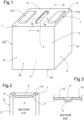
figure 1 is a schematic perspective view of a battery cell in one embodiment; -
figure 2 is a detail view of a section A-A offigure 1 ; -
figure 3 is a detail view of a section B-B offigure 1 ; -
figure 4 is a perspective view of a top cover of a battery cell according to an embodiment; -
figure 5 is a detail view of a section B-B ofFigure 4 ; -
figure 6 is an isometric perspective view of a battery module according to an embodiment. - Corresponding reference numerals refer to the same or corresponding parts in each of the figures.
- In the description and claims, for the sake of clarity, the terms longitudinal, transverse and vertical are adopted with reference to the X, Y, and Z trihedrons shown in the figures.
- With reference to
figure 1 , a body of a prismatic battery cell comprises a stack of electrodes (not illustrated), which is a repetitive arrangement of layers composed of a positive electrode, a separator, a negative electrode, and a separator. The positive electrodes connected to each other form apositive terminal 110, and the negative electrodes connected to each other form anegative terminal 110. - The
battery cell 100 comprises at least one stack of electrodes and two current collectors, one of the current collectors being connected to the cathodes of the stack of electrodes and the other current collector being connected to the anodes of the stack of electrodes, thebattery cell 100 having acasing 10 in which the stack of electrodes is housed. - The
casing 10 comprises acan 5 delimiting, at least in part, aninner space 2 of thecasing 10, saidcasing 10 having atop cover 6 to close theinner space 2 of thecasing 10 together with thecan 5. - The
can 5 thus has an opening '5' allowing access to theinner space 2 in order to be able to deposit elements inside thebattery cell 100, in particular the stack(s) of electrodes, the opening '5' then being closed by thetop cover 6. - The
can 5 has five sides, each side being formed of a generally rectangular plate made of sheet metal. Thetop cover 6 is also in the form of a generallyrectangular plate 1 made of sheet metal. The metal for the plates of the casing is for example aluminium, or more generally aluminium-based. - In this embodiment, the
can 5 of thecasing 10 comprises twoend plates 51 and twolateral plates 52 connecting theend plates 51 at both ends. Theend plates 51 and thelateral plates 52 are, for example, joined by welding. Thecan 5 of thecasing 10 typically has a rectangular box shape, delimiting a rectangular parallelepiped housing with a top opening '5', theend plates 51 being shorter in length than thelateral plates 52. In other words, the twoend plates 51 extend in vertical planes substantially parallel to each other (and parallel to the plane X-Z infigure 6 ), and the twolateral plates 52 extend in vertical planes substantially parallel to each other (and parallel to the plane Y-Z infigure 6 ) and perpendicular to the extension planes of theend plates 51. Theend plates 51 and thelateral plates 52 are connected with abottom plate 53 which closes a bottom opening, thebottom plate 53 extending in a horizontal plane substantially perpendicular to the planes of theend plates 51 and thelateral plates 52. - The
top cover 6 is also in the form of a plate which, in a closed position of thecasing 10 of thebattery cell 100, is positioned so that it extends in a horizontal plane substantially parallel to the plane of thebottom plate 53. - The assembly formed by the
can 5 and thetop cover 6 thus constitutes thecasing 10 closing theinner space 2 for housing a stack of electrodes, such acasing 10 having a generally prismatic shape for aprismatic battery cell 100. - According to the invention, at least one
plate 1 made of sheet metal has at least one stampedbead 3 protruding towards theinner space 2 of thecasing 10. - Such a
plate 1 consists of thetop cover 6, having (seefigures 4 and 5 ): - a length having a value L,
- a width having a value W; and
- a thickness having a value t;
- In this embodiment, one of the casing plates reinforced by a stamped bead comprises the
top cover 6. In a general way, this could be any plate of the exterior packaging part or component of thebattery cell 100. However, the most critical plate/face requiring said stamped bead(s) 3 is in practice thetop cover 6 and thebottom plate 53 of thebattery cells 100 assembled in amodule 101 and/or pack of a battery system for an electric vehicle. - The term "stamping", also known as "pressing", is the process of placing a flat sheet, preferably flat sheet metal, into a stamping press where a tool and die surface forms the metal into a net shape. Such a
bead 3 obtained by said stamping process, provides theplate 1, in this case thetop cover 6, with rigidity and resistance to bending without adding material. Moreover, such a process is particularly simple to implement and can be carried out in hidden time within the production line without needing to slow down the manufacturing process. - A
plate 1, such as thetop cover 6, having a slenderness ratio greater than 10 corresponds to aplate 1 whose thickness is relatively thin compared to its width. Such a characteristic induces a certain intrinsic flexibility of theplate 1. As the length L of theplate 1 is greater than its width W, if such a ratio based on the width W of theplate 1 is greater than a predetermined value, then so is a similar ratio based on the length L. If the plate is not rectangular, its width W corresponds to the minimum distance between two opposite points on itsperipheral edge 7. Preferably, and in other words, theplate 1 is delimited by aperipheral edge 7, the minimum distance between two points of thisperipheral edge 7 being greater than at least 10 times the value of an average thickness of the associatedplate 1. Such aplate 1, such as thetop cover 6, preferably each plate of thecasing 10, has an average thickness greater than or equal to 1 mm, still preferably greater than or equal to 2 mm and/or less than or equal to 5 mm, and still preferably less than or equal to 4 mm. - Both the stamped
bead 3 on thetop cover 6 and the associatedrecess 4 on the opposite face, facingouter space 2, extend rectilinearly. Furthermore, the stampedbead 3 on thetop cover 6 crosses a centerline C of the width W of theplate 1 and forms arecess 4 facing away from theinner space 2 of thecasing 100. - The associated
recess 4 has an average width value Q measured at the centerline C of the width W of thetop cover 6. Preferably, to ensure resilience, a satisfactory ratio between an average recess width and the average thickness of the plate is required, said average width value Q is greater than 0.3t and less than 3t. - In a general way, said average width value Q is greater than 0.3t, preferably greater than or equal to 0.5t, and less than 3t.
- The bending strength of the
plate 1, namely thetop cover 6, was found to be further enhanced with the stampedbead 3 having a height value P greater than 0.3t, and less than 3t. In a general way, said average width value P is greater than 0.3t, preferably greater than or equal to 0.5t and less than 3t, preferably less than or equal to 3t. - In this embodiment, the width W of the
recess 4, the height P of the stampedbead 3 and the depth of therecess 4, are each constant. Such a configuration provides a simple and easy to implement structure while guaranteeing improved resistance. - As can be seen in
Figure 1 , in particular, the stampedbead 3 and the associatedrecess 4 extend parallel to a width direction of theplate 1, i.e. transversely to theplate 1 formed by thetop cover 6. A straight or rectilinear shape parallel to a prismatic cell's width direction would be more effective, but it is not limited to being straight only; it could be curved or any shape. But, in general, in a preferred embodiment, the groove(s), formed by the stampedbead 3 and the associatedrecess 4, is arranged in a symmetric geometry to the centre lines of the length and/or, preferably and, of the width of abattery cell 100, considering thebattery cells 100 usually are in a symmetric shape to both centre lines of the length and width. - On the
plate 1, having at least one of said stampedbeads 3, here at least thetop cover 6, any part of the recess resides within a predetermined value from a centre-line of a length of theplate 1, said predetermined value being less than or equal to 30% of the value of the length L of theplate 1 along a length direction, in one direction or the other, still preferably less than or equal to 20%. - Similarly, any part of the
bead 3 and therecess 4 resides within a predetermined value from a centre-line of a width of theplate 1, said predetermined value being less than or equal to 30% of the value of the width W of theplate 1 along a width direction, in one direction or the other, still preferably less than or equal to 20%. - With reference to
figure 6 , abattery module 101 comprises acage 102 and abattery cell 100 array 100' held within saidcage 101. Thecage 101 comprises twoend plates 103 and twolateral plates 104 connecting theend plates 103 at both ends. Theend plates 103 and thelateral plates 104 are, for example, joined by welding. Thecage 101 typically has a rectangular box shape, delimiting a rectangular parallelepiped housing, theend plates 103 being shorter in length than thelateral plates 104. In other words, the twoend plates 103 extend in vertical planes substantially parallel to each other (and parallel to the plane X-Z infigure 6 ), and the twolateral plates 104 extend in vertical planes substantially parallel to each other (and parallel to the plane Y-Z infigure 6 ) and perpendicular to the extension planes of theend plates 104. - The battery cell array 100' is arranged within the housing of the
cage 101 and comprisesseveral battery cells 100 stacked along a longitudinal direction A, several thermal insulation pads, and several frames. Preferably, thebattery cells 100 array 100' further comprises two electrical insulation sheets (not illustrated). The longitudinal direction A extends along the axis Y infigure 6 . Thebattery cells 100 are typically (but not limited to) prismatic battery cells. Thebattery cells 100 form a stack ofbattery cells 100, each electrical insulation sheet 20 being arranged at a respective end of the stack ofbattery cells 100. The thermal insulation pads and the frames are inserted between thebattery cells 100 and separate thebattery cells 100 from each other in the longitudinal direction A. In other words, each set formed of a frame and a thermal insulation pad separates twobattery cells 100 from each other in the longitudinal direction A. The number of frames is, therefore, equal to the number of thermal insulation pads. - The two
end plates 103 of thecage 102 enclose thebattery cells 100 array in the longitudinal direction A (the twolateral plates 104 enclosing thebattery cells 100 array in the direction extending along the A axis infigure 6 ), eachend plate 103 covering a respective electrical insulation sheet. - Naturally, the present invention, as set forth, is given by way of example. It is understood that those skilled in the art may be able to carry out different variants of the invention without going beyond the scope of the invention.
- For example, the manufacture of the stamped
bead 3, dedicated solely to a reinforcing function, has been described here. It is understood that such a groove, formed by a stampedbead 3 and an associatedrecess 4 assembly, can be used to form an already existing element of theplate 1. In fact, and in general, it could be an additional groove or multiple grooves only to increase the flexural stiffness of the exterior packaging part/component of thebattery cell 100, i.e., thecasing 10. However, depending on the design, it may have some functional provisions within the groove, and it may become a combined groove with other functions, not only for stiffness enhancement. In an embodiment, the top cover has at least one break line of a gas venting area: said break line could be combined with the stampedbead 3 in principle, provided it works for both gas venting and enhancement of stiffness simultaneously. Said gas venting area can also be delimited by such a groove with a stampedbead 3. - It is emphasised that all the features, as apparent to a person skilled in the art from the present description, drawings and attached claims, even if said features have only been described in relation to certain other features, both individually and in any combination, may be combined with other features or groups of features disclosed herein, insofar as this has not been expressly ruled out or technical circumstances make such combinations impossible or meaningless.
Claims (17)
- A casing (10) for a battery cell (100) having at least one plate (1) made of sheet metal closing an inner space (2) of the casing (10) for housing a stack of electrodes, wherein the plate (1) has a length (L), a width having a value (W) and a thickness having a value (t) such that a slenderness ratio of the plate W/t is greater than 10, wherein the plate (1) has at least one stamped bead (3) protruding towards the inner space (2) of the casing (10), which crosses a centerline (C) of the width (W) of the plate (1) and forms a recess (4) facing away from the inner space (2) of the casing (100), the recess (4) having an average width value Q, measured at the centerline (C) of the width (W) of the plate (1), characterised in that the average width value Q is greater than 0.3t and less than 3t.
- The casing (10) according to claim 1, characterized in that the width (W) of the recess (4) is constant.
- The casing (10) according to claim 1 or 2, characterised in that the stamped bead (3) has a height value (P) greater than 0.3t, and less than 3t, the height (P) of the stamped bead (3) being preferably constant.
- The casing (10) according to any of the preceding claims, characterized in that the depth of the recess (4) is constant.
- The casing (10) according to any of the preceding claims, characterized in that said casing (10) has a symmetric shape to the centre line of the width (W).
- The casing (10) according to any one of the preceding claims, characterised in that the stamped bead (3) and the recess (4) extends rectilinearly.
- The casing (10) according to any one of the preceding claims, characterised in that the stamped bead (3) and the recess (4) extends parallel to a width direction of the plate (1).
- The casing (10) according to any of the preceding claims, characterised in that it has a prismatic shape for a prismatic battery cell (100).
- The casing (10) according to claim 8, characterized in that at least the plate (1) having the stamped bead (3), preferably each plate (1) of the casing (10), has a rectangular shape.
- The casing (10) according to any of the preceding claims, characterised in that it comprises a can (5) delimiting at least in part the inner space (2) of the casing (10), said casing (10) having a top cover (6) to close the inner space (2) of the casing (10) together with the can (5), at least one plate (1) having at least the stamped bead (3) being the top cover (6).
- The casing (10) according to any of the preceding claims, characterised in that at least the plate (1) having the stamped bead (3), preferably each plate of the casing (10), has an average thickness greater than or equal to 1 mm, still preferably greater than or equal to 2 mm and/or less than or equal to 5 mm, and still preferably less than or equal to 4 mm.
- The casing (10) according to any of the preceding claims, characterised in that at least the plate (1) having the stamped bead (3), preferably each plate of the casing (10), is delimited by a peripheral edge (7), the minimum distance between two points of this peripheral edge (7) being greater than or equal to at least 10 times the value of an average thickness of the associated plate (1).
- The casing (10) according to any of the preceding claims, characterised in that the stamped bead (3) is in a symmetric geometry to the centre lines of the length and/or, preferably and, of the width of the plate (1).
- The casing (10) according to any of the preceding claims, characterised in that, on the plate (1) having at least one of said stamped beads (3),- any part of the bead (3) and the recess (4) resides within a predetermined value from a centre-line of a length of the plate (1), said predetermined value being less than or equal to 30%, preferably less than or equal to 20%, of the value of the length (L) of the plate (1) along a length direction, and/or- any part of the bead (3) and the recess (4) resides within a predetermined value from a centre-line of a width of the plate (1), said predetermined value being less than or equal to 30%, preferably less than or equal to 20%, of the value of the width (W) of the plate (1) along a width direction,
- A battery cell (100) comprising at least one stack of electrodes and two current collectors, one of the current collectors being connected to the cathodes of the stack of electrodes and the other current collector being connected to the anodes of the stack of electrodes, the battery cell (100) having a casing (10) according to claims 1 to 14 in which the stack of electrodes is housed.
- A battery module (101) characterised in that it comprises a cage (102) and a battery cells (100) array held within said cage (101), the battery cells (100) array having at least one, preferably all, of the battery cells (100) according to claim 15.
- A battery pack characterised in that it comprises at least one battery module (101) according to claim 16.
Priority Applications (2)
| Application Number | Priority Date | Filing Date | Title |
|---|---|---|---|
| EP23305098.8A EP4407759A1 (en) | 2023-01-26 | 2023-01-26 | Casing of a battery cell |
| PCT/EP2024/051998 WO2024156909A1 (en) | 2023-01-26 | 2024-01-26 | Casing of a battery cell |
Applications Claiming Priority (1)
| Application Number | Priority Date | Filing Date | Title |
|---|---|---|---|
| EP23305098.8A EP4407759A1 (en) | 2023-01-26 | 2023-01-26 | Casing of a battery cell |
Publications (1)
| Publication Number | Publication Date |
|---|---|
| EP4407759A1 true EP4407759A1 (en) | 2024-07-31 |
Family
ID=85328565
Family Applications (1)
| Application Number | Title | Priority Date | Filing Date |
|---|---|---|---|
| EP23305098.8A Pending EP4407759A1 (en) | 2023-01-26 | 2023-01-26 | Casing of a battery cell |
Country Status (2)
| Country | Link |
|---|---|
| EP (1) | EP4407759A1 (en) |
| WO (1) | WO2024156909A1 (en) |
Citations (3)
| Publication number | Priority date | Publication date | Assignee | Title |
|---|---|---|---|---|
| KR20070088895A (en) * | 2006-02-27 | 2007-08-30 | 삼성에스디아이 주식회사 | Can for lithium secondary battery and lithium secondary battery using same |
| EP2482363A1 (en) * | 2011-01-31 | 2012-08-01 | SB LiMotive Co., Ltd. | Secondary battery |
| US9484561B2 (en) * | 2012-02-07 | 2016-11-01 | Lg Chem, Ltd. | Prismatic battery pack with novel structure |
-
2023
- 2023-01-26 EP EP23305098.8A patent/EP4407759A1/en active Pending
-
2024
- 2024-01-26 WO PCT/EP2024/051998 patent/WO2024156909A1/en not_active Ceased
Patent Citations (3)
| Publication number | Priority date | Publication date | Assignee | Title |
|---|---|---|---|---|
| KR20070088895A (en) * | 2006-02-27 | 2007-08-30 | 삼성에스디아이 주식회사 | Can for lithium secondary battery and lithium secondary battery using same |
| EP2482363A1 (en) * | 2011-01-31 | 2012-08-01 | SB LiMotive Co., Ltd. | Secondary battery |
| US9484561B2 (en) * | 2012-02-07 | 2016-11-01 | Lg Chem, Ltd. | Prismatic battery pack with novel structure |
Also Published As
| Publication number | Publication date |
|---|---|
| WO2024156909A1 (en) | 2024-08-02 |
Similar Documents
| Publication | Publication Date | Title |
|---|---|---|
| US11462790B2 (en) | Power supply device | |
| EP3848994A1 (en) | Battery pack including battery pack frame capable of preventing welding failure, and press jig for manufacturing same | |
| EP3800689B1 (en) | Secondary battery, battery module and electric vehicle | |
| EP2337106A2 (en) | Rechargeable battery | |
| CN110021725B (en) | Battery | |
| US20050221178A1 (en) | Electrode package and secondary battery using the same | |
| KR102760922B1 (en) | Batteries, electrical appliances and methods for manufacturing batteries | |
| KR101771088B1 (en) | Cap plate and secondary battery having the same | |
| JP2013055070A (en) | Battery pack | |
| CN111868958A (en) | Battery module and battery pack | |
| US10892453B2 (en) | Battery pack and method of manufacturing battery pack | |
| EP4407759A1 (en) | Casing of a battery cell | |
| KR20120096354A (en) | Rechargeable battery | |
| JP7705379B2 (en) | Battery Module | |
| EP4421967A1 (en) | Battery module comprising upper/lower-separable bus bar frame, and method for assembling same | |
| US20250174788A1 (en) | Battery module and battery module assembly method | |
| US20250174705A1 (en) | Battery pack | |
| EP4636913A1 (en) | Rechargeable battery | |
| JP7654638B2 (en) | Battery Module | |
| US20250385363A1 (en) | Battery module | |
| US20250300302A1 (en) | Electricity storage cell | |
| EP4726880A1 (en) | Battery module | |
| JP7630097B2 (en) | Energy Storage Module | |
| KR20250106814A (en) | Battery assembly and battery pack including the same | |
| WO2025078472A1 (en) | Battery cell with insulating element |
Legal Events
| Date | Code | Title | Description |
|---|---|---|---|
| PUAI | Public reference made under article 153(3) epc to a published international application that has entered the european phase |
Free format text: ORIGINAL CODE: 0009012 |
|
| STAA | Information on the status of an ep patent application or granted ep patent |
Free format text: STATUS: THE APPLICATION HAS BEEN PUBLISHED |
|
| AK | Designated contracting states |
Kind code of ref document: A1 Designated state(s): AL AT BE BG CH CY CZ DE DK EE ES FI FR GB GR HR HU IE IS IT LI LT LU LV MC ME MK MT NL NO PL PT RO RS SE SI SK SM TR |
|
| STAA | Information on the status of an ep patent application or granted ep patent |
Free format text: STATUS: REQUEST FOR EXAMINATION WAS MADE |
|
| 17P | Request for examination filed |
Effective date: 20241223 |