EP4407753A1 - Battery device - Google Patents
Battery device Download PDFInfo
- Publication number
- EP4407753A1 EP4407753A1 EP23861643.7A EP23861643A EP4407753A1 EP 4407753 A1 EP4407753 A1 EP 4407753A1 EP 23861643 A EP23861643 A EP 23861643A EP 4407753 A1 EP4407753 A1 EP 4407753A1
- Authority
- EP
- European Patent Office
- Prior art keywords
- battery
- frame
- heat dissipation
- battery cell
- battery device
- Prior art date
- Legal status (The legal status is an assumption and is not a legal conclusion. Google has not performed a legal analysis and makes no representation as to the accuracy of the status listed.)
- Pending
Links
Images



Classifications
-
- H—ELECTRICITY
- H01—ELECTRIC ELEMENTS
- H01M—PROCESSES OR MEANS, e.g. BATTERIES, FOR THE DIRECT CONVERSION OF CHEMICAL ENERGY INTO ELECTRICAL ENERGY
- H01M10/00—Secondary cells; Manufacture thereof
- H01M10/60—Heating or cooling; Temperature control
- H01M10/61—Types of temperature control
- H01M10/617—Types of temperature control for achieving uniformity or desired distribution of temperature
-
- H—ELECTRICITY
- H01—ELECTRIC ELEMENTS
- H01M—PROCESSES OR MEANS, e.g. BATTERIES, FOR THE DIRECT CONVERSION OF CHEMICAL ENERGY INTO ELECTRICAL ENERGY
- H01M10/00—Secondary cells; Manufacture thereof
- H01M10/60—Heating or cooling; Temperature control
- H01M10/61—Types of temperature control
- H01M10/613—Cooling or keeping cold
-
- H—ELECTRICITY
- H01—ELECTRIC ELEMENTS
- H01M—PROCESSES OR MEANS, e.g. BATTERIES, FOR THE DIRECT CONVERSION OF CHEMICAL ENERGY INTO ELECTRICAL ENERGY
- H01M10/00—Secondary cells; Manufacture thereof
- H01M10/60—Heating or cooling; Temperature control
- H01M10/64—Heating or cooling; Temperature control characterised by the shape of the cells
- H01M10/647—Prismatic or flat cells, e.g. pouch cells
-
- H—ELECTRICITY
- H01—ELECTRIC ELEMENTS
- H01M—PROCESSES OR MEANS, e.g. BATTERIES, FOR THE DIRECT CONVERSION OF CHEMICAL ENERGY INTO ELECTRICAL ENERGY
- H01M10/00—Secondary cells; Manufacture thereof
- H01M10/60—Heating or cooling; Temperature control
- H01M10/65—Means for temperature control structurally associated with the cells
- H01M10/653—Means for temperature control structurally associated with the cells characterised by electrically insulating or thermally conductive materials
-
- H—ELECTRICITY
- H01—ELECTRIC ELEMENTS
- H01M—PROCESSES OR MEANS, e.g. BATTERIES, FOR THE DIRECT CONVERSION OF CHEMICAL ENERGY INTO ELECTRICAL ENERGY
- H01M10/00—Secondary cells; Manufacture thereof
- H01M10/60—Heating or cooling; Temperature control
- H01M10/65—Means for temperature control structurally associated with the cells
- H01M10/655—Solid structures for heat exchange or heat conduction
- H01M10/6551—Surfaces specially adapted for heat dissipation or radiation, e.g. fins or coatings
-
- H—ELECTRICITY
- H01—ELECTRIC ELEMENTS
- H01M—PROCESSES OR MEANS, e.g. BATTERIES, FOR THE DIRECT CONVERSION OF CHEMICAL ENERGY INTO ELECTRICAL ENERGY
- H01M10/00—Secondary cells; Manufacture thereof
- H01M10/60—Heating or cooling; Temperature control
- H01M10/65—Means for temperature control structurally associated with the cells
- H01M10/655—Solid structures for heat exchange or heat conduction
- H01M10/6554—Rods or plates
-
- H—ELECTRICITY
- H01—ELECTRIC ELEMENTS
- H01M—PROCESSES OR MEANS, e.g. BATTERIES, FOR THE DIRECT CONVERSION OF CHEMICAL ENERGY INTO ELECTRICAL ENERGY
- H01M50/00—Constructional details or processes of manufacture of the non-active parts of electrochemical cells other than fuel cells, e.g. hybrid cells
- H01M50/20—Mountings; Secondary casings or frames; Racks, modules or packs; Suspension devices; Shock absorbers; Transport or carrying devices; Holders
- H01M50/204—Racks, modules or packs for multiple batteries or multiple cells
- H01M50/207—Racks, modules or packs for multiple batteries or multiple cells characterised by their shape
- H01M50/211—Racks, modules or packs for multiple batteries or multiple cells characterised by their shape adapted for pouch cells
-
- H—ELECTRICITY
- H01—ELECTRIC ELEMENTS
- H01M—PROCESSES OR MEANS, e.g. BATTERIES, FOR THE DIRECT CONVERSION OF CHEMICAL ENERGY INTO ELECTRICAL ENERGY
- H01M50/00—Constructional details or processes of manufacture of the non-active parts of electrochemical cells other than fuel cells, e.g. hybrid cells
- H01M50/20—Mountings; Secondary casings or frames; Racks, modules or packs; Suspension devices; Shock absorbers; Transport or carrying devices; Holders
- H01M50/284—Mountings; Secondary casings or frames; Racks, modules or packs; Suspension devices; Shock absorbers; Transport or carrying devices; Holders with incorporated circuit boards, e.g. printed circuit boards [PCB]
-
- H—ELECTRICITY
- H01—ELECTRIC ELEMENTS
- H01M—PROCESSES OR MEANS, e.g. BATTERIES, FOR THE DIRECT CONVERSION OF CHEMICAL ENERGY INTO ELECTRICAL ENERGY
- H01M50/00—Constructional details or processes of manufacture of the non-active parts of electrochemical cells other than fuel cells, e.g. hybrid cells
- H01M50/20—Mountings; Secondary casings or frames; Racks, modules or packs; Suspension devices; Shock absorbers; Transport or carrying devices; Holders
- H01M50/289—Mountings; Secondary casings or frames; Racks, modules or packs; Suspension devices; Shock absorbers; Transport or carrying devices; Holders characterised by spacing elements or positioning means within frames, racks or packs
-
- Y—GENERAL TAGGING OF NEW TECHNOLOGICAL DEVELOPMENTS; GENERAL TAGGING OF CROSS-SECTIONAL TECHNOLOGIES SPANNING OVER SEVERAL SECTIONS OF THE IPC; TECHNICAL SUBJECTS COVERED BY FORMER USPC CROSS-REFERENCE ART COLLECTIONS [XRACs] AND DIGESTS
- Y02—TECHNOLOGIES OR APPLICATIONS FOR MITIGATION OR ADAPTATION AGAINST CLIMATE CHANGE
- Y02E—REDUCTION OF GREENHOUSE GAS [GHG] EMISSIONS, RELATED TO ENERGY GENERATION, TRANSMISSION OR DISTRIBUTION
- Y02E60/00—Enabling technologies; Technologies with a potential or indirect contribution to GHG emissions mitigation
- Y02E60/10—Energy storage using batteries
Definitions
- the present disclosure relates to an electronic device, more particularly, to a battery device.
- the present application claims priority to Korean Patent Application No. 10-2022-0175068 filed on December 14, 2022 in the Republic of Korea, the disclosures of which are incorporated herein by reference.
- Portable electronic products include a battery device to provide necessary power.
- the battery device includes a plurality of battery cells, and each battery cell generates heat during charging and discharging, so that the temperature rises.
- battery cells in an overheated state are easily consumed or have a potential risk of explosion, which affects the life span of the battery cell.
- the present disclosure is directed to providing a battery device capable of effectively extending the cycle life of battery cells by forming thermal balance between the battery cells.
- a battery device which includes a battery module and a printing layer.
- the battery module includes a frame and a plurality of battery cells disposed within the frame.
- the frame has a plurality of heat dissipation slots spaced apart from each other to transfer heat generated in at least one of the battery cells to the outside of the frame so that the battery cells reach thermal balance.
- the printing layer covers the frame of the battery module and directly contacts the heat dissipation slots.
- the battery cells may include at least one first battery cell and at least one second battery cell, and the temperature generated in the at least one first battery cell may be higher than the temperature generated in at least one second battery cell.
- the heat dissipation slots may be installed to correspond to the position of the at least one first battery cell.
- each of the heat dissipation slots may extend from a side of the frame toward a bottom surface to form an L shape.
- the frame may have a thickness of 0.7 mm.
- each heat dissipation slot may have an aspect ratio greater than 1 and equal to or less than 2.5.
- the battery module may further include a plurality of separation plates located within the frame to divide the frame into a plurality of accommodation areas, and the battery cells may be located within the accommodation areas, respectively.
- the battery device may further comprise a printed board disposed on the frame of the battery module and electrically connected to the battery cell, and a protection plate disposed on the frame to cover the printed board.
- the battery device may further comprise a protection layer, and the battery module may be located between the printing layer and the protection layer.
- each battery cell may include a soft pack battery cell.
- the frame has a heat dissipation slot to transmit heat generated in at least one battery cell to the outside of the frame, thereby lowering the temperature of the battery cell to reach thermal balance between the battery cells.
- the heat dissipation slot by installing the heat dissipation slot, heat dissipation is performed in a heat convection method and the heat dissipation area is increased, so that the battery cells reach the same or similar temperatures to effectively extend the cycle life of the battery cells.
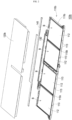
- FIG. 1a is a three-dimensional exploded perspective view showing a battery device according to an embodiment of the present disclosure.
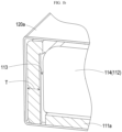
- FIG. 1b is a local three-dimensional cross-sectional perspective view showing the battery device in FIG. 1a .
- FIG. 1c is a local three-dimensional cross-sectional perspective view, observed in a direction different from of FIG. 1b .
- FIG. 1d is a local three-dimensional cross-sectional perspective view showing a frame in FIG. 1a .
- the printing layer of FIG. 1b is not depicted in FIG. 1c .
- a battery device 100a is a battery device used in, for example, a notebook computer or other types of electronic products, and includes a battery module 110a and a printing layer 120a.
- the battery module 110a includes a frame 111a and a plurality of battery cells (three battery cells 112 are shown as an example) disposed within the frame 111a.
- the frame 111a includes a plurality of heat dissipation slots 113 spaced apart from each other to transfer heat generated in at least one battery cell 112 to the outside of the frame 111a so that the battery cell 112 reaches thermal balance.
- the printing layer 120a covers the frame 111a of the battery module 110a and directly contacts the heat dissipation slot 113.
- the battery module 110a also includes a plurality of separation plates 115a, and the separation plates 115a are located within the frame 111a to divide the frame 111a into a plurality of accommodation areas (e.g., three accommodation areas A), and each battery cell 112 is located within the accommodation area A.
- the battery cell 112 may be a soft pack battery cell, but is not limited thereto.
- the battery cell 112 according to this embodiment includes at least one first battery cell (two first battery cells 114 are shown as an example) and at least one second battery cell (one second battery cell 116 are shown as an example), and the temperature generated when the first battery cell 114 is charged and discharged is higher than the temperature generated when the second battery cell 116 is charged and discharged.
- the heat dissipation slot 113 is a slot hole passing through the frame 111a, and the heat dissipation slot 113 extends from the side S of the frame 111a to the bottom surface U to form a L shape. That is, the airflow within the frame 111a is transferred to the outside of the frame 111a through the heat dissipation slot 113.
- the heat dissipation slot 113 according to this embodiment is installed to correspond to the position of the first battery cell 114 and is installed in the side S of the frame 111a.
- the first battery cell 114 located within the frame 111a directly contacts the heat dissipation slot 113. Since the heat dissipation slot 113 communicates the printing layer 120 and the inside of the frame 111a, the heat of the first battery cell 114 is transferred to the printing layer 120 in a heat convection method.
- the heat dissipation slot 113 is installed to correspond to the first battery cell 114 having a high temperature, and the heat dissipation slot 113 is not installed around the second battery cell 116 having a low temperature. Therefore, the heat dissipation slot 113 transfers the heat generated in the first battery cell 114 to the outside of the frame 111a in a thermal convection method, thereby lowering the temperature of the first battery cell 114 (e.g., by 2.35°C), so that the temperature of the first battery cell 114 reaches thermal balance with the temperature of the second the battery cell 116.
- the thickness T of the frame 111a is, for example, 0.7 mm, and the ratio of width and depth (aspect ratio) of each heat dissipation slot 113 is greater than 1 and equal to or less than 2.5.
- the depth D of each heat dissipation slot 113 is, for example, 0.2 mm, and the width W of each heat dissipation slot 113 is, for example, 0.5 mm.
- the heat dissipation slot 113 is installed only in the side S of the frame 111a, but in other embodiments, the heat dissipation slot 113 may be installed in two or three sides of the battery cell 112 corresponding to the heat dissipation demand, which also falls within the scope of protection of the present disclosure.
- the battery device 100a includes a printed board 130 and a protection plate 140.
- the printed board 130 is disposed on the frame 111a of the battery module 110a and electrically connected to the battery cell 112.
- the protection plate 140 is disposed on the frame 111a to cover the printed board 130 to protect the printed board 130.
- the material of the frame 111a and the material of the protection plate 140 may be plastic.
- the battery device 100a includes a protection layer 150, and the battery module 110a is located between the printing layer 120a and the protection layer 150.
- the protection layer 150 may be a sheet material of a single color, and is disposed on the bottom surface U of the frame 111a to cover the battery module 110a together with the printing layer 120a.
- the printing layer 120a may include text or images to display information such as a model name of the battery device 100a, and thus the printing layer 120a may be regarded as a label layer.
- the frame 111a according to this embodiment has a heat dissipation slot 113, and by installing the heat dissipation slot 113, cooling conditions may be improved and the heat dissipation area of the battery cell 112 may be increased. Also, since the heat generated in the battery cell 112 with a high temperature is transferred to the outside of the frame 111a in a heat convection method, the temperature of the corresponding battery cell 112 is lowered so that the battery cells 112 reach thermal balance. Therefore, the temperatures of the battery cells 112 of the battery device 100a according to this embodiment becomes the same or similar, so that the cycle life of the battery cell 112 may be effectively extended. In addition, by installing the heat dissipation slot 113 on the frame 111a, the heat dissipation control system of the battery device 100a may be simplified and the use of insulation materials may be reduced.
- FIG. 2 is a three-dimensional exploded perspective view showing a battery device according to another embodiment of the present disclosure.
- the battery device 100b according to this embodiment is similar to the battery device 100a in FIG. 1a , except that, in this embodiment, the frame 11 1b of the battery module 110b is divided into four accommodation spaces B by a separation plate 115b, and four battery cells 112 are located in the accommodation spaces B, respectively.
- the heat dissipation slot 113 is installed to correspond to each battery cell 112. Also, since the battery cell 112 having a high temperature corresponds to the plurality of heat dissipation slots 113, the battery cells 112 reach thermal balance, and the cycle life of the battery cells 112 may be effectively extended.
- the number of installed heat dissipation slots 113 may be determined according to the heat dissipation demand of the battery cells 112 and the length of the frame 111b.
- the battery cell 112 having a high temperature may have heat dissipation slots 113 installed with a large number and high density.
- the frame has a heat dissipation slot to transfer heat generated in at least one battery cell to the outside of the frame, thereby lowering the temperature of the battery cell so that the battery cells reach thermal balance.
- a heat dissipation slot by installing a heat dissipation slot, heat dissipation is performed in a heat convection method and the heat dissipation area is increased, so that the battery cells reaches the same or similar temperatures, thereby effectively extending the cycle life of the battery cells.
Landscapes
- Chemical & Material Sciences (AREA)
- Chemical Kinetics & Catalysis (AREA)
- Electrochemistry (AREA)
- General Chemical & Material Sciences (AREA)
- Engineering & Computer Science (AREA)
- Manufacturing & Machinery (AREA)
- Secondary Cells (AREA)
- Battery Mounting, Suspending (AREA)
Abstract
Description
- The present disclosure relates to an electronic device, more particularly, to a battery device. The present application claims priority to
Korean Patent Application No. 10-2022-0175068 filed on December 14, 2022 - Portable electronic products (e.g., notebooks) include a battery device to provide necessary power. The battery device includes a plurality of battery cells, and each battery cell generates heat during charging and discharging, so that the temperature rises. However, battery cells in an overheated state are easily consumed or have a potential risk of explosion, which affects the life span of the battery cell.
- The present disclosure is directed to providing a battery device capable of effectively extending the cycle life of battery cells by forming thermal balance between the battery cells.
- In one aspect of the present disclosure, there is provided a battery device, which includes a battery module and a printing layer. The battery module includes a frame and a plurality of battery cells disposed within the frame. The frame has a plurality of heat dissipation slots spaced apart from each other to transfer heat generated in at least one of the battery cells to the outside of the frame so that the battery cells reach thermal balance. The printing layer covers the frame of the battery module and directly contacts the heat dissipation slots.
- In an embodiment of the present disclosure, the battery cells may include at least one first battery cell and at least one second battery cell, and the temperature generated in the at least one first battery cell may be higher than the temperature generated in at least one second battery cell.
- In an embodiment of the present disclosure, the heat dissipation slots may be installed to correspond to the position of the at least one first battery cell.
- In an embodiment of the present disclosure, each of the heat dissipation slots may extend from a side of the frame toward a bottom surface to form an L shape.
- In an embodiment of the present disclosure, the frame may have a thickness of 0.7 mm.
- In an embodiment of the present disclosure, each heat dissipation slot may have an aspect ratio greater than 1 and equal to or less than 2.5.
- In an embodiment of the present disclosure, the battery module may further include a plurality of separation plates located within the frame to divide the frame into a plurality of accommodation areas, and the battery cells may be located within the accommodation areas, respectively.
- In an embodiment of the present disclosure, the battery device may further comprise a printed board disposed on the frame of the battery module and electrically connected to the battery cell, and a protection plate disposed on the frame to cover the printed board.
- In an embodiment of the present disclosure, the battery device may further comprise a protection layer, and the battery module may be located between the printing layer and the protection layer.
- In an embodiment of the present disclosure, each battery cell may include a soft pack battery cell.
- According to the above, in the design of the battery device according to the present disclosure, the frame has a heat dissipation slot to transmit heat generated in at least one battery cell to the outside of the frame, thereby lowering the temperature of the battery cell to reach thermal balance between the battery cells. In other words, by installing the heat dissipation slot, heat dissipation is performed in a heat convection method and the heat dissipation area is increased, so that the battery cells reach the same or similar temperatures to effectively extend the cycle life of the battery cells.
-
-
FIG. 1a is a three-dimensional exploded perspective view showing a battery device according to an embodiment of the present disclosure. -
FIG. 1b is a local three-dimensional cross-sectional perspective view showing the battery device inFIG. 1a . -
FIG. 1c is a local three-dimensional cross-sectional perspective view, observed in a direction different from ofFIG. 1b . -
FIG. 1d is a local three-dimensional cross-sectional perspective view showing a frame inFIG. 1a . -
FIG. 2 is a three-dimensional exploded perspective view showing a battery device according to another embodiment of the present disclosure. - In order to understand the features and advantages of the present disclosure more clearly and easily, a detailed description is provided in conjunction with the drawings through the following embodiment.
- The present disclosure can be understood by referring to the following detailed description and the accompanying drawings, and it should be noted that for easy understanding of the present disclosure and conciseness of the drawings, the structures in the drawings are not drawn to scale. In addition, the quantity and size of each component in the drawing is only an example and does not limit the present disclosure.
-
FIG. 1a is a three-dimensional exploded perspective view showing a battery device according to an embodiment of the present disclosure.FIG. 1b is a local three-dimensional cross-sectional perspective view showing the battery device inFIG. 1a .FIG. 1c is a local three-dimensional cross-sectional perspective view, observed in a direction different from ofFIG. 1b .FIG. 1d is a local three-dimensional cross-sectional perspective view showing a frame inFIG. 1a . For convenience of description, the printing layer ofFIG. 1b is not depicted inFIG. 1c . - Referring to
FIG. 1a , in this embodiment, abattery device 100a is a battery device used in, for example, a notebook computer or other types of electronic products, and includes abattery module 110a and aprinting layer 120a. Thebattery module 110a includes aframe 111a and a plurality of battery cells (threebattery cells 112 are shown as an example) disposed within theframe 111a. Theframe 111a includes a plurality ofheat dissipation slots 113 spaced apart from each other to transfer heat generated in at least onebattery cell 112 to the outside of theframe 111a so that thebattery cell 112 reaches thermal balance. Theprinting layer 120a covers theframe 111a of thebattery module 110a and directly contacts theheat dissipation slot 113. - In detail, in this embodiment, the
battery module 110a also includes a plurality ofseparation plates 115a, and theseparation plates 115a are located within theframe 111a to divide theframe 111a into a plurality of accommodation areas (e.g., three accommodation areas A), and eachbattery cell 112 is located within the accommodation area A. In one embodiment, thebattery cell 112 may be a soft pack battery cell, but is not limited thereto. In addition, thebattery cell 112 according to this embodiment includes at least one first battery cell (twofirst battery cells 114 are shown as an example) and at least one second battery cell (onesecond battery cell 116 are shown as an example), and the temperature generated when thefirst battery cell 114 is charged and discharged is higher than the temperature generated when thesecond battery cell 116 is charged and discharged. - Referring to
FIGS. 1b ,1c , and1d together, in this embodiment, theheat dissipation slot 113 is a slot hole passing through theframe 111a, and theheat dissipation slot 113 extends from the side S of theframe 111a to the bottom surface U to form a L shape. That is, the airflow within theframe 111a is transferred to the outside of theframe 111a through theheat dissipation slot 113. As shown inFIGS. 1a and1b , theheat dissipation slot 113 according to this embodiment is installed to correspond to the position of thefirst battery cell 114 and is installed in the side S of theframe 111a. Here, thefirst battery cell 114 located within theframe 111a directly contacts theheat dissipation slot 113. Since theheat dissipation slot 113 communicates the printing layer 120 and the inside of theframe 111a, the heat of thefirst battery cell 114 is transferred to the printing layer 120 in a heat convection method. - In short, the
heat dissipation slot 113 according to this embodiment is installed to correspond to thefirst battery cell 114 having a high temperature, and theheat dissipation slot 113 is not installed around thesecond battery cell 116 having a low temperature. Therefore, theheat dissipation slot 113 transfers the heat generated in thefirst battery cell 114 to the outside of theframe 111a in a thermal convection method, thereby lowering the temperature of the first battery cell 114 (e.g., by 2.35°C), so that the temperature of thefirst battery cell 114 reaches thermal balance with the temperature of the second thebattery cell 116. - Referring to
FIGS. 1b to 1d again, in one embodiment, the thickness T of theframe 111a is, for example, 0.7 mm, and the ratio of width and depth (aspect ratio) of eachheat dissipation slot 113 is greater than 1 and equal to or less than 2.5. In one embodiment, the depth D of eachheat dissipation slot 113 is, for example, 0.2 mm, and the width W of eachheat dissipation slot 113 is, for example, 0.5 mm. In this embodiment, theheat dissipation slot 113 is installed only in the side S of theframe 111a, but in other embodiments, theheat dissipation slot 113 may be installed in two or three sides of thebattery cell 112 corresponding to the heat dissipation demand, which also falls within the scope of protection of the present disclosure. - Also, referring to
FIG. 1a again, thebattery device 100a according to this embodiment includes a printedboard 130 and aprotection plate 140. The printedboard 130 is disposed on theframe 111a of thebattery module 110a and electrically connected to thebattery cell 112. Theprotection plate 140 is disposed on theframe 111a to cover the printedboard 130 to protect the printedboard 130. In one embodiment, the material of theframe 111a and the material of theprotection plate 140 may be plastic. In addition, thebattery device 100a includes aprotection layer 150, and thebattery module 110a is located between theprinting layer 120a and theprotection layer 150. Here, theprotection layer 150 may be a sheet material of a single color, and is disposed on the bottom surface U of theframe 111a to cover thebattery module 110a together with theprinting layer 120a. Theprinting layer 120a may include text or images to display information such as a model name of thebattery device 100a, and thus theprinting layer 120a may be regarded as a label layer. - In short, the
frame 111a according to this embodiment has aheat dissipation slot 113, and by installing theheat dissipation slot 113, cooling conditions may be improved and the heat dissipation area of thebattery cell 112 may be increased. Also, since the heat generated in thebattery cell 112 with a high temperature is transferred to the outside of theframe 111a in a heat convection method, the temperature of thecorresponding battery cell 112 is lowered so that thebattery cells 112 reach thermal balance. Therefore, the temperatures of thebattery cells 112 of thebattery device 100a according to this embodiment becomes the same or similar, so that the cycle life of thebattery cell 112 may be effectively extended. In addition, by installing theheat dissipation slot 113 on theframe 111a, the heat dissipation control system of thebattery device 100a may be simplified and the use of insulation materials may be reduced. - Here, it should be noted that the following embodiment follows the reference signs and some contents of the former embodiment, and it should be noted that the same reference signs denote the same or similar components and the same technical features will not be described again. For the features not described below, reference may be made to the former embodiment, and the corresponding features will not be described again in the following embodiment.
-
FIG. 2 is a three-dimensional exploded perspective view showing a battery device according to another embodiment of the present disclosure. Referring toFIGS. 1a and2 together, thebattery device 100b according to this embodiment is similar to thebattery device 100a inFIG. 1a , except that, in this embodiment, the frame 11 1b of thebattery module 110b is divided into four accommodation spaces B by aseparation plate 115b, and fourbattery cells 112 are located in the accommodation spaces B, respectively. Here, theheat dissipation slot 113 is installed to correspond to eachbattery cell 112. Also, since thebattery cell 112 having a high temperature corresponds to the plurality ofheat dissipation slots 113, thebattery cells 112 reach thermal balance, and the cycle life of thebattery cells 112 may be effectively extended. The number of installedheat dissipation slots 113 may be determined according to the heat dissipation demand of thebattery cells 112 and the length of theframe 111b. Here, thebattery cell 112 having a high temperature may haveheat dissipation slots 113 installed with a large number and high density. - As described above, in the design of the battery device according to the present disclosure, the frame has a heat dissipation slot to transfer heat generated in at least one battery cell to the outside of the frame, thereby lowering the temperature of the battery cell so that the battery cells reach thermal balance. In other words, by installing a heat dissipation slot, heat dissipation is performed in a heat convection method and the heat dissipation area is increased, so that the battery cells reaches the same or similar temperatures, thereby effectively extending the cycle life of the battery cells.
- The present disclosure has been described through the embodiment as described above, but is not limited thereto, and appropriate changes and modifications can be made by those skilled in the art within the range that does not deviate from the purpose of the present disclosure, and the scope of protection of the present disclosure shall be based on the appended claims.
-
- 100a, 100b: battery device
- 110a, 110b: battery module
- 111a, 111b: frame
- 112: battery cell
- 113: heat dissipation slot
- 114: first battery cell
- 115a, 115b: separation plate
- 116: second battery cell
- 120a, 120b: printing layer
- 130: printed board
- 140: protection plate
- 150: protection layer
- A: accommodation area
- D: depth
- L: width
- S: side
- T: thickness
- U: bottom surface
- W: slot width
Claims (10)
- A battery device, comprising:a battery module including a frame and a plurality of battery cells disposed within the frame, the frame having a plurality of heat dissipation slots spaced apart from each other to transfer heat generated in at least one of the battery cells to the outside of the frame so that the battery cells reach thermal balance, anda printing layer configured to cover the frame of the battery module and directly connected to the heat dissipation slots.
- The battery device according to claim 1,
wherein the battery cells include at least one first battery cell and at least one second battery cell, and the temperature generated in the at least one first battery cell is higher than the temperature generated in at least one second battery cell. - The battery device according to claim 2,
wherein the heat dissipation slots are installed to correspond to the position of the at least one first battery cell. - The battery device according to claim 1,
wherein each of the heat dissipation slots extends from a side of the frame toward a bottom surface to form an L shape. - The battery device according to claim 1,
wherein the frame has a thickness of 0.7 mm. - The battery device according to claim 5,
wherein each heat dissipation slot has an aspect ratio greater than 1 and equal to or less than 2.5. - The battery device according to claim 1,
wherein the battery module further includes a plurality of separation plates located within the frame to divide the frame into a plurality of accommodation areas, and the battery cells are located within the accommodation areas, respectively. - The battery device according to claim 1, further comprising:a printed board disposed on the frame of the battery module and electrically connected to the battery cell, anda protection plate disposed on the frame to cover the printed board.
- The battery device according to claim 1, further comprising a protection layer,
wherein the battery module is located between the printing layer and the protection layer. - The battery device according to claim 1,
wherein each battery cell includes a soft pack battery cell.
Applications Claiming Priority (2)
| Application Number | Priority Date | Filing Date | Title |
|---|---|---|---|
| KR1020220175068A KR20240092366A (en) | 2022-12-14 | 2022-12-14 | Battery device |
| PCT/KR2023/005689 WO2024128431A1 (en) | 2022-12-14 | 2023-04-26 | Battery device |
Publications (2)
| Publication Number | Publication Date |
|---|---|
| EP4407753A1 true EP4407753A1 (en) | 2024-07-31 |
| EP4407753A4 EP4407753A4 (en) | 2025-04-23 |
Family
ID=90366801
Family Applications (1)
| Application Number | Title | Priority Date | Filing Date |
|---|---|---|---|
| EP23861643.7A Pending EP4407753A4 (en) | 2022-12-14 | 2023-04-26 | Battery device |
Country Status (5)
| Country | Link |
|---|---|
| EP (1) | EP4407753A4 (en) |
| JP (1) | JP7721801B2 (en) |
| KR (1) | KR20240092366A (en) |
| CN (1) | CN118613945A (en) |
| WO (1) | WO2024128431A1 (en) |
Family Cites Families (13)
| Publication number | Priority date | Publication date | Assignee | Title |
|---|---|---|---|---|
| JP2002141114A (en) | 2000-10-31 | 2002-05-17 | Sanyo Electric Co Ltd | Battery pack |
| TW200843158A (en) * | 2007-04-20 | 2008-11-01 | Ama Precision Inc | Thermally enhanced battery module |
| KR101030856B1 (en) * | 2008-12-16 | 2011-04-22 | 삼성에스디아이 주식회사 | Battery pack |
| JP2011049012A (en) * | 2009-08-26 | 2011-03-10 | Sanyo Electric Co Ltd | Battery pack |
| JP2011154986A (en) * | 2010-01-28 | 2011-08-11 | Sanyo Electric Co Ltd | Battery pack |
| KR101543071B1 (en) * | 2013-07-02 | 2015-08-07 | 현대자동차주식회사 | Method for battery temperature control |
| KR102161628B1 (en) * | 2014-03-14 | 2020-10-05 | 삼성에스디아이 주식회사 | Protection circuit module for battery and battery pack comprising the same |
| KR102214949B1 (en) * | 2016-05-24 | 2021-02-10 | 삼성에스디아이 주식회사 | Battery pack |
| CN107785511B (en) * | 2016-08-30 | 2019-11-22 | 比亚迪股份有限公司 | Battery modules, power battery packs and automobiles |
| KR102656440B1 (en) * | 2019-02-01 | 2024-04-09 | 주식회사 엘지에너지솔루션 | Battery module |
| KR102381762B1 (en) | 2019-02-21 | 2022-03-31 | 주식회사 엘지에너지솔루션 | Battery module including protection cover covering flexible printed circuit board |
| CN210136909U (en) * | 2019-06-18 | 2020-03-10 | 宁德时代新能源科技股份有限公司 | Temperature control assembly and battery pack |
| CN210744060U (en) * | 2019-11-19 | 2020-06-12 | 宁德时代新能源科技股份有限公司 | Soft-pack battery modules, battery packs, and devices using soft-pack battery modules as power sources |
-
2022
- 2022-12-14 KR KR1020220175068A patent/KR20240092366A/en active Pending
-
2023
- 2023-04-26 WO PCT/KR2023/005689 patent/WO2024128431A1/en not_active Ceased
- 2023-04-26 JP JP2024518221A patent/JP7721801B2/en active Active
- 2023-04-26 EP EP23861643.7A patent/EP4407753A4/en active Pending
- 2023-04-26 CN CN202380018024.7A patent/CN118613945A/en active Pending
Also Published As
| Publication number | Publication date |
|---|---|
| JP2025501841A (en) | 2025-01-24 |
| JP7721801B2 (en) | 2025-08-12 |
| KR20240092366A (en) | 2024-06-24 |
| WO2024128431A1 (en) | 2024-06-20 |
| EP4407753A4 (en) | 2025-04-23 |
| CN118613945A (en) | 2024-09-06 |
Similar Documents
| Publication | Publication Date | Title |
|---|---|---|
| EP3660974B1 (en) | Battery module having heat dissipation plate | |
| EP3657595B1 (en) | Battery module and battery pack comprising same | |
| JP6600701B2 (en) | Battery module having improved fastening structure | |
| KR102389469B1 (en) | Battery pack | |
| CN108886183B (en) | Battery module with heat-dissipating packaging material and method therefor | |
| WO2016204489A1 (en) | Cell cover for secondary battery, and battery module comprising same | |
| CN110574220A (en) | battery module | |
| CN114128020B (en) | Battery module and battery pack including the battery module | |
| KR102514497B1 (en) | Battery module and battery packr including the same | |
| CN111033879A (en) | Battery pack with bidirectional cooling structure | |
| KR20200019504A (en) | Battery Pack Having Battery Frame | |
| CN116114116A (en) | Battery module and battery pack including the battery module | |
| EP4407753A1 (en) | Battery device | |
| CN112366413B (en) | battery unit | |
| EP4425683A1 (en) | Fixing support for flexible circuit board, bus component, battery, and electric device | |
| EP4068463B1 (en) | Battery charging/discharging system including cooling unit enabling uniform flow rate distribution | |
| EP4099489B1 (en) | Battery pack comprising heat dissipation structure of protective circuit module using heat dissipation tape | |
| TW202424690A (en) | Battery device | |
| TW201044669A (en) | Rechargeable battery | |
| US20190393575A1 (en) | Battery cooling and heating device and battery incorporating such a device | |
| EP4415141A1 (en) | Battery pack | |
| US20260106202A1 (en) | Heating structure, heating bank, and battery production device | |
| CN219979637U (en) | Battery module and electric equipment | |
| EP4668439A1 (en) | Battery assembly and battery pack including same | |
| CN221928240U (en) | A kind of battery core heat dissipation structure |
Legal Events
| Date | Code | Title | Description |
|---|---|---|---|
| STAA | Information on the status of an ep patent application or granted ep patent |
Free format text: STATUS: UNKNOWN |
|
| STAA | Information on the status of an ep patent application or granted ep patent |
Free format text: STATUS: THE INTERNATIONAL PUBLICATION HAS BEEN MADE |
|
| PUAI | Public reference made under article 153(3) epc to a published international application that has entered the european phase |
Free format text: ORIGINAL CODE: 0009012 |
|
| STAA | Information on the status of an ep patent application or granted ep patent |
Free format text: STATUS: REQUEST FOR EXAMINATION WAS MADE |
|
| 17P | Request for examination filed |
Effective date: 20240311 |
|
| AK | Designated contracting states |
Kind code of ref document: A1 Designated state(s): AL AT BE BG CH CY CZ DE DK EE ES FI FR GB GR HR HU IE IS IT LI LT LU LV MC ME MK MT NL NO PL PT RO RS SE SI SK SM TR |
|
| A4 | Supplementary search report drawn up and despatched |
Effective date: 20250325 |
|
| RIC1 | Information provided on ipc code assigned before grant |
Ipc: H01M 50/284 20210101ALI20250319BHEP Ipc: H01M 50/289 20210101ALI20250319BHEP Ipc: H01M 10/6551 20140101ALI20250319BHEP Ipc: H01M 10/617 20140101AFI20250319BHEP |
|
| STAA | Information on the status of an ep patent application or granted ep patent |
Free format text: STATUS: EXAMINATION IS IN PROGRESS |
|
| 17Q | First examination report despatched |
Effective date: 20260128 |
|
| DAV | Request for validation of the european patent (deleted) | ||
| DAX | Request for extension of the european patent (deleted) |