EP4407752A1 - Charging device and method for heating battery - Google Patents
Charging device and method for heating battery Download PDFInfo
- Publication number
- EP4407752A1 EP4407752A1 EP22922717.8A EP22922717A EP4407752A1 EP 4407752 A1 EP4407752 A1 EP 4407752A1 EP 22922717 A EP22922717 A EP 22922717A EP 4407752 A1 EP4407752 A1 EP 4407752A1
- Authority
- EP
- European Patent Office
- Prior art keywords
- battery
- frequency
- preset
- heating
- bidirectional
- Prior art date
- Legal status (The legal status is an assumption and is not a legal conclusion. Google has not performed a legal analysis and makes no representation as to the accuracy of the status listed.)
- Pending
Links
Images





Classifications
-
- H—ELECTRICITY
- H01—ELECTRIC ELEMENTS
- H01M—PROCESSES OR MEANS, e.g. BATTERIES, FOR THE DIRECT CONVERSION OF CHEMICAL ENERGY INTO ELECTRICAL ENERGY
- H01M10/00—Secondary cells; Manufacture thereof
- H01M10/60—Heating or cooling; Temperature control
- H01M10/65—Means for temperature control structurally associated with the cells
- H01M10/657—Means for temperature control structurally associated with the cells by electric or electromagnetic means
- H01M10/6571—Resistive heaters
-
- H—ELECTRICITY
- H01—ELECTRIC ELEMENTS
- H01M—PROCESSES OR MEANS, e.g. BATTERIES, FOR THE DIRECT CONVERSION OF CHEMICAL ENERGY INTO ELECTRICAL ENERGY
- H01M10/00—Secondary cells; Manufacture thereof
- H01M10/42—Methods or arrangements for servicing or maintenance of secondary cells or secondary half-cells
- H01M10/44—Methods for charging or discharging
-
- H—ELECTRICITY
- H01—ELECTRIC ELEMENTS
- H01M—PROCESSES OR MEANS, e.g. BATTERIES, FOR THE DIRECT CONVERSION OF CHEMICAL ENERGY INTO ELECTRICAL ENERGY
- H01M10/00—Secondary cells; Manufacture thereof
- H01M10/42—Methods or arrangements for servicing or maintenance of secondary cells or secondary half-cells
- H01M10/44—Methods for charging or discharging
- H01M10/443—Methods for charging or discharging in response to temperature
-
- H—ELECTRICITY
- H01—ELECTRIC ELEMENTS
- H01M—PROCESSES OR MEANS, e.g. BATTERIES, FOR THE DIRECT CONVERSION OF CHEMICAL ENERGY INTO ELECTRICAL ENERGY
- H01M10/00—Secondary cells; Manufacture thereof
- H01M10/60—Heating or cooling; Temperature control
- H01M10/61—Types of temperature control
- H01M10/615—Heating or keeping warm
-
- H—ELECTRICITY
- H01—ELECTRIC ELEMENTS
- H01M—PROCESSES OR MEANS, e.g. BATTERIES, FOR THE DIRECT CONVERSION OF CHEMICAL ENERGY INTO ELECTRICAL ENERGY
- H01M10/00—Secondary cells; Manufacture thereof
- H01M10/60—Heating or cooling; Temperature control
- H01M10/62—Heating or cooling; Temperature control specially adapted for specific applications
- H01M10/625—Vehicles
-
- H—ELECTRICITY
- H01—ELECTRIC ELEMENTS
- H01M—PROCESSES OR MEANS, e.g. BATTERIES, FOR THE DIRECT CONVERSION OF CHEMICAL ENERGY INTO ELECTRICAL ENERGY
- H01M10/00—Secondary cells; Manufacture thereof
- H01M10/60—Heating or cooling; Temperature control
- H01M10/63—Control systems
-
- H—ELECTRICITY
- H01—ELECTRIC ELEMENTS
- H01M—PROCESSES OR MEANS, e.g. BATTERIES, FOR THE DIRECT CONVERSION OF CHEMICAL ENERGY INTO ELECTRICAL ENERGY
- H01M10/00—Secondary cells; Manufacture thereof
- H01M10/60—Heating or cooling; Temperature control
- H01M10/63—Control systems
- H01M10/637—Control systems characterised by the use of reversible temperature-sensitive devices, e.g. NTC, PTC or bimetal devices; characterised by control of the internal current flowing through the cells, e.g. by switching
-
- H—ELECTRICITY
- H02—GENERATION; CONVERSION OR DISTRIBUTION OF ELECTRIC POWER
- H02J—ELECTRIC POWER NETWORKS; CIRCUIT ARRANGEMENTS OR SYSTEMS FOR SUPPLYING OR DISTRIBUTING ELECTRIC POWER; SYSTEMS FOR STORING ELECTRIC ENERGY
- H02J7/00—Circuit arrangements for charging or discharging batteries or for supplying loads from batteries
- H02J7/02—Circuit arrangements for charging or discharging batteries or for supplying loads from batteries for charging batteries from AC mains by converters
-
- H—ELECTRICITY
- H02—GENERATION; CONVERSION OR DISTRIBUTION OF ELECTRIC POWER
- H02J—ELECTRIC POWER NETWORKS; CIRCUIT ARRANGEMENTS OR SYSTEMS FOR SUPPLYING OR DISTRIBUTING ELECTRIC POWER; SYSTEMS FOR STORING ELECTRIC ENERGY
- H02J7/00—Circuit arrangements for charging or discharging batteries or for supplying loads from batteries
- H02J7/34—Parallel operation in networks using both storage and other DC sources, e.g. providing buffering
-
- H—ELECTRICITY
- H02—GENERATION; CONVERSION OR DISTRIBUTION OF ELECTRIC POWER
- H02J—ELECTRIC POWER NETWORKS; CIRCUIT ARRANGEMENTS OR SYSTEMS FOR SUPPLYING OR DISTRIBUTING ELECTRIC POWER; SYSTEMS FOR STORING ELECTRIC ENERGY
- H02J7/00—Circuit arrangements for charging or discharging batteries or for supplying loads from batteries
- H02J7/875—Charging or discharging for charge maintenance, battery initiation or rejuvenation
-
- H—ELECTRICITY
- H02—GENERATION; CONVERSION OR DISTRIBUTION OF ELECTRIC POWER
- H02J—ELECTRIC POWER NETWORKS; CIRCUIT ARRANGEMENTS OR SYSTEMS FOR SUPPLYING OR DISTRIBUTING ELECTRIC POWER; SYSTEMS FOR STORING ELECTRIC ENERGY
- H02J7/00—Circuit arrangements for charging or discharging batteries or for supplying loads from batteries
- H02J7/90—Regulation of charging or discharging current or voltage
- H02J7/927—Regulation of charging or discharging current or voltage with introduction of pulses during the charging process
-
- H—ELECTRICITY
- H02—GENERATION; CONVERSION OR DISTRIBUTION OF ELECTRIC POWER
- H02J—ELECTRIC POWER NETWORKS; CIRCUIT ARRANGEMENTS OR SYSTEMS FOR SUPPLYING OR DISTRIBUTING ELECTRIC POWER; SYSTEMS FOR STORING ELECTRIC ENERGY
- H02J7/00—Circuit arrangements for charging or discharging batteries or for supplying loads from batteries
- H02J7/90—Regulation of charging or discharging current or voltage
- H02J7/971—Regulation of charging or discharging current or voltage the charge cycle being controlled or terminated in response to non-electric parameters
- H02J7/975—Regulation of charging or discharging current or voltage the charge cycle being controlled or terminated in response to non-electric parameters in response to temperature
- H02J7/977—Regulation of charging or discharging current or voltage the charge cycle being controlled or terminated in response to non-electric parameters in response to temperature of the battery
-
- H—ELECTRICITY
- H02—GENERATION; CONVERSION OR DISTRIBUTION OF ELECTRIC POWER
- H02M—APPARATUS FOR CONVERSION BETWEEN AC AND AC, BETWEEN AC AND DC, OR BETWEEN DC AND DC, AND FOR USE WITH MAINS OR SIMILAR POWER SUPPLY SYSTEMS; CONVERSION OF DC OR AC INPUT POWER INTO SURGE OUTPUT POWER; CONTROL OR REGULATION THEREOF
- H02M3/00—Conversion of DC power input into DC power output
- H02M3/22—Conversion of DC power input into DC power output with intermediate conversion into AC
- H02M3/24—Conversion of DC power input into DC power output with intermediate conversion into AC by static converters
- H02M3/28—Conversion of DC power input into DC power output with intermediate conversion into AC by static converters using discharge tubes with control electrode or semiconductor devices with control electrode to produce the intermediate AC
- H02M3/325—Conversion of DC power input into DC power output with intermediate conversion into AC by static converters using discharge tubes with control electrode or semiconductor devices with control electrode to produce the intermediate AC using devices of a triode or a transistor type requiring continuous application of a control signal
- H02M3/335—Conversion of DC power input into DC power output with intermediate conversion into AC by static converters using discharge tubes with control electrode or semiconductor devices with control electrode to produce the intermediate AC using devices of a triode or a transistor type requiring continuous application of a control signal using semiconductor devices only
- H02M3/33569—Conversion of DC power input into DC power output with intermediate conversion into AC by static converters using discharge tubes with control electrode or semiconductor devices with control electrode to produce the intermediate AC using devices of a triode or a transistor type requiring continuous application of a control signal using semiconductor devices only having several active switching elements
- H02M3/33576—Conversion of DC power input into DC power output with intermediate conversion into AC by static converters using discharge tubes with control electrode or semiconductor devices with control electrode to produce the intermediate AC using devices of a triode or a transistor type requiring continuous application of a control signal using semiconductor devices only having several active switching elements having at least one active switching element at the secondary side of an isolation transformer
- H02M3/33584—Bidirectional converters
-
- H—ELECTRICITY
- H02—GENERATION; CONVERSION OR DISTRIBUTION OF ELECTRIC POWER
- H02J—ELECTRIC POWER NETWORKS; CIRCUIT ARRANGEMENTS OR SYSTEMS FOR SUPPLYING OR DISTRIBUTING ELECTRIC POWER; SYSTEMS FOR STORING ELECTRIC ENERGY
- H02J2207/00—Details of circuit arrangements for charging or discharging batteries or supplying loads from batteries
- H02J2207/20—Charging or discharging characterised by the power electronics converter
Definitions
- the present invention relates to the technical field of batteries, and in particular, to a charging apparatus and a method for heating a battery.
- the use of batteries in low-temperature environments may be limited to a certain extent. Specifically, in a low-temperature environment, the charging and discharging capacity of a battery will be seriously attenuated, and charging and discharging the battery will also lead to the life attenuation in the whole life cycle, and charging the battery may even lead to irreversible damage to the battery. Therefore, in order to enable the normal use of a battery, it is necessary to heat the battery in a low-temperature environment.
- the present application proposes a charging apparatus and a method for heating a battery to solve the problem that restricted use of batteries in a low-temperature environment.
- a first aspect of the present invention provides a charging apparatus, the charging apparatus including:
- the charging apparatus is used to heat a low-temperature battery, which can eliminate the need for an in-vehicle battery heating apparatus, thus realizing the pulse rapid heating function of the vehicle at a low temperature without increasing the cost of the vehicle.
- different heating apparatuses are selected according to the heating frequency requirement of the battery to heat the battery at different frequencies, thus enabling the charging apparatus to be applicable to heating various types of batteries.
- the controller is configured for:
- pulse heating for the low frequency range is achieved by a bidirectional DC converter
- pulse heating for the high frequency range is achieved by a pulse heating module, thus enabling the charging apparatus to cover the pulse waveform of the full frequency range.
- the preset first frequency is 100 Hz.
- the maximum frequency to which the aforementioned pulse heating module can be applied is 2 kHz.
- the controller is configured for: when heating of the battery is started, controlling the aforementioned bidirectional DC converter or the aforementioned pulse heating module so that the battery is discharged during the first half of the first cycle of the pulse current for heating the battery.
- the battery by controlling the battery to discharge during the first half of the first cycle, the battery is prevented from lithium plating due to charging at ultra-low temperatures. It should be understood that certain low-temperature battery cells also allow for charging for short periods of time, so in some other embodiments of the present application, the controller may be configured for: when heating of the battery is started, controlling the aforementioned bidirectional DC converter or the aforementioned pulse heating module so that the battery is charged during the first half of the first cycle of the pulse current for heating the battery.
- the controller is configured for: when the heating frequency requirement is less than a preset second frequency, controlling the aforementioned bidirectional DC converter so that energy released by the battery is fed back to the aforementioned DC source during battery discharging, wherein the preset second frequency is less than the preset first frequency.
- the aforementioned DC source includes a bidirectional rectifier connected to the power grid, and the controller is configured for: when the heating frequency requirement is less than a preset second frequency, controlling the aforementioned rectifier and the aforementioned bidirectional DC converter so that energy released by the battery is fed back to the power grid during battery discharging, wherein the preset second frequency is less than the preset first frequency.
- the electrical energy can be fed back to the power grid; specifically, when the pulse heating current is generated using the bidirectional DC converter, if the pulse frequency is low, the energy is fed back to the power grid through the bidirectional rectifier instead of being stored in the energy storage element of the DC converter, thereby reducing the requirement for the energy storage elements in the rectifier and in the DC converter as well as the switching devices.
- the above DC source includes an energy storage apparatus.
- the DC source since the DC source includes an energy storage apparatus, energy may be fed back into the energy storage apparatus for storage when the pulse frequency is low; furthermore, the energy supplied to the battery to be heated may come from the energy storage apparatus without the involvement of a rectifier connected to the power grid.
- the aforementioned energy storage apparatus may include an energy storage battery and/or a super-capacitor.
- the controller is configured for: when the heating frequency requirement is greater than or equal to a preset second frequency and less than the preset first frequency, controlling the aforementioned bidirectional DC converter so that energy released by the battery is stored in an energy storage element of the aforementioned bidirectional DC converter during battery discharging, wherein the preset second frequency is less than the preset first frequency.
- the aforementioned DC source includes a rectifier connected to the power grid
- the aforementioned charging apparatus is configured for monitoring the voltage of the battery
- the controller is configured for: when the voltage of the battery is lower than a preset voltage threshold for an initial voltage of the battery, controlling the aforementioned rectifier to recharge the battery, wherein this initial voltage is a voltage when the battery starts to be heated.
- the battery is recharged by a rectifier, making it possible to heat the battery by the pulse current even when the voltage of the battery is low, without resulting in a situation where the battery cannot be heated when the state of charge is low.
- the controller when the battery is heated by the aforementioned bidirectional DC converter, the controller is configured for controlling the aforementioned rectifier and the aforementioned bidirectional DC converter to adjust the balance between charging energy and discharging energy for pulse heating of the battery.
- the controller when the battery is heated by the aforementioned pulse heating module, the controller is configured for controlling the aforementioned rectifier so that an output voltage of the aforementioned rectifier is equal to a preset voltage value during charging of the battery by an energy storage element of the aforementioned pulse heating module, the preset voltage value being greater than or equal to the initial voltage of the battery.
- the output voltage of the rectifier is controlled to be greater than or equal to the initial voltage of the battery during charging of the battery, so that during charging, the battery can be replenished with the energy released and consumed, and the battery can reach energy balance during pulse charging and discharging, thus maintaining the voltage of the battery at the initial voltage.
- the preset voltage value is slightly greater than the initial voltage of the battery.
- the charging apparatus includes a plurality of bidirectional DC converters connected in parallel with each other, and when the heating frequency requirement is less than the preset first frequency, the battery is heated by one or more of the aforementioned plurality of bidirectional DC converters.
- the charging apparatus includes a plurality of pulse heating modules connected in parallel with each other, and when the heating frequency requirement is greater than or equal to the preset first frequency, the battery is heated by one or more of the aforementioned plurality of pulse heating modules.
- a second aspect of the present invention provides a method for heating a battery, the method including:
- different heating apparatuses are selected according to the heating frequency requirement of the battery to heat the battery at different frequencies, thus enabling it to be applicable to heating various types of batteries.
- the method includes:
- pulse heating for the low frequency range is achieved by a bidirectional DC converter
- pulse heating for the high frequency range is achieved by a pulse heating module, thus enabling it to cover the pulse waveform of the full frequency range.
- the preset first frequency is 100 Hz.
- the maximum frequency to which the aforementioned pulse heating module can be applied is 2 kHz.
- the method includes: when heating of the battery is started, controlling the aforementioned bidirectional DC converter or the aforementioned pulse heating module so that the battery is discharged during the first half of the first cycle of the pulse current for heating the battery.
- the battery by controlling the battery to discharge during the first half of the first cycle, the battery is prevented from lithium plating due to charging at ultra-low temperatures. It should be understood that certain low-temperature battery cells also allow for charging for short periods of time, so in some other embodiments of the present application, the controller may be configured for: when heating of the battery is started, controlling the aforementioned bidirectional DC converter or the aforementioned pulse heating module so that the battery is charged during the first half of the first cycle of the pulse current for heating the battery.
- the method includes: when the heating frequency requirement is less than a preset second frequency, controlling the aforementioned bidirectional DC converter so that energy released by the battery is fed back to the aforementioned DC source during battery discharging, wherein the preset second frequency is less than the preset first frequency.
- the aforementioned DC source includes a bidirectional rectifier connected to the power grid, the method including: when the heating frequency requirement is less than a preset second frequency, controlling the aforementioned bidirectional rectifier and the aforementioned bidirectional DC converter so that energy released by the battery is fed back to the power grid during battery discharging, wherein the preset second frequency is less than the preset first frequency.
- the above DC source includes an energy storage apparatus.
- the DC source since the DC source includes an energy storage apparatus, energy may be fed back into the energy storage apparatus for storage when the pulse frequency is low; furthermore, the energy supplied to the battery to be heated may come from the energy storage apparatus without the involvement of a rectifier connected to the power grid.
- the aforementioned energy storage apparatus may include an energy storage battery and/or a super-capacitor.
- the method includes: when the heating frequency requirement is greater than or equal to a preset second frequency and less than the preset first frequency, controlling the aforementioned bidirectional DC converter so that energy released by the battery is stored in an energy storage element of the aforementioned bidirectional DC converter during battery discharging, wherein the preset second frequency is less than the preset first frequency.
- the aforementioned DC source includes a rectifier connected to the power grid, the method including:
- the battery is recharged by a rectifier, making it possible to heat the battery by the pulse current even when the voltage of the battery is low, without resulting in a situation where the battery cannot be heated when the state of charge is low.
- the method includes: when the battery is heated by the aforementioned bidirectional DC converter, controlling the aforementioned rectifier and the aforementioned bidirectional DC converter to adjust the balance between charging energy and discharging energy for pulse heating of the battery.
- the method includes: when the battery is heated by the aforementioned pulse heating module, controlling the aforementioned rectifier so that an output voltage of the aforementioned rectifier is equal to a preset voltage value during charging of the battery by an energy storage element of the aforementioned pulse heating module, the preset voltage value being greater than or equal to the initial voltage of the battery.
- a plurality of bidirectional DC converters connected in parallel with each other are connected between the aforementioned DC source and the battery, and when the heating frequency requirement is less than the preset first frequency, the battery is heated by one or more of the aforementioned plurality of bidirectional DC converters.
- a plurality of pulse heating modules connected in parallel with each other are connected between the aforementioned DC source and the battery, and when the heating frequency requirement is greater than or equal to the preset first frequency, the battery is heated by one or more of the aforementioned plurality of pulse heating modules.
- a third aspect of the present application provides a storage medium storing instructions which, when executed by a computing device, cause the aforementioned processor to implement the method for heating a battery as in the second aspect of the present application.
- the term "a plurality of” refers to more than two (including two), unless otherwise expressly defined.
- the technical terms "connected”, “connection”, etc. should be understood in a broad sense, for example, it may be a mechanical connection, or an electrical connection; it may be a direct connection, an indirect connection through an intermediate medium, an internal connection of two elements, or interaction between two elements.
- connection should be understood in a broad sense, for example, it may be a mechanical connection, or an electrical connection; it may be a direct connection, an indirect connection through an intermediate medium, an internal connection of two elements, or interaction between two elements.
- the batteries are used in energy storage power source systems such as hydraulic, thermal, wind and solar power stations as well as in electric vehicles such as electric bicycles, electric motorcycles and electric cars, and military equipment and aerospace fields. With continuous expansion of the application fields of batteries, the market demand is also constantly expanding.
- in-vehicle rapid heating solutions require additional costs for the vehicle and that in-vehicle rapid heating apparatuses are often only applicable to specific models.
- Different types of models may have different types of batteries, and different types of batteries may have different internal resistances and thus need to be heated with pulse currents of different frequencies and amplitudes, otherwise the batteries may suffer from lithium plating because lithium ions are too quickly deintercalated from the positive electrode but not embedded into the negative electrode in equal amounts.
- the inventors of the present application have found that, when the power level of the battery is low, the remaining energy in the battery is not sufficient to heat the battery to a temperature at which it can be used. In addition, when the battery needs to be charged in a low-temperature environment, the user often needs to wait for a long time in the low-temperature environment until the battery is heated up to a temperature at which it can be charged, resulting in a very poor user experience.
- the inventors have designed a charging apparatus which, by integrating the low-temperature rapid heating technology for batteries, can eliminate the rapid heating apparatus on the electrical apparatus side and select different apparatuses to generate pulse heating currents according to the heating frequency requirement of the battery so as to adapt to different types of batteries.
- Fig. 1 illustrates a block diagram of a charging apparatus 100 according to an embodiment of the present application.
- the charging apparatus 100 includes a DC source 102, a pulse heating module 104, a bidirectional DC converter 106 and a main controller 108.
- the pulse heating module 104 and the bidirectional DC converter 106 are connected between the DC source 102 and charging ports 109 and 110 of the charging apparatus 100, and the pulse heating module 104 and the bidirectional DC converter 106 are connected in parallel with each other.
- the charging ports 109 and 110 of the charging apparatus 100 are used to connect with a battery BT1.
- the main controller 108 controls the operation of the DC source 102, the pulse heating module 104, and the bidirectional DC converter 106.
- Fig. 2 illustrates a flowchart of a method 200 for heating a battery according to an embodiment of the present application.
- a heating request as well as a heating frequency requirement of the battery BT1 are received.
- one of the pulse heating module 104 and the bidirectional DC converter 106 connected between the DC source 102 and the battery BT1 is selected to heat the battery BT1, step 204.
- the charging apparatus is used to heat a low-temperature battery, which can eliminate the need for an in-vehicle battery heating apparatus, thus realizing the pulse rapid heating function of the vehicle at a low temperature without increasing the cost of the vehicle.
- different heating apparatuses are selected according to the heating frequency requirement of the battery to heat the battery at different frequencies, thus enabling the charging apparatus to be applicable to heating various types of batteries, that is, applicable to various types of vehicles.
- Fig. 3 illustrates a block diagram of a charging apparatus 300 according to an embodiment of the present application.
- the DC source 102 includes a rectifier 1021.
- the AC side of the rectifier 1021 is used to connect to the power grid, and the DC side of the rectifier 1021 is connected to the pulse heating module 104 and the bidirectional DC converter 106.
- Fig. 4 illustrates a block diagram of a charging apparatus 400 according to another embodiment of the present application.
- the DC source 102 includes a rectifier 1021 and an energy storage apparatus 1022.
- the AC side of the rectifier 1021 is used to connect to the power grid, and the DC side of the rectifier 1021 is connected to the energy storage apparatus 1022, the pulse heating module 104, and the bidirectional DC converter 106.
- energy can be supplied to the battery BT1 by the energy storage apparatus 1022, or energy can be supplied to the battery BT1 by the power grid through the rectifier 1021.
- the DC source 102 may include only the energy storage apparatus 1022 or only the energy storage apparatus 1022.
- the energy storage apparatus 1022 may include an energy storage battery and/or a super-capacitor.
- Fig. 5 illustrates a flowchart of a method 500 for heating a battery according to another embodiment of the present application.
- a heating request as well as a heating frequency requirement of the battery BT1 are received.
- the preset first frequency is 100 Hz. If the heating frequency requirement is greater than or equal to the preset first frequency, the flow proceeds to step 506 in which the battery BT1 is heated by the pulse heating module 104.
- the main controller 108 controls the pulse heating module 104 so that the battery BT1 is discharged during the first half of the first cycle of the pulse current for heating the battery BT1.
- the reason for such setting is that the inventors of the present application have observed the movement pattern of lithium ions in practice and found that at lower temperatures, there is not enough lithium intercalation space in the negative electrode of the battery, and if the battery is charged at this moment, the phenomenon of lithium plating may be caused.
- the inventors of the present application have also found that certain low-temperature battery cells also allow for charging for short periods of time, so in some other embodiments of the present application, when heating of the battery BT1 is started, the main controller 108 can control the pulse heating module 104 so that the battery BT1 is charged during the first half of the first cycle of the pulse current for heating the battery BT1.
- the voltage of the battery BT1 is monitored, step 508.
- this preset voltage value is slightly greater than the initial voltage of the battery BT1.
- the output voltage of the rectifier 1021 is controlled to be greater than or equal to the initial voltage of the battery BT1 during charging of the battery BT1, so that during charging, the battery BT1 can be replenished with the energy released and consumed, and the battery BT1 can reach energy balance during pulse charging and discharging, thus maintaining the voltage of the battery BT1 at the initial voltage.
- step 504 If it is judged at step 504 that the heating frequency requirement is less than the preset first frequency, the flow proceeds to step 514 in which the battery BT1 is heated by the DC converter 106.
- the main controller 108 controls the DC converter 106 so that the battery BT1 is discharged during the first half of the first cycle of the pulse current for heating the battery BT1. Because certain low-temperature battery cells also allow for charging for short periods of time, so in some other embodiments of the present application, when heating of the battery BT1 is started, the main controller 108 can control the DC converter 106 so that the battery BT1 is charged during the first half of the first cycle of the pulse current for heating the battery BT1.
- the rectifier 1021 is a bidirectional rectifier, that is, the bidirectional rectifier 1021 can not only rectify the alternating current at the power grid side into direct current, but also reverse the direct current into alternating current and feed it back to the power grid.
- the main controller 108 controls the DC converter 106 and the bidirectional rectifier 1021 to feedback energy released by the battery BT1 to the power grid during battery discharging, step 518. It should be understood that in some embodiments including the energy storage apparatus 1022, if the heating frequency requirement is less than the preset second frequency, pulse energy can be exchanged between the energy storage apparatus 1022 and the battery BT1 to heat the battery BT1. Specifically, the DC converter 106 is controlled to feed back energy released by the battery BT1 to the energy storage apparatus 1022 during battery discharging.
- the main controller 108 controls the DC converter 106 and the rectifier 1021 to store energy released by the battery BT1 in an energy storage element of the DC converter 106 during battery discharging, step 520.
- the voltage of the battery BT1 is monitored, step 522.
- Fig. 6 illustrates a block diagram of a charging apparatus 600 according to another embodiment of the present application.
- the pulse heating module 104 has four switch modules Q1-Q4, an inductor L, and a switch K1.
- the switch K1 is arranged on the positive bus of the input side of the pulse heating module 104, the switch modules Q1 and Q3 are connected in series between the positive bus and the negative bus of the pulse heating module 104, and the switch modules Q2 and Q4 are also connected in series between the positive bus and the negative bus of the pulse heating module 104, and the inductor L is connected between the connection midpoint of the switch modules Q1 and Q3 and the connection midpoint of the switch modules Q2 and Q4.
- the positive bus of the DC converter 106 is connected to the positive bus of the DC source 102 via a switch K2.
- the main controller 108 controls the switch K1 to be closed and the switch K2 to be opened, so that the battery BT1 is heated by the pulse heating module 104. If it is judged at step 504 that the heating frequency requirement is less than the preset first frequency, the main controller 108 controls the switch K1 to be opened and the switch K2 to be closed, so that the battery BT1 is heated by the DC converter 106.
- FIG. 6 illustrates an example embodiment of the present application.
- the positive bus of the DC converter 106 is directly connected to the positive bus of the DC source 102 without passing through the switch K2, and when the heating frequency requirement is greater than or equal to the preset first frequency, the main controller 108 controls the switch K1 to be closed and all the switch modules in the DC converter 106 to be opened; and when the heating frequency requirement is less than the preset first frequency, the main controller 108 controls the switch K1 to be opened and controls the closing and opening of the switch modules in the DC converter 106 to heat the battery BT1.
- the main controller 108 controls the switch modules Q1 and Q4 to be closed and Q2 and Q3 to be opened, so that the battery BT1 stores energy into the inductor L; then at time t2, the main controller 108 controls the switch modules Q1 and Q4 to be opened and Q2 and Q3 to be closed, so that the inductor L is discharged to the battery BT1; at time t3, the state of the switch modules at time t2 is maintained, and the battery BT1 stores energy into the inductor L again; and at time t4, the main controller 108 controls the switch modules Q1 and Q4 to be closed and Q2 and Q3 to be opened, so that the inductor L is discharged to the battery BT1.
- the pulse heating cycle may also start at time t3, travel through times t4 and 11, and end at time t2.
- the first half cycle must first start with the storage of energy by the battery BT1 to the inductor L, i.e., starting at time t1 or t3.
- FIG. 6 illustrates an example embodiment of the present application.
- the pulse heating module 104 may employ any other topological structures capable of implementing the pulse heating function.
- Fig. 7 illustrates a block diagram of a charging apparatus 700 according to an embodiment of the present application.
- the charging apparatus 500 includes a plurality of pulse heating modules 1041, 1042, ..., and 104m connected in parallel with each other, and when the heating frequency requirement is greater than or equal to the preset first frequency, the battery BT1 is heated by one or more of the plurality of pulse heating modules 1041, 1042, ..., and 104m.
- the charging apparatus 700 includes a plurality of DC converters 1061, 1062, ..., and 106n connected in parallel with each other, and when the heating frequency requirement is less than the preset first frequency, the battery BT1 is heated by one or more of the plurality of DC converters 1061, 1062, ..., and 106n. In addition, the battery BT1 may be charged by one or more of the plurality of DC converters 1061, 1062, ..., and 106n.
- Fig. 8 illustrates a flowchart of a battery charging method 800 according to an embodiment of the present application.
- a first message is received, the first message containing a heating request, a heating frequency requirement, a heating current limit, and the like.
- a second message is received, the second message containing a heating stop instruction.
- the heating of the battery BT1 is stopped.
- a third message is received, the third message containing a charging instruction, a DC charging voltage limit, a current limit, and the like.
- the main controller 108 controls the DC source 102 and the DC converter 106 to charge the battery BT1 according to the DC charging voltage limit and current limit.
- a fourth message is received, the fourth message containing a charging end instruction.
- the main controller 108 controls the DC source 102 and the DC converter 106 to end charging.
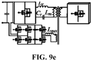
- Figs. 9a to 9e illustrate schematic diagrams of five topological structures of a bidirectional DC converter in a charging apparatus according to the present application.
- Fig. 9a illustrates an LLC resonant DC converter
- Fig. 9b illustrates a dual-active-bridge (DAB) DC converter
- Fig. 9c illustrates a CLLC resonant DC converter
- Fig. 9d illustrates a current-fed dual-active-bridge (CF-DAB) DC converter
- Fig. 9e illustrates a partial power converter (PPC).
- the bidirectional DC converter in the charging apparatus of the present application may employ the topological structures exemplified in Figs. 9a to 9e and various variants of these topological structures capable of achieving the functions described above.
- Figs. 10a and 10b illustrate schematic diagrams of the structure of a bidirectional DC converter in a charging apparatus according to the present application.
- Fig. 10a illustrates a two-stage LLC-type bidirectional DC converter 1000a, where the bus side of the DC converter is used to connect to the DC source 102, and the capacitor Cdc on the bus side is connected to a Buck-Boost circuit, and the back end of this Buck-Boost circuit is connected to a bidirectional LLC series resonant converter (LLC-SRC), and the bidirectional LLC-SRC is then connected to the battery BT1.
- LLC-SRC bidirectional LLC series resonant converter
- the two-stage LLC-type bidirectional DC converter has two stages of voltage control, where the Buck-Boost circuit can control the duty cycles of the switch modules S1 and S2 to achieve boost or buck as needed, and the bidirectional LLC-SRC achieves further voltage control to ensure a constant voltage supplied to the battery.
- the bidirectional LLC-SRC adopts frequency control, and for each bridge arm thereof, the duty cycles of the upper and lower switch modules M1-M8 are all 50%, and when the system load changes, the operating frequency of the system needs to be changed. Specifically, when the load increases, the switching frequency of the switch modules M1-M8 is reduced, and when the load decreases, the switching frequency of the switch modules M1-M8 is increased.
- the LLC circuit in the bidirectional LLC-SRC includes a capacitor Cr as well as inductors Lr and Lm, where the capacitor Cr and the inductor Lr are regarded as one part and their impedance is set to Zr, and the inductor Lm is regarded as the other part and its impedance is set to Zo; when the system load changes, the switching frequency of the switch modules M1-M4 is changed, and the voltage division ratio of Zr and Zo can be changed to make the output voltage stable.
- the main controller 108 controls the switch modules M5 and M8 to be closed and M6 and M7 to be opened, so that the battery BT1 stores energy into the secondary winding of the transformer of the bidirectional LLC-SRC; then at time t2, the main controller 108 controls the switch modules M5 and M8 to be opened and M6 and M7 to be closed, so that the secondary winding of the transformer is discharged to the battery BT1; at time t3, the state of the switch modules at time t2 is maintained, and the battery BT1 stores energy into the secondary winding of the transformer again; and at time t4, the main controller 108 controls the switch modules M5 and M8 to be closed and M6 and M7 to be opened, so that the secondary winding is discharged to the battery BT1.
- bidirectional LLC-SRC can employ other control strategies that are suitable for generating pulse currents to heat the battery.
- Fig. 10b illustrates a dual-active-bridge DC converter 1000b, which includes a U1-side full-bridge circuit, an inductor L1, a transformer T, and a U2-side full-bridge circuit.
- the DC bus of the U1-side full-bridge circuit is connected to the DC source 102
- the inductor L1 and the primary winding of the transformer T are connected in series between the midpoints of the two bridge arms of the U1-side full-bridge circuit
- the secondary winding of the transformer T is connected between the midpoints of the two bridge arms of the U2-side full-bridge circuit
- the DC bus of the U2-side full-bridge circuit is connected to the battery BT1.
- Figs. 11a to 11c illustrate waveform diagrams of different modulation strategies of the bidirectional DC converter 1000b of Fig. 10b .
- Fig. 11a illustrates a waveform diagram of a dual-phase-shifting (DPS) modulation strategy of a dual-active-bridge DC converter
- Fig. 11b illustrates a waveform diagram of an extended-phase-shifting (EPS) modulation strategy of a dual-active-bridge DC converter
- Fig. 11c illustrates a waveform diagram of triple-phase-shifting (TPS) modulation strategy of a dual-active-bridge DC converter.
- DPS dual-phase-shifting
- EPS extended-phase-shifting
- TPS triple-phase-shifting
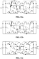
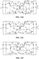
- the operation mode of the dual-active-bridge DC converter 1000b of Fig. 10b can be classified into 8 operation states of Figs. 12a to 12h .
- Mode 1 is as shown in Fig. 12a .
- switches S1 and S4 are opened and S2 and S3 are closed, and the current iL on the inductor L1 is negative; at the time t0, switches S1 to S4 are closed and S2 and S3 remain closed, and VP is 0, and since the current iL is still negative, the current is renewed through the switch S3 and the diode D1 or through the switch S2 and the diode D4; and in the U2-side full-bridge circuit, the switches Q1 and Q4 are opened and Q2 and Q3 are closed, and since the current iL is negative, the current on the U2 side feeds energy to the battery BT1 through diodes M2 and M3 and the current iL gradually decreases.
- Mode 2 is as shown in Fig. 12b .
- the current iL is still less than 0, switches S2 and S3 are opened and S1 and S4 remain closed, and the current iL changes to be renewed via diodes D1 and D4, with Vp being equal to U1; and the switching state of the U2-side full-bridge circuit is the same as in mode 1, and the inductor L1 feeds energy to the battery BT1 on the U2 side as well as to the U1 side at the same time, until the current iL drops to zero at the time t1'.
- Mode 3 is as shown in Fig. 12c .
- the current iL changes from negative to positive
- the switches S1 and S4 and Q2 and Q3 are closed and the current flows through these four switches, the DC source on the U1 side and the battery BT1 on the U2 side feed energy to the inductor L1 at the same time, so that the current iL increases rapidly.
- Mode 4 is as shown in Fig. 12d .
- the switches Q1 and Q4 are closed and Q2 and Q3 remain closed, VS is 0, and the current on the U2 side is renewed through the switch Q2 and the diode M4 or through the switch Q3 and the diode M1; and the current iL is positive, the switching state of the U1-side full-bridge circuit is the same as in mode 3, and the DC source on the U1 side feeds energy to the inductor L1, so that the current iL increases and the gradient decreases.
- Mode 5 is as shown in Fig. 12e .
- the switches Q2 and Q3 are opened and Q1 and Q4 remain closed, VS is equal to U2, and since the current iL is positive, the current on the U2 side provides energy to the battery BT1 through the diodes M1 and M4; and the switching state of the U1-side full-bridge circuit is the same as in mode 3, and the DC source on the U1 side feeds energy to the inductor L1, and the current iL increases or decreases according to the energy difference between the energy received from the U1 side and the energy supplied to battery BT1.
- Mode 6 is as shown in Fig. 12f .
- switches S1 and S4 are opened and S2 and S3 remain opened, the current iL is positive and changes to be renewed through diodes D2 and D3, the inductor L1 feeds energy to the DC source on the U1 side, the switching state of the U2-side full-bridge circuit is the same as in mode 5, the current on the U2 side feeds energy to the battery BT1 through diodes M1 and M4, so that the current iL decreases; and at time t5, the switches S2 and S3 are closed and S1 and S4 remain opened, the current iL is still renewed through diodes D2 and D3, the inductor L1 feeds energy to the DC source on the U1 side and the battery BT1 at the same time, and the current iL decreases until the current iL drops to zero at time t5'.
- Mode 7 is as shown in Fig. 12g .
- the current iL changes from positive to negative
- the switches S2 and S3 and Q1 and Q4 are closed and the current flows through these four switches, the DC source on the U1 side and the battery BT1 on the U2 side feed energy to the inductor L1 at the same time, so that the current iL increases rapidly.
- Mode 8 is as shown in Fig. 12h .
- switches Q1 and Q4 are opened and Q2 and Q3 remain opened, and since the current iL is negative, the current on the U2 side feeds energy to the battery BT1 through diodes M2 and M3; the switching state of the U1-side full-bridge circuit is the same as in mode 7, and the DC source on the U1 side feeds energy to the inductor L1, and the current iL increases and the gradient decreases; and at time t7, switches Q2 and Q3 are closed and Q1 and Q4 remain opened, and the current on the U2 side still feeds energy to the battery BT1 through diodes M2 and M3.
- the heating pulse cycle may start in mode 3 or mode 7.
- the waveform of the heating pulse current for the battery BT1 can be adjusted by adjusting the phase shift ratios of the U1-side full-bridge circuit and the U2-side full-bridge circuit and the voltage of the DC source on the U1 side.
- the person skilled in the art can also infer the operation modes of the extended-phase-shifting modulation strategy and the triple-phase-shifting modulation strategy based on the waveforms of FIG. 11b and FIG. 11c , which will not be repeated here. It should be understood that in addition to the modulation strategies exemplified in Figs. 11a to 11c , the dual-active-bridge DC converter 1000b may employ other control strategies suitable for generating pulse currents to heat the battery.
Landscapes
- Engineering & Computer Science (AREA)
- Manufacturing & Machinery (AREA)
- Chemical & Material Sciences (AREA)
- Chemical Kinetics & Catalysis (AREA)
- Electrochemistry (AREA)
- General Chemical & Material Sciences (AREA)
- Power Engineering (AREA)
- Automation & Control Theory (AREA)
- Secondary Cells (AREA)
- Physics & Mathematics (AREA)
- Electromagnetism (AREA)
- Charge And Discharge Circuits For Batteries Or The Like (AREA)
Abstract
Description
- The present invention relates to the technical field of batteries, and in particular, to a charging apparatus and a method for heating a battery.
- With the development of new energy technologies, more and more fields use batteries as power. Due to the advantages of high energy density, recyclable charging, safety and environmental protection, batteries are widely applied in the fields of new energy vehicles, consumer electronics, energy storage systems, and the like.
- However, the use of batteries in low-temperature environments may be limited to a certain extent. Specifically, in a low-temperature environment, the charging and discharging capacity of a battery will be seriously attenuated, and charging and discharging the battery will also lead to the life attenuation in the whole life cycle, and charging the battery may even lead to irreversible damage to the battery. Therefore, in order to enable the normal use of a battery, it is necessary to heat the battery in a low-temperature environment.
- In view of the aforementioned problems, the present application proposes a charging apparatus and a method for heating a battery to solve the problem that restricted use of batteries in a low-temperature environment.
- To this end, a first aspect of the present invention provides a charging apparatus, the charging apparatus including:
- a direct current (DC) source;
- a bidirectional DC converter connected between the aforementioned DC source and a charging port of the charging apparatus;
- a pulse heating module connected in parallel with the aforementioned bidirectional DC converter; and
- a controller configured for:
selecting, when a heating request is received and according to a heating frequency requirement of a battery, one of the aforementioned pulse heating module and the aforementioned bidirectional DC converter to heat the battery. - In embodiments of the present application, the charging apparatus is used to heat a low-temperature battery, which can eliminate the need for an in-vehicle battery heating apparatus, thus realizing the pulse rapid heating function of the vehicle at a low temperature without increasing the cost of the vehicle. In addition, in embodiments of the present application, different heating apparatuses are selected according to the heating frequency requirement of the battery to heat the battery at different frequencies, thus enabling the charging apparatus to be applicable to heating various types of batteries.
- In some embodiments, the controller is configured for:
- when the aforementioned heating frequency requirement is less than a preset first frequency, selecting the aforementioned bidirectional DC converter to heat the battery; and
- when the aforementioned heating frequency requirement is greater than or equal to the preset first frequency, selecting the aforementioned pulse heating module to heat the battery.
- In embodiments of the present application, pulse heating for the low frequency range is achieved by a bidirectional DC converter, and pulse heating for the high frequency range is achieved by a pulse heating module, thus enabling the charging apparatus to cover the pulse waveform of the full frequency range. In some embodiments of the present application, the preset first frequency is 100 Hz. In addition, in some embodiments of the present application, the maximum frequency to which the aforementioned pulse heating module can be applied is 2 kHz.
- In some embodiments, the controller is configured for: when heating of the battery is started, controlling the aforementioned bidirectional DC converter or the aforementioned pulse heating module so that the battery is discharged during the first half of the first cycle of the pulse current for heating the battery.
- In embodiments of the present application, by controlling the battery to discharge during the first half of the first cycle, the battery is prevented from lithium plating due to charging at ultra-low temperatures. It should be understood that certain low-temperature battery cells also allow for charging for short periods of time, so in some other embodiments of the present application, the controller may be configured for: when heating of the battery is started, controlling the aforementioned bidirectional DC converter or the aforementioned pulse heating module so that the battery is charged during the first half of the first cycle of the pulse current for heating the battery.
- In some embodiments, the controller is configured for: when the heating frequency requirement is less than a preset second frequency, controlling the aforementioned bidirectional DC converter so that energy released by the battery is fed back to the aforementioned DC source during battery discharging, wherein the preset second frequency is less than the preset first frequency.
- In embodiments of the present application, because of the use of the bidirectional DC converter, it is possible to feed the electrical energy back to the DC source without storing the energy in the energy storage element of the DC converter, which reduces the requirement for the energy storage element in the DC converter as well as the switching devices.
- In some embodiments, the aforementioned DC source includes a bidirectional rectifier connected to the power grid, and the controller is configured for: when the heating frequency requirement is less than a preset second frequency, controlling the aforementioned rectifier and the aforementioned bidirectional DC converter so that energy released by the battery is fed back to the power grid during battery discharging, wherein the preset second frequency is less than the preset first frequency.
- In embodiments of the present application, because of the use of the bidirectional rectifier, the electrical energy can be fed back to the power grid; specifically, when the pulse heating current is generated using the bidirectional DC converter, if the pulse frequency is low, the energy is fed back to the power grid through the bidirectional rectifier instead of being stored in the energy storage element of the DC converter, thereby reducing the requirement for the energy storage elements in the rectifier and in the DC converter as well as the switching devices.
- In some other embodiments, the above DC source includes an energy storage apparatus. In embodiments of the present application, since the DC source includes an energy storage apparatus, energy may be fed back into the energy storage apparatus for storage when the pulse frequency is low; furthermore, the energy supplied to the battery to be heated may come from the energy storage apparatus without the involvement of a rectifier connected to the power grid. In some specific embodiments of the present application, the aforementioned energy storage apparatus may include an energy storage battery and/or a super-capacitor.
- In some embodiments, the controller is configured for: when the heating frequency requirement is greater than or equal to a preset second frequency and less than the preset first frequency, controlling the aforementioned bidirectional DC converter so that energy released by the battery is stored in an energy storage element of the aforementioned bidirectional DC converter during battery discharging, wherein the preset second frequency is less than the preset first frequency.
- In some embodiments, the aforementioned DC source includes a rectifier connected to the power grid, the aforementioned charging apparatus is configured for monitoring the voltage of the battery, and the controller is configured for:
when the voltage of the battery is lower than a preset voltage threshold for an initial voltage of the battery, controlling the aforementioned rectifier to recharge the battery, wherein this initial voltage is a voltage when the battery starts to be heated. - In embodiments of the present application, the battery is recharged by a rectifier, making it possible to heat the battery by the pulse current even when the voltage of the battery is low, without resulting in a situation where the battery cannot be heated when the state of charge is low.
- In some specific embodiments, when the battery is heated by the aforementioned bidirectional DC converter, the controller is configured for controlling the aforementioned rectifier and the aforementioned bidirectional DC converter to adjust the balance between charging energy and discharging energy for pulse heating of the battery.
- In embodiments of the present application, by adjusting the balance between charging energy and discharging energy, it is ensured that the energy stored in the battery does not decrease and the state of charge of the battery does not decrease.
- In some specific embodiments, when the battery is heated by the aforementioned pulse heating module, the controller is configured for controlling the aforementioned rectifier so that an output voltage of the aforementioned rectifier is equal to a preset voltage value during charging of the battery by an energy storage element of the aforementioned pulse heating module, the preset voltage value being greater than or equal to the initial voltage of the battery.
- In embodiments of the present application, the output voltage of the rectifier is controlled to be greater than or equal to the initial voltage of the battery during charging of the battery, so that during charging, the battery can be replenished with the energy released and consumed, and the battery can reach energy balance during pulse charging and discharging, thus maintaining the voltage of the battery at the initial voltage.
- In an embodiment of the present application, the preset voltage value is slightly greater than the initial voltage of the battery.
- In some embodiments, the charging apparatus includes a plurality of bidirectional DC converters connected in parallel with each other, and when the heating frequency requirement is less than the preset first frequency, the battery is heated by one or more of the aforementioned plurality of bidirectional DC converters.
- In some embodiments, the charging apparatus includes a plurality of pulse heating modules connected in parallel with each other, and when the heating frequency requirement is greater than or equal to the preset first frequency, the battery is heated by one or more of the aforementioned plurality of pulse heating modules.
- A second aspect of the present invention provides a method for heating a battery, the method including:
- receiving a heating request as well as a heating frequency requirement of a battery; and
- in response to the heating request and according to the heating frequency requirement, selecting one of a pulse heating module and a bidirectional DC converter connected between a DC source and the battery to heat the battery.
- In embodiments of the present application, different heating apparatuses are selected according to the heating frequency requirement of the battery to heat the battery at different frequencies, thus enabling it to be applicable to heating various types of batteries.
- In some embodiments, the method includes:
- when the heating frequency requirement is less than a preset first frequency, heating the battery by the aforementioned bidirectional DC converter; and
- when the heating frequency requirement is greater than or equal to the preset first frequency, heating the battery by the aforementioned pulse heating module.
- In embodiments of the present application, pulse heating for the low frequency range is achieved by a bidirectional DC converter, and pulse heating for the high frequency range is achieved by a pulse heating module, thus enabling it to cover the pulse waveform of the full frequency range. In some embodiments of the present application, the preset first frequency is 100 Hz. In addition, in some embodiments of the present application, the maximum frequency to which the aforementioned pulse heating module can be applied is 2 kHz.
- In some embodiments, the method includes:
when heating of the battery is started, controlling the aforementioned bidirectional DC converter or the aforementioned pulse heating module so that the battery is discharged during the first half of the first cycle of the pulse current for heating the battery. - In embodiments of the present application, by controlling the battery to discharge during the first half of the first cycle, the battery is prevented from lithium plating due to charging at ultra-low temperatures. It should be understood that certain low-temperature battery cells also allow for charging for short periods of time, so in some other embodiments of the present application, the controller may be configured for: when heating of the battery is started, controlling the aforementioned bidirectional DC converter or the aforementioned pulse heating module so that the battery is charged during the first half of the first cycle of the pulse current for heating the battery.
- In some embodiments, the method includes:
when the heating frequency requirement is less than a preset second frequency, controlling the aforementioned bidirectional DC converter so that energy released by the battery is fed back to the aforementioned DC source during battery discharging, wherein the preset second frequency is less than the preset first frequency. - In embodiments of the present application, because of the use of the bidirectional DC converter, it is possible to feed the electrical energy back to the DC source without storing the energy in the energy storage element of the DC converter, which reduces the requirement for the energy storage element in the DC converter as well as the switching devices.
- In some embodiments, the aforementioned DC source includes a bidirectional rectifier connected to the power grid, the method including:
when the heating frequency requirement is less than a preset second frequency, controlling the aforementioned bidirectional rectifier and the aforementioned bidirectional DC converter so that energy released by the battery is fed back to the power grid during battery discharging, wherein the preset second frequency is less than the preset first frequency. - In some embodiments, the above DC source includes an energy storage apparatus. In embodiments of the present application, since the DC source includes an energy storage apparatus, energy may be fed back into the energy storage apparatus for storage when the pulse frequency is low; furthermore, the energy supplied to the battery to be heated may come from the energy storage apparatus without the involvement of a rectifier connected to the power grid. In some specific embodiments of the present application, the aforementioned energy storage apparatus may include an energy storage battery and/or a super-capacitor.
- In some embodiments, the method includes:
when the heating frequency requirement is greater than or equal to a preset second frequency and less than the preset first frequency, controlling the aforementioned bidirectional DC converter so that energy released by the battery is stored in an energy storage element of the aforementioned bidirectional DC converter during battery discharging, wherein the preset second frequency is less than the preset first frequency. - In some embodiments, the aforementioned DC source includes a rectifier connected to the power grid, the method including:
- monitoring the voltage of the battery; and
- when the voltage of the battery is lower than a preset voltage threshold for an initial voltage of the battery, controlling the aforementioned rectifier to recharge the battery, wherein this initial voltage is a voltage when the battery starts to be heated.
- In embodiments of the present application, the battery is recharged by a rectifier, making it possible to heat the battery by the pulse current even when the voltage of the battery is low, without resulting in a situation where the battery cannot be heated when the state of charge is low.
- In some embodiments, the method includes:
when the battery is heated by the aforementioned bidirectional DC converter, controlling the aforementioned rectifier and the aforementioned bidirectional DC converter to adjust the balance between charging energy and discharging energy for pulse heating of the battery. - In some embodiments, the method includes:
when the battery is heated by the aforementioned pulse heating module, controlling the aforementioned rectifier so that an output voltage of the aforementioned rectifier is equal to a preset voltage value during charging of the battery by an energy storage element of the aforementioned pulse heating module, the preset voltage value being greater than or equal to the initial voltage of the battery. - In some embodiments, a plurality of bidirectional DC converters connected in parallel with each other are connected between the aforementioned DC source and the battery, and when the heating frequency requirement is less than the preset first frequency, the battery is heated by one or more of the aforementioned plurality of bidirectional DC converters.
- In some embodiments, a plurality of pulse heating modules connected in parallel with each other are connected between the aforementioned DC source and the battery, and when the heating frequency requirement is greater than or equal to the preset first frequency, the battery is heated by one or more of the aforementioned plurality of pulse heating modules.
- A third aspect of the present application provides a storage medium storing instructions which, when executed by a computing device, cause the aforementioned processor to implement the method for heating a battery as in the second aspect of the present application.
- In order to illustrate the technical solutions of the present application more clearly, a brief introduction will be given below of the drawings that are required to be used in the examples of the present application. It is apparent that the drawings described below are only some embodiments of the present application, and for those of ordinary skill in the art, according to the drawings, other drawings can also be obtained without involving any creative efforts. In the accompanying drawings:
-
Fig. 1 illustrates a block diagram of acharging apparatus 100 according to an embodiment of the present application; -
Fig. 2 illustrates a flowchart of amethod 200 for heating a battery according to an embodiment of the present application; -
Fig. 3 illustrates a block diagram of acharging apparatus 300 according to an embodiment of the present application; -
Fig. 4 illustrates a block diagram of acharging apparatus 400 according to another embodiment of the present application; -
Fig. 5 illustrates a flowchart of amethod 500 for heating a battery according to another embodiment of the present application; -
Fig. 6 illustrates a block diagram of acharging apparatus 600 according to another embodiment of the present application; -
Fig. 7 illustrates a block diagram of acharging apparatus 700 according to yet another embodiment of the present application; -
Fig. 8 illustrates a flowchart of abattery charging method 800 according to an embodiment of the present application; -
Figs. 9a to 9e illustrate schematic diagrams of topological structures of a bidirectional DC converter in a charging apparatus according to the present application; -
Figs. 10a and 10b illustrate schematic diagrams of the structure of a bidirectional DC converter in a charging apparatus according to the present application; -
Figs. 11a to 11c illustrate waveform diagrams of different modulation strategies of the bidirectional DC converter ofFig. 10b ; and -
Figs. 12a to 12h illustrate the operation modes of the bidirectional DC converter ofFig. 10b under the modulation strategy ofFig. 11a . - Embodiments of the present application will be described in detail below in conjunction with the drawings. The following embodiments are only used to more clearly illustrate the technical solution of the present application, and therefore are only used as examples and cannot be used to limit the scope of protection of the present application.
- Unless otherwise defined, all technical and scientific terms used herein have the same meaning as commonly understood by those skilled in the art belonging to the technical field of the present application; the terms used herein are intended only for the purpose of describing specific embodiments and are not intended to limit the present application; the terms "including" and "having" and any variations thereof in the specification and the claims of the present application and in the description of drawings above are intended to cover non-exclusive inclusion.
- In the description of the embodiments of the present application, the technical terms "first" and "second", and the like are used only to distinguish between different objects, and are not to be understood as indicating or implying a relative importance or implicitly specifying the number, particular order, or primary and secondary relation of the technical features indicated, unless otherwise specified.
- Reference herein to "embodiment" means that particular features, structures, or characteristics described in connection with the embodiment can be included in at least one embodiment of the present application. The appearance of this phrase in various places in the specification does not necessarily refer to the same embodiment, nor is it a separate or alternative embodiment that is mutually exclusive with other embodiments. It is explicitly and implicitly understood by those skilled in the art that the embodiments described herein may be combined with other embodiments.
- In the description of the embodiments of the present application, the term "and/or" is simply a description of an association of associated objects, which indicates that there may exist three relationships, for example, A and/or B may mean: the presence of A, the presence of both A and B, and the presence of B. In addition, the character "/" herein generally means that the associated objects before and after it are in an "or" relationship.
- In the description of the embodiments of the present application, the term "a plurality of" refers to more than two (including two), unless otherwise expressly defined. In the description of the embodiments of the present application, unless otherwise expressly specified and limited, the technical terms "connected", "connection", etc., should be understood in a broad sense, for example, it may be a mechanical connection, or an electrical connection; it may be a direct connection, an indirect connection through an intermediate medium, an internal connection of two elements, or interaction between two elements. For those of ordinary skill in the art, the specific meanings of the above terms in the embodiments of the present application can be understood according to specific situations.
- If steps are stated sequentially in this specification or claims, it does not necessarily mean that the embodiments or aspects are limited to the order in which they are stated. On the contrary, it is conceivable to also perform the steps in a different order or in parallel with each other, unless one step builds on another, which absolutely requires that the built step be performed subsequently (this will however become clear in individual cases). Therefore, the stated order may be the preferred embodiment.
- At present, the batteries are used in energy storage power source systems such as hydraulic, thermal, wind and solar power stations as well as in electric vehicles such as electric bicycles, electric motorcycles and electric cars, and military equipment and aerospace fields. With continuous expansion of the application fields of batteries, the market demand is also constantly expanding.
- The inventors of the present application have found, after research, that in-vehicle rapid heating solutions require additional costs for the vehicle and that in-vehicle rapid heating apparatuses are often only applicable to specific models. Different types of models may have different types of batteries, and different types of batteries may have different internal resistances and thus need to be heated with pulse currents of different frequencies and amplitudes, otherwise the batteries may suffer from lithium plating because lithium ions are too quickly deintercalated from the positive electrode but not embedded into the negative electrode in equal amounts.
- In addition, the inventors of the present application have found that, when the power level of the battery is low, the remaining energy in the battery is not sufficient to heat the battery to a temperature at which it can be used. In addition, when the battery needs to be charged in a low-temperature environment, the user often needs to wait for a long time in the low-temperature environment until the battery is heated up to a temperature at which it can be charged, resulting in a very poor user experience.
- Based on the above findings, in order to reduce the cost of the electrical apparatus loaded with the battery and to achieve rapid heating of the battery when the residual energy is low, the inventors have designed a charging apparatus which, by integrating the low-temperature rapid heating technology for batteries, can eliminate the rapid heating apparatus on the electrical apparatus side and select different apparatuses to generate pulse heating currents according to the heating frequency requirement of the battery so as to adapt to different types of batteries.
-
Fig. 1 illustrates a block diagram of acharging apparatus 100 according to an embodiment of the present application. As shown inFig. 1 , the chargingapparatus 100 includes aDC source 102, apulse heating module 104, abidirectional DC converter 106 and amain controller 108. Thepulse heating module 104 and thebidirectional DC converter 106 are connected between theDC source 102 and chargingports apparatus 100, and thepulse heating module 104 and thebidirectional DC converter 106 are connected in parallel with each other. The chargingports apparatus 100 are used to connect with a battery BT1. Themain controller 108 controls the operation of theDC source 102, thepulse heating module 104, and thebidirectional DC converter 106. - The embodiment of
Fig. 1 is further described below with reference toFig. 2. Fig. 2 illustrates a flowchart of amethod 200 for heating a battery according to an embodiment of the present application. As shown inFig. 2 , atstep 202, a heating request as well as a heating frequency requirement of the battery BT1 are received. Then, in response to the heating request and according to the heating frequency requirement, one of thepulse heating module 104 and thebidirectional DC converter 106 connected between theDC source 102 and the battery BT1 is selected to heat the battery BT1,step 204. - In embodiments of the present application, the charging apparatus is used to heat a low-temperature battery, which can eliminate the need for an in-vehicle battery heating apparatus, thus realizing the pulse rapid heating function of the vehicle at a low temperature without increasing the cost of the vehicle. In addition, in embodiments of the present application, different heating apparatuses are selected according to the heating frequency requirement of the battery to heat the battery at different frequencies, thus enabling the charging apparatus to be applicable to heating various types of batteries, that is, applicable to various types of vehicles.
-
Fig. 3 illustrates a block diagram of acharging apparatus 300 according to an embodiment of the present application. As shown inFig. 3 , theDC source 102 includes arectifier 1021. The AC side of therectifier 1021 is used to connect to the power grid, and the DC side of therectifier 1021 is connected to thepulse heating module 104 and thebidirectional DC converter 106. -
Fig. 4 illustrates a block diagram of acharging apparatus 400 according to another embodiment of the present application. As shown inFig. 4 , theDC source 102 includes arectifier 1021 and anenergy storage apparatus 1022. The AC side of therectifier 1021 is used to connect to the power grid, and the DC side of therectifier 1021 is connected to theenergy storage apparatus 1022, thepulse heating module 104, and thebidirectional DC converter 106. In this way, energy can be supplied to the battery BT1 by theenergy storage apparatus 1022, or energy can be supplied to the battery BT1 by the power grid through therectifier 1021. It should be understood thatFig. 4 is an exemplary embodiment of the present application, and in other embodiments of the present application, theDC source 102 may include only theenergy storage apparatus 1022 or only theenergy storage apparatus 1022. In some embodiments, theenergy storage apparatus 1022 may include an energy storage battery and/or a super-capacitor. -
Fig. 5 illustrates a flowchart of amethod 500 for heating a battery according to another embodiment of the present application. As shown inFig. 5 , atstep 502, a heating request as well as a heating frequency requirement of the battery BT1 are received. Then, atstep 504, it is judged whether the heating frequency requirement is greater than or equal to the preset first frequency. In some embodiments of the present application, the preset first frequency is 100 Hz. If the heating frequency requirement is greater than or equal to the preset first frequency, the flow proceeds to step 506 in which the battery BT1 is heated by thepulse heating module 104. - In some embodiments of the present application, when heating of the battery BT1 is started, the
main controller 108 controls thepulse heating module 104 so that the battery BT1 is discharged during the first half of the first cycle of the pulse current for heating the battery BT1. The reason for such setting is that the inventors of the present application have observed the movement pattern of lithium ions in practice and found that at lower temperatures, there is not enough lithium intercalation space in the negative electrode of the battery, and if the battery is charged at this moment, the phenomenon of lithium plating may be caused. The inventors of the present application have also found that certain low-temperature battery cells also allow for charging for short periods of time, so in some other embodiments of the present application, when heating of the battery BT1 is started, themain controller 108 can control thepulse heating module 104 so that the battery BT1 is charged during the first half of the first cycle of the pulse current for heating the battery BT1. - During the heating of the battery BT1 by the
pulse heating module 104, the voltage of the battery BT1 is monitored,step 508. Atstep 510, it is judged whether the voltage of the battery BT1 is lower than a preset voltage threshold of an initial voltage. If the voltage of the battery BT1 is lower than the preset voltage threshold of the initial voltage, an output voltage of therectifier 1021 is controlled to be equal to a preset voltage value during charging of the battery BT1 by an energy storage element of thepulse heating module 104,step 512, the preset voltage value being greater than or equal to the initial voltage of the battery BT1. If the voltage of the battery BT1 is not lower than the preset voltage threshold of the initial voltage, the flow returns to step 508 to continue monitoring the voltage of the battery BT1. In some embodiments of the present application, this preset voltage value is slightly greater than the initial voltage of the battery BT1. In embodiments of the present application, the output voltage of therectifier 1021 is controlled to be greater than or equal to the initial voltage of the battery BT1 during charging of the battery BT1, so that during charging, the battery BT1 can be replenished with the energy released and consumed, and the battery BT1 can reach energy balance during pulse charging and discharging, thus maintaining the voltage of the battery BT1 at the initial voltage. - If it is judged at
step 504 that the heating frequency requirement is less than the preset first frequency, the flow proceeds to step 514 in which the battery BT1 is heated by theDC converter 106. In some embodiments of the present application, when heating of the battery BT1 is started, themain controller 108 controls theDC converter 106 so that the battery BT1 is discharged during the first half of the first cycle of the pulse current for heating the battery BT1. Because certain low-temperature battery cells also allow for charging for short periods of time, so in some other embodiments of the present application, when heating of the battery BT1 is started, themain controller 108 can control theDC converter 106 so that the battery BT1 is charged during the first half of the first cycle of the pulse current for heating the battery BT1. - In the case where the battery BT1 is heated by the
DC converter 106, it is judged whether the heating frequency requirement is less than a preset second frequency,step 516. In some embodiments of the present application, the preset second frequency is 50 Hz; and it should be understood that the preset second frequency can be set to other frequency values according to actual needs. In some embodiments of the present application, therectifier 1021 is a bidirectional rectifier, that is, thebidirectional rectifier 1021 can not only rectify the alternating current at the power grid side into direct current, but also reverse the direct current into alternating current and feed it back to the power grid. If the heating frequency requirement is less than the preset second frequency, themain controller 108 controls theDC converter 106 and thebidirectional rectifier 1021 to feedback energy released by the battery BT1 to the power grid during battery discharging,step 518. It should be understood that in some embodiments including theenergy storage apparatus 1022, if the heating frequency requirement is less than the preset second frequency, pulse energy can be exchanged between theenergy storage apparatus 1022 and the battery BT1 to heat the battery BT1. Specifically, theDC converter 106 is controlled to feed back energy released by the battery BT1 to theenergy storage apparatus 1022 during battery discharging. If the heating frequency requirement is greater than or equal to the preset second frequency, themain controller 108 controls theDC converter 106 and therectifier 1021 to store energy released by the battery BT1 in an energy storage element of theDC converter 106 during battery discharging,step 520. - During the heating of the battery BT1 by the
DC converter 106, the voltage of the battery BT1 is monitored,step 522. Atstep 524, it is judged whether the voltage of the battery BT1 is lower than a preset voltage threshold of an initial voltage. If the voltage of the battery BT1 is lower than the preset voltage threshold of the initial voltage, themain controller 108 controls theDC converter 106 and therectifier 1021 to adjust the balance between charging energy and discharging energy for pulse heating of the battery BT1,step 526. If the voltage of the battery BT1 is not lower than the preset voltage threshold of the initial voltage, the flow returns to step 522 to continue monitoring the voltage of the battery BT1. In some embodiments of the present application, this preset voltage value is slightly greater than the initial voltage of the battery BT1. -
Fig. 6 illustrates a block diagram of acharging apparatus 600 according to another embodiment of the present application. As shown inFig. 6 , thepulse heating module 104 has four switch modules Q1-Q4, an inductor L, and a switch K1. The switch K1 is arranged on the positive bus of the input side of thepulse heating module 104, the switch modules Q1 and Q3 are connected in series between the positive bus and the negative bus of thepulse heating module 104, and the switch modules Q2 and Q4 are also connected in series between the positive bus and the negative bus of thepulse heating module 104, and the inductor L is connected between the connection midpoint of the switch modules Q1 and Q3 and the connection midpoint of the switch modules Q2 and Q4. In addition, the positive bus of theDC converter 106 is connected to the positive bus of theDC source 102 via a switch K2. - If it is judged at
step 504 that the heating frequency requirement is greater than or equal to the preset first frequency, themain controller 108 controls the switch K1 to be closed and the switch K2 to be opened, so that the battery BT1 is heated by thepulse heating module 104. If it is judged atstep 504 that the heating frequency requirement is less than the preset first frequency, themain controller 108 controls the switch K1 to be opened and the switch K2 to be closed, so that the battery BT1 is heated by theDC converter 106. - It should be understood that
FIG. 6 illustrates an example embodiment of the present application. In other embodiments of the present application, the positive bus of theDC converter 106 is directly connected to the positive bus of theDC source 102 without passing through the switch K2, and when the heating frequency requirement is greater than or equal to the preset first frequency, themain controller 108 controls the switch K1 to be closed and all the switch modules in theDC converter 106 to be opened; and when the heating frequency requirement is less than the preset first frequency, themain controller 108 controls the switch K1 to be opened and controls the closing and opening of the switch modules in theDC converter 106 to heat the battery BT1. - During the heating of the battery BT1 by the
pulse heating module 104, at time t1, themain controller 108 controls the switch modules Q1 and Q4 to be closed and Q2 and Q3 to be opened, so that the battery BT1 stores energy into the inductor L; then at time t2, themain controller 108 controls the switch modules Q1 and Q4 to be opened and Q2 and Q3 to be closed, so that the inductor L is discharged to the battery BT1; at time t3, the state of the switch modules at time t2 is maintained, and the battery BT1 stores energy into the inductor L again; and at time t4, themain controller 108 controls the switch modules Q1 and Q4 to be closed and Q2 and Q3 to be opened, so that the inductor L is discharged to the battery BT1. It should be understood that the pulse heating cycle may also start at time t3, travel through times t4 and 11, and end at time t2. In the embodiments of the present application, during the first cycle of generating the pulse current, the first half cycle must first start with the storage of energy by the battery BT1 to the inductor L, i.e., starting at time t1 or t3. - It should be understood that
FIG. 6 illustrates an example embodiment of the present application. In addition to the topological structure illustrated inFIG. 6 , thepulse heating module 104 may employ any other topological structures capable of implementing the pulse heating function. -
Fig. 7 illustrates a block diagram of acharging apparatus 700 according to an embodiment of the present application. As shown inFIG. 7 , the chargingapparatus 500 includes a plurality ofpulse heating modules 1041, 1042, ..., and 104m connected in parallel with each other, and when the heating frequency requirement is greater than or equal to the preset first frequency, the battery BT1 is heated by one or more of the plurality ofpulse heating modules 1041, 1042, ..., and 104m. In addition, the chargingapparatus 700 includes a plurality ofDC converters 1061, 1062, ..., and 106n connected in parallel with each other, and when the heating frequency requirement is less than the preset first frequency, the battery BT1 is heated by one or more of the plurality ofDC converters 1061, 1062, ..., and 106n. In addition, the battery BT1 may be charged by one or more of the plurality ofDC converters 1061, 1062, ..., and 106n. -
Fig. 8 illustrates a flowchart of abattery charging method 800 according to an embodiment of the present application. As shown inFig. 8 , atstep 802, a first message is received, the first message containing a heating request, a heating frequency requirement, a heating current limit, and the like. Then, atstep 804, it is judged whether the received heating frequency requirement is greater than or equal to the preset first frequency. If the heating frequency requirement is greater than or equal to the preset first frequency, the battery BT1 is heated by thepulse heating module 104,step 806. If the heating frequency requirement is less than the preset first frequency, the battery BT1 is heated by theDC converter 106,step 808. Then, atstep 810, a second message is received, the second message containing a heating stop instruction. In response to the heating stop instruction, atstep 812, the heating of the battery BT1 is stopped. Atstep 814, a third message is received, the third message containing a charging instruction, a DC charging voltage limit, a current limit, and the like. In response to the charging instruction, atstep 816, themain controller 108 controls theDC source 102 and theDC converter 106 to charge the battery BT1 according to the DC charging voltage limit and current limit. Finally, atstep 818, a fourth message is received, the fourth message containing a charging end instruction. In response to the charging end instruction, atstep 820, themain controller 108 controls theDC source 102 and theDC converter 106 to end charging. -
Figs. 9a to 9e illustrate schematic diagrams of five topological structures of a bidirectional DC converter in a charging apparatus according to the present application.Fig. 9a illustrates an LLC resonant DC converter,Fig. 9b illustrates a dual-active-bridge (DAB) DC converter,Fig. 9c illustrates a CLLC resonant DC converter,Fig. 9d illustrates a current-fed dual-active-bridge (CF-DAB) DC converter, andFig. 9e illustrates a partial power converter (PPC). The bidirectional DC converter in the charging apparatus of the present application may employ the topological structures exemplified inFigs. 9a to 9e and various variants of these topological structures capable of achieving the functions described above. -
Figs. 10a and 10b illustrate schematic diagrams of the structure of a bidirectional DC converter in a charging apparatus according to the present application.Fig. 10a illustrates a two-stage LLC-typebidirectional DC converter 1000a, where the bus side of the DC converter is used to connect to theDC source 102, and the capacitor Cdc on the bus side is connected to a Buck-Boost circuit, and the back end of this Buck-Boost circuit is connected to a bidirectional LLC series resonant converter (LLC-SRC), and the bidirectional LLC-SRC is then connected to the battery BT1. The two-stage LLC-type bidirectional DC converter has two stages of voltage control, where the Buck-Boost circuit can control the duty cycles of the switch modules S1 and S2 to achieve boost or buck as needed, and the bidirectional LLC-SRC achieves further voltage control to ensure a constant voltage supplied to the battery. The bidirectional LLC-SRC adopts frequency control, and for each bridge arm thereof, the duty cycles of the upper and lower switch modules M1-M8 are all 50%, and when the system load changes, the operating frequency of the system needs to be changed. Specifically, when the load increases, the switching frequency of the switch modules M1-M8 is reduced, and when the load decreases, the switching frequency of the switch modules M1-M8 is increased. The LLC circuit in the bidirectional LLC-SRC includes a capacitor Cr as well as inductors Lr and Lm, where the capacitor Cr and the inductor Lr are regarded as one part and their impedance is set to Zr, and the inductor Lm is regarded as the other part and its impedance is set to Zo; when the system load changes, the switching frequency of the switch modules M1-M4 is changed, and the voltage division ratio of Zr and Zo can be changed to make the output voltage stable. - Similar to the description above with reference to
FIG. 6 regarding the generation of pulse current by thepulse heating module 104, for example, during the heating of the battery BT1 by the two-stage LLC-typebidirectional DC converter 1000a ofFIG. 10a , at time t1, themain controller 108 controls the switch modules M5 and M8 to be closed and M6 and M7 to be opened, so that the battery BT1 stores energy into the secondary winding of the transformer of the bidirectional LLC-SRC; then at time t2, themain controller 108 controls the switch modules M5 and M8 to be opened and M6 and M7 to be closed, so that the secondary winding of the transformer is discharged to the battery BT1; at time t3, the state of the switch modules at time t2 is maintained, and the battery BT1 stores energy into the secondary winding of the transformer again; and at time t4, themain controller 108 controls the switch modules M5 and M8 to be closed and M6 and M7 to be opened, so that the secondary winding is discharged to the battery BT1. The lower the switching frequency of the switch modules M5-M8, the higher the current generated in the secondary winding of the transformer, and thus the higher the power. It should be understood that the bidirectional LLC-SRC can employ other control strategies that are suitable for generating pulse currents to heat the battery. -
Fig. 10b illustrates a dual-active-bridge DC converter 1000b, which includes a U1-side full-bridge circuit, an inductor L1, a transformer T, and a U2-side full-bridge circuit. The DC bus of the U1-side full-bridge circuit is connected to theDC source 102, the inductor L1 and the primary winding of the transformer T are connected in series between the midpoints of the two bridge arms of the U1-side full-bridge circuit, the secondary winding of the transformer T is connected between the midpoints of the two bridge arms of the U2-side full-bridge circuit, and the DC bus of the U2-side full-bridge circuit is connected to the battery BT1. -
Figs. 11a to 11c illustrate waveform diagrams of different modulation strategies of thebidirectional DC converter 1000b ofFig. 10b .Fig. 11a illustrates a waveform diagram of a dual-phase-shifting (DPS) modulation strategy of a dual-active-bridge DC converter;Fig. 11b illustrates a waveform diagram of an extended-phase-shifting (EPS) modulation strategy of a dual-active-bridge DC converter; andFig. 11c illustrates a waveform diagram of triple-phase-shifting (TPS) modulation strategy of a dual-active-bridge DC converter. - Corresponding to the waveform shown in
Fig. 11a , the operation mode of the dual-active-bridge DC converter 1000b ofFig. 10b can be classified into 8 operation states ofFigs. 12a to 12h . -
Mode 1 is as shown inFig. 12a . In the t0-t1 stage: before the time t0, switches S1 and S4 are opened and S2 and S3 are closed, and the current iL on the inductor L1 is negative; at the time t0, switches S1 to S4 are closed and S2 and S3 remain closed, and VP is 0, and since the current iL is still negative, the current is renewed through the switch S3 and the diode D1 or through the switch S2 and the diode D4; and in the U2-side full-bridge circuit, the switches Q1 and Q4 are opened and Q2 and Q3 are closed, and since the current iL is negative, the current on the U2 side feeds energy to the battery BT1 through diodes M2 and M3 and the current iL gradually decreases. -
Mode 2 is as shown inFig. 12b . In the t1-t1' stage: at the time 11, the current iL is still less than 0, switches S2 and S3 are opened and S1 and S4 remain closed, and the current iL changes to be renewed via diodes D1 and D4, with Vp being equal to U1; and the switching state of the U2-side full-bridge circuit is the same as inmode 1, and the inductor L1 feeds energy to the battery BT1 on the U2 side as well as to the U1 side at the same time, until the current iL drops to zero at the time t1'. -
Mode 3 is as shown inFig. 12c . In the t1'-t2 stage: at the time t1', the current iL changes from negative to positive, the switches S1 and S4 and Q2 and Q3 are closed and the current flows through these four switches, the DC source on the U1 side and the battery BT1 on the U2 side feed energy to the inductor L1 at the same time, so that the current iL increases rapidly. - Mode 4 is as shown in
Fig. 12d . In the t2-t3 stage: at the time t2, the switches Q1 and Q4 are closed and Q2 and Q3 remain closed, VS is 0, and the current on the U2 side is renewed through the switch Q2 and the diode M4 or through the switch Q3 and the diode M1; and the current iL is positive, the switching state of the U1-side full-bridge circuit is the same as inmode 3, and the DC source on the U1 side feeds energy to the inductor L1, so that the current iL increases and the gradient decreases. -
Mode 5 is as shown inFig. 12e . In the t3-t4 stage: at time t3, the switches Q2 and Q3 are opened and Q1 and Q4 remain closed, VS is equal to U2, and since the current iL is positive, the current on the U2 side provides energy to the battery BT1 through the diodes M1 and M4; and the switching state of the U1-side full-bridge circuit is the same as inmode 3, and the DC source on the U1 side feeds energy to the inductor L1, and the current iL increases or decreases according to the energy difference between the energy received from the U1 side and the energy supplied to battery BT1. -
Mode 6 is as shown inFig. 12f . In the t4-t5' stage: at time t4, switches S1 and S4 are opened and S2 and S3 remain opened, the current iL is positive and changes to be renewed through diodes D2 and D3, the inductor L1 feeds energy to the DC source on the U1 side, the switching state of the U2-side full-bridge circuit is the same as inmode 5, the current on the U2 side feeds energy to the battery BT1 through diodes M1 and M4, so that the current iL decreases; and at time t5, the switches S2 and S3 are closed and S1 and S4 remain opened, the current iL is still renewed through diodes D2 and D3, the inductor L1 feeds energy to the DC source on the U1 side and the battery BT1 at the same time, and the current iL decreases until the current iL drops to zero at time t5'. - Mode 7 is as shown in
Fig. 12g . In the t5'-t6 stage: at the time t5', the current iL changes from positive to negative, the switches S2 and S3 and Q1 and Q4 are closed and the current flows through these four switches, the DC source on the U1 side and the battery BT1 on the U2 side feed energy to the inductor L1 at the same time, so that the current iL increases rapidly. - Mode 8 is as shown in
Fig. 12h . In the t6-t8 stage: at time t6, switches Q1 and Q4 are opened and Q2 and Q3 remain opened, and since the current iL is negative, the current on the U2 side feeds energy to the battery BT1 through diodes M2 and M3; the switching state of the U1-side full-bridge circuit is the same as in mode 7, and the DC source on the U1 side feeds energy to the inductor L1, and the current iL increases and the gradient decreases; and at time t7, switches Q2 and Q3 are closed and Q1 and Q4 remain opened, and the current on the U2 side still feeds energy to the battery BT1 through diodes M2 and M3. - In some embodiments of the present application, in the case of heating the battery BT1 via the dual-active-
bridge DC converter 1000b, the heating pulse cycle may start inmode 3 or mode 7. In addition, in some embodiments of the present application, the waveform of the heating pulse current for the battery BT1 can be adjusted by adjusting the phase shift ratios of the U1-side full-bridge circuit and the U2-side full-bridge circuit and the voltage of the DC source on the U1 side. - Similarly, the person skilled in the art can also infer the operation modes of the extended-phase-shifting modulation strategy and the triple-phase-shifting modulation strategy based on the waveforms of
FIG. 11b andFIG. 11c , which will not be repeated here. It should be understood that in addition to the modulation strategies exemplified inFigs. 11a to 11c , the dual-active-bridge DC converter 1000b may employ other control strategies suitable for generating pulse currents to heat the battery. - Although the present invention has been described with reference to the preferred examples, various improvements can be made thereto and components thereof can be replaced with equivalents without departing from the scope of the present invention. In particular, the technical features mentioned in the various embodiments can be combined in any manner as long as there is no structural conflict. The present invention is not limited to the specific examples disclosed herein, but rather comprises all technical solutions falling within the scope of the claims.
Claims (21)
- A charging apparatus, wherein the charging apparatus comprises:a direct current (DC) source;a bidirectional DC converter connected between the DC source and a charging port of the charging apparatus;a pulse heating module connected in parallel with the bidirectional DC converter; anda controller configured for:
selecting, when a heating request is received and according to a heating frequency requirement of a battery, one of the pulse heating module and the bidirectional DC converter to heat the battery. - The charging apparatus according to claim 1, wherein the controller is configured for:when the heating frequency requirement is less than a preset first frequency, selecting the bidirectional DC converter to heat the battery; andwhen the heating frequency requirement is greater than or equal to the preset first frequency, selecting the pulse heating module to heat the battery.
- The charging apparatus according to claim 1 or 2, wherein the controller is configured for:
when the heating frequency requirement is less than a preset second frequency, controlling the bidirectional DC converter so that energy released by the battery is fed back to the DC source during battery discharging, wherein the preset second frequency is less than the preset first frequency. - The charging apparatus according to any one of claims 1 to 3, wherein the DC source comprises a bidirectional rectifier connected to the power grid, and the controller is configured for:
when the heating frequency requirement is less than a preset second frequency, controlling the bidirectional rectifier and the bidirectional DC converter so that energy released by the battery is fed back to the power grid during battery discharging, wherein the preset second frequency is less than the preset first frequency. - The charging apparatus according to any one of claims 1 to 4, wherein the DC source comprises an energy storage apparatus.
- The charging apparatus according to any one of claims 1 to 5, wherein the controller is configured for:
when the heating frequency requirement is greater than or equal to a preset second frequency and less than the preset first frequency, controlling the bidirectional DC converter so that energy released by the battery is stored in an energy storage element of the bidirectional DC converter during battery discharging, wherein the preset second frequency is less than the preset first frequency. - The charging apparatus according to any one of claims 1 to 6, wherein the DC source comprises a rectifier connected to the power grid, the charging apparatus is configured for monitoring the voltage of the battery, and the controller is configured for:
when the voltage of the battery is lower than a preset voltage threshold for an initial voltage of the battery, controlling the rectifier to recharge the battery, wherein the initial voltage is a voltage when the battery starts to be heated. - The charging apparatus according to claim 7, wherein when the battery is heated by the bidirectional DC converter, the controller is configured for controlling the rectifier and the bidirectional DC converter to adjust the balance between charging energy and discharging energy for pulse heating of the battery; and
when the battery is heated by the pulse heating module, the controller is configured for controlling the rectifier so that an output voltage of the rectifier is equal to a preset voltage value during charging of the battery by an energy storage element of the pulse heating module, the preset voltage value being greater than or equal to the initial voltage of the battery. - The charging apparatus according to any one of claims 1 to 8, wherein the charging apparatus comprises a plurality of bidirectional DC converters connected in parallel with each other, and when the heating frequency requirement is less than the preset first frequency, the battery is heated by one or more of the plurality of bidirectional DC converters.
- The charging apparatus according to any one of claims 1 to 9, wherein the charging apparatus comprises a plurality of pulse heating modules connected in parallel with each other, and when the heating frequency requirement is greater than or equal to the preset first frequency, the battery is heated by one or more of the plurality of pulse heating modules.
- A method for heating a battery, wherein the method comprises:receiving a heating request as well as a heating frequency requirement of a battery; andin response to the heating request and according to the heating frequency requirement, selecting one of a pulse heating module and a bidirectional DC converter connected between a DC source and the battery to heat the battery.
- The method according to claim 11, wherein the method comprises:when the heating frequency requirement is less than a preset first frequency, heating the battery by the bidirectional DC converter; andwhen the heating frequency requirement is greater than or equal to the preset first frequency, heating the battery by the pulse heating module.
- The method according to claim 11 or 12, wherein the method comprises:
when the heating frequency requirement is less than a preset second frequency, controlling the bidirectional DC converter so that energy released by the battery is fed back to the DC source during battery discharging, wherein the preset second frequency is less than the preset first frequency. - The method according to any one of claims 11 to 13, wherein the DC source comprises a bidirectional rectifier connected to the power grid, and the method comprises:
when the heating frequency requirement is less than a preset second frequency, controlling the bidirectional rectifier and the bidirectional DC converter so that energy released by the battery is fed back to the power grid during battery discharging, wherein the preset second frequency is less than the preset first frequency. - The method according to any one of claims 11 to 14, wherein the DC source comprises an energy storage apparatus.
- The method according to any one of claims 11 to 15, wherein the method comprises:
when the heating frequency requirement is greater than or equal to a preset second frequency and less than the preset first frequency, controlling the bidirectional DC converter so that energy released by the battery is stored in an energy storage element of the bidirectional DC converter during battery discharging, wherein the preset second frequency is less than the preset first frequency. - The method according to any one of claims 11 to 16, wherein the DC source comprises a rectifier connected to the power grid, and the method comprises:monitoring the voltage of the battery; andwhen the voltage of the battery is lower than a preset voltage threshold for an initial voltage of the battery, controlling the rectifier to recharge the battery, wherein the initial voltage is a voltage when the battery starts to be heated.
- The method according to claim 17, wherein the method comprises:when the battery is heated by the bidirectional DC converter, controlling the rectifier and the bidirectional DC converter to adjust the balance between charging energy and discharging energy for pulse heating of the battery; andwhen the battery is heated by the pulse heating module, controlling the rectifier so that an output voltage of the rectifier is equal to a preset voltage value during charging of the battery by an energy storage element of the pulse heating module, the preset voltage value being greater than or equal to the initial voltage of the battery.
- The method according to any one of claims 11 to 18, wherein a plurality of bidirectional DC converters connected in parallel with each other are connected between the DC source and the battery, and when the heating frequency requirement is less than the preset first frequency, the battery is heated by one or more of the plurality of bidirectional DC converters.
- The method according to any one of claims 11 to 19, wherein a plurality of pulse heating modules connected in parallel with each other are connected between the rectifier and the battery, and when the heating frequency requirement is greater than or equal to the preset first frequency, the battery is heated by one or more of the plurality of pulse heating modules.
- A storage medium, wherein the storage medium stores instructions which, when executed by a computing device, cause the computing device to implement the method for heating a battery according to any one of claims 11 to 20.
Applications Claiming Priority (1)
| Application Number | Priority Date | Filing Date | Title |
|---|---|---|---|
| PCT/CN2022/074286 WO2023141870A1 (en) | 2022-01-27 | 2022-01-27 | Charging device and method for heating battery |
Publications (2)
| Publication Number | Publication Date |
|---|---|
| EP4407752A1 true EP4407752A1 (en) | 2024-07-31 |
| EP4407752A4 EP4407752A4 (en) | 2025-01-22 |
Family
ID=86197750
Family Applications (1)
| Application Number | Title | Priority Date | Filing Date |
|---|---|---|---|
| EP22922717.8A Pending EP4407752A4 (en) | 2022-01-27 | 2022-01-27 | CHARGING DEVICE AND METHOD FOR HEATING A BATTERY |
Country Status (4)
| Country | Link |
|---|---|
| US (1) | US20240304890A1 (en) |
| EP (1) | EP4407752A4 (en) |
| CN (1) | CN116097543B (en) |
| WO (1) | WO2023141870A1 (en) |
Family Cites Families (11)
| Publication number | Priority date | Publication date | Assignee | Title |
|---|---|---|---|---|
| US8334675B2 (en) * | 2010-07-28 | 2012-12-18 | Honda Motor Co., Ltd. | Method of charging battery based on calcualtion of an ion concentration of a solid active material and battery charging control system |
| CN202423513U (en) * | 2011-12-28 | 2012-09-05 | 比亚迪股份有限公司 | Battery heating unit |
| DE102012208005A1 (en) * | 2012-05-14 | 2013-11-14 | Robert Bosch Gmbh | Charging system for motor vehicles |
| US20140285135A1 (en) * | 2013-03-22 | 2014-09-25 | Ec Power, Llc | Systems for heating a battery and processes thereof |
| CN104249629B (en) * | 2013-06-28 | 2016-09-07 | 比亚迪股份有限公司 | Electric automobile, the dynamical system of electric automobile and the charging method of electrokinetic cell |
| CN107666026A (en) * | 2016-07-28 | 2018-02-06 | 杭州波谱莱新能源科技有限公司 | A kind of electric car lithium-ion-power cell group heater and method |
| CN209479443U (en) * | 2018-12-29 | 2019-10-11 | 宁德时代新能源科技股份有限公司 | A kind of battery heating system |
| CN109950660B (en) * | 2019-03-25 | 2022-01-18 | 清华大学 | Method for preheating ternary lithium ion power battery by utilizing self energy storage excitation |
| CN212230582U (en) * | 2020-05-29 | 2020-12-25 | 比亚迪股份有限公司 | Battery self-heating device and vehicle having the same |
| CN113193253B (en) * | 2021-04-30 | 2022-03-29 | 重庆长安新能源汽车科技有限公司 | Power battery pulse heating method and device and automobile |
| CN113809438A (en) * | 2021-08-06 | 2021-12-17 | 华为数字能源技术有限公司 | Battery system and power supply system |
-
2022
- 2022-01-27 WO PCT/CN2022/074286 patent/WO2023141870A1/en not_active Ceased
- 2022-01-27 EP EP22922717.8A patent/EP4407752A4/en active Pending
- 2022-01-27 CN CN202280004700.0A patent/CN116097543B/en active Active
-
2024
- 2024-05-21 US US18/669,698 patent/US20240304890A1/en active Pending
Also Published As
| Publication number | Publication date |
|---|---|
| CN116097543A (en) | 2023-05-09 |
| US20240304890A1 (en) | 2024-09-12 |
| EP4407752A4 (en) | 2025-01-22 |
| CN116097543B (en) | 2025-08-05 |
| WO2023141870A1 (en) | 2023-08-03 |
Similar Documents
| Publication | Publication Date | Title |
|---|---|---|
| Tashakor et al. | A bidirectional battery charger with modular integrated charge equalization circuit | |
| CN113659683B (en) | A virtual internal resistance control method for balancing between battery clusters | |
| US20240258591A1 (en) | Battery system and power supply system | |
| Zhang et al. | An interleaved equalization architecture with self-learning fuzzy logic control for series-connected battery strings | |
| Uno et al. | Single-switch single-transformer cell voltage equalizer based on forward–flyback resonant inverter and voltage multiplier for series-connected energy storage cells | |
| US9190915B2 (en) | Electric-power conversion device | |
| CN111762066B (en) | Low-temperature self-heating device and method for power battery and ripple suppression method | |
| JP6427574B2 (en) | Device for charge balancing of power battery | |
| Pramanik et al. | Modelling and control of a non-isolated half-bridge bidirectional DC-DC converter with an energy management topology applicable with EV/HEV | |
| Tran et al. | Design of a nonisolated fuel cell boost charger for lithium polymer batteries with a low output ripple | |
| Moghaddam et al. | Multi-winding equalization technique for lithium ion batteries for electrical vehicles | |
| EP3782841A1 (en) | System of increasing temperature of battery for vehicle | |
| Uno et al. | Tapped-inductor-based single-magnetic bidirectional PWM converter integrating cell voltage equalizer for series-connected supercapacitors | |
| CN118232479B (en) | A single receiving coil battery balancing control system based on wireless power feedback and its control method | |
| Liao et al. | Research on equalization scheme of lithium-ion battery packs based on consistency control strategy | |
| Luo et al. | An active bidirectional balancer with power distribution control strategy based on state of charge for Lithium-ion battery pack | |
| Israr et al. | Study and design of DC-DC LLC full bridge converter for electric vehicle charging application | |
| Wang et al. | Flyback converter based charge balancing control with cell-load and cell-cell operation modes in battery system | |
| JP2019004544A (en) | Control system | |
| EP4407752A1 (en) | Charging device and method for heating battery | |
| CN217720747U (en) | Equalization circuit, charging circuit and vehicle-mounted charger | |
| Sun et al. | Active battery equalization system based on extended kalman filter and dc-dc bidirectional flyback converter | |
| Malar et al. | Electric vehicle onboard charging via harris hawks optimization-based fractional-order sliding mode controller | |
| CN217824315U (en) | Power can initiatively adjust direct current charge-discharge system | |
| CN114597994A (en) | Equalization circuit, charging circuit and vehicle charger |
Legal Events
| Date | Code | Title | Description |
|---|---|---|---|
| STAA | Information on the status of an ep patent application or granted ep patent |
Free format text: STATUS: THE INTERNATIONAL PUBLICATION HAS BEEN MADE |
|
| PUAI | Public reference made under article 153(3) epc to a published international application that has entered the european phase |
Free format text: ORIGINAL CODE: 0009012 |
|
| STAA | Information on the status of an ep patent application or granted ep patent |
Free format text: STATUS: REQUEST FOR EXAMINATION WAS MADE |
|
| 17P | Request for examination filed |
Effective date: 20240424 |
|
| AK | Designated contracting states |
Kind code of ref document: A1 Designated state(s): AL AT BE BG CH CY CZ DE DK EE ES FI FR GB GR HR HU IE IS IT LI LT LU LV MC MK MT NL NO PL PT RO RS SE SI SK SM TR |
|
| RAP1 | Party data changed (applicant data changed or rights of an application transferred) |
Owner name: CONTEMPORARY AMPEREX TECHNOLOGY(HONG KONG) LIMITED |
|
| REG | Reference to a national code |
Ref country code: DE Ref legal event code: R079 Free format text: PREVIOUS MAIN CLASS: H01M0010615000 Ipc: H02J0007000000 |
|
| A4 | Supplementary search report drawn up and despatched |
Effective date: 20250102 |
|
| RIC1 | Information provided on ipc code assigned before grant |
Ipc: H01M 10/625 20140101ALI20241218BHEP Ipc: H01M 10/6571 20140101ALI20241218BHEP Ipc: H01M 10/63 20140101ALI20241218BHEP Ipc: H01M 10/44 20060101ALI20241218BHEP Ipc: H01M 10/637 20140101ALI20241218BHEP Ipc: H01M 10/615 20140101ALI20241218BHEP Ipc: H02J 7/02 20160101ALI20241218BHEP Ipc: H02J 7/00 20060101AFI20241218BHEP |
|
| DAV | Request for validation of the european patent (deleted) | ||
| DAX | Request for extension of the european patent (deleted) |