EP4407745A1 - Circuit board for battery monitoring circuit and wire harness for connection therewith - Google Patents
Circuit board for battery monitoring circuit and wire harness for connection therewith Download PDFInfo
- Publication number
- EP4407745A1 EP4407745A1 EP23865694.6A EP23865694A EP4407745A1 EP 4407745 A1 EP4407745 A1 EP 4407745A1 EP 23865694 A EP23865694 A EP 23865694A EP 4407745 A1 EP4407745 A1 EP 4407745A1
- Authority
- EP
- European Patent Office
- Prior art keywords
- board
- relay
- terminal
- terminals
- electrically connected
- Prior art date
- Legal status (The legal status is an assumption and is not a legal conclusion. Google has not performed a legal analysis and makes no representation as to the accuracy of the status listed.)
- Granted
Links
Images



Classifications
-
- H—ELECTRICITY
- H01—ELECTRIC ELEMENTS
- H01M—PROCESSES OR MEANS, e.g. BATTERIES, FOR THE DIRECT CONVERSION OF CHEMICAL ENERGY INTO ELECTRICAL ENERGY
- H01M10/00—Secondary cells; Manufacture thereof
- H01M10/42—Methods or arrangements for servicing or maintenance of secondary cells or secondary half-cells
-
- G—PHYSICS
- G01—MEASURING; TESTING
- G01R—MEASURING ELECTRIC VARIABLES; MEASURING MAGNETIC VARIABLES
- G01R31/00—Arrangements for testing electric properties; Arrangements for locating electric faults; Arrangements for electrical testing characterised by what is being tested not provided for elsewhere
- G01R31/36—Arrangements for testing, measuring or monitoring the electrical condition of accumulators or electric batteries, e.g. capacity or state of charge [SoC]
- G01R31/3644—Constructional arrangements
-
- G—PHYSICS
- G01—MEASURING; TESTING
- G01R—MEASURING ELECTRIC VARIABLES; MEASURING MAGNETIC VARIABLES
- G01R31/00—Arrangements for testing electric properties; Arrangements for locating electric faults; Arrangements for electrical testing characterised by what is being tested not provided for elsewhere
- G01R31/36—Arrangements for testing, measuring or monitoring the electrical condition of accumulators or electric batteries, e.g. capacity or state of charge [SoC]
-
- G—PHYSICS
- G01—MEASURING; TESTING
- G01R—MEASURING ELECTRIC VARIABLES; MEASURING MAGNETIC VARIABLES
- G01R31/00—Arrangements for testing electric properties; Arrangements for locating electric faults; Arrangements for electrical testing characterised by what is being tested not provided for elsewhere
- G01R31/36—Arrangements for testing, measuring or monitoring the electrical condition of accumulators or electric batteries, e.g. capacity or state of charge [SoC]
- G01R31/364—Battery terminal connectors with integrated measuring arrangements
-
- G—PHYSICS
- G01—MEASURING; TESTING
- G01R—MEASURING ELECTRIC VARIABLES; MEASURING MAGNETIC VARIABLES
- G01R31/00—Arrangements for testing electric properties; Arrangements for locating electric faults; Arrangements for electrical testing characterised by what is being tested not provided for elsewhere
- G01R31/36—Arrangements for testing, measuring or monitoring the electrical condition of accumulators or electric batteries, e.g. capacity or state of charge [SoC]
- G01R31/382—Arrangements for monitoring battery or accumulator variables, e.g. SoC
- G01R31/3835—Arrangements for monitoring battery or accumulator variables, e.g. SoC involving only voltage measurements
-
- G—PHYSICS
- G01—MEASURING; TESTING
- G01R—MEASURING ELECTRIC VARIABLES; MEASURING MAGNETIC VARIABLES
- G01R31/00—Arrangements for testing electric properties; Arrangements for locating electric faults; Arrangements for electrical testing characterised by what is being tested not provided for elsewhere
- G01R31/36—Arrangements for testing, measuring or monitoring the electrical condition of accumulators or electric batteries, e.g. capacity or state of charge [SoC]
- G01R31/396—Acquisition or processing of data for testing or for monitoring individual cells or groups of cells within a battery
-
- H—ELECTRICITY
- H01—ELECTRIC ELEMENTS
- H01M—PROCESSES OR MEANS, e.g. BATTERIES, FOR THE DIRECT CONVERSION OF CHEMICAL ENERGY INTO ELECTRICAL ENERGY
- H01M10/00—Secondary cells; Manufacture thereof
- H01M10/42—Methods or arrangements for servicing or maintenance of secondary cells or secondary half-cells
- H01M10/425—Structural combination with electronic components, e.g. electronic circuits integrated to the outside of the casing
-
- H—ELECTRICITY
- H01—ELECTRIC ELEMENTS
- H01M—PROCESSES OR MEANS, e.g. BATTERIES, FOR THE DIRECT CONVERSION OF CHEMICAL ENERGY INTO ELECTRICAL ENERGY
- H01M10/00—Secondary cells; Manufacture thereof
- H01M10/42—Methods or arrangements for servicing or maintenance of secondary cells or secondary half-cells
- H01M10/48—Accumulators combined with arrangements for measuring, testing or indicating the condition of cells, e.g. the level or density of the electrolyte
-
- H—ELECTRICITY
- H01—ELECTRIC ELEMENTS
- H01M—PROCESSES OR MEANS, e.g. BATTERIES, FOR THE DIRECT CONVERSION OF CHEMICAL ENERGY INTO ELECTRICAL ENERGY
- H01M10/00—Secondary cells; Manufacture thereof
- H01M10/42—Methods or arrangements for servicing or maintenance of secondary cells or secondary half-cells
- H01M10/48—Accumulators combined with arrangements for measuring, testing or indicating the condition of cells, e.g. the level or density of the electrolyte
- H01M10/482—Accumulators combined with arrangements for measuring, testing or indicating the condition of cells, e.g. the level or density of the electrolyte for several batteries or cells simultaneously or sequentially
-
- H—ELECTRICITY
- H01—ELECTRIC ELEMENTS
- H01M—PROCESSES OR MEANS, e.g. BATTERIES, FOR THE DIRECT CONVERSION OF CHEMICAL ENERGY INTO ELECTRICAL ENERGY
- H01M50/00—Constructional details or processes of manufacture of the non-active parts of electrochemical cells other than fuel cells, e.g. hybrid cells
- H01M50/20—Mountings; Secondary casings or frames; Racks, modules or packs; Suspension devices; Shock absorbers; Transport or carrying devices; Holders
- H01M50/298—Mountings; Secondary casings or frames; Racks, modules or packs; Suspension devices; Shock absorbers; Transport or carrying devices; Holders characterised by the wiring of battery packs
-
- H—ELECTRICITY
- H01—ELECTRIC ELEMENTS
- H01M—PROCESSES OR MEANS, e.g. BATTERIES, FOR THE DIRECT CONVERSION OF CHEMICAL ENERGY INTO ELECTRICAL ENERGY
- H01M50/00—Constructional details or processes of manufacture of the non-active parts of electrochemical cells other than fuel cells, e.g. hybrid cells
- H01M50/50—Current conducting connections for cells or batteries
- H01M50/502—Interconnectors for connecting terminals of adjacent batteries; Interconnectors for connecting cells outside a battery casing
- H01M50/519—Interconnectors for connecting terminals of adjacent batteries; Interconnectors for connecting cells outside a battery casing comprising printed circuit boards [PCB]
-
- H—ELECTRICITY
- H01—ELECTRIC ELEMENTS
- H01M—PROCESSES OR MEANS, e.g. BATTERIES, FOR THE DIRECT CONVERSION OF CHEMICAL ENERGY INTO ELECTRICAL ENERGY
- H01M50/00—Constructional details or processes of manufacture of the non-active parts of electrochemical cells other than fuel cells, e.g. hybrid cells
- H01M50/50—Current conducting connections for cells or batteries
- H01M50/569—Constructional details of current conducting connections for detecting conditions inside cells or batteries, e.g. details of voltage sensing terminals
-
- H—ELECTRICITY
- H05—ELECTRIC TECHNIQUES NOT OTHERWISE PROVIDED FOR
- H05K—PRINTED CIRCUITS; CASINGS OR CONSTRUCTIONAL DETAILS OF ELECTRIC APPARATUS; MANUFACTURE OF ASSEMBLAGES OF ELECTRICAL COMPONENTS
- H05K1/00—Printed circuits
- H05K1/02—Details
- H05K1/14—Structural association of two or more printed circuits
- H05K1/145—Arrangements wherein electric components are disposed between and simultaneously connected to two planar printed circuit boards, e.g. Cordwood modules
-
- H—ELECTRICITY
- H05—ELECTRIC TECHNIQUES NOT OTHERWISE PROVIDED FOR
- H05K—PRINTED CIRCUITS; CASINGS OR CONSTRUCTIONAL DETAILS OF ELECTRIC APPARATUS; MANUFACTURE OF ASSEMBLAGES OF ELECTRICAL COMPONENTS
- H05K1/00—Printed circuits
- H05K1/02—Details
- H05K1/14—Structural association of two or more printed circuits
- H05K1/148—Arrangements of two or more hingeably connected rigid printed circuit boards, i.e. connected by flexible means
-
- H—ELECTRICITY
- H05—ELECTRIC TECHNIQUES NOT OTHERWISE PROVIDED FOR
- H05K—PRINTED CIRCUITS; CASINGS OR CONSTRUCTIONAL DETAILS OF ELECTRIC APPARATUS; MANUFACTURE OF ASSEMBLAGES OF ELECTRICAL COMPONENTS
- H05K1/00—Printed circuits
- H05K1/02—Details
- H05K1/14—Structural association of two or more printed circuits
- H05K1/147—Structural association of two or more printed circuits at least one of the printed circuits being bent or folded, e.g. by using a flexible printed circuit
-
- H—ELECTRICITY
- H05—ELECTRIC TECHNIQUES NOT OTHERWISE PROVIDED FOR
- H05K—PRINTED CIRCUITS; CASINGS OR CONSTRUCTIONAL DETAILS OF ELECTRIC APPARATUS; MANUFACTURE OF ASSEMBLAGES OF ELECTRICAL COMPONENTS
- H05K2201/00—Indexing scheme relating to printed circuits covered by H05K1/00
- H05K2201/10—Details of components or other objects attached to or integrated in a printed circuit board
- H05K2201/10007—Types of components
- H05K2201/10037—Printed or non-printed battery
-
- H—ELECTRICITY
- H05—ELECTRIC TECHNIQUES NOT OTHERWISE PROVIDED FOR
- H05K—PRINTED CIRCUITS; CASINGS OR CONSTRUCTIONAL DETAILS OF ELECTRIC APPARATUS; MANUFACTURE OF ASSEMBLAGES OF ELECTRICAL COMPONENTS
- H05K2201/00—Indexing scheme relating to printed circuits covered by H05K1/00
- H05K2201/10—Details of components or other objects attached to or integrated in a printed circuit board
- H05K2201/10007—Types of components
- H05K2201/10151—Sensor
-
- Y—GENERAL TAGGING OF NEW TECHNOLOGICAL DEVELOPMENTS; GENERAL TAGGING OF CROSS-SECTIONAL TECHNOLOGIES SPANNING OVER SEVERAL SECTIONS OF THE IPC; TECHNICAL SUBJECTS COVERED BY FORMER USPC CROSS-REFERENCE ART COLLECTIONS [XRACs] AND DIGESTS
- Y02—TECHNOLOGIES OR APPLICATIONS FOR MITIGATION OR ADAPTATION AGAINST CLIMATE CHANGE
- Y02E—REDUCTION OF GREENHOUSE GAS [GHG] EMISSIONS, RELATED TO ENERGY GENERATION, TRANSMISSION OR DISTRIBUTION
- Y02E60/00—Enabling technologies; Technologies with a potential or indirect contribution to GHG emissions mitigation
- Y02E60/10—Energy storage using batteries
Definitions
- the present disclosure relates to a circuit board for a battery monitoring circuit and a wire harness for connection therewith, and more particularly, to a circuit board for mounting a battery monitoring circuit provided to monitor the state of a set of battery cells connected in series, and a wire harness connecting the set of battery cells connected in series to the circuit board.
- lithium batteries have little or no memory effect, and thus they are gaining more attention than nickel-based batteries for their advantages that recharging can be done whenever it is convenient, the self-discharge rate is very low and the energy density is high.
- the minimum unit of a battery may be referred to as a battery cell, and a battery module includes a set of battery cells connected in series.
- a cell voltage or a voltage across each battery cell corresponds to a state parameter to be essentially measured to ensure safety and efficiency of not only the battery cell but also the battery module and a high level equipment such as an electric vehicle including the battery module.
- a battery monitoring circuit one component of a battery management system, is connected to each of a positive terminal and a negative terminal of each battery cell included in the battery module through a wire harness, and plays a role in measuring the cell voltage for each battery cell, and transmitting voltage data indicating the measured cell voltage to a micro control unit (MCU).
- MCU micro control unit
- the number of battery cells included in the battery module is not fixed, and ranges from a few battery cells to a few tens of battery cells according to the purpose of use of the battery module.
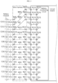
- FIG. 1 shows the battery module including battery cells and the battery monitoring circuit having voltage sensing channels connected through the wire harness and the circuit board.
- the number of battery cells is 12 and the number of voltage sensing channels is 14.
- the battery monitoring circuit includes fifteen voltage sensing pins P[1] ⁇ P[15], and the circuit board includes fifteen conducting patterns R[1] ⁇ R[15] and fifteen board terminals T[1] ⁇ T[15] having a one-to-one correspondence with the voltage sensing pins P[1] ⁇ P[15] of the battery monitoring circuit.
- One voltage sensing channel works every two adjacent voltage sensing pins (for example, P[2] and P[3]) among the voltage sensing pins P[1] ⁇ P[15], so the battery monitoring circuit includes a total of fourteen voltage sensing channels which is more than the number of battery cells C[1] ⁇ C[12] included in the battery module.
- the wire harness includes thirteen wires W[1] ⁇ W[13] that are larger than the number of battery cells by one.
- the wires W[1] ⁇ W[13] are connected, at one end, to each of connection terminals A[1] ⁇ A[13] and at the other end, to the board terminals B[1] ⁇ B[13].
- the twelve battery cells C[1] ⁇ C[12] may be connected in a one-to-one relationship to the twelve voltage sensing channels in a sequential order from the bottommost (lowest potential) voltage sensing channel among the fourteen voltage sensing channels of the battery monitoring circuit through the wire harness and the circuit board, and the remaining two voltage sensing channels formed by the top three voltage sensing pins P[13], P[14] and P[15] may stay in open state.
- a battery monitoring circuit having no particular constraint condition may normally measure the cell voltage of each battery cell even when two voltage sensing channels formed by the top three voltage sensing pins P[13], P[14] and P[15] are in open state like the connection structure shown in FIG. 1 .
- some battery monitoring circuits supplied by many manufacturers are employed due to their high performance but have a constraint condition for a predetermined number of voltage sensing channels in a sequential order from the top (highest potential). That is, to measure the cell voltage V[1] ⁇ V[12], it is necessary to apply a predetermined level or more of voltage to each of the predetermined number of voltage sensing channels from the top to normally operate the battery monitoring circuit.
- the battery monitoring circuit having the constraint condition cannot normally operate, and as a result, it is impossible to measure the cell voltage of any of the twelve battery cells C[1] ⁇ C[12].
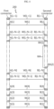
- FIG. 2 shows a modified connection mechanism of the wire harness to connect a predetermined number of top battery cells to a predetermined number of top voltage sensing channels of the battery monitoring circuit to solve the above-described problem caused by the constraint condition of the battery monitoring circuit.
- the wire harness of FIG. 2 further includes an additional wire WX and a relay board connection terminal BX, and in the same way as FIG.
- the bottom ten battery cells C[1] ⁇ C[10] are connected to the bottom eleven voltage sensing pins P[1] ⁇ P[11] in a sequential order through eleven wires W[1] ⁇ W[11], eleven board terminals T[1] ⁇ B[11] and eleven conducting patterns R[1] ⁇ R[11] and the top two battery cells C[11], C[12] are connected to the top three voltage sensing pins P[13] ⁇ P[15] in a sequential order through three wires WX, W[12], W[13], three board terminals T[13], B[14], B[15] and three conducting patterns R[13], R[14], R[15].
- the present disclosure is designed to solve the above-described problem, and therefore the present disclosure is directed to providing a circuit board that satisfies a constraint condition of a battery monitoring circuit without changing a hole size and a wire dimension of a wire harness and can be applied to a wide coverage of battery modules.
- a circuit board is for a battery monitoring circuit.
- the battery monitoring circuit includes first to (M+1)-th voltage sensing pins, and has an operating condition that a voltage is applied to (M-N+1) to (M+1)-th voltage sensing pins among the first to (M+1)-th voltage sensing pins.
- the circuit board includes first to (M+1)-th conducting patterns formed electrically separably from each other, and electrically connected, at an end, to the first to (M+1)-th voltage sensing pins in a one-to-one relationship, respectively; a relay conducting pattern, wherein an end of the relay conducting pattern is electrically connected to (M-N+1)-th conducting pattern electrically connected to the (M-N+1)-th voltage sensing pin among the first to (M+1)-th conducting patterns; first to (M+1)-th board terminals, each of the first to (M+1)-th board terminals being electrically connected to an opposite end of each of the first to (M+1)-th conducting patterns in a one-to-one relationship, respectively; and a relay board terminal electrically connected to an opposite end of the relay conducting pattern.
- M is a natural number of 3 or greater
- N is a natural number of less than M.
- the first to (M+1)-th board terminals may be spaced apart from each other in a sequential order corresponding to an order of location of the first to (M+1)-th voltage sensing pins.
- the circuit board may have a first surface in which the battery monitoring circuit is mounted and a second surface opposite the first surface, and the first to (M+1)-th conducting patterns and the relay conducting pattern may be formed on the first surface of the circuit board.
- the relay conducting pattern may be formed in a gap between a (M-N)-th conducting pattern and the (M-N+1)-th conducting pattern among the first to (M+1)-th conducting patterns on the first surface of the circuit board.
- the relay board terminal may be disposed in a gap between the (M-N)-th board terminal and the (M-N+1)-th board terminal among the first to (M+1)-th board terminals.
- the relay board terminal may be disposed to form an opposing relationship with the (M-N+1)-th board terminal in a thicknesswise direction of the circuit board.
- a wire harness is for connecting the circuit board to a battery module.
- the battery module includes first to L-th battery cells connected in series.
- the wire harness includes a first connector including first to (L+1)-th cell connection terminals; a second connector including first to (L+1)-th board connection terminals, a first relay board connection terminal and a second relay board connection terminal; first to (L+1)-th wires; and a relay wire.
- a k-th wire among the first to (L+1)-th wires electrically connects a k-th cell connection terminal among the first to (L+1)-th cell connection terminals to a k-th board connection terminal among the first to (L+1)-th board connection terminals.
- the first relay board connection terminal and the second relay board connection terminal are electrically connected by the relay wire.
- L is a natural number greater than N and smaller than M
- k is a natural number of (L+1) or smaller.
- the first relay board connection terminal may be electrically connected to the relay board terminal of the circuit board.
- the second relay board connection terminal may be electrically connected to the (L-N+1)-th board terminal among the first to (M+1)-th board terminals of the circuit board.
- the first to (L-N)-th board connection terminals among the first to (L+1)-th board connection terminals may be electrically connected in a one-to-one relationship to the first to (L-N)-th board terminals among the first to (M+1)-th board terminals.
- the (L-N+1) to (L+1)-th board connection terminals among the first to (L+1)-th board connection terminals may be electrically connected in a one-to-one relationship to the (M-N+1) to (M+1)-th board terminals among the first to (M+1)-th board terminals.
- the k-th cell connection terminal among the first to (L+1)-th cell connection terminals may be electrically connected to a negative terminal of the k-th battery cell among the first to L-th battery cells.
- the (L+1)-th cell connection terminal may be electrically connected to a positive terminal of the L-th battery cell.
- the circuit board that satisfies the constraint condition of the battery monitoring circuit without changing the hole size and the wire dimension of the wire harness and can be applied to a wide coverage of battery modules.
- the wire harness for transmitting the cell voltage of the plurality of battery cells of the battery module to the circuit board according to the pattern structure of the circuit board applicable to a wide coverage of battery modules.
- FIG. 3 is a diagram exemplarily showing a circuit board 100 according to an embodiment of the present disclosure.
- the circuit board 100 is equipped with a battery monitoring circuit 10 having a constraint condition for top N voltage sensing channels.
- N is a natural number of less than M.
- the battery monitoring circuit 10 may be referred to as 'BMIC', and basically includes a voltage measurement circuit (not shown) to measure the cell voltage, and may further include at least one functional circuit.
- the functional circuit may include, for example, a temperature measurement circuit, a cell balancing circuit or the like.
- the battery monitoring circuit 10 includes first to (M+1)-th voltage sensing pins P[1] ⁇ P[M+1].
- M is a natural number of 3 or greater.
- the first to (M+1)-th voltage sensing pins P[1] ⁇ P[M+1] a pair of two adjacent voltage sensing pins form one voltage sensing channel.
- i is a natural number of M or smaller
- the i-th voltage sensing pin P[i] and the (i+1)-th voltage sensing pin form the i-th voltage sensing channel.
- the i-th voltage sensing pin P[i] has lower potential than the (i+1)-th voltage sensing pin P[i+1], and a voltage difference between the i-th voltage sensing pin P[i] and the (i+1)-th voltage sensing pin P[i+1] is measured as the cell voltage.
- the first to (M+1)-th voltage sensing pins P[1] ⁇ P[M+1] form a total of M voltage sensing channels, and may correspond to a battery module including a maximum of M battery cells through the M voltage sensing channels.
- the battery monitoring circuit 10 has the constraint condition for top N voltage sensing channels as described above. That is, the operating condition (condition for cell voltage measurement) of the battery monitoring circuit 10 is an event of applying voltage to the (M-N+1) to (M+1)-th voltage sensing pins P[M-N+1] ⁇ P[M+1] among the first to (M+1)-th voltage sensing pins P[1] ⁇ P[M+1]. Accordingly, it is necessary to apply a predetermined level or more of voltage to each of the (M-N+1) to M-th voltage channels in order to measure the voltage in each of M voltage sensing channels.
- the (M-N+1)-th voltage sensing pin P[M-N+1] corresponds to the lowest potential among (N+1) voltage sensing pins P[M-N+1] ⁇ P[M+1]) having the constraint condition.
- the circuit board 100 has a first surface and a second surface opposite the first surface in the thicknesswise direction, and the battery monitoring circuit 10 is mounted on a circuit mounting area on the first surface of the circuit board 100.
- the circuit board 100 includes first to (M+1)-th conducting patterns R[1] ⁇ R[M+1] formed electrically separably from each other.
- the first to (M+1)-th conducting patterns R[1] ⁇ R[M+1] is, at one end, electrically connected to the first to (M+1)-th voltage sensing pins P[1] ⁇ P[M+1]) of the battery monitoring circuit 10 in a one-to-one relationship, respectively.
- the i-th conducting pattern R[i] may directly contact the i-th voltage sensing pin P[i] or may be indirectly connected to the i-th voltage sensing pin P[i] through Surface Mounter Technology (SMT).
- SMT Surface Mounter Technology
- the circuit board 100 further includes a relay conducting pattern RA.
- One end of the relay conducting pattern RA is electrically connected to the (M-N+1)-th conducting pattern R[M-N+1].
- the circuit board 100 further includes a terminal array.
- the terminal array includes first to (M+1)-th board terminals T[1] ⁇ T[M+1] and a relay board terminal TA.
- the first to (M+1)-th conducting patterns R[1] ⁇ R[M+1]) are, at the other end, electrically connected to the first to (M+1)-th board terminals T[1] ⁇ T[M+1] in a one-to-one relationship, respectively.
- the first to (M+1)-th board terminals T[1] ⁇ T[M+1] may be spaced apart from each other in a sequential order corresponding to the order of location of the first to (M+1)-th voltage sensing pins P[1] ⁇ P[M+1].
- the other end of the relay conducting pattern RA is electrically connected to the relay board terminal TA.
- the relay board terminal TA may be disposed in the gap between the (M-N)-th board terminal T[M-N] and the (M-N+1)-th board terminal T[M-N+1] among the first to (M+1)-th board terminals T[1] ⁇ T[M+1].
- the first to (M+1)-th conducting patterns R[1] ⁇ R[M+1] and the relay conducting pattern RA may be formed in any one of the first surface and the second surface opposite the first surface in the thicknesswise direction of the circuit board 100. At least one of the first to (M+1)-th conducting patterns R[1] ⁇ R[M+1] and the relay conducting pattern RA may be formed on the first surface and the remaining conducting patterns may be formed on the second surface.
- FIG. 4 is a diagram exemplarily showing a wire harness 200 according to an embodiment of the present disclosure.
- the wire harness 200 is configured to connect the circuit board 100 described with reference to FIG. 3 to the battery module BM (see FIG. 5 ).
- the wire harness 200 includes a first connector, a second connector and a connection portion.
- the first connector is used for mechanical and electrical coupling between the wire harness 200 and the battery module BM, and includes first to (L+1)-th cell connection terminals A[1] ⁇ A[L+1].
- L is a natural number of greater than N and smaller than M, and may be equal to the number of battery cells included in the battery module BM coupled to the first connector.
- the second connector is used for mechanical and electrical coupling between the wire harness 200 and the circuit board 100, and includes first to (L+1)-th board connection terminals B[1] ⁇ B[L+1], a first relay board connection terminal BA[1] and a second relay board connection terminal BA[2].
- the first relay board connection terminal BA[1] and the second relay board connection terminal BA[2] may be disposed in the separation area between the (L-N+1)-th board connection terminal B[L-N+1] and the (L-N)-th board connection terminal B[L-N].
- connection portion is used for mechanical and electrical coupling between the first connector and the second connector, and includes first to (L+1)-th wires W[1] ⁇ W[L+1] and a relay wire WA.
- a k-th wire W[k] among first to (L+1)-th wires W[1] ⁇ W[L+1] electrically connects a k-th cell connection terminal A[k] among the first to (L+1)-th cell connection terminals A[1] ⁇ A[L+1] to a k-th board connection terminal B[k] among the first to (L+1)-th board connection terminals B[1] ⁇ B[L+1].
- the relay wire WA electrically connects the first relay board connection terminal BA[1] to the second relay board connection terminal BA[2].
- the first relay board connection terminal BA[1] and the second relay board connection terminal BA[2] have substantially the equal potential by the relay wire WA.
- FIG. 5 is a diagram exemplarily showing the battery module BM including the plurality of battery cells connected in series is connected to the circuit board 100 shown in FIG. 3 through the wire harness 200 shown in FIG. 4 .
- M is larger than L by 3 or more
- L is larger than N by 4 or more.
- the battery module BM includes first to L-th battery cells C[1] ⁇ C[L] connected in series.
- the negative terminal of the first battery cell C[1] has the lowest potential and the positive terminal of the L-th battery cell C[L] has the highest potential.
- the negative terminal of the upper battery cell for example, C[2]
- the positive terminal of the other battery cell for example, C[1]
- the positive and negative terminals of the first to L-th battery cells C[1] ⁇ C[L] are electrically connected to the first to (L+1)-th cell connection terminals A[1] ⁇ A[L+1] of the wire harness 200.
- the k-th cell connection terminal A[k] may be electrically connected to the negative terminal of the k-th battery cell C[k] among the first to L-th battery cells C[1] ⁇ C[L].
- the (L+1)-th cell connection terminal may be electrically connected to the positive terminal of the L-th battery cell C[L].
- the first relay board connection terminal BA[1] is electrically connected to the relay board terminal TA of the circuit board 100
- the second relay board connection terminal BA[2] is electrically connected to the (L-N+1)-th board terminal T[L-N+1] among the first to (M+1)-th board terminals T[1] ⁇ T[M+1] of the circuit board 100.
- the first to (L-N)-th board connection terminals B[1]-B[L-N] among the first to (L+1)-th board connection terminals B[1] ⁇ B[L+1] are electrically connected to the first to (L-N)-th board terminals T[1]-T[L-N] among the first to (M+1)-th board terminals T[1] ⁇ T[M+1] in a one-to-one relationship.
- the cell voltage V[1] ⁇ V[L-N-1] of each of the first to (L-N-1)-th battery cells C[1] ⁇ C[L-N-1] is transmitted to the first to (L-N-1)-th voltage sensing channels of the battery monitoring circuit 10.
- the first relay board connection terminal BA[1] of the wire harness 200 is electrically connected to the relay board terminal TA of the circuit board 100
- the second relay board connection terminal BA[2] of the wire harness 200 is electrically connected to the (L-N+1)-th board terminal T[L-N+1] of the circuit board 100.
- the positive terminal of the (L-N)-th battery cell C[L-N] is electrically connected to the (L-N+1)-th voltage sensing pin P[L-N+1] of the battery monitoring circuit 10 through the (L-N+1)-th cell connection terminal A[L-N+1], the (L-N+1)-th wire W[L-N+1], the (L-N+1)-th board connection terminal B[L-N+1], the (M-N+1)-th board terminal T[M-N+1], the (M-N+1)-th conducting pattern R[M-N+1], the relay conducting pattern RA, the relay board terminal TA, the first relay board connection terminal BA[1], the relay wire WA, the second relay board connection terminal BA[2], the (L-N+1)-th board terminal T[L-N+1] and the (L-N+1)-th conducting pattern R[L-N+1].
- the negative terminal of the (L-N)-th battery cell C[L-N] is electrically connected to the (L-N)-th voltage sensing pin P[L-N] of the battery monitoring circuit 10 through the (L-N)-th cell connection terminal A[L-N], the (L-N)-th wire W[L-N], the (L-N)-th board connection terminal B[L-N], the (L-N)-th board terminal T[L-N] and the (L-N)-th conducting pattern R[L-N].
- the cell voltage V[L-N] of the (L-N)-th battery cell C[L-N] among the first to L-th battery cells C[1] ⁇ C[L] is transmitted to the (L-N)-th voltage sensing channel of the battery monitoring circuit 10 through two board terminals T[L-N+1] and T[L-N].
- the second connector of the wire harness 200 is coupled to the circuit board 100, among the first to (L+1)-th board connection terminals B[1] ⁇ B[L+1], the (L-N+1) to (L+1)-th board connection terminals B[L-N+1] ⁇ B[L+1] are electrically connected to the (M-N+1) to (M+1)-th board terminals T[M-N+1] ⁇ T[M+1] among the first to (M+1)-th board terminals T[1] ⁇ T[M+1] in a one-to-one relationship.
- the cell voltage V[L-N+1]-V[L] of each of the (L-N+1) to L-th battery cells C[L-N+1] ⁇ C[L]) is transmitted to the (M-N+1) to M-th voltage sensing channels of the battery monitoring circuit, and the constraint condition of the battery monitoring circuit 10 may be completely satisfied.
- the cell voltage of each of the first to (L-N-1)-th battery cells C[1] ⁇ C[L-N-1], the (L-N)-th battery cell C[L-N]) and the (L-N+1) to L-th battery cells C[L-N+1] ⁇ C[L] may be normally measured.
- the (L-N+2) to (M-N)-th board terminals T[L-N+2]-T[M-N] of the circuit board 100 are in open circuited state, and voltage is not applied to the (L-N+2) to (M-N)-th voltage sensing pins P[L-N+2]-P[M-N], and accordingly the (M-L-2) voltage sensing channels and the (L-N+2) to (M-N)-th voltage sensing channels stay in open state.
Landscapes
- Chemical & Material Sciences (AREA)
- Chemical Kinetics & Catalysis (AREA)
- Electrochemistry (AREA)
- General Chemical & Material Sciences (AREA)
- Engineering & Computer Science (AREA)
- Physics & Mathematics (AREA)
- General Physics & Mathematics (AREA)
- Manufacturing & Machinery (AREA)
- Microelectronics & Electronic Packaging (AREA)
- Secondary Cells (AREA)
- Battery Mounting, Suspending (AREA)
- Connection Of Batteries Or Terminals (AREA)
Abstract
Description
- The present disclosure relates to a circuit board for a battery monitoring circuit and a wire harness for connection therewith, and more particularly, to a circuit board for mounting a battery monitoring circuit provided to monitor the state of a set of battery cells connected in series, and a wire harness connecting the set of battery cells connected in series to the circuit board.
- The present application claims priority to
Korean Patent Application No. 10-2022-0116492 filed on September 15, 2022 - Recently, there has been a rapid increase in the demand for portable electronic products such as laptop computers, video cameras and mobile phones, and with the extensive development of electric vehicles, accumulators for energy storage, robots and satellites, many studies are being made on high performance batteries that can be repeatedly recharged.
- Currently, commercially available batteries include nickel-cadmium batteries, nickel-hydrogen batteries, nickel-zinc batteries, lithium secondary batteries and the like, and among them, lithium batteries have little or no memory effect, and thus they are gaining more attention than nickel-based batteries for their advantages that recharging can be done whenever it is convenient, the self-discharge rate is very low and the energy density is high.
- The minimum unit of a battery may be referred to as a battery cell, and a battery module includes a set of battery cells connected in series. A cell voltage or a voltage across each battery cell corresponds to a state parameter to be essentially measured to ensure safety and efficiency of not only the battery cell but also the battery module and a high level equipment such as an electric vehicle including the battery module.
- A battery monitoring circuit, one component of a battery management system, is connected to each of a positive terminal and a negative terminal of each battery cell included in the battery module through a wire harness, and plays a role in measuring the cell voltage for each battery cell, and transmitting voltage data indicating the measured cell voltage to a micro control unit (MCU).
- The number of battery cells included in the battery module is not fixed, and ranges from a few battery cells to a few tens of battery cells according to the purpose of use of the battery module.
- Since it is not efficient to manufacture each circuit board according to the specification of the battery module, it is necessary to employ a circuit board and a battery monitoring circuit having a sufficiently large number of voltage sensing paths for as wide coverage of battery modules as possible.
-
FIG. 1 shows the battery module including battery cells and the battery monitoring circuit having voltage sensing channels connected through the wire harness and the circuit board. For convenience of description, the number of battery cells is 12 and the number of voltage sensing channels is 14. - Referring to
FIG. 1 , the battery monitoring circuit includes fifteen voltage sensing pins P[1]~P[15], and the circuit board includes fifteen conducting patterns R[1]~R[15] and fifteen board terminals T[1]~T[15] having a one-to-one correspondence with the voltage sensing pins P[1]~P[15] of the battery monitoring circuit. One voltage sensing channel works every two adjacent voltage sensing pins (for example, P[2] and P[3]) among the voltage sensing pins P[1]~P[15], so the battery monitoring circuit includes a total of fourteen voltage sensing channels which is more than the number of battery cells C[1]~C[12] included in the battery module. - The wire harness includes thirteen wires W[1]~W[13] that are larger than the number of battery cells by one. The wires W[1]~W[13] are connected, at one end, to each of connection terminals A[1]~A[13] and at the other end, to the board terminals B[1]~B[13].
- The twelve battery cells C[1]~C[12] may be connected in a one-to-one relationship to the twelve voltage sensing channels in a sequential order from the bottommost (lowest potential) voltage sensing channel among the fourteen voltage sensing channels of the battery monitoring circuit through the wire harness and the circuit board, and the remaining two voltage sensing channels formed by the top three voltage sensing pins P[13], P[14] and P[15] may stay in open state.
- A battery monitoring circuit having no particular constraint condition may normally measure the cell voltage of each battery cell even when two voltage sensing channels formed by the top three voltage sensing pins P[13], P[14] and P[15] are in open state like the connection structure shown in
FIG. 1 . - However, some battery monitoring circuits supplied by many manufacturers are employed due to their high performance but have a constraint condition for a predetermined number of voltage sensing channels in a sequential order from the top (highest potential). That is, to measure the cell voltage V[1]~V[12], it is necessary to apply a predetermined level or more of voltage to each of the predetermined number of voltage sensing channels from the top to normally operate the battery monitoring circuit. When the top two voltage sensing channels stay in open state as shown in
FIG. 1 , the battery monitoring circuit having the constraint condition cannot normally operate, and as a result, it is impossible to measure the cell voltage of any of the twelve battery cells C[1]~C[12]. -
FIG. 2 shows a modified connection mechanism of the wire harness to connect a predetermined number of top battery cells to a predetermined number of top voltage sensing channels of the battery monitoring circuit to solve the above-described problem caused by the constraint condition of the battery monitoring circuit. Specifically, when compared with the wire harness ofFIG. 1 , the wire harness ofFIG. 2 further includes an additional wire WX and a relay board connection terminal BX, and in the same way asFIG. 1 , the bottom ten battery cells C[1]~C[10] are connected to the bottom eleven voltage sensing pins P[1]~P[11] in a sequential order through eleven wires W[1]~W[11], eleven board terminals T[1]~B[11] and eleven conducting patterns R[1]~R[11] and the top two battery cells C[11], C[12] are connected to the top three voltage sensing pins P[13]~P[15] in a sequential order through three wires WX, W[12], W[13], three board terminals T[13], B[14], B[15] and three conducting patterns R[13], R[14], R[15]. As opposed toFIG. 1 , two intermediate voltage sensing channels formed by the three voltage sensing pins P[11]~P[13] are in open state, but the constraint condition for the top two voltage sensing channels formed by the three voltage sensing pins P[13]~P[15] is satisfied, so the cell voltage measurement operation for the twelve battery cells C[1]~C[12] may be normally performed. - To establish the connection relationship shown in
FIG. 2 , it requires a structure in which the ends of two wires W[11] and WX in the wire harness are connected to an electrode terminal of a specific battery cell by inserting the ends of the two wires into a single hole of the connection terminal A[11], and simultaneously the two wires are branched within the wire harness so that the two wires can be connected to two different terminals T[11], T[13] of the circuit board respectively. However, to manufacture the wire harness of the corresponding structure, it requires a process of changing a hole size of the connection terminal A[11] and a wire dimension, and inserting the two wires W[11], WX into the single hole, causing high complexity, an unnecessary cost rise and an increase in manufacturing time. - The present disclosure is designed to solve the above-described problem, and therefore the present disclosure is directed to providing a circuit board that satisfies a constraint condition of a battery monitoring circuit without changing a hole size and a wire dimension of a wire harness and can be applied to a wide coverage of battery modules.
- These and other objectives and advantages of the present disclosure may be understood by the following description and will be apparent from embodiments of the present disclosure. In addition, it will be readily understood that the objectives and advantages of the present disclosure may be realized by the means set forth in the appended claims and a combination thereof.
- A circuit board according to an aspect of the present disclosure is for a battery monitoring circuit. The battery monitoring circuit includes first to (M+1)-th voltage sensing pins, and has an operating condition that a voltage is applied to (M-N+1) to (M+1)-th voltage sensing pins among the first to (M+1)-th voltage sensing pins. The circuit board includes first to (M+1)-th conducting patterns formed electrically separably from each other, and electrically connected, at an end, to the first to (M+1)-th voltage sensing pins in a one-to-one relationship, respectively; a relay conducting pattern, wherein an end of the relay conducting pattern is electrically connected to (M-N+1)-th conducting pattern electrically connected to the (M-N+1)-th voltage sensing pin among the first to (M+1)-th conducting patterns; first to (M+1)-th board terminals, each of the first to (M+1)-th board terminals being electrically connected to an opposite end of each of the first to (M+1)-th conducting patterns in a one-to-one relationship, respectively; and a relay board terminal electrically connected to an opposite end of the relay conducting pattern. M is a natural number of 3 or greater, and N is a natural number of less than M.
- The first to (M+1)-th board terminals may be spaced apart from each other in a sequential order corresponding to an order of location of the first to (M+1)-th voltage sensing pins.
- The circuit board may have a first surface in which the battery monitoring circuit is mounted and a second surface opposite the first surface, and the first to (M+1)-th conducting patterns and the relay conducting pattern may be formed on the first surface of the circuit board.
- The relay conducting pattern may be formed in a gap between a (M-N)-th conducting pattern and the (M-N+1)-th conducting pattern among the first to (M+1)-th conducting patterns on the first surface of the circuit board.
- The relay board terminal may be disposed in a gap between the (M-N)-th board terminal and the (M-N+1)-th board terminal among the first to (M+1)-th board terminals.
- The relay board terminal may be disposed to form an opposing relationship with the (M-N+1)-th board terminal in a thicknesswise direction of the circuit board.
- A wire harness according to another aspect of the present disclosure is for connecting the circuit board to a battery module. The battery module includes first to L-th battery cells connected in series. The wire harness includes a first connector including first to (L+1)-th cell connection terminals; a second connector including first to (L+1)-th board connection terminals, a first relay board connection terminal and a second relay board connection terminal; first to (L+1)-th wires; and a relay wire. A k-th wire among the first to (L+1)-th wires electrically connects a k-th cell connection terminal among the first to (L+1)-th cell connection terminals to a k-th board connection terminal among the first to (L+1)-th board connection terminals. The first relay board connection terminal and the second relay board connection terminal are electrically connected by the relay wire. L is a natural number greater than N and smaller than M, and k is a natural number of (L+1) or smaller.
- The first relay board connection terminal may be electrically connected to the relay board terminal of the circuit board. The second relay board connection terminal may be electrically connected to the (L-N+1)-th board terminal among the first to (M+1)-th board terminals of the circuit board.
- The first to (L-N)-th board connection terminals among the first to (L+1)-th board connection terminals may be electrically connected in a one-to-one relationship to the first to (L-N)-th board terminals among the first to (M+1)-th board terminals.
- The (L-N+1) to (L+1)-th board connection terminals among the first to (L+1)-th board connection terminals may be electrically connected in a one-to-one relationship to the (M-N+1) to (M+1)-th board terminals among the first to (M+1)-th board terminals.
- The k-th cell connection terminal among the first to (L+1)-th cell connection terminals may be electrically connected to a negative terminal of the k-th battery cell among the first to L-th battery cells.
- The (L+1)-th cell connection terminal may be electrically connected to a positive terminal of the L-th battery cell.
- According to at least one of the embodiments of the present disclosure, it may be possible to provide the circuit board that satisfies the constraint condition of the battery monitoring circuit without changing the hole size and the wire dimension of the wire harness and can be applied to a wide coverage of battery modules.
- Additionally, according to at least one of the embodiments of the present disclosure, it may be possible to provide the wire harness for transmitting the cell voltage of the plurality of battery cells of the battery module to the circuit board according to the pattern structure of the circuit board applicable to a wide coverage of battery modules.
- The effects of the present disclosure are not limited to the above-mentioned effects, and these and other effects will be clearly understood by those skilled in the art from the appended claims.
- The accompanying drawings illustrate exemplary embodiments of the present disclosure and together with the following detailed description, serve to provide a further understanding of the technical aspect of the present disclosure, and thus the present disclosure should not be construed as being limited to the drawings.
-
FIG. 1 is a diagram exemplarily showing that a battery monitoring circuit having no constraint condition associated with a predetermined number of top voltage sensing channels is connected to a battery module through a wire harness and a circuit board. -
FIG. 2 is a diagram exemplarily showing a circuit board having a battery monitoring circuit having a constraint condition associated with a predetermined number of top voltage sensing channels is mounted is connected to a battery module through a wire harness having a changed connection mechanism. -
FIG. 3 is a diagram exemplarily showing a circuit board according to an embodiment of the present disclosure. -
FIG. 4 is a diagram exemplarily showing a wire harness according to an embodiment of the present disclosure. -
FIG. 5 is a diagram exemplarily showing that a battery module (BM) including a plurality of battery cells connected in series is connected to the circuit board shown inFIG. 3 through the wire harness shown inFIG. 4 . - The detailed description of the objectives and technical features of the present disclosure and the technical effects will be understood more clearly by the following detailed description in accordance with the accompanying drawings. The embodiments according to the present disclosure will be described in detail with reference to the accompanying drawings.
- The embodiments disclosed herein should not be interpreted or used to limit the scope of the present disclosure. It is obvious to those skilled in the art that the description including the embodiments of the present disclosure has many different variations. Accordingly, arbitrary embodiments described in the detailed description of the present disclosure are provided for illustration purposes to describe the present disclosure better but not intended to limit the scope of the present disclosure to the disclosed embodiments.
- The terms including the ordinal number such as "first", "second" and the like, are used to distinguish one element from another among various elements, but not intended to limit the elements.
- Additionally, the term "comprises" is "open-ended" language and specifies the presence of stated elements, but does not preclude the presence or addition of one or more other elements.
- Further, it should be understood that when an element is referred to as being "connected to" another element, it can be directly connected to the other element or intervening elements may be present.
-
FIG. 3 is a diagram exemplarily showing acircuit board 100 according to an embodiment of the present disclosure. InFIG. 3 , thecircuit board 100 is equipped with abattery monitoring circuit 10 having a constraint condition for top N voltage sensing channels. Here, N is a natural number of less than M. - Referring to
FIG. 3 , thebattery monitoring circuit 10 may be referred to as 'BMIC', and basically includes a voltage measurement circuit (not shown) to measure the cell voltage, and may further include at least one functional circuit. The functional circuit may include, for example, a temperature measurement circuit, a cell balancing circuit or the like. - The
battery monitoring circuit 10 includes first to (M+1)-th voltage sensing pins P[1]~P[M+1]. Here, M is a natural number of 3 or greater. - Among the first to (M+1)-th voltage sensing pins P[1]~P[M+1], a pair of two adjacent voltage sensing pins form one voltage sensing channel. When i is a natural number of M or smaller, the i-th voltage sensing pin P[i] and the (i+1)-th voltage sensing pin form the i-th voltage sensing channel. For reference, the i-th voltage sensing pin P[i] has lower potential than the (i+1)-th voltage sensing pin P[i+1], and a voltage difference between the i-th voltage sensing pin P[i] and the (i+1)-th voltage sensing pin P[i+1] is measured as the cell voltage. Accordingly, the first to (M+1)-th voltage sensing pins P[1]~P[M+1] form a total of M voltage sensing channels, and may correspond to a battery module including a maximum of M battery cells through the M voltage sensing channels.
- The
battery monitoring circuit 10 has the constraint condition for top N voltage sensing channels as described above. That is, the operating condition (condition for cell voltage measurement) of thebattery monitoring circuit 10 is an event of applying voltage to the (M-N+1) to (M+1)-th voltage sensing pins P[M-N+1]~P[M+1] among the first to (M+1)-th voltage sensing pins P[1]~P[M+1]. Accordingly, it is necessary to apply a predetermined level or more of voltage to each of the (M-N+1) to M-th voltage channels in order to measure the voltage in each of M voltage sensing channels. The (M-N+1)-th voltage sensing pin P[M-N+1] corresponds to the lowest potential among (N+1) voltage sensing pins P[M-N+1]~P[M+1]) having the constraint condition. - The
circuit board 100 has a first surface and a second surface opposite the first surface in the thicknesswise direction, and thebattery monitoring circuit 10 is mounted on a circuit mounting area on the first surface of thecircuit board 100. - The
circuit board 100 includes first to (M+1)-th conducting patterns R[1]~R[M+1] formed electrically separably from each other. - The first to (M+1)-th conducting patterns R[1]~R[M+1] is, at one end, electrically connected to the first to (M+1)-th voltage sensing pins P[1]~P[M+1]) of the
battery monitoring circuit 10 in a one-to-one relationship, respectively. In this instance, the i-th conducting pattern R[i] may directly contact the i-th voltage sensing pin P[i] or may be indirectly connected to the i-th voltage sensing pin P[i] through Surface Mounter Technology (SMT). - In addition to the first to (M+1)-th conducting patterns R[1]~R[M+1], the
circuit board 100 further includes a relay conducting pattern RA. One end of the relay conducting pattern RA is electrically connected to the (M-N+1)-th conducting pattern R[M-N+1]. - The
circuit board 100 further includes a terminal array. The terminal array includes first to (M+1)-th board terminals T[1]~T[M+1] and a relay board terminal TA. - The first to (M+1)-th conducting patterns R[1]~R[M+1]) are, at the other end, electrically connected to the first to (M+1)-th board terminals T[1]~T[M+1] in a one-to-one relationship, respectively. In this instance, the first to (M+1)-th board terminals T[1]~T[M+1] may be spaced apart from each other in a sequential order corresponding to the order of location of the first to (M+1)-th voltage sensing pins P[1]~P[M+1].
- The other end of the relay conducting pattern RA is electrically connected to the relay board terminal TA. The relay board terminal TA may be disposed in the gap between the (M-N)-th board terminal T[M-N] and the (M-N+1)-th board terminal T[M-N+1] among the first to (M+1)-th board terminals T[1]~T[M+1].
- According to
FIG. 3 , the first to (M+1)-th conducting patterns R[1]~R[M+1] and the relay conducting pattern RA may be formed in any one of the first surface and the second surface opposite the first surface in the thicknesswise direction of thecircuit board 100. At least one of the first to (M+1)-th conducting patterns R[1]~R[M+1] and the relay conducting pattern RA may be formed on the first surface and the remaining conducting patterns may be formed on the second surface. -
FIG. 4 is a diagram exemplarily showing awire harness 200 according to an embodiment of the present disclosure. - Referring to
FIG. 4 , thewire harness 200 is configured to connect thecircuit board 100 described with reference toFIG. 3 to the battery module BM (seeFIG. 5 ). - The
wire harness 200 includes a first connector, a second connector and a connection portion. - The first connector is used for mechanical and electrical coupling between the
wire harness 200 and the battery module BM, and includes first to (L+1)-th cell connection terminals A[1]~A[L+1]. For reference, L is a natural number of greater than N and smaller than M, and may be equal to the number of battery cells included in the battery module BM coupled to the first connector. - The second connector is used for mechanical and electrical coupling between the
wire harness 200 and thecircuit board 100, and includes first to (L+1)-th board connection terminals B[1]~B[L+1], a first relay board connection terminal BA[1] and a second relay board connection terminal BA[2]. The first relay board connection terminal BA[1] and the second relay board connection terminal BA[2] may be disposed in the separation area between the (L-N+1)-th board connection terminal B[L-N+1] and the (L-N)-th board connection terminal B[L-N]. - The connection portion is used for mechanical and electrical coupling between the first connector and the second connector, and includes first to (L+1)-th wires W[1]~W[L+1] and a relay wire WA.
- When k is a natural number of (L+1) or smaller a k-th wire W[k] among first to (L+1)-th wires W[1]~W[L+1] electrically connects a k-th cell connection terminal A[k] among the first to (L+1)-th cell connection terminals A[1]~A[L+1] to a k-th board connection terminal B[k] among the first to (L+1)-th board connection terminals B[1]~B[L+1].
- The relay wire WA electrically connects the first relay board connection terminal BA[1] to the second relay board connection terminal BA[2]. The first relay board connection terminal BA[1] and the second relay board connection terminal BA[2] have substantially the equal potential by the relay wire WA.
-
FIG. 5 is a diagram exemplarily showing the battery module BM including the plurality of battery cells connected in series is connected to thecircuit board 100 shown inFIG. 3 through thewire harness 200 shown inFIG. 4 . For convenience of description, inFIG. 5 , M is larger than L by 3 or more, and L is larger than N by 4 or more. - Referring to
FIG. 5 , the battery module BM includes first to L-th battery cells C[1]~C[L] connected in series. - Among the first to L-th battery cells C[1]~C[L], the negative terminal of the first battery cell C[1] has the lowest potential and the positive terminal of the L-th battery cell C[L] has the highest potential. In this instance, among two adjacent battery cells (for example, C[1] and C[2]), the negative terminal of the upper battery cell (for example, C[2]) is electrically connected to the positive terminal of the other battery cell (for example, C[1]).
- When the first connector of the
wire harness 200 is coupled to the battery module BM, the positive and negative terminals of the first to L-th battery cells C[1]~C[L] are electrically connected to the first to (L+1)-th cell connection terminals A[1]~A[L+1] of thewire harness 200. - Specifically, among the first to (L+1)-th cell connection terminals A[1]~A[L+1], the k-th cell connection terminal A[k] may be electrically connected to the negative terminal of the k-th battery cell C[k] among the first to L-th battery cells C[1]~C[L]. The (L+1)-th cell connection terminal may be electrically connected to the positive terminal of the L-th battery cell C[L].
- When the second connector of the
wire harness 200 is coupled to thecircuit board 100, the first relay board connection terminal BA[1] is electrically connected to the relay board terminal TA of thecircuit board 100, and the second relay board connection terminal BA[2] is electrically connected to the (L-N+1)-th board terminal T[L-N+1] among the first to (M+1)-th board terminals T[1]~T[M+1] of thecircuit board 100. - When the second connector of the
wire harness 200 is coupled to thecircuit board 100, the first to (L-N)-th board connection terminals B[1]-B[L-N] among the first to (L+1)-th board connection terminals B[1]~B[L+1] are electrically connected to the first to (L-N)-th board terminals T[1]-T[L-N] among the first to (M+1)-th board terminals T[1]~T[M+1] in a one-to-one relationship. - Accordingly, among the first to L-th battery cells C[1]~C[L], the cell voltage V[1]~V[L-N-1] of each of the first to (L-N-1)-th battery cells C[1]~C[L-N-1] is transmitted to the first to (L-N-1)-th voltage sensing channels of the
battery monitoring circuit 10. - Additionally, when the second connector of the
wire harness 200 is coupled to thecircuit board 100, the first relay board connection terminal BA[1] of thewire harness 200 is electrically connected to the relay board terminal TA of thecircuit board 100, and the second relay board connection terminal BA[2] of thewire harness 200 is electrically connected to the (L-N+1)-th board terminal T[L-N+1] of thecircuit board 100. - The positive terminal of the (L-N)-th battery cell C[L-N] is electrically connected to the (L-N+1)-th voltage sensing pin P[L-N+1] of the
battery monitoring circuit 10 through the (L-N+1)-th cell connection terminal A[L-N+1], the (L-N+1)-th wire W[L-N+1], the (L-N+1)-th board connection terminal B[L-N+1], the (M-N+1)-th board terminal T[M-N+1], the (M-N+1)-th conducting pattern R[M-N+1], the relay conducting pattern RA, the relay board terminal TA, the first relay board connection terminal BA[1], the relay wire WA, the second relay board connection terminal BA[2], the (L-N+1)-th board terminal T[L-N+1] and the (L-N+1)-th conducting pattern R[L-N+1]. - Additionally, the negative terminal of the (L-N)-th battery cell C[L-N] is electrically connected to the (L-N)-th voltage sensing pin P[L-N] of the
battery monitoring circuit 10 through the (L-N)-th cell connection terminal A[L-N], the (L-N)-th wire W[L-N], the (L-N)-th board connection terminal B[L-N], the (L-N)-th board terminal T[L-N] and the (L-N)-th conducting pattern R[L-N]. - Accordingly, the cell voltage V[L-N] of the (L-N)-th battery cell C[L-N] among the first to L-th battery cells C[1]~C[L] is transmitted to the (L-N)-th voltage sensing channel of the
battery monitoring circuit 10 through two board terminals T[L-N+1] and T[L-N]. - Additionally, when the second connector of the
wire harness 200 is coupled to thecircuit board 100, among the first to (L+1)-th board connection terminals B[1]~B[L+1], the (L-N+1) to (L+1)-th board connection terminals B[L-N+1]~B[L+1] are electrically connected to the (M-N+1) to (M+1)-th board terminals T[M-N+1]~T[M+1] among the first to (M+1)-th board terminals T[1]~T[M+1] in a one-to-one relationship. - Accordingly, among the first to L-th battery cells C[1]~C[L], the cell voltage V[L-N+1]-V[L] of each of the (L-N+1) to L-th battery cells C[L-N+1]~C[L]) is transmitted to the (M-N+1) to M-th voltage sensing channels of the battery monitoring circuit, and the constraint condition of the
battery monitoring circuit 10 may be completely satisfied. - Through the above-described connection relationship, when the first connector and the second connector of the
wire harness 200 are coupled to the battery module BM and thecircuit board 100, respectively, the cell voltage of each of the first to (L-N-1)-th battery cells C[1]~C[L-N-1], the (L-N)-th battery cell C[L-N]) and the (L-N+1) to L-th battery cells C[L-N+1]~C[L] may be normally measured. - Meanwhile, when the second connector of the
wire harness 200 is coupled to thecircuit board 100, the (L-N+2) to (M-N)-th board terminals T[L-N+2]-T[M-N] of thecircuit board 100 are in open circuited state, and voltage is not applied to the (L-N+2) to (M-N)-th voltage sensing pins P[L-N+2]-P[M-N], and accordingly the (M-L-2) voltage sensing channels and the (L-N+2) to (M-N)-th voltage sensing channels stay in open state. - The present disclosure is not limited to the above-described particular embodiments and variations, and it is obvious that modifications and variations may be made thereto by those having ordinary skill in the technical field pertaining to the present disclosure without departing from the claimed subject matter of the present disclosure, and such modifications and variations should not be understood as being separate from the technical aspect or scope of the present disclosure.
Claims (10)
- A circuit board for a battery monitoring circuit including first to (M+1)-th voltage sensing pins and having an operating condition that a voltage is applied to (M-N+1) to (M+1)-th voltage sensing pins among the first to (M+1)-th voltage sensing pins, the circuit board comprising:first to (M+1)-th conducting patterns formed electrically separably from each other, and electrically connected, at an end, to the first to (M+1)-th voltage sensing pins in a one-to-one relationship, respectively;a relay conducting pattern, wherein an end of the relay conducting pattern is electrically connected to (M-N+1)-th conducting pattern electrically connected to the (M-N+1)-th voltage sensing pin among the first to (M+1)-th conducting patterns;first to (M+1)-th board terminals, each of the first to (M+1)-th board terminals being electrically connected to an opposite end of each of the first to (M+1)-th conducting patterns in a one-to-one relationship, respectively; anda relay board terminal electrically connected to an opposite end of the relay conducting pattern,wherein M is a natural number of 3 or greater, andwherein N is a natural number of less than M.
- The circuit board according to claim 1, wherein the first to (M+1)-th board terminals are spaced apart from each other in a sequential order corresponding to an order of location of the first to (M+1)-th voltage sensing pins.
- The circuit board according to claim 1, wherein the circuit board has a first surface in which the battery monitoring circuit is mounted and a second surface opposite the first surface, and the first to (M+1)-th conducting patterns and the relay conducting pattern are formed on the first surface of the circuit board.
- The circuit board according to claim 3, wherein the relay conducting pattern is formed in a gap between a (M-N)-th conducting pattern and the (M-N+1)-th conducting pattern among the first to (M+1)-th conducting patterns on the first surface of the circuit board.
- The circuit board according to claim 4, wherein the relay board terminal is disposed in a gap between the (M-N)-th board terminal and the (M-N+1)-th board terminal among the first to (M+1)-th board terminals.
- The circuit board according to claim 4, wherein the relay board terminal is disposed to form an opposing relationship with the (M-N+1)-th board terminal in a thicknesswise direction of the circuit board.
- A wire harness for connecting the circuit board according to claim 1 to a battery module including first to L-th battery cells connected in series, the wire harness comprising:a first connector including first to (L+1)-th cell connection terminals;a second connector including first to (L+1)-th board connection terminals, a first relay board connection terminal and a second relay board connection terminal;first to (L+1)-th wires; anda relay wire,wherein a k-th wire among the first to (L+1)-th wires electrically connects a k-th cell connection terminal among the first to (L+1)-th cell connection terminals to a k-th board connection terminal among the first to (L+1)-th board connection terminals,wherein the first relay board connection terminal and the second relay board connection terminal are electrically connected by the relay wire,wherein L is a natural number greater than N and smaller than M, andwherein k is a natural number of (L+1) or smaller.
- The wire harness according to claim 7, wherein the first relay board connection terminal is electrically connected to the relay board terminal of the circuit board, and
wherein the second relay board connection terminal is electrically connected to the (L-N+1)-th board terminal among the first to (M+1)-th board terminals of the circuit board. - The wire harness according to claim 7, wherein the first to (L-N)-th board connection terminals among the first to (L+1)-th board connection terminals are electrically connected in a one-to-one relationship to the first to (L-N)-th board terminals among the first to (M+1)-th board terminals, and
wherein the (L-N+1) to (L+1)-th board connection terminals among the first to (L+1)-th board connection terminals are electrically connected in a one-to-one relationship to the (M-N+1) to (M+1)-th board terminals among the first to (M+1)-th board terminals. - The wire harness according to claim 7, wherein the k-th cell connection terminal among the first to (L+1)-th cell connection terminals is electrically connected to a negative terminal of the k-th battery cell among the first to L-th battery cells, and
wherein the (L+1)-th cell connection terminal is electrically connected to a positive terminal of the L-th battery cell.
Applications Claiming Priority (2)
| Application Number | Priority Date | Filing Date | Title |
|---|---|---|---|
| KR1020220116492A KR102960545B1 (en) | 2022-09-15 | Circuit board for battery monitoring circuit and wire-harness for connection therewith | |
| PCT/KR2023/010129 WO2024058391A1 (en) | 2022-09-15 | 2023-07-14 | Circuit board for battery monitoring circuit and wire harness for connection therewith |
Publications (3)
| Publication Number | Publication Date |
|---|---|
| EP4407745A1 true EP4407745A1 (en) | 2024-07-31 |
| EP4407745A4 EP4407745A4 (en) | 2025-03-19 |
| EP4407745B1 EP4407745B1 (en) | 2026-03-11 |
Family
ID=90275495
Family Applications (1)
| Application Number | Title | Priority Date | Filing Date |
|---|---|---|---|
| EP23865694.6A Active EP4407745B1 (en) | 2022-09-15 | 2023-07-14 | Circuit board for battery monitoring circuit and wire harness for connection therewith |
Country Status (5)
| Country | Link |
|---|---|
| US (1) | US12578388B2 (en) |
| EP (1) | EP4407745B1 (en) |
| JP (1) | JP7703786B2 (en) |
| CN (1) | CN118176612A (en) |
| WO (1) | WO2024058391A1 (en) |
Family Cites Families (18)
| Publication number | Priority date | Publication date | Assignee | Title |
|---|---|---|---|---|
| JP2563707Y2 (en) * | 1990-08-07 | 1998-02-25 | 矢崎総業株式会社 | connector |
| US6304062B1 (en) * | 1999-10-28 | 2001-10-16 | Powersmart, Inc. | Shunt resistance device for monitoring battery state of charge |
| JP5287682B2 (en) | 2009-11-26 | 2013-09-11 | 株式会社デンソー | Battery monitoring device |
| JP5712841B2 (en) | 2011-07-25 | 2015-05-07 | 株式会社デンソー | Voltage detector |
| US8922165B2 (en) * | 2012-05-14 | 2014-12-30 | Freescale Semiconductor, Inc. | Cell balance configuration for pin count reduction |
| CN103618353A (en) | 2013-11-28 | 2014-03-05 | 深圳市劲力思特科技有限公司 | Battery monitoring circuit |
| US10056653B2 (en) * | 2013-12-10 | 2018-08-21 | Sanyo Electric Co., Ltd. | Battery management device and power supply device |
| CN204028329U (en) * | 2014-07-07 | 2014-12-17 | 安徽科技学院 | A kind of novel storage battery monitoring terminal circuit structure |
| KR102553944B1 (en) | 2016-07-13 | 2023-07-07 | 주식회사 엘지에너지솔루션 | Connecting board and battery pack including the same |
| JP6789768B2 (en) | 2016-11-15 | 2020-11-25 | 株式会社ケーヒン | Circuit protection device and power supply monitoring device |
| JP7213187B2 (en) * | 2017-08-29 | 2023-01-26 | ヌヴォトンテクノロジージャパン株式会社 | Voltage detection circuit |
| JP6950661B2 (en) | 2018-10-29 | 2021-10-13 | 株式会社デンソー | Battery monitoring device |
| KR102405847B1 (en) | 2019-01-10 | 2022-06-03 | 주식회사 엘지에너지솔루션 | Apparatus for managing battery and battery pack including the same |
| KR102787047B1 (en) | 2019-05-10 | 2025-03-25 | 삼성에스디아이 주식회사 | Battery monitoring module |
| JP2023505717A (en) | 2019-12-13 | 2023-02-10 | エヴァテック・アーゲー | Gas ring of PVD source |
| KR102877552B1 (en) | 2020-10-06 | 2025-10-27 | 주식회사 엘지에너지솔루션 | Battery apparatus and method for measuring cell voltage |
| KR102888277B1 (en) * | 2021-01-21 | 2025-11-18 | 주식회사 엘지에너지솔루션 | Busbar diagnosis apparatus, battery pack, energy storage system, and busbar diagnosis method |
| EP4287352A4 (en) | 2021-01-29 | 2025-05-07 | Panasonic Energy Co., Ltd. | POWER SOURCE DEVICE AND METHOD FOR MANUFACTURING SAME |
-
2023
- 2023-07-14 JP JP2024524481A patent/JP7703786B2/en active Active
- 2023-07-14 WO PCT/KR2023/010129 patent/WO2024058391A1/en not_active Ceased
- 2023-07-14 CN CN202380014194.8A patent/CN118176612A/en active Pending
- 2023-07-14 EP EP23865694.6A patent/EP4407745B1/en active Active
- 2023-07-14 US US18/699,666 patent/US12578388B2/en active Active
Also Published As
| Publication number | Publication date |
|---|---|
| JP7703786B2 (en) | 2025-07-07 |
| US12578388B2 (en) | 2026-03-17 |
| US20240402252A1 (en) | 2024-12-05 |
| CN118176612A (en) | 2024-06-11 |
| JP2024541003A (en) | 2024-11-06 |
| WO2024058391A1 (en) | 2024-03-21 |
| EP4407745B1 (en) | 2026-03-11 |
| EP4407745A4 (en) | 2025-03-19 |
| KR20240037678A (en) | 2024-03-22 |
Similar Documents
| Publication | Publication Date | Title |
|---|---|---|
| US20250015443A1 (en) | Battery module with flexible interconnector | |
| US8603663B2 (en) | Battery pack | |
| EP3316384B1 (en) | Battery module with a fixing for a temperature sensitive element | |
| US9360529B2 (en) | Battery module and method of testing the same | |
| KR20200071614A (en) | FPCB assembly for battery module and a method for manufacturing FPCB assembly and a battery module including the same | |
| KR102671847B1 (en) | Battery module with flexible interconnector | |
| KR102449819B1 (en) | Battery apparatus having galvanic isolation communication architecture | |
| KR101802926B1 (en) | Battery having Sensing Assembly Structure for Processing Signal of Cell | |
| CN113131099A (en) | Battery pack | |
| KR101613497B1 (en) | Uninterruptible power supply module unit and uninterruptible power supply having the same | |
| EP4407745A1 (en) | Circuit board for battery monitoring circuit and wire harness for connection therewith | |
| US20250266629A1 (en) | Method for electrically connecting electronic components of a battery system and battery system | |
| KR102960545B1 (en) | Circuit board for battery monitoring circuit and wire-harness for connection therewith | |
| CN213210272U (en) | Double-deck FPC's of electricity core module sampling structure and battery module | |
| CN117276992B (en) | Switching box | |
| US20250096341A1 (en) | Apparatus for measuring battery temperature | |
| EP4436201B1 (en) | Battery pack | |
| CN218939946U (en) | Soft packet of battery module keysets | |
| US20240097284A1 (en) | Battery system with flexible printed circuit | |
| US20240106083A1 (en) | Battery system with flexible printed circuit | |
| US11075411B2 (en) | Protection circuit module, battery pack, and method of manufacturing the battery pack | |
| KR20250132900A (en) | BMS communication system and ESS communication system that communicate wirelessly |
Legal Events
| Date | Code | Title | Description |
|---|---|---|---|
| STAA | Information on the status of an ep patent application or granted ep patent |
Free format text: STATUS: THE INTERNATIONAL PUBLICATION HAS BEEN MADE |
|
| PUAI | Public reference made under article 153(3) epc to a published international application that has entered the european phase |
Free format text: ORIGINAL CODE: 0009012 |
|
| STAA | Information on the status of an ep patent application or granted ep patent |
Free format text: STATUS: REQUEST FOR EXAMINATION WAS MADE |
|
| 17P | Request for examination filed |
Effective date: 20240423 |
|
| AK | Designated contracting states |
Kind code of ref document: A1 Designated state(s): AL AT BE BG CH CY CZ DE DK EE ES FI FR GB GR HR HU IE IS IT LI LT LU LV MC ME MK MT NL NO PL PT RO RS SE SI SK SM TR |
|
| A4 | Supplementary search report drawn up and despatched |
Effective date: 20250217 |
|
| RIC1 | Information provided on ipc code assigned before grant |
Ipc: G01R 31/3835 20190101ALI20250211BHEP Ipc: H01M 50/569 20210101ALI20250211BHEP Ipc: G01R 31/396 20190101ALI20250211BHEP Ipc: G01R 31/36 20200101ALI20250211BHEP Ipc: H05K 1/14 20060101ALI20250211BHEP Ipc: G01R 31/364 20190101ALI20250211BHEP Ipc: H01M 50/298 20210101ALI20250211BHEP Ipc: H01M 50/519 20210101ALI20250211BHEP Ipc: H01M 10/48 20060101ALI20250211BHEP Ipc: H01M 10/42 20060101AFI20250211BHEP |
|
| GRAP | Despatch of communication of intention to grant a patent |
Free format text: ORIGINAL CODE: EPIDOSNIGR1 |
|
| STAA | Information on the status of an ep patent application or granted ep patent |
Free format text: STATUS: GRANT OF PATENT IS INTENDED |
|
| DAV | Request for validation of the european patent (deleted) | ||
| DAX | Request for extension of the european patent (deleted) | ||
| INTG | Intention to grant announced |
Effective date: 20251202 |
|
| GRAS | Grant fee paid |
Free format text: ORIGINAL CODE: EPIDOSNIGR3 |
|
| GRAA | (expected) grant |
Free format text: ORIGINAL CODE: 0009210 |
|
| STAA | Information on the status of an ep patent application or granted ep patent |
Free format text: STATUS: THE PATENT HAS BEEN GRANTED |
|
| P01 | Opt-out of the competence of the unified patent court (upc) registered |
Free format text: CASE NUMBER: UPC_APP_0000295_4407745/2026 Effective date: 20260106 |
|
| AK | Designated contracting states |
Kind code of ref document: B1 Designated state(s): AL AT BE BG CH CY CZ DE DK EE ES FI FR GB GR HR HU IE IS IT LI LT LU LV MC ME MK MT NL NO PL PT RO RS SE SI SK SM TR |
|
| REG | Reference to a national code |
Ref country code: CH Ref legal event code: F10 Free format text: ST27 STATUS EVENT CODE: U-0-0-F10-F00 (AS PROVIDED BY THE NATIONAL OFFICE) Effective date: 20260311 Ref country code: GB Ref legal event code: FG4D |
|
| REG | Reference to a national code |
Ref country code: DE Ref legal event code: R096 Ref document number: 602023013538 Country of ref document: DE |
|
| REG | Reference to a national code |
Ref country code: IE Ref legal event code: FG4D |