EP4407639A1 - High-temperature electrical device and method of making the same - Google Patents
High-temperature electrical device and method of making the same Download PDFInfo
- Publication number
- EP4407639A1 EP4407639A1 EP24150087.5A EP24150087A EP4407639A1 EP 4407639 A1 EP4407639 A1 EP 4407639A1 EP 24150087 A EP24150087 A EP 24150087A EP 4407639 A1 EP4407639 A1 EP 4407639A1
- Authority
- EP
- European Patent Office
- Prior art keywords
- bobbin
- oxidation
- composition
- temperature
- corrosion resistant
- Prior art date
- Legal status (The legal status is an assumption and is not a legal conclusion. Google has not performed a legal analysis and makes no representation as to the accuracy of the status listed.)
- Granted
Links
Images




Classifications
-
- H—ELECTRICITY
- H01—ELECTRIC ELEMENTS
- H01F—MAGNETS; INDUCTANCES; TRANSFORMERS; SELECTION OF MATERIALS FOR THEIR MAGNETIC PROPERTIES
- H01F5/00—Coils
- H01F5/02—Coils wound on non-magnetic supports, e.g. formers
-
- H—ELECTRICITY
- H01—ELECTRIC ELEMENTS
- H01F—MAGNETS; INDUCTANCES; TRANSFORMERS; SELECTION OF MATERIALS FOR THEIR MAGNETIC PROPERTIES
- H01F41/00—Apparatus or processes specially adapted for manufacturing or assembling magnets, inductances or transformers; Apparatus or processes specially adapted for manufacturing materials characterised by their magnetic properties
- H01F41/02—Apparatus or processes specially adapted for manufacturing or assembling magnets, inductances or transformers; Apparatus or processes specially adapted for manufacturing materials characterised by their magnetic properties for manufacturing cores, coils, or magnets
- H01F41/04—Apparatus or processes specially adapted for manufacturing or assembling magnets, inductances or transformers; Apparatus or processes specially adapted for manufacturing materials characterised by their magnetic properties for manufacturing cores, coils, or magnets for manufacturing coils
- H01F41/06—Coil winding
- H01F41/098—Mandrels; Formers
-
- H—ELECTRICITY
- H01—ELECTRIC ELEMENTS
- H01F—MAGNETS; INDUCTANCES; TRANSFORMERS; SELECTION OF MATERIALS FOR THEIR MAGNETIC PROPERTIES
- H01F41/00—Apparatus or processes specially adapted for manufacturing or assembling magnets, inductances or transformers; Apparatus or processes specially adapted for manufacturing materials characterised by their magnetic properties
- H01F41/02—Apparatus or processes specially adapted for manufacturing or assembling magnets, inductances or transformers; Apparatus or processes specially adapted for manufacturing materials characterised by their magnetic properties for manufacturing cores, coils, or magnets
-
- H—ELECTRICITY
- H01—ELECTRIC ELEMENTS
- H01F—MAGNETS; INDUCTANCES; TRANSFORMERS; SELECTION OF MATERIALS FOR THEIR MAGNETIC PROPERTIES
- H01F27/00—Details of transformers or inductances, in general
- H01F27/23—Corrosion protection
-
- H—ELECTRICITY
- H01—ELECTRIC ELEMENTS
- H01F—MAGNETS; INDUCTANCES; TRANSFORMERS; SELECTION OF MATERIALS FOR THEIR MAGNETIC PROPERTIES
- H01F27/00—Details of transformers or inductances, in general
- H01F27/28—Coils; Windings; Conductive connections
- H01F27/32—Insulating of coils, windings, or parts thereof
- H01F27/324—Insulation between coil and core, between different winding sections, around the coil; Other insulation structures
-
- H—ELECTRICITY
- H01—ELECTRIC ELEMENTS
- H01F—MAGNETS; INDUCTANCES; TRANSFORMERS; SELECTION OF MATERIALS FOR THEIR MAGNETIC PROPERTIES
- H01F41/00—Apparatus or processes specially adapted for manufacturing or assembling magnets, inductances or transformers; Apparatus or processes specially adapted for manufacturing materials characterised by their magnetic properties
- H01F41/005—Impregnating or encapsulating
-
- H—ELECTRICITY
- H01—ELECTRIC ELEMENTS
- H01F—MAGNETS; INDUCTANCES; TRANSFORMERS; SELECTION OF MATERIALS FOR THEIR MAGNETIC PROPERTIES
- H01F41/00—Apparatus or processes specially adapted for manufacturing or assembling magnets, inductances or transformers; Apparatus or processes specially adapted for manufacturing materials characterised by their magnetic properties
- H01F41/02—Apparatus or processes specially adapted for manufacturing or assembling magnets, inductances or transformers; Apparatus or processes specially adapted for manufacturing materials characterised by their magnetic properties for manufacturing cores, coils, or magnets
- H01F41/04—Apparatus or processes specially adapted for manufacturing or assembling magnets, inductances or transformers; Apparatus or processes specially adapted for manufacturing materials characterised by their magnetic properties for manufacturing cores, coils, or magnets for manufacturing coils
- H01F41/06—Coil winding
- H01F41/064—Winding non-flat conductive wires, e.g. rods, cables or cords
-
- H—ELECTRICITY
- H01—ELECTRIC ELEMENTS
- H01F—MAGNETS; INDUCTANCES; TRANSFORMERS; SELECTION OF MATERIALS FOR THEIR MAGNETIC PROPERTIES
- H01F41/00—Apparatus or processes specially adapted for manufacturing or assembling magnets, inductances or transformers; Apparatus or processes specially adapted for manufacturing materials characterised by their magnetic properties
- H01F41/02—Apparatus or processes specially adapted for manufacturing or assembling magnets, inductances or transformers; Apparatus or processes specially adapted for manufacturing materials characterised by their magnetic properties for manufacturing cores, coils, or magnets
- H01F41/04—Apparatus or processes specially adapted for manufacturing or assembling magnets, inductances or transformers; Apparatus or processes specially adapted for manufacturing materials characterised by their magnetic properties for manufacturing cores, coils, or magnets for manufacturing coils
- H01F41/12—Insulating of windings
- H01F41/125—Other insulating structures; Insulating between coil and core, between different winding sections, around the coil
-
- H—ELECTRICITY
- H01—ELECTRIC ELEMENTS
- H01F—MAGNETS; INDUCTANCES; TRANSFORMERS; SELECTION OF MATERIALS FOR THEIR MAGNETIC PROPERTIES
- H01F7/00—Magnets
- H01F7/06—Electromagnets; Actuators including electromagnets
-
- H—ELECTRICITY
- H01—ELECTRIC ELEMENTS
- H01F—MAGNETS; INDUCTANCES; TRANSFORMERS; SELECTION OF MATERIALS FOR THEIR MAGNETIC PROPERTIES
- H01F7/00—Magnets
- H01F7/06—Electromagnets; Actuators including electromagnets
- H01F7/08—Electromagnets; Actuators including electromagnets with armatures
- H01F7/128—Encapsulating, encasing or sealing
-
- H—ELECTRICITY
- H01—ELECTRIC ELEMENTS
- H01F—MAGNETS; INDUCTANCES; TRANSFORMERS; SELECTION OF MATERIALS FOR THEIR MAGNETIC PROPERTIES
- H01F7/00—Magnets
- H01F7/06—Electromagnets; Actuators including electromagnets
- H01F7/08—Electromagnets; Actuators including electromagnets with armatures
- H01F7/081—Magnetic constructions
Definitions
- the present disclosure relates to electrical devices and, more particularly, relates to high-temperature electrical devices and methods of making the same.
- Solenoid devices are electromechanical devices that convert electrical energy into linear mechanical movement. Solenoid devices are used in myriad environments and for many applications, and typically include at least a coil, a bobbin, a housing, and a movable armature. When the coil is energized, a magnetic field is generated that exerts a force on the movable armature, moving it to a desired position.
- a method of fabricating a high-temperature bobbin for a solenoid assembly includes the step of providing a bobbin configured for use in the solenoid assembly.
- the bobbin is coated with an anti-oxidation composition and an anti-corrosion composition to produce an oxidation/corrosion resistant bobbin.
- the oxidation/corrosion resistant bobbin is coated with an electrical insulating composition that is resistant to corona discharge at or below a predetermined voltage threshold to produce an insulated and oxidation/corrosion resistant bobbin.
- the anti-oxidation composition, the anti-corrosion composition, and the electrical insulating composition can withstand temperatures of subzero up to temperature greater than 1000°F.
- a method of fabricating a high-temperature bobbin for electrical device includes providing a bobbin configured for use in the electrical device.
- the bobbin is coated with an anti-oxidation composition and an anti-corrosion composition to produce an oxidation/corrosion resistant bobbin.
- the oxidation/corrosion resistant bobbin is coated with an electrical insulating composition that is resistant to corona discharge at or below a predetermined voltage threshold to produce an insulated and oxidation/corrosion resistant bobbin.
- the anti-oxidation composition, the anti-corrosion composition, and the electrical insulating composition can withstand temperatures of subzero up to temperature greater than 1000°F.
- the solenoid device 100 includes at least a housing assembly 102, a bobbin 104, a coil 106, and an armature 108.
- the housing assembly 102 includes a housing 112, a front cover plate 114, and a back cover plate 116.
- the housing 112 is configured to include a housing first end 118, a housing second end 122, and an inner surface 124 that defines a housing cavity 126.
- the housing 112 may comprise any one of numerous materials having a relatively high magnetic permeability such as, for example, magnetic steel.
- the housing 112 in addition to having a plurality of components disposed therein, provides a flux path, together with the bobbin assembly 104, for magnetic flux that the coil 106 generates when it is electrically energized.
- the front cover plate 114 is coupled to the housing first end 118 and the back cover plate 116 is coupled to the housing second end 122.
- the front and back covers 114, 116 may also preferably comprise any one of numerous materials having a relatively high magnetic permeability.
- the bobbin 104 is disposed within the housing cavity 126 and fixedly coupled to the housing 112.
- the bobbin 104 preferably comprises a material having a relatively high magnetic permeability and, as will be described in more detail below, is coated with an anti-oxidation and anti-corrosion composition, and an electrical insulating composition.
- the bobbin 104 together with the housing 112 and the armature 108, provides a magnetic flux path for the magnetic flux that is generated when the coil 106 is energized.
- the coil 106 is disposed within the housing 112 and is adapted to be electrically energized from a non-illustrated electrical power source. As noted above, when energized, the coil 106 generates magnetic flux. As depicted, the coil 106 is wound around a portion of the bobbin 104, and comprises a high-temperature insulated magnet wire. Although one coil 106 is depicted in FIG. 1 , it will be appreciated that the solenoid device 100 could be configured with more than this number of coils, if needed or desired. It will be appreciated that the high-temperature insulated magnet wire may be any one of numerous known types of high-temperature insulated magnet wire.
- Some non-limiting examples include, but are not limited to, the high-temperature insulated magnet wire disclosed in U.S. Patent No. 8,484,831 , the high-temperature insulated magnet wire disclosed in U.S. Patent No. 11,437,188 , the high-temperature insulated magnet wire disclosed in U.S. Patent No. 7,795,538 , or the high-temperature insulated magnet wire disclosed in U.S. Patent Application Serial No. 17/651,092 , all of which are assigned to the Assignee of the instant application.
- the armature 108 is disposed (at least partially) within the housing assembly 102. More specifically, the bobbin 104 has an inner surface 128 that defines an armature cavity 132. The armature 108 is disposed (at least partially) within the armature cavity 132 and is axially movable relative to the bobbin 104.
- the armature 108 preferably comprises a material having a relatively high magnetic permeability. As noted previously, the armature 108, together with the housing 112, and the bobbin 104, provides a magnetic flux path for the magnetic flux that is generated by the coil 106 when it is energized. This results in axial movement of the armature 108 within the housing 112 between a first position (depicted in FIG. 1 ) and a second position (not depicted).
- the solenoid device 100 depicted in FIG. 1 additionally includes a bias spring 134 and a plurality of feedthroughs 136 (136-1, 136-2).
- the bias spring 134 which may be variously implemented, is disposed within the armature cavity 132 and engages the housing 112 (more specifically, the back cover 116) and the armature 108.
- the bias spring 134 at least in the depicted embodiment, is configured to supply a bias force that urges the armature 108 toward the first position. It will be appreciated, however, that in other embodiments, the spring 134 could be disposed such that it supplies a bias force that urges the armature 108 toward the second position.
- the feedthroughs 136 are preferably formed of a ceramic material and are bonded to the bobbin 104. More specifically, each feedthrough 136 extends through, and are bonded in, a separate opening 138 formed in the bobbin 104. A portion of the high-temperature insulated magnet wire extends through each of the feedthroughs 136 for connection to a non-illustrated external power source. In some embodiments, a joint can be made between the high-temperature magnet wire and lead wires (not separately depicted) inside the housing 112 before being passed through the feedthroughs 136. Moreover, in some alternative embodiments, the feedthroughs 136 may be configured to allow the high-temperature magnet wire-to-lead wire joint to be made inside the feedthroughs 136.
- the depicted solenoid device 100 is able to withstand temperatures of subzero up to temperatures that exceed 1000°F. This, in part, is due to the process that is used to fabricate the bobbin 104 and then assemble the solenoid device 100. With reference now to FIGS. 2-5 , this process will now be described in more detail.
- the process 200 begins by obtaining a suitable bobbin (202).
- An oxidation/corrosion resistant bobbin 300 (see FIG. 3 ) is then produced by coating the bobbin 302 with an anti-oxidation and anti-corrosion composition 304 (204).
- the specific anti-oxidation and anti-corrosion composition 304 may vary, and may be implemented using a single composition or plural compositions, but in each case the selected composition(s) can withstand temperatures of subzero up to temperature greater than 1000°F and may also impart electrical insulation properties.
- suitable anti-oxidation and anti-corrosion compositions 304 include Bismuth Oxide, Boron Oxide, Zinc Oxide, ternary glass, silicate, or borate glasses, just to name a few.
- some additional processing steps such as drying and/or firing in a furnace, may be implemented to produce the oxidation/corrosion resistant bobbin 300.
- the specific number and type of additional processing steps may depend, for example, on the specific anti-oxidation and anti-corrosion composition 304 that is used.
- the additional processing steps drying the coated bobbin in an oven at a temperature around 120°C. In some embodiments, heating to an intermediate temperature of 80°C may be required. After drying, the bobbin is then heated to about 300°C to eliminate organics and the vehicle (depending on the composition), and then heating the bobbin to the desired processing condition of the coating (approximately 600-850°C). This latter step may require a specialized atmosphere (e.g., nitrogen, argon, etc).
- a specialized atmosphere e.g., nitrogen, argon, etc.
- an insulated and oxidation/corrosion resistant bobbin 400 is produced by coating the oxidation/corrosion resistant bobbin 300 with an electrical insulating composition 402 (206).
- the specific electrical insulating composition 402 may vary, but the selected composition is resistant to corona discharge at or below a predetermined breakdown voltage threshold (V B ).
- V B breakdown voltage threshold
- suitable electrical insulating compositions 402 include Bismuth Oxide, Boron Oxide, Zinc Oxide, ternary glass, silicate, or borate glasses, just to name a few.
- the value of 1500V is generally added since it is the minimum for lightning strike resistance.
- the electrical insulation thickness can vary depending on the breakdown voltage requirements of the device.
- the electrical insulating composition can also withstand temperatures of subzero up to temperature greater than 1000°F.
- additional processing steps may be implemented to produce the insulated and oxidation/corrosion resistant bobbin 400.
- the specific number and type of additional processing steps may depend, for example, on the specific electrical insulating composition 402 that is used.
- the additional processing steps heating the bobbin to approximately 600-850°C, depending on the specific composition. This step may require a specialized atmospheres (e.g., nitrogen, argon, etc).
- the feedthroughs 136 are disposed within a separate one of the openings 138 formed in the bobbin 104 and are bonded thereto (208).
- the feedthroughs 136 are preferably formed of a ceramic material such as, for example, alumina, Macor ® , Zirconia, quartz, glasses, and glass-metal, just to name a few.
- the feedthroughs 136 are preferably bonded via a metal bonding using the same materials as the anti-oxidation and anti-corrosion composition 304, the electrical insulating composition 402, various cements, and/or various geopolymers.
- the insulated and oxidation/corrosion resistant bobbin 400 preferably undergoes a voltage breakdown test (212).
- the voltage breakdown test ensures that the insulated and oxidation/corrosion resistant bobbin 400 can withstand the above-described breakdown voltage (V B ), which may or may not include the 1500V lightning strike margin, depending on the end-use environment. If the insulated and oxidation/corrosion resistant bobbin 400 does not pass the voltage breakdown test (213), additional electrical insulating composition 402 is applied (214) and the voltage breakdown test (212) is run again. These steps are repeated until the insulated and oxidation/corrosion resistant bobbin 400 passes the voltage breakdown test (213).
- the high-temperature insulated wire 106 is wound onto the insulated and oxidation/corrosion resistant bobbin 400 and a portion of the high-temperature insulated wire is passed through each of the ceramic feedthroughs 136 to thereby produce the high-temperature bobbin 104 (216).
- the high-temperature bobbin 104 is then disposed within housing 112 (218), and a potting material 602 (see FIG. 6 ), such as a high-temperature geopolymer potting material, is then injected into the housing 112 (222) such that the potting material 602 surrounds at least a portion of the high-temperature bobbin 104.
- the potting material 602 may then be processed, either before or after the armature 108 are bias spring 134 installed, and the front and back cover plates 114, 116 are coupled to the housing first and second ends 118, 122. It will be appreciated that if, as noted above, the magnet wire-to-lead wire joint is inside the housing 112, then the injected potting material 602 also surrounds the joint.
- suitable high-temperature geopolymer potting materials include, for example, various sodium-silicates, various alumino-silicates, and various magnesia-silicates.
- the assembly may then undergo additional/final thermal processing to allow the high-temperature geopolymer potting material to dry/cure. This processing may entail, for example, placing the assembly in an oven/furnace and raising the temperature directly to the desired temperature - typically just above the expected maximum operating temperature of the device. For example, if the desired operating temperature of the device is 750°F, the oven/furnace temperature may be set to 800°F, and allowed to soak overnight.
- compositions mentioned above were described as being applied to the bobbin 104, it will be appreciated that, at least in some embodiments, these compositions may also be applied to one or more of the armature 108, the housing 112, and/or the front and back cover plates 114, 116. It will additionally be appreciated that the processing steps described herein may also be used with other similar devices, such as a linear variable differential transformer (LVDT) sensor.
- LVDT linear variable differential transformer
- the term “axial” refers to a direction that is generally parallel to or coincident with an axis of rotation, axis of symmetry, or centerline of a component or components.
- the "axial" direction may refer to the direction that generally extends in parallel to the centerline between the opposite ends or faces.
- the term “axial” may be utilized with respect to components that are not cylindrical (or otherwise radially symmetric).
- the "axial" direction for a rectangular housing containing a rotating shaft may be viewed as a direction that is generally parallel to or coincident with the rotational axis of the shaft.
- radially may refer to a direction or a relationship of components with respect to a line extending outward from a shared centerline, axis, or similar reference, for example in a plane of a cylinder or disc that is perpendicular to the centerline or axis.
- components may be viewed as “radially” aligned even though one or both of the components may not be cylindrical (or otherwise radially symmetric).
- the terms “axial” and “radial” (and any derivatives) may encompass directional relationships that are other than precisely aligned with (e.g., oblique to) the true axial and radial dimensions, provided the relationship is predominantly in the respective nominal axial or radial direction.
- the term “substantially” denotes within 5% to account for manufacturing tolerances.
- the term “about” denotes within 5% to account for manufacturing tolerances.
Landscapes
- Engineering & Computer Science (AREA)
- Power Engineering (AREA)
- Manufacturing & Machinery (AREA)
- Physics & Mathematics (AREA)
- Electromagnetism (AREA)
- Electromagnets (AREA)
Abstract
Description
- The present disclosure relates to electrical devices and, more particularly, relates to high-temperature electrical devices and methods of making the same.
- Solenoid devices are electromechanical devices that convert electrical energy into linear mechanical movement. Solenoid devices are used in myriad environments and for many applications, and typically include at least a coil, a bobbin, a housing, and a movable armature. When the coil is energized, a magnetic field is generated that exerts a force on the movable armature, moving it to a desired position.
- Existing solenoid devices have limited operating temperatures, due to the use of organic insulation materials, and thus may exhibit premature failure due to material degradation (i.e., oxidation, corrosion, etc.) of various components that may occur at relatively high temperatures (e.g., approximately 550°F, depending on atmospheric conditions). These relatively high temperatures can be caused by the ambient conditions of the environment in which the solenoid device is installed, or the heat generated while the coil is being energized during a hold period, or a mixture of both. Such high temperatures can adversely impact lifetime, accuracy, and reliability. Thus, in some instances cooling systems may be used to cool the devices.
- Hence, there is a need to provide solenoid devices that can operate at relatively high temperatures (e.g. >750°F, specifically ≥ 1000°F) by, among other things, prohibiting oxidation and corrosion of the metallic components of solenoid device, prohibiting degradation of the coil materials, and improving the reliability of the magnetic components in the whole assembly level. The present disclosure addresses at least this need.
- This summary is provided to describe select concepts in a simplified form that are further described in the Detailed Description. This summary is not intended to identify key or essential features of the claimed subject matter, nor is it intended to be used as an aid in determining the scope of the claimed subject matter.
- In one embodiment, a method of fabricating a high-temperature bobbin for a solenoid assembly includes the step of providing a bobbin configured for use in the solenoid assembly. The bobbin is coated with an anti-oxidation composition and an anti-corrosion composition to produce an oxidation/corrosion resistant bobbin. The oxidation/corrosion resistant bobbin is coated with an electrical insulating composition that is resistant to corona discharge at or below a predetermined voltage threshold to produce an insulated and oxidation/corrosion resistant bobbin. The anti-oxidation composition, the anti-corrosion composition, and the electrical insulating composition can withstand temperatures of subzero up to temperature greater than 1000°F.
- In another embodiment, a method of fabricating a high-temperature bobbin for electrical device includes providing a bobbin configured for use in the electrical device. The bobbin is coated with an anti-oxidation composition and an anti-corrosion composition to produce an oxidation/corrosion resistant bobbin. The oxidation/corrosion resistant bobbin is coated with an electrical insulating composition that is resistant to corona discharge at or below a predetermined voltage threshold to produce an insulated and oxidation/corrosion resistant bobbin. The anti-oxidation composition, the anti-corrosion composition, and the electrical insulating composition can withstand temperatures of subzero up to temperature greater than 1000°F.
- Furthermore, other desirable features and characteristics of the bobbin and electrical device and method will become apparent from the subsequent detailed description and the appended claims, taken in conjunction with the accompanying drawings and the preceding background.
- The present disclosure will hereinafter be described in conjunction with the following drawing figures, wherein like numerals denote like elements, and wherein:
-
FIG. 1 depicts a simplified cross section view of one exemplary embodiment of a solenoid device; -
FIG. 2 depicts an embodiment of a process, in flowchart form, that is used to fabricate the bobbin used in the solenoid device ofFIG. 1 and to assemble the solenoid device; -
FIG. 3 depicts one embodiment of an oxidation/corrosion resistant bobbin; -
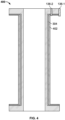
FIG. 4 depicts one embodiment of an insulated and oxidation/corrosion resistant bobbin; -
FIG. 5 depicts one embodiment of high-temperature bobbin; and -
FIG. 6 depicts the insulated and oxidation/corrosion resistant bobbin ofFIG. 4 installed within a housing and at least partially surrounded by a potting material. - The following detailed description is merely exemplary in nature and is not intended to limit the invention or the application and uses of the invention. As used herein, the word "exemplary" means "serving as an example, instance, or illustration." Thus, any embodiment described herein as "exemplary" is not necessarily to be construed as preferred or advantageous over other embodiments. All of the embodiments described herein are exemplary embodiments provided to enable persons skilled in the art to make or use the invention and not to limit the scope of the invention which is defined by the claims. Furthermore, there is no intention to be bound by any expressed or implied theory presented in the preceding technical field, background, brief summary, or the following detailed description.
- Referring to
FIG. 1 , a simplified cross section view of one exemplary embodiment of asolenoid device 100 is depicted. Thesolenoid device 100 includes at least ahousing assembly 102, abobbin 104, acoil 106, and anarmature 108. Thehousing assembly 102 includes ahousing 112, afront cover plate 114, and aback cover plate 116. Thehousing 112 is configured to include a housingfirst end 118, a housingsecond end 122, and aninner surface 124 that defines ahousing cavity 126. Thehousing 112 may comprise any one of numerous materials having a relatively high magnetic permeability such as, for example, magnetic steel. Thehousing 112, in addition to having a plurality of components disposed therein, provides a flux path, together with thebobbin assembly 104, for magnetic flux that thecoil 106 generates when it is electrically energized. Thefront cover plate 114 is coupled to the housingfirst end 118 and theback cover plate 116 is coupled to the housingsecond end 122. The front and back covers 114, 116 may also preferably comprise any one of numerous materials having a relatively high magnetic permeability. - The
bobbin 104 is disposed within thehousing cavity 126 and fixedly coupled to thehousing 112. Thebobbin 104 preferably comprises a material having a relatively high magnetic permeability and, as will be described in more detail below, is coated with an anti-oxidation and anti-corrosion composition, and an electrical insulating composition. Thebobbin 104, together with thehousing 112 and thearmature 108, provides a magnetic flux path for the magnetic flux that is generated when thecoil 106 is energized. - The
coil 106 is disposed within thehousing 112 and is adapted to be electrically energized from a non-illustrated electrical power source. As noted above, when energized, thecoil 106 generates magnetic flux. As depicted, thecoil 106 is wound around a portion of thebobbin 104, and comprises a high-temperature insulated magnet wire. Although onecoil 106 is depicted inFIG. 1 , it will be appreciated that thesolenoid device 100 could be configured with more than this number of coils, if needed or desired. It will be appreciated that the high-temperature insulated magnet wire may be any one of numerous known types of high-temperature insulated magnet wire. Some non-limiting examples include, but are not limited to, the high-temperature insulated magnet wire disclosed inU.S. Patent No. 8,484,831 , the high-temperature insulated magnet wire disclosed inU.S. Patent No. 11,437,188 U.S. Patent No. 7,795,538 , or the high-temperature insulated magnet wire disclosed inU.S. Patent Application Serial No. 17/651,092 , all of which are assigned to the Assignee of the instant application. - The
armature 108 is disposed (at least partially) within thehousing assembly 102. More specifically, thebobbin 104 has aninner surface 128 that defines anarmature cavity 132. Thearmature 108 is disposed (at least partially) within thearmature cavity 132 and is axially movable relative to thebobbin 104. Thearmature 108 preferably comprises a material having a relatively high magnetic permeability. As noted previously, thearmature 108, together with thehousing 112, and thebobbin 104, provides a magnetic flux path for the magnetic flux that is generated by thecoil 106 when it is energized. This results in axial movement of thearmature 108 within thehousing 112 between a first position (depicted inFIG. 1 ) and a second position (not depicted). - The
solenoid device 100 depicted inFIG. 1 additionally includes abias spring 134 and a plurality of feedthroughs 136 (136-1, 136-2). Thebias spring 134, which may be variously implemented, is disposed within thearmature cavity 132 and engages the housing 112 (more specifically, the back cover 116) and thearmature 108. Thebias spring 134, at least in the depicted embodiment, is configured to supply a bias force that urges thearmature 108 toward the first position. It will be appreciated, however, that in other embodiments, thespring 134 could be disposed such that it supplies a bias force that urges thearmature 108 toward the second position. - The feedthroughs 136 are preferably formed of a ceramic material and are bonded to the
bobbin 104. More specifically, each feedthrough 136 extends through, and are bonded in, a separate opening 138 formed in thebobbin 104. A portion of the high-temperature insulated magnet wire extends through each of the feedthroughs 136 for connection to a non-illustrated external power source. In some embodiments, a joint can be made between the high-temperature magnet wire and lead wires (not separately depicted) inside thehousing 112 before being passed through the feedthroughs 136. Moreover, in some alternative embodiments, the feedthroughs 136 may be configured to allow the high-temperature magnet wire-to-lead wire joint to be made inside the feedthroughs 136. - The depicted
solenoid device 100 is able to withstand temperatures of subzero up to temperatures that exceed 1000°F. This, in part, is due to the process that is used to fabricate thebobbin 104 and then assemble thesolenoid device 100. With reference now toFIGS. 2-5 , this process will now be described in more detail. - As depicted in flowchart form in
FIG. 2 , theprocess 200 begins by obtaining a suitable bobbin (202). An oxidation/corrosion resistant bobbin 300 (seeFIG. 3 ) is then produced by coating thebobbin 302 with an anti-oxidation and anti-corrosion composition 304 (204). The specific anti-oxidation andanti-corrosion composition 304 may vary, and may be implemented using a single composition or plural compositions, but in each case the selected composition(s) can withstand temperatures of subzero up to temperature greater than 1000°F and may also impart electrical insulation properties. Some non-limiting examples of suitable anti-oxidation andanti-corrosion compositions 304 include Bismuth Oxide, Boron Oxide, Zinc Oxide, ternary glass, silicate, or borate glasses, just to name a few. - As may be appreciated, at least in some embodiments, some additional processing steps, such as drying and/or firing in a furnace, may be implemented to produce the oxidation/corrosion
resistant bobbin 300. The specific number and type of additional processing steps may depend, for example, on the specific anti-oxidation andanti-corrosion composition 304 that is used. In one particular example, the additional processing steps drying the coated bobbin in an oven at a temperature around 120°C. In some embodiments, heating to an intermediate temperature of 80°C may be required. After drying, the bobbin is then heated to about 300°C to eliminate organics and the vehicle (depending on the composition), and then heating the bobbin to the desired processing condition of the coating (approximately 600-850°C). This latter step may require a specialized atmosphere (e.g., nitrogen, argon, etc). - No matter the particular additional processing steps, thereafter an insulated and oxidation/corrosion
resistant bobbin 400 is produced by coating the oxidation/corrosionresistant bobbin 300 with an electrical insulating composition 402 (206). The specific electricalinsulating composition 402 may vary, but the selected composition is resistant to corona discharge at or below a predetermined breakdown voltage threshold (VB). Some non-limiting examples of suitable electricalinsulating compositions 402 include Bismuth Oxide, Boron Oxide, Zinc Oxide, ternary glass, silicate, or borate glasses, just to name a few. Additionally, the predetermined voltage threshold may vary, but it is preferably based on the equation VB=2*Va+1500, where Va is the expected applied voltage in the system. It is noted that the value of 1500V is generally added since it is the minimum for lightning strike resistance. The electrical insulation thickness can vary depending on the breakdown voltage requirements of the device. Moreover, just like the anti-oxidation composition and the anti-corrosion composition, the electrical insulating composition can also withstand temperatures of subzero up to temperature greater than 1000°F. - As may be appreciated, at least in some embodiments, some additional processing steps, may be implemented to produce the insulated and oxidation/corrosion
resistant bobbin 400. The specific number and type of additional processing steps may depend, for example, on the specific electricalinsulating composition 402 that is used. In one particular example, the additional processing steps heating the bobbin to approximately 600-850°C, depending on the specific composition. This step may require a specialized atmospheres (e.g., nitrogen, argon, etc). - After the insulated and oxidation/corrosion
resistant bobbin 400 is produced, the feedthroughs 136 are disposed within a separate one of the openings 138 formed in thebobbin 104 and are bonded thereto (208). As noted above, the feedthroughs 136 are preferably formed of a ceramic material such as, for example, alumina, Macor®, Zirconia, quartz, glasses, and glass-metal, just to name a few. The feedthroughs 136 are preferably bonded via a metal bonding using the same materials as the anti-oxidation andanti-corrosion composition 304, the electricalinsulating composition 402, various cements, and/or various geopolymers. - As
FIG. 2 also depicts, after the feedthroughs 136 are bonded to thebobbin 104, the insulated and oxidation/corrosionresistant bobbin 400 preferably undergoes a voltage breakdown test (212). The voltage breakdown test ensures that the insulated and oxidation/corrosionresistant bobbin 400 can withstand the above-described breakdown voltage (VB), which may or may not include the 1500V lightning strike margin, depending on the end-use environment. If the insulated and oxidation/corrosionresistant bobbin 400 does not pass the voltage breakdown test (213), additional electricalinsulating composition 402 is applied (214) and the voltage breakdown test (212) is run again. These steps are repeated until the insulated and oxidation/corrosionresistant bobbin 400 passes the voltage breakdown test (213). - After passing the voltage breakdown test, and as depicted in
FIG. 5 , the high-temperature insulatedwire 106 is wound onto the insulated and oxidation/corrosionresistant bobbin 400 and a portion of the high-temperature insulated wire is passed through each of the ceramic feedthroughs 136 to thereby produce the high-temperature bobbin 104 (216). The high-temperature bobbin 104 is then disposed within housing 112 (218), and a potting material 602 (seeFIG. 6 ), such as a high-temperature geopolymer potting material, is then injected into the housing 112 (222) such that thepotting material 602 surrounds at least a portion of the high-temperature bobbin 104. Thepotting material 602 may then be processed, either before or after thearmature 108 arebias spring 134 installed, and the front andback cover plates housing 112, then the injectedpotting material 602 also surrounds the joint. - Some examples of suitable high-temperature geopolymer potting materials include, for example, various sodium-silicates, various alumino-silicates, and various magnesia-silicates. The assembly may then undergo additional/final thermal processing to allow the high-temperature geopolymer potting material to dry/cure. This processing may entail, for example, placing the assembly in an oven/furnace and raising the temperature directly to the desired temperature - typically just above the expected maximum operating temperature of the device. For example, if the desired operating temperature of the device is 750°F, the oven/furnace temperature may be set to 800°F, and allowed to soak overnight.
- It will be appreciated that although the various compositions mentioned above were described as being applied to the
bobbin 104, it will be appreciated that, at least in some embodiments, these compositions may also be applied to one or more of thearmature 108, thehousing 112, and/or the front andback cover plates - In this document, relational terms such as first and second, and the like may be used solely to distinguish one entity or action from another entity or action without necessarily requiring or implying any actual such relationship or order between such entities or actions. Numerical ordinals such as "first," "second," "third," etc. simply denote different singles of a plurality and do not imply any order or sequence unless specifically defined by the claim language. The sequence of the text in any of the claims does not imply that process steps must be performed in a temporal or logical order according to such sequence unless it is specifically defined by the language of the claim. The process steps may be interchanged in any order without departing from the scope of the invention as long as such an interchange does not contradict the claim language and is not logically nonsensical.
- Furthermore, depending on the context, words such as "connect" or "coupled to" used in describing a relationship between different elements do not imply that a direct physical connection must be made between these elements. For example, two elements may be connected to each other physically, electronically, logically, or in any other manner, through one or more additional elements.
- As used herein, the term "axial" refers to a direction that is generally parallel to or coincident with an axis of rotation, axis of symmetry, or centerline of a component or components. For example, in a cylinder or disc with a centerline and generally circular ends or opposing faces, the "axial" direction may refer to the direction that generally extends in parallel to the centerline between the opposite ends or faces. In certain instances, the term "axial" may be utilized with respect to components that are not cylindrical (or otherwise radially symmetric). For example, the "axial" direction for a rectangular housing containing a rotating shaft may be viewed as a direction that is generally parallel to or coincident with the rotational axis of the shaft. Furthermore, the term "radially" as used herein may refer to a direction or a relationship of components with respect to a line extending outward from a shared centerline, axis, or similar reference, for example in a plane of a cylinder or disc that is perpendicular to the centerline or axis. In certain instances, components may be viewed as "radially" aligned even though one or both of the components may not be cylindrical (or otherwise radially symmetric). Furthermore, the terms "axial" and "radial" (and any derivatives) may encompass directional relationships that are other than precisely aligned with (e.g., oblique to) the true axial and radial dimensions, provided the relationship is predominantly in the respective nominal axial or radial direction. As used herein, the term "substantially" denotes within 5% to account for manufacturing tolerances. Also, as used herein, the term "about" denotes within 5% to account for manufacturing tolerances.
- While at least one exemplary embodiment has been presented in the foregoing detailed description of the invention, it should be appreciated that a vast number of variations exist. It should also be appreciated that the exemplary embodiment or exemplary embodiments are only examples, and are not intended to limit the scope, applicability, or configuration of the invention in any way. Rather, the foregoing detailed description will provide those skilled in the art with a convenient road map for implementing an exemplary embodiment of the invention. It being understood that various changes may be made in the function and arrangement of elements described in an exemplary embodiment without departing from the scope of the invention as set forth in the appended claims.
Claims (5)
- A method of fabricating a high-temperature bobbin for an electrical device, comprising the steps of:providing a bobbin configured for use in an electrical device;coating the bobbin with an anti-oxidation composition and an anti-corrosion composition to produce an oxidation/corrosion resistant bobbin; andcoating the oxidation/corrosion resistant bobbin with an electrical insulating composition that is resistant to corona discharge at or below a predetermined voltage threshold to produce an insulated and oxidation/corrosion resistant bobbin,wherein the anti-oxidation composition, the anti-corrosion composition, and the electrical insulating composition can withstand temperatures of subzero up to temperature greater than 1000°F.
- The method of claim 1, further comprising:
bonding a plurality of ceramic feedthroughs to a portion of the insulated and oxidation/corrosion resistant bobbin. - The method of claim 2, further comprising:
winding high-temperature insulated wire onto the insulated and oxidation/corrosion resistant bobbin and extending a portion of the high-temperature insulated wire through the ceramic feedthroughs to thereby produce a high-temperature bobbin. - The method of claim 3, further comprising:disposing the high-temperature bobbin within a housing; andinserting a potting material into the housing such that the potting surrounds at least a portion of the high-temperature bobbin.
- The method of claim 1, further comprising:
coating the insulated and oxidation/corrosion resistant bobbin with additional electrical insulating composition.
Applications Claiming Priority (1)
| Application Number | Priority Date | Filing Date | Title |
|---|---|---|---|
| US18/159,245 US12614665B2 (en) | 2023-01-25 | 2023-01-25 | Method of fabricating a high-temperature bobbin for electrical device |
Publications (2)
| Publication Number | Publication Date |
|---|---|
| EP4407639A1 true EP4407639A1 (en) | 2024-07-31 |
| EP4407639B1 EP4407639B1 (en) | 2025-07-16 |
Family
ID=89430158
Family Applications (1)
| Application Number | Title | Priority Date | Filing Date |
|---|---|---|---|
| EP24150087.5A Active EP4407639B1 (en) | 2023-01-25 | 2024-01-02 | High-temperature electrical device and method of making the same |
Country Status (3)
| Country | Link |
|---|---|
| US (1) | US12614665B2 (en) |
| EP (1) | EP4407639B1 (en) |
| CN (1) | CN118398364A (en) |
Citations (6)
| Publication number | Priority date | Publication date | Assignee | Title |
|---|---|---|---|---|
| US7795538B2 (en) | 2007-11-06 | 2010-09-14 | Honeywell International Inc. | Flexible insulated wires for use in high temperatures and methods of manufacturing |
| US20130021125A1 (en) * | 2011-07-20 | 2013-01-24 | Honeywell International Inc. | Electromagnetic coil assemblies having tapered crimp joints and methods for the production thereof |
| US8484831B2 (en) | 2010-07-27 | 2013-07-16 | Honeywell International Inc. | Methods of forming insulated wires and hermetically-sealed packages for use in electromagnetic devices |
| US20180053595A1 (en) * | 2016-08-19 | 2018-02-22 | Meggitt Aerospace Limited (trading as Meggitt Control Systems) (Coventry) | Electromagnetic coils and methods of making same |
| US20190066913A1 (en) * | 2017-08-31 | 2019-02-28 | Sensata Technologies, Inc. | Electromagnetic coil |
| US11437188B2 (en) | 2018-09-25 | 2022-09-06 | Honeywell International Inc. | Low porosity glass coatings formed on coiled wires, high temperature devices containing the same, and methods for the fabrication thereof |
Family Cites Families (7)
| Publication number | Priority date | Publication date | Assignee | Title |
|---|---|---|---|---|
| US6596393B1 (en) * | 2000-04-20 | 2003-07-22 | Commscope Properties, Llc | Corrosion-protected coaxial cable, method of making same and corrosion-inhibiting composition |
| CN205542229U (en) | 2016-05-04 | 2016-08-31 | 千志电子科技(湖北)有限公司 | High temperature resistant, corrosion -resistant type wire winding type resistor |
| JP6743520B2 (en) | 2016-06-27 | 2020-08-19 | Tdk株式会社 | Coil device |
| US10431362B1 (en) * | 2018-05-15 | 2019-10-01 | Ademco Inc. | Valve actuator with anti-corrosion coating |
| CN208767058U (en) | 2018-11-08 | 2019-04-19 | 湖北首通电磁线科技有限公司 | A kind of novel enamel covered wire |
| CN110371793A (en) | 2019-08-15 | 2019-10-25 | 苏州恒可鸣纺织有限公司 | A kind of weaving weaving tube |
| CN111524693A (en) | 2020-05-09 | 2020-08-11 | 上海硕大电子科技有限公司 | Solenoid coil |
-
2023
- 2023-01-25 US US18/159,245 patent/US12614665B2/en active Active
- 2023-12-20 CN CN202311760101.4A patent/CN118398364A/en active Pending
-
2024
- 2024-01-02 EP EP24150087.5A patent/EP4407639B1/en active Active
Patent Citations (6)
| Publication number | Priority date | Publication date | Assignee | Title |
|---|---|---|---|---|
| US7795538B2 (en) | 2007-11-06 | 2010-09-14 | Honeywell International Inc. | Flexible insulated wires for use in high temperatures and methods of manufacturing |
| US8484831B2 (en) | 2010-07-27 | 2013-07-16 | Honeywell International Inc. | Methods of forming insulated wires and hermetically-sealed packages for use in electromagnetic devices |
| US20130021125A1 (en) * | 2011-07-20 | 2013-01-24 | Honeywell International Inc. | Electromagnetic coil assemblies having tapered crimp joints and methods for the production thereof |
| US20180053595A1 (en) * | 2016-08-19 | 2018-02-22 | Meggitt Aerospace Limited (trading as Meggitt Control Systems) (Coventry) | Electromagnetic coils and methods of making same |
| US20190066913A1 (en) * | 2017-08-31 | 2019-02-28 | Sensata Technologies, Inc. | Electromagnetic coil |
| US11437188B2 (en) | 2018-09-25 | 2022-09-06 | Honeywell International Inc. | Low porosity glass coatings formed on coiled wires, high temperature devices containing the same, and methods for the fabrication thereof |
Also Published As
| Publication number | Publication date |
|---|---|
| US12614665B2 (en) | 2026-04-28 |
| US20240249878A1 (en) | 2024-07-25 |
| CN118398364A (en) | 2024-07-26 |
| EP4407639B1 (en) | 2025-07-16 |
Similar Documents
| Publication | Publication Date | Title |
|---|---|---|
| EP2495740B1 (en) | High temperature electromagnetic coil assembly and method of the production thereof | |
| US8839505B2 (en) | Method of manufacturing a magnet assembly | |
| US6538543B2 (en) | Particle-impeding and ventilated solenoid actuator | |
| EP4407639B1 (en) | High-temperature electrical device and method of making the same | |
| EP0660490A1 (en) | A rotor provided with a ring-shaped magnet | |
| CA2853064C (en) | Magnetic chip detector/collector | |
| Cozonac et al. | Materials characterization and geometry of a high temperature induction machine | |
| Vannini et al. | Materials for electric machines suited for high-temperature applications: a survey | |
| US9035514B2 (en) | Jacketed electromagnetic machine stator for use in a corrosive atmosphere without heat treatment | |
| EP3629344B1 (en) | Low porosity glass coatings formed on coiled wires, high temperature devices containing the same, and methods for the fabrication thereof | |
| Mitsui | Progress in Japan in electrical insulation at high temperatures | |
| US2909713A (en) | High temperature solenoid | |
| US20100276832A1 (en) | Composite metal molding and method for manufacturing thereof | |
| US20160064132A1 (en) | High temperature solenoid actuator | |
| EP3875916A1 (en) | Linear variable differential transducer core structure | |
| US2802187A (en) | Magnetic reactor core and method of forming | |
| US20240425420A1 (en) | Electromechanical devices and methods for forming coating layers on components thereof | |
| WO2021182521A1 (en) | Electromagnetic relay | |
| KR20220034444A (en) | A manufacturing method of temperature sensor using measure of exhaust gas | |
| CN121356281B (en) | A lightweight permanent magnet propulsion motor resistant to high and low temperatures and low air pressure | |
| JP2022107513A (en) | Joint, electrical feedthrough, and sensor | |
| US20200028334A1 (en) | Spark plug with polymer sealing ring | |
| JP2022114769A (en) | Magnet loss measurement system and magnet loss measurement method | |
| JPS61198611A (en) | Manufacture of transformer with amorphous alloy thin band core | |
| JPH0822760A (en) | Magnetic switch for starter |
Legal Events
| Date | Code | Title | Description |
|---|---|---|---|
| PUAI | Public reference made under article 153(3) epc to a published international application that has entered the european phase |
Free format text: ORIGINAL CODE: 0009012 |
|
| STAA | Information on the status of an ep patent application or granted ep patent |
Free format text: STATUS: THE APPLICATION HAS BEEN PUBLISHED |
|
| AK | Designated contracting states |
Kind code of ref document: A1 Designated state(s): AL AT BE BG CH CY CZ DE DK EE ES FI FR GB GR HR HU IE IS IT LI LT LU LV MC ME MK MT NL NO PL PT RO RS SE SI SK SM TR |
|
| P01 | Opt-out of the competence of the unified patent court (upc) registered |
Free format text: CASE NUMBER: APP_61769/2024 Effective date: 20241119 |
|
| STAA | Information on the status of an ep patent application or granted ep patent |
Free format text: STATUS: REQUEST FOR EXAMINATION WAS MADE |
|
| GRAP | Despatch of communication of intention to grant a patent |
Free format text: ORIGINAL CODE: EPIDOSNIGR1 |
|
| STAA | Information on the status of an ep patent application or granted ep patent |
Free format text: STATUS: GRANT OF PATENT IS INTENDED |
|
| 17P | Request for examination filed |
Effective date: 20250113 |
|
| RIC1 | Information provided on ipc code assigned before grant |
Ipc: H01F 7/08 20060101ALN20250130BHEP Ipc: H01F 41/00 20060101ALI20250130BHEP Ipc: H01F 5/02 20060101AFI20250130BHEP |
|
| INTG | Intention to grant announced |
Effective date: 20250212 |
|
| RIN1 | Information on inventor provided before grant (corrected) |
Inventor name: PASSMAN, ERIC Inventor name: MOHAJERI, MAHDI |
|
| GRAS | Grant fee paid |
Free format text: ORIGINAL CODE: EPIDOSNIGR3 |
|
| GRAA | (expected) grant |
Free format text: ORIGINAL CODE: 0009210 |
|
| STAA | Information on the status of an ep patent application or granted ep patent |
Free format text: STATUS: THE PATENT HAS BEEN GRANTED |
|
| AK | Designated contracting states |
Kind code of ref document: B1 Designated state(s): AL AT BE BG CH CY CZ DE DK EE ES FI FR GB GR HR HU IE IS IT LI LT LU LV MC ME MK MT NL NO PL PT RO RS SE SI SK SM TR |
|
| REG | Reference to a national code |
Ref country code: GB Ref legal event code: FG4D |
|
| REG | Reference to a national code |
Ref country code: CH Ref legal event code: EP |
|
| REG | Reference to a national code |
Ref country code: DE Ref legal event code: R096 Ref document number: 602024000293 Country of ref document: DE |
|
| REG | Reference to a national code |
Ref country code: IE Ref legal event code: FG4D |
|
| REG | Reference to a national code |
Ref country code: NL Ref legal event code: MP Effective date: 20250716 |
|
| PG25 | Lapsed in a contracting state [announced via postgrant information from national office to epo] |
Ref country code: PT Free format text: LAPSE BECAUSE OF FAILURE TO SUBMIT A TRANSLATION OF THE DESCRIPTION OR TO PAY THE FEE WITHIN THE PRESCRIBED TIME-LIMIT Effective date: 20251117 |
|
| PG25 | Lapsed in a contracting state [announced via postgrant information from national office to epo] |
Ref country code: NL Free format text: LAPSE BECAUSE OF FAILURE TO SUBMIT A TRANSLATION OF THE DESCRIPTION OR TO PAY THE FEE WITHIN THE PRESCRIBED TIME-LIMIT Effective date: 20250716 |
|
| REG | Reference to a national code |
Ref country code: AT Ref legal event code: MK05 Ref document number: 1814887 Country of ref document: AT Kind code of ref document: T Effective date: 20250716 |
|
| PG25 | Lapsed in a contracting state [announced via postgrant information from national office to epo] |
Ref country code: IS Free format text: LAPSE BECAUSE OF FAILURE TO SUBMIT A TRANSLATION OF THE DESCRIPTION OR TO PAY THE FEE WITHIN THE PRESCRIBED TIME-LIMIT Effective date: 20251116 |
|
| PG25 | Lapsed in a contracting state [announced via postgrant information from national office to epo] |
Ref country code: NO Free format text: LAPSE BECAUSE OF FAILURE TO SUBMIT A TRANSLATION OF THE DESCRIPTION OR TO PAY THE FEE WITHIN THE PRESCRIBED TIME-LIMIT Effective date: 20251016 |
|
| REG | Reference to a national code |
Ref country code: LT Ref legal event code: MG9D |
|
| PG25 | Lapsed in a contracting state [announced via postgrant information from national office to epo] |
Ref country code: AT Free format text: LAPSE BECAUSE OF FAILURE TO SUBMIT A TRANSLATION OF THE DESCRIPTION OR TO PAY THE FEE WITHIN THE PRESCRIBED TIME-LIMIT Effective date: 20250716 |
|
| PG25 | Lapsed in a contracting state [announced via postgrant information from national office to epo] |
Ref country code: FI Free format text: LAPSE BECAUSE OF FAILURE TO SUBMIT A TRANSLATION OF THE DESCRIPTION OR TO PAY THE FEE WITHIN THE PRESCRIBED TIME-LIMIT Effective date: 20250716 |
|
| PG25 | Lapsed in a contracting state [announced via postgrant information from national office to epo] |
Ref country code: HR Free format text: LAPSE BECAUSE OF FAILURE TO SUBMIT A TRANSLATION OF THE DESCRIPTION OR TO PAY THE FEE WITHIN THE PRESCRIBED TIME-LIMIT Effective date: 20250716 |
|
| PG25 | Lapsed in a contracting state [announced via postgrant information from national office to epo] |
Ref country code: GR Free format text: LAPSE BECAUSE OF FAILURE TO SUBMIT A TRANSLATION OF THE DESCRIPTION OR TO PAY THE FEE WITHIN THE PRESCRIBED TIME-LIMIT Effective date: 20251017 |
|
| PG25 | Lapsed in a contracting state [announced via postgrant information from national office to epo] |
Ref country code: SE Free format text: LAPSE BECAUSE OF FAILURE TO SUBMIT A TRANSLATION OF THE DESCRIPTION OR TO PAY THE FEE WITHIN THE PRESCRIBED TIME-LIMIT Effective date: 20250716 |
|
| PG25 | Lapsed in a contracting state [announced via postgrant information from national office to epo] |
Ref country code: LV Free format text: LAPSE BECAUSE OF FAILURE TO SUBMIT A TRANSLATION OF THE DESCRIPTION OR TO PAY THE FEE WITHIN THE PRESCRIBED TIME-LIMIT Effective date: 20250716 |
|
| PG25 | Lapsed in a contracting state [announced via postgrant information from national office to epo] |
Ref country code: BG Free format text: LAPSE BECAUSE OF FAILURE TO SUBMIT A TRANSLATION OF THE DESCRIPTION OR TO PAY THE FEE WITHIN THE PRESCRIBED TIME-LIMIT Effective date: 20250716 Ref country code: PL Free format text: LAPSE BECAUSE OF FAILURE TO SUBMIT A TRANSLATION OF THE DESCRIPTION OR TO PAY THE FEE WITHIN THE PRESCRIBED TIME-LIMIT Effective date: 20250716 |
|
| PG25 | Lapsed in a contracting state [announced via postgrant information from national office to epo] |
Ref country code: RS Free format text: LAPSE BECAUSE OF FAILURE TO SUBMIT A TRANSLATION OF THE DESCRIPTION OR TO PAY THE FEE WITHIN THE PRESCRIBED TIME-LIMIT Effective date: 20251016 |
|
| PG25 | Lapsed in a contracting state [announced via postgrant information from national office to epo] |
Ref country code: ES Free format text: LAPSE BECAUSE OF FAILURE TO SUBMIT A TRANSLATION OF THE DESCRIPTION OR TO PAY THE FEE WITHIN THE PRESCRIBED TIME-LIMIT Effective date: 20250716 |
|
| PG25 | Lapsed in a contracting state [announced via postgrant information from national office to epo] |
Ref country code: SM Free format text: LAPSE BECAUSE OF FAILURE TO SUBMIT A TRANSLATION OF THE DESCRIPTION OR TO PAY THE FEE WITHIN THE PRESCRIBED TIME-LIMIT Effective date: 20250716 |
|
| PG25 | Lapsed in a contracting state [announced via postgrant information from national office to epo] |
Ref country code: DK Free format text: LAPSE BECAUSE OF FAILURE TO SUBMIT A TRANSLATION OF THE DESCRIPTION OR TO PAY THE FEE WITHIN THE PRESCRIBED TIME-LIMIT Effective date: 20250716 |
|
| PGFP | Annual fee paid to national office [announced via postgrant information from national office to epo] |
Ref country code: DE Payment date: 20260127 Year of fee payment: 3 |
|
| PG25 | Lapsed in a contracting state [announced via postgrant information from national office to epo] |
Ref country code: IT Free format text: LAPSE BECAUSE OF FAILURE TO SUBMIT A TRANSLATION OF THE DESCRIPTION OR TO PAY THE FEE WITHIN THE PRESCRIBED TIME-LIMIT Effective date: 20250716 |
|
| PG25 | Lapsed in a contracting state [announced via postgrant information from national office to epo] |
Ref country code: CZ Free format text: LAPSE BECAUSE OF FAILURE TO SUBMIT A TRANSLATION OF THE DESCRIPTION OR TO PAY THE FEE WITHIN THE PRESCRIBED TIME-LIMIT Effective date: 20250716 |
|
| PG25 | Lapsed in a contracting state [announced via postgrant information from national office to epo] |
Ref country code: EE Free format text: LAPSE BECAUSE OF FAILURE TO SUBMIT A TRANSLATION OF THE DESCRIPTION OR TO PAY THE FEE WITHIN THE PRESCRIBED TIME-LIMIT Effective date: 20250716 Ref country code: SK Free format text: LAPSE BECAUSE OF FAILURE TO SUBMIT A TRANSLATION OF THE DESCRIPTION OR TO PAY THE FEE WITHIN THE PRESCRIBED TIME-LIMIT Effective date: 20250716 |