EP4407591A1 - Display device - Google Patents
Display device Download PDFInfo
- Publication number
- EP4407591A1 EP4407591A1 EP22873073.5A EP22873073A EP4407591A1 EP 4407591 A1 EP4407591 A1 EP 4407591A1 EP 22873073 A EP22873073 A EP 22873073A EP 4407591 A1 EP4407591 A1 EP 4407591A1
- Authority
- EP
- European Patent Office
- Prior art keywords
- state
- film
- support frame
- display device
- arm
- Prior art date
- Legal status (The legal status is an assumption and is not a legal conclusion. Google has not performed a legal analysis and makes no representation as to the accuracy of the status listed.)
- Pending
Links
Images











Classifications
-
- G—PHYSICS
- G09—EDUCATION; CRYPTOGRAPHY; DISPLAY; ADVERTISING; SEALS
- G09F—DISPLAYING; ADVERTISING; SIGNS; LABELS OR NAME-PLATES; SEALS
- G09F9/00—Indicating arrangements for variable information in which the information is built-up on a support by selection or combination of individual elements
- G09F9/30—Indicating arrangements for variable information in which the information is built-up on a support by selection or combination of individual elements in which the desired character or characters are formed by combining individual elements
- G09F9/301—Indicating arrangements for variable information in which the information is built-up on a support by selection or combination of individual elements in which the desired character or characters are formed by combining individual elements flexible foldable or roll-able electronic displays, e.g. thin LCD, OLED
-
- G—PHYSICS
- G06—COMPUTING OR CALCULATING; COUNTING
- G06F—ELECTRIC DIGITAL DATA PROCESSING
- G06F1/00—Details not covered by groups G06F3/00 - G06F13/00 and G06F21/00
- G06F1/16—Constructional details or arrangements
- G06F1/1613—Constructional details or arrangements for portable computers
- G06F1/1615—Constructional details or arrangements for portable computers with several enclosures having relative motions, each enclosure supporting at least one I/O or computing function
- G06F1/1624—Constructional details or arrangements for portable computers with several enclosures having relative motions, each enclosure supporting at least one I/O or computing function with sliding enclosures, e.g. sliding keyboard or display
-
- G—PHYSICS
- G06—COMPUTING OR CALCULATING; COUNTING
- G06F—ELECTRIC DIGITAL DATA PROCESSING
- G06F1/00—Details not covered by groups G06F3/00 - G06F13/00 and G06F21/00
- G06F1/16—Constructional details or arrangements
- G06F1/1613—Constructional details or arrangements for portable computers
- G06F1/1633—Constructional details or arrangements of portable computers not specific to the type of enclosures covered by groups G06F1/1615 - G06F1/1626
- G06F1/1637—Details related to the display arrangement, including those related to the mounting of the display in the housing
- G06F1/1652—Details related to the display arrangement, including those related to the mounting of the display in the housing the display being flexible, e.g. mimicking a sheet of paper, or rollable
-
- G—PHYSICS
- G06—COMPUTING OR CALCULATING; COUNTING
- G06F—ELECTRIC DIGITAL DATA PROCESSING
- G06F1/00—Details not covered by groups G06F3/00 - G06F13/00 and G06F21/00
- G06F1/16—Constructional details or arrangements
- G06F1/1613—Constructional details or arrangements for portable computers
- G06F1/1633—Constructional details or arrangements of portable computers not specific to the type of enclosures covered by groups G06F1/1615 - G06F1/1626
- G06F1/1656—Details related to functional adaptations of the enclosure, e.g. to provide protection against EMI, shock, water, or to host detachable peripherals like a mouse or removable expansions units like PCMCIA cards, or to provide access to internal components for maintenance or to removable storage supports like CDs or DVDs, or to mechanically mount accessories
-
- G—PHYSICS
- G06—COMPUTING OR CALCULATING; COUNTING
- G06F—ELECTRIC DIGITAL DATA PROCESSING
- G06F1/00—Details not covered by groups G06F3/00 - G06F13/00 and G06F21/00
- G06F1/16—Constructional details or arrangements
- G06F1/1613—Constructional details or arrangements for portable computers
- G06F1/1633—Constructional details or arrangements of portable computers not specific to the type of enclosures covered by groups G06F1/1615 - G06F1/1626
- G06F1/1675—Miscellaneous details related to the relative movement between the different enclosures or enclosure parts
-
- H—ELECTRICITY
- H04—ELECTRIC COMMUNICATION TECHNIQUE
- H04M—TELEPHONIC COMMUNICATION
- H04M1/00—Substation equipment, e.g. for use by subscribers
- H04M1/02—Constructional features of telephone sets
- H04M1/0202—Portable telephone sets, e.g. cordless phones, mobile phones or bar type handsets
- H04M1/026—Details of the structure or mounting of specific components
- H04M1/0266—Details of the structure or mounting of specific components for a display module assembly
- H04M1/0268—Details of the structure or mounting of specific components for a display module assembly including a flexible display panel
Definitions
- the present disclosure relates to a display device. More particularly, the present disclosure relates to a rollable display device.
- Electronic devices such as smartphones, tablet computers, notebook computers, car navigation units, and smart televisions, are being developed.
- the electronic devices include a display device to provide information.
- the present disclosure provides a display device having improved resistance against an external pressure.
- Embodiments of the inventive concept provide a display device including a housing, a display module accommodated in the housing in a first state and unrolled from the housing to a first direction in a second state, a support film accommodated in the housing in the first state and unrolled from the housing to the first direction in the second state to support the display module, and a frame shrinking to a first shape in the first state and expanding to a second shape in the second state to apply a tensile stress to the support film.
- the tensile stress is applied in the first direction and a second direction crossing the first direction.
- the support film includes a first film and a second film disposed spaced apart from the first film with the frame interposed therebetween and disposed farther from the display module than the first film is.
- the frame includes a first support frame disposed in the housing in the second state and extending in the second direction crossing the first direction, a second support frame disposed outside the housing in the second state and disposed spaced apart from the first support frame in the first direction, a first arm connecting a first side of the first support frame to a first side of the second support frame, and a second arm connecting a second side of the first support frame to a second side of the second support frame, and a distance in the first direction between the first support frame and the second support frame increases by the first arm and the second arm when the first state is changed to the second state.
- Each of the first arm and the second arm includes first to n-th (n is a natural number equal to or greater than 2) joint units, and joint units adjacent to each other among the first to n-th joint units are rotatably coupled to each other.
- An internal angle defined by an (i+1)th (i is a natural number equal to or greater than 1) joint unit and an (i+2)th joint unit is greater than about 180 degrees in the first state when an internal angle defined by an i-th joint unit and the (i+1)th joint unit among the first to n-th joint units is smaller than about 180 degrees in the first state.
- Each of the first to n-th joint units is aligned parallel to the first direction in the second state.
- Each of the first arm and the second arm includes first to n-th (n is a natural number equal to or greater than 2) joint units, and among the first to n-th joint units, an i-th (i is a natural number equal to or greater than 2) joint unit is coupled to an (i-1)th joint unit to be movable in the first direction in the second state.
- the first support frame is provided with a first slit defined therein, the first joint unit is coupled to the first slit to be movable, the second support frame is provided with a second slit defined therein, and the n-th joint unit is coupled to the second slit to be movable.
- the first slit extends in a first crossing direction crossing the first direction and the second direction
- the second slit extends in a second crossing direction crossing the first direction, the second direction, and the first crossing direction
- a distance between the first slit and the second slit decreases as a distance from a center of the first support frame increases.
- An edge area of the first film and an edge area of the second film, which are disposed outside the second support frame in the first direction, are coupled to each other in the first state and the second state.
- a first edge area of the first film and a first edge area of the second film, which are disposed outside the first arm in the second direction, are separated from each other in the first state and are coupled to each other in the second state, and a second edge area of the first film and a second edge area of the second film, which are disposed outside the second arm in the second direction, are separated from each other in the first state and are coupled to each other in the second state
- the display device further includes a first coupling structure disposed in the first edge area of the first film and a second coupling structure disposed in the first edge area of the second film, and the first coupling structure and the second coupling structure are separated from each other in the first state and are coupled to each other in the second state.
- the first coupling structure and the second coupling structure are separated from each other by the first support frame when a state of the support film is changed from the second state to the first state.
- a length in the second direction of the first support frame is greater than a width in the second direction of the first film, and the first support frame is installed in the housing.
- a first edge area of the first film and a first edge area of the second film, which are adjacent to the second support frame in the first direction, are coupled to each other in the first state and the second state
- a second edge area of the first film and a second edge area of the second film, which are disposed outside the first arm in the second direction are coupled to each other in the first state and the second state
- a third edge area of the first film and a third edge area of the second film, which are disposed outside the second arm in the second direction are coupled to each other in the first state and the second state.
- the display device further includes a third support frame to fix the first support frame to the housing, the second film is provided with a cutting line defined therein and aligned with the third support frame, the second film includes a first area and a second area arranged with the cutting line interposed therebetween in the second direction, and the first area and the second area are separated from each other in the first state and coupled to each other in the second state.
- the display device further includes a first coupling structure disposed in the first area and a second coupling structure disposed in the second area, and the first coupling structure and the second coupling structure are separated from each other in the first state and are coupled to each other in the second state.
- the first coupling structure and the second coupling structure are separated from each other by the third support frame when a state of the second film is changed from the second state to the first state.
- the display device further includes a third support frame to fix the first support frame to the housing, and the second film is provided with an opening area, and the third support frame is disposed in the opening area.
- the display device further includes first coupling structures coupled to the support film.
- the frame includes a first support frame disposed in the housing in the second state and extending in a second direction crossing the first direction, a second support frame disposed outside the housing in the second state and disposed spaced apart from the first support frame in the first direction, a first arm connecting a first side of the first support frame to a first side of the second support frame, a second arm connecting a second side of the first support frame to a second side of the second support frame, and second coupling structures respectively disposed in the first arm and the second arm, a distance in the first direction between the first support frame and the second support frame increases by the first arm and the second arm when the first state is changed to the second state, and the first coupling structures are respectively coupled to the second coupling structures in the second state.
- the support film includes a first edge area and a second edge area facing the first edge area in the second direction, the first coupling structures include a metal layer disposed in the first edge area and the second edge area, and the second coupling structures include a magnet or an electromagnet.
- Each of the first film and the second film includes a plastic, metal, or fiber material.
- the display device further includes at least one roller installed in the housing, and the support film is wound on the roller in the first state.
- the display module is wound on the roller in the first state.
- the roller includes a first roller and a second roller, the support film is wound on the first roller in the first state, and the display module is wound on the second roller in the first state.
- the frame applies a tensile stress to the support film when the display module is unrolled and flat.
- a tension of the support film increases due to the tensile stress, the support force of the support film is improved. Accordingly, even though a touch event occurs on the display module by a user, the display module is prevented from being deformed.
- the support film does not apply a local compressive stress to the display module when the display module is wound on the roller. Thus, defects related to the surface quality caused by the deformation of the display module are prevented.
- FIG. 1a is a perspective view of a display device DD according to an embodiment of the present disclosure.
- FIG. 1b is a side view of the display device DD according to an embodiment of the present disclosure.
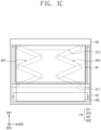
- FIG. 1c is a front view of the display device DD according to an embodiment of the present disclosure.
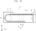
- FIG. 1d is a side view of the display device DD according to an embodiment of the present disclosure.
- the display device DD may include a display module DM, a supporter SPT, a roller ROL, a holder HD, and a housing HS.
- the display device DD may further include additional components.
- FIGS. 1a to 1c show the display device DD in a state (hereinafter, referred to as a first state) in which the display module DM is accommodated in the housing HS.
- a portion of the display module DM of the display device DD may be exposed without being covered by the housing HS in the first state(i.e., when the display device DD is in the first state), however, it should not be limited thereto or thereby.
- the display module DM may be completely inserted into the housing HS in the first state.
- the display module DM exposed without being covered by the housing HS may provide a flat display surface DD-IS.
- the display surface DD-IS may be parallel to a plane defined by a first directional axis DR1 and a second directional axis DR2.
- a third directional axis DR3 may indicate a normal line direction of the display surface DD-IS, i.e., a thickness direction of the display module DM.
- Front (or upper) and rear (or lower) surfaces of each member are distinguished from each other by the third directional axis DR3.
- the display module DM may include an organic light emitting display panel or an inorganic light emitting display panel.
- the display module DM may further include a touch panel disposed on the display panel.
- the touch panel may be disposed directly on the display panel or may be attached to the display panel by an adhesive layer.
- the touch panel may be omitted.
- the display module DM may further include a window disposed on the touch panel.
- the window may include a plastic or glass material.
- the supporter SPT may be disposed on a rear surface of the display module DM and may guide the display module DM operated in the first or second state.
- the supporter SPT may include a support film SP and a frame FR.
- the support film SP may be accommodated in the housing HS in the first state, and the support film SP may be unrolled from the housing HS to the first direction DR1 in the second state to support the display module DM.
- a portion of the support film SP may be accommodated in the housing HS regardless of the first state and the second state.
- the support film SP may be coupled to the roller ROL in the first direction DR1, and another one side(or the other side) of the support film SP may be coupled to the holder HD in the first direction DR1.
- the support film SP may include a plurality of films.
- FIGS. 1b to 1c show a first film SP1 and a second film SP2 disposed with the frame FR interposed therebetween.
- the second film SP2 may be disposed under the frame FR and may be disposed farther from the display module DM than the first film SP1 is.
- the support film SP may include a metal, plastic, or fiber material.
- the support film SP including the metal material may have a thickness equal to or smaller than about 100 micrometers, and the support film SP including the plastic or fiber material may have a thickness equal to or smaller than about 200 micrometers.
- the frame FR may shrink to a first shape in the first state and may expand to a second shape in the second state.
- the frame FR may include a first support frame CF1, a second support frame CF2, a first arm AR1, and a second arm AR2.
- the first support frame CF1 may be disposed in the housing HS regardless of the first state and the second state.
- the first support frame CF1 may be fixed to the housing HS.
- the first support frame CF1 may extend in the second direction DR2 crossing the first direction DR1.
- the second support frame CF2 may be disposed outside the housing HS at least in the second state.
- the second support frame CF2 may be disposed spaced apart from the first support frame CF1 in the first direction DR1.
- the second support frame CF2 may be disposed adjacent to the holder HD.
- the second support frame CF2 may be coupled to the holder HD.
- the first arm AR1 may connect a first side of the first support frame CF1 to a first side of the second support frame CF2, and the second arm AR2 may connect a second side of the first support frame CF1 to a second side of the second support frame CF2.
- the first side may be disposed spaced apart from the second side in the second direction DR2.
- each of the first arm AR1 and the second arm AR2 may increase a distance in the first direction DR1 between the first support frame CF1 and the second support frame CF2.
- the holder HD may be exposed to the outside of the housing HS in the first state and the second state.
- a user may pull the holder HD in the first direction DR1, and thus the supporter SPT and the display module DM may be unrolled from the housing HS.
- the display device DD may further include a driving module to unroll or roll the holder HD.
- the roller ROL may guide the support film SP and the display module DM when the state of the display device DD is changed.
- the support film SP and the display module DM wound on the roller ROL in the first state should not be limited thereto or thereby.
- the roller ROL may slide at least one selected from the support film SP and the display module DM to a storage space of the housing HS.
- the roller ROL may slide at least one selected from the support film SP and the display module DM along the first direction DR1.
- each of the support film SP and the display module DM may be transformed, for example, folded in a predetermined structure in the storage space of the housing HS.
- FIGS. 2a to 2c are views showing a change in a state of the supporter SPT according to an embodiment of the present disclosure.
- FIG. 3a is a cross-sectional view taken along a line I-I' of FIG. 2b .
- FIG. 3b is a cross-sectional view taken along a line II-II' of FIG. 2b .
- FIG. 3c is a cross-sectional view taken along a line III-III' of FIG. 2c .
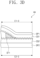
- FIG. 3d is a side view of an area AA of FIG. 2c .
- FIG. 2a shows the supporter SPT in the first state
- FIG. 2b shows the supporter SPT in a state (hereinafter, referred to as an intermediate state) between the first state and the second state
- FIG. 2c shows the supporter SPT in the second state.
- each of the first arm AR1 and the second arm AR2 may include first to n-th (n is a natural number equal to or greater than 2) joint units JU1 to JUn. In the embodiment shown in FIGS. 2a and 2b , n is 4.
- joint units adjacent to each other may be rotatably coupled to each other.
- a rotational axis RX used to couple the joint units adjacent to each other is shown.
- the rotational axis RX may include a metal material, however, it should not be particularly limited.
- the first joint unit JU1 may be rotatably coupled to the first support frame CF1, and the fourth joint unit JU4 may be rotatably coupled to the second support frame CF2.
- the first joint unit JU1 may be coupled to the first support frame CF1 using the rotational axis RX, and the fourth joint unit JU4 may be coupled to the second support frame CF2 using the rotational axis RX.
- an internal angle A1 defined by an i-th (i is a natural number equal to or greater than 1) joint unit and an (i+1)th joint unit among the first to n-th joint units is smaller than about 180 degrees
- an internal angle A2 defined by the (i+1)th joint unit and an (i+2)th joint unit may be greater than about 180 degrees.
- an internal angle A1 defined by a second joint unit JU2 and a third joint unit JU3 may be smaller than about 180 degrees
- an internal angle A2 defined by the third joint unit JU3 and the fourth joint unit JU4 may be greater than about 180 degrees.
- a first coupling area CA1 of the support film SP may be defined outside the second support frame CF2 in the first direction DR1.
- a first edge area E1-1 of the first film SP1 may be coupled to a first edge area E2-1 of the second film SP2.
- the first coupling area CA1 may be maintained in the coupling state in the first state and the second state.
- the first edge area E1-1 of the first film SP1 and the first edge area E2-1 of the second film SP2 may be coupled to each other by an adhesive layer (not shown).
- a coupling method and a coupling structure of the first edge area E1-1 of the first film SP1 and the first edge area E2-1 of the second film SP2 should not be particularly limited.
- the first coupling area CA1 may expand to an area overlapping the second support frame CF2. According to an embodiment, the first coupling area CA1 may be defined only in the area overlapping the second support frame CF2. In the above two cases, each of the first edge area E1-1 of the first film SP1 and the first edge area E2-1 of the second film SP2 may be coupled to the second support frame CF2.
- a second coupling area CA2 of the support film SP may be defined outside the first arm AR1 in the second direction DR2, and a third coupling area CA3 of the support film SP may be defined outside the second arm AR2 in the second direction DR2.
- a portion of a second edge area E1-2 of the first film SP1 may be coupled to a portion of a second edge area E2-2 of the second film SP2.
- a portion of a third edge area E1-3 of the first film SP1 may be coupled to a portion of a third edge area E2-3 of the second film SP2.
- the second coupling area CA2 and the third coupling area CA3 may be maintained in the coupled state regardless of the first state and the second state of the display device DD, and the coupling method and the coupling structure of the second coupling area CA2 and the third coupling area CA3 should not be particularly limited. According to an embodiment, the second coupling area CA2 and the third coupling area CA3 may be omitted.
- the terms "first, second, and third" are used to distinguish one edge area from another edge area, and the order of the edge areas should not be limited by the terms.
- the first edge area another one may be defined as the second edge area, and the other one may be defined as the third edge area.
- a first opening/closing area SA1 of the support film SP may be defined outside the first arm AR1 in the second direction DR2, and a second opening/closing area SA2 of the support film SP may be defined outside the second arm AR2 in the second direction DR2.
- the first opening/closing area SA1 may be continuous or integrally formed with the second coupling area CA2
- the second opening/closing area SA2 may be continuous or integrally formed with the third coupling area CA3.
- the portion of the second edge area E1-2 of the first film SP1 may be coupled to the portion of the second edge area E2-2 of the second film SP2 in the first opening/closing area SA1.
- the portion of the second edge area E1-2 of the first film SP1 and the portion of the second edge area E2-2 of the second film SP2, which are separated from each other, in the first state shown in FIG. 2a start to be coupled to each other in the intermediate state shown in FIG. 2b .
- each of the first opening/closing area SA1 and the second opening/closing area SA2 may be completely coupled in the second state shown in FIGS. 2c and 3c .
- the portion of the third edge area E1-3 of the first film SP1 and the portion of the third edge area E2-3 of the second film SP2, which are separated from each other, in the first state shown in FIG. 2a may be completely coupled to each other in the second state shown in FIGS. 2c and 3c .
- each of the first opening/closing area SA1 and the second opening/closing area SA2 may extend to the first coupling area CA1.
- a first coupling structure CS1 may be disposed in the second edge area E1-2 of the first film SP1, and a second coupling structure CS2 may be disposed in the second edge area E2-2 of the second film SP2.
- the first coupling structure CS1 may also be disposed in the third edge area E1-3 of the first film SP1, and the second coupling structure CS2 may also be disposed in the third edge area E2-3 of the second film SP2.
- the first coupling structure CS1 may be a first zipper line
- the second coupling structure CS2 may be a second zipper line that may be coupled to the first zipper line.
- the first coupling structure CS1 may be separated from the second coupling structure CS2 by the first support frame CF1 shown in FIG. 3d .
- a length in the second direction DR2 of the first support frame CF1 may be larger than a width(or a length) in the second direction DR2 of the first film SP1.
- the first support frame CF1 having the large length may be directly fixed to the housing HS as shown in FIG. 1c .
- the frame FR may further include a component that presses the first coupling structure CS1 and the second coupling structure CS2, e.g., a zipper slider.
- a component that presses the first coupling structure CS1 and the second coupling structure CS2, e.g., a zipper slider.
- the component may press the first coupling structure CS1 and the second coupling structure CS2 to allow protrusions and recesses of the first zipper line to be coupled with recesses and protrusions of the second zipper line.
- the second support frame CF2 may apply a tensile stress to the first coupling area CA1 of the support film SP along the first direction DR1.
- the first to fourth joint units JU1 to JU4 of each of the first arm AR1 and the second arm AR2 may be arranged parallel to the first direction DR1.
- the first arm AR1 and the second arm AR2 may respectively apply the tensile stress to the coupled first opening/closing area SA1 and the coupled second opening/closing area SA2 of the support film SP in the second direction DR2.
- the tension of the support film SP may increase. As the tension increases, a support force of the support film SP may be improved. Although a user's touch occurs on the display surface DD-IS (refer to FIG. 1a ) in the second state, the display module DM may not be deformed. This is because the support film SP increases the resistance of the display module DM against the external pressure.
- FIG. 4a is a side view of a coupling structure according to an embodiment of the present disclosure.
- FIG. 4b is a perspective view of a coupling structure according to an embodiment of the present disclosure.
- a first coupling structure CS1 may be a first magnetic line
- a second coupling structure CS2 may be a second magnetic line that may be coupled to the first magnetic line.
- the first magnetic line includes an N pole region and an S pole region alternately and repeatedly arranged with the N pole region
- the second magnetic line may include the S pole region and the N pole region alternately and repeatedly arranged with the S pole region.
- a component that presses the first coupling structure CS1 and the second coupling structure CS2 may be omitted.
- a first coupling structure CS1 may include a protrusion line
- a second coupling structure CS2 may include a groove line that may be coupled to the protrusion line.
- the frame FR shown in FIGS. 2a to 2c may further include a component that presses the protrusion line and the groove line.
- first coupling structure CS1 and the second coupling structure CS2 may be connected to each other with Velcro straps.
- the first coupling structure CS1 may include a velour structure
- the second coupling structure CS2 may include a crochet structure.
- FIGS. 5a to 5c are views showing a change in a state of a supporter SPT according to an embodiment of the present disclosure.
- FIGS. 1a to 4b detailed descriptions of the same elements as those in FIGS. 1a to 4b will be omitted.
- each of a first arm AR1 and a second arm AR2 may include first to n-th (n is a natural number equal to or greater than 2) joint units JU1 to JUn.
- n is 3.
- an i-th (i is a natural number equal to or greater than 2) joint unit may be coupled to an (i-1)th joint unit to be movable in the first direction DR1.
- the second and third joint units JU2 and JU3 may be inserted into the first joint unit JU1.
- the second joint unit JU2 may be slid out of the first joint unit JU1 and then may be fixed to an end of the first joint unit JU1.
- the third joint unit JU3 that moves in a similar way to the second joint unit JU2, may be fixed to an end of the second joint unit JU2.
- a coupling relation of the first arm AR1 with respect to a first support frame CF1 and a second support frame CF2 and a coupling relation of the second arm AR2 with respect to the first support frame CF1 and the second support frame CF2 are symmetrical to each other with respect to a center line ML parallel to the first direction DR1, and thus, the first arm AR1 will be mainly described.
- a first slit SL1 may be defined in the first support frame CF1, and the first joint unit JU1 may be coupled to the first slit SL1 to be movable.
- a second slit SL2 may be defined in the second support frame CF2, and the third joint unit JU3 may be coupled to the second slit SL2 to be moveable.
- the first slit SL1 may extend in a first crossing direction CDR1 crossing the first direction DR1 and the second direction DR2, and the second slit SL2 may extend in a second crossing direction CDR2 crossing the first direction DR1, the second direction DR2, and the first crossing direction CDR1.
- a distance between the first slit SL1 and the second slit SL2 may decrease as a distance from a center of the first support frame CF1 increases.
- the first arm AR1 may be disposed in an area of the first slit SL1 closest to the center of the first support frame CF1 in the first state.
- the first arm AR1 may be disposed in an area of the first slit SL1 farthest from the center of the first support frame CF1.
- the first arm AR1 and the second arm AR2 shown in FIG. 5c may apply a tensile stress to each of the first opening/closing area SA1 and the second opening/closing area SA2 of the support film SP.
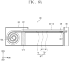
- FIG. 6a is a side view of a display device DD according to an embodiment of the present disclosure
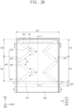
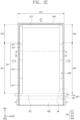
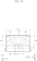
- FIG. 6b is a front view of the display device DD according to an embodiment of the present disclosure.
- detailed descriptions of the same elements as those of FIGS. 1a to 5c will be omitted.
- a frame FR may further include a third support frame CF3 that couples a first support frame CF1 to a housing HS.
- the third support frame CF3 may extend in the third direction DR3 and may be fixed to the housing HS.
- the third support frame CF3 may be provided in plural.
- a length in the second direction DR2 of the first support frame CF1 may be reduced compared with the first support frame CF1 shown in FIG. 1c .
- the length in the second direction DR2 of the first support frame CF1 may be smaller than a width in the second direction DR2 of a support film SP.
- a function of separating the coupling structure of the first support frame CF1 described with reference to FIG. 3d may be performed by the third support frame CF3. This will be described in detail later.
- a cutting line CL may be defined in a second film SP2.
- the cutting line CL may be defined at a position aligned with the third support frame CF3 in the second direction DR2 and may extend in the first direction DR1.
- the second film SP2 may include a first area SP2-1 and a second area SP2-2, which are disposed with the cutting line CL interposed therebetween in the second direction DR2.
- FIGS. 7a to 7c are views showing a change in a state of a supporter SPT according to an embodiment of the present disclosure
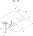
- FIG. 7d is a perspective view of a coupling structure of a second film SP2 according to an embodiment of the present disclosure.
- FIG. 7d corresponds to an area AA in FIG 7c .
- a first coupling area CA1 of a support film SP may be defined outside a second support frame CF2 in the first direction DR1.
- a second coupling area CA2 of the support film SP may be defined outside a first arm AR1 in the second direction DR2, and a third coupling area CA3 of the support film SP may be defined outside a second arm AR2 in the second direction DR2.
- the opening/closing areas SA1 and SA2 shown in FIGS. 2a to 3d may be omitted in the support film SP according to the present embodiment.
- a second edge area E1-2 (refer to FIG. 3b ) of a first film SP1 and a second edge area E2-2 (refer to FIGS. 3b and 3c ) of the second film SP2 may maintain their coupled state regardless of the state of the display device DD.
- a third edge area E1-3 of the first film SP1 and a third edge area E2-3 (refer to FIGS. 3b and 3c ) of the second film SP2 may also maintain their coupled state regardless of the state of the display device DD.
- a first area SP2-1 and a second area SP2-2 which come out from the housing HS (refer to FIG. 6a ), may increase.
- the first area SP2-1 and the second area SP2-2 which are disposed at one side of the third support frame CF3 in the first direction DR1, may be coupled to each other.
- a first coupling structure CS1 may be disposed in the first area SP2-1, and a second coupling structure CS2 may be disposed in the second area SP2-2.
- the first coupling structure CS1 and the second coupling structure CS2 may be coupled to each other when the first state is changed to the second state and may be separated from each other when the second state is changed to the first state.
- the first coupling structure CS1 may be a first zipper line
- the second coupling structure CS2 may be a second zipper line that may be coupled to the first zipper line.
- the first zipper line and the second zipper line may be coupled to each other by a zipper slider ZH and may be separated from each other by the third support frame CF3.
- the zipper slider ZH may be fixed to the housing HS (refer to FIG. 6a ).
- the second support frame CF2 may apply a tensile stress to the first coupling area CA1 of the support film SP in the first direction DR1 in the second state shown in FIG. 7c .
- the first arm AR1 and the second arm AR2 may apply the tensile stress to the second coupling area CA2 and the third coupling area CA3 of the support film SP, respectively. Since the second coupling area CA2 and the third coupling area CA3 may maintain their each coupled state regardless of the state of the display device DD, defects such as deformation due to the applied tensile stress or loosening due to the applied tensile stress may be reduced.
- FIGS. 8a to 8c are views showing a change in a state of a supporter SPT according to an embodiment of the present disclosure.
- FIGS. 6a to 7d detailed descriptions of the same elements as those of FIGS. 6a to 7d will be omitted.
- the cutting line CL described with reference to FIGS. 6a to 7d may be replaced with an opening area SP2-OP.
- An opening area SP2-OP may be defined in a second film SP2.
- a level of the tensile stress applied to a second coupling area CA2 and a third coupling area CA3 of a support film SP in a second state shown in FIG. 8c may correspond to that of the tensile stress applied to the support film SP shown in FIGS. 7a to 7c . Since the first coupling structure CS1 and the second coupling structure CS2 shown in FIG. 7d may be omitted, a manufacturing cost may be reduced, and defects occurring when the first and second coupling structures CS1 and CS2 are coupled to or separated from each other may be prevented.
- FIGS. 9a to 9c are views showing a change in a state of a display device DD according to an embodiment of the present disclosure
- FIG. 9d is a cross-sectional view taken along a line IV-IV' of FIG. 9c .
- FIGS. 1a to 8c detailed descriptions of the same elements as those of FIGS. 1a to 8c will be omitted.
- a support film SP may include only one film or single film.
- the above-described second film SP2 may be omitted, and the support film SP may include only a first film SP1.
- the support film SP may be coupled to a second support frame CF2.
- a first edge area E1 of the support film SP may be coupled to the second support frame CF2.
- FIGS. 9a to 9c show the second support frame CF2 of which length in the first direction DR1 increases to overlap the first edge area E1 of the support film SP in order to secure a first coupling area CA1.
- a first coupling structure CS1 may be disposed on the support film SP.
- the first coupling structure CS1 may include a metal layer disposed in a second edge area E2 and a third edge area E3 of the support film SP.
- the first coupling structure CS1 may be formed by coating or depositing a metal material on one surface of the support film SP.
- a width in the second direction DR2 of the metal layer may correspond to a width of first to fourth joint units JU1 to JU4.
- a second coupling structure CS2 may be disposed in each of a first arm AR1 and a second arm AR2.
- the second coupling structure CS2 may include a magnet or an electromagnet.
- the second coupling structure CS2 may be disposed in each of the first to fourth joint units JU1 to JU4.
- the magnet or electromagnet may be disposed on an upper surface of each of the first to fourth joint units JU1 to JU4.
- a cavity may be defined or formed in each of the first to fourth joint units JU1 to JU4 to accommodate the magnet or electromagnet.
- FIG. 9d shows a cross-section of a coupled state of the first coupling structure CS1 and the second coupling structure CS2.
- a tensile stress may occur in the support film SP.
- a support force of the support film SP may increase.
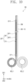
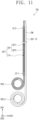
- FIGS. 10 and 11 are side views of a display device DD according to an embodiment of the present disclosure.
- the holder HD and the housing HS are not shown.
- the display device DD may include a plurality of rollers.
- a support film SP may be wound on a first roller ROL1
- a display module DM may be wound on a second roller ROL2.
- interference defects that occur in a process of winding the support film SP and the display module DM on one roller may be prevented.
- first roller ROL1 and the second roller ROL2 may be disposed spaced apart from each other in the third direction DR3.
- first roller ROL1 and the second roller ROL2 may be disposed spaced apart from each other in the first direction DR1.
Landscapes
- Engineering & Computer Science (AREA)
- Theoretical Computer Science (AREA)
- Computer Hardware Design (AREA)
- Physics & Mathematics (AREA)
- General Engineering & Computer Science (AREA)
- General Physics & Mathematics (AREA)
- Human Computer Interaction (AREA)
- Signal Processing (AREA)
- Mathematical Physics (AREA)
- Devices For Indicating Variable Information By Combining Individual Elements (AREA)
Abstract
Description
- The present disclosure relates to a display device. More particularly, the present disclosure relates to a rollable display device.
- Electronic devices, such as smartphones, tablet computers, notebook computers, car navigation units, and smart televisions, are being developed. The electronic devices include a display device to provide information.
- Various types of display devices are being developed to satisfy the user experience UX and the user interface UI. Among them, flexible display devices are being actively developed.
- The present disclosure provides a display device having improved resistance against an external pressure.
- Embodiments of the inventive concept provide a display device including a housing, a display module accommodated in the housing in a first state and unrolled from the housing to a first direction in a second state, a support film accommodated in the housing in the first state and unrolled from the housing to the first direction in the second state to support the display module, and a frame shrinking to a first shape in the first state and expanding to a second shape in the second state to apply a tensile stress to the support film.
- The tensile stress is applied in the first direction and a second direction crossing the first direction.
- The support film includes a first film and a second film disposed spaced apart from the first film with the frame interposed therebetween and disposed farther from the display module than the first film is.
- The frame includes a first support frame disposed in the housing in the second state and extending in the second direction crossing the first direction, a second support frame disposed outside the housing in the second state and disposed spaced apart from the first support frame in the first direction, a first arm connecting a first side of the first support frame to a first side of the second support frame, and a second arm connecting a second side of the first support frame to a second side of the second support frame, and a distance in the first direction between the first support frame and the second support frame increases by the first arm and the second arm when the first state is changed to the second state.
- Each of the first arm and the second arm includes first to n-th (n is a natural number equal to or greater than 2) joint units, and joint units adjacent to each other among the first to n-th joint units are rotatably coupled to each other.
- An internal angle defined by an (i+1)th (i is a natural number equal to or greater than 1) joint unit and an (i+2)th joint unit is greater than about 180 degrees in the first state when an internal angle defined by an i-th joint unit and the (i+1)th joint unit among the first to n-th joint units is smaller than about 180 degrees in the first state.
- Each of the first to n-th joint units is aligned parallel to the first direction in the second state.
- Each of the first arm and the second arm includes first to n-th (n is a natural number equal to or greater than 2) joint units, and among the first to n-th joint units, an i-th (i is a natural number equal to or greater than 2) joint unit is coupled to an (i-1)th joint unit to be movable in the first direction in the second state.
- The first support frame is provided with a first slit defined therein, the first joint unit is coupled to the first slit to be movable, the second support frame is provided with a second slit defined therein, and the n-th joint unit is coupled to the second slit to be movable.
- The first slit extends in a first crossing direction crossing the first direction and the second direction, the second slit extends in a second crossing direction crossing the first direction, the second direction, and the first crossing direction, and a distance between the first slit and the second slit decreases as a distance from a center of the first support frame increases.
- An edge area of the first film and an edge area of the second film, which are disposed outside the second support frame in the first direction, are coupled to each other in the first state and the second state.
- A first edge area of the first film and a first edge area of the second film, which are disposed outside the first arm in the second direction, are separated from each other in the first state and are coupled to each other in the second state, and a second edge area of the first film and a second edge area of the second film, which are disposed outside the second arm in the second direction, are separated from each other in the first state and are coupled to each other in the second state
- The display device further includes a first coupling structure disposed in the first edge area of the first film and a second coupling structure disposed in the first edge area of the second film, and the first coupling structure and the second coupling structure are separated from each other in the first state and are coupled to each other in the second state.
- The first coupling structure and the second coupling structure are separated from each other by the first support frame when a state of the support film is changed from the second state to the first state.
- A length in the second direction of the first support frame is greater than a width in the second direction of the first film, and the first support frame is installed in the housing.
- A first edge area of the first film and a first edge area of the second film, which are adjacent to the second support frame in the first direction, are coupled to each other in the first state and the second state, a second edge area of the first film and a second edge area of the second film, which are disposed outside the first arm in the second direction, are coupled to each other in the first state and the second state, and a third edge area of the first film and a third edge area of the second film, which are disposed outside the second arm in the second direction, are coupled to each other in the first state and the second state.
- The display device further includes a third support frame to fix the first support frame to the housing, the second film is provided with a cutting line defined therein and aligned with the third support frame, the second film includes a first area and a second area arranged with the cutting line interposed therebetween in the second direction, and the first area and the second area are separated from each other in the first state and coupled to each other in the second state.
- The display device further includes a first coupling structure disposed in the first area and a second coupling structure disposed in the second area, and the first coupling structure and the second coupling structure are separated from each other in the first state and are coupled to each other in the second state.
- The first coupling structure and the second coupling structure are separated from each other by the third support frame when a state of the second film is changed from the second state to the first state.
- The display device further includes a third support frame to fix the first support frame to the housing, and the second film is provided with an opening area, and the third support frame is disposed in the opening area.
- The display device further includes first coupling structures coupled to the support film.
- The frame includes a first support frame disposed in the housing in the second state and extending in a second direction crossing the first direction, a second support frame disposed outside the housing in the second state and disposed spaced apart from the first support frame in the first direction, a first arm connecting a first side of the first support frame to a first side of the second support frame, a second arm connecting a second side of the first support frame to a second side of the second support frame, and second coupling structures respectively disposed in the first arm and the second arm, a distance in the first direction between the first support frame and the second support frame increases by the first arm and the second arm when the first state is changed to the second state, and the first coupling structures are respectively coupled to the second coupling structures in the second state.
- The support film includes a first edge area and a second edge area facing the first edge area in the second direction, the first coupling structures include a metal layer disposed in the first edge area and the second edge area, and the second coupling structures include a magnet or an electromagnet.
- Each of the first film and the second film includes a plastic, metal, or fiber material.
- The display device further includes at least one roller installed in the housing, and the support film is wound on the roller in the first state.
- The display module is wound on the roller in the first state.
- The roller includes a first roller and a second roller, the support film is wound on the first roller in the first state, and the display module is wound on the second roller in the first state.
- According to the above, the frame applies a tensile stress to the support film when the display module is unrolled and flat. As a tension of the support film increases due to the tensile stress, the support force of the support film is improved. Accordingly, even though a touch event occurs on the display module by a user, the display module is prevented from being deformed.
- Different from a multi-joint supporter or a support block, the support film does not apply a local compressive stress to the display module when the display module is wound on the roller. Thus, defects related to the surface quality caused by the deformation of the display module are prevented.
-
-
FIG. 1a is a perspective view of a display device according to an embodiment of the present disclosure; -
FIG. 1b is a side view of a display device according to an embodiment of the present disclosure; -
FIG. 1c is a front view of a display device according to an embodiment of the present disclosure; -
FIG. 1d is a side view of a display device according to an embodiment of the present disclosure; -
FIGS. 2a to 2c are views showing a change in a state of a supporter according to an embodiment of the present disclosure; -
FIG. 3a is a cross-sectional view taken along a line I-I' ofFIG. 2b ; -
FIG. 3b is a cross-sectional view taken along a line II-II' ofFIG. 2b ; -
FIG. 3c is a cross-sectional view taken along a line III-III' ofFIG. 2c ; -
FIG. 3d is a side view of an area ofFIG. 2c ; -
FIG. 4a is a side view of a coupling structure according to an embodiment of the present disclosure; -
FIG. 4b is a perspective view of a coupling structure according to an embodiment of the present disclosure; -
FIGS. 5a to 5c are views showing a change in a state of a supporter according to an embodiment of the present disclosure; -
FIG. 6a is a side view of a display device according to an embodiment of the present disclosure; -
FIG. 6b is a front view of a display device according to an embodiment of the present disclosure; -
FIGS. 7a to 7c are views showing a change in a state of a supporter according to an embodiment of the present disclosure; -
FIG. 7d is a perspective view of a coupling structure of a second film according to an embodiment of the present disclosure; -
FIGS. 8a to 8c are views showing a change in a state of a supporter according to an embodiment of the present disclosure; -
FIGS. 9a to 9c are views showing a change in a state of a supporter according to an embodiment of the present disclosure; -
FIG. 9d is a cross-sectional view taken along a line IV-IV' ofFIG. 9c ; and -
FIGS. 10 and11 are side views of a display device according to an embodiment of the present disclosure. - In the present disclosure, it will be understood that when an element (or area, layer, or portion) is referred to as being "on", "connected to" or "coupled to" another element or layer, it can be directly on, connected or coupled to the other element or layer or intervening elements or layers may be present.
- Like numerals refer to like elements throughout. In the drawings, the thickness, ratio, and dimension of components are exaggerated for effective description of the technical content. As used herein, the term "and/or" includes any and all combinations of one or more of the associated listed items.
- It will be understood that, although the terms first, second, etc. may be used herein to describe various elements, these elements should not be limited by these terms. These terms are only used to distinguish one element from another element. Thus, a first element discussed below could be termed a second element without departing from the teachings of the present disclosure. As used herein, the singular forms, "a", "an" and "the" are intended to include the plural forms as well, unless the context clearly indicates otherwise.
- Spatially relative terms, such as "beneath", "below", "lower", "above", "upper" and the like, may be used herein for ease of description to describe one element or feature's relationship to another element(s) or feature(s) as illustrated in the figures.
- It will be further understood that the terms "includes" and/or "including", when used in this specification, specify the presence of stated features, integers, steps, operations, elements, and/or components, but do not preclude the presence or addition of one or more other features, integers, steps, operations, elements, components, and/or groups thereof.
- Unless otherwise defined, all terms (including technical and scientific terms) used herein have the same meaning as commonly understood by one of ordinary skill in the art to which this disclosure belongs. It will be further understood that terms, such as those defined in commonly used dictionaries, should be interpreted as having a meaning that is consistent with their meaning in the context of the relevant art and will not be interpreted in an idealized or overly formal sense unless expressly so defined herein.
- Hereinafter, the present disclosure will be explained in detail with reference to the accompanying drawings.
-
FIG. 1a is a perspective view of a display device DD according to an embodiment of the present disclosure.FIG. 1b is a side view of the display device DD according to an embodiment of the present disclosure.FIG. 1c is a front view of the display device DD according to an embodiment of the present disclosure.FIG. 1d is a side view of the display device DD according to an embodiment of the present disclosure. - Referring to
FIGS. 1a to 1c , the display device DD may include a display module DM, a supporter SPT, a roller ROL, a holder HD, and a housing HS. The display device DD may further include additional components. -
FIGS. 1a to 1c show the display device DD in a state (hereinafter, referred to as a first state) in which the display module DM is accommodated in the housing HS. A portion of the display module DM of the display device DD may be exposed without being covered by the housing HS in the first state(i.e., when the display device DD is in the first state), however, it should not be limited thereto or thereby. According to an embodiment, the display module DM may be completely inserted into the housing HS in the first state. - In a state (hereinafter, referred to as a second state) in which the display module DM is fully unfolded, the display module DM exposed without being covered by the housing HS may provide a flat display surface DD-IS. The display surface DD-IS may be parallel to a plane defined by a first directional axis DR1 and a second directional axis DR2. A third directional axis DR3 may indicate a normal line direction of the display surface DD-IS, i.e., a thickness direction of the display module DM. Front (or upper) and rear (or lower) surfaces of each member are distinguished from each other by the third directional axis DR3.
- The display module DM may include an organic light emitting display panel or an inorganic light emitting display panel. The display module DM may further include a touch panel disposed on the display panel. The touch panel may be disposed directly on the display panel or may be attached to the display panel by an adhesive layer. The touch panel may be omitted. The display module DM may further include a window disposed on the touch panel. The window may include a plastic or glass material.
- The supporter SPT may be disposed on a rear surface of the display module DM and may guide the display module DM operated in the first or second state. The supporter SPT may include a support film SP and a frame FR. The support film SP may be accommodated in the housing HS in the first state, and the support film SP may be unrolled from the housing HS to the first direction DR1 in the second state to support the display module DM. A portion of the support film SP may be accommodated in the housing HS regardless of the first state and the second state.
- One side of the support film SP may be coupled to the roller ROL in the first direction DR1, and another one side(or the other side) of the support film SP may be coupled to the holder HD in the first direction DR1. The support film SP may include a plurality of films.
FIGS. 1b to 1c show a first film SP1 and a second film SP2 disposed with the frame FR interposed therebetween. The second film SP2 may be disposed under the frame FR and may be disposed farther from the display module DM than the first film SP1 is. - The support film SP may include a metal, plastic, or fiber material. The support film SP including the metal material may have a thickness equal to or smaller than about 100 micrometers, and the support film SP including the plastic or fiber material may have a thickness equal to or smaller than about 200 micrometers.
- The frame FR may shrink to a first shape in the first state and may expand to a second shape in the second state. The frame FR may include a first support frame CF1, a second support frame CF2, a first arm AR1, and a second arm AR2. The first support frame CF1 may be disposed in the housing HS regardless of the first state and the second state. The first support frame CF1 may be fixed to the housing HS. The first support frame CF1 may extend in the second direction DR2 crossing the first direction DR1. The second support frame CF2 may be disposed outside the housing HS at least in the second state. The second support frame CF2 may be disposed spaced apart from the first support frame CF1 in the first direction DR1. The second support frame CF2 may be disposed adjacent to the holder HD. The second support frame CF2 may be coupled to the holder HD.
- The first arm AR1 may connect a first side of the first support frame CF1 to a first side of the second support frame CF2, and the second arm AR2 may connect a second side of the first support frame CF1 to a second side of the second support frame CF2. The first side may be disposed spaced apart from the second side in the second direction DR2. When the first state is switched to the second state, each of the first arm AR1 and the second arm AR2 may increase a distance in the first direction DR1 between the first support frame CF1 and the second support frame CF2.
- The holder HD may be exposed to the outside of the housing HS in the first state and the second state. A user may pull the holder HD in the first direction DR1, and thus the supporter SPT and the display module DM may be unrolled from the housing HS. The display device DD may further include a driving module to unroll or roll the holder HD.
- The roller ROL may guide the support film SP and the display module DM when the state of the display device DD is changed. The support film SP and the display module DM wound on the roller ROL in the first state, however, the present disclosure should not be limited thereto or thereby.
- As shown in
FIG. 1d , the roller ROL may slide at least one selected from the support film SP and the display module DM to a storage space of the housing HS. As the state of the display device DD is changed from the first state to the second state or vice versa, the roller ROL may slide at least one selected from the support film SP and the display module DM along the first direction DR1. Although not shown in figures, each of the support film SP and the display module DM may be transformed, for example, folded in a predetermined structure in the storage space of the housing HS. -
FIGS. 2a to 2c are views showing a change in a state of the supporter SPT according to an embodiment of the present disclosure.FIG. 3a is a cross-sectional view taken along a line I-I' ofFIG. 2b .FIG. 3b is a cross-sectional view taken along a line II-II' ofFIG. 2b .FIG. 3c is a cross-sectional view taken along a line III-III' ofFIG. 2c .FIG. 3d is a side view of an area AA ofFIG. 2c . -
FIG. 2a shows the supporter SPT in the first state,FIG. 2b shows the supporter SPT in a state (hereinafter, referred to as an intermediate state) between the first state and the second state, andFIG. 2c shows the supporter SPT in the second state. Some components of the display device DD shown inFIGS. 1a to 1c are not shown inFIGS. 2a to 2c . - Referring to
FIGS. 2a and2b , each of the first arm AR1 and the second arm AR2 may include first to n-th (n is a natural number equal to or greater than 2) joint units JU1 to JUn. In the embodiment shown inFIGS. 2a and2b , n is 4. - Among the first to fourth joint units JU1 to JU4, joint units adjacent to each other may be rotatably coupled to each other. A rotational axis RX used to couple the joint units adjacent to each other is shown. The rotational axis RX may include a metal material, however, it should not be particularly limited.
- The first joint unit JU1 may be rotatably coupled to the first support frame CF1, and the fourth joint unit JU4 may be rotatably coupled to the second support frame CF2. The first joint unit JU1 may be coupled to the first support frame CF1 using the rotational axis RX, and the fourth joint unit JU4 may be coupled to the second support frame CF2 using the rotational axis RX.
- When an internal angle A1 defined by an i-th (i is a natural number equal to or greater than 1) joint unit and an (i+1)th joint unit among the first to n-th joint units is smaller than about 180 degrees, an internal angle A2 defined by the (i+1)th joint unit and an (i+2)th joint unit may be greater than about 180 degrees. For instance, according to
FIG. 2b , an internal angle A1 defined by a second joint unit JU2 and a third joint unit JU3 may be smaller than about 180 degrees, and an internal angle A2 defined by the third joint unit JU3 and the fourth joint unit JU4 may be greater than about 180 degrees. - Referring to
FIGS. 2b and3a , a first coupling area CA1 of the support film SP may be defined outside the second support frame CF2 in the first direction DR1. In the first coupling area CA1, a first edge area E1-1 of the first film SP1 may be coupled to a first edge area E2-1 of the second film SP2. The first coupling area CA1 may be maintained in the coupling state in the first state and the second state. - The first edge area E1-1 of the first film SP1 and the first edge area E2-1 of the second film SP2 may be coupled to each other by an adhesive layer (not shown). A coupling method and a coupling structure of the first edge area E1-1 of the first film SP1 and the first edge area E2-1 of the second film SP2 should not be particularly limited.
- According to an embodiment, the first coupling area CA1 may expand to an area overlapping the second support frame CF2. According to an embodiment, the first coupling area CA1 may be defined only in the area overlapping the second support frame CF2. In the above two cases, each of the first edge area E1-1 of the first film SP1 and the first edge area E2-1 of the second film SP2 may be coupled to the second support frame CF2.
- Referring to
FIGS. 2b and3b , a second coupling area CA2 of the support film SP may be defined outside the first arm AR1 in the second direction DR2, and a third coupling area CA3 of the support film SP may be defined outside the second arm AR2 in the second direction DR2. In the second coupling area CA2, a portion of a second edge area E1-2 of the first film SP1 may be coupled to a portion of a second edge area E2-2 of the second film SP2. In the third coupling area CA3, a portion of a third edge area E1-3 of the first film SP1 may be coupled to a portion of a third edge area E2-3 of the second film SP2. The second coupling area CA2 and the third coupling area CA3 may be maintained in the coupled state regardless of the first state and the second state of the display device DD, and the coupling method and the coupling structure of the second coupling area CA2 and the third coupling area CA3 should not be particularly limited. According to an embodiment, the second coupling area CA2 and the third coupling area CA3 may be omitted. - Meanwhile, in describing the edge areas, e.g., the first edge area E1-1, E2-1 the second edge area E1-2, E2-2, and the third edge area E1-3, E2-3, the terms "first, second, and third" are used to distinguish one edge area from another edge area, and the order of the edge areas should not be limited by the terms. When any one is defined as the first edge area, another one may be defined as the second edge area, and the other one may be defined as the third edge area.
- Referring to
FIG. 2c , a first opening/closing area SA1 of the support film SP may be defined outside the first arm AR1 in the second direction DR2, and a second opening/closing area SA2 of the support film SP may be defined outside the second arm AR2 in the second direction DR2. The first opening/closing area SA1 may be continuous or integrally formed with the second coupling area CA2, and the second opening/closing area SA2 may be continuous or integrally formed with the third coupling area CA3. - Referring to
FIGS. 2c and3c , the portion of the second edge area E1-2 of the first film SP1 may be coupled to the portion of the second edge area E2-2 of the second film SP2 in the first opening/closing area SA1. The portion of the second edge area E1-2 of the first film SP1 and the portion of the second edge area E2-2 of the second film SP2, which are separated from each other, in the first state shown inFIG. 2a start to be coupled to each other in the intermediate state shown inFIG. 2b . Then, each of the first opening/closing area SA1 and the second opening/closing area SA2 may be completely coupled in the second state shown inFIGS. 2c and3c . The portion of the third edge area E1-3 of the first film SP1 and the portion of the third edge area E2-3 of the second film SP2, which are separated from each other, in the first state shown inFIG. 2a may be completely coupled to each other in the second state shown inFIGS. 2c and3c . In the case where the second coupling area CA2 and the third coupling area CA3 are omitted, each of the first opening/closing area SA1 and the second opening/closing area SA2 may extend to the first coupling area CA1. - As shown in
FIG. 3c , a first coupling structure CS1 may be disposed in the second edge area E1-2 of the first film SP1, and a second coupling structure CS2 may be disposed in the second edge area E2-2 of the second film SP2. The first coupling structure CS1 may also be disposed in the third edge area E1-3 of the first film SP1, and the second coupling structure CS2 may also be disposed in the third edge area E2-3 of the second film SP2. - As shown in
FIG. 3d , the first coupling structure CS1 may be a first zipper line, and the second coupling structure CS2 may be a second zipper line that may be coupled to the first zipper line. When the first film SP1 and the second film SP2 are changed from in the second state shown inFIG. 2c to in the first state shown inFIG. 2a , the first coupling structure CS1 may be separated from the second coupling structure CS2 by the first support frame CF1 shown inFIG. 3d . - As shown in
FIGS. 2a to 2c , a length in the second direction DR2 of the first support frame CF1 may be larger than a width(or a length) in the second direction DR2 of the first film SP1. The first support frame CF1 having the large length may be directly fixed to the housing HS as shown inFIG. 1c . - Although not shown in figures, the frame FR may further include a component that presses the first coupling structure CS1 and the second coupling structure CS2, e.g., a zipper slider. When the first film SP1 and the second film SP2 are changed from in the first state shown in
FIG. 2a to in the second state shown inFIG. 2c , the component may press the first coupling structure CS1 and the second coupling structure CS2 to allow protrusions and recesses of the first zipper line to be coupled with recesses and protrusions of the second zipper line. - Referring to
FIG. 2c again, in the second state in which the frame FR is completely unrolled, the second support frame CF2 may apply a tensile stress to the first coupling area CA1 of the support film SP along the first direction DR1. In the second state, the first to fourth joint units JU1 to JU4 of each of the first arm AR1 and the second arm AR2 may be arranged parallel to the first direction DR1. The first arm AR1 and the second arm AR2 may respectively apply the tensile stress to the coupled first opening/closing area SA1 and the coupled second opening/closing area SA2 of the support film SP in the second direction DR2. - As the tensile stress is applied along the first direction DR1 and the second direction DR2, the tension of the support film SP may increase. As the tension increases, a support force of the support film SP may be improved. Although a user's touch occurs on the display surface DD-IS (refer to
FIG. 1a ) in the second state, the display module DM may not be deformed. This is because the support film SP increases the resistance of the display module DM against the external pressure. -
FIG. 4a is a side view of a coupling structure according to an embodiment of the present disclosure.FIG. 4b is a perspective view of a coupling structure according to an embodiment of the present disclosure. Hereinafter, detailed descriptions of the same elements as those inFIGS. 3a to 3d will be omitted. - Referring to
FIG. 4a , a first coupling structure CS1 may be a first magnetic line, and a second coupling structure CS2 may be a second magnetic line that may be coupled to the first magnetic line. When the first magnetic line includes an N pole region and an S pole region alternately and repeatedly arranged with the N pole region, the second magnetic line may include the S pole region and the N pole region alternately and repeatedly arranged with the S pole region. A component that presses the first coupling structure CS1 and the second coupling structure CS2 may be omitted. - Referring to
FIG. 4b , a first coupling structure CS1 may include a protrusion line, and a second coupling structure CS2 may include a groove line that may be coupled to the protrusion line. The frame FR shown inFIGS. 2a to 2c may further include a component that presses the protrusion line and the groove line. - Although not shown in figures, the first coupling structure CS1 and the second coupling structure CS2 may be connected to each other with Velcro straps. The first coupling structure CS1 may include a velour structure, and the second coupling structure CS2 may include a crochet structure.
-
FIGS. 5a to 5c are views showing a change in a state of a supporter SPT according to an embodiment of the present disclosure. Hereinafter, detailed descriptions of the same elements as those inFIGS. 1a to 4b will be omitted. - Referring to
FIGS. 5a to 5c , each of a first arm AR1 and a second arm AR2 may include first to n-th (n is a natural number equal to or greater than 2) joint units JU1 to JUn. In the embodiment shown inFIGS. 5a to 5c , n is 3. Among the first, second, and third joint units, an i-th (i is a natural number equal to or greater than 2) joint unit may be coupled to an (i-1)th joint unit to be movable in the first direction DR1. In a first state, the second and third joint units JU2 and JU3 may be inserted into the first joint unit JU1. In a second state, the second joint unit JU2 may be slid out of the first joint unit JU1 and then may be fixed to an end of the first joint unit JU1. The third joint unit JU3 that moves in a similar way to the second joint unit JU2, may be fixed to an end of the second joint unit JU2. - A coupling relation of the first arm AR1 with respect to a first support frame CF1 and a second support frame CF2 and a coupling relation of the second arm AR2 with respect to the first support frame CF1 and the second support frame CF2 are symmetrical to each other with respect to a center line ML parallel to the first direction DR1, and thus, the first arm AR1 will be mainly described.
- A first slit SL1 may be defined in the first support frame CF1, and the first joint unit JU1 may be coupled to the first slit SL1 to be movable. A second slit SL2 may be defined in the second support frame CF2, and the third joint unit JU3 may be coupled to the second slit SL2 to be moveable.
- The first slit SL1 may extend in a first crossing direction CDR1 crossing the first direction DR1 and the second direction DR2, and the second slit SL2 may extend in a second crossing direction CDR2 crossing the first direction DR1, the second direction DR2, and the first crossing direction CDR1. A distance between the first slit SL1 and the second slit SL2 may decrease as a distance from a center of the first support frame CF1 increases.
- As shown in
FIG. 5a , the first arm AR1 may be disposed in an area of the first slit SL1 closest to the center of the first support frame CF1 in the first state. In the second state shown inFIG. 5c following an intermediate state shown inFIG. 5b , the first arm AR1 may be disposed in an area of the first slit SL1 farthest from the center of the first support frame CF1. - As described with reference to
FIG. 2c , the first arm AR1 and the second arm AR2 shown inFIG. 5c may apply a tensile stress to each of the first opening/closing area SA1 and the second opening/closing area SA2 of the support film SP. -
FIG. 6a is a side view of a display device DD according to an embodiment of the present disclosure, andFIG. 6b is a front view of the display device DD according to an embodiment of the present disclosure. Hereinafter, detailed descriptions of the same elements as those ofFIGS. 1a to 5c will be omitted. - Referring to
FIG. 6a , a frame FR may further include a third support frame CF3 that couples a first support frame CF1 to a housing HS. The third support frame CF3 may extend in the third direction DR3 and may be fixed to the housing HS. The third support frame CF3 may be provided in plural. - Referring to
FIG. 6B , a length in the second direction DR2 of the first support frame CF1 may be reduced compared with the first support frame CF1 shown inFIG. 1c . The length in the second direction DR2 of the first support frame CF1 may be smaller than a width in the second direction DR2 of a support film SP. A function of separating the coupling structure of the first support frame CF1 described with reference toFIG. 3d may be performed by the third support frame CF3. This will be described in detail later. - A cutting line CL may be defined in a second film SP2. The cutting line CL may be defined at a position aligned with the third support frame CF3 in the second direction DR2 and may extend in the first direction DR1. The second film SP2 may include a first area SP2-1 and a second area SP2-2, which are disposed with the cutting line CL interposed therebetween in the second direction DR2.
-
FIGS. 7a to 7c are views showing a change in a state of a supporter SPT according to an embodiment of the present disclosure, andFIG. 7d is a perspective view of a coupling structure of a second film SP2 according to an embodiment of the present disclosure.FIG. 7d corresponds to an area AA inFIG 7c . - Referring to
FIGS. 7a to 7c , a first coupling area CA1 of a support film SP may be defined outside a second support frame CF2 in the first direction DR1. A second coupling area CA2 of the support film SP may be defined outside a first arm AR1 in the second direction DR2, and a third coupling area CA3 of the support film SP may be defined outside a second arm AR2 in the second direction DR2. - The opening/closing areas SA1 and SA2 shown in
FIGS. 2a to 3d may be omitted in the support film SP according to the present embodiment. A second edge area E1-2 (refer toFIG. 3b ) of a first film SP1 and a second edge area E2-2 (refer toFIGS. 3b and3c ) of the second film SP2 may maintain their coupled state regardless of the state of the display device DD. A third edge area E1-3 of the first film SP1 and a third edge area E2-3 (refer toFIGS. 3b and3c ) of the second film SP2 may also maintain their coupled state regardless of the state of the display device DD. - As a first state shown in
FIG. 7a is changed to a second state shown inFIG. 7c , a first area SP2-1 and a second area SP2-2, which come out from the housing HS (refer toFIG. 6a ), may increase. The first area SP2-1 and the second area SP2-2, which are disposed at one side of the third support frame CF3 in the first direction DR1, may be coupled to each other. - Referring to
FIG. 7d , a first coupling structure CS1 may be disposed in the first area SP2-1, and a second coupling structure CS2 may be disposed in the second area SP2-2. The first coupling structure CS1 and the second coupling structure CS2 may be coupled to each other when the first state is changed to the second state and may be separated from each other when the second state is changed to the first state. In the present embodiment, the first coupling structure CS1 may be a first zipper line, and the second coupling structure CS2 may be a second zipper line that may be coupled to the first zipper line. - The first zipper line and the second zipper line may be coupled to each other by a zipper slider ZH and may be separated from each other by the third support frame CF3. Although not shown in figures, the zipper slider ZH may be fixed to the housing HS (refer to
FIG. 6a ). - According to the present embodiment, the second support frame CF2 may apply a tensile stress to the first coupling area CA1 of the support film SP in the first direction DR1 in the second state shown in
FIG. 7c . The first arm AR1 and the second arm AR2 may apply the tensile stress to the second coupling area CA2 and the third coupling area CA3 of the support film SP, respectively. Since the second coupling area CA2 and the third coupling area CA3 may maintain their each coupled state regardless of the state of the display device DD, defects such as deformation due to the applied tensile stress or loosening due to the applied tensile stress may be reduced. -
FIGS. 8a to 8c are views showing a change in a state of a supporter SPT according to an embodiment of the present disclosure. Hereinafter, detailed descriptions of the same elements as those ofFIGS. 6a to 7d will be omitted. - According to the present embodiment, the cutting line CL described with reference to
FIGS. 6a to 7d may be replaced with an opening area SP2-OP. An opening area SP2-OP may be defined in a second film SP2. - A level of the tensile stress applied to a second coupling area CA2 and a third coupling area CA3 of a support film SP in a second state shown in
FIG. 8c may correspond to that of the tensile stress applied to the support film SP shown inFIGS. 7a to 7c . Since the first coupling structure CS1 and the second coupling structure CS2 shown inFIG. 7d may be omitted, a manufacturing cost may be reduced, and defects occurring when the first and second coupling structures CS1 and CS2 are coupled to or separated from each other may be prevented. -
FIGS. 9a to 9c are views showing a change in a state of a display device DD according to an embodiment of the present disclosure, andFIG. 9d is a cross-sectional view taken along a line IV-IV' ofFIG. 9c . Hereinafter, detailed descriptions of the same elements as those ofFIGS. 1a to 8c will be omitted. - According to the present embodiment, a support film SP may include only one film or single film. For instance, the above-described second film SP2 may be omitted, and the support film SP may include only a first film SP1.
- The support film SP may be coupled to a second support frame CF2. A first edge area E1 of the support film SP may be coupled to the second support frame CF2.
FIGS. 9a to 9c show the second support frame CF2 of which length in the first direction DR1 increases to overlap the first edge area E1 of the support film SP in order to secure a first coupling area CA1. - A first coupling structure CS1 may be disposed on the support film SP. The first coupling structure CS1 may include a metal layer disposed in a second edge area E2 and a third edge area E3 of the support film SP. The first coupling structure CS1 may be formed by coating or depositing a metal material on one surface of the support film SP. A width in the second direction DR2 of the metal layer may correspond to a width of first to fourth joint units JU1 to JU4.
- A second coupling structure CS2 may be disposed in each of a first arm AR1 and a second arm AR2. The second coupling structure CS2 may include a magnet or an electromagnet. The second coupling structure CS2 may be disposed in each of the first to fourth joint units JU1 to JU4. The magnet or electromagnet may be disposed on an upper surface of each of the first to fourth joint units JU1 to JU4. A cavity may be defined or formed in each of the first to fourth joint units JU1 to JU4 to accommodate the magnet or electromagnet.
- In a second state shown in
FIG. 9c , the metal layer of the second edge area E2 may be coupled to the magnet or electromagnet of the first arm AR1, and the metal layer of the third edge area E3 may be coupled to the magnet or electromagnet of the second arm AR2.FIG. 9d shows a cross-section of a coupled state of the first coupling structure CS1 and the second coupling structure CS2. - Due to the coupling of the first coupling structure CS1 and the second coupling structure CS2, a tensile stress may occur in the support film SP. A support force of the support film SP may increase.
-
FIGS. 10 and11 are side views of a display device DD according to an embodiment of the present disclosure. InFIGS. 10 and11 , the holder HD and the housing HS are not shown. - According to the present embodiment, the display device DD may include a plurality of rollers. A support film SP may be wound on a first roller ROL1, and a display module DM may be wound on a second roller ROL2. According to the present embodiment, interference defects that occur in a process of winding the support film SP and the display module DM on one roller may be prevented.
- As shown in
FIG. 10 , the first roller ROL1 and the second roller ROL2 may be disposed spaced apart from each other in the third direction DR3. As shown inFIG. 11 , the first roller ROL1 and the second roller ROL2 may be disposed spaced apart from each other in the first direction DR1. - Although the embodiments of the present disclosure have been described, it is understood that the present disclosure should not be limited to these embodiments but various changes and modifications can be made by one ordinary skilled in the art within the spirit and scope of the present disclosure as hereinafter claimed.
- Therefore, the disclosed subject matter should not be limited to any single embodiment described herein, and the scope of the present inventive concept shall be determined according to the attached claims.
- User demand for rollable display devices is increasing. According to the present invention, deformation of the display module of a rollable display device can be prevented even if a user's touch occurs while the display module is unfolded. Therefore, the present invention is likely to be applied to a rollable display device.
Claims (26)
- A display device comprising:a housing;a display module accommodated in the housing in a first state and unrolled from the housing to a first direction in a second state;a support film accommodated in the housing in the first state and unrolled from the housing to the first direction in the second state to support the display module; anda frame shrinking to a first shape in the first state and expanding to a second shape in the second state to apply a tensile stress to the support film.
- The display device of claim 1, wherein the tensile stress is applied in the first direction and a second direction crossing the first direction.
- The display device of claim 1, wherein the support film comprises:a first film; anda second film disposed spaced apart from the first film with the frame interposed therebetween and disposed farther from the display module than the first film.
- The display device of claim 3, wherein the frame comprises:a first support frame disposed in the housing in the second state and extending in a second direction crossing the first direction;a second support frame disposed outside the housing in the second state and disposed spaced apart from the first support frame in the first direction;a first arm connecting a first side of the first support frame to a first side of the second support frame; anda second arm connecting a second side of the first support frame to a second side of the second support frame, and a distance in the first direction between the first support frame and the second support frame increases by the first arm and the second arm when the first state is changed to the second state.
- The display device of claim 4, wherein each of the first arm and the second arm comprises first to n-th (n is a natural number equal to or greater than 2) joint units, and joint units adjacent to each other among the first to n-th joint units are rotatably coupled to each other.
- The display device of claim 5, wherein an internal angle defined by an (i+1)th (i is a natural number equal to or greater than 1) joint unit and an (i+2)th joint unit is greater than about 180 degrees in the first state when an internal angle defined by an i-th joint unit and the (i+1)th joint unit among the first to n-th joint units is smaller than about 180 degrees in the first state.
- The display device of claim 5, wherein each of the first to n-th j oint units is aligned parallel to the first direction in the second state.
- The display device of claim 4, wherein each of the first arm and the second arm comprises first to n-th (n is a natural number equal to or greater than 2) joint units, and among the first to n-th joint units, an i-th (i is a natural number equal to or greater than 2) joint unit is coupled to an (i-1)th joint unit to be movable in the first direction in the second state.
- The display device of claim 8, wherein the first support frame is provided with a first slit defined therein, the first joint unit is coupled to the first slit to be movable, the second support frame is provided with a second slit defined therein, and the n-th joint unit is coupled to the second slit to be movable.
- The display device of claim 9, wherein the first slit extends in a first crossing direction crossing the first direction and the second direction, the second slit extends in a second crossing direction crossing the first direction, the second direction, and the first crossing direction, and a distance between the first slit and the second slit decreases as a distance from a center of the first support frame increases.
- The display device of claim 4, wherein an edge area of the first film and an edge area of the second film, which are disposed outside the second support frame in the first direction, are coupled to each other in the first state and the second state.
- The display device of claim 4, wherein a first edge area of the first film and a first edge area of the second film, which are disposed outside the first arm in the second direction, are separated from each other in the first state and are coupled to each other in the second state, and a second edge area of the first film and a second edge area of the second film, which are disposed outside the second arm in the second direction, are separated from each other in the first state and are coupled to each other in the second state
- The display device of claim 12, further comprising a first coupling structure disposed in the first edge area of the first film and a second coupling structure disposed in the first edge area of the second film, wherein the first coupling structure and the second coupling structure are separated from each other in the first state and are coupled to each other in the second state.
- The display device of claim 13, wherein the first coupling structure and the second coupling structure are separated from each other by the first support frame when a state of the support film is changed from the second state to the first state.
- The display device of claim 14, wherein a length in the second direction of the first support frame is greater than a width in the second direction of the first film, and the first support frame is installed in the housing.
- The display device of claim 4, wherein a first edge area of the first film and a first edge area of the second film, which are adjacent to the second support frame in the first direction, are coupled to each other in the first state and the second state, a second edge area of the first film and a second edge area of the second film, which are disposed outside the first arm in the second direction, are coupled to each other in the first state and the second state, and a third edge area of the first film and a third edge area of the second film, which are disposed outside the second arm in the second direction, are coupled to each other in the first state and the second state.
- The display device of claim 16, further comprising a third support frame to fix the first support frame to the housing, wherein the second film is provided with a cutting line defined therein and aligned with the third support frame, the second film comprises a first area and a second area arranged with the cutting line interposed therebetween in the second direction, and the first area and the second area are separated from each other in the first state and coupled to each other in the second state.
- The display device of claim 17, further comprising a first coupling structure disposed in the first area and a second coupling structure disposed in the second area, wherein the first coupling structure and the second coupling structure are separated from each other in the first state and are coupled to each other in the second state.
- The display device of claim 18, wherein the first coupling structure and the second coupling structure are separated from each other by the third support frame when a state of the second film is changed from the second state to the first state.
- The display device of claim 18, further comprising a third support frame to fix the first support frame to the housing, wherein the second film is provided with an opening area, and the third support frame is disposed in the opening area.
- The display device of claim 3, wherein each of the first film and the second film comprises a plastic, metal, or fiber material.
- The display device of claim 1, further comprising first coupling structures coupled to the support film, wherein the frame comprises:a first support frame disposed in the housing in the second state and extending in a second direction crossing the first direction;a second support frame disposed outside the housing in the second state and disposed spaced apart from the first support frame in the first direction;a first arm connecting a first side of the first support frame to a first side of the second support frame;a second arm connecting a second side of the first support frame to a second side of the second support frame; andsecond coupling structures respectively disposed in the first arm and the second arm, a distance in the first direction between the first support frame and the second support frame increases by the first arm and the second arm when the first state is changed to the second state, and the first coupling structures are respectively coupled to the second coupling structures in the second state.
- The display device of claim 22, wherein the support film comprises a first edge area and a second edge area facing the first edge area in the second direction, the first coupling structures comprise a metal layer disposed in the first edge area and the second edge area, and the second coupling structures comprise a magnet or an electromagnet.
- The display device of claim 1, further comprising at least one roller installed in the housing, wherein the support film is wound on the roller in the first state.
- The display device of claim 24, wherein the display module is wound on the roller in the first state.
- The display device of claim 24, wherein the roller comprises a first roller and a second roller, the support film is wound on the first roller in the first state, and the display module is wound on the second roller in the first state.
Applications Claiming Priority (2)
| Application Number | Priority Date | Filing Date | Title |
|---|---|---|---|
| KR1020210125953A KR20230043303A (en) | 2021-09-23 | 2021-09-23 | Display device |
| PCT/KR2022/009170 WO2023048366A1 (en) | 2021-09-23 | 2022-06-28 | Display device |
Publications (2)
| Publication Number | Publication Date |
|---|---|
| EP4407591A1 true EP4407591A1 (en) | 2024-07-31 |
| EP4407591A4 EP4407591A4 (en) | 2025-08-20 |
Family
ID=85572296
Family Applications (1)
| Application Number | Title | Priority Date | Filing Date |
|---|---|---|---|
| EP22873073.5A Pending EP4407591A4 (en) | 2021-09-23 | 2022-06-28 | Display device |
Country Status (5)
| Country | Link |
|---|---|
| US (1) | US12174666B2 (en) |
| EP (1) | EP4407591A4 (en) |
| KR (1) | KR20230043303A (en) |
| CN (1) | CN117980977A (en) |
| WO (1) | WO2023048366A1 (en) |
Families Citing this family (3)
| Publication number | Priority date | Publication date | Assignee | Title |
|---|---|---|---|---|
| BR112023017649A2 (en) * | 2021-03-05 | 2023-09-26 | Samsung Electronics Co Ltd | Electronic device comprising bendable flexible board |
| KR20230017068A (en) * | 2021-07-27 | 2023-02-03 | 현대모비스 주식회사 | Rollable display device for vehicle |
| DE112023006310T5 (en) * | 2023-05-11 | 2026-03-12 | Boe Technology Group Co., Ltd. | Display device and telescopic mechanism for it |
Family Cites Families (61)
| Publication number | Priority date | Publication date | Assignee | Title |
|---|---|---|---|---|
| KR101227644B1 (en) | 2010-08-10 | 2013-01-30 | 유상규 | Rollable flexible display device |
| KR101780419B1 (en) | 2011-02-15 | 2017-10-11 | 삼성디스플레이 주식회사 | Flexible display |
| US9286812B2 (en) * | 2011-06-07 | 2016-03-15 | Microsoft Technology Licensing, Llc | Flexible display extendable assembly |
| US8711566B2 (en) * | 2011-09-02 | 2014-04-29 | Microsoft Corporation | Expandable mobile device |
| KR101636753B1 (en) | 2013-04-08 | 2016-07-11 | 서준 | Folding multi-purpose stand and portable fold-up electronic communication devices |
| TWI608328B (en) * | 2013-10-24 | 2017-12-11 | 緯創資通股份有限公司 | Electronic device |
| KR102339290B1 (en) * | 2014-12-16 | 2021-12-15 | 삼성디스플레이 주식회사 | Display device |
| KR102301500B1 (en) * | 2015-01-22 | 2021-09-13 | 삼성디스플레이 주식회사 | Display device |
| KR102384576B1 (en) * | 2015-06-15 | 2022-04-08 | 엘지디스플레이 주식회사 | Flexible display apparatus |
| EP3173897B1 (en) * | 2015-11-27 | 2019-12-18 | LG Electronics Inc. | Display device |
| KR102492731B1 (en) | 2016-06-09 | 2023-01-27 | 삼성디스플레이 주식회사 | Rollable display device |
| KR102547146B1 (en) * | 2016-07-07 | 2023-06-23 | 삼성디스플레이 주식회사 | Rollable display device |
| KR102534580B1 (en) * | 2016-07-27 | 2023-05-19 | 삼성디스플레이 주식회사 | Display device |
| KR102605289B1 (en) * | 2016-09-05 | 2023-11-24 | 엘지전자 주식회사 | Display apparatus |
| KR102019509B1 (en) | 2016-09-05 | 2019-09-09 | 엘지전자 주식회사 | Display device |
| KR102691770B1 (en) * | 2016-09-20 | 2024-08-05 | 삼성디스플레이 주식회사 | Flexible display device |
| KR102631840B1 (en) * | 2016-10-06 | 2024-01-31 | 삼성디스플레이 주식회사 | Expandable display device |
| KR102627801B1 (en) * | 2016-10-10 | 2024-01-22 | 삼성디스플레이 주식회사 | Expandable display device |
| KR102542197B1 (en) * | 2016-10-19 | 2023-06-13 | 삼성디스플레이 주식회사 | Flexible Display Device |
| KR102581776B1 (en) * | 2016-10-26 | 2023-09-22 | 엘지디스플레이 주식회사 | Rollable display device |
| US10602623B1 (en) * | 2017-01-04 | 2020-03-24 | Apple Inc. | Electronic device with flexible display structures |
| CN108953864B (en) * | 2017-05-23 | 2021-02-19 | 元太科技工业股份有限公司 | Bearing device and display |
| KR102471920B1 (en) | 2017-05-26 | 2022-12-01 | 삼성디스플레이 주식회사 | Electronic device |
| KR20190004618A (en) | 2017-07-04 | 2019-01-14 | 신진철 | Display expansion type mobile terminal with sliding motion |
| US11547002B2 (en) * | 2017-11-13 | 2023-01-03 | Lg Electronics Inc. | Display device |
| KR102446200B1 (en) * | 2017-12-22 | 2022-09-21 | 엘지디스플레이 주식회사 | Flexible display device and rollable display device including same |
| KR102529149B1 (en) * | 2017-12-27 | 2023-05-04 | 엘지디스플레이 주식회사 | Foldable Display Device |
| KR102565322B1 (en) * | 2018-07-30 | 2023-08-09 | 엘지전자 주식회사 | Display device |
| KR102540136B1 (en) | 2018-09-21 | 2023-06-02 | 엘지디스플레이 주식회사 | Rollable display device |
| KR102704677B1 (en) * | 2018-10-24 | 2024-09-06 | 엘지디스플레이 주식회사 | Display device |
| KR102628935B1 (en) | 2018-10-30 | 2024-01-24 | 엘지디스플레이 주식회사 | Rollable display device |
| KR102658877B1 (en) * | 2018-12-24 | 2024-04-17 | 엘지디스플레이 주식회사 | Display device |
| JP6965454B2 (en) * | 2019-01-11 | 2021-11-10 | 江▲陰▼康瑞成型技▲術▼科技有限公司Jiangyin Kangrui Molding Technology Co., Ltd. | Rollable display screen structure |
| WO2020209425A1 (en) * | 2019-04-11 | 2020-10-15 | 엘지전자 주식회사 | Flexible display device |
| KR102767807B1 (en) * | 2019-06-11 | 2025-02-17 | 엘지전자 주식회사 | Display device |
| CN110299473B (en) * | 2019-07-04 | 2022-04-15 | 京东方科技集团股份有限公司 | Display device |
| KR102752777B1 (en) * | 2019-07-04 | 2025-01-08 | 엘지디스플레이 주식회사 | Display device |
| CN110491289B (en) * | 2019-07-29 | 2024-03-15 | 武汉华星光电半导体显示技术有限公司 | Display device |
| KR102662314B1 (en) * | 2019-07-30 | 2024-04-30 | 엘지전자 주식회사 | mobile terminal |
| KR102753994B1 (en) * | 2019-08-22 | 2025-01-10 | 엘지디스플레이 주식회사 | Display device |
| KR20210029428A (en) * | 2019-09-06 | 2021-03-16 | 엘지디스플레이 주식회사 | Display device |
| KR102774200B1 (en) * | 2019-09-17 | 2025-03-04 | 엘지디스플레이 주식회사 | Display device |
| KR102891283B1 (en) * | 2019-09-19 | 2025-11-25 | 엘지디스플레이 주식회사 | Display device |
| WO2021080049A1 (en) * | 2019-10-25 | 2021-04-29 | 엘지전자 주식회사 | Display device |
| KR102833605B1 (en) * | 2019-11-18 | 2025-07-15 | 삼성디스플레이 주식회사 | Display device and method of manufacturing display device |
| KR102870325B1 (en) * | 2019-12-16 | 2025-10-13 | 엘지디스플레이 주식회사 | Display device |
| WO2021132997A1 (en) * | 2019-12-27 | 2021-07-01 | Samsung Electronics Co., Ltd. | Display apparatus |
| EP4086882A4 (en) * | 2019-12-31 | 2023-09-27 | LG Electronics, Inc. | DISPLAY DEVICE |
| KR20210099680A (en) * | 2020-02-04 | 2021-08-13 | 삼성디스플레이 주식회사 | Display device |
| KR102892373B1 (en) * | 2020-02-20 | 2025-12-01 | 엘지전자 주식회사 | mobile terminal |
| CN111462635B (en) * | 2020-05-22 | 2025-03-18 | 京东方科技集团股份有限公司 | Rollable display device |
| US11314285B2 (en) * | 2020-05-26 | 2022-04-26 | Wuhan China Star Optoelectronics Semiconductor Display Technology Co., Ltd. | Flexible display device with stretching members and transmission mechanism |
| US11395421B2 (en) * | 2020-05-26 | 2022-07-19 | Wuhan China Star Optoeleetronics Semiconductor Display Technology Co., Ltd. | Sliding flexible display device |
| KR20220012682A (en) * | 2020-07-23 | 2022-02-04 | 엘지디스플레이 주식회사 | Display apparatus |
| KR20220032742A (en) * | 2020-09-08 | 2022-03-15 | 엘지디스플레이 주식회사 | Display apparatus |
| US11670199B2 (en) * | 2020-10-27 | 2023-06-06 | Lg Display Co., Ltd. | Display device |
| KR20220059051A (en) * | 2020-11-02 | 2022-05-10 | 엘지디스플레이 주식회사 | Display device |
| EP4216517A4 (en) * | 2020-11-26 | 2024-05-29 | LG Electronics Inc. | Mobile terminal |
| KR20220086028A (en) * | 2020-12-16 | 2022-06-23 | 엘지디스플레이 주식회사 | Display device |
| CN112530295B (en) | 2020-12-28 | 2022-09-27 | 厦门天马微电子有限公司 | Display device |
| JP7340277B2 (en) * | 2021-06-18 | 2023-09-07 | 株式会社Joled | display device |
-
2021
- 2021-09-23 KR KR1020210125953A patent/KR20230043303A/en active Pending
-
2022
- 2022-06-09 US US17/836,172 patent/US12174666B2/en active Active
- 2022-06-28 EP EP22873073.5A patent/EP4407591A4/en active Pending
- 2022-06-28 CN CN202280063227.3A patent/CN117980977A/en active Pending
- 2022-06-28 WO PCT/KR2022/009170 patent/WO2023048366A1/en not_active Ceased
Also Published As
| Publication number | Publication date |
|---|---|
| KR20230043303A (en) | 2023-03-31 |
| EP4407591A4 (en) | 2025-08-20 |
| US12174666B2 (en) | 2024-12-24 |
| WO2023048366A1 (en) | 2023-03-30 |
| CN117980977A (en) | 2024-05-03 |
| US20230088689A1 (en) | 2023-03-23 |
Similar Documents
| Publication | Publication Date | Title |
|---|---|---|
| US12282360B2 (en) | Electronic device with flexible display structures | |
| US12174666B2 (en) | Display device | |
| US10551880B1 (en) | Electronic devices with flexible displays and hinges | |
| US11114629B2 (en) | Foldable display device | |
| EP3951753A1 (en) | Display device | |
| CN108028029B (en) | flexible device | |
| JP3816457B2 (en) | Display device | |
| RU2683290C2 (en) | Foldable device | |
| CN113990203B (en) | Flexible display panel and electronic device | |
| WO2023108722A1 (en) | Slidable display device | |
| US20220039277A1 (en) | Foldable display device and foldable terminal | |
| CN112991960B (en) | Flexible display module and display device | |
| US11797046B2 (en) | Electronic device | |
| CN116246530B (en) | Display panels and electronic devices | |
| WO2022193664A1 (en) | Flexible display device | |
| CN109192070B (en) | Flexible display device | |
| CN220189164U (en) | Support parts for flexible display screens, flexible display screens and electronic equipment | |
| CN116778814B (en) | Display device | |
| CN217361029U (en) | Display panel and display device | |
| KR20240139120A (en) | Display devices | |
| CN215679899U (en) | Display device | |
| CN114822227A (en) | Flexible supporting plate and display device | |
| CN111063264A (en) | Flexible display device | |
| CN218384386U (en) | Display device | |
| CN110413043B (en) | Curved surface screen manufacturing method, curved surface screen and electronic equipment |
Legal Events
| Date | Code | Title | Description |
|---|---|---|---|
| STAA | Information on the status of an ep patent application or granted ep patent |
Free format text: STATUS: THE INTERNATIONAL PUBLICATION HAS BEEN MADE |
|
| PUAI | Public reference made under article 153(3) epc to a published international application that has entered the european phase |
Free format text: ORIGINAL CODE: 0009012 |
|
| STAA | Information on the status of an ep patent application or granted ep patent |
Free format text: STATUS: REQUEST FOR EXAMINATION WAS MADE |
|
| 17P | Request for examination filed |
Effective date: 20240315 |
|
| AK | Designated contracting states |
Kind code of ref document: A1 Designated state(s): AL AT BE BG CH CY CZ DE DK EE ES FI FR GB GR HR HU IE IS IT LI LT LU LV MC MK MT NL NO PL PT RO RS SE SI SK SM TR |
|
| DAV | Request for validation of the european patent (deleted) | ||
| DAX | Request for extension of the european patent (deleted) | ||
| REG | Reference to a national code |
Ref country code: DE Ref legal event code: R079 Free format text: PREVIOUS MAIN CLASS: G09F0009300000 Ipc: G06F0001160000 |
|
| A4 | Supplementary search report drawn up and despatched |
Effective date: 20250721 |
|
| RIC1 | Information provided on ipc code assigned before grant |
Ipc: G06F 1/16 20060101AFI20250715BHEP Ipc: H04M 1/02 20060101ALI20250715BHEP Ipc: G09F 9/30 20060101ALI20250715BHEP |
|
| P01 | Opt-out of the competence of the unified patent court (upc) registered |
Free format text: CASE NUMBER: UPC_APP_0006958_4407591/2026 Effective date: 20260226 |