EP4407529A1 - Optimizing a hybrid system for green h2 and/or h2 derivative production and/or conversion - Google Patents

Optimizing a hybrid system for green h2 and/or h2 derivative production and/or conversion Download PDF

Info

Publication number
EP4407529A1
EP4407529A1 EP23305114.3A EP23305114A EP4407529A1 EP 4407529 A1 EP4407529 A1 EP 4407529A1 EP 23305114 A EP23305114 A EP 23305114A EP 4407529 A1 EP4407529 A1 EP 4407529A1
Authority
EP
European Patent Office
Prior art keywords
rule
constraints
production
derivative
green
Prior art date
Legal status (The legal status is an assumption and is not a legal conclusion. Google has not performed a legal analysis and makes no representation as to the accuracy of the status listed.)
Withdrawn
Application number
EP23305114.3A
Other languages
German (de)
French (fr)
Inventor
Fabian Maillet
Sami Ghazouani
Current Assignee (The listed assignees may be inaccurate. Google has not performed a legal analysis and makes no representation or warranty as to the accuracy of the list.)
TotalEnergies Onetech SAS
Original Assignee
TotalEnergies Onetech SAS
Priority date (The priority date is an assumption and is not a legal conclusion. Google has not performed a legal analysis and makes no representation as to the accuracy of the date listed.)
Filing date
Publication date
Application filed by TotalEnergies Onetech SAS filed Critical TotalEnergies Onetech SAS
Priority to EP23305114.3A priority Critical patent/EP4407529A1/en
Priority to EP24707096.4A priority patent/EP4659165A1/en
Priority to PCT/IB2024/000028 priority patent/WO2024161210A1/en
Publication of EP4407529A1 publication Critical patent/EP4407529A1/en
Withdrawn legal-status Critical Current

Links

Images

Classifications

    • GPHYSICS
    • G06COMPUTING OR CALCULATING; COUNTING
    • G06QINFORMATION AND COMMUNICATION TECHNOLOGY [ICT] SPECIALLY ADAPTED FOR ADMINISTRATIVE, COMMERCIAL, FINANCIAL, MANAGERIAL OR SUPERVISORY PURPOSES; SYSTEMS OR METHODS SPECIALLY ADAPTED FOR ADMINISTRATIVE, COMMERCIAL, FINANCIAL, MANAGERIAL OR SUPERVISORY PURPOSES, NOT OTHERWISE PROVIDED FOR
    • G06Q10/00Administration; Management
    • G06Q10/04Forecasting or optimisation specially adapted for administrative or management purposes, e.g. linear programming or "cutting stock problem"

Definitions

  • the disclosure relates to the field of computer programs and systems, and more specifically to a method, system and program for optimizing a hybrid system for green H 2 and/or H 2 derivative production and/or conversion.
  • Green H 2 and/or green H 2 derivatives are more and more used nowadays, and the demand for green H 2 and/or green H 2 derivatives increases.
  • the method comprises providing constraints.
  • the constraints include one or more constraints each related to a H 2 and/or H 2 derivative demand over a predetermined time period, and/or one or more constraints related to technologies of the hybrid system that are involved in the green H 2 and/or H 2 derivative production and/or conversion.
  • the method further comprises providing an objective function.
  • the objective function quantifies a rate of the green H 2 and/or H 2 derivative production and/or conversion by only renewable technologies of the hybrid system.
  • the method further comprises optimizing the objective function based on the constraints. The optimization has free variables.
  • the free variables include a green H 2 and/or H 2 derivative production capacity of an electrolyzer of the system and operational variables for mass and power exchanges between the technologies of the system.
  • the free variables also include a renewable power production capacity of the hybrid system.
  • the optimization uses a MILP optimization method that is based on a linear formulation of the constraints.
  • the method may comprise one or more of the following:
  • a computer system comprising a processor coupled to a memory, the memory having recorded thereon the computer program.
  • the method comprises providing constraints.
  • the constraints include one or more constraints each related to a Hz demand over a predetermined time period, and/or one or more constraints related to technologies of the hybrid system that are involved in the green H 2 and/or H 2 derivative production and/or conversion.
  • the method further comprises providing an objective function.
  • the objective function quantifies a rate of the green H 2 and/or H 2 derivative production and/or conversion by only renewable technologies of the hybrid system.
  • the method further comprises optimizing the objective function based on the constraints. The optimization has free variables.
  • the free variables include a green H 2 and/or H 2 derivative production capacity of an electrolyzer of the system and operational variables for mass and power exchanges between the technologies of the system.
  • the free variables also include a renewable power production capacity of the hybrid system.
  • the optimization uses a MILP optimization method that is based on a linear formulation of the constraints.
  • the method ( i . e . the proposed method for optimizing a hybrid system for green H 2 and/or H 2 derivative production and/or conversion) constitutes an improved solution for optimizing a hybrid system for green H2 and/or H2 derivative production and/or conversion.
  • the method optimizes a hybrid system that produces green Hz and/or that produces green H 2 derivative (through conversion of green H 2 into green H 2 derivative) by optimizing an objective function that quantifies a rate of the green H 2 and/or H 2 derivative production and/or conversion by only renewable technologies of the hybrid system.
  • the method optimizes the rate of production of green H 2 and/or H 2 derivative using only renewable technologies, i . e . while the system may comprise other sources of energy than renewable technologies ( e . g . the grid), the method optimizes the rate of the production green H 2 and/or H 2 derivative by only the renewable part of the energy sources.
  • the method thus provides an optimal setting and sizing of the system (in terms of operational variables and in term of capacity of the involved technologies, including the electrolyzer) with respect to production rate of the green H 2 and/or H 2 derivative by green technologies only. This allows to reduce the carbon footprint of the hybrid system.
  • the method performs the optimization without requiring any predefined dispatch rule of any predefined choice of the technologies of the hybrid system.
  • This provides flexibility in the technologies that may be part of the hybrid system and in the energy dispatch within the system.
  • a user of the method may optimize the system for any dispatch configuration and/or any choice of technologies he/she wants, without being constrained by a predefined setting of technologies or by a predefined energy dispatch rule.
  • the user may for example add or remove technologies in an existing system (for example adding batteries or Hz storage systems, or considering only certain types of production units) and optimize the system for these various configurations.
  • the method also allows to account for operational constraints at both the technologies level and the system level (e . g . production quantity, RFNBO rate (as discussed hereinafter)).
  • the method performs the optimization using a MILP optimization method.
  • the MILP optimization allows accounting for all the constraints related to the system in the optimization and thus to provide for a global optimization of the system.
  • the method is for optimizing a hybrid system for green H 2 and/or H 2 derivative production and/or conversion.
  • optimization the hybrid system it is meant that the method provides an optimize setting and/or sizing of the hybrid system with respect to production of green H 2 and/or of H 2 derivative (through the conversion of green H 2 ).
  • it is the rate of production of green Hz and/or of Hz derivative that is optimized with respect to the constraints and by varying the free variables, which include a renewable power production capacity of the hybrid system, a green H 2 and/or H 2 derivative production capacity of an electrolyzer of the system and operational variables for mass and power exchanges between the technologies of the system.
  • the method determines a value for the free variables to that the system is optimized for green H 2 and/or H 2 derivative production in that the rate of production of green H 2 and/or of H 2 derivative tends to reach its optimal value for this determined value of the free variables.
  • the system is a hybrid system for green H 2 and/or H 2 derivative production and/or conversion.
  • the system is hybrid system ( e . g . a hybrid power and/or heat plant) that produces green H 2 and/or that produces H 2 derivative by converting green H 2 into H 2 derivative.
  • Hz designates the dihydrogen.
  • H 2 derivative production it is meant the production of one or more H 2 derivatives, such as one or more of NH 3 (ammonia), M e OH (Methanol), and/or LH 2 (liquid hydrogen).
  • green H 2 and/or H 2 derivative production and/or conversion it is meant the production of green H 2 and/or the production of one or more green H 2 derivatives through conversion of green Hz into these of one or more green H 2 derivatives.
  • the system being hybrid it comprises green (renewable) technologies and non-green technologies.
  • the hybrid system comprises an electrolyzer, that produces H 2 as known per se.
  • the hybrid system may comprise renewable power generating units, including a wind farm and/or a photovoltaic plant, that supply electrical power to the electrolyzer (the electrolyzer using this power to produce H 2 , this produced H 2 being referred to as "green H 2 "), and that may supply power to other technologies ( e . g . a H 2 storage).
  • the hybrid system may be connected to the grid, that may supply power ( i . e . non-green power) to the technologies of the system.
  • the H 2 produced from power that is not supplied by the renewable units is referred to as non-green Hz.
  • the hybrid system may further comprise a H 2 storage.
  • the hybrid system may further comprise a reactor, that converts H 2 into H 2 derivative(s).
  • H 2 derivative(s) converted from green H 2 is/are referred to as green H 2 derivative(s).
  • the system may further comprise a battery (or several batteries, but only one battery is discussed in the following, for the sake of efficiency) for storing excesses of electrical power and/or supplying electrical power when needed.
  • the system may further comprise a PGU (power generating unit, for example a gas turbine), or several PGU, but only one PGU is discussed in the following, for the sake of efficiency. The PGU supplies non-green power.
  • the method may comprise selecting the technologies of the system prior to the optimization, i . e . selecting the technologies to be accounted for in the optimization. This selection may be performed by the user and allows to test and optimize various configurations of the system.
  • the method comprises providing inputs to the optimization.
  • the inputs include the constraints and the objective function.
  • the constraints are constraints to the optimization, i . e . the optimization modifies the value of the free variables so as to reach, or at least tend to reach, an optimal value of the objective function, but while respecting the constraints.
  • the objective function is the function to be optimized by the optimization, i . e . the optimization modifies the values of the free variables so that the function reaches, or at least tends to reach, its optimal value, for example by becoming sufficiently close to the optimal value with respect to a convergence criterion.
  • the constraints include one or more constraints each related to a H 2 and/or H 2 derivative demand over a predetermined time period, i . e . one or more constraints each constraining the system ( i . e . while optimize) in terms of meeting a given H 2 (if the system is for Hz production) and/or H 2 derivative (if the system is for H 2 derivative production) demand requirement over the predetermined time period.
  • the one or more constraints each related to a H 2 demand over a predetermined time period may include one or more of:
  • the annual H 2 and/or H 2 derivative demand rule may be an equation that forces the total downstream H 2 and/or H 2 derivative delivery over a year to be equal to a given demand value ( e . g . provided by a user at the providing of the constraints).
  • the hourly H 2 and/or H 2 derivative demand rule may include a minimal hourly demand rule and/or a maximal hourly demand rule, for example consisting in an inequation that forces the hourly downstream H 2 and/or H 2 derivative delivery to be larger than a given minimal demand value ( e . g . provided by a user at the providing of the constraints) and/or an inequation that forces the hourly downstream H 2 and/or H 2 derivative delivery to be smaller than a given maximal demand value ( e . g . provided by a user at the providing of the constraints).
  • the hourly H 2 and/or H 2 derivative demand rule may additionally or alternatively include a minimal ramp-up rule and/or a maximal ramp-down rule.
  • This may consist in an inequation that forces the downstream H 2 and/or H 2 derivative delivery at each time step to be larger than a given minimal ramp value ( e . g . provided by a user at the providing of the constraints) and/or an inequation that forces the downstream H 2 and/or H 2 derivative delivery at each time step to be smaller than a given maximal ramp value ( e . g . provided by a user at the providing of the constraints).
  • the daily H 2 and/or H 2 derivative demand rule may include a minimal daily demand rule and/or a maximal daily demand rule, for example consisting in an inequation equation that forces the daily downstream H 2 and/or H 2 derivative delivery to be larger than a given minimal demand value ( e . g . provided by a user at the providing of the constraints) and/or an inequation that forces the daily downstream H 2 and/or H 2 derivative delivery to be smaller than a given maximal demand value ( e . g . provided by a user at the providing of the constraints).
  • a minimal daily demand rule and/or a maximal daily demand rule for example consisting in an inequation equation that forces the daily downstream H 2 and/or H 2 derivative delivery to be larger than a given minimal demand value ( e . g . provided by a user at the providing of the constraints) and/or an inequation that forces the daily downstream H 2 and/or H 2 derivative delivery to be smaller than a given maximal demand value ( e . g . provided
  • the one or more constraints each related to a H 2 and/or H 2 derivative demand over a predetermined time period may further include one or more fluctuation rules over the predetermined time period.
  • These one or more rules may comprise or consist in one or more of the following rules:
  • the constraints include one or more constraints related to technologies of the hybrid system that are involved in the green H 2 and/or H 2 derivative production and/or conversion.
  • These one or more constraints may comprise any constraint or set of constraints regarding the functioning of these technologies, such as one or any combination of production rules, power consumption rules, charge time rules, power variation rules, capacity rules, storage rules, charge and discharge rules, and/or operation rules.
  • the constraints thus include the one or more constraints related the H 2 and/or H 2 derivative demand over a predetermined time period, or the one or more constraints related to technologies of the hybrid system that are involved in the green H 2 and/or H 2 derivative production and/or conversion, or both of these constraints.
  • the one or more constraints related the H 2 and/or H 2 derivative demand over a predetermined time period may be part of the constraints and are thus constraint to enforce in the optimization, and not variables to be modified during the optimization.
  • the optimization may for example optimize the sizing of the renewable part of the system for meeting this demand constraint.
  • this sizing may be a constraint to enforce during the optimization
  • the H 2 and/or H 2 derivative demand may be a free variable to optimize for this fixed sizing.
  • both this sizing and this demand may be constraints.
  • the one or more constraints related to technologies of the hybrid system that are involved in the green H 2 and/or H 2 derivative production and/or conversion may include one or more of:
  • the rule may be comprised in the constraints only when the corresponding technology, that is the technology concerned by the rule, is comprised by the hybrid system.
  • the green H 2 and/or H 2 derivative production and/or conversion may consist in at least H 2 derivative production (that is, the hybrid system delivers at least green H 2 derivative, but may in addition deliver green H 2 ).
  • the one or more constraints related to technologies of the hybrid system may further include a PGU power production rule and/or a PGU activation rule.
  • the hybrid system technologies comprise in such a case a PGU (power generating unit).
  • the PGU power production rule may be a rule defining, for example in the form of an equation or formula, the power produced by the PGU using Hz from storage.
  • the PGU activation rule may be a rule, such as an inequation, enforcing activation of the PGU only when the renewable energy available is lower than the power of the PGU.
  • constraints may further include one or more of:
  • the constraints may further include energy balance constraints and/or mass balance constraints, such as one or more equations describing energy balance and/or one or more equations describing mass balance.
  • the green H 2 and/or H 2 derivative production and/or conversion may consists in at least green Hz production (that is, the system produces green Hz and may optionally produce in addition derivatives thereof).
  • the energy balance constraints may include:
  • the mass balance constraints may include:
  • the green H 2 and/or H 2 derivative production and/or conversion may consist in at least H 2 derivative production
  • the energy balance constraints may include:
  • the mass balance constraints may include:
  • the constraints may be provided by a user.
  • the user may select constraints within a predefined list of constraints, defining the constraints himself/herself, and/or providing predetermined values/numbers/constants involved in the constraints (for example by selecting these values).
  • at least some constraints may be predefined ( i . e . provided by the system executing the method) and the other constraints may be provided by the user.
  • the inputs further comprise an objective function.
  • the objective function may be predefined and thus provided by the computer system.
  • the objective function is a function that quantifies a rate of the green H 2 and/or H 2 derivative production and/or conversion by only renewable technologies of the hybrid system. In other words, the function quantifies the rate of production of the green H 2 and/or the derivatives thereof by the renewable technologies of the system and no other technologies.
  • the objective function depends on the free variables of the optimization, for example directly, or for example indirectly ( i . e . the objective function depends on intermediate variables or terms that themselves depend on the free variables).
  • the free variables include a green H 2 and/or H 2 derivative production capacity of an electrolyzer of the hybrid system and operational variables for mass and power exchanges between the technologies of the hybrid system.
  • the green H 2 and/or H 2 derivative production capacity of an electrolyzer of the hybrid system is the capacity of the electrolyzer to produce H 2 to be delivered by the hybrid system and/or H 2 to be transformed into H 2 derivatives then delivered by the hybrid system.
  • the operational variables for mass and power exchanges between the technologies of the hybrid system are variables representing ( e . g . all the) flows of power and/or of matter within the hybrid system. These variables may comprise or consist in all the variables that depend on the time.
  • the free variables further include a renewable power production capacity of the hybrid system, for example in the form of variables representing a capacity of the renewable technologies ( e . g . a power production capacity).
  • the free variables may further include the variables that represent a BESS and/or H 2 storage capacity, and/or variables that represent a capacity of a conversion system for production of H 2 derivatives.
  • the method further comprises optimizing the objective function based on the constraints, said free variables being the free variables of the optimization.
  • This optimization is performed using a MILP (Mixed-Integer Linear Programming) optimization method. Any MILP may be used.
  • MILP optimization is well known and need not being further discussed.
  • the MILP optimization is based on a linear formulation of the constraints. This means that the MILP optimization accounts for the constraints but formulated linearly.
  • the constraints which are already linear when provided (which in examples may be all of the constraints) (i . e .
  • the constraints may also include (or consist in) non-linear constraints, and in this case the method further comprises, before the optimization, linearizing the non-linear constraints.
  • Linearizing a constraint means determining or providing a linear expression of the constraint and/or of a parameter therein. For example, for the constraints using specifications curves of technologies of the hybrid system ( e . g . efficiency curves as discussed hereinbelow), linearizing may comprise performing a linearization by parts of these curves.
  • first-discussed implementations concern the optimization of the system in the case where the percentage of green H 2 has to reach a minimum value over one year.
  • the optimization may include maximizing the net revenues.
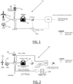
  • FIG. 1 shows a schematic illustration of an example of such hybrid system 10.
  • the technologies comprise renewable power generating units, namely a wind farm 12 and a photovoltaic plant 14.
  • the technologies also comprise an electrolyzer 16, to which the renewable power generating units 12 and 14, and optionally the grid 18, supply power.
  • the renewable power generating units 12 and 14, and optionally the grid 18, also supply power to an H 2 storage 100.
  • the renewable power generating units 12 and 14 may also supply (sell) power to the grid 18, and a curtailment may as well be implemented, as shown on FIG. 1 .
  • FIG. 1 shows a schematic illustration of an example of such hybrid system 10.
  • the technologies comprise renewable power generating units, namely a wind farm 12 and a photovoltaic plant 14.
  • the technologies also comprise an electrolyzer 16, to which the renewable power generating units 12 and 14, and optionally the grid 18, supply power.
  • the renewable power generating units 12 and 14, and optionally the grid 18, also supply power to an H 2 storage 100.
  • the electrolyzer produces H 2 , the H 2 being obtained at least in part from the power supplied by the renewable power generating units 12 and 14, this at least a part of the produced H 2 being green H 2 . At least a part of the produced H 2 is sent to storage 100, and the remaining part is delivered as outlet by the hybrid system.
  • the free variables include in these implementations the power production capacity of the wind farm 12 (X1 MW), the power production capacity of the photovoltaic plant 14 (X2 MW), the production capacity of the electrolyzer 16 (X3 MW), and the storage capacity of the storage 100 (Y1 tons).
  • RFNBO refers to the renewable fuels of non-biological origins and to the Hz produced by only renewable energies.
  • the Hz demand (“yearly or hourly objectives for H 2 production) is in the implementations illustrated by FIG. 1 a free variable.
  • the free variables of the optimization may be selected ( e . g . by a user) within these below variables, and that therefore some of the below variables may not be selected as free variables, e . g . may be fixed or may not be present at all (for example if the corresponding technology is not present).
  • the constraints of the first implementations are now presented, for examples where the system comprises the following technologies: hydrogen storage, electrolyzer, photovoltaic plant, wind farm, and a grid connection.
  • the constraints corresponding to these technology are not used in the optimization, except for the constraints related to the electrolyzer, which are mandatorily present as the aim of the algorithm is to produced green hydrogen.
  • the constraints include constraints related to the technologies of the hybrid system that are involved in the green H 2 and/or H 2 derivative production and/or conversion.
  • constraints related to the photovoltaic plant of the hybrid system which include the previously-discussed photovoltaic plant production rule.
  • this rule is implemented as follows: the power of the PV (photovoltaic) plant is calculated at each time step using the reference capacity (given by the timeseries) and the real size of the plant (which can be a variable or a parameter). In example, if the parameter "var" in optim feature is "true", the size is a variable, otherwise it is a parameter.
  • the constraints related to the photovoltaic plant further includes in implementations the total cost of the plant for the system.
  • the economic contribution for PV technology is an OPEX using a PPA price.
  • the constraints related to the technologies include constraints related to the wind farm of the hybrid system. As previously discussed, these include a wind farm production rule.
  • the power of the wind farm is calculated at each time step using the reference capacity (given by timeseries) and the real size of the plant (which can be a variable or a parameter depending on the optimization problem). If the parameter "var" in optim feature is "true”, the size is a variable, otherwise it is a parameter.
  • the constraints related to the wind farm further includes in implementations the total cost of the wind farm for the system.
  • the economic contribution for wind technology is an OPEX using a PPA price.
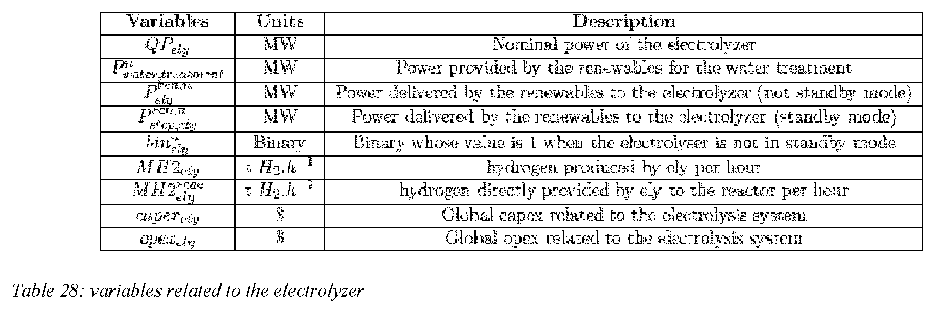
  • the electrolyzer consumes electricity during standby mode to keep the stacks hot, and this consumption is activated in the above formula using binaries.
  • the power variation rule of the electrolyzer models the maximum and minimum power variations that can be supported by the technology, and is in implementations: Power electrolyseur t ⁇ Power electrolyseur t ⁇ 1 ⁇ variation ely max ⁇ QP ely
  • the capacity rule of the electrolyzer is in implementations: load ely min . QP ely ⁇ 10 12 ⁇ 1 ⁇ bin electrolyseur t ⁇ Power electrolyseur t ⁇ QP ely . load ely max
  • the minimum and maximum load define the operating range of the electrolyzer. For the minimum load, a binary is used to bypass this constraints when the electrolyzer is turned-off.
  • the hourly grid energy purchase rule is the following inequality (hourly constraint) and defines the maximum energy that can be purchased hourly from the grid: P grid ch ⁇ P grid ch , max
  • the hourly grid energy injection rule is the following inequality (hourly constraint) and defines the maximum energy that can be sold hourly to the grid: P grid dis ⁇ P grid dis , max
  • constraints include a charge time rule of the battery, which expresses that the battery cannot be charged or discharged during the same time step, and which is given by the following inequalities: P bess dis + P bess dis , rfnbo ⁇ 10 6 ⁇ 1 ⁇ bin bess activated , pos P bess dis + P bess dis , r fnbo ⁇ time step 60 ⁇ C rate ⁇ QE bess P bess ch + P bess ch , r fnbo ⁇ 10 6 ⁇ bin bess activated , pos P bess ch + P bess ch , r fnbo ⁇ time step 60 ⁇ C rate ⁇ QE besss P bess ch + P bess ch , r fnbo ⁇ time step 60 ⁇ C rate ⁇ QE besss
  • the state-of-charge rule of the battery is now discussed.
  • the battery state of charge is an energy balance between the energy charged, discharged and the previous state of charge.
  • the charging and discharging flows are considering an efficiency which is a root square of the round trip efficiency.
  • the variables have been split to consider hydrogen produced thanks to RFNBO energy and not RFNBO.
  • RFNBO refers to H 2 produced with renewables energy.
  • the capacity rule of the battery expresses that, in the battery, only a percentage of the capacity of the battery is usable. This usable part is defined with the maximal state of charge ( soc max ) rule: Soc bess , t + Soc bess , t rfnbo ⁇ QE bess ⁇ soc max and with and the minimal state of charge ( soc min ) rule: Soc bess , t + Soc bess , t rfnbo ⁇ QE bess ⁇ soc min
  • the constraints related to H 2 storage are now discussed.
  • the charge represents the flow which goes to the Hz storage and the discharge represents the flow out of the storage, i refers to charge or discharge.
  • the H 2 storage maximal charge and discharge rule (flow constraints on MH 2 stor ch and MH 2 stor dis ) is in implementations the following: MH 2 stor , t i + MH 2 stor , t i , RFNBO ⁇ qH 2 storage max ⁇ bin _ P h 2 , stor activated , pos
  • the constraints include in implementations energy balance constraints as previously discussed. These constraints may be developed in an "energy_sys" file.
  • the constraints include in implementations mass balance constraints as previously discussed.
  • the constraints may further include in implementations further rules related to H 2 RFNBO, which are now discussed.
  • H 2 RFNBO is calculated per period (monthly or quarterly). By regulation, the H 2 RFNBO calculated is not equal to the real quantity produced. This rate is fictitious and is calculated from the total green energy available over this time horizon.
  • H 2 RFNBO The quantity of H 2 RFNBO is limited by the real delivery (outlet of the system) of Hz (RFNBO and not RFNBO) over the time horizon.
  • the new quantity of H 2 RFNBO is removed from the real non RFNBO part over this period.
  • the "new quantity" of H 2 RFNBO is added to the real RFNBO part over this period.
  • the minimal hourly demand rule and the maximal hourly demand rule are in implementations the following: MH 2 ely ds + MH 2 stor dis + MH 2 ely ds , rfnbo + MH 2 stor dis , rfnbo ⁇ hourly min prod MH 2 ely ds + MH 2 stor dis + MH 2 ely ds , rfnbo + MH 2 stor dis , rfnbo ⁇ hourly max prod
  • the variable MH 2 supply tot , n is used. This variable is calculated at the time step t using the above formulae.
  • the following fluctuation rule tags the hour when a ramp down at the outlet flow occurs.
  • the following fluctuation rule tags the hour when a ramp up at the outlet flow occurs.
  • constraints may in implementations also further comprise the following constraints.
  • the following constraint sets a minimum average rate of RFNBO to be achieved over the year. This may be used if the optimization has the objective to provide an optimal (economical) sizing that allows to produce a minimum amount of green hydrogen.
  • Green hydrogen is produced from renewable energy on site and from the grid (contribution according to the rate RFNBO).
  • ⁇ i 1 n P ely ren ⁇ ratio prod ⁇ min prod , 2 ren
  • One objective may be to have a good electrolyzer's load factor.
  • the coefficients a, b, c, d, e, f may be selected by a user (for example based on carbon emissions objectives).
  • FIG. 2 shows a schematic illustration of an example of such hybrid system 20.
  • the technologies comprise renewable power generating units, namely a wind farm 22 and a photovoltaic plant 24.
  • the technologies also comprise an electrolyzer 26, to which the renewable power generating units 22 and 24, and optionally ESS 28, supply power.
  • the renewable power generating units 22 and 24, and optionally ESS 28, also supply power to an H 2 storage 200.
  • the renewable power generating units 22 and 24 may also supply (sell) power to ESS 28, and a curtailment may as well be implemented, as shown on FIG. 2 .
  • FIG. 2 shows a schematic illustration of an example of such hybrid system 20.
  • the technologies comprise renewable power generating units, namely a wind farm 22 and a photovoltaic plant 24.
  • the technologies also comprise an electrolyzer 26, to which the renewable power generating units 22 and 24, and optionally ESS 28, supply power.
  • the renewable power generating units 22 and 24, and optionally ESS 28, also supply power to an H 2 storage 200.
  • the electrolyzer produces H 2 , the H 2 being obtained at least in part from the power supplied by the renewable power generating units 22 and 24, this at least a part of the produced H 2 being green H 2 .
  • At least a part of the produced H 2 is sent to storage 200, and the remaining part is converted, via a Haber-Bosch process, into H 2 derivative (the derivative illustrated on the figure is NH 3 , but it is to be understood that any alternative or additional derivative may be contemplated).
  • H 2 derivative the derivative illustrated on the figure is NH 3 , but it is to be understood that any alternative or additional derivative may be contemplated.
  • the free variables include in these implementations the power production capacity of the wind farm 22 (X1 MW), the power production capacity of the photovoltaic plant 24 (X2 MW), the production capacity of the electrolyzer 26 (X3 MW), the storage capacity of the storage 200 (Y1 tons), the capacity of the battery (X4 MW), the production capacity of the Haber-Bosch process (Y2 million tons per annum (“MTPA”)).
  • the constraints may be formulated based on values of the parameters that include an efficiency of the electrolyzer, an efficiency of the sea water treatment unit, and consumption of the storage, a pressure of the H 2 storage, a power consumed for H 2 derivative synthesis, and a production ratio between the amount of derivatives produced and the amount of H 2 used for this production.
  • RFNBO refers to the renewable fuels of non-biological origins and to the H 2 produced by only renewable energies.
  • the free variables of the optimization may be selected ( e.g . by a user) within these below variables, and that therefore some of the below variables may not be selected as free variables, e.g . may be fixed or may not be present at all (for example if the corresponding technology is not present).
  • constraints of the second implementations are now presented.
  • the constraints corresponding to these technology are not used in the optimization, except for the constraints related to the electrolyzer, which are mandatorily present.
  • the constraints related to a H 2 derivative demand over a predetermined time period are identical to those related to a H 2 demand discussed in the first implementations, except that H 2 derivative(s) is/are demanded instead of H 2 .
  • the constraints related to the wind farm may further include a cost of the wind farm.
  • the wind cost considers the CAPEX and OPEX per year using a parameter proportional to the installed capacity.
  • Opex wind QP wind ⁇ cost Opex wind ⁇ 10 3
  • the constraints related to the wind farm may further include a cost of the PV plant.
  • the PV cost considers the CAPEX and OPEX per year using a parameter proportional to the installed capacity.
  • Opex pv QP pv ⁇ cost Opex pv ⁇ 10 3
  • the PGU activation rule is the following (Power of renewables lower to the size of the PGU: the PGU is activated only when the renewables energy available is lower than the power of the PGU, for example sized according to the turndown of the process): P pgu n ⁇ p PGU max ⁇ 1 ⁇ bin PGU n ⁇ 10 9 ⁇ P wind n + P pv n ⁇ p PGU max
  • the power variation rule of the electrolyzer is the following: P ely ren , t ⁇ P ely ren , t ⁇ 1 ⁇ variation ely max
  • the capacity rule of the electrolyzer is the following (the electrolyzer unit is operating between a minimum and maximum load): load ely min . QP ely ⁇ 10 12 ⁇ 1 ⁇ bin ely n ⁇ P ely ren , n + P ely grid , n ⁇ QP ely . load ely max
  • the water treatment rule may also be part of the constraints in the first implementations previously discussed.
  • the constraints may further include a cost of the electrolyzer.
  • the electrolyzer cost considers the CAPEX and OPEX per year using a parameter proportional to the installed capacity.
  • Opex ely QP ely ⁇ cost Opex ely ⁇ 10 3
  • the charge time rule for a battery of the system is the following (The battery cannot be charged or discharged during the same time step.): P bess dis ⁇ 10 6 ⁇ 1 ⁇ bin bess activated , pos P bess dis ⁇ time step 60 ⁇ C rate ⁇ QE bess
  • the battery state of charge is an energy balance between the energy charged, discharged and the previous state of charge. The charging and discharging flows are considering an efficiency which is a root square of the round trip efficiency.
  • Soc bess , t end
  • the capacity rule of the battery is the following (In the battery, only a percentage of the capacity is usable. This usable part is defined with the soc min and soc min : Soc bess , t ⁇ QE bess ⁇ soc max Soc bess , t ⁇ QE bess ⁇ soc min
  • the constraints related to the battery may further include a battery cost.
  • the Hz storage maximal charge and discharge rule is in implementations the following (flows-constraints on MH 2 stor ch and MH 2 stor dis : MH 2 stor , t ch ⁇ 10 4 ⁇ bin ch pos MH 2 stor , t dis ⁇ 10 4 ⁇ 1 ⁇ bin ch pos
  • the flow of charge and discharge can be limited to a maximum value (tons/hours) by adding the following to the rule MH 2 stor , t ch ⁇ qH 2 ch max MH 2 stor , t dis ⁇ qH 2 dis max
  • an efficiency curve can be used if the size of the plant is fixed and a multiple of 0.8 MTPA (KBR curve).
  • KBR curve 0.8 MTPA
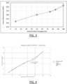
  • FIG. 3 shows an example of a curve of the power required (in MW) as a function of the throughput in Ammonia (in percentage).
  • FIG. 4 shows an example of the efficiency curve for the production of Ammonia, representing the power required for production (in MW) as a function of the load factor of the NH 3 unit (in percentage).
  • the efficiency curve is represented on FIG. 4 ("Efficiency MW" caption), as well as its linearization (dotted curve, "linear (Efficiency MW)” caption).
  • the reactor capacity is defined in MTPA (millions metric tons per year). This value is calculated as the maximum flow of H 2 (tons/h) times 8760.
  • the constraints related to the reactor may further include in implementations an energy vector cost for the reactor.
  • the one or more reactor operation rules consists in implementations in the following several operation rules.
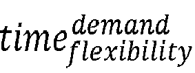
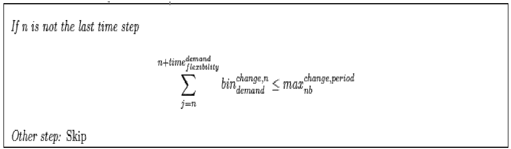
  • This constraint is related to process limitations(warm start). If the reactor stops it will takes at least reac downtime hours to restart.
  • the second operation rule is the following: M reac , n ⁇ bin n , reac ⁇ 10 6 This constraint is used to define 0 production when the reactor is under the turndown value.
  • the third operation rule is the following: M reac , n ⁇ 8760 ⁇ 60 ⁇ QM reac ⁇ time step ⁇ reac min , prod ⁇ 10 12 ⁇ 1 ⁇ bin reac
  • This constraint frames the production of the reactor at a production higher than the turndown.
  • the second part of the inequality is used to bypass this constraint when the reactor is turned off.
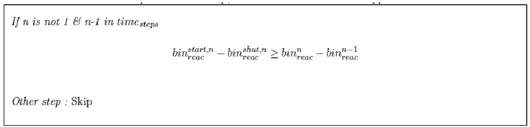
  • the fifth operation rule is the following: If n is not 1 & n ⁇ 1 in time step bin reac start , n ⁇ bin reac shut , n ⁇ bin reac n ⁇ bin reac n ⁇ 1 Other step : Skip This constraint and the next one are used to tag a change in the status of the reactor. If the status of the reactor is not the as the previous time step, then the reactor has been stopped or started.
  • the sixth operation rule is the following: bin reac start , n + bin reac shut , n ⁇ 1 This constraint is similar to the previous one and may not be used.
  • the eighth operation rule is the following (The operation of the reactor is limited for ramp-up proportionally to the installed capacity.): If n is different from 1 M reac n ⁇ M reac n ⁇ 1 ⁇ QM reac ⁇ reac , max rampup Other step : Skip
  • the ninth operation rule is the following (The operation of the reactor is limited for ramp-down proportionally to the installed capacity.): If n is different from 1 M reac n ⁇ M reac n ⁇ 1 ⁇ QM reac ⁇ reac , max rampdown ⁇ 10 12 ⁇ 1 ⁇ bin reac n Other step : Skip
  • the grid is used to provide electricity for the all system.
  • the method is computer-implemented. This means that steps (or substantially all the steps) of the method are executed by at least one computer, or any system alike. Thus, steps of the method are performed by the computer, possibly fully automatically, or, semi-automatically. In examples, the triggering of at least some of the steps of the method may be performed through user-computer interaction.
  • the level of user-computer interaction required may depend on the level of automatism foreseen and put in balance with the need to implement user's wishes. In examples, this level may be user-defined and/or pre-defined.
  • a typical example of computer-implementation of a method is to perform the method with a system adapted for this purpose.
  • the system may comprise a processor coupled to a memory and a graphical user interface (GUI), the memory having recorded thereon a computer program comprising instructions for performing the method.
  • GUI graphical user interface
  • the memory may also store a database.
  • the memory is any hardware adapted for such storage, possibly comprising several physical distinct parts (e.g. one for the program, and possibly one for the database).
  • FIG. 5 shows an example of the system, wherein the system is a client computer system, e.g. a workstation of a user.
  • the system is a client computer system, e.g. a workstation of a user.
  • the client computer of the example comprises a central processing unit (CPU) 1010 connected to an internal communication BUS 1000, a random access memory (RAM) 1070 also connected to the BUS.
  • the client computer is further provided with a graphical processing unit (GPU) 1110 which is associated with a video random access memory 1100 connected to the BUS.
  • Video RAM 1100 is also known in the art as frame buffer.
  • a mass storage device controller 1020 manages accesses to a mass memory device, such as hard drive 1030.
  • Mass memory devices suitable for tangibly embodying computer program instructions and data include all forms of nonvolatile memory, including by way of example semiconductor memory devices, such as EPROM, EEPROM, and flash memory devices; magnetic disks such as internal hard disks and removable disks; magneto-optical disks.
  • a network adapter 1050 manages accesses to a network 1060.
  • the client computer may also include a haptic device 1090 such as cursor control device, a keyboard or the like.
  • a cursor control device is used in the client computer to permit the user to selectively position a cursor at any desired location on display 1080.
  • the cursor control device allows the user to select various commands, and input control signals.
  • the cursor control device includes a number of signal generation devices for input control signals to system.
  • a cursor control device may be a mouse, the button of the mouse being used to generate the signals.
  • the client computer system may comprise a sensitive pad, and/or a sensitive screen.
  • the computer program may comprise instructions executable by a computer, the instructions comprising means for causing the above system to perform the method.
  • the program may be recordable on any data storage medium, including the memory of the system.
  • the program may for example be implemented in digital electronic circuitry, or in computer hardware, firmware, software, or in combinations of them.
  • the program may be implemented as an apparatus, for example a product tangibly embodied in a machine-readable storage device for execution by a programmable processor. Method steps may be performed by a programmable processor executing a program of instructions to perform functions of the method by operating on input data and generating output.
  • the processor may thus be programmable and coupled to receive data and instructions from, and to transmit data and instructions to, a data storage system, at least one input device, and at least one output device.
  • the application program may be implemented in a high-level procedural or object-oriented programming language, or in assembly or machine language if desired. In any case, the language may be a compiled or interpreted language.
  • the program may be a full installation program or an update program. Application of the program on the system results in any case in instructions for performing the method.
  • the computer program may alternatively be stored and executed on a server of a cloud computing environment, the server being in communication across a network with one or more clients. In such a case a processing unit executes the instructions comprised by the program, thereby causing the method to be performed on the cloud computing environment.
Landscapes

  • Engineering & Computer Science (AREA)
  • Business, Economics & Management (AREA)
  • Human Resources & Organizations (AREA)
  • Economics (AREA)
  • Strategic Management (AREA)
  • Marketing (AREA)
  • Game Theory and Decision Science (AREA)
  • Entrepreneurship & Innovation (AREA)
  • Development Economics (AREA)
  • Operations Research (AREA)
  • Quality & Reliability (AREA)
  • Tourism & Hospitality (AREA)
  • Physics & Mathematics (AREA)
  • General Business, Economics & Management (AREA)
  • General Physics & Mathematics (AREA)
  • Theoretical Computer Science (AREA)
  • Supply And Distribution Of Alternating Current (AREA)

Abstract

The disclosure relates to method for optimizing a hybrid system for green H2 and/or H2 derivative production and/or conversion. The method comprises providing constraints, which include one or more constraints each related to a H2 demand over a predetermined time period, and/or one or more constraints related to technologies of the hybrid system that are involved in the green H2 and/or H2 derivative production and/or conversion. The method comprises providing an objective function quantifying a rate of the green H2 and/or H2 derivative production and/or conversion by only renewable technologies of the system. The method comprises optimizing the objective function based on the constraints, the optimization using a MILP optimization method based on a linear formulation of the constraints and having free variables including a green H2 and/or H2 derivative production capacity of an electrolyzer of the system and operational variables for mass and power exchanges between the system technologies.

Description

    TECHNICAL FIELD
  • The disclosure relates to the field of computer programs and systems, and more specifically to a method, system and program for optimizing a hybrid system for green H2 and/or H2 derivative production and/or conversion.
  • BACKGROUND
  • Green H2 and/or green H2 derivatives are more and more used nowadays, and the demand for green H2 and/or green H2 derivatives increases.
  • Within this context, there is still a need for improved solutions for optimizing a hybrid system for green H2 and/or H2 derivative production and/or conversion.
  • SUMMARY
  • It is therefore provided a computer-implemented method for optimizing a hybrid system for green H2 and/or H2 derivative production and/or conversion. The method comprises providing constraints. The constraints include one or more constraints each related to a H2 and/or H2 derivative demand over a predetermined time period, and/or one or more constraints related to technologies of the hybrid system that are involved in the green H2 and/or H2 derivative production and/or conversion. The method further comprises providing an objective function. The objective function quantifies a rate of the green H2 and/or H2 derivative production and/or conversion by only renewable technologies of the hybrid system. The method further comprises optimizing the objective function based on the constraints. The optimization has free variables. The free variables include a green H2 and/or H2 derivative production capacity of an electrolyzer of the system and operational variables for mass and power exchanges between the technologies of the system. The free variables also include a renewable power production capacity of the hybrid system. The optimization uses a MILP optimization method that is based on a linear formulation of the constraints.
  • The method may comprise one or more of the following:
    • the free variables further include variables that represent a BESS and/or H2 storage capacity, and/or variables that represent a capacity of a conversion system for production of H2 derivatives;
    • the constraints include non-linear constraints, and the method further comprises, before the optimization:
      • ∘ linearizing the non-linear constraints;
    • the one or more constraints each related to a H2 and/or H2 derivative demand over a predetermined time period include one or more of:
      • ∘ an hourly H2 and/or H2 derivative demand rule;
      • ∘ a daily H2 and/or H2 derivative demand rule; and/or
      • ∘ an annual H2 and/or H2 derivative demand rule;
    • the hourly H2 and/or H2 derivative demand rule includes:
      • ∘ a minimal hourly demand rule and/or a maximal hourly demand rule; and/or
      • ∘ a minimal ramp-up rule and/or a maximal ramp-down rule;
    • the daily H2 and/or H2 derivative demand rule includes a minimal daily demand rule and/or a maximal daily demand rule;
    • the one or more constraints each related to a H2 and/or H2 derivative demand over a predetermined time period further include one or more fluctuation rules over the predetermined time period;
    • the one or more constraints related to technologies of the hybrid system that are involved in the green H2 and/or H2 derivative production and/or conversion include one or more of:
      • ∘ a photovoltaic plant production rule;
      • ∘ a wind farm production rule;
      • ∘ one or more constraints related to an electrolyzer of the system, including a power consummation rule during production and/or conversion when the electrolyzer is turned off, a power variation rule of the electrolyzer, a water treatment consumption rule, and/or a capacity rule of the electrolyzer;
      • ∘ a charge time rule for a battery of the system, a state-of-charge rule of the battery, a state-of-charge end rule of the battery, and/or a capacity rule of the battery;
      • ∘ an hourly grid energy purchase and/or injection rule and/or an annual maximal grid energy purchase rule; and/or
      • ∘ a H2 storage maximal charge and discharge rule, a H2 state-of-charge rule, and/or an electricity consumption for Hz storage rule;
    • the green H2 and/or H2 derivative production and/or conversion consists in at least H2 derivative production, and the one or more constraints related to technologies of the hybrid system further include:
      • ∘ a PGU power production rule and/or a PGU activation rule;
    • the green H2 and/or H2 derivative production and/or conversion consists at least in H2 derivative production, and the constraints include one or more of:
      • ∘ a H2 derivative production rule;
      • ∘ a power consumption rule for H2 derivative production;
      • ∘ a reactor capacity rule; and/or
      • ∘ one or more reactor operation rules;
    • the constraints include energy balance constraints and/or mass balance constraints;
    • the green H2 and/or H2 derivative production and/or conversion consists in at least green H2 production, and:
      • o the energy balance constraints include:
        • ▪ an energy balance equation for renewable energy;
        • ▪ a grid energy balance equation;
        • ▪ a battery state of charge equation; and
        • ▪ an electrolyzer stand-by-mode consumption rule; and/or
      • o the mass balance constraints include:
        • ▪ a green and non-green H2 production distinction rule;
        • ▪ a balance rule for Hz storage; and
        • ▪ a balance rule for H2 directly delivered and Hz stored; and/or
    • the green H2 and/or H2 derivative production and/or conversion consists in at least H2 derivative production, and:
      • o the energy balance constraints include:
        • ▪ an energy balance equation for renewable energy;
        • ▪ a battery state of charge equation; and
        • ▪ a grid energy balance equation; and/or
      • o the mass balance constraints include:
        • ▪ a H2 production rule;
        • ▪ a water treatment rule;
        • ▪ a balance rule for Hz storage;
        • ▪ a balance rule for H2 derivative production; and
        • ▪ a balance rule for H2 directly consumed by conversion reactor and H2 stored.
  • It is further provided a computer program comprising instructions for performing the method.
  • It is further provided a computer readable storage medium having recorded thereon the computer program.
  • It is further provided a computer system comprising a processor coupled to a memory, the memory having recorded thereon the computer program.
  • BRIEF DESCRIPTION OF THE DRAWINGS
  • Non-limiting examples will now be described in reference to the accompanying drawings, where:
    • FIG.s 1 to 4 illustrate the method; and
    • FIG. 5 shows an example of the system.
    DETAILED DESCRIPTION
  • It is proposed a computer-implemented method for optimizing a hybrid system for green H2 and/or H2 derivative production and/or conversion. The method comprises providing constraints. The constraints include one or more constraints each related to a Hz demand over a predetermined time period, and/or one or more constraints related to technologies of the hybrid system that are involved in the green H2 and/or H2 derivative production and/or conversion. The method further comprises providing an objective function. The objective function quantifies a rate of the green H2 and/or H2 derivative production and/or conversion by only renewable technologies of the hybrid system. The method further comprises optimizing the objective function based on the constraints. The optimization has free variables. The free variables include a green H2 and/or H2 derivative production capacity of an electrolyzer of the system and operational variables for mass and power exchanges between the technologies of the system. The free variables also include a renewable power production capacity of the hybrid system. The optimization uses a MILP optimization method that is based on a linear formulation of the constraints.
  • The method (i.e. the proposed method for optimizing a hybrid system for green H2 and/or H2 derivative production and/or conversion) constitutes an improved solution for optimizing a hybrid system for green H2 and/or H2 derivative production and/or conversion.
  • Notably, the method optimizes a hybrid system that produces green Hz and/or that produces green H2 derivative (through conversion of green H2 into green H2 derivative) by optimizing an objective function that quantifies a rate of the green H2 and/or H2 derivative production and/or conversion by only renewable technologies of the hybrid system. This means that the method optimizes the rate of production of green H2 and/or H2 derivative using only renewable technologies, i.e. while the system may comprise other sources of energy than renewable technologies (e.g. the grid), the method optimizes the rate of the production green H2 and/or H2 derivative by only the renewable part of the energy sources. The method thus provides an optimal setting and sizing of the system (in terms of operational variables and in term of capacity of the involved technologies, including the electrolyzer) with respect to production rate of the green H2 and/or H2 derivative by green technologies only. This allows to reduce the carbon footprint of the hybrid system.
  • Furthermore, the method performs the optimization without requiring any predefined dispatch rule of any predefined choice of the technologies of the hybrid system. This provides flexibility in the technologies that may be part of the hybrid system and in the energy dispatch within the system. For example, a user of the method may optimize the system for any dispatch configuration and/or any choice of technologies he/she wants, without being constrained by a predefined setting of technologies or by a predefined energy dispatch rule. The user may for example add or remove technologies in an existing system (for example adding batteries or Hz storage systems, or considering only certain types of production units) and optimize the system for these various configurations. The method also allows to account for operational constraints at both the technologies level and the system level (e.g. production quantity, RFNBO rate (as discussed hereinafter)).
  • Moreover, the method performs the optimization using a MILP optimization method. The MILP optimization allows accounting for all the constraints related to the system in the optimization and thus to provide for a global optimization of the system.
  • The method is for optimizing a hybrid system for green H2 and/or H2 derivative production and/or conversion. By "optimizing the hybrid system", it is meant that the method provides an optimize setting and/or sizing of the hybrid system with respect to production of green H2 and/or of H2 derivative (through the conversion of green H2). In the case of the method, it is the rate of production of green Hz and/or of Hz derivative that is optimized with respect to the constraints and by varying the free variables, which include a renewable power production capacity of the hybrid system, a green H2 and/or H2 derivative production capacity of an electrolyzer of the system and operational variables for mass and power exchanges between the technologies of the system. In other words, the method determines a value for the free variables to that the system is optimized for green H2 and/or H2 derivative production in that the rate of production of green H2 and/or of H2 derivative tends to reach its optimal value for this determined value of the free variables.
  • The system is a hybrid system for green H2 and/or H2 derivative production and/or conversion. In other words, the system is hybrid system (e.g. a hybrid power and/or heat plant) that produces green H2 and/or that produces H2 derivative by converting green H2 into H2 derivative. As known per se, Hz designates the dihydrogen. By H2 derivative production, it is meant the production of one or more H2 derivatives, such as one or more of NH3 (ammonia), MeOH (Methanol), and/or LH2 (liquid hydrogen). Thus, by "green H2 and/or H2 derivative production and/or conversion", it is meant the production of green H2 and/or the production of one or more green H2 derivatives through conversion of green Hz into these of one or more green H2 derivatives.
  • The system being hybrid, it comprises green (renewable) technologies and non-green technologies. The hybrid system comprises an electrolyzer, that produces H2 as known per se. The hybrid system may comprise renewable power generating units, including a wind farm and/or a photovoltaic plant, that supply electrical power to the electrolyzer (the electrolyzer using this power to produce H2, this produced H2 being referred to as "green H2"), and that may supply power to other technologies (e.g. a H2 storage). The hybrid system may be connected to the grid, that may supply power (i.e. non-green power) to the technologies of the system. The H2 produced from power that is not supplied by the renewable units is referred to as non-green Hz. Because of the connection between the grid and the system, the grid may be referred to, for the sake of efficiency, as being a technology of the system, although the grid is not per se a part of the system but rather connected thereto. The hybrid system may further comprise a H2 storage. The hybrid system may further comprise a reactor, that converts H2 into H2 derivative(s). H2 derivative(s) converted from green H2 is/are referred to as green H2 derivative(s). The system may further comprise a battery (or several batteries, but only one battery is discussed in the following, for the sake of efficiency) for storing excesses of electrical power and/or supplying electrical power when needed. The system may further comprise a PGU (power generating unit, for example a gas turbine), or several PGU, but only one PGU is discussed in the following, for the sake of efficiency. The PGU supplies non-green power.
  • The method may comprise selecting the technologies of the system prior to the optimization, i.e. selecting the technologies to be accounted for in the optimization. This selection may be performed by the user and allows to test and optimize various configurations of the system.
  • The method comprises providing inputs to the optimization. The inputs include the constraints and the objective function. The constraints are constraints to the optimization, i.e. the optimization modifies the value of the free variables so as to reach, or at least tend to reach, an optimal value of the objective function, but while respecting the constraints. The objective function is the function to be optimized by the optimization, i.e. the optimization modifies the values of the free variables so that the function reaches, or at least tends to reach, its optimal value, for example by becoming sufficiently close to the optimal value with respect to a convergence criterion.
  • The constraints include one or more constraints each related to a H2 and/or H2 derivative demand over a predetermined time period, i.e. one or more constraints each constraining the system (i.e. while optimize) in terms of meeting a given H2 (if the system is for Hz production) and/or H2 derivative (if the system is for H2 derivative production) demand requirement over the predetermined time period. The one or more constraints each related to a H2 demand over a predetermined time period may include one or more of:
    • an hourly H2 and/or H2 derivative demand rule, i.e. a rule that requires the system to meet hourly a given production of H2 and/or H2 derivative;
    • a daily H2 and/or H2 derivative demand rule, i.e. a rule that requires the system to meet daily a given production of H2 and/or H2 derivative; and/or
    • an annual H2 and/or H2 derivative demand rule, i.e. a rule that requires the system to meet annually a given production of H2 and/or H2 derivative.
  • The annual H2 and/or H2 derivative demand rule may be an equation that forces the total downstream H2 and/or H2 derivative delivery over a year to be equal to a given demand value (e.g. provided by a user at the providing of the constraints).
  • The hourly H2 and/or H2 derivative demand rule may include a minimal hourly demand rule and/or a maximal hourly demand rule, for example consisting in an inequation that forces the hourly downstream H2 and/or H2 derivative delivery to be larger than a given minimal demand value (e.g. provided by a user at the providing of the constraints) and/or an inequation that forces the hourly downstream H2 and/or H2 derivative delivery to be smaller than a given maximal demand value (e.g. provided by a user at the providing of the constraints). The hourly H2 and/or H2 derivative demand rule may additionally or alternatively include a minimal ramp-up rule and/or a maximal ramp-down rule. This may consist in an inequation that forces the downstream H2 and/or H2 derivative delivery at each time step to be larger than a given minimal ramp value (e.g. provided by a user at the providing of the constraints) and/or an inequation that forces the downstream H2 and/or H2 derivative delivery at each time step to be smaller than a given maximal ramp value (e.g. provided by a user at the providing of the constraints).
  • The daily H2 and/or H2 derivative demand rule may include a minimal daily demand rule and/or a maximal daily demand rule, for example consisting in an inequation equation that forces the daily downstream H2 and/or H2 derivative delivery to be larger than a given minimal demand value (e.g. provided by a user at the providing of the constraints) and/or an inequation that forces the daily downstream H2 and/or H2 derivative delivery to be smaller than a given maximal demand value (e.g. provided by a user at the providing of the constraints).
  • The one or more constraints each related to a H2 and/or H2 derivative demand over a predetermined time period may further include one or more fluctuation rules over the predetermined time period. These one or more rules may comprise or consist in one or more of the following rules:
    • a rule limiting the number of changes of the downstream flow(s) of H2 and/or H2 derivative, for example in the form of an inequation forcing this number of changes to be lower than a predefined maximal value (which for example may be provided by a user at the providing of the constraints);
    • a rule tagging an hour when a ramp down at the downstream flow(s) occurs; and/or
    • a rule tagging an hour when a ramp up at the downstream flow(s) occurs.
  • Additionally or alternatively, the constraints include one or more constraints related to technologies of the hybrid system that are involved in the green H2 and/or H2 derivative production and/or conversion. These one or more constraints may comprise any constraint or set of constraints regarding the functioning of these technologies, such as one or any combination of production rules, power consumption rules, charge time rules, power variation rules, capacity rules, storage rules, charge and discharge rules, and/or operation rules.
  • The constraints thus include the one or more constraints related the H2 and/or H2 derivative demand over a predetermined time period, or the one or more constraints related to technologies of the hybrid system that are involved in the green H2 and/or H2 derivative production and/or conversion, or both of these constraints. For example, the one or more constraints related the H2 and/or H2 derivative demand over a predetermined time period may be part of the constraints and are thus constraint to enforce in the optimization, and not variables to be modified during the optimization. In this case, the optimization may for example optimize the sizing of the renewable part of the system for meeting this demand constraint. Alternatively, this sizing may be a constraint to enforce during the optimization, and the H2 and/or H2 derivative demand may be a free variable to optimize for this fixed sizing. Yet alternatively, both this sizing and this demand may be constraints.
  • The one or more constraints related to technologies of the hybrid system that are involved in the green H2 and/or H2 derivative production and/or conversion may include one or more of:
    • a photovoltaic plant production rule, i.e. a rule that defines the power production by the photovoltaic plant, e.g. in the form of a formula yielding the power produced by the photovoltaic at each time step;
    • a wind farm production rule, i.e. a rule that defines the power production by the wind farm, e.g. in the form of a formula yielding the power produced by the wind farm at each time step;
    • one or more constraints related to an electrolyzer of the system, including a power consummation rule during production and/or conversion when the electrolyzer is turned off (i.e. a rule, for example in the form of a formula or a set of formulas, defining the power consumed by the electrolyzer to keep the stacks hot, during production of green Hz for sole H2 production and/or for downstream Hz conversion into H2 derivatives, when the electrolyzer is turned off/in standby mode), a power variation rule of the electrolyzer (i.e. a rule, for example in the form of an inequation, defining the maximum and minimum power variations that the electrolyzer can accept), a water treatment consumption rule (i.e. a rule, for example in the form of a formula, defining the power used for water treatment, as the electrolyzer may need high purity water to produce H2), and/or a capacity rule of the electrolyzer (i.e. a rule, for example in the form of one or more inequations, defining the operating range of the electrolyzer);
    • a charge time rule for a battery of the system (i.e. a rule defining the moments of charge and of discharge of the battery, as the battery cannot be charged or discharged during the same time step), a state-of-charge rule of the battery (e.g. a rule defining, for example in the form of an equation, an energy balance between the energy charged, discharged, and the previous state of charge), a state-of-charge end rule of the battery (e.g. a rule forcing the state of charge at the end of the year to be equal to the state of charge at the first time step), and/or a capacity rule of the battery (e.g. a rule defining, for example in the form of one or more inequalities, a usable percentage of the battery capacity);
    • an hourly grid energy purchase and/or injection rule, and/or an annual maximal grid energy purchase rule. The hourly grid energy purchase and/or injection rule may include or consist in a rule defining a maximum energy that can be purchased hourly from the grid and/or a rule defining a maximum energy that can be sold hourly to the grid, and/or a rule preventing to buy and sell energy on the grid at the same time step. The rule defining the maximum energy that can be purchased hourly from the grid may for example be an inequation forcing the energy purchased hourly from the grid to be lower than a predefined maximal value (which may be provided by a user at the providing of the constraints) and/or the rule defining the maximum energy that can be sold hourly from the grid may for example be an inequation forcing the energy sold hourly from the grid to be lower than a predefined maximal value (which may be provided by a user at the providing of the constraints). The annual maximal grid energy purchase rule may be rule defining a maximum energy that can be purchased from the grid per year (e.g. in the form of an inequation constraining the energy purchased from the grid over a year to be lower than a maximal value, which for example can be provided by a user at the providing of the constraints); and/or
    • a H2 storage maximal charge and discharge rule (i.e. a rule enforcing a maximal charge and discharge for the H2 storage, for example as flow constraints), a Hz state-of-charge rule (e.g. a rule, for example a set of equations, describing a balance between the charge, the discharge, and the previous state of charge), and/or an electricity consumption for H2 storage rule (for example in the form of a formula yielding the electricity consumed for storage depending of the amount of Hz stored).
  • It is to be understood that for each one of the above rule, the rule may be comprised in the constraints only when the corresponding technology, that is the technology concerned by the rule, is comprised by the hybrid system.
  • The green H2 and/or H2 derivative production and/or conversion may consist in at least H2 derivative production (that is, the hybrid system delivers at least green H2 derivative, but may in addition deliver green H2). In this case, the one or more constraints related to technologies of the hybrid system may further include a PGU power production rule and/or a PGU activation rule. Thus, the hybrid system technologies comprise in such a case a PGU (power generating unit). The PGU power production rule may be a rule defining, for example in the form of an equation or formula, the power produced by the PGU using Hz from storage. The PGU activation rule may be a rule, such as an inequation, enforcing activation of the PGU only when the renewable energy available is lower than the power of the PGU.
  • Still in the case where the green H2 and/or H2 derivative production and/or conversion consists at least in H2 derivative production, the constraints may further include one or more of:
    • a H2 derivative production rule, for example a rule for enforcing a given H2 derivative production, for example based on an imposed constant conversion ratio between H2 derivative and H2;
    • a power consumption rule for H2 derivative production, such as one or more formulas yielding the value of power consumption for H2 derivative production, for example including one or more formulas based on an efficiency curve and/or one or more formulas using a constant efficiency proportional to H2 consumption;
    • a reactor capacity rule, for example in the form of formulas yielding the maximum flow of H2 for the reactor; and/or
    • one or more reactor operation rules, that is rules each enforcing respect of a given specification or setting of the reactor.
  • The constraints may further include energy balance constraints and/or mass balance constraints, such as one or more equations describing energy balance and/or one or more equations describing mass balance.
  • The green H2 and/or H2 derivative production and/or conversion may consists in at least green Hz production (that is, the system produces green Hz and may optionally produce in addition derivatives thereof).
  • In this case, the energy balance constraints may include:
    • an energy balance equation for renewable energy, i.e. an equation that describes energy balance for the renewable part of the hybrid system;
    • a grid energy balance equation, i.e. an equation that describes energy balance for the grid part of the hybrid system;
    • a battery state of charge equation (which may be the battery state of charge rule previously discussed), such as a rule defining, for example in the form of an equation, an energy balance between the energy charged, discharged, and the previous state of charge; and
    • an electrolyzer stand-by-mode consumption rule, i.e. a rule, such as an equation, describing the consumption of the electrolyzer in stand-by mode.
  • Still in this case, additionally or alternatively, the mass balance constraints may include:
    • a green and non-green H2 production distinction rule, for example consisting in an equation describing the mass of green H2 produced and an equation describing the mass of non-green Hz produced;
    • a balance rule for H2 storage (for example, the previously-discussed balance rule between the charge, the discharge, and the previous state of charge); and
    • a balance rule for H2 directly delivered and H2 stored, such as one or more equations describing a balance between H2 that is directly delivered and H2 that is stored.
  • As previously discussed, the green H2 and/or H2 derivative production and/or conversion may consist in at least H2 derivative production
  • In such a case, the energy balance constraints may include:
    • an energy balance equation for renewable energy, i.e. an equation that describes energy balance for the renewable part of the hybrid system;
    • a battery state of charge equation (which may be the battery state of charge rule previously discussed), such as a rule defining, for example in the form of an equation, an energy balance between the energy charged, discharged, and the previous state of charge; and
    • a grid energy balance equation i.e. an equation that describes energy balance for the grid part of the hybrid system.
  • Still in this case, additionally or alternatively, the mass balance constraints may include:
    • a H2 production rule, for example in the form of a formula yielding the mass of H2 produced;
    • a water treatment rule, for example in the form an balance equation linking the power used for water treatment, the H2 produced, and the;
    • a balance rule for H2 storage (for example, the previously-discussed balance rule between the charge, the discharge, and the previous state of charge);
    • a balance rule for H2 derivative production; and
    • a balance rule for H2 directly consumed by conversion reactor and stored, such as one or more equations describing a balance between H2 that is consumed by the conversion reactor and H2 that is stored.
  • The constraints may be provided by a user. For example, the user may select constraints within a predefined list of constraints, defining the constraints himself/herself, and/or providing predetermined values/numbers/constants involved in the constraints (for example by selecting these values). Alternatively, at least some constraints may be predefined (i.e. provided by the system executing the method) and the other constraints may be provided by the user.
  • The inputs further comprise an objective function. The objective function may be predefined and thus provided by the computer system. The objective function is a function that quantifies a rate of the green H2 and/or H2 derivative production and/or conversion by only renewable technologies of the hybrid system. In other words, the function quantifies the rate of production of the green H2 and/or the derivatives thereof by the renewable technologies of the system and no other technologies. The objective function depends on the free variables of the optimization, for example directly, or for example indirectly (i.e. the objective function depends on intermediate variables or terms that themselves depend on the free variables).
  • The free variables include a green H2 and/or H2 derivative production capacity of an electrolyzer of the hybrid system and operational variables for mass and power exchanges between the technologies of the hybrid system. The green H2 and/or H2 derivative production capacity of an electrolyzer of the hybrid system is the capacity of the electrolyzer to produce H2 to be delivered by the hybrid system and/or H2 to be transformed into H2 derivatives then delivered by the hybrid system. The operational variables for mass and power exchanges between the technologies of the hybrid system are variables representing (e.g. all the) flows of power and/or of matter within the hybrid system. These variables may comprise or consist in all the variables that depend on the time. The free variables further include a renewable power production capacity of the hybrid system, for example in the form of variables representing a capacity of the renewable technologies (e.g. a power production capacity). The free variables may further include the variables that represent a BESS and/or H2 storage capacity, and/or variables that represent a capacity of a conversion system for production of H2 derivatives.
  • The method further comprises optimizing the objective function based on the constraints, said free variables being the free variables of the optimization. This means that the method searches for values of the free variables for which the constraints are respected and the value of the objective function is optimal or tends to be optimal (e.g. with respect to a convergence criterion). This optimization is performed using a MILP (Mixed-Integer Linear Programming) optimization method. Any MILP may be used. The concept of MILP optimization is well known and need not being further discussed. The MILP optimization is based on a linear formulation of the constraints. This means that the MILP optimization accounts for the constraints but formulated linearly. The constraints which are already linear when provided (which in examples may be all of the constraints) (i.e. are provided already with a linear formulation) are directly used in the optimization. The constraints may also include (or consist in) non-linear constraints, and in this case the method further comprises, before the optimization, linearizing the non-linear constraints. Linearizing a constraint means determining or providing a linear expression of the constraint and/or of a parameter therein. For example, for the constraints using specifications curves of technologies of the hybrid system (e.g. efficiency curves as discussed hereinbelow), linearizing may comprise performing a linearization by parts of these curves.
  • Implementations of the method are now discussed. These implementations notably discuss mathematical formulations of the constraints, variables, and of the objective function. It is to be understood that these mathematical formulations may be used for any of the constraints, variables and objective function already described hereinabove, or any combination thereof, independently of the other/remaining mathematical formulations discussed in the implementations.
  • It is first discussed implementations where the hybrid system is for green H2 production. The first-discussed implementations (also referred to as "first implementations hereinbelow) concern the optimization of the system in the case where the percentage of green H2 has to reach a minimum value over one year. Optionally, the optimization may include maximizing the net revenues.
  • FIG. 1 shows a schematic illustration of an example of such hybrid system 10. As illustrated on FIG. 1, the technologies comprise renewable power generating units, namely a wind farm 12 and a photovoltaic plant 14. The technologies also comprise an electrolyzer 16, to which the renewable power generating units 12 and 14, and optionally the grid 18, supply power. The renewable power generating units 12 and 14, and optionally the grid 18, also supply power to an H2 storage 100. The renewable power generating units 12 and 14 may also supply (sell) power to the grid 18, and a curtailment may as well be implemented, as shown on FIG. 1. As illustrated on FIG. 1, the electrolyzer produces H2, the H2 being obtained at least in part from the power supplied by the renewable power generating units 12 and 14, this at least a part of the produced H2 being green H2. At least a part of the produced H2 is sent to storage 100, and the remaining part is delivered as outlet by the hybrid system. As shown on FIG. 1, the free variables include in these implementations the power production capacity of the wind farm 12 (X1 MW), the power production capacity of the photovoltaic plant 14 (X2 MW), the production capacity of the electrolyzer 16 (X3 MW), and the storage capacity of the storage 100 (Y1 tons). The constraints may in these implementations be formulated based on values of the parameters that include a minimum production of H2 per time step, a maximum production of H2 per time step, ramp-up/down rules, and a spot price or fixed price for the grid power, as shown on FIG. 1. In the hereinbelow discussion regarding the first-discussed implementations, RFNBO refers to the renewable fuels of non-biological origins and to the Hz produced by only renewable energies. As can be seen on the figure, the Hz demand ("yearly or hourly objectives for H2 production) is in the implementations illustrated by FIG. 1 a free variable.
  • The parameters involved in the first implementations are listed in the following tables.
    Figure imgb0001
    Figure imgb0002
    Figure imgb0003
    Figure imgb0004
    Figure imgb0005
    Figure imgb0006
    Figure imgb0007
    Figure imgb0008
  • The variables involved in the first implementations are listed in the following tables. It is to be understood that the free variables of the optimization may be selected (e.g. by a user) within these below variables, and that therefore some of the below variables may not be selected as free variables, e.g. may be fixed or may not be present at all (for example if the corresponding technology is not present).
    Figure imgb0009
    Figure imgb0010
    Figure imgb0011
    Figure imgb0012
    Figure imgb0013
    Figure imgb0014
    Figure imgb0015
    Figure imgb0016
  • The constraints of the first implementations are now presented, for examples where the system comprises the following technologies: hydrogen storage, electrolyzer, photovoltaic plant, wind farm, and a grid connection. However, if one technology is not used in or not part of the hybrid system (e.g. not selected by the user), the constraints corresponding to these technology are not used in the optimization, except for the constraints related to the electrolyzer, which are mandatorily present as the aim of the algorithm is to produced green hydrogen.
  • The constraints include constraints related to the technologies of the hybrid system that are involved in the green H2 and/or H2 derivative production and/or conversion.
  • These constraints include constraints related to the photovoltaic plant of the hybrid system, which include the previously-discussed photovoltaic plant production rule. In implementations, this rule is implemented as follows: the power of the PV (photovoltaic) plant is calculated at each time step using the reference capacity (given by the timeseries) and the real size of the plant (which can be a variable or a parameter). In example, if the parameter "var" in optimfeature is "true", the size is a variable, otherwise it is a parameter. The photovoltaic plant production rule is in implementations: P pv n = P pv ref , n pv availability × QP pv QP pv ref
    Figure imgb0017
  • The constraints related to the photovoltaic plant further includes in implementations the total cost of the plant for the system. The economic contribution for PV technology is an OPEX using a PPA price. The constraint of total cost of PV is in implementations: Cost pv = i = 1 n P pv n × cost PPA pv
    Figure imgb0018
  • The constraints related to the technologies include constraints related to the wind farm of the hybrid system. As previously discussed, these include a wind farm production rule. In implementations, the power of the wind farm is calculated at each time step using the reference capacity (given by timeseries) and the real size of the plant (which can be a variable or a parameter depending on the optimization problem). If the parameter "var" in optimfeature is "true", the size is a variable, otherwise it is a parameter. The wind farm production rule is in implementations: P wind n = P wind ref , n wind availability × QP wind QP wind ref
    Figure imgb0019
  • The constraints related to the wind farm further includes in implementations the total cost of the wind farm for the system. The economic contribution for wind technology is an OPEX using a PPA price. The constraint of total cost of wind is in implementations: Cost wind = i = 1 n P wind n × cost PPA wind
    Figure imgb0020
  • The constraints related to the electrolyzer are now discussed. To the simplify the equations, the variable P ely n
    Figure imgb0021
    is used and represents the total power of the electrolyzer at time step n. The total power of the electrolyzer is given by the following formula (although this formula may not be directly computer in implementations): Power electrolyseur t = P electrolyseur grid t + P electrolyseur ren t
    Figure imgb0022
  • The power consumption rule of the electrolyzer during production and/or conversion when the electrolyzer is turned off is in implementations: Prod H 2 t 10 12 × bin electrolyseur t
    Figure imgb0023
    P electrolyseur stop t = 1 bin electrolyseur t × p ely standby
    Figure imgb0024
    The electrolyzer consumes electricity during standby mode to keep the stacks hot, and this consumption is activated in the above formula using binaries.
  • The power variation rule of the electrolyzer models the maximum and minimum power variations that can be supported by the technology, and is in implementations: Power electrolyseur t Power electrolyseur t 1 variation ely max × QP ely
    Figure imgb0025
  • The capacity rule of the electrolyzer is in implementations: load ely min . QP ely 10 12 1 bin electrolyseur t Power electrolyseur t QP ely . load ely max
    Figure imgb0026
    The minimum and maximum load define the operating range of the electrolyzer. For the minimum load, a binary is used to bypass this constraints when the electrolyzer is turned-off.
  • The constraints related to the electrolyzer further include in implementations a CAPEX and OPEX rule, the economic variables used for the electrolyzer being CAPEX and OPEX (fixed), the rule being: capex ely = cost capex ely × QP ely
    Figure imgb0027
    opex ely = cost opex ely × QP ely
    Figure imgb0028
  • The constraints related to the electrolyzer further include in implementations a total cost of the electrolyzer, computed using the project lifetime and iterating using the same year: cost ely = capex ely nb years + opex ely
    Figure imgb0029
  • The constraints related to the grid are now discussed.
  • The hourly grid energy purchase rule is the following inequality (hourly constraint) and defines the maximum energy that can be purchased hourly from the grid: P grid ch P grid ch , max
    Figure imgb0030
  • The hourly grid energy injection rule is the following inequality (hourly constraint) and defines the maximum energy that can be sold hourly to the grid: P grid dis P grid dis , max
    Figure imgb0031
  • The annual maximal grid energy purchase rule is the following inequality and defined a maximum quantity of energy which can be purchased from the grid per year: t = 1 end P ch grid t Maximum import , grid annual
    Figure imgb0032
  • The constraints related to the grid further include in implementations the total cost of the grid for the system, which is the difference between the revenues and the purchase on the grid and which is expressed as follows: cost grid = i = 1 n P grid ch , n × grid cost m P grid dis , n × price elec grid
    Figure imgb0033
  • The constraints related to the battery are now discussed.
  • These constraints include a charge time rule of the battery, which expresses that the battery cannot be charged or discharged during the same time step, and which is given by the following inequalities: P bess dis + P bess dis , rfnbo 10 6 × 1 bin bess activated , pos
    Figure imgb0034
    P bess dis + P bess dis , r fnbo × time step 60 C rate × QE bess
    Figure imgb0035
    P bess ch + P bess ch , r fnbo 10 6 × bin bess activated , pos
    Figure imgb0036
    P bess ch + P bess ch , r fnbo × time step 60 C rate × QE bess
    Figure imgb0037
  • The state-of-charge rule of the battery is now discussed. The battery state of charge is an energy balance between the energy charged, discharged and the previous state of charge. The charging and discharging flows are considering an efficiency which is a root square of the round trip efficiency. The variables have been split to consider hydrogen produced thanks to RFNBO energy and not RFNBO. RFNBO refers to H2 produced with renewables energy. The state-of-charge rule of the battery is in implementations given by the following equations: Soc bess , t 1 + P bess ch × η eff , ch , Bess × time step 60 = Soc bess , t + P bess dis × time step 60 × η eff , dis , bess
    Figure imgb0038
    Soc bess , t 1 rfnbo + P bess rfnbo ch × η eff , ch , Bess × time step 60 = Soc bess , t rfnbo + P bess rfnbo dis × time step 60 × η eff , dis , bess
    Figure imgb0039
  • The capacity rule of the battery expresses that, in the battery, only a percentage of the capacity of the battery is usable. This usable part is defined with the maximal state of charge (socmax ) rule: Soc bess , t + Soc bess , t rfnbo QE bess × soc max
    Figure imgb0040
    and with and the minimal state of charge (socmin ) rule: Soc bess , t + Soc bess , t rfnbo QE bess × soc min
    Figure imgb0041
  • The constraints related to the battery may further include a CAPEX and OPEX rule of the battery, where the CAPEX and OPEX per year are considered using a parameter proportional to the installed capacity: Capex bess = QP bess × cost capex bess × 10 3
    Figure imgb0042
    Opex bess = QP bess × cost Opex bess × 10 3
    Figure imgb0043
  • The constraints related to the battery may further include a total cost of the battery: cost bess = capex bess nb years + opex bess
    Figure imgb0044
  • The constraints related to H2 storage are now discussed. In the following, The charge represents the flow which goes to the Hz storage and the discharge represents the flow out of the storage, i refers to charge or discharge.
  • The H2 storage maximal charge and discharge rule (flow constraints on MH 2 stor ch
    Figure imgb0045
    and MH 2 stor dis
    Figure imgb0046
    ) is in implementations the following: MH 2 stor , t i + MH 2 stor , t i , RFNBO qH 2 storage max × bin _ P h 2 , stor activated , pos
    Figure imgb0047
  • The Hz state-of-charge rule is now discussed. The variables are split to consider hydrogen produced thanks to RFNBO energy and not RFNBO. RFNBO refers to H2 produced with renewable energy. The rule is given by the following equations and inequations (so that the total Hz produced is equal to the Hz consumed, the final state of charge of the storage is equal to the state of charge at the final step): soc stor , n h 2 , RFNBO + soc stor , n h 2 QMH 2 storage
    Figure imgb0048
    Initial step : Soc stor init , perc × QMH 2 stor + MH 2 stor , n ch × time , step 60 = Soc stor , 1 + MH 2 stor , n dis × time , step 60 Other step : Soc stor , n 1 + MH 2 stor , n ch × time , step 60 = Soc stor , n + MH 2 stor , n dis × time , step 60
    Figure imgb0049
    Initial step : Soc stor init , perc , RFNBO × QMH 2 stor + MH 2 stor , n ch , RFNBO × time , step 60 = Soc stor , 1 RFNBO + MH 2 stor , n dis , RFNBO × time , step 60 Other step : Soc stor , n 1 RFNBO + MH 2 stor , n ch , RFNBO × time , step 60 = Soc stor , n RFNBO × time , step 60 + MH 2 stor , n dis , RFNBO
    Figure imgb0050
  • The electricity consumption for H2 storage rule is in implementations the following: P stor grid , n + P stor ren , n = elec compressor cons MH 2 stor , rfnbo ch , n + MH 2 stor ch , n
    Figure imgb0051
  • The constraints related to H2 storage may further include a CAPEX and OPEX rule, the CAPEX and the OPEX including the cost of the tank and the compression, as follows: capex h 2 , stor = cost capex h 2 , stor × QMH 2 stor × 10 6
    Figure imgb0052
    opex h 2 , stor = cost opex h 2 , stor × QMH 2 stor × 10 6
    Figure imgb0053
  • The constraints related to H2 storage may further include the total cost of the H2 storage for the system, as follows: cost h 2 , stor = capex h 2 , stor nb years + opex h 2 , stor
    Figure imgb0054
  • The constraints include in implementations energy balance constraints as previously discussed. These constraints may be developed in an "energy_sys" file. The global equation for energy balance is the following, but is in implementations divided in 2 equations (one with renewables energy and one with the grid) to tag the hydrogen produced: P pv + P wind + P grid ch = P grid dis + P ely grid , n + P ely ren , n + P Curt n + P water , treatment n + P stor ren , H 2 + P stor grid , H 2 + P aux grid + P aux ren +
    Figure imgb0055
  • The energy balance equation for renewable (green) energy is in implementations the following: P pv n + P wind n + P bess rfnbo , dis , n = P grid dis , n + P ely ren , n + P Curt n + P stor ren , H 2 + P aux ren + P water , treatment n + P bess rfnbo , ch , n
    Figure imgb0056
  • The grid energy balance equation (i.e. balance equation for energy not considered as green) is in implementations the following: P grid ch , n + P bess dis , n = P ely grid , n + P stor grid , H 2 + P aux grid + P water , treatment grid , n + P bess ch
    Figure imgb0057
  • The an electrolyzer stand-by-mode consumption rule is in implementations the following: P electrolyseur stop = P aux grid + P aux ren
    Figure imgb0058
    where P ely stop
    Figure imgb0059
    refers to the consumption of the electrolyzer in stand-by mode.
  • The constraints include in implementations mass balance constraints as previously discussed. The green and non-green H2 production distinction rule is the following: Prod H 2 motRFNBO t = P ely grid t × 1 rate RFNBO grid × η electrolyseur
    Figure imgb0060
    Prod H 2 RFNBO t = P ely ren t + P ely grid t × rate RFNBO grid × η electrolyseur
    Figure imgb0061
  • The balance rule for H2 directly delivered and H2 stored is the following: MH 2 ely RFNBO , n = MH 2 ds RFNBO , n + MH 2 stor ch , RFNBO , n
    Figure imgb0062
    MH 2 ely n = MH 2 ds n + MH 2 stor ch , n
    Figure imgb0063
  • The constraints may further include in implementations constraints related to RFNBO criteria. These include a rule for Hz revenues, which is the following: revenue h 2 RFNBO = i = 1 n MH 2 ely ds , RFNBO + MH 2 stor dis , RFNBO × price h 2 RFNBO × time s tep 60
    Figure imgb0064
    revenue h 2 no , RFNBO = i = 1 n MH 2 ely ds + MH 2 stor dis × price h 2 noRFNBO × time s tep 60
    Figure imgb0065
    revenue h 2 = revenue h 2 RFNBO + revenue h 2 no , RFNBO
    Figure imgb0066
  • The constraints may further include in implementations further rules related to H2 RFNBO, which are now discussed. H2 RFNBO is calculated per period (monthly or quarterly). By regulation, the H2 RFNBO calculated is not equal to the real quantity produced. This rate is fictitious and is calculated from the total green energy available over this time horizon. The corresponding rule is: i = 1 month P grid dis , n × η ely Prod H 2 , ely sup month
    Figure imgb0067
  • The quantity of H2 RFNBO is limited by the real delivery (outlet of the system) of Hz (RFNBO and not RFNBO) over the time horizon. The corresponding rule is: Prod H 2 , rfnbo sup month i = 1 month Prod H 2 , ely reel + δ H 2 stor
    Figure imgb0068
  • The quantity of H2 stored during this period is also considered. The corresponding rule is: δ H 2 stor = i = 1 month MH 2 dis , n stor MH 2 ch , n stor
    Figure imgb0069
  • The new quantity of H2 RFNBO is removed from the real non RFNBO part over this period. The corresponding rule is: Delivery H 2 not , rfnbo month = i = 1 month Delivery H 2 , ely reel , notrfnbo Prod H 2 , rfnbo sup month
    Figure imgb0070
  • The "new quantity" of H2 RFNBO is added to the real RFNBO part over this period. The corresponding rule is: Delivery H 2 rfnbo month = i = 1 month Delivery H 2 , ely reel + Prod H 2 , rfnbo sup month
    Figure imgb0071
  • The revenues are calculated using the fictious delivery of H2 RFNBO. The corresponding rule is: revenue H 2 year = i = 1 12 Delivery H 2 rfnbo × price H 2 rfnbo + Delivery H 2 not , rfnbo × price H 2 not , rfnbo
    Figure imgb0072
  • The constraints each related to the Hz demand in implementations are now discussed.
  • The minimal hourly demand rule and the maximal hourly demand rule are in implementations the following: MH 2 ely ds + MH 2 stor dis + MH 2 ely ds , rfnbo + MH 2 stor dis , rfnbo hourly min prod
    Figure imgb0073
    MH 2 ely ds + MH 2 stor dis + MH 2 ely ds , rfnbo + MH 2 stor dis , rfnbo hourly max prod
    Figure imgb0074
  • The minimal ramp-up rule and the maximal ramp-down rule are in implementations the following: Total MH 2 ds , t = MH 2 ely ds , t + MH 2 stor dis , t + MH 2 ely ds , rfnbo , t + MH 2 stor dis , rfnbo , t
    Figure imgb0075
    Total MH 2 ds , t Total MH 2 ds , t 1 max hourly ramp
    Figure imgb0076
    Total MH 2 ds , t Total MH 2 ds , t 1 max hourly ramp
    Figure imgb0077
    To simplify the equation in the documentation and the code, the variable MH 2 supply tot , n
    Figure imgb0078
    is used. This variable is calculated at the time step t using the above formulae.
  • The minimal daily demand rule and the maximal daily demand rule are in implementations the following (for day d): j = d d + 24 MH 2 ely ds , j + MH 2 stor dis , j + MH 2 ely ds , rfnbo , j + MH 2 stor dis , rfnbo , j daily min prod
    Figure imgb0079
    j = d d + 24 MH 2 ely ds , j + MH 2 stor dis , j + MH 2 ely ds , rfnbo , j + MH 2 stor dis , rfnbo , j daily max prod
    Figure imgb0080
  • The annual H2 demand rule is in implementations the following: annual h 2 demand = i = 1 n MH 2 ely ds + MH 2 stor dis + MH 2 ely ds , rfnbo + MH 2 stor dis , r , rfnbo × time s tep 60
    Figure imgb0081
  • The one or more fluctuation rules over the predetermined time period are in implementations implemented as follows. Due to the refinery, the number of changes at the downstream is limited "x" times ( max nb change , period
    Figure imgb0082
    )each "y" hour ( time flexibility demand
    Figure imgb0083
    ) The following fluctuation rule limits the number of changes using a sum of binaries which tags hours in a day when a change at the outlet flow of the system occurs: If n is not the last time step j = n n + time flexibility demand bin demand change , n max nb change , period Other step : Skip
    Figure imgb0084
  • The following fluctuation rule tags the hour when a ramp down at the outlet flow occurs.
    Figure imgb0085
  • The following fluctuation rule tags the hour when a ramp up at the outlet flow occurs.
    Figure imgb0086
  • The constraints may in implementations also further comprise the following constraints.
  • The following constraint sets a minimum average rate of RFNBO to be achieved over the year. This may be used if the optimization has the objective to provide an optimal (economical) sizing that allows to produce a minimum amount of green hydrogen. The constraint is the following: i = 1 n MH 2 ely RFNBO RFNBO targeted × ratio prod h 2 × i = 1 n P ely ren + P ely grid × rate RFNBO
    Figure imgb0087
  • The following constraints allows to set a minimum production of hydrogen per renewables. Green hydrogen is produced from renewable energy on site and from the grid (contribution according to the rate RFNBO). i = 1 n P ely ren × ratio prod min prod , 2 ren
    Figure imgb0088
  • One objective may be to have a good electrolyzer's load factor. To study the influence of this operational results, the following constraint may be used (average load factor over one year): i = 1 n P ely ren + P ely grid min ely load , factor , targeted × QP ely × time horizon × 24
    Figure imgb0089
  • The optimization problem for optimizing the objective function is in implementations: { max i = 1 n MH 2 supply tot , n a × P grid ch , n b × P pv n c × P wind n d × QP ely e × QMH 2 stor ƒ × QE bat QP wind , QP pv , QP ely , QMH 2 stor , QE bat
    Figure imgb0090
    where the coefficients a, b, c, d, e, f may be selected by a user (for example based on carbon emissions objectives).
  • It is now discussed second implementations where the hybrid system is for green H2 derivative production. The second implementations may be combined with the first implementations in examples where the system is to produce both green H2 and green H2 derivatives.
  • FIG. 2 shows a schematic illustration of an example of such hybrid system 20. As illustrated on FIG. 2, the technologies comprise renewable power generating units, namely a wind farm 22 and a photovoltaic plant 24. The technologies also comprise an electrolyzer 26, to which the renewable power generating units 22 and 24, and optionally ESS 28, supply power. The renewable power generating units 22 and 24, and optionally ESS 28, also supply power to an H2 storage 200. The renewable power generating units 22 and 24 may also supply (sell) power to ESS 28, and a curtailment may as well be implemented, as shown on FIG. 2. As illustrated on FIG. 2, the electrolyzer produces H2, the H2 being obtained at least in part from the power supplied by the renewable power generating units 22 and 24, this at least a part of the produced H2 being green H2. At least a part of the produced H2 is sent to storage 200, and the remaining part is converted, via a Haber-Bosch process, into H2 derivative (the derivative illustrated on the figure is NH3, but it is to be understood that any alternative or additional derivative may be contemplated). As shown on FIG. 2, the free variables include in these implementations the power production capacity of the wind farm 22 (X1 MW), the power production capacity of the photovoltaic plant 24 (X2 MW), the production capacity of the electrolyzer 26 (X3 MW), the storage capacity of the storage 200 (Y1 tons), the capacity of the battery (X4 MW), the production capacity of the Haber-Bosch process (Y2 million tons per annum ("MTPA")). As can be seen on FIG 2, the constraints may be formulated based on values of the parameters that include an efficiency of the electrolyzer, an efficiency of the sea water treatment unit, and consumption of the storage, a pressure of the H2 storage, a power consumed for H2 derivative synthesis, and a production ratio between the amount of derivatives produced and the amount of H2 used for this production. In the hereinbelow discussion regarding the second implementations, RFNBO refers to the renewable fuels of non-biological origins and to the H2 produced by only renewable energies.
  • The parameter involved in the second implementations are now presented in the tables below.
    Figure imgb0091
    Figure imgb0092
    Figure imgb0093
    Figure imgb0094
    Figure imgb0095
    Figure imgb0096
    Figure imgb0097
    Figure imgb0098
    Figure imgb0099
    Figure imgb0100
  • The variables involved in the second implementations are listed in the following tables. It is to be understood that the free variables of the optimization may be selected (e.g. by a user) within these below variables, and that therefore some of the below variables may not be selected as free variables, e.g. may be fixed or may not be present at all (for example if the corresponding technology is not present).
    Figure imgb0101
    Figure imgb0102
    Figure imgb0103
    Figure imgb0104
    Figure imgb0105
    Figure imgb0106
    Figure imgb0107
    Figure imgb0108
    Figure imgb0109
    Figure imgb0110
    Figure imgb0111
  • The constraints of the second implementations are now presented. As for the first implementations, if one technology is not used in or not part of the hybrid system (e.g. not selected by the user), the constraints corresponding to these technology are not used in the optimization, except for the constraints related to the electrolyzer, which are mandatorily present. The constraints related to a H2 derivative demand over a predetermined time period are identical to those related to a H2 demand discussed in the first implementations, except that H2 derivative(s) is/are demanded instead of H2.
  • The wind farm production rule is in implementations the following: P wind n = P wind ref , n wind availability × QP wind QP wind ref
    Figure imgb0112
  • The constraints related to the wind farm may further include a cost of the wind farm. The wind cost considers the CAPEX and OPEX per year using a parameter proportional to the installed capacity. The constraints is the following: Capex wind = QP wind × cost capex wind × 10 3
    Figure imgb0113
    Opex wind = QP wind × cost Opex wind × 10 3
    Figure imgb0114
  • The photovoltaic plant production rule is in implementations the following (the production being calculated by interpolating a reference profile): P pv n = P pv ref , n pv availability × QP pv QP pv ref
    Figure imgb0115
  • The constraints related to the wind farm may further include a cost of the PV plant. The PV cost considers the CAPEX and OPEX per year using a parameter proportional to the installed capacity. The constraints is the following: Capex pv = QP pv × cost capex pv × 10 3
    Figure imgb0116
    Opex pv = QP pv × cost Opex pv × 10 3
    Figure imgb0117
  • The PGU power production rule is the following (PGU using hydrogen form storage to produce electricity): P pgu n = MH 2 stor dis , pgu , n × HHV h 2 × pgu eff
    Figure imgb0118
  • The PGU activation rule is the following (Power of renewables lower to the size of the PGU: the PGU is activated only when the renewables energy available is lower than the power of the PGU, for example sized according to the turndown of the process): P pgu n p PGU max × 1 bin PGU n × 10 9 P wind n + P pv n p PGU max
    Figure imgb0119
  • The hourly grid energy purchase and injection rule is the following (it is not possible to buy energy from the grid and cell energy to the grid at the same time step): P grid dis , n = P grid dis , max × bin grid , ch
    Figure imgb0120
    P grid ch , n = P grid ch , max × 1 bin grid , ch
    Figure imgb0121
  • The constraints related to the grid comprise in implementations the following grid cost rule (if the gridsale,price is not set to 0): cost grid = P grid ch , n × grid purchase , price n grid sale , price × P grid dis , n
    Figure imgb0122
    as well as the following grid cost rule (if the gridsale,price is not set to 0, meaning that the price of the electricity sold is the same as the buying cost at time step n): cost grid = P grid ch , n × grid purchase , price n grid purchase , price n × P grid dis , n
    Figure imgb0123
  • The power variation rule of the electrolyzer is the following: P ely ren , t P ely ren , t 1 variation ely max
    Figure imgb0124
  • The capacity rule of the electrolyzer is the following (the electrolyzer unit is operating between a minimum and maximum load): load ely min . QP ely 10 12 × 1 bin ely n P ely ren , n + P ely grid , n QP ely . load ely max
    Figure imgb0125
  • The water treatment consumption rule is the following (The electrolyzer is consuming water with high purity to produce H2. This water may be treated before used in the same or different site.): P water , treatment grid t + P water , treatment ren t = Prod H 2 t × ratio power wtu
    Figure imgb0126
  • The water treatment rule may also be part of the constraints in the first implementations previously discussed.
  • The electrolyzer stand-by-mode consumption rule is the following (When the electrolyzer is not operating and at a load lower than the load ely min
    Figure imgb0127
    , the electrolyzer is turned off. Nevertheless, the unit is still consuming energy to keep the stacks hot and enable a quick warm start.): MH 2 ely n 10 12 × bin ely n
    Figure imgb0128
    P stop , ely ren , n + P stop , ely grid , n = 1 bin ely n × p ely standby
    Figure imgb0129
  • The constraints may further include a cost of the electrolyzer. The electrolyzer cost considers the CAPEX and OPEX per year using a parameter proportional to the installed capacity. The corresponding rule is the following: Capex ely = QP ely × cost capex ely × 10 3
    Figure imgb0130
    Opex ely = QP ely × cost Opex ely × 10 3
    Figure imgb0131
  • The charge time rule for a battery of the system is the following (The battery cannot be charged or discharged during the same time step.): P bess dis 10 6 × 1 bin bess activated , pos
    Figure imgb0132
    P bess dis × time step 60 C rate × QE bess
    Figure imgb0133
  • The state-of-charge rule of the battery is the following. Soc bess , t 1 + P bess ch × η eff , ch , Bess × time step 60 = Soc bess , t + P bess dis × time step 60 × η eff , dis , bess
    Figure imgb0134
    The battery state of charge is an energy balance between the energy charged, discharged and the previous state of charge. The charging and discharging flows are considering an efficiency which is a root square of the round trip efficiency.
  • The state-of-charge end rule of the battery is the following: Soc bess , t = 1 = Soc bess , t = end
    Figure imgb0135
    The state of charge at the end of the year is equal to the state of charge at the first time step. This enables to "pay-back" the energy used from the battery. It means that the energy consumed by the system is really produced by the system.
  • The capacity rule of the battery is the following (In the battery, only a percentage of the capacity is usable. This usable part is defined with the socmin and socmin : Soc bess , t QE bess × soc max
    Figure imgb0136
    Soc bess , t QE bess × soc min
    Figure imgb0137
  • The constraints related to the battery may further include a battery cost. The battery cost considers the CAPEX and OPEX per year using a parameter proportional to the installed capacity, as follows: Capex bess = QP bess × cost capex bess × 10 3
    Figure imgb0138
    Opex bess = QP bess × cost Opex bess × 10 3
    Figure imgb0139
  • The Hz storage maximal charge and discharge rule is in implementations the following (flows-constraints on MH 2 stor ch
    Figure imgb0140
    and MH 2 stor dis
    Figure imgb0141
    : MH 2 stor , t ch 10 4 × bin ch pos
    Figure imgb0142
    MH 2 stor , t dis 10 4 × 1 bin ch pos
    Figure imgb0143
    This tule enables to not charge and discharge the storage during the same time step. The flow of charge and discharge can be limited to a maximum value (tons/hours) by adding the following to the rule MH 2 stor , t ch qH 2 ch max
    Figure imgb0144
    MH 2 stor , t dis qH 2 dis max
    Figure imgb0145
  • The H2 state-of-charge rule is in implementations defined by the following equations and inequations: soc stor , n h 2 QMH 2 storage
    Figure imgb0146
    Soc stor , n 1 + MH 2 stor , n ch × time step 60 = Soc stor , n + MH 2 stor , n dis , reac × time step 60
    Figure imgb0147
    (The H2 storage state of charge is a balance between charge, discharge and previous state of charge. No efficiencies or losses are considered.) Soc h 2 , t QMH 2 stor h 2 stor soc , max
    Figure imgb0148
    Soc h 2 , t QMH 2 stor h 2 stor soc , min
    Figure imgb0149
    (In the H2 storage, only a percentage of the capacity is "usable". This "usable" part is defined with the socmin and socmax:
    The constraints related to Hz storage further include in implementations a state of charge end rule (The state of charge at the end of the year is equal to the state of charge at the first time step), which is the following: Soc h 2 , t = 1 = Soc h 2 , t = end
    Figure imgb0150
  • The electricity consumption for H2 storage rule is in implementations the following (The electrical consumption of the storage depends on the flow at the inlet of the compressor.): P stor h 2 , ren + P stor h 2 , grid = elec compressor cons × MH 2 stor ch
    Figure imgb0151
  • The constraints related to Hz storage further include in implementations a cost of H2 storage rule, which considers the CAPEX and OPEX per year using a parameter proportional to the installed capacity, as follows: Capex h 2 , stor = QMH 2 stor × cost capex h 2 storage × 10 6
    Figure imgb0152
    Opex h 2 , stor = QMH 2 stor × cost opex h 2 storage × 10 6
    Figure imgb0153
  • The H2 derivative production rule is in implementations the following (A constant ratio of conversion between H2 derivative and H2 is used to calculate the amount of H2 derivative produced.): M reac n = MH 2 reac n × ratio H 2 , consumed energy , vector , producer
    Figure imgb0154
  • The power consumption rule for H2 derivative production is in implementations defined as follows. If no efficiency curve is provided, a constant efficiency proportional to the H2 consumption is used by default. The power consumption is deduced from this constant coefficient and the H2 consumption. For e-MeOH, NH3 and LHz, the corresponding rule is as follows P reac n + P pgu n + P reac grid , n × 60 time step = MH 2 reac n × reac ratio power , prod × 60 time step
    Figure imgb0155
  • For NH3, an efficiency curve can be used if the size of the plant is fixed and a multiple of 0.8 MTPA (KBR curve). The functions below are activated by setting the input parameter "efficiencycurve" with the value "KBR": LF reac n = 100 × M reac outlet , n QM reac × 10 6 × time horizon × 24
    Figure imgb0156
    reac ratio power , prod , n = 0.1987 × LF reac n + 39.955 × bin reac n Qtrain reac 0.8
    Figure imgb0157
    P reac n + P pgu n + P reac grid , n × 60 time step = reac ratio power , prod , n × nb trains
    Figure imgb0158
  • FIG. 3 shows an example of a curve of the power required (in MW) as a function of the throughput in Ammonia (in percentage). FIG. 4 shows an example of the efficiency curve for the production of Ammonia, representing the power required for production (in MW) as a function of the load factor of the NH3 unit (in percentage). The efficiency curve is represented on FIG. 4 ("Efficiency MW" caption), as well as its linearization (dotted curve, "linear (Efficiency MW)" caption).
  • The reactor capacity rule is in implementations the following: M reac n × 8760 × 60 QM reac × time step
    Figure imgb0159
    QM reac = nb trains × Qtrain reac
    Figure imgb0160
    The reactor capacity is defined in MTPA (millions metric tons per year). This value is calculated as the maximum flow of H2 (tons/h) times 8760.
  • The constraints related to the reactor may further include in implementations an energy vector cost for the reactor. The reactor cost considers the CAPEX and OPEX per year using a parameter proportional to the installed capacity (MTPA), as follows: Capex reac = QM reac × cost capex reac
    Figure imgb0161
    Opex reac = QM reac × cost opex reac
    Figure imgb0162
  • The one or more reactor operation rules consists in implementations in the following several operation rules.
  • The first operation rule is the following: reac downtime × 1 bin reac shut , n i = n n + min n + reac downtime , n time step bin reac n bin reac × 10 6
    Figure imgb0163
    This constraint is related to process limitations(warm start). If the reactor stops it will takes at least reacdowntime hours to restart.
  • The second operation rule is the following: M reac , n bin n , reac × 10 6
    Figure imgb0164
    This constraint is used to define 0 production when the reactor is under the turndown value.
  • The third operation rule is the following: M reac , n × 8760 × 60 QM reac × time step × reac min , prod 10 12 × 1 bin reac
    Figure imgb0165
    This constraint frames the production of the reactor at a production higher than the turndown. The second part of the inequality is used to bypass this constraint when the reactor is turned off.
  • The fourth operation rule is the following: Initial step : bin reac start , n = bin reac n Other step : bin reac n 1 + b reac n bin reac start , n
    Figure imgb0166
    Binaries(start/shutdown/reac) are used to determine if the reactor is operating or not, is starting in the specific time step or shutdown. This binaries enables then to add specifics constraints on the operation like limiting the number of stops allowed of the process, limit the availability of the system.
  • The fifth operation rule is the following: If n is not 1 & n 1 in time step bin reac start , n bin reac shut , n bin reac n bin reac n 1 Other step : Skip
    Figure imgb0167
    This constraint and the next one are used to tag a change in the status of the reactor. If the status of the reactor is not the as the previous time step, then the reactor has been stopped or started.
  • The sixth operation rule is the following: bin reac start , n + bin reac shut , n 1
    Figure imgb0168
    This constraint is similar to the previous one and may not be used.
  • The seventh operation rule is the following: i = 1 n bin reac shut , i max shutdown reac
    Figure imgb0169
    This constraint is linked to process limitations to allow a certain number of stops per year.
  • The eighth operation rule is the following (The operation of the reactor is limited for ramp-up proportionally to the installed capacity.): If n is different from 1 M reac n M reac n 1 QM reac × reac , max rampup Other step : Skip
    Figure imgb0170
  • The ninth operation rule is the following (The operation of the reactor is limited for ramp-down proportionally to the installed capacity.): If n is different from 1 M reac n M reac n 1 QM reac × reac , max rampdown 10 12 × 1 bin reac n Other step : Skip
    Figure imgb0171
  • The tenth operation rule is the following (The annual demand represents the target of global production of H2 derivatives that has to be reached each year.): annual demand × 60 = i = 1 n M reac n × time step
    Figure imgb0172
  • The eleventh operation rule is the following (Depending on the hypothesis used, an average load factor can be set as a target to find an optimal solution which satisfy business criteria.): QM reac × 10 6 × reac avg , load , factor × 60 = i = 1 n M reac n × time step
    Figure imgb0173
  • The energy balance constraints in the second implementations are now discussed. These constraints may be developed in a file "energy_sys". A distinction is made in the power balance between renewables and grid energy.
  • The energy balance equation for renewable energy is in implementations the following: P wind n + P pv n + P bess dis , n = P ely ren , n + P ely stop , n + P water , treatment n + P grid dis , n + P reac n + P bess ch , n + P curt n + P stor , h 2 n
    Figure imgb0174
  • By default, if the prefix "ren" is not specified in the name of a variable, this power comes from renewables (as P reac n
    Figure imgb0175
    ). The curtailment is only calculated with energy coming from renewables.
  • The grid energy balance equation is in implementations the following: P grid ch , n = P ely grid , n + P ely grid , stop , n + P water , treatment grid , n + P reac grid , n + P stor , h 2 grid , n
    Figure imgb0176
    By default, the grid is used to provide electricity for the all system.
  • The mass balance constraints in the second implementations are now discussed. These constraints may be developed in a file "mass_sys".
  • The H2 production rule is in implementations the following: MH 2 ely n = P ely ren , n + P ely grid , n × ratio MW H 2
    Figure imgb0177
  • The a water treatment rule is in implementations the following: P water , treatment n + P water , treatment grid , n = MH 2 ely n × ratio power wtu
    Figure imgb0178
    Each time a quantity of H2 is produced, a quantity of water has been treated. Depending on the area where this water is treated, the consumption for water treatment can be included in the efficiency of the electrolyzer unit or not.
  • The balance rule for H2 directly consumed by conversion reactor and H2 stored is in implementations the following (At the outlet of the electrolyzer, the Hydrogen can be directly consumed by the process or stored.): MH 2 ely n = MH 2 reac ely + MH 2 stor ch , n
    Figure imgb0179
    with (Consequently, at the inlet of the reactor, Hz can be provided by the storage or directly by the electrolyzer.) MH 2 reac n = MH 2 reac ely + MH 2 stor dis , reac , n
    Figure imgb0180
  • The constraints may further include in implementations the following costs rules. Considering all the CAPEX and OPEX of the technologies calculated before, the total CAPEX and total OPEX of the system is calculated with the following rules: total capex = capex wind + capex ely + capex bess + capex h 2 , stor + capex reac
    Figure imgb0181
    total opex = opex wind + opex ely + opex bess + opex h 2 , stor + cost grid + opex reac
    Figure imgb0182
  • The optimization problem to optimize the objective function is in implementations: { max i = 1 n M reac n a × P grid ch , n b × P n c × P wind n d × QP ely e × QMH 2 stor ƒ × QE bat g × QM reac QP wind , QP , QP ely , QMH 2 stor , QM reac , QE bat
    Figure imgb0183
    where the coefficients a, b, c, d, e, f may be selected by a user (for example based on carbon emissions objectives).
  • The method is computer-implemented. This means that steps (or substantially all the steps) of the method are executed by at least one computer, or any system alike. Thus, steps of the method are performed by the computer, possibly fully automatically, or, semi-automatically. In examples, the triggering of at least some of the steps of the method may be performed through user-computer interaction. The level of user-computer interaction required may depend on the level of automatism foreseen and put in balance with the need to implement user's wishes. In examples, this level may be user-defined and/or pre-defined.
  • A typical example of computer-implementation of a method is to perform the method with a system adapted for this purpose. The system may comprise a processor coupled to a memory and a graphical user interface (GUI), the memory having recorded thereon a computer program comprising instructions for performing the method. The memory may also store a database. The memory is any hardware adapted for such storage, possibly comprising several physical distinct parts (e.g. one for the program, and possibly one for the database).
  • FIG. 5 shows an example of the system, wherein the system is a client computer system, e.g. a workstation of a user.
  • The client computer of the example comprises a central processing unit (CPU) 1010 connected to an internal communication BUS 1000, a random access memory (RAM) 1070 also connected to the BUS. The client computer is further provided with a graphical processing unit (GPU) 1110 which is associated with a video random access memory 1100 connected to the BUS. Video RAM 1100 is also known in the art as frame buffer. A mass storage device controller 1020 manages accesses to a mass memory device, such as hard drive 1030. Mass memory devices suitable for tangibly embodying computer program instructions and data include all forms of nonvolatile memory, including by way of example semiconductor memory devices, such as EPROM, EEPROM, and flash memory devices; magnetic disks such as internal hard disks and removable disks; magneto-optical disks. Any of the foregoing may be supplemented by, or incorporated in, specially designed ASICs (application-specific integrated circuits). A network adapter 1050 manages accesses to a network 1060. The client computer may also include a haptic device 1090 such as cursor control device, a keyboard or the like. A cursor control device is used in the client computer to permit the user to selectively position a cursor at any desired location on display 1080. In addition, the cursor control device allows the user to select various commands, and input control signals. The cursor control device includes a number of signal generation devices for input control signals to system. Typically, a cursor control device may be a mouse, the button of the mouse being used to generate the signals. Alternatively or additionally, the client computer system may comprise a sensitive pad, and/or a sensitive screen.
  • The computer program may comprise instructions executable by a computer, the instructions comprising means for causing the above system to perform the method. The program may be recordable on any data storage medium, including the memory of the system. The program may for example be implemented in digital electronic circuitry, or in computer hardware, firmware, software, or in combinations of them. The program may be implemented as an apparatus, for example a product tangibly embodied in a machine-readable storage device for execution by a programmable processor. Method steps may be performed by a programmable processor executing a program of instructions to perform functions of the method by operating on input data and generating output. The processor may thus be programmable and coupled to receive data and instructions from, and to transmit data and instructions to, a data storage system, at least one input device, and at least one output device. The application program may be implemented in a high-level procedural or object-oriented programming language, or in assembly or machine language if desired. In any case, the language may be a compiled or interpreted language. The program may be a full installation program or an update program. Application of the program on the system results in any case in instructions for performing the method. The computer program may alternatively be stored and executed on a server of a cloud computing environment, the server being in communication across a network with one or more clients. In such a case a processing unit executes the instructions comprised by the program, thereby causing the method to be performed on the cloud computing environment.

Claims (15)

  1. A computer-implemented method for optimizing a hybrid system for green H2 and/or H2 derivative production and/or conversion, the method comprising:
    - providing:
    ∘ constraints, the constraints including:
    ▪ one or more constraints each related to a H2 and/or H2 derivative demand over a predetermined time period; and/or
    ▪ one or more constraints related to technologies of the hybrid system that are involved in the green H2 and/or H2 derivative production and/or conversion; and
    ∘ an objective function that quantifies a rate of the green H2 and/or H2 derivative production and/or conversion by only renewable technologies of the hybrid system;
    - optimizing the objective function based on the constraints, the optimization having free variables, the free variables including a green H2 and/or H2 derivative production capacity of an electrolyzer of the hybrid system, a renewable power production capacity of the hybrid system, and operational variables for mass and power exchanges between the technologies of the hybrid system, the optimization using a MILP optimization method that is based on a linear formulation of the constraints.
  2. The method of claim 1, wherein the free variables further include variables that represent a BESS and/or H2 storage capacity, and/or variables that represent a capacity of a conversion system for production of H2 derivatives.
  3. The method of claim 1 or 2, wherein the constraints include non-linear constraints, and the method further comprises, before the optimization:
    - linearizing the non-linear constraints.
  4. The method of claim 1, 2, or 3, wherein the one or more constraints each related to a H2 and/or H2 derivative demand over a predetermined time period include one or more of:
    - an hourly H2 and/or H2 derivative demand rule;
    - a daily H2 and/or H2 derivative demand rule; and/or
    - an annual H2 and/or H2 derivative demand rule.
  5. The method of claim 4, wherein:
    - the hourly H2 and/or H2 derivative demand rule includes:
    ∘ a minimal hourly demand rule and/or a maximal hourly demand rule; and/or
    ∘ a minimal ramp-up rule and/or a maximal ramp-down rule; and/or
    - the daily H2 and/or H2 derivative demand rule includes a minimal daily demand rule and/or a maximal daily demand rule.
  6. The method of claim 4 or 5, wherein the one or more constraints each related to a H2 and/or H2 derivative demand over a predetermined time period further include one or more fluctuation rules over the predetermined time period.
  7. The method of any one of claims 1 to 6, wherein the one or more constraints related to technologies of the hybrid system that are involved in the green H2 and/or H2 derivative production and/or conversion include one or more of:
    - a photovoltaic plant production rule;
    - a wind farm production rule;
    - one or more constraints related to an electrolyzer of the system, including a power consummation rule during production and/or conversion when the electrolyzer is turned off, a power variation rule of the electrolyzer, a water treatment consumption rule, and/or a capacity rule of the electrolyzer;
    - a charge time rule for a battery of the system, a state-of-charge rule of the battery, a state-of-charge end rule of the battery, and/or a capacity rule of the battery;
    - an hourly grid energy purchase and/or injection rule and/or an annual maximal grid energy purchase rule; and/or
    - a Hz storage maximal charge and discharge rule, a Hz state-of-charge rule, and/or an electricity consumption for H2 storage rule.
  8. The method of claim 7, wherein the green H2 and/or H2 derivative production and/or conversion consists in at least H2 derivative production, and wherein the one or more constraints related to technologies of the hybrid system further include:
    - a PGU power production rule and/or a PGU activation rule.
  9. The method of any one of claims 1 to 8, wherein the green H2 and/or H2 derivative production and/or conversion consists at least in H2 derivative production, and the constraints include one or more of:
    - a H2 derivative production rule;
    - a power consumption rule for H2 derivative production;
    - a reactor capacity rule; and/or
    - one or more reactor operation rules.
  10. The method of any one of claims 1 to 9, wherein the constraints include energy balance constraints and/or mass balance constraints.
  11. The method of claim 10, wherein the green H2 and/or H2 derivative production and/or conversion consists in at least green H2 production, and wherein:
    - the energy balance constraints include:
    o an energy balance equation for renewable energy;
    o a grid energy balance equation;
    o a battery state of charge equation; and
    o an electrolyzer stand-by-mode consumption rule; and/or
    - the mass balance constraints include:
    o a green and non-green H2 production distinction rule;
    o a balance rule for Hz storage; and
    ∘ a balance rule for H2 directly delivered and H2 stored.
  12. The method of claim 10, wherein the green H2 and/or H2 derivative production and/or conversion consists in at least H2 derivative production, and wherein:
    - the energy balance constraints include:
    ∘ an energy balance equation for renewable energy;
    ∘ a battery state of charge equation; and
    ∘ a grid energy balance equation; and/or
    - the mass balance constraints include:
    ∘ a H2 production rule;
    ∘ a water treatment rule;
    ∘ a balance rule for Hz storage;
    ∘ a balance rule for H2 derivative production; and
    ∘ a balance rule for H2 directly consumed by conversion reactor and H2 stored.
  13. A computer program comprising instructions which, when the program is executed on a computer system, cause the computer system to perform the method according to any one of claims 1 to 12.
  14. A computer-readable data storage medium having recorded thereon the computer program of claim 13.
  15. A computer system comprising a processor coupled to a memory, the memory having recorded thereon the computer program of claim 13.
EP23305114.3A 2023-01-30 2023-01-30 Optimizing a hybrid system for green h2 and/or h2 derivative production and/or conversion Withdrawn EP4407529A1 (en)

Priority Applications (3)

Application Number Priority Date Filing Date Title
EP23305114.3A EP4407529A1 (en) 2023-01-30 2023-01-30 Optimizing a hybrid system for green h2 and/or h2 derivative production and/or conversion
EP24707096.4A EP4659165A1 (en) 2023-01-30 2024-01-26 Optimizing a hybrid system for green h2 and/or h2 derivative production and/or conversion
PCT/IB2024/000028 WO2024161210A1 (en) 2023-01-30 2024-01-26 Optimizing a hybrid system for green h2 and/or h2 derivative production and/or conversion

Applications Claiming Priority (1)

Application Number Priority Date Filing Date Title
EP23305114.3A EP4407529A1 (en) 2023-01-30 2023-01-30 Optimizing a hybrid system for green h2 and/or h2 derivative production and/or conversion

Publications (1)

Publication Number Publication Date
EP4407529A1 true EP4407529A1 (en) 2024-07-31

Family

ID=85328943

Family Applications (2)

Application Number Title Priority Date Filing Date
EP23305114.3A Withdrawn EP4407529A1 (en) 2023-01-30 2023-01-30 Optimizing a hybrid system for green h2 and/or h2 derivative production and/or conversion
EP24707096.4A Pending EP4659165A1 (en) 2023-01-30 2024-01-26 Optimizing a hybrid system for green h2 and/or h2 derivative production and/or conversion

Family Applications After (1)

Application Number Title Priority Date Filing Date
EP24707096.4A Pending EP4659165A1 (en) 2023-01-30 2024-01-26 Optimizing a hybrid system for green h2 and/or h2 derivative production and/or conversion

Country Status (2)

Country Link
EP (2) EP4407529A1 (en)
WO (1) WO2024161210A1 (en)

Cited By (1)

* Cited by examiner, † Cited by third party
Publication number Priority date Publication date Assignee Title
CN120338361A (en) * 2025-04-01 2025-07-18 中国电建集团华东勘测设计研究院有限公司 A method, device, equipment and medium for scale optimization of hydropower and green methanol coupling system

Citations (2)

* Cited by examiner, † Cited by third party
Publication number Priority date Publication date Assignee Title
CN110110897A (en) * 2019-04-11 2019-08-09 华北电力大学 A kind of integrated energy system optimization method considering different storage energy operation strategies
CN113085860A (en) * 2021-05-07 2021-07-09 河南科技大学 Energy management method of fuel cell hybrid electric vehicle in following environment

Patent Citations (2)

* Cited by examiner, † Cited by third party
Publication number Priority date Publication date Assignee Title
CN110110897A (en) * 2019-04-11 2019-08-09 华北电力大学 A kind of integrated energy system optimization method considering different storage energy operation strategies
CN113085860A (en) * 2021-05-07 2021-07-09 河南科技大学 Energy management method of fuel cell hybrid electric vehicle in following environment

Cited By (1)

* Cited by examiner, † Cited by third party
Publication number Priority date Publication date Assignee Title
CN120338361A (en) * 2025-04-01 2025-07-18 中国电建集团华东勘测设计研究院有限公司 A method, device, equipment and medium for scale optimization of hydropower and green methanol coupling system

Also Published As

Publication number Publication date
EP4659165A1 (en) 2025-12-10
WO2024161210A1 (en) 2024-08-08

Similar Documents

Publication Publication Date Title
Ruhnau et al. Flexible green hydrogen: The effect of relaxing simultaneity requirements on project design, economics, and power sector emissions
Cai et al. Optimal bidding and offering strategies of compressed air energy storage: A hybrid robust-stochastic approach
Jadidbonab et al. CVaR-constrained scheduling strategy for smart multi carrier energy hub considering demand response and compressed air energy storage
Vandewalle et al. Effects of large-scale power to gas conversion on the power, gas and carbon sectors and their interactions
Han et al. A distributionally robust bidding strategy for a wind-storage aggregator
Loisel Power system flexibility with electricity storage technologies: A technical–economic assessment of a large-scale storage facility
Nojavan et al. Optimal bidding and offering strategies of merchant compressed air energy storage in deregulated electricity market using robust optimization approach
Traber et al. Gone with the wind?—Electricity market prices and incentives to invest in thermal power plants under increasing wind energy supply
Ghalelou et al. A stochastic self-scheduling program for compressed air energy storage (CAES) of renewable energy sources (RESs) based on a demand response mechanism
Chen et al. Levelling renewable power output using hydrogen-based storage systems: A techno-economic analysis
Nikpour et al. Day-ahead optimal bidding of microgrids considering uncertainties of price and renewable energy resources
Comello et al. The US investment tax credit for solar energy: Alternatives to the anticipated 2017 step-down
Kloess et al. Bulk electricity storage technologies for load-leveling operation–an economic assessment for the Austrian and German power market
CN104704147A (en) Electrolyzers and Energy Systems
Bassett et al. Energy arbitrage and market opportunities for energy storage facilities in Ontario
Gong et al. Bidirectional coupling of the long-term integrated assessment model REgional Model of INvestments and Development (REMIND) v3. 0.0 with the hourly power sector model Dispatch and Investment Evaluation Tool with Endogenous Renewables (DIETER) v1. 0.2
EP4407529A1 (en) Optimizing a hybrid system for green h2 and/or h2 derivative production and/or conversion
Alhadhrami et al. Dispatch analysis of flexible power operation with multi-unit small modular reactors
Johnston et al. Assessing the effects of increasing offshore wind generation on marginal cost in the Irish electricity market
Riveros et al. A new approach for near real-time micro-CHP management in the context of power system imbalances–A case study
Anierobi et al. Behind-the-meter compressed air energy storage feasibility and applications
Deng et al. Decentralized energy management system of distributed energy resources as virtual power plant: Economic risk analysis via downside risk constraints technique
Hu et al. RETRACTED: Risk-averse trading strategy for a hybrid power plant in energy and carbon markets to maximize overall revenue
Campion et al. MarE-fuel: LCOE and optimal electricity supply strategies for P2X plants
Jaglal et al. Bottom-up modeling of residential batteries and their effect on system-level generation cost

Legal Events

Date Code Title Description
PUAI Public reference made under article 153(3) epc to a published international application that has entered the european phase

Free format text: ORIGINAL CODE: 0009012

STAA Information on the status of an ep patent application or granted ep patent

Free format text: STATUS: THE APPLICATION HAS BEEN PUBLISHED

AK Designated contracting states

Kind code of ref document: A1

Designated state(s): AL AT BE BG CH CY CZ DE DK EE ES FI FR GB GR HR HU IE IS IT LI LT LU LV MC ME MK MT NL NO PL PT RO RS SE SI SK SM TR

STAA Information on the status of an ep patent application or granted ep patent

Free format text: STATUS: THE APPLICATION IS DEEMED TO BE WITHDRAWN

18D Application deemed to be withdrawn

Effective date: 20250201