EP4407526A1 - Data collection program, data collection device, and data collection method - Google Patents
Data collection program, data collection device, and data collection method Download PDFInfo
- Publication number
- EP4407526A1 EP4407526A1 EP21958407.5A EP21958407A EP4407526A1 EP 4407526 A1 EP4407526 A1 EP 4407526A1 EP 21958407 A EP21958407 A EP 21958407A EP 4407526 A1 EP4407526 A1 EP 4407526A1
- Authority
- EP
- European Patent Office
- Prior art keywords
- data
- data collection
- confidence
- target object
- machine learning
- Prior art date
- Legal status (The legal status is an assumption and is not a legal conclusion. Google has not performed a legal analysis and makes no representation as to the accuracy of the status listed.)
- Withdrawn
Links
Images








Classifications
-
- B—PERFORMING OPERATIONS; TRANSPORTING
- B25—HAND TOOLS; PORTABLE POWER-DRIVEN TOOLS; MANIPULATORS
- B25J—MANIPULATORS; CHAMBERS PROVIDED WITH MANIPULATION DEVICES
- B25J9/00—Program-controlled manipulators
- B25J9/16—Program controls
- B25J9/1656—Program controls characterised by programming, planning systems for manipulators
- B25J9/1664—Program controls characterised by programming, planning systems for manipulators characterised by motion, path, trajectory planning
-
- G—PHYSICS
- G06—COMPUTING OR CALCULATING; COUNTING
- G06N—COMPUTING ARRANGEMENTS BASED ON SPECIFIC COMPUTATIONAL MODELS
- G06N20/00—Machine learning
-
- G—PHYSICS
- G06—COMPUTING OR CALCULATING; COUNTING
- G06N—COMPUTING ARRANGEMENTS BASED ON SPECIFIC COMPUTATIONAL MODELS
- G06N3/00—Computing arrangements based on biological models
- G06N3/02—Neural networks
- G06N3/04—Architecture, e.g. interconnection topology
-
- G—PHYSICS
- G06—COMPUTING OR CALCULATING; COUNTING
- G06N—COMPUTING ARRANGEMENTS BASED ON SPECIFIC COMPUTATIONAL MODELS
- G06N3/00—Computing arrangements based on biological models
- G06N3/02—Neural networks
- G06N3/08—Learning methods
- G06N3/0895—Weakly supervised learning, e.g. semi-supervised or self-supervised learning
-
- G—PHYSICS
- G06—COMPUTING OR CALCULATING; COUNTING
- G06N—COMPUTING ARRANGEMENTS BASED ON SPECIFIC COMPUTATIONAL MODELS
- G06N3/00—Computing arrangements based on biological models
- G06N3/02—Neural networks
- G06N3/08—Learning methods
- G06N3/09—Supervised learning
-
- G—PHYSICS
- G06—COMPUTING OR CALCULATING; COUNTING
- G06N—COMPUTING ARRANGEMENTS BASED ON SPECIFIC COMPUTATIONAL MODELS
- G06N3/00—Computing arrangements based on biological models
- G06N3/02—Neural networks
- G06N3/08—Learning methods
- G06N3/091—Active learning
-
- G—PHYSICS
- G06—COMPUTING OR CALCULATING; COUNTING
- G06N—COMPUTING ARRANGEMENTS BASED ON SPECIFIC COMPUTATIONAL MODELS
- G06N3/00—Computing arrangements based on biological models
- G06N3/02—Neural networks
- G06N3/08—Learning methods
- G06N3/094—Adversarial learning
-
- G—PHYSICS
- G06—COMPUTING OR CALCULATING; COUNTING
- G06V—IMAGE OR VIDEO RECOGNITION OR UNDERSTANDING
- G06V10/00—Arrangements for image or video recognition or understanding
- G06V10/70—Arrangements for image or video recognition or understanding using pattern recognition or machine learning
- G06V10/77—Processing image or video features in feature spaces; using data integration or data reduction, e.g. principal component analysis [PCA] or independent component analysis [ICA] or self-organising maps [SOM]; Blind source separation
- G06V10/774—Generating sets of training patterns; Bootstrap methods, e.g. bagging or boosting
-
- G—PHYSICS
- G06—COMPUTING OR CALCULATING; COUNTING
- G06V—IMAGE OR VIDEO RECOGNITION OR UNDERSTANDING
- G06V10/00—Arrangements for image or video recognition or understanding
- G06V10/70—Arrangements for image or video recognition or understanding using pattern recognition or machine learning
- G06V10/77—Processing image or video features in feature spaces; using data integration or data reduction, e.g. principal component analysis [PCA] or independent component analysis [ICA] or self-organising maps [SOM]; Blind source separation
- G06V10/776—Validation; Performance evaluation
-
- G—PHYSICS
- G06—COMPUTING OR CALCULATING; COUNTING
- G06V—IMAGE OR VIDEO RECOGNITION OR UNDERSTANDING
- G06V10/00—Arrangements for image or video recognition or understanding
- G06V10/70—Arrangements for image or video recognition or understanding using pattern recognition or machine learning
- G06V10/77—Processing image or video features in feature spaces; using data integration or data reduction, e.g. principal component analysis [PCA] or independent component analysis [ICA] or self-organising maps [SOM]; Blind source separation
- G06V10/778—Active pattern-learning, e.g. online learning of image or video features
-
- H—ELECTRICITY
- H04—ELECTRIC COMMUNICATION TECHNIQUE
- H04N—PICTORIAL COMMUNICATION, e.g. TELEVISION
- H04N23/00—Cameras or camera modules comprising electronic image sensors; Control thereof
- H04N23/60—Control of cameras or camera modules
- H04N23/61—Control of cameras or camera modules based on recognised objects
-
- H—ELECTRICITY
- H04—ELECTRIC COMMUNICATION TECHNIQUE
- H04N—PICTORIAL COMMUNICATION, e.g. TELEVISION
- H04N23/00—Cameras or camera modules comprising electronic image sensors; Control thereof
- H04N23/60—Control of cameras or camera modules
- H04N23/695—Control of camera direction for changing a field of view, e.g. pan, tilt or based on tracking of objects
-
- G—PHYSICS
- G06—COMPUTING OR CALCULATING; COUNTING
- G06V—IMAGE OR VIDEO RECOGNITION OR UNDERSTANDING
- G06V10/00—Arrangements for image or video recognition or understanding
- G06V10/70—Arrangements for image or video recognition or understanding using pattern recognition or machine learning
- G06V10/764—Arrangements for image or video recognition or understanding using pattern recognition or machine learning using classification, e.g. of video objects
Definitions
- the present disclosure relates to a data collection program, a data collection device, and a data collection method.
- supervised learning using labeled data may be applied to a problem of classifying products and the like.
- the labeled data may be generated by the stream-type active learning.
- unlabeled data that are sequentially input are classified into known data (in other words, data whose labels can be estimated with high confidence by a model being learned) and unknown data (in other words, data whose labels cannot be classified by the model being learned), and labeling is requested for the unknown data.
- FIG. 1 is a graph illustrating a relationship between a learning time by data input, and a performance of a learned model.
- an object is to improve the accuracy of a machine learning model in a short learning time.
- a computer-readable storage medium storing a computer program for causing a computer to execute a process of collecting training data used for training a machine learning model, the process including: selecting a target data having a lower confidence level than a predetermined value for an output when the data to be collected is input to the machine learning model; and collecting the training data so that the confidence level is increased for an object related to the selected target data.
- FIG. 2 is a diagram briefly illustrating data collection processing performed by the data collection system 100 according to the embodiment.
- the data collection system 100 acquires a captured image of the target object 3 and generates a machine learning model for classifying the target object 3.
- the data collection system 100 actively acquires unknown data by controlling a data acquisition device such as the cameras 161 and 162.
- data merely having a high similarity to known data is acquired, data that cannot be classified in principle, such as data of only a background or data including two or more objects, may be acquired.
- the data collection system 100 takes out the target object 3 as a single body by the robot arm 2 and performs imaging of the target object 3 in a space in which an imaging range is fixed, in other words, the data acquisition environment 4.
- the camera 161 captures an image of the target 3 moving on a belt conveyor or the like, and stores the image data as applied-data 141.
- the robot arm 2 grips the target object 3 based on the captured image data, and moves the target object 3 to the data acquisition environment 4.
- the camera 162 acquires the learning data 142 by moving the imaging range and performing imaging in the data-acquisition environment 4. Adaptation is performed between the applied-data 141 and the learning date 142.
- FIG. 3 is a diagram for explaining collection processing of the labeled data 143 and the unlabeled data 144 by the data collection system 100 illustrated in FIG. 2 .
- the camera 161 captures an image of the target 3 and stores the captured image as labeled data 143.
- the camera 162 captures, while moving the imaging range, an image of the target object 3 moved to the data acquisition environment 4 by the robot arm 2.
- FIG. 4 is a diagram illustrating a configuration example of a DANN 10 used in the present embodiment.
- the data collection system 100 trains a classification model using DANN 10.
- the DANN 10 includes a feature extractor 101, a classifier 102, and a domain identifier 103.
- the classifier 102 is trained to estimate the label of the labeled data 143 from the output of the feature extractor 101.
- the domain identifier 103 is trained to estimate a data source (0: labeled data / 1: unlabeled data) from the output of the feature extractor 101.
- the feature extractor 101 is trained so that the classifier 102 succeeds and the domain identifier 103 fails.
- the feature extractor 101 generates an output zs and an output zt, from an output xs that is from the labeled data 143 and an output xt that is from the unlabeled data 144, respectively.
- the classifier 102 generates outputs ys' and yt' from the outputs zs and zt, respectively, and compares the output ys' with the output ys of the labeled data 143.
- the domain identifier 103 generates an output d' from the outputs zs and zt, and compares the output d' with the data source (0: labeled data / 1: unlabeled data).
- FIG. 5 is a diagram illustrating a first example of the collection processing of the usefulness score by the DANN10 illustrated in FIG. 4 .
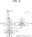
- FIG. 6 is a diagram illustrating a second example of the collection processing of the usefulness score by the DANN 10 illustrated in FIG. 4 .
- the usefulness score is calculated by Formula: (1 - yt'_max) + a, where yt'_max is the maximum value of the output yt' from the classifier, and a is the output d' from the domain identifier 103.
- FIG. 7 is a diagram for explaining moving processing of the target object 3 to the data acquisition environment 4 by the data collection system 100 shown in FIG. 2 .
- the DANN10 calculates the score of the image captured by the camera 161.
- the robot arm 2 moves the target object 3 to the data acquisition environment 4 when the score exceeds a threshold (for example, the initial value is 0).
- the target object 3 is moved to the data acquisition environment 4.
- the data-collection program selects target data (in other words, applied-data) whose confidence levels for outputs that are when the data to be collected are input to the machine learning model are lower than thresholds, and collects training data (in other words, the learning data 142) so that the confidence level for the target object 3 related to the selected target data is high.
- target data in other words, applied-data
- training data in other words, the learning data 142
- FIG. 8 is a diagram illustrating a first example of data acquisition processing by the data collection system 100 illustrated in FIG. 2 .
- FIG. 9 is a diagram illustrating a second example of the data acquisition processing performed by the data collection system 100 illustrated in FIG. 2 .
- the data collection system 100 searches for one or more parameters that maximize the score.
- the parameter p (-0.7,0.0) at which the score is the local maximum is searched.
- the parameter p (-0.7,0.3) at which the score is locally maximized at 1.4 is searched.
- the data-collection program controls the position and the posture of the camera 162 that captures the target object 3, thereby collecting the training-data (in other words, the learning data 142) so that the confidence degree becomes high.
- the data-collection program also requests the operator to perform labeling on the target object 3 for the training data (in other words, the learning data 142) collected with a high confidence.
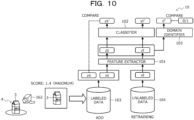
- FIG. 10 is a diagram for explaining the data addition processing and the retraining processing performed by the data collection system 100 illustrated in FIG. 2 .
- the labeling collection system 100 requests the operator to perform labelling on the image of the target 3 having the local maximum score 1.4, to add the labeled data 143 to the learning data 142.
- the data collection system 100 adds the learning data 142 to the unlabeled data 144 and performs retraining.
- FIG. 11 is a diagram illustrating calculation processing of a threshold of a score of the target object 3 by the data collection system 100 illustrated in FIG. 2 .
- the data collection system 100 After the search for the target object 3 by the camera 162 is completed, the data collection system 100 returns the target object 3 from the data acquisition environment 4 to the original position such as the belt conveyor.
- the data collection system 100 records the score of the target object 3 passing in front of the camera 161 during the use of the photographing environment and the required time t, and sets the maximum score among them as a threshold. Thereafter, the data collection system 100 uses, as the threshold, the maximum score of the product that has passed through the camera 161 in the latest t hours as the threshold until the next target object 3 is selected.
- the value selected as the threshold is "1.3", which is the maximum value from among scores when the target 3 passes in front of the camera 161 during the time t taken for data acquisition.
- FIG. 12 is a block diagram schematically illustrating an example of a hardware configuration of the data collection device 1 according to the embodiment.
- the data collection apparatus 1 includes a CPU 11, a memory unit 12, a display control unit 13, a storage device 14, an input interface (IF) 15, an external recording medium processing unit 16, and a communication IF 17.
- the memory unit 12 is an example of a storage unit, and is illustratively a read only memory (ROM), a random access memory (RAM), or the like.
- the ROM as the memory unit 12 may store a program such as a basic input/output system (BIOS).
- BIOS basic input/output system
- the software program in the memory unit 12 may be loaded into the CPU11 and executed as required.
- the RAM as the memory unit 12 may be used as a temporary recording memory or a working memory.
- the display control unit 13 is coupled to and controls the display device 131.
- the display device 131 is a device configured to display various kinds of information for an operator or the like, and may be a liquid crystal display, an organic light-emitting diode (OLED) display, a cathode ray tube (CRT), an electronic paper display, or the like.
- the display device 131 may be in combination with an input device, and may be, for example, a touch panel.
- the storage device 14 is a storage device with high IO performance, for example, a dynamic random access memory (DRAM), an SSD, a storage class memory (SCM), or an HDD.
- DRAM dynamic random access memory
- SSD SSD
- SCM storage class memory
- HDD high IO performance
- the input IF 15 may be coupled to an input device such as a mouse 151 or a keyboard 152, and may control the input device such as the mouse 151 or the keyboard 152.
- the mouse 151 and the keyboard 152 are examples of input devices. An operator performs various input operations via these input devices.
- the external recording medium processing unit 16 is configured to be able to mount the recording medium 160.
- the external recording medium processing unit 16 is configured to be able to read information stored in the recording medium 160 in a state where the recording medium 160 is mounted.
- the recording medium 160 is portable.
- the recording medium 160 is a flexible disk, an optical disk, a magnetic disk, a magneto-optical disk, a semiconductor memory, or the like.
- the external recording medium processing unit 16 may be coupled to the cameras 161, 162, and 163, to acquire a video captured by the cameras 161, 162, and 163 and control the position and the posture of the camera 162.
- the communication IF 17 is an interface for enabling communication with an external device.
- the CPU 11 is an example of the processor, and is a processing device that performs various controls and calculations.
- the CPU 11 implements various functions by executing an operating system (OS) and programs loaded into the memory unit 12.
- OS operating system
- the device for controlling the operation of whole of the data collection device 1 is not limited to the CPU 11, and may be any one of an MPU, a DSP, an ASIC, a PLD, and an FPGA, for example. Further, the device for controlling the operation of whole of the data collection device 1 may be a combination of any two or more of the CPU, the MPU, the DSP, the ASIC, the PLD, and the FPGA.
- MPU is an abbreviation of Micro Processing Unit
- DSP is an abbreviation of Digital Signal Processor
- ASIC is an abbreviation of Application Specific Integrated Circuit.
- PLD is an abbreviation of Programmable Logic Device
- FPGA is an abbreviation of Field Programmable Gate Array.
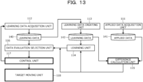
- FIG. 13 is a block diagram schematically showing an example of the software configuration of the data collection apparatus 1 illustrated in FIG. 12 .
- the CPU 11 of the data collection apparatus 1 functions as an applied-data acquisition unit 111, a learning data acquisition unit 112, a learning data creating unit 113, a learning unit 114, a difference calculation unit 115, a data-evaluation selection unit 116, a control unit 117, and a target moving unit 118.
- the applied-data acquisition unit 111 acquires an image of the target 3 captured by the camera 161, and stores the acquired image as the applied-data 141.
- the learning data acquisition unit 112 obtains an image of the target object 3 captured by the camera 162 in the data acquisition environment 4, to store the obtained image as the acquired data 140.
- the learning data creating unit 113 acquires a label, which has been assigned by the operator based on the acquired data 140, to store the acquired label as the learning data 142.
- the learning unit 114 corresponds to the feature extractor 101 and the classifier 102 of the DANN 10 illustrated in, for example, FIG. 4 .
- the learning unit 114 trains a classification model using the learning data 142.
- the difference calculation unit 115 corresponds to the domain identifier 103 of DANN10 illustrated in, for example, FIG. 4 .
- the difference calculation unit 115 calculates the difference between the applied-data 141 and the learning data 142.
- the data evaluation selection unit 116 calculates, based on the acquired data 140, a parameter of the posture of the camera 162 in which the score of the image of the target object 3 captured by the camera 162 is maximized.
- the data evaluation selection unit 116 specifies the target object 3 to be moved to the data acquisition environment 4 for which the learning unit 114 determines that the usefulness score is equal to or greater than the threshold value.
- the control unit 117 causes the learning data acquisition unit 112 to control the posture of the camera 162 based on the calculation result of the parameter of the posture by the data evaluation selection unit 116.
- the control unit 117 performs control such that the target moving unit 118 moves the target object 3 specified by the data evaluation selection unit 116 to the data acquisition environment 4 by the robot arm 2.
- the target moving unit 118 moves the target object 3 to the data acquisition environment 4 by the robot arm 2 based on the control by the control unit 117.
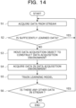
- step S1 to S6 The data collection processing in the embodiment will be described with reference to the flowchart (steps S1 to S6) illustrated in FIG. 14 .
- the applied-data acquisition unit 111 acquires the target object 3 from the camera 161 that captures the stream of the belt conveyor or the like (step S1).
- the control unit 117 determines whether the data of the target object 3 corresponds to data that has been sufficiently learned (step S2).
- Step S2 When the data of the target object 3 corresponds to data that has been sufficiently learned (YES in Step S2), the process returns to Step S1.
- the target moving unit 118 moves the target object 3 by the robot arm 2 to construct the data-acquisition environment 4 (step S3).
- the learning data creating unit 113 acquires data from the camera 162 in the data-acquisition environment 4 (step S4).
- the learning unit 114 trains the learning model (step S5).
- the applied-data acquisition unit 111 determines whether there is still any other data in the stream (step S6).
- Step S6 When there is still any other data in the stream (YES in Step S6), the process returns to Step S1.
- FIG. 15 is a graph illustrating a relationship between a learning time by inputting data and a performance of a learned model in the related example.
- FIG. 16 is a graph illustrating a relationship between a learning time by inputting data and the performance of a learned model in the embodiment.
- the learning data collection processing controls the data acquisition device such as the camera 162 to obtain the data obtained additionally.
- the learning time in other words, the number of pieces of data
- the performances of the learned models improve.
- the data collection device 1, and the data collection method in the above-described embodiment for example, the following operational effects can be achieved.
- the data collection program selects, from among data to be collected, target data having a confidence level that is for an output when the data is input to the machine learning model and is lower than a threshold, and collects, for the target object 3 regarding the selected target data, the training data so that the confidence level become higher.
- the accuracy of the machine learning model can be improved in a short learning time.
- FIG. 17 is a diagram illustrating data collection processing performed by the data collection system 100a according to the first modification.
- the data collection system 100a performs object detection in the package.
- the X-ray inspection apparatus 164 is an example of the data acquisition device, and causes a package as the target object 3 to pass in one direction by a belt conveyor.
- the X-ray inspection apparatus 165 is an example of the data acquisition device disposed in the data-acquisition environment 4a.
- the target object 3 and the package of the non-inspection target object 3a are taken in and out in both directions by a belt conveyor.
- the robot arm 2 moves the inspection target to the data-acquisition environment 4a.
- the robotic arm 2 also moves at least a portion of the stock of non-inspection target objects 3a for inspection, together with the target object 3, to the data-acquisition environment 4a.
- the way of arranging the packages in the data-acquisition environment 4a corresponds to a parameter of the data acquisition device described above with reference to FIGS. 8 and 9 , and the like, and it is possible to search for the arrangement of the packages that is difficult to detect.
- the data collection system 100a of the first modification in addition to the operational effects that can be achieved in the above-described embodiment, it is possible to increase the accuracy of a machine learning model in a short learning time even in a machine learning model for X-ray inspection such as hazardous material detection.
- FIG. 18 is a diagram illustrating data collection processing performed by the data collection system 100b according to the second modification.
- the data collection system 100b performs underwater object detection using acoustic waves.
- the speaker 166 is an example of the date acquisition device and may be referred to as an acoustic wave source.
- the microphone 167 is an example of the data acquisition device and may be referred to as a measurement device.
- the speaker 166 and the microphone 167 are attached to different submarines or unmanned underwater vehicles, respectively, and are movable in water in the data-acquisition environment 4b, and detect the target 3 by the ultrasonic radar.
- the data-acquisition environment 4b is a region surrounded by the net 5, and includes an entrance/exit 5a for taking the data-acquisition target 3 such as fish into and out of the net 5.
- the way of arranging the speaker 166 and the microphone 167 in the data-acquisition environment 4b corresponds to a parameter of the data-acquisition device described above with reference to FIGS. 8 and 9 .
- the speaker 166 and the microphone 167 can be searched for the detection of the target object 3.
- the accuracy of the machine learning model can be improved in a short learning time.
- Patent Document 1 Japanese Laid-open Patent Publication No. 2020 - 119283
Landscapes
- Engineering & Computer Science (AREA)
- Theoretical Computer Science (AREA)
- Physics & Mathematics (AREA)
- Software Systems (AREA)
- Computing Systems (AREA)
- Artificial Intelligence (AREA)
- Evolutionary Computation (AREA)
- General Physics & Mathematics (AREA)
- General Health & Medical Sciences (AREA)
- Health & Medical Sciences (AREA)
- Multimedia (AREA)
- Databases & Information Systems (AREA)
- Computer Vision & Pattern Recognition (AREA)
- Medical Informatics (AREA)
- Data Mining & Analysis (AREA)
- General Engineering & Computer Science (AREA)
- Mathematical Physics (AREA)
- Biophysics (AREA)
- Molecular Biology (AREA)
- Computational Linguistics (AREA)
- Biomedical Technology (AREA)
- Life Sciences & Earth Sciences (AREA)
- Signal Processing (AREA)
- Robotics (AREA)
- Mechanical Engineering (AREA)
- Image Analysis (AREA)
Abstract
Description
- The present disclosure relates to a data collection program, a data collection device, and a data collection method.
- In machine learning, supervised learning using labeled data may be applied to a problem of classifying products and the like.
- Since the labeled data has a higher collection cost than the unlabeled data, the labeled data may be generated by the stream-type active learning. In the stream type active learning, unlabeled data that are sequentially input are classified into known data (in other words, data whose labels can be estimated with high confidence by a model being learned) and unknown data (in other words, data whose labels cannot be classified by the model being learned), and labeling is requested for the unknown data.
-
FIG. 1 is a graph illustrating a relationship between a learning time by data input, and a performance of a learned model. - It takes time until all data assumed in an application destination of the learned model is input, and there is a concern that performance improvement cannot be expected with respect to the number of input data in a late stage of learning. In the example illustrated in
FIG. 1 , at the beginning of the learning time, pieces of data that are effective for improving the performances are likely to be collected, as indicated by the reference sign A1 (see the hatched circles). On the other hand, as the data collection progresses, pieces of data that are not effective for improving the performances (see white circles) are likely to be collected, as indicated by the reference sign A2. - According to an aspect, an object is to improve the accuracy of a machine learning model in a short learning time.
- According to an embodiment of the present disclosure, there is provided a computer-readable storage medium storing a computer program for causing a computer to execute a process of collecting training data used for training a machine learning model, the process including: selecting a target data having a lower confidence level than a predetermined value for an output when the data to be collected is input to the machine learning model; and collecting the training data so that the confidence level is increased for an object related to the selected target data.
- According to an aspect of the present invention, it is possible to increase the accuracy of a machine learning model in a short learning time.
-
-
FIG. 1 is a graph illustrating a relationship between a learning time by data input and a performance of a learned model; -
FIG. 2 is a diagram briefly explaining data collection processing by the data collection system in an embodiment; -
FIG. 3 is a diagram for explaining collection processing of labeled data and unlabeled data by the data collection system illustrated inFIG. 2 ; -
FIG. 4 is a diagram for explaining an example of the configuration of domain adversarial neural networks (DANN) used in an embodiment; -
FIG. 5 is a diagram for explaining a first example of calculation processing of a usefulness score by the DANN illustrated inFIG. 4 ; -
FIG. 6 is a diagram for explaining a second example of the calculation processing of the usefulness score by the DANN illustrated inFIG. 4 ; -
FIG. 7 is a diagram for explaining moving processing of an object to a data acquisition environment by the data collection system illustrated inFIG. 2 ; -
FIG. 8 is a diagram for explaining a first example of data acquisition processing by the data collection system illustrated inFIG. 2 ; -
FIG. 9 is a diagram for explaining a second example of data acquisition processing by the data collection system illustrated inFIG. 2 ; -
FIG. 10 is a diagram for explaining data addition processing and retraining processing by the data collection system illustrated inFIG. 2 ; -
FIG. 11 is a diagram for explaining calculation processing of a threshold value of a score of an object by the data collection system illustrated inFIG. 2 ; -
FIG. 12 is a block diagram schematically illustrating an example of a hardware configuration of a data collection apparatus according to an embodiment; -
FIG. 13 is a block diagram schematically illustrating an example of a software configuration of the data collection apparatus illustrated inFIG. 12 ; -
FIG. 14 is a flowchart for explaining data collection processing in an embodiment; -
FIG. 15 is a graph exemplifying a relationship between a learning time by inputting data and a performance of a learned model in a related example; -
FIG. 16 is a graph exemplifying a relationship between a learning time by inputting data and a performance of a learned model in an embodiment; -
FIG. 17 is a diagram for explaining data collection processing by the data collection system in the first modification; and -
FIG. 18 is a diagram for explaining data collection processing by the data collection system in the second modification. - Hereinafter, an embodiment will be described with reference to the drawings. However, the embodiments described below are merely examples, and there is no intention to exclude various modifications and applications of techniques not explicitly described in the embodiments. That is, the present embodiment can be implemented in various modifications without departing from the spirit of the present embodiment. Each drawing is not intended to include only the constituent elements shown in the drawing, and may include other functions and the like.
- In the drawings, the same reference numerals denote the same parts, and a description thereof will be omitted.
-
FIG. 2 is a diagram briefly illustrating data collection processing performed by thedata collection system 100 according to the embodiment. - The
data collection system 100 acquires a captured image of thetarget object 3 and generates a machine learning model for classifying thetarget object 3. Thedata collection system 100 actively acquires unknown data by controlling a data acquisition device such as thecameras - When data merely having a high similarity to known data is acquired, data that cannot be classified in principle, such as data of only a background or data including two or more objects, may be acquired.
- Therefore, the
data collection system 100 takes out thetarget object 3 as a single body by therobot arm 2 and performs imaging of thetarget object 3 in a space in which an imaging range is fixed, in other words, thedata acquisition environment 4. - In the
data collection system 100, thecamera 161 captures an image of thetarget 3 moving on a belt conveyor or the like, and stores the image data as applied-data 141. Therobot arm 2 grips thetarget object 3 based on the captured image data, and moves thetarget object 3 to thedata acquisition environment 4. Thecamera 162 acquires thelearning data 142 by moving the imaging range and performing imaging in the data-acquisition environment 4. Adaptation is performed between the applied-data 141 and thelearning date 142. -
FIG. 3 is a diagram for explaining collection processing of the labeleddata 143 and theunlabeled data 144 by thedata collection system 100 illustrated inFIG. 2 . - In the initial stage of machine learning, a predetermined number of pieces of labeled
data 143 for learning andunlabeled data 144 to be applied are collected. - The
camera 161 captures an image of thetarget 3 and stores the captured image as labeleddata 143. Thecamera 162 captures, while moving the imaging range, an image of thetarget object 3 moved to thedata acquisition environment 4 by therobot arm 2. Thecamera 163, which is different from thecamera 161 and thecamera 162, acquiresunlabeled data 144. -
FIG. 4 is a diagram illustrating a configuration example of aDANN 10 used in the present embodiment. - The
data collection system 100 trains a classification model using DANN 10. The DANN 10 includes afeature extractor 101, aclassifier 102, and adomain identifier 103. - The
classifier 102 is trained to estimate the label of the labeleddata 143 from the output of thefeature extractor 101. Thedomain identifier 103 is trained to estimate a data source (0: labeled data / 1: unlabeled data) from the output of thefeature extractor 101. Thefeature extractor 101 is trained so that theclassifier 102 succeeds and thedomain identifier 103 fails. - The
feature extractor 101 generates an output zs and an output zt, from an output xs that is from the labeleddata 143 and an output xt that is from theunlabeled data 144, respectively. Theclassifier 102 generates outputs ys' and yt' from the outputs zs and zt, respectively, and compares the output ys' with the output ys of the labeleddata 143. Thedomain identifier 103 generates an output d' from the outputs zs and zt, and compares the output d' with the data source (0: labeled data / 1: unlabeled data). -
FIG. 5 is a diagram illustrating a first example of the collection processing of the usefulness score by the DANN10 illustrated inFIG. 4 .FIG. 6 is a diagram illustrating a second example of the collection processing of the usefulness score by theDANN 10 illustrated inFIG. 4 . - When data that has a property close to that of the applied-
data 141 and cannot be classified by thecurrent classifier 102 is used for training, performance improvement at the application destination can be expected. Therefore, as an index indicating how much unknown data is included, the usefulness score is calculated by Formula: (1 - yt'_max) + a, where yt'_max is the maximum value of the output yt' from the classifier, and a is the output d' from thedomain identifier 103. - In the example illustrated in
FIG. 5 , since yt'_max = 0.5 and a = 0.7, the usefulness score is obtained by (1-0. 5) + 0.7 = 1.2. In the example illustrated inFIG. 5 , since yt'_max = 0.9 and α = 1.0, the usefulness score is obtained by (1 - 0. 9) + 1.0 = 1.1. -
FIG. 7 is a diagram for explaining moving processing of thetarget object 3 to thedata acquisition environment 4 by thedata collection system 100 shown inFIG. 2 . - The DANN10 calculates the score of the image captured by the
camera 161. Therobot arm 2 moves thetarget object 3 to thedata acquisition environment 4 when the score exceeds a threshold (for example, the initial value is 0). - In the example illustrated in
FIG. 7 , since the score is 0.4 and is larger than the threshold value "0", thetarget object 3 is moved to thedata acquisition environment 4. - In other words, the data-collection program selects target data (in other words, applied-data) whose confidence levels for outputs that are when the data to be collected are input to the machine learning model are lower than thresholds, and collects training data (in other words, the learning data 142) so that the confidence level for the
target object 3 related to the selected target data is high. -
FIG. 8 is a diagram illustrating a first example of data acquisition processing by thedata collection system 100 illustrated inFIG. 2 .FIG. 9 is a diagram illustrating a second example of the data acquisition processing performed by thedata collection system 100 illustrated inFIG. 2 . - By adjusting each of the two parameters x and y of the
camera 162 to capture thetarget object 3,thedata collection system 100 searches for one or more parameters that maximize the score. In the present embodiment, thedata collection system 100 searches for one parameter from the initial parameter p = (0.0,0.0) by the greedy method. - In the example illustrated in
FIG. 8 , for the parameter x, the parameter p = (-0.7,0.0) at which the score is the local maximum is searched. In the example illustrated inFIG. 9 , for the parameter y, the parameter p = (-0.7,0.3) at which the score is locally maximized at 1.4 is searched. - In other words, the data-collection program controls the position and the posture of the
camera 162 that captures thetarget object 3, thereby collecting the training-data (in other words, the learning data 142) so that the confidence degree becomes high. - The data-collection program also requests the operator to perform labeling on the
target object 3 for the training data (in other words, the learning data 142) collected with a high confidence. -
FIG. 10 is a diagram for explaining the data addition processing and the retraining processing performed by thedata collection system 100 illustrated inFIG. 2 . - The
labeling collection system 100 requests the operator to perform labelling on the image of thetarget 3 having the local maximum score 1.4, to add the labeleddata 143 to the learningdata 142. Thedata collection system 100 adds the learningdata 142 to theunlabeled data 144 and performs retraining. -
FIG. 11 is a diagram illustrating calculation processing of a threshold of a score of thetarget object 3 by thedata collection system 100 illustrated inFIG. 2 . - After the search for the
target object 3 by thecamera 162 is completed, thedata collection system 100 returns thetarget object 3 from thedata acquisition environment 4 to the original position such as the belt conveyor. Thedata collection system 100 records the score of thetarget object 3 passing in front of thecamera 161 during the use of the photographing environment and the required time t, and sets the maximum score among them as a threshold. Thereafter, thedata collection system 100 uses, as the threshold, the maximum score of the product that has passed through thecamera 161 in the latest t hours as the threshold until thenext target object 3 is selected. - In the example illustrated in
FIG. 11 , the value selected as the threshold is "1.3", which is the maximum value from among scores when thetarget 3 passes in front of thecamera 161 during the time t taken for data acquisition. -
FIG. 12 is a block diagram schematically illustrating an example of a hardware configuration of thedata collection device 1 according to the embodiment. - As illustrated in
FIG. 12 , thedata collection apparatus 1 includes aCPU 11, amemory unit 12, adisplay control unit 13, astorage device 14, an input interface (IF) 15, an external recordingmedium processing unit 16, and a communication IF 17. - The
memory unit 12 is an example of a storage unit, and is illustratively a read only memory (ROM), a random access memory (RAM), or the like. The ROM as thememory unit 12 may store a program such as a basic input/output system (BIOS). The software program in thememory unit 12 may be loaded into the CPU11 and executed as required. The RAM as thememory unit 12 may be used as a temporary recording memory or a working memory. - The
display control unit 13 is coupled to and controls thedisplay device 131. Thedisplay device 131 is a device configured to display various kinds of information for an operator or the like, and may be a liquid crystal display, an organic light-emitting diode (OLED) display, a cathode ray tube (CRT), an electronic paper display, or the like. Thedisplay device 131 may be in combination with an input device, and may be, for example, a touch panel. - The
storage device 14 is a storage device with high IO performance, for example, a dynamic random access memory (DRAM), an SSD, a storage class memory (SCM), or an HDD. - The input IF 15 may be coupled to an input device such as a
mouse 151 or akeyboard 152, and may control the input device such as themouse 151 or thekeyboard 152. Themouse 151 and thekeyboard 152 are examples of input devices. An operator performs various input operations via these input devices. - The external recording
medium processing unit 16 is configured to be able to mount therecording medium 160. The external recordingmedium processing unit 16 is configured to be able to read information stored in therecording medium 160 in a state where therecording medium 160 is mounted. In this example, therecording medium 160 is portable. For example, therecording medium 160 is a flexible disk, an optical disk, a magnetic disk, a magneto-optical disk, a semiconductor memory, or the like. The external recordingmedium processing unit 16 may be coupled to thecameras cameras camera 162. - The communication IF 17 is an interface for enabling communication with an external device.
- The
CPU 11 is an example of the processor, and is a processing device that performs various controls and calculations. TheCPU 11 implements various functions by executing an operating system (OS) and programs loaded into thememory unit 12. - The device for controlling the operation of whole of the
data collection device 1 is not limited to theCPU 11, and may be any one of an MPU, a DSP, an ASIC, a PLD, and an FPGA, for example. Further, the device for controlling the operation of whole of thedata collection device 1 may be a combination of any two or more of the CPU, the MPU, the DSP, the ASIC, the PLD, and the FPGA. Note that MPU is an abbreviation of Micro Processing Unit, DSP is an abbreviation of Digital Signal Processor, and ASIC is an abbreviation of Application Specific Integrated Circuit. In addition, PLD is an abbreviation of Programmable Logic Device, and FPGA is an abbreviation of Field Programmable Gate Array. -
FIG. 13 is a block diagram schematically showing an example of the software configuration of thedata collection apparatus 1 illustrated inFIG. 12 . - The
CPU 11 of thedata collection apparatus 1 functions as an applied-data acquisition unit 111, a learningdata acquisition unit 112, a learningdata creating unit 113, alearning unit 114, adifference calculation unit 115, a data-evaluation selection unit 116, acontrol unit 117, and atarget moving unit 118. - The applied-
data acquisition unit 111 acquires an image of thetarget 3 captured by thecamera 161, and stores the acquired image as the applied-data 141. - The learning
data acquisition unit 112 obtains an image of thetarget object 3 captured by thecamera 162 in thedata acquisition environment 4, to store the obtained image as the acquireddata 140. - The learning
data creating unit 113 acquires a label, which has been assigned by the operator based on the acquireddata 140, to store the acquired label as the learningdata 142. - The
learning unit 114 corresponds to thefeature extractor 101 and theclassifier 102 of theDANN 10 illustrated in, for example,FIG. 4 . Thelearning unit 114 trains a classification model using thelearning data 142. - The
difference calculation unit 115 corresponds to thedomain identifier 103 of DANN10 illustrated in, for example,FIG. 4 . Thedifference calculation unit 115 calculates the difference between the applied-data 141 and the learningdata 142. - The data
evaluation selection unit 116 calculates, based on the acquireddata 140, a parameter of the posture of thecamera 162 in which the score of the image of thetarget object 3 captured by thecamera 162 is maximized. The dataevaluation selection unit 116 specifies thetarget object 3 to be moved to thedata acquisition environment 4 for which thelearning unit 114 determines that the usefulness score is equal to or greater than the threshold value. - The
control unit 117 causes the learningdata acquisition unit 112 to control the posture of thecamera 162 based on the calculation result of the parameter of the posture by the dataevaluation selection unit 116. Thecontrol unit 117 performs control such that thetarget moving unit 118 moves thetarget object 3 specified by the dataevaluation selection unit 116 to thedata acquisition environment 4 by therobot arm 2. - The
target moving unit 118 moves thetarget object 3 to thedata acquisition environment 4 by therobot arm 2 based on the control by thecontrol unit 117. - The data collection processing in the embodiment will be described with reference to the flowchart (steps S1 to S6) illustrated in
FIG. 14 . - The applied-
data acquisition unit 111 acquires thetarget object 3 from thecamera 161 that captures the stream of the belt conveyor or the like (step S1). - The
control unit 117 determines whether the data of thetarget object 3 corresponds to data that has been sufficiently learned (step S2). - When the data of the
target object 3 corresponds to data that has been sufficiently learned (YES in Step S2), the process returns to Step S1. - On the other hand, when the data of the
target object 3 is not data that has been sufficiently learned (NO in Step S2), thetarget moving unit 118 moves thetarget object 3 by therobot arm 2 to construct the data-acquisition environment 4 (step S3). - The learning
data creating unit 113 acquires data from thecamera 162 in the data-acquisition environment 4 (step S4). - The
learning unit 114 trains the learning model (step S5). - The applied-
data acquisition unit 111 determines whether there is still any other data in the stream (step S6). - When there is still any other data in the stream (YES in Step S6), the process returns to Step S1.
- On the other hand, when there is no other data in the stream (NO in Step S6), the data collection processing is terminated.
-
FIG. 15 is a graph illustrating a relationship between a learning time by inputting data and a performance of a learned model in the related example.FIG. 16 is a graph illustrating a relationship between a learning time by inputting data and the performance of a learned model in the embodiment. - In the data collection processing in the relevant example illustrated in
FIG. 15 , among data that are effective for improving performances, as indicated by the reference sign B1, there are many pieces of data that are not effective for improving performances as indicated by the reference sign B2. Thus, even if the learning time (in other words, the number of learning data) increases, the performances of the learned models do not improve. - On the other hand, as indicated by reference sign C1 in
FIG. 16 , the learning data collection processing according to the embodiment controls the data acquisition device such as thecamera 162 to obtain the data obtained additionally. Thus, as the learning time (in other words, the number of pieces of data) increases, the performances of the learned models improve. - According to the data collection program, the
data collection device 1, and the data collection method in the above-described embodiment, for example, the following operational effects can be achieved. - The data collection program selects, from among data to be collected, target data having a confidence level that is for an output when the data is input to the machine learning model and is lower than a threshold, and collects, for the
target object 3 regarding the selected target data, the training data so that the confidence level become higher. - Thus, the accuracy of the machine learning model can be improved in a short learning time.
-
FIG. 17 is a diagram illustrating data collection processing performed by thedata collection system 100a according to the first modification. - In the first modification, the
data collection system 100a performs object detection in the package. - The
X-ray inspection apparatus 164 is an example of the data acquisition device, and causes a package as thetarget object 3 to pass in one direction by a belt conveyor. - The
X-ray inspection apparatus 165 is an example of the data acquisition device disposed in the data-acquisition environment 4a. Thetarget object 3 and the package of thenon-inspection target object 3a are taken in and out in both directions by a belt conveyor. - The
robot arm 2 moves the inspection target to the data-acquisition environment 4a. Therobotic arm 2 also moves at least a portion of the stock of non-inspection target objects 3a for inspection, together with thetarget object 3, to the data-acquisition environment 4a. - The way of arranging the packages in the data-acquisition environment 4a corresponds to a parameter of the data acquisition device described above with reference to
FIGS. 8 and9 , and the like, and it is possible to search for the arrangement of the packages that is difficult to detect. - According to the
data collection system 100a of the first modification, in addition to the operational effects that can be achieved in the above-described embodiment, it is possible to increase the accuracy of a machine learning model in a short learning time even in a machine learning model for X-ray inspection such as hazardous material detection. -
FIG. 18 is a diagram illustrating data collection processing performed by thedata collection system 100b according to the second modification. - In the second modification, the
data collection system 100b performs underwater object detection using acoustic waves. - The
speaker 166 is an example of the date acquisition device and may be referred to as an acoustic wave source. Themicrophone 167 is an example of the data acquisition device and may be referred to as a measurement device. Thespeaker 166 and themicrophone 167 are attached to different submarines or unmanned underwater vehicles, respectively, and are movable in water in the data-acquisition environment 4b, and detect thetarget 3 by the ultrasonic radar. - The data-
acquisition environment 4b is a region surrounded by the net 5, and includes an entrance/exit 5a for taking the data-acquisition target 3 such as fish into and out of thenet 5. - The way of arranging the
speaker 166 and themicrophone 167 in the data-acquisition environment 4b corresponds to a parameter of the data-acquisition device described above with reference toFIGS. 8 and9 . Thespeaker 166 and themicrophone 167 can be searched for the detection of thetarget object 3. - According to the
data collection system 100b in the second modification, in addition to the operation and effect that can be achieved in the above-described embodiment, even in the machine learning model for searching for fish or the like in water by the ultrasonic radar, the accuracy of the machine learning model can be improved in a short learning time. - The disclosed technique is not limited to the above-described embodiments, and various modifications can be made without departing from the spirit of the present embodiments. The configurations and processes of the present embodiment can be selected as necessary, or may be combined as appropriate.
- [Patent Document 1]
Japanese Laid-open Patent Publication No. 2020 - 119283 -
- 1: data collection device
- 2: robot arm
- 3: object
- 3a: non-target object
- 4, 4a, 4b: data-acquisition environment
- 5: net
- 5a: doorway
- 10: feature extractor
- 11: CPU
- 12: memory unit
- 13: display control unit
- 14: storage device
- 15: input IF
- 16: external recording medium processing unit
- 17: communication IF
- 100, 100a, and 100b: data collection system
- 101: feature extractor
- 102: classifier
- 103: domain identifier
- 111: applied-data acquisition unit
- 112: learning data acquisition unit
- 113: learning data creating unit
- 114: learning unit
- 115: difference calculation unit
- 116: data evaluation selection unit
- 117: control unit
- 118: target moving unit
- 131: display device
- 140: acquired data
- 141: applied-data
- 142: learning data
- 143: labeled data
- 144: unlabeled data
- 151: mouse
- 152: keyboard
- 160: recording medium
- 161, 162, and 163: camera
- 164 and 165: X-ray inspection apparatus
- 166: speaker
- 167: microphone
Claims (9)
- A data collection program for causing a computer, which is configured to collect training data used for training a machine learning model, to perform processing comprising:selecting a target data having a confidence level lower than a predetermined value, the confidence level corresponding to a confidence for an output from the machine learning model when collected data is input into the machine learning model; andcollecting, for a target object related to the selected target data, the training data such that the confidence is high.
- The data collection program according to claim 1, the processing further comprising:
collecting the training data so that the confidence is increased by controlling a position and an orientation of a camera that captures the target object. - The data collection program according to claim 1 or 2, the processing further comprising:
requesting an operator to perform labeling of the target object, on the training data collected so as to increase the confidence. - A data collection apparatus for collecting training data used for training a machine learning model, the data collection apparatus comprising a processor configured to perform processing comprising:selecting a target data having a confidence level lower than a predetermined value, the confidence level corresponding to a confidence for an output from the machine learning model when collected data is input into the machine learning model; andcollecting, for a target object related to the selected target data, the training data such that the confidence is high.
- The data collection apparatus according to claim 4, the processing further comprising:
collecting the training data so that the confidence is increased by controlling a position and an orientation of a camera that captures the target object. - The data collection apparatus according to claim 4 or 5, the processing further comprising:
requesting an operator to perform labeling of the target object, on the training data collected so as to increase the confidence. - A data collection method implemented by a computer configured to collect training data used for training a machine learning model, the data collection method comprising:selecting a target data having a confidence level lower than a predetermined value, the confidence level corresponding to a confidence for an output from the machine learning model when collected data is input into the machine learning model; andcollecting, for a target object related to the selected target data, the training data such that the confidence is high.
- The data collection method according to claim 7, further comprising:
collecting the training data so that the confidence is increased by controlling a position and an orientation of a camera that captures the target object. - The data collection method according to claim 7 or 8, further comprising:
requesting an operator to perform labeling of the target object, on the training data collected so as to increase the confidence.
Applications Claiming Priority (1)
| Application Number | Priority Date | Filing Date | Title |
|---|---|---|---|
| PCT/JP2021/035084 WO2023047531A1 (en) | 2021-09-24 | 2021-09-24 | Data collection program, data collection device, and data collection method |
Publications (2)
| Publication Number | Publication Date |
|---|---|
| EP4407526A1 true EP4407526A1 (en) | 2024-07-31 |
| EP4407526A4 EP4407526A4 (en) | 2024-11-13 |
Family
ID=85719354
Family Applications (1)
| Application Number | Title | Priority Date | Filing Date |
|---|---|---|---|
| EP21958407.5A Withdrawn EP4407526A4 (en) | 2021-09-24 | 2021-09-24 | DATA COLLECTION PROGRAM, DATA COLLECTION DEVICE AND DATA COLLECTION METHOD |
Country Status (5)
| Country | Link |
|---|---|
| US (1) | US20240193924A1 (en) |
| EP (1) | EP4407526A4 (en) |
| JP (1) | JPWO2023047531A1 (en) |
| CN (1) | CN117916746A (en) |
| WO (1) | WO2023047531A1 (en) |
Family Cites Families (4)
| Publication number | Priority date | Publication date | Assignee | Title |
|---|---|---|---|---|
| JP5108563B2 (en) * | 2008-03-03 | 2012-12-26 | 日本放送協会 | Neural network device, robot camera control device using the same, and neural network program |
| JP7224931B2 (en) | 2019-01-24 | 2023-02-20 | 株式会社リクルート | LEARNING MODEL GENERATOR, PROGRAM, AND METHOD OF MANUFACTURING TERMINAL DEVICE |
| WO2021084623A1 (en) * | 2019-10-29 | 2021-05-06 | 富士通株式会社 | Degradation suppression program, degradation suppression method, and information processing device |
| US12475408B2 (en) * | 2020-08-11 | 2025-11-18 | Mitsubishi Electric Corporation | Learning system, learning method, and recording medium |
-
2021
- 2021-09-24 JP JP2023549255A patent/JPWO2023047531A1/ja active Pending
- 2021-09-24 WO PCT/JP2021/035084 patent/WO2023047531A1/en not_active Ceased
- 2021-09-24 EP EP21958407.5A patent/EP4407526A4/en not_active Withdrawn
- 2021-09-24 CN CN202180102150.1A patent/CN117916746A/en active Pending
-
2024
- 2024-02-19 US US18/581,044 patent/US20240193924A1/en active Pending
Also Published As
| Publication number | Publication date |
|---|---|
| JPWO2023047531A1 (en) | 2023-03-30 |
| US20240193924A1 (en) | 2024-06-13 |
| EP4407526A4 (en) | 2024-11-13 |
| WO2023047531A1 (en) | 2023-03-30 |
| CN117916746A (en) | 2024-04-19 |
Similar Documents
| Publication | Publication Date | Title |
|---|---|---|
| Akyon et al. | Slicing aided hyper inference and fine-tuning for small object detection | |
| US20200226751A1 (en) | Surgical workflow and activity detection based on surgical videos | |
| CN111695622B (en) | Identification model training method, identification method and identification device for substation operation scene | |
| EP3673417B1 (en) | System and method for distributive training and weight distribution in a neural network | |
| CN115705714A (en) | System and method for analyzing a work area | |
| WO2019040213A1 (en) | Adaptive real-time detection and examination network (arden) | |
| CA3235569A1 (en) | Automated bin-picking based on deep learning | |
| Chatterjee et al. | Real-time object detection and recognition on low-compute humanoid robots using deep learning | |
| Fang et al. | Small-objectness sensitive detection based on shifted single shot detector | |
| EP3576026A1 (en) | Information processing device, information processing method, and program | |
| KR102882856B1 (en) | Skeleton based action recognition Method, Processor and Computer Program | |
| EP4407526A1 (en) | Data collection program, data collection device, and data collection method | |
| Park et al. | Deep learning-based drone detection with SWIR cameras | |
| Nikpour | Deep reinforcement learning in human activity recognition: A survey | |
| Tsonkov et al. | Software architecture for object detection in images based on color features with integrated artificial intelligence | |
| Subramanian et al. | Enhancing Object Detection through Auditory-Visual Fusion on Raspberry Pi and FogBus | |
| Alve | Deep Learning and Hybrid Approaches for Dynamic Scene Analysis, Object Detection and Motion Tracking | |
| Fang et al. | Understanding human-object interaction in RGB-D videos for human robot interaction | |
| Zhou et al. | SCNet-YOLO: a symmetric convolution network for multi-scenario ship detection based on YOLOv7 | |
| Meena et al. | Hybrid neural network architecture for multi-label object recognition using feature fusion | |
| Luo et al. | Real-time Visual SLAM Based on Lightweight PSPNet Network. | |
| CN116912934A (en) | Robust 2D human pose estimation method and device based on IMU and RGB images | |
| Dong et al. | Experimental evaluation of GAN-based one-class anomaly detection on office monitoring | |
| Chu et al. | Intelligent 6-DoF robotic grasping and manipulation system using deep learning | |
| Zhao et al. | Class-Agnostic Detection of Unknown Objects from Foreground Improves Robust Open World Object Detection |
Legal Events
| Date | Code | Title | Description |
|---|---|---|---|
| STAA | Information on the status of an ep patent application or granted ep patent |
Free format text: STATUS: THE INTERNATIONAL PUBLICATION HAS BEEN MADE |
|
| PUAI | Public reference made under article 153(3) epc to a published international application that has entered the european phase |
Free format text: ORIGINAL CODE: 0009012 |
|
| STAA | Information on the status of an ep patent application or granted ep patent |
Free format text: STATUS: REQUEST FOR EXAMINATION WAS MADE |
|
| 17P | Request for examination filed |
Effective date: 20240216 |
|
| AK | Designated contracting states |
Kind code of ref document: A1 Designated state(s): AL AT BE BG CH CY CZ DE DK EE ES FI FR GB GR HR HU IE IS IT LI LT LU LV MC MK MT NL NO PL PT RO RS SE SI SK SM TR |
|
| REG | Reference to a national code |
Ref country code: DE Ref legal event code: R079 Free format text: PREVIOUS MAIN CLASS: G06N0020000000 Ipc: G06N0003091000 |
|
| A4 | Supplementary search report drawn up and despatched |
Effective date: 20241015 |
|
| RIC1 | Information provided on ipc code assigned before grant |
Ipc: G06V 10/764 20220101ALN20241009BHEP Ipc: H04N 23/695 20230101ALI20241009BHEP Ipc: H04N 23/61 20230101ALI20241009BHEP Ipc: G06V 10/778 20220101ALI20241009BHEP Ipc: G06V 10/776 20220101ALI20241009BHEP Ipc: G06V 10/774 20220101ALI20241009BHEP Ipc: B25J 9/16 20060101ALI20241009BHEP Ipc: G06N 20/00 20190101ALI20241009BHEP Ipc: G06N 3/094 20230101ALI20241009BHEP Ipc: G06N 3/0895 20230101ALI20241009BHEP Ipc: G06N 3/09 20230101ALI20241009BHEP Ipc: G06N 3/091 20230101AFI20241009BHEP |
|
| DAV | Request for validation of the european patent (deleted) | ||
| DAX | Request for extension of the european patent (deleted) | ||
| STAA | Information on the status of an ep patent application or granted ep patent |
Free format text: STATUS: THE APPLICATION IS DEEMED TO BE WITHDRAWN |
|
| 18D | Application deemed to be withdrawn |
Effective date: 20250507 |