EP4407483A1 - Training bev object detection models - Google Patents
Training bev object detection models Download PDFInfo
- Publication number
- EP4407483A1 EP4407483A1 EP23153722.6A EP23153722A EP4407483A1 EP 4407483 A1 EP4407483 A1 EP 4407483A1 EP 23153722 A EP23153722 A EP 23153722A EP 4407483 A1 EP4407483 A1 EP 4407483A1
- Authority
- EP
- European Patent Office
- Prior art keywords
- confidence values
- subset
- predicted
- pixels
- model
- Prior art date
- Legal status (The legal status is an assumption and is not a legal conclusion. Google has not performed a legal analysis and makes no representation as to the accuracy of the status listed.)
- Withdrawn
Links
Images


Classifications
-
- G—PHYSICS
- G06—COMPUTING OR CALCULATING; COUNTING
- G06F—ELECTRIC DIGITAL DATA PROCESSING
- G06F18/00—Pattern recognition
- G06F18/20—Analysing
- G06F18/21—Design or setup of recognition systems or techniques; Extraction of features in feature space; Blind source separation
- G06F18/214—Generating training patterns; Bootstrap methods, e.g. bagging or boosting
-
- G—PHYSICS
- G06—COMPUTING OR CALCULATING; COUNTING
- G06T—IMAGE DATA PROCESSING OR GENERATION, IN GENERAL
- G06T7/00—Image analysis
- G06T7/70—Determining position or orientation of objects or cameras
-
- G—PHYSICS
- G06—COMPUTING OR CALCULATING; COUNTING
- G06V—IMAGE OR VIDEO RECOGNITION OR UNDERSTANDING
- G06V20/00—Scenes; Scene-specific elements
- G06V20/50—Context or environment of the image
- G06V20/56—Context or environment of the image exterior to a vehicle by using sensors mounted on the vehicle
-
- G—PHYSICS
- G06—COMPUTING OR CALCULATING; COUNTING
- G06F—ELECTRIC DIGITAL DATA PROCESSING
- G06F18/00—Pattern recognition
- G06F18/20—Analysing
- G06F18/24—Classification techniques
- G06F18/241—Classification techniques relating to the classification model, e.g. parametric or non-parametric approaches
- G06F18/2415—Classification techniques relating to the classification model, e.g. parametric or non-parametric approaches based on parametric or probabilistic models, e.g. based on likelihood ratio or false acceptance rate versus a false rejection rate
-
- G—PHYSICS
- G06—COMPUTING OR CALCULATING; COUNTING
- G06T—IMAGE DATA PROCESSING OR GENERATION, IN GENERAL
- G06T7/00—Image analysis
- G06T7/60—Analysis of geometric attributes
- G06T7/62—Analysis of geometric attributes of area, perimeter, diameter or volume
-
- G—PHYSICS
- G06—COMPUTING OR CALCULATING; COUNTING
- G06V—IMAGE OR VIDEO RECOGNITION OR UNDERSTANDING
- G06V10/00—Arrangements for image or video recognition or understanding
- G06V10/10—Image acquisition
- G06V10/12—Details of acquisition arrangements; Constructional details thereof
- G06V10/14—Optical characteristics of the device performing the acquisition or on the illumination arrangements
- G06V10/143—Sensing or illuminating at different wavelengths
-
- G—PHYSICS
- G06—COMPUTING OR CALCULATING; COUNTING
- G06V—IMAGE OR VIDEO RECOGNITION OR UNDERSTANDING
- G06V10/00—Arrangements for image or video recognition or understanding
- G06V10/20—Image preprocessing
- G06V10/25—Determination of region of interest [ROI] or a volume of interest [VOI]
-
- G—PHYSICS
- G06—COMPUTING OR CALCULATING; COUNTING
- G06V—IMAGE OR VIDEO RECOGNITION OR UNDERSTANDING
- G06V10/00—Arrangements for image or video recognition or understanding
- G06V10/70—Arrangements for image or video recognition or understanding using pattern recognition or machine learning
- G06V10/764—Arrangements for image or video recognition or understanding using pattern recognition or machine learning using classification, e.g. of video objects
-
- G—PHYSICS
- G06—COMPUTING OR CALCULATING; COUNTING
- G06V—IMAGE OR VIDEO RECOGNITION OR UNDERSTANDING
- G06V10/00—Arrangements for image or video recognition or understanding
- G06V10/70—Arrangements for image or video recognition or understanding using pattern recognition or machine learning
- G06V10/766—Arrangements for image or video recognition or understanding using pattern recognition or machine learning using regression, e.g. by projecting features on hyperplanes
-
- G—PHYSICS
- G06—COMPUTING OR CALCULATING; COUNTING
- G06V—IMAGE OR VIDEO RECOGNITION OR UNDERSTANDING
- G06V20/00—Scenes; Scene-specific elements
- G06V20/50—Context or environment of the image
- G06V20/56—Context or environment of the image exterior to a vehicle by using sensors mounted on the vehicle
- G06V20/58—Recognition of moving objects or obstacles, e.g. vehicles or pedestrians; Recognition of traffic objects, e.g. traffic signs, traffic lights or roads
-
- G—PHYSICS
- G06—COMPUTING OR CALCULATING; COUNTING
- G06V—IMAGE OR VIDEO RECOGNITION OR UNDERSTANDING
- G06V2201/00—Indexing scheme relating to image or video recognition or understanding
- G06V2201/07—Target detection
Definitions
- the present disclosure relates to a computer-implemented method for training a birds-eye-view (BEV) object detection model, a BEV object detection model, a method for BEV object detection using the trained BEV object detection model as well as a corresponding computer program, device and vehicle.
- BEV birds-eye-view
- ADAS advanced driving assistance systems
- These sensor techniques for example include vision-based sensors (e.g., cameras), Light detection and Ranging (LiDAR) sensors or short-, medium-, or long-range radar.
- Cameras for example provide accurate semantic information, but less reliable depth information.
- Radar in general provides robust information regarding distance and velocity but is highly sensitive and lacks high resolution due to sparsity issues.
- LiDAR provides accurate 3D point clouds, this also comes with the issue of expensive computational costs.
- LiDAR is often used for environment mapping, blind spot detection or park assistance.
- Cameras are often used for specific detection tasks (e.g., traffic sign recognition, lane departure warning), short-, medium-range radar for cross traffic alert, blind spot detection or rear collision warning and long-range radar for adaptive cruise control, pedestrian detection, emergency braking or collision avoidance.
- sensors like radar or LiDAR deliver a 3-dimensional instead of a 2-dimensional view including distance to objects. Furthermore, these sensors can only "see” up until the first point(s) of reflection resulting in a mere representation of outlines of the object. The area behind these first point(s) remains unobserved. Accordingly, object detection happens in largely information free areas, which may negatively affect the prediction accuracy - especially when simply applying a centerness approach (i.e., using center pixels of an image for detection) because the center of the object is in most cases within this information free area. Therefore, also corresponding methods used for training underlying artificial intelligence (AI) models have to be adapted to be able to handle these differences in corresponding training data.
- AI artificial intelligence
- An aspect of the present invention relates to a computer-implemented method for training a birds-eye-view (BEV) object detection model, the method comprising the steps of: inputting a training sample into the model, wherein the training sample comprises: a BEV image comprising a plurality of pixels; and a plurality of target confidence values, wherein each pixel of the plurality of pixels is associated with a target confidence value of the plurality of target confidence values; receiving as output from the model at least a plurality of predicted confidence values, wherein each predicted confidence value is associated with a pixel of the plurality of pixels; and adjusting a parameter set of the model according to a loss, wherein the loss is based at least on the plurality of predicted confidence values and the plurality of target confidence values.
- BEV birds-eye-view
- the model may thus be able to detect corresponding object shapes and assign predicted confidence values to each pixel based on which an efficient (i.e., reliable and accurate) classification and/or regression can be conducted.
- a target confidence value of the plurality of target confidence values indicates an uncertainty value corresponding to the pixel of the plurality of pixels associated with the target confidence value; and wherein the plurality of target confidence values indicates a distribution of uncertainty values associated with the plurality of pixels.
- a shape of the distribution of uncertainty values depends on at least one of: a distance, position, rotation, size and/or class of an object within the BEV image.
- Providing different shapes e.g., “backline” if object information is available about the back part of an object, “L-Shape” if object information is available about the back part and a right or left part of the object or “U-shape” if object information is available about the back, right and left part of the object) increases the models accuracy when detecting objects and predicting corresponding confidence values.
- adjusting the parameter set of the model comprises: determining a subset of the plurality of predicted confidence values; and wherein the loss is based on the subset of the plurality of predicted confidence values and a corresponding subset of the plurality of target confidence values.
- Limiting the prediction to a subset and thus adjusting of the parameter set of the model decreases the computational overhead of the training and may thus result in a faster convergence of the training.
- determining the subset of the plurality of predicted confidence values comprises: selecting the subset of the plurality of predicted confidence values based on label information associated with a subset of the plurality of pixels corresponding to the subset of the plurality of predicted confidence values.
- Basing the decision regarding selection of the subset on label information has the advantage of being less dependent from the underlying sensor (e.g., already preprocessed data may be used instead of raw sensor data).
- determining the subset of the plurality of predicted confidence values comprises: selecting the subset of the plurality of predicted confidence values based on sensor information associated with a subset of the plurality of pixels corresponding to the subset of the plurality of predicted confidence values.
- Basing the decision regarding selection of the subset on (available) sensor information has the advantage of having a data driven decision. This means, that only pixels which are actually backed up by sensor data (e.g., if input value of the sensor at the specific section is larger than a threshold depending on characteristics on the input data such as noise etc.) are eligible for being a target pixel.
- determining the subset of the plurality of predicted confidence values comprises: selecting the subset of the plurality of predicted confidence values based on a plurality of object detection scores; and wherein each object detection score of the plurality of object detection scores is associated with a pixel of a subset of the plurality of pixels corresponding to the subset of the plurality of predicted confidence values.
- Basing the decision regarding selection of the subset on actual object detection scores i.e., the model itself decides which pixels to select without further information like labels or sensor-back up
- IoU and/or the highest predicted confidence values may result in the model learning the detection with less biasing and thus may result in a better generalization.
- the training sample further comprises a plurality of target value sets; wherein each pixel of the plurality of pixels is associated with a target value set of the plurality of target value sets; wherein the output of the model further comprises a plurality of predicted value sets; and wherein adjusting the parameter set of the model is further based on a loss between the plurality of predicted value sets and the plurality of target value sets.
- the model may also be trained to predict a respective set of target values (e.g., usable for classification and/or regression such as binary classification whether pixel is part of a bounding box, left top and right bottom coordinates of the ground truth (GT) bounding box, class label of the object corresponding to the GT bounding box or distances from the pixel position to the respective boundaries of the GT bounding box).
- target values e.g., usable for classification and/or regression such as binary classification whether pixel is part of a bounding box, left top and right bottom coordinates of the ground truth (GT) bounding box, class label of the object corresponding to the GT bounding box or distances from the pixel position to the respective boundaries of the GT bounding box.
- each pixel of the plurality of pixels is associated with an angle value and a distance value within the BEV image; or each pixel of the plurality of pixels is associated with first cartesian coordinate and a second cartesian coordinate.
- the additional information associated with a pixel provides a way to more accurately determine the importance/confidence of the pixel. For example, based on the distance and/or rotation a respective shape of the object boundaries may be determined.
- Another aspect relates to a computer-implemented method for BEV object detection, the method comprising the steps of: obtaining a BEV image comprising a plurality of pixels; inputting the BEV image into a BEV object detection model trained according to a method as outlined above; receiving, from the model, an output comprising at least a plurality of predicted confidence values; and detecting an object within the BEV image using the output of the model.
- the output of the model further comprises a plurality of predicted value sets; and wherein detecting the object within the BEV image comprises applying the plurality of predicted confidence values on the plurality of predicted value sets.
- Applying the confidence values on the predicted value sets may have the effect of filtering the less important pixels. As a result, only the important target pixel(s) are used for the respective classification and/or regression task.
- Another aspect relates to a BEV object detection mode trained according to the method as outlined above.
- Another aspect relates to a data-processing device comprising means configured to perform the method(s) as outlined above and/or comprises the BEV object detection model as outlined above.
- Another aspect of the invention relates to a computer program comprising instructions, which when executed by a computer, causes the computer to perform the method(s) as outlined above.
- Yet another aspect of the invention relates to a vehicle comprising the aforementioned data-processing device and/or the BEV object detection model.
- Fig. 1 depicts a traffic scenario 100 comprising an ego vehicle 105 on a road with road boundaries (indicated by the black vertical lines extending from top to bottom) and two further vehicles 110 and 115.
- the intended driving direction of the three vehicles 105, 110 and 115 is indicated by the dashed arrows.
- vehicle 105 and vehicle 110 While vehicle 105 and vehicle 110 are moving, vehicle 115 may be in a parking position.
- Vehicle 105 may be equipped with sensors (e.g., radar, LiDAR etc.) observing and measuring a surrounding of the vehicle 105 as indicated by the signal waves 120.
- Vehicles 110 and 115 are represented by their corresponding bounding box, wherein each corner point is marked as P 0 - P 3 depending on a distance between the respective corner point to the vehicle 105.
- the observed and measured sensor data may allow to generate a birds-eye view (BEV) image/representation of the traffic scenario 100.
- BEV birds-eye view
- the BEV image generated this way may be used as one or more training data sample(s) for training a corresponding BEV object detection model.
- Training a BEV object detection model may comprise three main steps.
- the training sample may comprise a BEV image.
- the BEV image may comprise a plurality of pixels. Each pixel may be associated with an angle value and distance value within the BEV image (i.e., a polar representation). Each pixel may be associated with a first cartesian coordinate and a second cartesian coordinate (i.e., cartesian grid representation).
- the training sample may comprise a plurality of target confidence values. Each pixel of the plurality of pixels may be associated with a target confidence value of the plurality of target confidence values. The target confidence value may indicate an uncertainty value corresponding to the pixel associated with the target confidence value. Accordingly, a distribution of uncertainty values may be indicted by the plurality of target confidence values.
- a shape of the distribution may thereby depend on properties (e.g., distance, position, rotation, size and/or class) of an object within the BEV image.
- the training sample may further comprise a plurality of target value sets (e.g., classification and/or regression values) for each pixel.
- Determining the correct values for the plurality of target confidence values is essential for the training to be effective.
- a distribution of the values that represents a high value e.g., 1
- edges i.e., edge points of the object which are hit by the respective sensor
- decay to value o There are different metrics suitable for determining such a distribution depending on the input data or the position, rotation, distance etc. of the corresponding object.
- Equation (1) w point focuses the weights on the closest corner point, while equation (2) w L-shape focuses the weights along the two closest sides and w backline focuses the weights along the closest side.
- L2 refers to the L2 distance between the respective points
- distance refers to the shortest distance between the respective point and the line between the two respective points provided as arguments for the Line function (e.g., a linear line function to connect the respective points).
- the scale factors may be used to control the spread of the targets based on the introduced sensor inaccuracies. Which equation is to be used may be selected for example based on the rotation of the object or the distance.
- equation (3) may be preferred instead of equation (2), as it is much less likely to see the third corner point P 2 .
- equation (3) may be preferred instead of equation (2), as it is much less likely to see the third corner point P 2 .
- the rotation is less than 20 degrees also equation (3) may be used.
- determining the values e.g., use different weightings depending on object size, or take the two closest points to the object as active area for target selection. Further aspects may also consider to further weigh the scale i.e., the sensor-based inaccuracy by for example applying a respect inaccuracy margin (e.g., in pixels around the assumed boundary pixels) based on the distance.
- a respect inaccuracy margin e.g., in pixels around the assumed boundary pixels
- the output may comprise at least a plurality of predicted confidence values. Each predicted confidence value may be associated with a pixel of the BEV image.
- the output may further comprise a plurality of predicted value sets (e.g., classification and/or regression values).
- the loss may be based (at least) on the plurality of predicted confidence values and the plurality of target confidence values.
- the loss may be further based on the plurality of predicted value sets and the plurality of target value sets.
- Adjusting the parameter set of the model may comprise determining a subset (e.g., by setting a limit of selected values via a threshold and thus reducing the number of values used for adjusting) of the plurality of predicted confidence values. The loss may then be based only on the subset of the plurality of predicted confidence values and a corresponding subset of the plurality of target confidence values.
- a first approach may be referred to as label-based approach. Accordingly, the subset may be selected based on label information associated with a subset of the plurality of pixels corresponding to the subset of the plurality of predicted confidence values.
- a second approach may be referred to as sensor-based approach. Accordingly, the subset may be selected based on sensor information associated with the subset of pixels corresponding to the subset of the plurality of predicted confidence values.
- a third approach may be referred to as performance-based approach. Accordingly, selecting the subset of the plurality of predicted confidence values may be based on a plurality of object detection scores (e.g., highest Intersection over Union, highest confidence value etc.). Each object detection score may be associated with a pixel of the subset of the plurality of pixels corresponding the subset of the plurality of predicted confidence values. These approaches may be combined.
- object detection scores e.g., highest Intersection over Union, highest confidence value etc.
- the generated BEV image comprising a plurality of pixels may be inputted into the trained BEV object detection model.
- the model may then output at least a plurality of predicted confidence values.
- the model output may further comprise a plurality of predicted value sets (e.g., classification and/or regression values).
- Detecting an object within the BEV image may comprise applying (e.g., multiplying, or other suitable arithmetic operations) the plurality of predicted confidence values on the plurality of predicted value sets.
- vehicle 110 and vehicle 115 may be detected as objects.
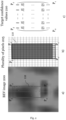
- Fig. 2 illustrates a first training sample for training a BEV object detection model according to aspects of the present invention.
- Section a) of Fig. 2 illustrates a BEV image 200.
- the BEV image 200 may relate to vehicle 110 of Fig. 1 .
- the BEV image 200 may be generated based on radar signals 120 from vehicle 105.
- Points P 0 and P 1 relate to points of vehicle 110 being hit first from the corresponding radar signal 120 of vehicle 105.
- the shape/outline of vehicle 110 may be considered as a backline. This is because the radar signal 120 of vehicle 105 solely covered information from behind (i.e., from the back part of vehicle 110).
- Section b) of Fig. 2 illustrates an abstraction of a plurality of pixels 205 of the BEV image 200.
- Pixels P 0 and P 1 again relate to the points of the vehicle 110 being hit first from the corresponding radar signal 120 of vehicle 105. The pixels between these points are considered as the target pixels the model shall learn to detect and which may then be considered for the further classification and/or regression task.
- further pixels may be considered as target pixels depending on the assigned confidence values (i.e., if the assigned confidence values are high enough which may be determined using a respective threshold).
- Section c) of Fig. 2 illustrates a corresponding plurality of target confidence values 210.
- These may be used during training of a corresponding BEV object detection model as target values (e.g., to guide the adjusting of a set of parameters of the model, i.e., optimizing the model).
- the values of the target confidence values are chosen to mirror the actual confidence (e.g., regarding information availability).
- the corresponding confidence values equal 1. The more far behind this backline, the less information is available about these parts/areas of vehicle 110.
- the confidence values also decrease accordingly (e.g., from 0.9 to .05 to 0 at the most far line of the bounding box of vehicle 110).
- a threshold for cutting of confidence values. For example, a threshold would be set to 0.9. Accordingly, values below 0.9 would be cut off and set to o. In the shown example, all values of the target confidence values 210 except the values of the 2 rows having values of 0.9 and 1 would be set to 0.
- the respective distribution of the target confidence values 210 may depend on the adjusted value of the scale of equation 3.
- the value of the scale factor may inter alia depend on the sensor accuracy. If a sensor is very accurate, a distribution of the target confidence values can be less balanced, e.g., 1, 0.9, 0.8, 0.7 and 0 for the remaining pixels. In this case, the threshold would be set to 0.7. If a sensor is less accurate, a distribution of the target confidence values can be more balanced (e.g., 1, 0.9, 0.8 ... 0.05, 0 as shown in section 2c)). In this case, the threshold would be set to 0.
- Fig. 3 illustrates a second training sample for training a BEV object detection model according to aspects of the present invention.
- Section a) of Fig. 3 illustrates a BEV image 300.
- the BEV image 300 may relate to vehicle 115 of Fig. 1 .
- the BEV image 300 may be generated based on radar signals 120 from vehicle 105.
- Points P 0 , P 1 and P 2 relate to points of vehicle 115 being hit first from the corresponding radar signal 120 of vehicle 105.
- the shape/outline of vehicle 115 may be considered as a L-shape. This is because the radar signal 120 of vehicle 105 solely covered information from behind (i.e., from the back part of vehicle 115) and from right (i.e., from the right side of vehicle 115).
- Section b) of Fig. 3 illustrates an abstraction of a plurality of pixels 305 of the BEV image 300.
- Pixels P 0 , P 1 and P 2 again relate to the points of the vehicle 115 being hit first from the corresponding radar signal 120 of vehicle 105.
- the pixels in the L-shape between these points are considered as the target pixels the model shall learn to detect and which are then considered for the further classification and/or regression task.
- further pixels may be considered as target pixels depending on the assigned confidence values (i.e., if the assigned confidence values are high enough which may be determined using a respective threshold).
- Section c) of Fig. 3 illustrates a corresponding plurality of target confidence values 310.
- These may be used during training of a corresponding BEV object detection model as target values (e.g., to guide the adjusting of a set of parameters of the model, i.e., optimizing the model).
- target values e.g., to guide the adjusting of a set of parameters of the model, i.e., optimizing the model.
- a threshold for cutting of confidence values For example, a threshold would be set to 0.9. Accordingly, values below 0.9 would be cut off and set to 0. In the shown example, all values of the target confidence values 310 except the values of the 2 rows and columns having values of 0.9 and 1 would be set to 0.
- the respective distribution of the target confidence values 310 may depend on the adjusted value of the scale of equation 3. As explained with respect to equation 3, the value of the scale factor may inter alia depend on the sensor accuracy. If a sensor is very accurate, a distribution of the target confidence values can be less balanced. For example, the distribution may then only include confidence values between 1 to 0.7 while the remaining values are cut off to 0 by defining the threshold respectively. If a sensor is less accurate, a distribution of the target confidence values can be more balanced. For example, the confidence values may then decrease evenly from 1 to 0 as shown in section 3c) by the values of the target confidence values 310.
- the method(s) according to the present invention may be implemented in terms of a computer program which may be executed on any suitable data processing device comprising means (e.g., a memory and one or more processors operatively coupled to the memory) being configured accordingly.
- the computer program may be stored as computer-executable instructions on a non-transitory computer-readable medium.
- Embodiments of the present disclosure may be realized in any of various forms.
- the present invention may be realized as a computer-implemented method, a computer-readable memory medium, or a computer system.
- a non-transitory computer-readable memory medium may be configured so that it stores program instructions and/or data, where the program instructions, if executed by a computer system, cause the computer system to perform a method, e.g., any of the method embodiments described herein, or, any combination of the method embodiments described herein, or, any subset of any of the method embodiments described herein, or, any combination of such subsets.
- a computing device may be configured to include a processor (or a set of processors) and a memory medium, where the memory medium stores program instructions, where the processor is configured to read and execute the program instructions from the memory medium, where the program instructions are executable to implement any of the various method embodiments described herein (or, any combination of the method embodiments described herein, or, any subset of any of the method embodiments described herein, or, any combination of such subsets).
- the device may be realized in any of various forms.
Landscapes
- Engineering & Computer Science (AREA)
- Theoretical Computer Science (AREA)
- Physics & Mathematics (AREA)
- General Physics & Mathematics (AREA)
- Computer Vision & Pattern Recognition (AREA)
- Multimedia (AREA)
- Artificial Intelligence (AREA)
- Evolutionary Computation (AREA)
- Data Mining & Analysis (AREA)
- Databases & Information Systems (AREA)
- Computing Systems (AREA)
- Medical Informatics (AREA)
- General Health & Medical Sciences (AREA)
- Health & Medical Sciences (AREA)
- Software Systems (AREA)
- Life Sciences & Earth Sciences (AREA)
- Bioinformatics & Cheminformatics (AREA)
- Bioinformatics & Computational Biology (AREA)
- Evolutionary Biology (AREA)
- General Engineering & Computer Science (AREA)
- Geometry (AREA)
- Probability & Statistics with Applications (AREA)
- Image Analysis (AREA)
Abstract
Description
- The present disclosure relates to a computer-implemented method for training a birds-eye-view (BEV) object detection model, a BEV object detection model, a method for BEV object detection using the trained BEV object detection model as well as a corresponding computer program, device and vehicle.
- Most state-of the art advanced driving assistance systems (ADAS) rely on different sensor techniques, each having advantages and disadvantages. Accordingly, combining these techniques is a common way of achieving a comprehensive solution.
- These sensor techniques for example include vision-based sensors (e.g., cameras), Light detection and Ranging (LiDAR) sensors or short-, medium-, or long-range radar. Cameras for example provide accurate semantic information, but less reliable depth information. Radar in general provides robust information regarding distance and velocity but is highly sensitive and lacks high resolution due to sparsity issues. In contrast, while LiDAR provides accurate 3D point clouds, this also comes with the issue of expensive computational costs.
- Accordingly, each sensor has specific use cases best suited for. LiDAR is often used for environment mapping, blind spot detection or park assistance. Cameras are often used for specific detection tasks (e.g., traffic sign recognition, lane departure warning), short-, medium-range radar for cross traffic alert, blind spot detection or rear collision warning and long-range radar for adaptive cruise control, pedestrian detection, emergency braking or collision avoidance.
- Due to the different properties of each sensor type and thus also complexity regarding processing, the corresponding processing techniques have advanced to different levels of sophistication. In particular, processing of images is already far advanced covering a wide variety of difficult scenarios. Progress was for example made from two-stage detector to anchor based one-stage detector to anchor-free approaches. Common to these techniques for object detection is to define pixels within a bounding box of an object to be valid targets (i.e., the corresponding pixel is used for classification and/or regression).
- One main challenge is the fact that sensors like radar or LiDAR deliver a 3-dimensional instead of a 2-dimensional view including distance to objects. Furthermore, these sensors can only "see" up until the first point(s) of reflection resulting in a mere representation of outlines of the object. The area behind these first point(s) remains unobserved. Accordingly, object detection happens in largely information free areas, which may negatively affect the prediction accuracy - especially when simply applying a centerness approach (i.e., using center pixels of an image for detection) because the center of the object is in most cases within this information free area. Therefore, also corresponding methods used for training underlying artificial intelligence (AI) models have to be adapted to be able to handle these differences in corresponding training data.
- Therefore, there is a need to provide an approach that is adapted to the peculiarities of respectively generated BEV images for object detection for BEV sensor images.
- Aspects of the present disclosure are set out in the accompanying independent and dependent claims. Combinations of features from the dependent claims may be combined with features of the independent claims as appropriate and not merely as explicitly set out in the claims.
- An aspect of the present invention relates to a computer-implemented method for training a birds-eye-view (BEV) object detection model, the method comprising the steps of: inputting a training sample into the model, wherein the training sample comprises: a BEV image comprising a plurality of pixels; and a plurality of target confidence values, wherein each pixel of the plurality of pixels is associated with a target confidence value of the plurality of target confidence values; receiving as output from the model at least a plurality of predicted confidence values, wherein each predicted confidence value is associated with a pixel of the plurality of pixels; and adjusting a parameter set of the model according to a loss, wherein the loss is based at least on the plurality of predicted confidence values and the plurality of target confidence values.
- Providing the plurality of target confidence values enables the model to learn the importance/confidence of pixels within the BEV image or within the respective bounding box. The model may thus be able to detect corresponding object shapes and assign predicted confidence values to each pixel based on which an efficient (i.e., reliable and accurate) classification and/or regression can be conducted.
- In a further aspect, a target confidence value of the plurality of target confidence values indicates an uncertainty value corresponding to the pixel of the plurality of pixels associated with the target confidence value; and wherein the plurality of target confidence values indicates a distribution of uncertainty values associated with the plurality of pixels.
- With the confidence values indicating a respective uncertainty distribution, the lack of information value within the bounding box of the object is taken into account, which is due to the nature of the respective sensors only being able to "see" up until the first point of reflection.
- In a further aspect, a shape of the distribution of uncertainty values depends on at least one of: a distance, position, rotation, size and/or class of an object within the BEV image.
- Providing different shapes (e.g., "backline" if object information is available about the back part of an object, "L-Shape" if object information is available about the back part and a right or left part of the object or "U-shape" if object information is available about the back, right and left part of the object) increases the models accuracy when detecting objects and predicting corresponding confidence values.
- In a further aspect, adjusting the parameter set of the model comprises: determining a subset of the plurality of predicted confidence values; and wherein the loss is based on the subset of the plurality of predicted confidence values and a corresponding subset of the plurality of target confidence values.
- Limiting the prediction to a subset and thus adjusting of the parameter set of the model decreases the computational overhead of the training and may thus result in a faster convergence of the training.
- In a further aspect, determining the subset of the plurality of predicted confidence values comprises: selecting the subset of the plurality of predicted confidence values based on label information associated with a subset of the plurality of pixels corresponding to the subset of the plurality of predicted confidence values.
- Basing the decision regarding selection of the subset on label information has the advantage of being less dependent from the underlying sensor (e.g., already preprocessed data may be used instead of raw sensor data).
- In a further aspect, determining the subset of the plurality of predicted confidence values comprises: selecting the subset of the plurality of predicted confidence values based on sensor information associated with a subset of the plurality of pixels corresponding to the subset of the plurality of predicted confidence values.
- Basing the decision regarding selection of the subset on (available) sensor information has the advantage of having a data driven decision. This means, that only pixels which are actually backed up by sensor data (e.g., if input value of the sensor at the specific section is larger than a threshold depending on characteristics on the input data such as noise etc.) are eligible for being a target pixel.
- In a further aspect, determining the subset of the plurality of predicted confidence values comprises: selecting the subset of the plurality of predicted confidence values based on a plurality of object detection scores; and wherein each object detection score of the plurality of object detection scores is associated with a pixel of a subset of the plurality of pixels corresponding to the subset of the plurality of predicted confidence values.
- Basing the decision regarding selection of the subset on actual object detection scores (i.e., the model itself decides which pixels to select without further information like labels or sensor-back up) such as IoU and/or the highest predicted confidence values may result in the model learning the detection with less biasing and thus may result in a better generalization.
- It is to be understood that also a combination of the aforementioned selection approaches is possible.
- In a further aspect, the training sample further comprises a plurality of target value sets; wherein each pixel of the plurality of pixels is associated with a target value set of the plurality of target value sets; wherein the output of the model further comprises a plurality of predicted value sets; and wherein adjusting the parameter set of the model is further based on a loss between the plurality of predicted value sets and the plurality of target value sets.
- Apart from the prediction of confidence values, the model may also be trained to predict a respective set of target values (e.g., usable for classification and/or regression such as binary classification whether pixel is part of a bounding box, left top and right bottom coordinates of the ground truth (GT) bounding box, class label of the object corresponding to the GT bounding box or distances from the pixel position to the respective boundaries of the GT bounding box).
- In a further aspect, each pixel of the plurality of pixels is associated with an angle value and a distance value within the BEV image; or each pixel of the plurality of pixels is associated with first cartesian coordinate and a second cartesian coordinate.
- The additional information associated with a pixel provides a way to more accurately determine the importance/confidence of the pixel. For example, based on the distance and/or rotation a respective shape of the object boundaries may be determined.
- Another aspect relates to a computer-implemented method for BEV object detection, the method comprising the steps of: obtaining a BEV image comprising a plurality of pixels; inputting the BEV image into a BEV object detection model trained according to a method as outlined above; receiving, from the model, an output comprising at least a plurality of predicted confidence values; and detecting an object within the BEV image using the output of the model.
- In a further aspect, the output of the model further comprises a plurality of predicted value sets; and wherein detecting the object within the BEV image comprises applying the plurality of predicted confidence values on the plurality of predicted value sets.
- Applying the confidence values on the predicted value sets may have the effect of filtering the less important pixels. As a result, only the important target pixel(s) are used for the respective classification and/or regression task.
- Another aspect relates to a BEV object detection mode trained according to the method as outlined above.
- Another aspect relates to a data-processing device comprising means configured to perform the method(s) as outlined above and/or comprises the BEV object detection model as outlined above.
- Another aspect of the invention relates to a computer program comprising instructions, which when executed by a computer, causes the computer to perform the method(s) as outlined above.
- Yet another aspect of the invention relates to a vehicle comprising the aforementioned data-processing device and/or the BEV object detection model.
- Various aspects of the present invention are described in more detail in the following by reference to the accompanying figures without the present invention being limited to the embodiments of these figures.
- Fig. 1
- depicts a traffic scenario used for describing aspects of the present invention.
- Fig. 2
- illustrates a first training sample for training a BEV object detection model according to aspects of the present invention.
- Fig. 3
- illustrates a second training sample for training a BEV object detection model according to aspects of the present invention.
- In the following, aspects of the present invention are described in more detail.
-
Fig. 1 depicts atraffic scenario 100 comprising anego vehicle 105 on a road with road boundaries (indicated by the black vertical lines extending from top to bottom) and twofurther vehicles vehicles vehicle 105 andvehicle 110 are moving,vehicle 115 may be in a parking position.Vehicle 105 may be equipped with sensors (e.g., radar, LiDAR etc.) observing and measuring a surrounding of thevehicle 105 as indicated by the signal waves 120.Vehicles vehicle 105. - The observed and measured sensor data may allow to generate a birds-eye view (BEV) image/representation of the
traffic scenario 100. The BEV image generated this way may be used as one or more training data sample(s) for training a corresponding BEV object detection model. - Training a BEV object detection model may comprise three main steps.
- First, inputting a training sample into the model. The training sample may comprise a BEV image. The BEV image may comprise a plurality of pixels. Each pixel may be associated with an angle value and distance value within the BEV image (i.e., a polar representation). Each pixel may be associated with a first cartesian coordinate and a second cartesian coordinate (i.e., cartesian grid representation). In addition, the training sample may comprise a plurality of target confidence values. Each pixel of the plurality of pixels may be associated with a target confidence value of the plurality of target confidence values. The target confidence value may indicate an uncertainty value corresponding to the pixel associated with the target confidence value. Accordingly, a distribution of uncertainty values may be indicted by the plurality of target confidence values. A shape of the distribution may thereby depend on properties (e.g., distance, position, rotation, size and/or class) of an object within the BEV image. The training sample may further comprise a plurality of target value sets (e.g., classification and/or regression values) for each pixel.
- Determining the correct values for the plurality of target confidence values is essential for the training to be effective. In essence, one wants to achieve a distribution of the values that represents a high value (e.g., 1) at edges (i.e., edge points of the object which are hit by the respective sensor) and wherein these values decay the higher the distance of the respective point is compared to the edges (e.g., decay to value o). There are different metrics suitable for determining such a distribution depending on the input data or the position, rotation, distance etc. of the corresponding object.
- A possible way of determining respective values between 0 and 1 (i.e., 1 = zero distance to closest corner/edge to the sensor; 0 = maximal distance) for each pixel within a bounding box is given by equations (1)-(3).


- Equation (1) wpoint focuses the weights on the closest corner point, while equation (2) wL-shape focuses the weights along the two closest sides and wbackline focuses the weights along the closest side. L2 refers to the L2 distance between the respective points, distance refers to the shortest distance between the respective point and the line between the two respective points provided as arguments for the Line function (e.g., a linear line function to connect the respective points). The scale factors may be used to control the spread of the targets based on the introduced sensor inaccuracies. Which equation is to be used may be selected for example based on the rotation of the object or the distance. For example, if the distance is above 40m equation (3) may be preferred instead of equation (2), as it is much less likely to see the third corner point P2. In another example, if the rotation is less than 20 degrees also equation (3) may be used. There may also be further aspects considered when determining the values (e.g., use different weightings depending on object size, or take the two closest points to the object as active area for target selection). Further aspects may also consider to further weigh the scale i.e., the sensor-based inaccuracy by for example applying a respect inaccuracy margin (e.g., in pixels around the assumed boundary pixels) based on the distance.
- Second, receiving an output from the model. The output may comprise at least a plurality of predicted confidence values. Each predicted confidence value may be associated with a pixel of the BEV image. The output may further comprise a plurality of predicted value sets (e.g., classification and/or regression values).
- Third, adjusting a parameter set of the model according to a loss. The loss may be based (at least) on the plurality of predicted confidence values and the plurality of target confidence values. The loss may be further based on the plurality of predicted value sets and the plurality of target value sets.
- Adjusting the parameter set of the model may comprise determining a subset (e.g., by setting a limit of selected values via a threshold and thus reducing the number of values used for adjusting) of the plurality of predicted confidence values. The loss may then be based only on the subset of the plurality of predicted confidence values and a corresponding subset of the plurality of target confidence values.
- There are different ways for determining the subset. A first approach may be referred to as label-based approach. Accordingly, the subset may be selected based on label information associated with a subset of the plurality of pixels corresponding to the subset of the plurality of predicted confidence values.
- A second approach may be referred to as sensor-based approach. Accordingly, the subset may be selected based on sensor information associated with the subset of pixels corresponding to the subset of the plurality of predicted confidence values.
- A third approach may be referred to as performance-based approach. Accordingly, selecting the subset of the plurality of predicted confidence values may be based on a plurality of object detection scores (e.g., highest Intersection over Union, highest confidence value etc.). Each object detection score may be associated with a pixel of the subset of the plurality of pixels corresponding the subset of the plurality of predicted confidence values. These approaches may be combined.
- If the
vehicle 105 is already equipped with a BEV object detection model trained according to aspects of the present invention, the generated BEV image comprising a plurality of pixels may be inputted into the trained BEV object detection model. The model may then output at least a plurality of predicted confidence values. The model output may further comprise a plurality of predicted value sets (e.g., classification and/or regression values). - Based on the corresponding model output, objects within the BEV image may then be detected. Detecting an object within the BEV image may comprise applying (e.g., multiplying, or other suitable arithmetic operations) the plurality of predicted confidence values on the plurality of predicted value sets. In the present example,
vehicle 110 andvehicle 115 may be detected as objects. -
Fig. 2 illustrates a first training sample for training a BEV object detection model according to aspects of the present invention. - Section a) of
Fig. 2 illustrates aBEV image 200. TheBEV image 200 may relate tovehicle 110 ofFig. 1 . In this example, theBEV image 200 may be generated based onradar signals 120 fromvehicle 105. Points P0 and P1 relate to points ofvehicle 110 being hit first from the correspondingradar signal 120 ofvehicle 105. The shape/outline ofvehicle 110 may be considered as a backline. This is because theradar signal 120 ofvehicle 105 solely covered information from behind (i.e., from the back part of vehicle 110). - Section b) of
Fig. 2 illustrates an abstraction of a plurality ofpixels 205 of theBEV image 200. Pixels P0 and P1 again relate to the points of thevehicle 110 being hit first from the correspondingradar signal 120 ofvehicle 105. The pixels between these points are considered as the target pixels the model shall learn to detect and which may then be considered for the further classification and/or regression task. In addition, further pixels may be considered as target pixels depending on the assigned confidence values (i.e., if the assigned confidence values are high enough which may be determined using a respective threshold). - Section c) of
Fig. 2 illustrates a corresponding plurality of target confidence values 210. These may be used during training of a corresponding BEV object detection model as target values (e.g., to guide the adjusting of a set of parameters of the model, i.e., optimizing the model). As one can see, the values of the target confidence values are chosen to mirror the actual confidence (e.g., regarding information availability). As high information value is available for the backline ofvehicle 110, the corresponding confidence values equal 1. The more far behind this backline, the less information is available about these parts/areas ofvehicle 110. As a result, the confidence values also decrease accordingly (e.g., from 0.9 to .05 to 0 at the most far line of the bounding box of vehicle 110). It may also be possible to define a threshold for cutting of confidence values. For example, a threshold would be set to 0.9. Accordingly, values below 0.9 would be cut off and set to o. In the shown example, all values of the target confidence values 210 except the values of the 2 rows having values of 0.9 and 1 would be set to 0. - The respective distribution of the target confidence values 210 may depend on the adjusted value of the scale of
equation 3. As explained with respect toequation 3, the value of the scale factor may inter alia depend on the sensor accuracy. If a sensor is very accurate, a distribution of the target confidence values can be less balanced, e.g., 1, 0.9, 0.8, 0.7 and 0 for the remaining pixels. In this case, the threshold would be set to 0.7. If a sensor is less accurate, a distribution of the target confidence values can be more balanced (e.g., 1, 0.9, 0.8 ... 0.05, 0 as shown in section 2c)). In this case, the threshold would be set to 0. -
Fig. 3 illustrates a second training sample for training a BEV object detection model according to aspects of the present invention. - Section a) of
Fig. 3 illustrates aBEV image 300. TheBEV image 300 may relate tovehicle 115 ofFig. 1 . In this example, theBEV image 300 may be generated based onradar signals 120 fromvehicle 105. Points P0, P1 and P2 relate to points ofvehicle 115 being hit first from the correspondingradar signal 120 ofvehicle 105. The shape/outline ofvehicle 115 may be considered as a L-shape. This is because theradar signal 120 ofvehicle 105 solely covered information from behind (i.e., from the back part of vehicle 115) and from right (i.e., from the right side of vehicle 115). - Section b) of
Fig. 3 illustrates an abstraction of a plurality ofpixels 305 of theBEV image 300. Pixels P0, P1 and P2 again relate to the points of thevehicle 115 being hit first from the correspondingradar signal 120 ofvehicle 105. The pixels in the L-shape between these points are considered as the target pixels the model shall learn to detect and which are then considered for the further classification and/or regression task. In addition, further pixels may be considered as target pixels depending on the assigned confidence values (i.e., if the assigned confidence values are high enough which may be determined using a respective threshold). - Section c) of
Fig. 3 illustrates a corresponding plurality of target confidence values 310. These may be used during training of a corresponding BEV object detection model as target values (e.g., to guide the adjusting of a set of parameters of the model, i.e., optimizing the model). As explained with respect toFig. 2 , it may also be possible to define a threshold for cutting of confidence values. For example, a threshold would be set to 0.9. Accordingly, values below 0.9 would be cut off and set to 0. In the shown example, all values of the target confidence values 310 except the values of the 2 rows and columns having values of 0.9 and 1 would be set to 0. - The respective distribution of the target confidence values 310 may depend on the adjusted value of the scale of
equation 3. As explained with respect toequation 3, the value of the scale factor may inter alia depend on the sensor accuracy. If a sensor is very accurate, a distribution of the target confidence values can be less balanced. For example, the distribution may then only include confidence values between 1 to 0.7 while the remaining values are cut off to 0 by defining the threshold respectively. If a sensor is less accurate, a distribution of the target confidence values can be more balanced. For example, the confidence values may then decrease evenly from 1 to 0 as shown in section 3c) by the values of the target confidence values 310. - The method(s) according to the present invention may be implemented in terms of a computer program which may be executed on any suitable data processing device comprising means (e.g., a memory and one or more processors operatively coupled to the memory) being configured accordingly. The computer program may be stored as computer-executable instructions on a non-transitory computer-readable medium.
- Embodiments of the present disclosure may be realized in any of various forms. For example, in some embodiments, the present invention may be realized as a computer-implemented method, a computer-readable memory medium, or a computer system.
- In some embodiments, a non-transitory computer-readable memory medium may be configured so that it stores program instructions and/or data, where the program instructions, if executed by a computer system, cause the computer system to perform a method, e.g., any of the method embodiments described herein, or, any combination of the method embodiments described herein, or, any subset of any of the method embodiments described herein, or, any combination of such subsets.
- In some embodiments, a computing device may be configured to include a processor (or a set of processors) and a memory medium, where the memory medium stores program instructions, where the processor is configured to read and execute the program instructions from the memory medium, where the program instructions are executable to implement any of the various method embodiments described herein (or, any combination of the method embodiments described herein, or, any subset of any of the method embodiments described herein, or, any combination of such subsets). The device may be realized in any of various forms.
- Although specific embodiments have been described above, these embodiments are not intended to limit the scope of the present disclosure, even where only a single embodiment is described with respect to a particular feature. Examples of features provided in the disclosure are intended to be illustrative rather than restrictive unless stated otherwise. The above description is intended to cover such alternatives, modifications, and equivalents as would be apparent to a person skilled in the art having the benefit of this disclosure.
- The scope of the present disclosure includes any feature or combination of features disclosed herein (either explicitly or implicitly), or any generalization thereof, whether or not it mitigates any or all of the problems addressed herein. In particular, with reference to the appended claims, features from dependent claims may be combined with those of the independent claims and features from respective independent claims may be combined in any appropriate manner and not merely in the specific combinations enumerated in the appended claims.
Claims (15)
- A computer-implemented method for training a birds-eye-view, BEV, object detection model, the method comprising the steps of:inputting a training sample into the model, wherein the training sample comprises a BEV image (200, 300) comprising a plurality of pixels (205, 305), and a plurality of target confidence values (210, 310), wherein each pixel of the plurality of pixels (205, 305) is associated with a target confidence value of the plurality of target confidence values (210, 310);receiving as output from the model at least a plurality of predicted confidence values, wherein each predicted confidence value is associated with a pixel of the plurality of pixels (205, 305); andadjusting a parameter set of the model according to a loss, wherein the loss is based at least on the plurality of predicted confidence values and the plurality of target confidence values (210, 310).
- The method of the preceding claim 1, wherein a target confidence value of the plurality of target confidence values (210, 310)indicates an uncertainty value corresponding to the pixel of the plurality of pixels (205, 305) associated with the target confidence value; and
wherein the plurality of target confidence values (210, 310)indicates a distribution of uncertainty values associated with the plurality of pixels. - The method of the preceding claim 2, wherein a shape of the distribution of uncertainty values depends on at least one of:
a distance, position, rotation, size and/or class of an object within the BEV image (200, 300). - The method of any one of the preceding claims, wherein adjusting the parameter set of the model comprises:determining a subset of the plurality of predicted confidence values (210, 310); andwherein the loss is based on the subset of the plurality of predicted confidence values and a corresponding subset of the plurality of target confidence values (210, 310).
- The method of claim 4, wherein determining the subset of the plurality of predicted confidence values comprises:
selecting the subset of the plurality of predicted confidence values based on label information associated with a subset of the plurality of pixels (205, 305) corresponding to the subset of the plurality of predicted confidence values (210, 310). - The method of claim 4, wherein determining the subset of the plurality of predicted confidence values comprises:
selecting the subset of the plurality of predicted confidence values based on sensor information associated with a subset of the plurality of pixels (205, 305) corresponding to the subset of the plurality of predicted confidence values. - The method of claim 4, wherein determining the subset of the plurality of predicted confidence values comprises:selecting the subset of the plurality of predicted confidence values based on a plurality of object detection scores; andwherein each object detection score of the plurality of object detection scores is associated with a pixel of a subset of the plurality of pixels (205, 305) corresponding to the subset of the plurality of predicted confidence values.
- The method of any one of the preceding claims, wherein the training sample further comprises a plurality of target value sets;wherein each pixel of the plurality of pixels (205, 305) is associated with a target value set of the plurality of target value sets;wherein the output of the model further comprises a plurality of predicted value sets; andwherein adjusting the parameter set of the model is further based on a loss between the plurality of predicted value sets and the plurality of target value sets.
- The method of any one of the claims, wherein each pixel of the plurality of pixels (205, 305) is associated with an angle value and a distance value within the BEV image (200, 300); or wherein each pixel of the plurality of pixels (205, 305) is associated with first cartesian coordinate and a second cartesian coordinate.
- A computer-implemented method for birds-eye-view, BEV, object detection, the method comprising the steps of:obtaining a BEV image (200, 300) comprising a plurality of pixels (205, 305);inputting the BEV image (200, 300) into a BEV object detection model trained according to any one of the claims 1 to 9;receiving, from the model, an output comprising at least a plurality of predicted confidence values; anddetecting an object within the BEV image (200, 300) using the output of the model.
- The method of claim 10, wherein the output of the model further comprises a plurality of predicted value sets; and
wherein detecting the object within the BEV image (200, 300) comprises applying the plurality of predicted confidence values on the plurality of predicted value sets. - Computer program comprising instructions, which when executed by a computer, causes the computer to perform the method of any one of the claims 1-9 or 10-11.
- A birds-eye-view, BEV, object detection model, wherein the model is trained according to any one of the claims 1 to 9.
- A data-processing device comprising means configured to perform the method of any one of the claims 1-9 or 10-11.
- A vehicle (105) comprising a data-processing device comprising means configured to perform the method of any one of the claims 10-11 and/or the model according to claim 13.
Priority Applications (3)
| Application Number | Priority Date | Filing Date | Title |
|---|---|---|---|
| EP23153722.6A EP4407483A1 (en) | 2023-01-27 | 2023-01-27 | Training bev object detection models |
| CN202410108709.7A CN118411686A (en) | 2023-01-27 | 2024-01-25 | Training the BEV object detection model |
| US18/424,785 US20240257384A1 (en) | 2023-01-27 | 2024-01-27 | Training Birds-Eye-View (BEV) Object Detection Models |
Applications Claiming Priority (1)
| Application Number | Priority Date | Filing Date | Title |
|---|---|---|---|
| EP23153722.6A EP4407483A1 (en) | 2023-01-27 | 2023-01-27 | Training bev object detection models |
Publications (1)
| Publication Number | Publication Date |
|---|---|
| EP4407483A1 true EP4407483A1 (en) | 2024-07-31 |
Family
ID=85132681
Family Applications (1)
| Application Number | Title | Priority Date | Filing Date |
|---|---|---|---|
| EP23153722.6A Withdrawn EP4407483A1 (en) | 2023-01-27 | 2023-01-27 | Training bev object detection models |
Country Status (3)
| Country | Link |
|---|---|
| US (1) | US20240257384A1 (en) |
| EP (1) | EP4407483A1 (en) |
| CN (1) | CN118411686A (en) |
Family Cites Families (8)
| Publication number | Priority date | Publication date | Assignee | Title |
|---|---|---|---|---|
| US10970871B2 (en) * | 2018-09-07 | 2021-04-06 | Huawei Technologies Co., Ltd. | Estimating two-dimensional object bounding box information based on bird's-eye view point cloud |
| US11733353B2 (en) * | 2019-11-14 | 2023-08-22 | Nio Technology (Anhui) Co., Ltd. | Object detection using local (ground-aware) adaptive region proposals on point clouds |
| EP3943968A1 (en) * | 2020-07-24 | 2022-01-26 | Aptiv Technologies Limited | Methods and system for detection of objects in a vicinity of a vehicle |
| CN117242478A (en) * | 2020-12-01 | 2023-12-15 | Mftb控股公司 | Confidence processing of estimates from distributed model systems and methods |
| EP4009236A1 (en) * | 2020-12-02 | 2022-06-08 | Aptiv Technologies Limited | Method for determining a semantic segmentation of an environment of a vehicle |
| US12387046B2 (en) * | 2021-12-08 | 2025-08-12 | International Business Machines Corporation | Intent classification enhancement through training data augmentation |
| EP4254267A1 (en) * | 2022-03-30 | 2023-10-04 | Aptiv Technologies Limited | Methods and systems for object tracking |
| US12327414B2 (en) * | 2022-05-30 | 2025-06-10 | Huawei Technologies Co., Ltd. | Systems and methods for enhancement of 3D object detection using point cloud semantic segmentation and attentive anchor generation |
-
2023
- 2023-01-27 EP EP23153722.6A patent/EP4407483A1/en not_active Withdrawn
-
2024
- 2024-01-25 CN CN202410108709.7A patent/CN118411686A/en active Pending
- 2024-01-27 US US18/424,785 patent/US20240257384A1/en active Pending
Non-Patent Citations (1)
| Title |
|---|
| DI FENG ET AL: "Labels Are Not Perfect: Inferring Spatial Uncertainty in Object Detection", ARXIV.ORG, CORNELL UNIVERSITY LIBRARY, 201 OLIN LIBRARY CORNELL UNIVERSITY ITHACA, NY 14853, 18 December 2020 (2020-12-18), XP081844415 * |
Also Published As
| Publication number | Publication date |
|---|---|
| CN118411686A (en) | 2024-07-30 |
| US20240257384A1 (en) | 2024-08-01 |
Similar Documents
| Publication | Publication Date | Title |
|---|---|---|
| US11783568B2 (en) | Object classification using extra-regional context | |
| CN111352110B (en) | Method and device for processing radar data | |
| US8812226B2 (en) | Multiobject fusion module for collision preparation system | |
| US11105924B2 (en) | Object localization using machine learning | |
| CN114384491B (en) | Point cloud processing method and device for laser radar and storage medium | |
| US12429559B2 (en) | Radar-based estimation of the height of an object | |
| US12154351B2 (en) | Determining lanes from drivable area | |
| CN113376643B (en) | Distance detection method and device and electronic equipment | |
| US20230008457A1 (en) | Occupancy Grid Calibration | |
| CN114384492B (en) | Point cloud processing method and device for laser radar and storage medium | |
| US20240257384A1 (en) | Training Birds-Eye-View (BEV) Object Detection Models | |
| US11774596B2 (en) | Streaming object detection within sensor data | |
| EP4369028A1 (en) | Interface for detection representation of hidden activations in neural networks for automotive radar | |
| CN116125440A (en) | Method and device for determining a maximum range of action of a lidar sensor | |
| US20230110391A1 (en) | 3d sensing and visibility estimation | |
| US12195013B2 (en) | Evaluating multi-modal trajectory predictions for autonomous driving | |
| US20260080691A1 (en) | Detection of lane and road boundaries | |
| KR20260063280A (en) | Method And Apparatus for Generating Rear-Side Lane for Vehicle | |
| CN117962898A (en) | Lane recognition method, device, storage medium and electronic device | |
| CN120071351A (en) | Obstacle determination model training method, obstacle determination method and related device | |
| CN120917458A (en) | Calibration of object detector uncertainty | |
| CN118907030A (en) | Remote driving method and system for automatically driving mining area vehicle |
Legal Events
| Date | Code | Title | Description |
|---|---|---|---|
| PUAI | Public reference made under article 153(3) epc to a published international application that has entered the european phase |
Free format text: ORIGINAL CODE: 0009012 |
|
| STAA | Information on the status of an ep patent application or granted ep patent |
Free format text: STATUS: THE APPLICATION HAS BEEN PUBLISHED |
|
| AK | Designated contracting states |
Kind code of ref document: A1 Designated state(s): AL AT BE BG CH CY CZ DE DK EE ES FI FR GB GR HR HU IE IS IT LI LT LU LV MC ME MK MT NL NO PL PT RO RS SE SI SK SM TR |
|
| RAP3 | Party data changed (applicant data changed or rights of an application transferred) |
Owner name: APTIV TECHNOLOGIES AG |
|
| STAA | Information on the status of an ep patent application or granted ep patent |
Free format text: STATUS: REQUEST FOR EXAMINATION WAS MADE |
|
| 17P | Request for examination filed |
Effective date: 20241126 |
|
| RBV | Designated contracting states (corrected) |
Designated state(s): AL AT BE BG CH CY CZ DE DK EE ES FI FR GB GR HR HU IE IS IT LI LT LU LV MC ME MK MT NL NO PL PT RO RS SE SI SK SM TR |
|
| STAA | Information on the status of an ep patent application or granted ep patent |
Free format text: STATUS: EXAMINATION IS IN PROGRESS |
|
| 17Q | First examination report despatched |
Effective date: 20251211 |
|
| STAA | Information on the status of an ep patent application or granted ep patent |
Free format text: STATUS: THE APPLICATION HAS BEEN WITHDRAWN |
|
| 18W | Application withdrawn |
Effective date: 20260223 |