EP4407482A1 - Training and operating an object detecting system for a vehicle - Google Patents
Training and operating an object detecting system for a vehicle Download PDFInfo
- Publication number
- EP4407482A1 EP4407482A1 EP23153081.7A EP23153081A EP4407482A1 EP 4407482 A1 EP4407482 A1 EP 4407482A1 EP 23153081 A EP23153081 A EP 23153081A EP 4407482 A1 EP4407482 A1 EP 4407482A1
- Authority
- EP
- European Patent Office
- Prior art keywords
- image
- video scene
- event
- perception
- frame
- Prior art date
- Legal status (The legal status is an assumption and is not a legal conclusion. Google has not performed a legal analysis and makes no representation as to the accuracy of the status listed.)
- Pending
Links
Images


Classifications
-
- G—PHYSICS
- G06—COMPUTING OR CALCULATING; COUNTING
- G06F—ELECTRIC DIGITAL DATA PROCESSING
- G06F18/00—Pattern recognition
- G06F18/20—Analysing
- G06F18/21—Design or setup of recognition systems or techniques; Extraction of features in feature space; Blind source separation
- G06F18/214—Generating training patterns; Bootstrap methods, e.g. bagging or boosting
- G06F18/2155—Generating training patterns; Bootstrap methods, e.g. bagging or boosting characterised by the incorporation of unlabelled data, e.g. multiple instance learning [MIL], semi-supervised techniques using expectation-maximisation [EM] or naïve labelling
-
- G—PHYSICS
- G06—COMPUTING OR CALCULATING; COUNTING
- G06N—COMPUTING ARRANGEMENTS BASED ON SPECIFIC COMPUTATIONAL MODELS
- G06N3/00—Computing arrangements based on biological models
- G06N3/02—Neural networks
- G06N3/08—Learning methods
- G06N3/091—Active learning
-
- G—PHYSICS
- G06—COMPUTING OR CALCULATING; COUNTING
- G06V—IMAGE OR VIDEO RECOGNITION OR UNDERSTANDING
- G06V10/00—Arrangements for image or video recognition or understanding
- G06V10/70—Arrangements for image or video recognition or understanding using pattern recognition or machine learning
- G06V10/77—Processing image or video features in feature spaces; using data integration or data reduction, e.g. principal component analysis [PCA] or independent component analysis [ICA] or self-organising maps [SOM]; Blind source separation
- G06V10/774—Generating sets of training patterns; Bootstrap methods, e.g. bagging or boosting
-
- G—PHYSICS
- G06—COMPUTING OR CALCULATING; COUNTING
- G06V—IMAGE OR VIDEO RECOGNITION OR UNDERSTANDING
- G06V10/00—Arrangements for image or video recognition or understanding
- G06V10/70—Arrangements for image or video recognition or understanding using pattern recognition or machine learning
- G06V10/82—Arrangements for image or video recognition or understanding using pattern recognition or machine learning using neural networks
-
- G—PHYSICS
- G06—COMPUTING OR CALCULATING; COUNTING
- G06V—IMAGE OR VIDEO RECOGNITION OR UNDERSTANDING
- G06V20/00—Scenes; Scene-specific elements
- G06V20/50—Context or environment of the image
- G06V20/56—Context or environment of the image exterior to a vehicle by using sensors mounted on the vehicle
- G06V20/58—Recognition of moving objects or obstacles, e.g. vehicles or pedestrians; Recognition of traffic objects, e.g. traffic signs, traffic lights or roads
Definitions
- the present disclosure relates to a computer-implemented method for training and/or operating an object detecting system for a vehicle, an object detecting system for a vehicle in a fleet, a vehicle comprising an object detecting system and a training module for an object detecting system for a fleet.
- Autonomous vehicles are developed with object sensing techniques.
- the robustness and the reliability of such sensing techniques are of a great importance for such advance driver-assistance systems (ADAS) and automated driving Systems (ADS), since the functions of the ADAS and ADS systems may provide safety and protection by avoiding catastrophes such as notorious accidents while driving the vehicles.
- ADAS advance driver-assistance systems
- ADS automated driving Systems
- a computer-implemented method for training and/or operating an object detecting system for a vehicle comprises the following steps:
- the second image or video scene is an animated image or video scene of the first image or video scene.
- the second image or video scene may be the animation created image or video scene by converting the first image or video scene using the perception module.
- the first image or video scene may be generated from raw data of a camera image or video.
- the computer-implemented method may also be used for monitoring the object detecting system, anomaly detection of the object detecting system and/or data collection of the object detecting system.
- the vehicle may be a fully or partially autonomous vehicle.
- the vehicle may be an electric battery vehicle (BEV).
- BEV electric battery vehicle
- the object may be a pedestrian, an obstacle or a different traveling vehicle on the road in front of the vehicle or downstream of the planning route of the vehicle.
- the object may be detected by the image sensor and annotated in the first and/or second image or video scenes, so that a collision or an accident of the vehicle with the object may be prevented in advance.
- the adjusting event may start from a predefined few seconds, preferably 10 to 20 seconds, before the user touching the user interface for recording the adjusting event and end in a predefined few seconds, preferably 10 to 20 second after the user touching the user interface for recording the adjusting event.
- the computer-implemented method may further comprise the step of generating and/or outputting a data set, based on the adjusting event recorded and/or the annotation prompt of the object triggered and/or modified by the user, for modifying and/or training the perception model of the perception module.
- the perception model of the perception module may be a neural network-based model and follow machine learning algorithms, of which the outputs may be influenced by the data set. Further, the perception model may be designed to be an object determining model, by means of which the annotation prompt of the object may be determined and annotated in the animated second image or video scene based on the raw camera data of the first image or video scene captured from the reality of the driving.
- the perception system or the perception module of the object detecting system may be crucial for the static and dynamic accuracy and the sensitivity of the object detecting system of the vehicle, as the perception may be defined as the ability to process and understand information gained from the external environment from the data provided by multiple sensors of the vehicle.
- a reliable and robust object detecting system may be provided, when the user may continuously assist to optimize the perception model of the perception module, which may be arranged in the AD or ADAS software stack of the vehicle, by determining and recording a plurality of adjusting events or rare events in a training module or during the real-world driving. Such rare events may possibly occur from daily drives by the drivers or the AD/ADAS driving modes.
- different autonomous driving components may form different approaches to collect data of the rare event, for example, mismatches from the fleet that may comprise multiple vehicles.
- the data generated in the collected rare events may thus be used to train the machine learning model of the perception module and/or reproduce the scenarios in a simulation environment for performing the verification and validation.
- the data set may be generated or recorded for a predefined time interval ranging from a few seconds prior to a time point where the touchscreen of the user interface is touched by the user to a few seconds after the time point.
- the user interface may be a gamified user interface.
- the user interface may comprise a touchscreen display of an infotainment system, which may be configured to allow an interactive communication between the vehicle, in particular a control system of the vehicle, and the user such as the driver or the occupant in the vehicle.
- the user interface may be designed to be a game interface of a game, for example named as a ghost hunting game.
- the users including drivers, occupants, passengers, system developers and professional data collectors may be motivated to test, modify and train the perception model of the perception module, while operating the object detecting system and annotating data when monitoring the adjusting events.
- the adjusting events such as the object missing or falsely detecting events may be designed to be ghost events, and the missing or falsely detected objects may be designed to be the ghost objects.
- the gamified user interface may be designed to allow the game players gaining gaming points as a reward for determining and recording the ghost events and hunting the ghost objects at the respective locations in the first touchscreen frame and/or in the second touchscreen frame of the gamified user interface. In this way, the users may also be entertained by the game while detecting the critical scenarios for the object detection system.
- the step of determining the adjusting event for triggering and/or modifying the annotation prompt of the object may comprise the step of determining that the annotation prompt of the object is missing or falsely generated in the second image or video scene by the user.
- the object By converting the first image or video scene into the animated second image or video scene using the perception module, the object may be erroneously omitted or erroneously detected based on the pre-existing or current perception model.
- the object missing event may lead to an accident or a collision of the vehicle with the object.
- the object detecting system of the vehicle may not be able to detect a pedestrian when riding a bicycle on the road downstream of the driving route of the vehicle.
- the object detecting system of the vehicle may not be able to detect a white truck that is tipped over on the road downstream of the driving route of the vehicle, which may result in a collision accident.
- the object falsely detecting event may lead to an accident or a discomfort for the driver and the occupant, as the vehicle may be sharply braked during the driving when the object, which is not present in reality, is falsely detected.
- the object detecting system may falsely determine the presence of a pedestrian which in the AD or ADAS mode, resulting in a false braking and a rear-end collision.
- the step of recording the adjusting event may comprise the step of recording an object missing event, when the user may determine that the annotation prompt of the object may be missing or not generated in the second image or video scene based on the perception model of the perception module.
- the object missing event may be determined as the adjusting event or a false negative event, in case that the object to be detected in the first image or video scene in the first frame of the user interface may not be recognized by the perception model and the annotation prompt of the object may thus lack in the converted and animated second image or video scene in the second frame of the user interface.
- the computer-implemented method may further comprise the step of triggering, based on the recorded object missing event, the annotation prompt of the object by the user in the second frame of the user interface.
- the computer-implemented method may further comprise the step of generating and/or outputting the data set, based on the recorded object missing event, for modifying and/or training the perception model of the perception module.
- the user may record the object missing event by touching the touchscreen display, in particular by generating the annotation prompt of the object, which may exist in the first image or video scene in the first frame, at a respective position in the second image or video scene in the second frame.
- the data set generated during the determining and recording of the object missing event may be collected and transmitted to the perception module for training the perception model and thereby improving the conversion accuracy of the perception module.
- the step of recording the adjusting event may comprise the step of recording an object falsely detecting event, when the user may determine that the annotation prompt of the object may be falsely generated in the second image or video scene based on the perception model of the perception module.
- the object falsely detecting event may be determined as the adjusting event or a false positive event, in case that the object, which may not exist in the first image or video scene in the first frame of the user interface, may be detected and/or annotated with the annotation prompt in the animated second image or video scene in the second frame of the user interface using the perception module.
- the computer-implemented method may further comprise the following steps:
- the first image or video scene may be captured by means of an image sensor of the vehicle.
- the image sensor may be a camera, in particular, a stereo camera.
- the camera may be at least partially directed to the exterior or the road in front of the vehicle and configured to capture the road in front of the vehicle while travelling.
- the first image or video scene may be a live-viewing image or video scene of the road in front of the vehicle.
- the computer-implemented method may further comprise the step of transmitting the data set, based on the adjusting event for modifying and/or training the perception model of the perception module, and/or a location data set of the adjusting event to an external device by means of a communication unit.
- the external device may be a mobile terminal, a server and/or a cloud system.
- the location data set may be detected and recorded by a position sensor at a location, where the adjusting event, namely the object missing event and/or the object falsely detecting event, may be determined and recorded by the user by triggering the annotation prompt of the object in the first frame and/or in the second frame via the touchscreen display of the user interface.
- the adjusting event namely the object missing event and/or the object falsely detecting event
- the data set in combination with the location data set of the vehicle may be communicated from the vehicle to the cloud system for a fleet that may comprise a plurality of vehicles.
- the data set in combination with the location data set may be used by the cloud system for modifying and/or training a centralized perception model for the fleet.
- the cloud system may be designed to collect a plurality data sets in combination with a plurality of location data sets from the plurality of vehicles to training, optimizing and updating the perception model of the perception module for the fleet, continuously or at a predefined time interval.
- the plurality data sets in combination with the plurality of location data sets collected from the plurality of vehicles of the fleet may be received by the vehicle from the external device or the cloud system.
- the updated perception model may be received by the vehicle from the cloud system via the communication unit for converting the first image or video scene to the second image or video scene and annotating the object with the annotation prompt, for example, if the object may be relevant for actuating a braking action of the vehicle or for predicting a possible collision.
- a computer program element for an object detecting system which, when being executed by a processing element of a vehicle, is adapted to perform the method steps of the first aspect.
- the method may be at least partly computer-implemented, and may be implemented in software or in hardware, or in software and hardware. Further, the method may be carried out by computer program instructions running on means that provide data processing functions.
- the data processing means may be a suitable computing means, such as an electronic control module etc., which may also be a distributed computer system.
- the data processing means or the computer respectively, may comprise one or more of a processor, a memory, a data interface, or the like.
- the computer-implemented method according to the present disclosure may advantageously scale as a result of the data collection of the rare events following the machine learning algorithms.
- the method according to the present disclosure may further enable the data collection of the rare scenarios in the complex reality, compared to the rule-trigged methods or shadow mode methods, without requiring certain conditions to be fulfilled.
- the present method may potentially collect high-quality data with accurate annotations as the skills of the users may improve simultaneously for the training neural network model of the perception system.
- an object detecting system for a vehicle for carrying out the computer-implemented method according to the present disclosure.
- the object detecting system comprises a user interface and a perception module.
- the user interface comprises a first frame, which is configured to visualize a first image or video scene captured by an image sensor, and a second frame, which is arranged in parallel to the first frame.
- the perception module comprises a perception model which may be a neural network-based model.
- the perception module is configured to convert the first image or video scene to a second image or video scene for generating an annotation prompt of the object based on the perception model.
- the perception model may be implemented in a matlab based model or a non-matlab based computer program.
- the second frame of the user interface is configured to visualize the second image or video scene and/or the annotation prompt of the object, which is an animated image or video scene of the first image or video scene.
- the user interface is configured to allow a user determining an adjusting event for triggering and/or modifying the annotation prompt of the object in the first image or video scene and/or in the second image or video scene by identifying a difference between the second image or video scene and the first image or video scene. Further, the user interface is configured to allow the user recording the adjusting event by triggering and/or modifying the annotation prompt of the object in the first frame and/or in the second frame based on the adjusting event.
- the object By converting the first image or video scene into the animated second image or video scene using the perception module, the object may be erroneously omitted or erroneously detected based on the pre-existing or current perception model.
- the adjusting event may be an object missing event or a negative false event, when the object in the first image or video scene in the first frame may be not present or annotated in the animated second image or video scene in the second frame after converting by the perception module.
- the adjusting event may be an object falsely detecting event or a negative positive event, when the object detected and annotated in the animated second image or video scene in the second frame may not exist in the first image or video scene in the first frame.
- the object detecting system may further comprise an evaluation unit, which may be configured to generate and/or output a data set, based on the adjusting event recorded and/or the annotation prompt of the object triggered and/or modified by the user for modifying and/or training the perception model of the perception module.
- an evaluation unit which may be configured to generate and/or output a data set, based on the adjusting event recorded and/or the annotation prompt of the object triggered and/or modified by the user for modifying and/or training the perception model of the perception module.
- the evaluation unit may be configured to evaluate an accuracy rate of the data set for assessing the attentiveness of the user based on a function of an accuracy.
- the object detecting system may further comprise a communication unit, which may be configured to transmit the data set, based on the adjusting event and/or the annotation prompt of the object, and/or a location data set of the adjusting event to an external device.
- the external device may be a mobile terminal, a server and/or a cloud system for a fleet, the fleet comprising a plurality of vehicles.
- a vehicle comprising an object detecting system according to the present disclosure for providing a driving safety system during an autonomous driving.
- the object detecting system and/or the vehicle comprising the object detecting system according to the present disclosure for preventing a collision with a pedestrian, and/or for preventing the vehicle from sharply braking the vehicle in the autonomous driving mode and thereby protecting the driver and occupant in the vehicle.
- a training module for an object detecting system for a fleet that comprises a plurality of vehicles.
- the training module comprises a perception module, a communication unit and an evaluation unit.
- the perception module comprises a perception model that is a neural network-based model.
- the communication unit is configured to receive a plurality of data sets generated by plurality of users from the plurality of vehicles of the fleet by means of an external device, the external device is a mobile terminal, a server and/or a cloud system.
- the communication unit may be configured to allow a centralized big data analysis on the plurality of data sets for developing and training the perception model. Further, the communication unit may be configured to transmit the trained perception model to each individual vehicle of the fleet.
- the evaluation unit is configured to evaluate a plurality of accuracy rates of the plurality of data sets and/or to assess the attentiveness of the plurality of users based on a function of an accuracy. Additionally, the evaluation unit is configured to modify and/or train the perception model of the perception module by weighing and prioritizing the plurality of data sets generated by the plurality of users from the plurality of the vehicles of the fleet.
- the training module When designed to be a gamified program, the training module may be actuated by the driver or the passenger when the driving may be deemed safe and when AD mode is active. Further, for training purpose, rare scenarios of the object missing or falsely detecting events may be introduced into the training module to entertain and attract the users. By assessing the accuracy of the generated data sets and the attentiveness of the users, the gamified training module may be designed to rate the data sets from the different users and prioritize the data sets with a higher accuracy.
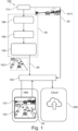
- Fig. 1 and Fig. 3 show, respectively, an object detecting system 100 for a vehicle 500, while a vehicle 500 having an object detecting system 100 with a user interface 150 is shown in Fig. 2 for carrying out a computer implemented method as schematically illustrated in Fig. 5 . Moreover, Fig. 3 shows a user interface
- the object detecting system 100 may comprise an image sensor 110, which may be designed to capture a first image or video scene 1511.
- the image sensor 110 may, for example, be a camera that may be provided in the vehicle and at least partially directed to the front of the camera, so that the camera may capture a live-viewing image or video scene of the road in front of the vehicle while travelling along a planned route.
- the object detecting system 100 may further comprise a user interface 150, which may comprise a touchscreen display that may allow an interactive communication between a user, such as a driver or an occupant of the vehicle, and a control and monitoring system of the vehicle.
- the user interface 150 may comprise a first frame 151, which may be configured to visualize or display the first image or video scene 1511 captured by and received from the image sensor 110, by following a step 20 (also shown in Fig. 5 ).
- the user interface 150 may further comprise a second frame 152, which may be arranged in parallel to the first frame 151.
- the second frame 152 may be arranged under or next to the first frame 151.
- the second frame 152 of the user interface 150 may be configured to visualize or display a second image or video scene 1521, which may be an animated image or video scene of the first image or video scene 1511, by following a step 40 (also as shown in Fig. 5 ).
- the object detecting system 100 may further comprise a perception module 180, which may comprise a perception model 185 that may be a neural network-based model. Based on the perception model 185, the perception module 180 may be configured to convert the first image or video scene 1511 to the second image or video scene 1521 via a converting unit 120 for generating an annotation prompt 155 of an object 800. The conversion from the first image or video scene 1511 to the second image or video scene 1521 may follow a converting step 30 (also shown in Fig. 5 ).
- Fig. 3 shows that the object 800 may be a pedestrian, an obstacle or a different traveling vehicle 500 on the road in front of the vehicle or downstream of the planning route of the vehicle 500.
- the object 800 may be detected by the image sensor and annotated in the first and/or second image or video scenes, so that a collision or an accident of the vehicle with the object may be prevented in advance.
- the display of the user interface 150 may be configured to allow the user to compare the first and second image or video scenes 1521, 1522, to identify a difference between the first and second image or video scenes 1521, 1522, by following a step 50 (also shown in Fig. 5 ), and to determine an adjusting event for triggering and/or modifying the annotation prompt 155.
- the user interface may allow the user recording the adjusting event by triggering and/or modifying the annotation prompt 155 of the object 800 in the first frame 151 and/or in the second frame 152.
- the first frame 151 may be arranged as the upper frame displaying the first image or video scene 1511 out of the camera sensor 110.
- the camera sensor 110 may reveal raw sensor data from the reality during the driving and transform the raw sensor data into the camera projected first image or video scene 1511.
- the second frame 152 may be arranged as the lower frame displaying the converted and animated second image or video scene 1521 that may reflect the environment outputted from the perception module 180 based on the first image or video scene 1511.
- the user interface 150 may be designed to be a gamified user interface and comprise a touchscreen display.
- the object 800 and/or the annotation prompt 155 of the object 800 corresponding to the adjusting event may be defined to be a ghost event in the gamified user interface, which may be configured to allow the user gaining predefined gaming points by determining and recording the adjusting event, in particular, by touching the touchscreen display at a respective location in the first frame 151 or in the second frame 152 to trigger the respective annotation prompt 155 of the object 800.
- Fig. 4a and Fig. 4b show, respectively, that the adjusting event may be an object missing event 161 or an object falsely detecting event 162.
- the object missing event 161 may be determined by the user as a false negative event, when the object 800, such as the pedestrian in the first image or video scene in the first frame 151, and the annotation prompt 155 of the object are missing in the animated second image or video scene in the second frame 152 by the conversion using the perception module 180.
- the object 800 captured in the first image or video scene 1511 may correspond to the object or the pedestrian on the road in front of the vehicle while driving in reality, the omitted or missing object in the animated second image or video scene may lead to a collision with the object, when the perception system or the perception module 180 fails to detect the presence of the object 800. In this case, as shown in Fig.
- the object in the first image or video scene or in the camera projected video may be detected and shown as a ghost object at a location in the first frame 151.
- the user may touch the second frame 152 of the touchscreen display of the user interface 150 at the respective location to record the object missing event 161.
- the user may trigger the annotation prompt 155 of the ghost object 800 in the second frame 152 as an infotainment screen frame.
- the gamified user interface 150 may be configured to allow the user gaining predefined gaming points as a reward for hunting the ghost object at the respective location in the second frame 152.
- the object falsely detecting event 162 may be determined by the user as a false positive event, when the object 800 or the pedestrian, which appears in the second image or video scene 1521 in the second frame 152, is not visualized in the first image or video scene 1511 in the first frame 151 and may not exist in the reality.
- the perception system or the perception module 180 of the vehicle 500 may falsely detect the object 800, as the user may see an object in the animated second image or video scene 1521 in the second frame 152 that does not exist in reality.
- the falsely detected object shown in the second frame 152 or the infotainment frame may lead to an unnecessary sharp braking during driving, resulting a discomfort or a rear-end collision.
- the falsely detected object in the second frame 152 may be shown as a ghost object at a location in the second frame 152.
- the user may touch the first frame 151 of the touchscreen display of the user interface 150 at the respective location to record the object falsely detecting event 162. Accordingly, the user may trigger the annotation prompt 155 of the object 800 in the first frame 151 at the respective location.
- the user may touch the second frame 152 as the infotainment screen frame of the touchscreen display and modify the annotation prompt 155 of the object 800.
- the gamified user interface 150 may be configured to allow the user gaining predefined gaming points as a reward for hunting the ghost objects at the respective location in the first frame 151.
- the object detecting system 100 may further comprise an evaluation unit that may be configured to generate and/or output a data set, based on the adjusting event recorded and/or the annotation prompt 155 of the object 800 triggered and/or modified by the user for modifying and/or training the perception model 185 of the perception module 180. Further, the evaluation unit may be configured to evaluate an accuracy rate of the data set for assessing the attentiveness of the user based on a function of an accuracy.
- the evaluation unit of the object detecting system 100 may generate the respective data set depending on the object missing or object falsely detecting event 161, 162.
- the respective data set may be analyzed by the perception module 180 for improving the accuracy and the efficiency of the perception model 185 of the object detecting system 100.
- the object detecting system 100 may further comprise a communication unit, which may be configured to transmit the data set, based on the adjusting event 161, 162 and/or the annotation prompt 155 of the object 800, and/or a location data set of the adjusting event to an external device 200, as shown in Fig. 1 .
- the external device 200 may be a mobile terminal, a server and/or a cloud system for a fleet that may comprise a plurality of vehicles 500.
- the object detecting system 100 may further comprise a position sensor that may be configured to detect or receive the location data set of the adjusting event 161, 162 while the vehicle traveling along the planned route on the road.
- the perception module 180 may be designed as part of a training module for a fleet that comprises a plurality of the vehicles 500, each of which may be provided with an object detecting system 100.
- the perception module 180 may comprise the perception model 185 as a neural network-based model, which may be performed in a matlab-based or non-matlab-based computer program.
- the communication unit for the fleet may be configured to a plurality of data sets generated by a plurality of users from a plurality of vehicles 500 of the fleet by means of the external device 200 such as the cloud system.
- the evaluation unit may be configured to evaluate a plurality of accuracy rates of the plurality of data sets and/or to assess the attentiveness of the plurality of users based on a function of an accuracy.
- the evaluation unit may be configured to modify and/or train the perception model 185 of the perception module 180 by weighing and prioritizing the plurality of data sets generated by the plurality of users from the plurality of the vehicles 500 of the fleet.
- the communication unit may further allow a vehicle-to-vehicle communication in the fleet.
- the user interface 150 may be designed to be gamified user interface
- the plurality of the users including drivers, occupants, developers, testers or professional data collectors, and game players may use the gamified user interface, for example, on an interactive onboard touchscreen display in the vehicle or on a connected smartphone, tablet or laptop to generate a big data analysis system with the plurality of the data sets and to train the perception module and the perception model which may follow machine learning algorithms.
- This may advantageously enable determining and recording as many as rare adjusting events from real-world driving and/or from the training module with artificially introduced object missing or object negatively detecting events 161, 162 with the generated plenty of data sets.
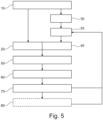
- Fig. 5 shows a flow chart illustrating a computer-implemented method for training and/or operating an object detecting system 100 for a vehicle 500.
- the method may start at step 10 where a first image or video scene 1511 may be captured, for example as a camera projected image or video scene, by means of an image sensor 110 of the vehicle 500.
- the first image or video scene 1511 may be visualized in a first frame 151 of a user interface.
- the first image or video scene 1511 may be converted to a second image or video scene 1521 for generating an annotation prompt 155 of the object 800 based on a perception model 185 of a perception module 180, and at step 40, the second image or video scene 1521, which may be an animated image or video scene of the first image or video scene 1511, and the annotation prompt 155 of the object 800 may be visualized in a second frame 152 of the user interface 150.
- an adjusting event may be determined by the user for triggering and/or modifying the annotation prompt 155 of the object 800 in the first image or video scene 1511 and/or in the second image or video scene 1521, after the user may identify, at step 50, a difference between the second image or video scene 1521 and the first image or video scene, which may be arranged in parallel to each other, in particular, one above or next to the other.
- the adjusting event may be recorded, at step 70, by triggering and/or modifying the annotation prompt 155 of the object 800 in the first frame 151 and/or the second frame 152 of the user interface 150 based on the adjusting event by the user.
- the step 60 of determining the adjusting event for triggering and/or modifying the annotation prompt 155 of the object 800 may comprise the step of determining that the annotation prompt 155 of the object may be missing or falsely generated in the second image or video scene 1521 by the user.
- the step 70 of recording the adjusting event may comprise the step of recording an object missing event 161, when the user compares the first and second image or video scenes 1511, 1521 and determines that the annotation prompt 155 of the object 800 is missing or not generated at a location in the second image or video scene 1521 after the conversion of the perception module 180 based on the perception model 185 of the perception module 80.
- the object missing event 161 is determined as a false negative event, the user may record the object missing event 161 by triggering the annotation prompt 155 of the object 800 in the second frame 152.
- the data set may be generated and outputted to the perception module 180 to modify and/or train the perception model 185.
- the step 70 of recording the adjusting event may comprise the step of recording an object falsely detecting event 162, when the user compares the first and second image or video scenes 1511, 1521 and determines that the annotation prompt 155 of the object 800 is erroneously annotated or falsely generated in the second image or video scene 1521, since the object 800 does not exist in the first image or video scene 1511 that may be a camera projected image or video scene of the reality.
- the object falsely detecting event 162 is determined as a false positive event, the user my record the object missing event 162 by triggering the annotation prompt 155 of the object 800 in the first frame 151 of the user interface 150.
- the user may modify or cancel the falsely annotated annotation prompt 155 of the object 800 in the second frame.
- the data set may be generated and outputted to the perception module 180 to modify and/or train the perception model 185.
- a data set may be generated and/or outputted to the perception module 180 based on the adjusting event recorded and/or the annotation prompt 155 of the object 800 triggered and/or modified by the user, so that the data set may be used further to modify and/or train the perception model 185 of the perception module 180 at step 35.
- the modified or trained perception model 185 may be applied for the step 30 of converting the first image or video scene 1511 to the second image or video scene 1521.
- the computer-implemented method may further comprise the step of transmitting the data set of the adjusting event 161, 162 and a location data set of the adjusting event to an external device 200 by means of a communication unit such as a connected mobile terminal, a server and/or a cloud system, so that the data set and the modified and/or trained perception model 185 may be communicated and shared within a fleet comprising a plurality of vehicles 500.
- a communication unit such as a connected mobile terminal, a server and/or a cloud system
- a computer program may be stored/distributed on a suitable medium such as an optical storage medium or a solid-state medium supplied together with or as part of other hardware, but may also be distributed in other forms, such as via the Internet or other wired or wireless telecommunication systems. Any reference signs in the claims should not be construed as limiting the scope of the claims.
Landscapes
- Engineering & Computer Science (AREA)
- Theoretical Computer Science (AREA)
- Physics & Mathematics (AREA)
- General Physics & Mathematics (AREA)
- Evolutionary Computation (AREA)
- Multimedia (AREA)
- Artificial Intelligence (AREA)
- Health & Medical Sciences (AREA)
- General Health & Medical Sciences (AREA)
- Data Mining & Analysis (AREA)
- Software Systems (AREA)
- Computing Systems (AREA)
- Computer Vision & Pattern Recognition (AREA)
- General Engineering & Computer Science (AREA)
- Life Sciences & Earth Sciences (AREA)
- Medical Informatics (AREA)
- Databases & Information Systems (AREA)
- Biomedical Technology (AREA)
- Biophysics (AREA)
- Computational Linguistics (AREA)
- Molecular Biology (AREA)
- Mathematical Physics (AREA)
- Bioinformatics & Cheminformatics (AREA)
- Bioinformatics & Computational Biology (AREA)
- Evolutionary Biology (AREA)
- Traffic Control Systems (AREA)
Abstract
The disclosure relates to a computer-implemented method for training and/or operating an object detecting system (100) for a vehicle (500) and an object detecting system (100) for a vehicle. The method comprises the steps of visualizing (20) a first image or video scene (1511) in a first frame (151) of a user interface (150), converting (30) the first image or video scene (1511) to a second image or video scene (1521) for generating an annotation prompt (155) of the object (800) based on a perception model (185) of a perception module (180), visualizing (40) the second image or video scene (1521) and/or the annotation prompt, determining (60) an adjusting event for triggering and/or modifying the annotation prompt (155), and recording (70) the adjusting event by triggering and/or modifying the annotation prompt in the first frame and/or the second frame by the user.
Description
- The present disclosure relates to a computer-implemented method for training and/or operating an object detecting system for a vehicle, an object detecting system for a vehicle in a fleet, a vehicle comprising an object detecting system and a training module for an object detecting system for a fleet.
- Autonomous vehicles are developed with object sensing techniques. The robustness and the reliability of such sensing techniques are of a great importance for such advance driver-assistance systems (ADAS) and automated driving Systems (ADS), since the functions of the ADAS and ADS systems may provide safety and protection by avoiding catastrophes such as notorious accidents while driving the vehicles.
- It is an objective of the present disclosure to provide an optimised object sensing system for a vehicle with high accuracy and efficiency and without oversensitivity.
- The problem is at least partially solved or alleviated by the subject matter of the independent claims of the present disclosure, wherein further examples are incorporated in the dependent claims.
- According to a first aspect, there is provided a computer-implemented method for training and/or operating an object detecting system for a vehicle. The computer implemented method comprises the following steps:
- visualizing, in a first frame of a user interface, a first image or video scene,
- converting the first image or video scene to a second image or video scene for generating an annotation prompt of the object based on a perception model of a perception module,
- visualizing, in a second frame of the user interface, the second image or video scene and/or the annotation prompt of the object,
- determining an adjusting event for triggering and/or modifying the annotation prompt of the object in the first image or video scene and/or in the second image or video scene, if a difference between the second image or video scene and the first image or video scene is identified by a user; and
- recording the adjusting event by triggering and/or modifying the annotation prompt of the object, based on the adjusting event, in the first frame and/or the second frame of the user interface by the user.
- The second image or video scene is an animated image or video scene of the first image or video scene. In other words, the second image or video scene may be the animation created image or video scene by converting the first image or video scene using the perception module. In contrast, the first image or video scene may be generated from raw data of a camera image or video.
- The computer-implemented method may also be used for monitoring the object detecting system, anomaly detection of the object detecting system and/or data collection of the object detecting system.
- The vehicle may be a fully or partially autonomous vehicle. Optionally, the vehicle may be an electric battery vehicle (BEV). The object may be a pedestrian, an obstacle or a different traveling vehicle on the road in front of the vehicle or downstream of the planning route of the vehicle. The object may be detected by the image sensor and annotated in the first and/or second image or video scenes, so that a collision or an accident of the vehicle with the object may be prevented in advance.
- For example, the adjusting event may start from a predefined few seconds, preferably 10 to 20 seconds, before the user touching the user interface for recording the adjusting event and end in a predefined few seconds, preferably 10 to 20 second after the user touching the user interface for recording the adjusting event.
- In an example, the computer-implemented method may further comprise the step of generating and/or outputting a data set, based on the adjusting event recorded and/or the annotation prompt of the object triggered and/or modified by the user, for modifying and/or training the perception model of the perception module.
- The perception model of the perception module may be a neural network-based model and follow machine learning algorithms, of which the outputs may be influenced by the data set. Further, the perception model may be designed to be an object determining model, by means of which the annotation prompt of the object may be determined and annotated in the animated second image or video scene based on the raw camera data of the first image or video scene captured from the reality of the driving.
- The perception system or the perception module of the object detecting system may be crucial for the static and dynamic accuracy and the sensitivity of the object detecting system of the vehicle, as the perception may be defined as the ability to process and understand information gained from the external environment from the data provided by multiple sensors of the vehicle. A reliable and robust object detecting system may be provided, when the user may continuously assist to optimize the perception model of the perception module, which may be arranged in the AD or ADAS software stack of the vehicle, by determining and recording a plurality of adjusting events or rare events in a training module or during the real-world driving. Such rare events may possibly occur from daily drives by the drivers or the AD/ADAS driving modes. Therefore, different autonomous driving components may form different approaches to collect data of the rare event, for example, mismatches from the fleet that may comprise multiple vehicles. The data generated in the collected rare events may thus be used to train the machine learning model of the perception module and/or reproduce the scenarios in a simulation environment for performing the verification and validation.
- The data set may be generated or recorded for a predefined time interval ranging from a few seconds prior to a time point where the touchscreen of the user interface is touched by the user to a few seconds after the time point.
- In an example, the user interface may be a gamified user interface. Alternatively or additionally, the user interface may comprise a touchscreen display of an infotainment system, which may be configured to allow an interactive communication between the vehicle, in particular a control system of the vehicle, and the user such as the driver or the occupant in the vehicle.
- In order to generate multiple data sets at various geographical locations, for example from the rare events or critical scenarios such as sharply breaking the vehicle or omitting a rare road obstacle, the user interface may be designed to be a game interface of a game, for example named as a ghost hunting game. The users including drivers, occupants, passengers, system developers and professional data collectors may be motivated to test, modify and train the perception model of the perception module, while operating the object detecting system and annotating data when monitoring the adjusting events. The adjusting events such as the object missing or falsely detecting events may be designed to be ghost events, and the missing or falsely detected objects may be designed to be the ghost objects. The gamified user interface may be designed to allow the game players gaining gaming points as a reward for determining and recording the ghost events and hunting the ghost objects at the respective locations in the first touchscreen frame and/or in the second touchscreen frame of the gamified user interface. In this way, the users may also be entertained by the game while detecting the critical scenarios for the object detection system.
- In an example, the step of determining the adjusting event for triggering and/or modifying the annotation prompt of the object may comprise the step of determining that the annotation prompt of the object is missing or falsely generated in the second image or video scene by the user.
- By converting the first image or video scene into the animated second image or video scene using the perception module, the object may be erroneously omitted or erroneously detected based on the pre-existing or current perception model.
- The object missing event may lead to an accident or a collision of the vehicle with the object. For example, due to the object missing event, the object detecting system of the vehicle may not be able to detect a pedestrian when riding a bicycle on the road downstream of the driving route of the vehicle. For example, due to the object missing event, the object detecting system of the vehicle may not be able to detect a white truck that is tipped over on the road downstream of the driving route of the vehicle, which may result in a collision accident.
- The object falsely detecting event may lead to an accident or a discomfort for the driver and the occupant, as the vehicle may be sharply braked during the driving when the object, which is not present in reality, is falsely detected. For example, due to the object falsely detecting event, the object detecting system may falsely determine the presence of a pedestrian which in the AD or ADAS mode, resulting in a false braking and a rear-end collision.
- In an example, the step of recording the adjusting event may comprise the step of recording an object missing event, when the user may determine that the annotation prompt of the object may be missing or not generated in the second image or video scene based on the perception model of the perception module.
- For example, the object missing event may be determined as the adjusting event or a false negative event, in case that the object to be detected in the first image or video scene in the first frame of the user interface may not be recognized by the perception model and the annotation prompt of the object may thus lack in the converted and animated second image or video scene in the second frame of the user interface.
- In an example, the computer-implemented method may further comprise the step of triggering, based on the recorded object missing event, the annotation prompt of the object by the user in the second frame of the user interface. Alternatively and additionally, the computer-implemented method may further comprise the step of generating and/or outputting the data set, based on the recorded object missing event, for modifying and/or training the perception model of the perception module.
- Once the object missing event may be determined by the user when comparing the first and the second image or video scenes, the user may record the object missing event by touching the touchscreen display, in particular by generating the annotation prompt of the object, which may exist in the first image or video scene in the first frame, at a respective position in the second image or video scene in the second frame.
- Further, the data set generated during the determining and recording of the object missing event may be collected and transmitted to the perception module for training the perception model and thereby improving the conversion accuracy of the perception module.
- In an example, the step of recording the adjusting event may comprise the step of recording an object falsely detecting event, when the user may determine that the annotation prompt of the object may be falsely generated in the second image or video scene based on the perception model of the perception module.
- By contrast to determining the object missing event, the object falsely detecting event may be determined as the adjusting event or a false positive event, in case that the object, which may not exist in the first image or video scene in the first frame of the user interface, may be detected and/or annotated with the annotation prompt in the animated second image or video scene in the second frame of the user interface using the perception module.
- In an example, the computer-implemented method may further comprise the following steps:
- triggering, based on the recorded object falsely detecting event, the annotation prompt of the object by the user in the first frame of the user interface,
- alternatively or additionally, modifying the annotation prompt of the object in the second frame of the user interface by the user based on the recorded object falsely detecting event,
- alternatively or additionally, generating and/or outputting the data set, based on the recorded object falsely detecting event, for modifying and/or training the perception model of the perception module.
- In an example, the first image or video scene may be captured by means of an image sensor of the vehicle.
- The image sensor may be a camera, in particular, a stereo camera. For example, the camera may be at least partially directed to the exterior or the road in front of the vehicle and configured to capture the road in front of the vehicle while travelling. As such, the first image or video scene may be a live-viewing image or video scene of the road in front of the vehicle.
- In an example, the computer-implemented method may further comprise the step of transmitting the data set, based on the adjusting event for modifying and/or training the perception model of the perception module, and/or a location data set of the adjusting event to an external device by means of a communication unit. The external device may be a mobile terminal, a server and/or a cloud system.
- The location data set may be detected and recorded by a position sensor at a location, where the adjusting event, namely the object missing event and/or the object falsely detecting event, may be determined and recorded by the user by triggering the annotation prompt of the object in the first frame and/or in the second frame via the touchscreen display of the user interface.
- The data set in combination with the location data set of the vehicle may be communicated from the vehicle to the cloud system for a fleet that may comprise a plurality of vehicles. As such, the data set in combination with the location data set may be used by the cloud system for modifying and/or training a centralized perception model for the fleet. Moreover, the cloud system may be designed to collect a plurality data sets in combination with a plurality of location data sets from the plurality of vehicles to training, optimizing and updating the perception model of the perception module for the fleet, continuously or at a predefined time interval. Alternatively and additionally, the plurality data sets in combination with the plurality of location data sets collected from the plurality of vehicles of the fleet may be received by the vehicle from the external device or the cloud system. Optionally, the updated perception model may be received by the vehicle from the cloud system via the communication unit for converting the first image or video scene to the second image or video scene and annotating the object with the annotation prompt, for example, if the object may be relevant for actuating a braking action of the vehicle or for predicting a possible collision.
- Further, there may be provided a computer program element for an object detecting system according to the present disclosure, which, when being executed by a processing element of a vehicle, is adapted to perform the method steps of the first aspect.
- The method may be at least partly computer-implemented, and may be implemented in software or in hardware, or in software and hardware. Further, the method may be carried out by computer program instructions running on means that provide data processing functions. The data processing means may be a suitable computing means, such as an electronic control module etc., which may also be a distributed computer system. The data processing means or the computer, respectively, may comprise one or more of a processor, a memory, a data interface, or the like.
- The computer-implemented method according to the present disclosure may advantageously scale as a result of the data collection of the rare events following the machine learning algorithms. The method according to the present disclosure may further enable the data collection of the rare scenarios in the complex reality, compared to the rule-trigged methods or shadow mode methods, without requiring certain conditions to be fulfilled. Further, the present method may potentially collect high-quality data with accurate annotations as the skills of the users may improve simultaneously for the training neural network model of the perception system.
- According to a second aspect, there is provided an object detecting system for a vehicle for carrying out the computer-implemented method according to the present disclosure. The object detecting system comprises a user interface and a perception module. The user interface comprises a first frame, which is configured to visualize a first image or video scene captured by an image sensor, and a second frame, which is arranged in parallel to the first frame.
- The perception module comprises a perception model which may be a neural network-based model. The perception module is configured to convert the first image or video scene to a second image or video scene for generating an annotation prompt of the object based on the perception model.
- For example, the perception model may be implemented in a matlab based model or a non-matlab based computer program.
- The second frame of the user interface is configured to visualize the second image or video scene and/or the annotation prompt of the object, which is an animated image or video scene of the first image or video scene.
- The user interface is configured to allow a user determining an adjusting event for triggering and/or modifying the annotation prompt of the object in the first image or video scene and/or in the second image or video scene by identifying a difference between the second image or video scene and the first image or video scene. Further, the user interface is configured to allow the user recording the adjusting event by triggering and/or modifying the annotation prompt of the object in the first frame and/or in the second frame based on the adjusting event.
- By converting the first image or video scene into the animated second image or video scene using the perception module, the object may be erroneously omitted or erroneously detected based on the pre-existing or current perception model. The adjusting event may be an object missing event or a negative false event, when the object in the first image or video scene in the first frame may be not present or annotated in the animated second image or video scene in the second frame after converting by the perception module. Alternatively, the adjusting event may be an object falsely detecting event or a negative positive event, when the object detected and annotated in the animated second image or video scene in the second frame may not exist in the first image or video scene in the first frame.
- In an example, the object detecting system may further comprise an evaluation unit, which may be configured to generate and/or output a data set, based on the adjusting event recorded and/or the annotation prompt of the object triggered and/or modified by the user for modifying and/or training the perception model of the perception module.
- Alternatively or additionally, the evaluation unit may be configured to evaluate an accuracy rate of the data set for assessing the attentiveness of the user based on a function of an accuracy.
- In an example, the object detecting system may further comprise a communication unit, which may be configured to transmit the data set, based on the adjusting event and/or the annotation prompt of the object, and/or a location data set of the adjusting event to an external device. The external device may be a mobile terminal, a server and/or a cloud system for a fleet, the fleet comprising a plurality of vehicles.
- According to a third aspect, there is provided a vehicle comprising an object detecting system according to the present disclosure for providing a driving safety system during an autonomous driving.
- Additionally, there may be provided the use of the object detecting system and/or the vehicle comprising the object detecting system according to the present disclosure for preventing a collision with a pedestrian, and/or for preventing the vehicle from sharply braking the vehicle in the autonomous driving mode and thereby protecting the driver and occupant in the vehicle.
- According to a fourth aspect, there is provided a training module for an object detecting system according to the present disclosure for a fleet that comprises a plurality of vehicles. The training module comprises a perception module, a communication unit and an evaluation unit. The perception module comprises a perception model that is a neural network-based model.
- The communication unit is configured to receive a plurality of data sets generated by plurality of users from the plurality of vehicles of the fleet by means of an external device, the external device is a mobile terminal, a server and/or a cloud system.
- Accordingly, the communication unit may be configured to allow a centralized big data analysis on the plurality of data sets for developing and training the perception model. Further, the communication unit may be configured to transmit the trained perception model to each individual vehicle of the fleet.
- The evaluation unit is configured to evaluate a plurality of accuracy rates of the plurality of data sets and/or to assess the attentiveness of the plurality of users based on a function of an accuracy. Additionally, the evaluation unit is configured to modify and/or train the perception model of the perception module by weighing and prioritizing the plurality of data sets generated by the plurality of users from the plurality of the vehicles of the fleet.
- When designed to be a gamified program, the training module may be actuated by the driver or the passenger when the driving may be deemed safe and when AD mode is active. Further, for training purpose, rare scenarios of the object missing or falsely detecting events may be introduced into the training module to entertain and attract the users. By assessing the accuracy of the generated data sets and the attentiveness of the users, the gamified training module may be designed to rate the data sets from the different users and prioritize the data sets with a higher accuracy.
- It should be noted that the above examples may be combined with each other irrespective of the aspect involved. Accordingly, the method may be combined with structural features and, likewise, the apparatus and the system may be combined with features described above with regard to the method.
- These and other aspects of the present disclosure will become apparent from and elucidated with reference to the examples described hereinafter.
- Examples of the disclosure will be described in the following with reference to the following drawings.
- Fig. 1
- shows schematically an example of an object detecting system according to the present disclosure.
- Fig. 2
- shows schematically an example of a vehicle comprising an object detecting system according to the present disclosure.
- Fig. 3
- shows schematically an example of a user interface of an object detecting system according to the present disclosure.
- Fig. 4a
- shows schematically an example of a user interface of an object detecting system according to the present disclosure.
- Fig. 4b
- shows schematically an example of a user interface of an object detecting system according to the present disclosure.
- Fig. 5
- shows schematically a flow chart illustrating a computer-implemented method for training and/or operating an object detecting system for a vehicle according to the present disclosure.
- The figures are merely schematic representations and serve only to illustrate examples of the disclosure. Identical or equivalent elements are in principle provided with the same reference signs.
-
Fig. 1 andFig. 3 show, respectively, anobject detecting system 100 for avehicle 500, while avehicle 500 having anobject detecting system 100 with auser interface 150 is shown inFig. 2 for carrying out a computer implemented method as schematically illustrated inFig. 5 . Moreover,Fig. 3 shows a user interface - In
Fig. 1 andFig. 3 , theobject detecting system 100 may comprise animage sensor 110, which may be designed to capture a first image orvideo scene 1511. Theimage sensor 110 may, for example, be a camera that may be provided in the vehicle and at least partially directed to the front of the camera, so that the camera may capture a live-viewing image or video scene of the road in front of the vehicle while travelling along a planned route. - As shown in
Fig. 1 andFig. 3 , theobject detecting system 100 may further comprise auser interface 150, which may comprise a touchscreen display that may allow an interactive communication between a user, such as a driver or an occupant of the vehicle, and a control and monitoring system of the vehicle. Theuser interface 150 may comprise afirst frame 151, which may be configured to visualize or display the first image orvideo scene 1511 captured by and received from theimage sensor 110, by following a step 20 (also shown inFig. 5 ). Theuser interface 150 may further comprise asecond frame 152, which may be arranged in parallel to thefirst frame 151. For example, thesecond frame 152 may be arranged under or next to thefirst frame 151. Thesecond frame 152 of theuser interface 150 may be configured to visualize or display a second image orvideo scene 1521, which may be an animated image or video scene of the first image orvideo scene 1511, by following a step 40 (also as shown inFig. 5 ). - In
Fig. 1 , in order to generate the animated second image orvideo scene 1521 corresponding to the first image orvideo scene 1511, theobject detecting system 100 may further comprise aperception module 180, which may comprise aperception model 185 that may be a neural network-based model. Based on theperception model 185, theperception module 180 may be configured to convert the first image orvideo scene 1511 to the second image orvideo scene 1521 via a convertingunit 120 for generating anannotation prompt 155 of anobject 800. The conversion from the first image orvideo scene 1511 to the second image orvideo scene 1521 may follow a converting step 30 (also shown inFig. 5 ). -
Fig. 3 shows that theobject 800 may be a pedestrian, an obstacle or adifferent traveling vehicle 500 on the road in front of the vehicle or downstream of the planning route of thevehicle 500. Theobject 800 may be detected by the image sensor and annotated in the first and/or second image or video scenes, so that a collision or an accident of the vehicle with the object may be prevented in advance. - The display of the
user interface 150 may be configured to allow the user to compare the first and second image orvideo scenes 1521, 1522, to identify a difference between the first and second image orvideo scenes 1521, 1522, by following a step 50 (also shown inFig. 5 ), and to determine an adjusting event for triggering and/or modifying theannotation prompt 155. - Further, based on the determined adjusting event, the user interface may allow the user recording the adjusting event by triggering and/or modifying the
annotation prompt 155 of theobject 800 in thefirst frame 151 and/or in thesecond frame 152. As shown inFig. 1 ,Fig. 3 ,Fig. 4a and Fig. 4b , thefirst frame 151 may be arranged as the upper frame displaying the first image orvideo scene 1511 out of thecamera sensor 110. Thecamera sensor 110 may reveal raw sensor data from the reality during the driving and transform the raw sensor data into the camera projected first image orvideo scene 1511. Thesecond frame 152 may be arranged as the lower frame displaying the converted and animated second image orvideo scene 1521 that may reflect the environment outputted from theperception module 180 based on the first image orvideo scene 1511. - The
user interface 150 may be designed to be a gamified user interface and comprise a touchscreen display. For example, theobject 800 and/or theannotation prompt 155 of theobject 800 corresponding to the adjusting event, may be defined to be a ghost event in the gamified user interface, which may be configured to allow the user gaining predefined gaming points by determining and recording the adjusting event, in particular, by touching the touchscreen display at a respective location in thefirst frame 151 or in thesecond frame 152 to trigger therespective annotation prompt 155 of theobject 800. -
Fig. 4a and Fig. 4b show, respectively, that the adjusting event may be anobject missing event 161 or an object falsely detectingevent 162. - In
Fig. 4a , theobject missing event 161 may be determined by the user as a false negative event, when theobject 800, such as the pedestrian in the first image or video scene in thefirst frame 151, and theannotation prompt 155 of the object are missing in the animated second image or video scene in thesecond frame 152 by the conversion using theperception module 180. As theobject 800 captured in the first image orvideo scene 1511 may correspond to the object or the pedestrian on the road in front of the vehicle while driving in reality, the omitted or missing object in the animated second image or video scene may lead to a collision with the object, when the perception system or theperception module 180 fails to detect the presence of theobject 800. In this case, as shown inFig. 4a , the object in the first image or video scene or in the camera projected video may be detected and shown as a ghost object at a location in thefirst frame 151. By identifying the missingghost object 800, the user may touch thesecond frame 152 of the touchscreen display of theuser interface 150 at the respective location to record theobject missing event 161. Accordingly, the user may trigger theannotation prompt 155 of theghost object 800 in thesecond frame 152 as an infotainment screen frame. For example, when theuser interface 150 is designed to be the gamified user interface, thegamified user interface 150 may be configured to allow the user gaining predefined gaming points as a reward for hunting the ghost object at the respective location in thesecond frame 152. - In
Fig. 4b , in contrast to theobject missing event 151 ofFig. 4a , the object falsely detectingevent 162 may be determined by the user as a false positive event, when theobject 800 or the pedestrian, which appears in the second image orvideo scene 1521 in thesecond frame 152, is not visualized in the first image orvideo scene 1511 in thefirst frame 151 and may not exist in the reality. In this case, the perception system or theperception module 180 of thevehicle 500 may falsely detect theobject 800, as the user may see an object in the animated second image orvideo scene 1521 in thesecond frame 152 that does not exist in reality. The falsely detected object shown in thesecond frame 152 or the infotainment frame may lead to an unnecessary sharp braking during driving, resulting a discomfort or a rear-end collision. In this case, as shown inFig. 4b , the falsely detected object in thesecond frame 152 may be shown as a ghost object at a location in thesecond frame 152. By identifying the object falsely detectingevent 162, the user may touch thefirst frame 151 of the touchscreen display of theuser interface 150 at the respective location to record the object falsely detectingevent 162. Accordingly, the user may trigger theannotation prompt 155 of theobject 800 in thefirst frame 151 at the respective location. Alternatively or additionally, the user may touch thesecond frame 152 as the infotainment screen frame of the touchscreen display and modify theannotation prompt 155 of theobject 800. For example, when theuser interface 150 is designed to be the gamified user interface, thegamified user interface 150 may be configured to allow the user gaining predefined gaming points as a reward for hunting the ghost objects at the respective location in thefirst frame 151. - The
object detecting system 100 may further comprise an evaluation unit that may be configured to generate and/or output a data set, based on the adjusting event recorded and/or theannotation prompt 155 of theobject 800 triggered and/or modified by the user for modifying and/or training theperception model 185 of theperception module 180. Further, the evaluation unit may be configured to evaluate an accuracy rate of the data set for assessing the attentiveness of the user based on a function of an accuracy. - By determining and recording the
object missing event 161 inFig. 4a and the object falsely detectingevent 162 inFig. 4b by means of theuser interface 151, the evaluation unit of theobject detecting system 100 may generate the respective data set depending on the object missing or object falsely detectingevent perception module 180 for improving the accuracy and the efficiency of theperception model 185 of theobject detecting system 100. - The
object detecting system 100 may further comprise a communication unit, which may be configured to transmit the data set, based on the adjustingevent annotation prompt 155 of theobject 800, and/or a location data set of the adjusting event to anexternal device 200, as shown inFig. 1 . Theexternal device 200 may be a mobile terminal, a server and/or a cloud system for a fleet that may comprise a plurality ofvehicles 500. Theobject detecting system 100 may further comprise a position sensor that may be configured to detect or receive the location data set of the adjustingevent - Moreover, the
perception module 180 may be designed as part of a training module for a fleet that comprises a plurality of thevehicles 500, each of which may be provided with anobject detecting system 100. Theperception module 180 may comprise theperception model 185 as a neural network-based model, which may be performed in a matlab-based or non-matlab-based computer program. - The communication unit for the fleet may be configured to a plurality of data sets generated by a plurality of users from a plurality of
vehicles 500 of the fleet by means of theexternal device 200 such as the cloud system. Accordingly, the evaluation unit may be configured to evaluate a plurality of accuracy rates of the plurality of data sets and/or to assess the attentiveness of the plurality of users based on a function of an accuracy. Additionally, the evaluation unit may be configured to modify and/or train theperception model 185 of theperception module 180 by weighing and prioritizing the plurality of data sets generated by the plurality of users from the plurality of thevehicles 500 of the fleet. Moreover, the communication unit may further allow a vehicle-to-vehicle communication in the fleet. - As the
user interface 150 may be designed to be gamified user interface, the plurality of the users including drivers, occupants, developers, testers or professional data collectors, and game players may use the gamified user interface, for example, on an interactive onboard touchscreen display in the vehicle or on a connected smartphone, tablet or laptop to generate a big data analysis system with the plurality of the data sets and to train the perception module and the perception model which may follow machine learning algorithms. This may advantageously enable determining and recording as many as rare adjusting events from real-world driving and/or from the training module with artificially introduced object missing or object negatively detectingevents -
Fig. 5 shows a flow chart illustrating a computer-implemented method for training and/or operating anobject detecting system 100 for avehicle 500. The method may start atstep 10 where a first image orvideo scene 1511 may be captured, for example as a camera projected image or video scene, by means of animage sensor 110 of thevehicle 500. - At a
subsequent step 20, the first image orvideo scene 1511 may be visualized in afirst frame 151 of a user interface. In parallel, atstep 30, the first image orvideo scene 1511 may be converted to a second image orvideo scene 1521 for generating anannotation prompt 155 of theobject 800 based on aperception model 185 of aperception module 180, and atstep 40, the second image orvideo scene 1521, which may be an animated image or video scene of the first image orvideo scene 1511, and theannotation prompt 155 of theobject 800 may be visualized in asecond frame 152 of theuser interface 150. - At
step 60, an adjusting event may be determined by the user for triggering and/or modifying theannotation prompt 155 of theobject 800 in the first image orvideo scene 1511 and/or in the second image orvideo scene 1521, after the user may identify, atstep 50, a difference between the second image orvideo scene 1521 and the first image or video scene, which may be arranged in parallel to each other, in particular, one above or next to the other. Once the adjusting event may be determined, the adjusting event may be recorded, atstep 70, by triggering and/or modifying theannotation prompt 155 of theobject 800 in thefirst frame 151 and/or thesecond frame 152 of theuser interface 150 based on the adjusting event by the user. - The
step 60 of determining the adjusting event for triggering and/or modifying theannotation prompt 155 of theobject 800 may comprise the step of determining that theannotation prompt 155 of the object may be missing or falsely generated in the second image orvideo scene 1521 by the user. - Accordingly, the
step 70 of recording the adjusting event may comprise the step of recording anobject missing event 161, when the user compares the first and second image orvideo scenes annotation prompt 155 of theobject 800 is missing or not generated at a location in the second image orvideo scene 1521 after the conversion of theperception module 180 based on theperception model 185 of theperception module 80. Once theobject missing event 161 is determined as a false negative event, the user may record theobject missing event 161 by triggering theannotation prompt 155 of theobject 800 in thesecond frame 152. Based on the recordedobject missing event 161, the data set may be generated and outputted to theperception module 180 to modify and/or train theperception model 185. - Alternatively, the
step 70 of recording the adjusting event may comprise the step of recording an object falsely detectingevent 162, when the user compares the first and second image orvideo scenes annotation prompt 155 of theobject 800 is erroneously annotated or falsely generated in the second image orvideo scene 1521, since theobject 800 does not exist in the first image orvideo scene 1511 that may be a camera projected image or video scene of the reality. Once the object falsely detectingevent 162 is determined as a false positive event, the user my record theobject missing event 162 by triggering theannotation prompt 155 of theobject 800 in thefirst frame 151 of theuser interface 150. Alternatively or additionally, the user may modify or cancel the falsely annotatedannotation prompt 155 of theobject 800 in the second frame. Based on the recorded object falsely detectingevent 162, the data set may be generated and outputted to theperception module 180 to modify and/or train theperception model 185. - Finally, at
step 80, a data set may be generated and/or outputted to theperception module 180 based on the adjusting event recorded and/or theannotation prompt 155 of theobject 800 triggered and/or modified by the user, so that the data set may be used further to modify and/or train theperception model 185 of theperception module 180 atstep 35. The modified or trainedperception model 185 may be applied for thestep 30 of converting the first image orvideo scene 1511 to the second image orvideo scene 1521. - The computer-implemented method may further comprise the step of transmitting the data set of the adjusting
event external device 200 by means of a communication unit such as a connected mobile terminal, a server and/or a cloud system, so that the data set and the modified and/or trainedperception model 185 may be communicated and shared within a fleet comprising a plurality ofvehicles 500. - Other variations to the disclosed examples can be understood and effected by those skilled in the art in practicing the claimed disclosure, from the study of the drawings, the disclosure, and the appended claims. In the claims the word "comprising" does not exclude other elements or steps and the indefinite article "a" or "an" does not exclude a plurality. A single processor or other unit may fulfill the functions of several items or steps recited in the claims. The mere fact that certain measures are recited in mutually different dependent claims does not indicate that a combination of these measures cannot be used to advantage. A computer program may be stored/distributed on a suitable medium such as an optical storage medium or a solid-state medium supplied together with or as part of other hardware, but may also be distributed in other forms, such as via the Internet or other wired or wireless telecommunication systems. Any reference signs in the claims should not be construed as limiting the scope of the claims.
-
- 100
- objective detecting system
- 110
- image sensor
- 120
- converting unit
- 150
- user interface
- 151
- first frame
- 1511
- first image or video scene
- 152
- second frame
- 1521
- second image or video scene
- 155
- annotation prompt
- 161
- object missing event
- 162
- object falsely detecting event
- 180
- perception module
- 185
- perception model
- 200
- external device
- 500
- vehicle
- 800
- object
- 10
- step of capturing first image or video scene
- 20
- step of visualizing first image or video scene
- 30
- step of converting first image or video scene to second image or video scene
- 35
- step of modifying and/or training perception model
- 40
- step of visualizing second image or video scene
- 50
- step of identifying a difference between first and second image or video scenes
- 60
- step of determining adjusting event
- 70
- step of recording adjusting event
- 80
- step of generating data set
Claims (15)
- A computer-implemented method for training and/or operating an object detecting system (100) for a vehicle (500), comprising:visualizing (20), in a first frame (151) of a user interface (150), a first image or video scene (1511);converting (30) the first image or video scene (1511) to a second image or video scene (1521) for generating an annotation prompt (155) of the object (800) based on a perception model (185) of a perception module (180);visualizing (40), in a second frame (152) of the user interface (150), the second image or video scene (1521) and/or the annotation prompt (155) of the object (800), the second image or video scene (1521) being an animated image or video scene of the first image or video scene (1511);determining (60) an adjusting event for triggering and/or modifying the annotation prompt (155) of the object (800) in the first image or video scene (1511) and/or in the second image or video scene (1521), by a user, by identifying (50) a difference between the second image or video scene (1521) and the first image or video scene (1511); andrecording (70) the adjusting event by triggering and/or modifying the annotation prompt (155) of the object (800), based on the adjusting event, in the first frame (151) and/or the second frame (152) of the user interface (150) by the user.
- The computer-implemented method according to claim 1, further comprising:generating and/or outputting (80) a data set, based on the adjusting event recorded and/or the annotation prompt (155) of the object (800) triggered and/or modified by the user, for modifying and/or training (35) the perception model (185) of the perception module (180);the perception model (185) of the perception module (180) being a neural network-based model.
- The computer-implemented method according to claim 1 or 2,the user interface (150) being a gamified user interface; and/orthe user interface (150) comprising a touchscreen display.
- The computer-implemented method according to one of the preceding claims,
determining the adjusting event for triggering and/or modifying the annotation prompt (155) of the object (800) comprising the step of determining that the annotation prompt (155) of the object (800) is missing or falsely generated in the second image or video scene (1521) by the user. - The computer-implemented method according to one of the preceding claims,
recording the adjusting event comprising the step of recording an object missing event (161), when the user determines that the annotation prompt (155) of the object (800) is missing in the second image or video scene (1521) based on the perception model (185) of the perception module (180). - The computer-implemented method according to claim 5, further comprising:triggering, based on the recorded object missing event (161), the annotation prompt (155) of the object by the user in the second frame (152) of the user interface (150); and/orgenerating and/or outputting the data set, based on the recorded object missing event (161), for modifying and/or training the perception model (185) of the perception module (180).
- The computer-implemented method according to one of the claims 1 to 4,
recording the adjusting event comprising the step of recording an object falsely detecting event (162), when the user determines that the annotation prompt (155) of the object (800) is falsely generated in the second image or video scene (1521) based on the perception model (185) of the perception module (180). - The computer-implemented method according to claim 7, further comprising:triggering, based on the recorded object falsely detecting event (162), the annotation prompt (155) of the object (800) by the user in the first frame (151) of the user interface (150); and/ormodifying, based on the recorded object falsely detecting event (162), the annotation prompt (155) of the object (800) in the second frame (152) of the user interface (150) by the user; and/orgenerating and/or outputting the data set, based on the recorded object falsely detecting event (162), for modifying and/or training the perception model (185) of the perception module (180).
- The computer-implemented method according to one of the preceding claims,
the first image or video scene (1511) being captured by means of an image sensor (110) of the vehicle (500). - The computer-implemented method according to one of the preceding claims, further comprising:transmitting the data set, based on the adjusting event for modifying and/or training the perception model (185) of the perception module (180), and/or a location data set of the adjusting event to an external device (200) by means of a communication unit;the external device (200) being a mobile terminal, a server and/or a cloud system.
- An object detecting system (100) for a vehicle (500) for carrying out the computer-implemented method according to one of the claims 1 to 10, comprising:a user interface (150) comprisinga first frame (151), the first frame (151) being configured to visualize a first image or video scene (1511) captured by an image sensor (110), anda second frame (152), arranged in parallel to the first frame (151); anda perception module (180), the perception module (180) comprising a perception model (185), the perception model (185) being a neural network-based model;the perception module (180) being configured to convert the first image or video scene (1511) to a second image or video scene (1521) for generating an annotation prompt (155) of the object (800) based on the perception model (185);the second frame (152) being configured to visualize the second image or video scene (1521) and/or the annotation prompt (155) of the object (800), the second image or video scene (1521) being an animated image or video scene of the first image or video scene (1511);the user interface (150) being configured to allow a user determining an adjusting event for triggering and/or modifying the annotation prompt (155) of the object (800) in the first image or video scene (1511) and/or in the second image or video scene (1521) by identifying a difference between the second image or video scene (1521) and the first image or video scene (1511); andthe user interface (150) being configured to allow the user recording the adjusting event by triggering and/or modifying the annotation prompt (155) of the object (800) in the first frame (151) and/or in the second frame (152) based on the adjusting event.
- The object detecting system (100) according to claim 11, further comprising:an evaluation unit,the evaluation unit being configured to generate and/or output a data set, based on the adjusting event recorded and/or the annotation prompt (155) of the object (800) triggered and/or modified by the user for modifying and/or training the perception model (185) of the perception module (180); and/orthe evaluation unit being configured to evaluate an accuracy rate of the data set for assessing the attentiveness of the user based on a function of an accuracy.
- The object detecting system (100) according to claim 11 or 12, further comprising:a communication unit;the communication unit being configured to transmit the data set, based on the adjusting event and/or the annotation prompt (155) of the object (800), and/or a location data set of the adjusting event to an external device (200);the external device (200) being a mobile terminal, a server and/or a cloud system for a fleet, the fleet comprising a plurality of vehicles (500).
- A vehicle (500) comprising an object detecting system (100) according to one of the claims 11 to 13 for providing a driving safety system during autonomous driving.
- A training module for an object detecting system (100) according to one of the claims 11 to 13 for a fleet, the fleet comprising a plurality of vehicles (500), comprising:a perception module (180), the perception module (180) comprising a perception model (185), the perception model (185) being a neural network-based model;a communication unit, andan evaluation unit;the communication unit being configured to receive a plurality of data sets generated by a plurality of users from the plurality of vehicles (500) of the fleet by means of an external device (200), the external device (200) being a mobile terminal, a server and/or a cloud system;the evaluation unit being configured to evaluate a plurality of accuracy rates of the plurality of data sets and/or to assess the attentiveness of the plurality of users based on a function of an accuracy; andthe evaluation unit being configured to modify and/or train the perception model (185) of the perception module (180) by weighing and prioritizing the plurality of data sets generated by the plurality of users from the plurality of the vehicles (500) of the fleet.
Priority Applications (1)
| Application Number | Priority Date | Filing Date | Title |
|---|---|---|---|
| EP23153081.7A EP4407482A1 (en) | 2023-01-24 | 2023-01-24 | Training and operating an object detecting system for a vehicle |
Applications Claiming Priority (1)
| Application Number | Priority Date | Filing Date | Title |
|---|---|---|---|
| EP23153081.7A EP4407482A1 (en) | 2023-01-24 | 2023-01-24 | Training and operating an object detecting system for a vehicle |
Publications (1)
| Publication Number | Publication Date |
|---|---|
| EP4407482A1 true EP4407482A1 (en) | 2024-07-31 |
Family
ID=85076032
Family Applications (1)
| Application Number | Title | Priority Date | Filing Date |
|---|---|---|---|
| EP23153081.7A Pending EP4407482A1 (en) | 2023-01-24 | 2023-01-24 | Training and operating an object detecting system for a vehicle |
Country Status (1)
| Country | Link |
|---|---|
| EP (1) | EP4407482A1 (en) |
Citations (4)
| Publication number | Priority date | Publication date | Assignee | Title |
|---|---|---|---|---|
| US20190228262A1 (en) * | 2019-03-30 | 2019-07-25 | Intel Corporation | Technologies for labeling and validating human-machine interface high definition-map data |
| US10963734B1 (en) * | 2018-10-19 | 2021-03-30 | Waymo Llc | Perception visualization tool |
| US20220277193A1 (en) * | 2021-02-26 | 2022-09-01 | Nvidia Corporation | Ground truth data generation for deep neural network perception in autonomous driving applications |
| US20220284666A1 (en) * | 2019-07-19 | 2022-09-08 | Five Al Limited | Structure annotation |
-
2023
- 2023-01-24 EP EP23153081.7A patent/EP4407482A1/en active Pending
Patent Citations (4)
| Publication number | Priority date | Publication date | Assignee | Title |
|---|---|---|---|---|
| US10963734B1 (en) * | 2018-10-19 | 2021-03-30 | Waymo Llc | Perception visualization tool |
| US20190228262A1 (en) * | 2019-03-30 | 2019-07-25 | Intel Corporation | Technologies for labeling and validating human-machine interface high definition-map data |
| US20220284666A1 (en) * | 2019-07-19 | 2022-09-08 | Five Al Limited | Structure annotation |
| US20220277193A1 (en) * | 2021-02-26 | 2022-09-01 | Nvidia Corporation | Ground truth data generation for deep neural network perception in autonomous driving applications |
Similar Documents
| Publication | Publication Date | Title |
|---|---|---|
| US10817751B2 (en) | Learning data creation method, learning method, risk prediction method, learning data creation device, learning device, risk prediction device, and recording medium | |
| US9990182B2 (en) | Computer platform for development and deployment of sensor-driven vehicle telemetry applications and services | |
| JP2020524632A (en) | System and method for obtaining occupant feedback in response to an autonomous vehicle driving event | |
| CN109190488B (en) | Front vehicle door opening detection method and device based on deep learning YOLOv3 algorithm | |
| JPWO2020022042A1 (en) | Deterioration diagnosis device, deterioration diagnosis system, deterioration diagnosis method, program | |
| US11455835B2 (en) | Information processing apparatus and information processing method | |
| WO2022025244A1 (en) | Vehicle accident prediction system, vehicle accident prediction method, vehicle accident prediction program, and trained model generation system | |
| US11881065B2 (en) | Information recording device, information recording method, and program for recording information | |
| CN113962107A (en) | Method and device for simulating driving road section, electronic equipment and storage medium | |
| CN110544312A (en) | Video display method and device in virtual scene, electronic equipment and storage device | |
| WO2024087887A1 (en) | Reckless driving behavior marking method, vehicle, cloud server, and storage medium | |
| CN118376420A (en) | Testing method and system for autonomous driving vehicles | |
| US20240338770A1 (en) | Information processing device, information processing method, server device, vehicle device, and information processing program | |
| EP3786854A1 (en) | Methods and systems for determining driving behavior | |
| EP4407482A1 (en) | Training and operating an object detecting system for a vehicle | |
| CN110892446A (en) | Analytical apparatus, analytical method and program | |
| US11887386B1 (en) | Utilizing an intelligent in-cabin media capture device in conjunction with a transportation matching system | |
| AU2024278728A1 (en) | Vehicle early warning method and apparatus, device, storage medium, and product | |
| CN113628360B (en) | Data acquisition method and system | |
| CN117807263A (en) | Vehicle data processing methods, devices, media, equipment and vehicles | |
| CN114973450A (en) | Driving evaluation device and driving evaluation method | |
| CN112669612B (en) | Image recording and playback method, device and computer system | |
| CN115688254A (en) | Automatic driving risk prediction method and device, storage medium and electronic equipment | |
| KR20240054743A (en) | Apparatus for testing a multimedia device, and method thereof | |
| JP2025076747A (en) | Information providing device and information providing method |
Legal Events
| Date | Code | Title | Description |
|---|---|---|---|
| PUAI | Public reference made under article 153(3) epc to a published international application that has entered the european phase |
Free format text: ORIGINAL CODE: 0009012 |
|
| STAA | Information on the status of an ep patent application or granted ep patent |
Free format text: STATUS: REQUEST FOR EXAMINATION WAS MADE |
|
| 17P | Request for examination filed |
Effective date: 20231213 |
|
| AK | Designated contracting states |
Kind code of ref document: A1 Designated state(s): AL AT BE BG CH CY CZ DE DK EE ES FI FR GB GR HR HU IE IS IT LI LT LU LV MC ME MK MT NL NO PL PT RO RS SE SI SK SM TR |