EP4407404A1 - Pedal assembly for a vehicle, drive-by-wire system for a vehicle, and vehicle - Google Patents
Pedal assembly for a vehicle, drive-by-wire system for a vehicle, and vehicle Download PDFInfo
- Publication number
- EP4407404A1 EP4407404A1 EP23153766.3A EP23153766A EP4407404A1 EP 4407404 A1 EP4407404 A1 EP 4407404A1 EP 23153766 A EP23153766 A EP 23153766A EP 4407404 A1 EP4407404 A1 EP 4407404A1
- Authority
- EP
- European Patent Office
- Prior art keywords
- pedal assembly
- actuation rod
- vehicle
- rod
- guide part
- Prior art date
- Legal status (The legal status is an assumption and is not a legal conclusion. Google has not performed a legal analysis and makes no representation as to the accuracy of the status listed.)
- Pending
Links
Images





Classifications
-
- B—PERFORMING OPERATIONS; TRANSPORTING
- B60—VEHICLES IN GENERAL
- B60T—VEHICLE BRAKE CONTROL SYSTEMS OR PARTS THEREOF; BRAKE CONTROL SYSTEMS OR PARTS THEREOF, IN GENERAL; ARRANGEMENT OF BRAKING ELEMENTS ON VEHICLES IN GENERAL; PORTABLE DEVICES FOR PREVENTING UNWANTED MOVEMENT OF VEHICLES; VEHICLE MODIFICATIONS TO FACILITATE COOLING OF BRAKES
- B60T7/00—Brake-action initiating means
- B60T7/02—Brake-action initiating means for personal initiation
- B60T7/04—Brake-action initiating means for personal initiation foot actuated
- B60T7/06—Disposition of pedal
-
- B—PERFORMING OPERATIONS; TRANSPORTING
- B60—VEHICLES IN GENERAL
- B60T—VEHICLE BRAKE CONTROL SYSTEMS OR PARTS THEREOF; BRAKE CONTROL SYSTEMS OR PARTS THEREOF, IN GENERAL; ARRANGEMENT OF BRAKING ELEMENTS ON VEHICLES IN GENERAL; PORTABLE DEVICES FOR PREVENTING UNWANTED MOVEMENT OF VEHICLES; VEHICLE MODIFICATIONS TO FACILITATE COOLING OF BRAKES
- B60T7/00—Brake-action initiating means
- B60T7/02—Brake-action initiating means for personal initiation
- B60T7/04—Brake-action initiating means for personal initiation foot actuated
- B60T7/042—Brake-action initiating means for personal initiation foot actuated by electrical means, e.g. using travel or force sensors
-
- G—PHYSICS
- G05—CONTROLLING; REGULATING
- G05G—CONTROL DEVICES OR SYSTEMS INSOFAR AS CHARACTERISED BY MECHANICAL FEATURES ONLY
- G05G1/00—Controlling members, e.g. knobs or handles; Assemblies or arrangements thereof; Indicating position of controlling members
- G05G1/30—Controlling members actuated by foot
- G05G1/42—Controlling members actuated by foot non-pivoting, e.g. sliding
-
- G—PHYSICS
- G05—CONTROLLING; REGULATING
- G05G—CONTROL DEVICES OR SYSTEMS INSOFAR AS CHARACTERISED BY MECHANICAL FEATURES ONLY
- G05G1/00—Controlling members, e.g. knobs or handles; Assemblies or arrangements thereof; Indicating position of controlling members
- G05G1/30—Controlling members actuated by foot
- G05G1/32—Controlling members actuated by foot with means to prevent injury
- G05G1/327—Controlling members actuated by foot with means to prevent injury means disconnecting the pedal from its hinge or support, e.g. by breaking or bending the support
-
- G—PHYSICS
- G05—CONTROLLING; REGULATING
- G05G—CONTROL DEVICES OR SYSTEMS INSOFAR AS CHARACTERISED BY MECHANICAL FEATURES ONLY
- G05G1/00—Controlling members, e.g. knobs or handles; Assemblies or arrangements thereof; Indicating position of controlling members
- G05G1/30—Controlling members actuated by foot
- G05G1/38—Controlling members actuated by foot comprising means to continuously detect pedal position
-
- G—PHYSICS
- G05—CONTROLLING; REGULATING
- G05G—CONTROL DEVICES OR SYSTEMS INSOFAR AS CHARACTERISED BY MECHANICAL FEATURES ONLY
- G05G1/00—Controlling members, e.g. knobs or handles; Assemblies or arrangements thereof; Indicating position of controlling members
- G05G1/30—Controlling members actuated by foot
- G05G1/40—Controlling members actuated by foot adjustable
-
- G—PHYSICS
- G05—CONTROLLING; REGULATING
- G05G—CONTROL DEVICES OR SYSTEMS INSOFAR AS CHARACTERISED BY MECHANICAL FEATURES ONLY
- G05G1/00—Controlling members, e.g. knobs or handles; Assemblies or arrangements thereof; Indicating position of controlling members
- G05G1/30—Controlling members actuated by foot
- G05G1/46—Means, e.g. links, for connecting the pedal to the controlled unit
-
- G—PHYSICS
- G05—CONTROLLING; REGULATING
- G05G—CONTROL DEVICES OR SYSTEMS INSOFAR AS CHARACTERISED BY MECHANICAL FEATURES ONLY
- G05G25/00—Other details or appurtenances of control mechanisms, e.g. supporting intermediate members elastically
- G05G25/04—Sealing against entry of dust, weather or the like
-
- G—PHYSICS
- G05—CONTROLLING; REGULATING
- G05G—CONTROL DEVICES OR SYSTEMS INSOFAR AS CHARACTERISED BY MECHANICAL FEATURES ONLY
- G05G5/00—Means for preventing, limiting or returning the movements of parts of a control mechanism, e.g. locking controlling member
- G05G5/05—Means for returning or tending to return controlling members to an inoperative or neutral position, e.g. by providing return springs or resilient end-stops
Definitions
- the present disclosure relates to a pedal assembly for a vehicle.
- the present disclosure also is directed to a drive-by-wire system for a vehicle.
- the present disclosure relates to a vehicle comprising such a pedal assembly and/or such a drive-by-wire system.
- a pedal assembly is one of the standard means being used by the human driver for operating the vehicle.
- the pedal assembly is for example a brake pedal assembly.
- the human driver can operate the vehicle's brakes by manipulating the brake pedal assembly.
- the pedal assembly may be an accelerator pedal assembly.
- the human driver can adjust an acceleration of the vehicle by manipulating the accelerator pedal assembly.
- the pedal assembly can also be a drive pedal assembly.
- a drive pedal assembly may be operated in order to adjust an acceleration of the vehicle.
- the drive pedal assembly offers the same functionality as an accelerator pedal assembly.
- the vehicle may also be decelerated.
- the drive pedal assembly additionally may offer a functionality which is otherwise provided by a brake pedal assembly.
- the pedal assembly may be mechanically coupled to the components of the vehicle being configured to provide the functionality being controlled by the operation of the pedal assembly.
- the pedal assembly may be mechanically connected to a brake system of the vehicle or to an engine of the vehicle.
- the pedal assembly is used as a part of a drive-by-wire system, the pedal assembly and the components of the vehicle being configured to provide the functionality being controlled by the operation of the pedal assembly are only coupled by electric means, e.g. electric wires.
- the pedal assembly is not mechanically coupled to the components of the vehicle being configured to provide the functionality being controlled by the operation of the pedal assembly.
- pedal assembly It is an objective of the present disclosure to improve known pedal assemblies. This is especially the case for pedal assemblies being used in drive-by-wire systems.
- the pedal assembly shall be structurally simple and compact.
- a pedal assembly for a vehicle.
- the pedal assembly comprises a mounting bracket having a mounting interface for mechanically attaching the pedal assembly to a structural part of the vehicle.
- the pedal assembly comprises a guide part being fixedly connected to the mounting bracket and comprising a channel extending linearly along a channel axis.
- the pedal assembly comprises an actuation rod extending along a rod axis and having a first end comprising or being coupled to a pushing surface. At least a portion of the actuation rod is located inside the channel.
- the rod axis and the channel axis are parallel and the pushing surface is configured to be contacted by a human foot for operating the pedal assembly.
- the pedal assembly comprises a sensor assembly being configured to detect an actuation of the actuation rod along the rod axis.
- the pedal assembly may be mechanically attached to the structural part of the vehicle in a simple and reliable manner.
- the mounting bracket may be configured to be mechanically attached to a floor component of the vehicle or a dashboard carrier component of the vehicle.
- the actuation rod having at least a portion thereof, e.g. its second end, located inside the linearly extending channel and the guide part are structurally simple. These parts offer a simple and compact actuation mechanism of the pedal assembly.
- the actuation rod and the guide part may be movable with respect to one another along the rod axis and the channel axis only.
- the actuation rod may be moved along a linear trajectory when operating the pedal assembly.
- the channel and the guide part as a whole guide this movement.
- the actuation rod may be fixedly connected to the guide part such that a relative movement of the actuation rod with respect to the guide part is not possible.
- the sensor assembly may detect an actuation of the actuation rod along the rod axis. This means that, using the sensor assembly, one may detect whether a user of the pedal assembly pushes the actuation rod via the pushing surface or not. At the same time a pushing intensity may be detected.
- the detection result of the sensor assembly may be used as a control input for a drive-by wire system.
- the pedal assembly is structurally simple. It comprises only comparatively few parts. Additionally, the pedal assembly is very compact.
- the basic idea underlying the present disclosure is to provide a pedal assembly, wherein the part of the pedal assembly that is actuated by a user of the pedal assembly, in the present disclosure the actuation rod, either perform a purely linear movement with respect to the part of the pedal assembly being fixedly arranged on the vehicle structure or no movement at all.
- the part being fixedly arranged on the vehicle structure is the guide part.
- the pedal assembly according to the present disclosure is structurally simple and compact.
- the channel is to be understood as an elongated volume having a length being at least three times the diameter. In an alternative, a length of the channel is at least five times the diameter.
- a channel can reliably guide the actuation rod when being actuated along the rod axis. In a case in which the actuation rod is not movable, the channel ensures that a reliable sensor signal is produced.
- the pushing surface is the surface of the pedal assembly on which a user of the pedal assembly presses his or her foot in order to operate the pedal assembly.
- the actuation rod comprises the pushing surface.
- the actuation rod and the pushing surface are formed integrally.
- the actuation rod may comprise a plate-shaped portion at its first end.
- the pushing surface may be an end face of the plate-shaped portion.
- the pushing surface may simply be an end face of the actuation rod's first end.
- the actuation rod is coupled to the pushing surface. This means that the pushing surface is provided on a part being separate from the actuation rod. Such a part may be called a thrust piece.
- This part is connected to the first end of the actuation rod.
- the part may be plate-shaped.
- the part may be connected to the first end of the actuation rod by any suitable means.
- the part is connected to the first end of the actuation rod via a clip.
- the part is glued or screwed to the first end of the actuation rod.
- the mounting bracket and the guide part may be provided as parts being separate from one another which are connected by an appropriate means when forming the pedal assembly.
- the mounting bracket and the guide part may for example be connected by one or more welding seams, by one or more screws or by one or more clips.
- the mounting bracket and the guide part may be formed as a single integral part. This means that the mounting bracket is formed as one portion of this single integral part and the guide part is formed as another portion of the same single integral part.
- the pedal assembly is a brake pedal assembly.
- the detection result of the sensor assembly may be used as a control input for a brake system of the vehicle.
- a pedal assembly is structurally simple and very compact.
- the guide part comprises a support element.
- the support element is arranged in the channel.
- the actuation rod is axially supported on the support element. It is noted that the support element may be arranged at an end of the channel or at an intermediate position, i.e. between the ends of the channel.
- the support of the actuation rod on the support element may be direct, i.e. the actuation rod may directly contact the support element, or indirect, i.e. the actuation rod is supported on the support element via one or more intermediate parts. Providing such a support element is a simple and reliable way to support the actuation rod.
- the support element is for example disc-shaped. Such a support element is compact.
- the support element comprises an opening and the actuation rod extends through the opening.
- the portion of the actuation rod extending through the opening may have a reduced diameter with respect to the remaining portions of the actuation rod.
- an abutment surface defining an extreme position of the actuation rod may be provided on both sides of the support element.
- both sides of the support element may be used to limit a range of motion of the actuation rod along the rod axis.
- the support element comprises at least one predetermined breaking zone.
- a predetermined breaking zone is defined as a zone of the support element offering a predetermined mechanical resistance or mechanical stability being lower than the mechanical resistance or mechanical stability of the adjacent parts. This has the effect that in a situation in which a very high force is applied on the actuation rod, the predetermined breaking zone will be mechanically deformed or mechanically broken whereas the remaining parts of the pedal assembly remain mechanically intact. This is helpful in a situation in which the vehicle comprising the pedal assembly is involved in an accident or a crash.
- the predetermined breaking zone will be mechanically deformed or mechanically broken such that a range of movement of the actuation rod is increased. Consequently, in such a situation, more room may be offered for the feet of the user of the pedal assembly. This increases crash safety for the user.
- the predetermined breaking zone comprises a plurality of slots. This means that the predetermined breaking zone is mechanically weakened by the plurality of slots. Using such slots, a mechanical resistance or mechanical stability may be adjusted in a precise and simple manner. Beyond that, a support element comprising a plurality of slots may be manufactured in the simple and cost-efficient manner.
- the pedal assembly further comprises a biasing element biasing the actuation rod into an unactuated position.
- a biasing element biasing the actuation rod into an unactuated position.
- a first effect relates to the fact that, due to the biasing element, the actuation rod always assumes the unactuated position, if no operational force acts thereon. Thus, the actuation rod always assumes a defined position such that the pedal assembly may be operated in a reliable manner.
- the second effect relates to the fact that the biasing element may provide a counterforce when being compressed during operation of the pedal assembly. This counterforce helps the user of the pedal assembly to precisely operate the pedal assembly.
- the biasing element comprises a spring element.
- the spring element may comprise a wound coil spring and/or an elastomeric spring element.
- the biasing element is supported on the support element.
- the biasing element is mechanically arranged between the actuation rod and the support element.
- the rod may be supported on the support element via the biasing element.
- the actuation rod comprises an abutment element being configured to abut against the guide part in an unactuated position of the actuation rod.
- the abutment element of the actuation rod may abut against the support element of the guide part. Consequently, the actuation rod may assume a well-defined position when being unactuated.
- the sensor assembly comprises a travel sensor being configured to detect a displacement of the actuation rod. Additionally or alternatively, the sensor assembly comprises a force sensor being configured to detect a force being applied to the actuation rod. Both the travel sensor and the force sensor allow to reliably detect an actuation of the pedal assembly, more precisely the actuation rod. Thus a system which is operated using the pedal assembly may be controlled in a precise manner. It is noted that the use of a travel sensor implies that the actuation rod moves relative to the guide part when being actuated. This is in contrast to the use of a force sensor which may be used in combination with a configuration in which the actuation rod may move relative to the guide part and also in combination with a configuration in which the actuation rod is not movable with respect to the guide part.
- the pedal assembly further comprises a sealing means being connected to the actuation rod and the guide part or the mounting bracket such that a contact region between the actuation rod and the guide part is protected against environmental influences.
- the sealing means may be effective in two directions. This means that influences resulting from a passenger compartment of the vehicle are not affecting the contact region between the actuation rod and the guide part. This especially applies to dirt and humidity which may be present in the passenger compartment.
- the sealing means has the effect that influences from the interior of the pedal assembly and/or parts to which it is connected cannot reach the passenger compartment. This especially relates to dirt and lubrication means.
- the sealing means is sleeve-shaped and extends around a circumference of the actuation rod and the guide part. Consequently, the sealing means protects the contact region between the actuation rod and the gate part from all sides. In other words, the sealing effect is highly reliable.
- the sleeve-shaped sealing means may be a sealing bellow.
- the reliability of the sealing effect is not affected by a relative movement between the actuation rod and the guide part.
- the pedal assembly further comprises a retraction actuator being coupled to the guide part or the mounting bracket and being configured to selectively move the actuation rod towards an interior of the channel.
- the retraction actuator may be configured to move the actuation rod from an unactuated position into a retracted position wherein in the retracted position a manipulation of the actuation rod by a user's foot may not be possible anymore.
- the retraction actuator is very useful if the pedal assembly is used in a vehicle being able to drive in a fully or partially autonomous mode, wherein in the fully or partially autonomous drive mode a use of the pedal assembly is not required. If, in such a situation, the actuation rod is moved further into the channel, the pushing surface is moved away from a user's foot. This means that more space is provided for the user's foot in case the pedal assembly is not needed. Altogether, user comfort is enhanced.
- a drive-by-wire system for a vehicle comprising a pedal assembly according to the present disclosure.
- the pedal assembly is a brake pedal assembly
- the drive-by-wire system is a brake-by-wire system. Due to the fact that the pedal assembly is structurally simple and compact, also the drive-by-wire system is structurally simple and compact. Beyond that, all the effects and advantages that have been mentioned in connection with the pedal assembly according to the present disclosure also apply to the drive-by-wire system according to the present disclosure and vice versa.
- a vehicle comprising a drive by-wire system according to the present disclosure and/or a pedal assembly according to the present disclosure.
- the pedal assembly and/or the drive-by-wire system is compact, the pedal assembly and/or the drive-by-wire system requires comparatively little space in the vehicle. This characteristic may be used to design the vehicle in a compact manner. Additionally or alternatively, this allows the vehicle to be designed in a manner that offers a comparatively large space to its users. Beyond that, all the effects and advantages that have been mentioned in connection with the pedal assembly and/or the drive-by-wire system also apply to the vehicle and vice versa.
- Figure 1 shows a vehicle 10.
- the vehicle 10 is a battery electric vehicle.
- the vehicle comprises a drive-by-wire system 12 which in the present example is a brake-by-wire system 14.
- the brake-by-wire system 14 comprises a brake actuator 16 for each of the vehicle's wheels, a pedal assembly 18 and a control unit 20.
- the pedal assembly 18 may be called a brake pedal assembly.
- the pedal assembly 18 is communicatively connected to the control unit 20. Also the brake actuators 16 are communicatively connected to the control unit 20. In both cases, the communicative connection is realized by electric wires.
- the brake actuators 16 can be operated as a function of a position of the pedal assembly 18.
- the vehicle 10 additionally comprises a so-called electric accelerator pedal 22.
- the pedal assembly 18, i.e. the brake pedal assembly i.e. the brake pedal assembly.
- Figures 2 and 3 show a footwell area 24 of the vehicle 10 comprising the pedal assembly 18 and the electric accelerator pedal 22 in more detail.
- the pedal assembly 18 comprises a mounting bracket 28 having a mounting interface 30 for mechanically attaching the pedal assembly 18 to a structural part of the vehicle 10.
- the structural part of the vehicle 10 is a dashboard carrier.
- the mounting bracket 28 comprises a central carrier portion 32 and a total of three leg portions 34.
- the mounting bracket 28 is made of a flat material, wherein the three leg portions 34 are bent with respect to the central carrier portion 32 such that the ends of the three leg portions 34 are offset with respect to the central carrier portion 32.
- Each of the three leg portions 34 comprises an opening 36 such that the mounting bracket 28 can be connected to the structural part of the vehicle 10 using bolts 38 extending through the openings 36 (see especially Figure 3 ).
- the mounting bracket 28 has a triangular shape wherein each of the three leg portions 34 is arranged in a corner of the triangular shape.
- the pedal assembly 18 also comprises a guide part 40 which in the present example is formed integrally with the mounting bracket 28. This means that in the present example, the mounting bracket 28 and the guide part 40 are formed as portions of one single part.
- the guide part 40 is fixedly connected to the mounting bracket 28.
- the guide part 40 can be fixedly connected to the mounting bracket 28 other than integrally forming those two parts.
- the mounting bracket 28 and the guide part 40 are formed as separate parts, they can for example be fixedly connected by welding or gluing or screwing.
- the guide part 40 comprises a main body 42 which in the present example is shaped as a truncated cone.
- the main body 42 is hollow and comprises a channel 44 extending linearly along a channel axis A.
- the channel axis A substantially corresponds to a middle axis of the truncated cone.
- the channel 44 has a first portion 44a with a cylindrical shape and a second portion 44b being shaped as a truncated cone.
- the channel 44 is open. This means that the first axial end 46 of the channel 44 is formed as an opening 48 having essentially the same diameter and cross-section as the first portion 44a of the channel 44.
- the channel 44 is also open.
- the first portion 44a and the second portion 44b are separated by a support element 52.
- the support element 52 limits the first portion 44a and the second portion 44b in a direction parallel to the channel axis A.
- the support element 52 is shaped as a ring disc.
- An outer perimeter of the ring disc-shaped support element 52 is connected to a wall of the channel 44.
- the support element 52 forms an integral part of the guide part 40. This means that the main body 42 and the support element 52 are formed by a single part.
- the support element 52 further comprises a plurality of slots 56 extending radially from the opening 54 towards a perimeter of the support element 52.
- the slots 56 merge into the opening 54, but end before having reached the outer perimeter of the support element 52.
- the slots 56 are evenly distributed over a circumference of the support element 52. Consequently, the slots 56 are arranged in a star shape.
- tongues 58 of a substantially triangular form are formed between neighboring slots 56.
- the tongues 58 and the slots 56 form a predetermined breaking zone 60.
- the use and purpose of this predetermined breaking zone 60 will be explained further below.
- the support element 52 is mechanically weakened when being compared to a support element 52 without slots 56.
- the guide part 40 additionally comprises a connection collar 62 at its outer circumference.
- connection collar 62 is ring-shaped. It is used to attach the carpet 26 and a sealing means 64 to the guide part 40 as will be explained further below.
- connection collar 62 is integrally formed with the main body 42 in the present example.
- connection collar 62 is offset from the mounting bracket 28 along the middle axis of the main body 42.
- connection collar 62 is arranged at an angle with respect to the mounting bracket 28. This means that the connection collar 62 and the mounting bracket 28 are non-parallel.
- connection collar 62 and the mounting bracket 28 enclose an angle of approximately 30° (see especially Figure 6 ).
- the pedal assembly 18 comprises an actuation rod 66.
- the actuation rod 66 is an elongated part which extends along a rod axis R.
- the rod axis R extends in parallel to the channel axis A. More precisely, the channel axis A and the rod axis R coincide.
- the actuation rod 66 comprises a plurality of cylindrical sections wherein each of the cylindrical sections has a substantially circular cross-section.
- the actuation rod 66 has a first end 68 which is an axial end and a second end 70 which also is an axial end.
- the second end 70 and the first end 68 are arranged on opposite sides of the actuation rod 66.
- a thrust piece 72 comprising a pushing surface 74 being configured to be contacted by a human foot for operating the pedal assembly 18 is coupled to the first end 68 of the actuation rod 66.
- the actuation rod 66 Adjacent to the first end 68, the actuation rod 66 comprises a first axial section 76 of a first diameter meter.
- the actuation rod 66 In between an end of the first axial section 76 being opposed to the first end 68 of the actuation rod 66 and the second end 70, the actuation rod 66 comprises a second axial section 78 of a second diameter.
- the second diameter is smaller than the first diameter.
- the second end 70, the second axial section 78 and a portion of the first axial section 76 are arranged inside the channel 44.
- the actuation rod 66 is supported on the support element 52 via a biasing element 80 which in the present example is a wound coil spring 82. More generally speaking, the actuation rod 66 is axially supported on the support element 52 in an indirect manner.
- the biasing element 80 biases the actuation rod 66 towards its unactuated position as shown in Figure 6 and as will be explained further below.
- the biasing element 80 or wound coil spring 82 is interposed between the support element 52 and the first axial section 76 of the actuation rod 66.
- the biasing element 80 or wound coil spring 82 abuts against the support element 52 and the first axial section 76 in an axial direction.
- a dampening means 84 is interposed between the wound coil spring 82 and the support element 52.
- the dampening means 84 is a ring-shaped rubber disc 86.
- the dampening means 84 is configured to dampen an abutment of the first axial section 76 or the wound coil spring 82 on the support element 52.
- the second axial section 78 of the actuation rod 66 extends through the opening 54 of the supports element 52.
- the actuation rod 66 At an axial position being arranged on an opposite side of the support element 52 with respect to the biasing element 80, the actuation rod 66 comprises an abutment element 88.
- the abutment element is a ring-shaped disc which extends around a circumference of the second axial section 78 of the actuation rod 66.
- the abutment element 88 is configured to abut against the guide part 40, more precisely against the support element 52, in an unactuated position of the actuation rod 66 (cf. Figure 6 ).
- another dampening means 90 is arranged on a surface of the support element 52 facing the abutment element 88.
- the dampening means 90 is a ring-shaped rubber disc 92.
- the actuation rod 66 is movable relative to the guide part 40 between a fully actuated position (cf. Figure 7 ) and an unactuated position (cf. Figure 6 ).
- the abutment element 88 abuts against the support element 52 via rubber disc 92.
- the first axial section 76 abuts against the support element via the wound coil spring 82 and the rubber disc 86.
- the actuation rod 66 is biased towards the unactuated position by the wound coil spring 82.
- the pedal assembly 18 further comprises a sensor assembly 94.
- the sensor assembly 94 comprises a travel sensor 96.
- the travel sensor 96 is configured to detect a displacement of the actuation rod 66.
- the travel sensor 96 comprises a detector coil 98 and a plurality of magnetic elements 100.
- the magnetic elements 100 are integrated into the actuation rod 66 or mounted thereon.
- the detector coil 98 is attached to the guide part 40. Consequently, using the detector coil 98 and the magnetic elements 100, a position of the actuation rod 66 may be detected and a corresponding sensor signal may be provided to the control unit 20 via an electric communication interface 102.
- the sensor assembly 94 is configured to detect an actuation of the actuation rod 66 along the rod axis R.
- the pedal assembly 18 further comprises the sealing means 64.
- the sealing means 64 is configured to protect a contact region between the actuation rod 66 and the guide part 40 against undesired environmental influences such as humidity.
- the sealing means 64 is sleeve-shaped and extends around the circumference of the actuation rod 66 and the guide part 40.
- a first end of the sealing means 64 is attached to the actuation rod 66 at a position adjacent to the first end 68 of the actuation rod 66. It is understood that the sealing means 64 is connected to the actuation rod 66 in a water-tight manner.
- a second end of the sealing means 64 being arranged opposite the first end of the sealing means 64 is connected to the guide part 40, more precisely to the connection collar 62.
- connection between the sealing means 64 and the guide part 40 is water-tight.
- the sealing means 64 is connected to the connection collar 62 using two bolts 104.
- the same bolts 104 are used for connecting the carpet 26 to the guide part 40.
- the second end of the sealing means 64 is formed as an attachment collar 106 which is directly placed on the connection collar 62.
- the carpet 26 is placed over the attachment collar 106.
- both the carpet 26 and the attachment collar 106 are compressed against the connection collar 62 using the bolts 104.
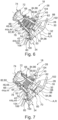
- Figure 6 shows the pedal assembly 18 in the unactuated state
- Figure 7 shows the pedal assembly 18 in the fully actuated state.
- the actuation rod 66 performs a purely translatory movement along the rod axis R and along the channel axis A when being operated.
- the portions of the actuation rod 66 being arranged inside the channel 44 guide this movement together with the channel 44.
- a relative position of the actuation rod 66 with respect to the guide part 40 is detected using the sensor assembly 94.
- the predetermined breaking zone 60 breaks such that the actuation rod 66 can travel even further into the guide piece 40 than in the fully actuated position.
- an excessive force is to be understood as a force having a substantially higher magnitude than a force being applied to the actuation rod 66 during normal operation.
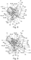
- Figures 9 to 11 show a second example of the pedal assembly 18.
- the pedal assembly comprises a retraction actuator 108 being coupled to the guide part 40.
- the retraction actuator 108 comprises an electric step motor 110 to which a transmission unit 112 is connected.
- the transmission unit 112 couples the electric step motor 110 to a pushrod 114.
- the pushrod 114 can be selectively moved out of the transmission unit 112 and can be selectively moved into the transmission unit 112.
- the second axial portion 78 is longer than in the first example.
- an actuation plate 116 is provided at the second end 70 of the actuation rod 66.
- the actuation plate 116 extends in a radial direction.
- a portion of the first axial section 76 and a portion of the second axial section 78 of the actuation rod 66 are arranged inside the channel 44.
- the second end 70 is arranged outside the channel 44.
- the actuation plate 116 and the pushrod 114 are arranged such that the pushrod 114 may push against the actuation plate 116 when being moved out of the transmission unit 112.
- the actuation rod 66 can be moved into a retracted position by operating the retraction actuator 108.
- the retraction actuator 108 is sufficiently powerful such that it can move the actuation rod against the biasing force of the biasing element 80.
- Moving the actuation rod 66 into the retracted position may be used in a situation in which the vehicle 10 is operated in a fully or partially autonomous driving mode in which an operation of the pedal assembly 18 by a foot of the driver is not necessary. Due to the fact that the actuation rod 66 is in the retracted position, more space for the driver's foot is available in the footwell area 24.
- the pedal assembly 18 according to the second example can be operated as has been explained in connection with the first example.
- the fully actuated position of the actuation rod 66 corresponds to the retracted position of the actuation rod 66.
- the predetermined breaking zone 60 may break if the vehicle is involved in the crash and an excessively high force is applied to the thrust piece and/or actuation rod 66. In such a case, the predetermined breaking zone 60 allows the actuation rod to travel even further into the guide piece 40 than in the fully actuated position.
- this functionality of the predetermined breaking zone 60 is available independent from the fact whether the pedal assembly 18, more precisely the actuation rod 66, is in a retracted position or not.
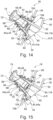
- Figures 12 to 14 show a third example of the pedal assembly 18.
- the sensor assembly 94 comprises a force sensor 118.
- the force sensor 118 is shaped as a cylindrical disc and is supported on the same side of the support element 52 as the biasing element 80. More precisely, the force sensor 118 is located between the biasing element 80 and the support element 52.
- the biasing element 80 which again is a wound coil spring 82, is shorter in an axial direction.
- the actuation rod 66 is shorter in the third example.
- the actuation rod neither extends through the wound coil spring 82 nor through the opening 54 of the support element 52. Rather, the second end 70 of the actuation rod 66 axially contacts the wound coil spring 82.
- the wound coil spring 82 is arranged between the second end 70 of the actuation rod 66 and the force sensor 118.
- the actuation rod 66 may be considered to comprise one axial section only between its first axial end 68 and its second axial end 70.
- the actuation rod 66 does not comprise am abutment element 88 in the third example.
- the force sensor 118 will output a detection result from which an magnitude of the force by which the pedal assembly 18 is actuated, i.e. a force that is applied to the pushing surface 74 can be read. This detection result can be fed into the control unit 20 such that the brake actuator 16 can be operated accordingly.
- the predetermined breaking zone 60 allows the actuation rod 66 to travel further into the guide part 40 than in the fully actuated position.
- a maximum travel path of the actuation rod 66 extending between the un-actuated position and the fully actuated position is shorter than in the first and the second example and even though no retraction actuator is represented in Figures 12 to 14 , it is of course possible to modify the third example such that also in this context, a retraction actuator 108 may be provided and the actuation rod 66 may be selectively moved into a retracted position.
- Figures 15 and 16 show a fourth example of the pedal assembly 18.
- the pedal assembly 18 according to the fourth example is a variation of the pedal assembly 18 according to the third example which has been explained in connection with Figures 12 to 14 .
- the biasing element 80 has been eliminated.
- the actuation rod 66 does not change its position when being operated. This means that the position of the actuation rod 66 is the same whether the actuation rod 66 is unactuated or fully actuated. Thus, Figure 15 may be considered to represent both the fully actuated position and the un-actuated position of the actuation rod 66.
- the pedal assembly 18 according to the fourth example is able to detect a force that is applied to the pushing surface 74 and is able to provide a corresponding detection result to the control unit 20 as has been explained in connection with the third example. In order to perform this functionality, a movement of the actuation rod 66 is not necessary.
- the predetermined breaking zone 60 allows the actuation rod 66 to travel further into the guide part 40 in a crash situation.
- the guide part 40, the mounting bracket 28, the actuation rod 66 and the sensor assembly 94 are provided as a pre-mounted subassembly.
- the biasing element 80 also forms part of the pre-mounted subassembly.
- the retraction actuator 108 also forms part of the pre-mounted subassembly.
- the pre-mounted subassembly is mounted on the structural part of the vehicle 10 by putting bolts 38 through the openings 36 of the mounting bracket 28.
- the sealing means 64 can be pulled over the guide part 40 and abutted against the connection collar 62.
- the carpet 26 is arranged in the footwell area 24 and placed over the pedal assembly 18 such that the guide part 40 extends through an opening in the carpet 26 and the rim of this opening contacts the attachment collar 106 of the sealing means 64.
- the carpet 26 and the attachment collar 106 of the sealing means 64 are attached to the connection collar 62 of the guide part 40 using bolts 104.
- the heads of these bolts 104 press the carpet 26 and the attachment collar 106 of the sealing means 64 against the connection collar 62.
- thrust piece 72 is connected to the first end 68 of the connection rod 66.
- the thrust piece 72 is clicked on the first end 68 of the connection rod 66.
Landscapes
- Engineering & Computer Science (AREA)
- Transportation (AREA)
- Mechanical Engineering (AREA)
- Physics & Mathematics (AREA)
- General Physics & Mathematics (AREA)
- Automation & Control Theory (AREA)
- Mechanical Control Devices (AREA)
- Braking Elements And Transmission Devices (AREA)
Abstract
The disclosure relates to a pedal assembly (18) for a vehicle. The pedal assembly (18) comprises a mounting bracket (28) having a mounting interface (30) for mechanically attaching the pedal assembly (18) to a structural part of the vehicle. Moreover, the pedal assembly (18) comprises a guide part (40) being fixedly connected to the mounting bracket (28) and comprising a channel (44) extending linearly along a channel axis (A). The pedal assembly (18) also comprises an actuation rod (66) extending along a rod axis (R) and having a first end (68) comprising or being coupled to a pushing surface (74). At least a portion of the actuation rod (66) is located inside the channel (44). The rod axis (R) and the channel axis (A) are parallel and the pushing surface (74) is configured to be contacted by a human foot for operating the pedal assembly (18). Furthermore, the pedal assembly (18) comprises a sensor assembly (94) being configured to detect an actuation of the actuation rod (66) along the rod axis (R). Additionally, a drive-by-wire system for a vehicle comprising such a pedal assembly (18) and a vehicle are described.
Description
- The present disclosure relates to a pedal assembly for a vehicle.
- The present disclosure also is directed to a drive-by-wire system for a vehicle.
- Moreover, the present disclosure relates to a vehicle comprising such a pedal assembly and/or such a drive-by-wire system.
- In a vehicle being driven by a human driver, a pedal assembly is one of the standard means being used by the human driver for operating the vehicle. The pedal assembly is for example a brake pedal assembly. The human driver can operate the vehicle's brakes by manipulating the brake pedal assembly. Alternatively, the pedal assembly may be an accelerator pedal assembly. The human driver can adjust an acceleration of the vehicle by manipulating the accelerator pedal assembly. The pedal assembly can also be a drive pedal assembly. A drive pedal assembly may be operated in order to adjust an acceleration of the vehicle. In this respect, the drive pedal assembly offers the same functionality as an accelerator pedal assembly. However, using a drive pedal assembly, the vehicle may also be decelerated. Thus, the drive pedal assembly additionally may offer a functionality which is otherwise provided by a brake pedal assembly.
- The pedal assembly may be mechanically coupled to the components of the vehicle being configured to provide the functionality being controlled by the operation of the pedal assembly. Thus, the pedal assembly may be mechanically connected to a brake system of the vehicle or to an engine of the vehicle.
- Alternatively, if the pedal assembly is used as a part of a drive-by-wire system, the pedal assembly and the components of the vehicle being configured to provide the functionality being controlled by the operation of the pedal assembly are only coupled by electric means, e.g. electric wires. In other words, in a drive-by-wire system, the pedal assembly is not mechanically coupled to the components of the vehicle being configured to provide the functionality being controlled by the operation of the pedal assembly.
- It is an objective of the present disclosure to improve known pedal assemblies. This is especially the case for pedal assemblies being used in drive-by-wire systems. The pedal assembly shall be structurally simple and compact.
- The problem is at least partially solved or alleviated by the subject matter of the independent claims of the present disclosure, wherein further examples are incorporated in the dependent claims.
- According to a first aspect, there is provided a pedal assembly for a vehicle. The pedal assembly comprises a mounting bracket having a mounting interface for mechanically attaching the pedal assembly to a structural part of the vehicle. Moreover, the pedal assembly comprises a guide part being fixedly connected to the mounting bracket and comprising a channel extending linearly along a channel axis. Additionally, the pedal assembly comprises an actuation rod extending along a rod axis and having a first end comprising or being coupled to a pushing surface. At least a portion of the actuation rod is located inside the channel. The rod axis and the channel axis are parallel and the pushing surface is configured to be contacted by a human foot for operating the pedal assembly. Furthermore, the pedal assembly comprises a sensor assembly being configured to detect an actuation of the actuation rod along the rod axis. Using the mounting bracket, the pedal assembly may be mechanically attached to the structural part of the vehicle in a simple and reliable manner. The mounting bracket may be configured to be mechanically attached to a floor component of the vehicle or a dashboard carrier component of the vehicle. The actuation rod having at least a portion thereof, e.g. its second end, located inside the linearly extending channel and the guide part are structurally simple. These parts offer a simple and compact actuation mechanism of the pedal assembly. In this context, the actuation rod and the guide part may be movable with respect to one another along the rod axis and the channel axis only. This means that the actuation rod may be moved along a linear trajectory when operating the pedal assembly. The channel and the guide part as a whole guide this movement. In an alternative, the actuation rod may be fixedly connected to the guide part such that a relative movement of the actuation rod with respect to the guide part is not possible. In both alternatives, the sensor assembly may detect an actuation of the actuation rod along the rod axis. This means that, using the sensor assembly, one may detect whether a user of the pedal assembly pushes the actuation rod via the pushing surface or not. At the same time a pushing intensity may be detected. The detection result of the sensor assembly may be used as a control input for a drive-by wire system. Moreover, in both alternatives, the pedal assembly is structurally simple. It comprises only comparatively few parts. Additionally, the pedal assembly is very compact.
- The basic idea underlying the present disclosure is to provide a pedal assembly, wherein the part of the pedal assembly that is actuated by a user of the pedal assembly, in the present disclosure the actuation rod, either perform a purely linear movement with respect to the part of the pedal assembly being fixedly arranged on the vehicle structure or no movement at all. In the present disclosure, the part being fixedly arranged on the vehicle structure is the guide part. Especially when considering known pedal assemblies comprising a plurality of levers being pivotably supported on one another or on a part being fixedly arranged on the vehicle structure, the pedal assembly according to the present disclosure is structurally simple and compact.
- In the present context, the channel is to be understood as an elongated volume having a length being at least three times the diameter. In an alternative, a length of the channel is at least five times the diameter. Such a channel can reliably guide the actuation rod when being actuated along the rod axis. In a case in which the actuation rod is not movable, the channel ensures that a reliable sensor signal is produced.
- It is understood that the pushing surface is the surface of the pedal assembly on which a user of the pedal assembly presses his or her foot in order to operate the pedal assembly. In a first alternative, the actuation rod comprises the pushing surface. This means that the actuation rod and the pushing surface are formed integrally. In this context, the actuation rod may comprise a plate-shaped portion at its first end. The pushing surface may be an end face of the plate-shaped portion. Alternatively, the pushing surface may simply be an end face of the actuation rod's first end. In a further alternative, the actuation rod is coupled to the pushing surface. This means that the pushing surface is provided on a part being separate from the actuation rod. Such a part may be called a thrust piece. This part is connected to the first end of the actuation rod. The part may be plate-shaped. The part may be connected to the first end of the actuation rod by any suitable means. In an example, the part is connected to the first end of the actuation rod via a clip. In another example, the part is glued or screwed to the first end of the actuation rod.
- It is noted that the mounting bracket and the guide part may be provided as parts being separate from one another which are connected by an appropriate means when forming the pedal assembly. The mounting bracket and the guide part may for example be connected by one or more welding seams, by one or more screws or by one or more clips. Alternatively, the mounting bracket and the guide part may be formed as a single integral part. This means that the mounting bracket is formed as one portion of this single integral part and the guide part is formed as another portion of the same single integral part.
- In an example, the pedal assembly is a brake pedal assembly. Thus, the detection result of the sensor assembly may be used as a control input for a brake system of the vehicle. As has been mentioned before, such a pedal assembly is structurally simple and very compact.
- In an example, the guide part comprises a support element. The support element is arranged in the channel. The actuation rod is axially supported on the support element. It is noted that the support element may be arranged at an end of the channel or at an intermediate position, i.e. between the ends of the channel. The support of the actuation rod on the support element may be direct, i.e. the actuation rod may directly contact the support element, or indirect, i.e. the actuation rod is supported on the support element via one or more intermediate parts. Providing such a support element is a simple and reliable way to support the actuation rod.
- The support element is for example disc-shaped. Such a support element is compact.
- In an example, the support element comprises an opening and the actuation rod extends through the opening. The portion of the actuation rod extending through the opening may have a reduced diameter with respect to the remaining portions of the actuation rod. This configuration allows the sensor assembly to be located on an opposite side of the support element as the pushing surface. This has the effect that the sensor element is located in a protected region of the pedal assembly. Thereby, the sensor assembly may be operated in a precise and reliable manner.
- Furthermore, in a configuration in which the actuation rod extends through the opening, an abutment surface defining an extreme position of the actuation rod may be provided on both sides of the support element. In other words, both sides of the support element may be used to limit a range of motion of the actuation rod along the rod axis.
- In an example, the support element comprises at least one predetermined breaking zone. In this context, a predetermined breaking zone is defined as a zone of the support element offering a predetermined mechanical resistance or mechanical stability being lower than the mechanical resistance or mechanical stability of the adjacent parts. This has the effect that in a situation in which a very high force is applied on the actuation rod, the predetermined breaking zone will be mechanically deformed or mechanically broken whereas the remaining parts of the pedal assembly remain mechanically intact. This is helpful in a situation in which the vehicle comprising the pedal assembly is involved in an accident or a crash. Due to the high forces to which the pedal assembly and especially the actuation rod may be subject in such a situation, the predetermined breaking zone will be mechanically deformed or mechanically broken such that a range of movement of the actuation rod is increased. Consequently, in such a situation, more room may be offered for the feet of the user of the pedal assembly. This increases crash safety for the user.
- In an example, the predetermined breaking zone comprises a plurality of slots. This means that the predetermined breaking zone is mechanically weakened by the plurality of slots. Using such slots, a mechanical resistance or mechanical stability may be adjusted in a precise and simple manner. Beyond that, a support element comprising a plurality of slots may be manufactured in the simple and cost-efficient manner.
- In an example, the pedal assembly further comprises a biasing element biasing the actuation rod into an unactuated position. This has two effects. A first effect relates to the fact that, due to the biasing element, the actuation rod always assumes the unactuated position, if no operational force acts thereon. Thus, the actuation rod always assumes a defined position such that the pedal assembly may be operated in a reliable manner. The second effect relates to the fact that the biasing element may provide a counterforce when being compressed during operation of the pedal assembly. This counterforce helps the user of the pedal assembly to precisely operate the pedal assembly.
- In an example, the biasing element comprises a spring element. The spring element may comprise a wound coil spring and/or an elastomeric spring element.
- In an example, the biasing element is supported on the support element. Thus, the biasing element is mechanically arranged between the actuation rod and the support element. In this context, the rod may be supported on the support element via the biasing element. This is a structurally simple and reliable configuration.
- In an example, the actuation rod comprises an abutment element being configured to abut against the guide part in an unactuated position of the actuation rod. In this context, the abutment element of the actuation rod may abut against the support element of the guide part. Consequently, the actuation rod may assume a well-defined position when being unactuated.
- In an example, the sensor assembly comprises a travel sensor being configured to detect a displacement of the actuation rod. Additionally or alternatively, the sensor assembly comprises a force sensor being configured to detect a force being applied to the actuation rod. Both the travel sensor and the force sensor allow to reliably detect an actuation of the pedal assembly, more precisely the actuation rod. Thus a system which is operated using the pedal assembly may be controlled in a precise manner. It is noted that the use of a travel sensor implies that the actuation rod moves relative to the guide part when being actuated. This is in contrast to the use of a force sensor which may be used in combination with a configuration in which the actuation rod may move relative to the guide part and also in combination with a configuration in which the actuation rod is not movable with respect to the guide part.
- In an example, the pedal assembly further comprises a sealing means being connected to the actuation rod and the guide part or the mounting bracket such that a contact region between the actuation rod and the guide part is protected against environmental influences. The sealing means may be effective in two directions. This means that influences resulting from a passenger compartment of the vehicle are not affecting the contact region between the actuation rod and the guide part. This especially applies to dirt and humidity which may be present in the passenger compartment. At the same time, the sealing means has the effect that influences from the interior of the pedal assembly and/or parts to which it is connected cannot reach the passenger compartment. This especially relates to dirt and lubrication means.
- In an example, the sealing means is sleeve-shaped and extends around a circumference of the actuation rod and the guide part. Consequently, the sealing means protects the contact region between the actuation rod and the gate part from all sides. In other words, the sealing effect is highly reliable.
- In this context, the sleeve-shaped sealing means may be a sealing bellow. Thus, the reliability of the sealing effect is not affected by a relative movement between the actuation rod and the guide part.
- In an example, the pedal assembly further comprises a retraction actuator being coupled to the guide part or the mounting bracket and being configured to selectively move the actuation rod towards an interior of the channel. The retraction actuator may be configured to move the actuation rod from an unactuated position into a retracted position wherein in the retracted position a manipulation of the actuation rod by a user's foot may not be possible anymore. The retraction actuator is very useful if the pedal assembly is used in a vehicle being able to drive in a fully or partially autonomous mode, wherein in the fully or partially autonomous drive mode a use of the pedal assembly is not required. If, in such a situation, the actuation rod is moved further into the channel, the pushing surface is moved away from a user's foot. This means that more space is provided for the user's foot in case the pedal assembly is not needed. Altogether, user comfort is enhanced.
- According to a second aspect, there is provided a drive-by-wire system for a vehicle comprising a pedal assembly according to the present disclosure. In a case in which the pedal assembly is a brake pedal assembly, the drive-by-wire system is a brake-by-wire system. Due to the fact that the pedal assembly is structurally simple and compact, also the drive-by-wire system is structurally simple and compact. Beyond that, all the effects and advantages that have been mentioned in connection with the pedal assembly according to the present disclosure also apply to the drive-by-wire system according to the present disclosure and vice versa.
- According to a third aspect, there is provided a vehicle comprising a drive by-wire system according to the present disclosure and/or a pedal assembly according to the present disclosure. The fact that the pedal assembly and/or the drive-by-wire system is structurally simple, also applies to the vehicle as such. Moreover, due to the fact that the pedal assembly and/or the drive-by-wire system is compact, the pedal assembly and/or the drive-by-wire system requires comparatively little space in the vehicle. This characteristic may be used to design the vehicle in a compact manner. Additionally or alternatively, this allows the vehicle to be designed in a manner that offers a comparatively large space to its users. Beyond that, all the effects and advantages that have been mentioned in connection with the pedal assembly and/or the drive-by-wire system also apply to the vehicle and vice versa.
- These and other aspects of the present disclosure will become apparent from and elucidated with reference to the examples described hereinafter.
- Examples of the disclosure will be described in the following with reference to the following drawings.
- Figure 1
- shows a vehicle according to the present disclosure comprising a drive-by-wire system according to the present disclosure and a pedal assembly according to the present disclosure,
- Figure 2
- shows a portion of a footwell area of the vehicle of
Figure 1 in a more detailed view, - Figure 3
- shows the portion of the footwell area of
Figure 2 , wherein a carpet is not shown, - Figure 4
- shows the pedal assembly of
Figures 1 to 3 in a more detailed, separate view, - Figure 5
- shows the pedal assembly of
Figure 4 along a viewing direction V inFigure 4 , - Figure 6
- shows the pedal assembly of
Figures 1 to 5 in a sectional view, wherein the pedal assembly is in an unactuated state, - Figure 7
- shows the pedal assembly of
Figure 6 in a fully actuated state, - Figure 8
- shows the pedal assembly of
Figures 6 and 7 in a crash state, - Figure 9
- shows another example of the pedal assembly in a sectional view, wherein the pedal assembly is in an unactuated state,
- Figure 10
- shows the pedal assembly of
Figure 9 , wherein the pedal assembly is in a retracted state, - Figure 11
- shows the pedal assembly of
Figure 9 and10 in a crash state, - Figure 12
- shows a further example of the pedal assembly in a sectional view, wherein the pedal assembly is in an unactuated state,
- Figure 13
- shows the pedal assembly of
Figure 9 , wherein the pedal assembly is in a fully actuated state, - Figure 14
- shows the pedal assembly of
Figure 12 and 13 in a crash state, - Figure 15
- shows a further example of the pedal assembly in a sectional view, and
- Figure 16
- shows the pedal assembly of
Figure 15 in a crash state. - The Figures are merely schematic representations and serve only to illustrate examples of the disclosure. Identical or equivalent elements are in principle provided with the same reference signs.
-
Figure 1 shows avehicle 10. - In the present example, the
vehicle 10 is a battery electric vehicle. - The vehicle comprises a drive-by-wire system 12 which in the present example is a brake-by-wire system 14.
- The brake-by-wire system 14 comprises a
brake actuator 16 for each of the vehicle's wheels, apedal assembly 18 and acontrol unit 20. - In the present example, the
pedal assembly 18 may be called a brake pedal assembly. - The
pedal assembly 18 is communicatively connected to thecontrol unit 20. Also thebrake actuators 16 are communicatively connected to thecontrol unit 20. In both cases, the communicative connection is realized by electric wires. - Consequently, using the
control unit 20, thebrake actuators 16 can be operated as a function of a position of thepedal assembly 18. - It is noted that in the present example, the
vehicle 10 additionally comprises a so-calledelectric accelerator pedal 22. However, in the following, the explanation will focus on thepedal assembly 18, i.e. the brake pedal assembly. -
Figures 2 and 3 show afootwell area 24 of thevehicle 10 comprising thepedal assembly 18 and theelectric accelerator pedal 22 in more detail. - In
Figure 2 , a portion of thepedal assembly 18 and a portion of theelectric accelerator pedal 22 is covered by acarpet 26 covering a floor area of thefootwell area 24. - In
Figure 3 , thecarpet 26 is not represented in order to better illustrate thepedal assembly 18 and theelectric accelerator pedal 22. - A first example of the
pedal assembly 18 will be explained with reference toFigures 4 to 8 . - The
pedal assembly 18 comprises a mountingbracket 28 having a mountinginterface 30 for mechanically attaching thepedal assembly 18 to a structural part of thevehicle 10. - In the present example, the structural part of the
vehicle 10 is a dashboard carrier. - Moreover, in the present example, the mounting
bracket 28 comprises acentral carrier portion 32 and a total of threeleg portions 34. - The mounting
bracket 28 is made of a flat material, wherein the threeleg portions 34 are bent with respect to thecentral carrier portion 32 such that the ends of the threeleg portions 34 are offset with respect to thecentral carrier portion 32. - Each of the three
leg portions 34 comprises anopening 36 such that the mountingbracket 28 can be connected to the structural part of thevehicle 10 usingbolts 38 extending through the openings 36 (see especiallyFigure 3 ). - Altogether, the mounting
bracket 28 has a triangular shape wherein each of the threeleg portions 34 is arranged in a corner of the triangular shape. - The
pedal assembly 18 also comprises aguide part 40 which in the present example is formed integrally with the mountingbracket 28. This means that in the present example, the mountingbracket 28 and theguide part 40 are formed as portions of one single part. - Due to the integral configuration, the
guide part 40 is fixedly connected to the mountingbracket 28. - It is understood that it is also possible to fixedly connect the
guide part 40 to the mountingbracket 28 other than integrally forming those two parts. In a case in which the mountingbracket 28 and theguide part 40 are formed as separate parts, they can for example be fixedly connected by welding or gluing or screwing. - The
guide part 40 comprises amain body 42 which in the present example is shaped as a truncated cone. - The
main body 42 is hollow and comprises achannel 44 extending linearly along a channel axis A. The channel axis A substantially corresponds to a middle axis of the truncated cone. - The
channel 44 has afirst portion 44a with a cylindrical shape and asecond portion 44b being shaped as a truncated cone. - At a first axial end 46, the
channel 44 is open. This means that the first axial end 46 of thechannel 44 is formed as an opening 48 having essentially the same diameter and cross-section as thefirst portion 44a of thechannel 44. - At a second axial and 50 of the
channel 44, thechannel 44 is also open. - The
first portion 44a and thesecond portion 44b are separated by asupport element 52. Thus, thesupport element 52 limits thefirst portion 44a and thesecond portion 44b in a direction parallel to the channel axis A. - The
support element 52 is shaped as a ring disc. - Since such a ring disc has an
opening 54 at its center, it only limits thechannel portions - An outer perimeter of the ring disc-shaped
support element 52 is connected to a wall of thechannel 44. - In the present example, the
support element 52 forms an integral part of theguide part 40. This means that themain body 42 and thesupport element 52 are formed by a single part. - The
support element 52 further comprises a plurality ofslots 56 extending radially from theopening 54 towards a perimeter of thesupport element 52. - In the present example, the
slots 56 merge into theopening 54, but end before having reached the outer perimeter of thesupport element 52. - Moreover, the
slots 56 are evenly distributed over a circumference of thesupport element 52. Consequently, theslots 56 are arranged in a star shape. - Due to the fact that the
slots 56 merge into theopening 54,tongues 58 of a substantially triangular form are formed between neighboringslots 56. - The
tongues 58 and theslots 56 form apredetermined breaking zone 60. The use and purpose of this predetermined breakingzone 60 will be explained further below. - It is understood that due to the fact that the
slots 56 are provided in thesupport element 52, thesupport element 52 is mechanically weakened when being compared to asupport element 52 withoutslots 56. - The
guide part 40 additionally comprises aconnection collar 62 at its outer circumference. - The
connection collar 62 is ring-shaped. It is used to attach thecarpet 26 and a sealing means 64 to theguide part 40 as will be explained further below. - Also the
connection collar 62 is integrally formed with themain body 42 in the present example. - The
connection collar 62 is offset from the mountingbracket 28 along the middle axis of themain body 42. - Moreover, the
connection collar 62 is arranged at an angle with respect to the mountingbracket 28. This means that theconnection collar 62 and the mountingbracket 28 are non-parallel. - In the present example, the
connection collar 62 and the mountingbracket 28 enclose an angle of approximately 30° (see especiallyFigure 6 ). - Additionally, the
pedal assembly 18 comprises anactuation rod 66. - The
actuation rod 66 is an elongated part which extends along a rod axis R. - In a situation in which the
actuation rod 66 is mounted within thepedal assembly 18, the rod axis R extends in parallel to the channel axis A. More precisely, the channel axis A and the rod axis R coincide. - In the present example, the
actuation rod 66 comprises a plurality of cylindrical sections wherein each of the cylindrical sections has a substantially circular cross-section. - The
actuation rod 66 has afirst end 68 which is an axial end and asecond end 70 which also is an axial end. Thesecond end 70 and thefirst end 68 are arranged on opposite sides of theactuation rod 66. - A
thrust piece 72 comprising a pushingsurface 74 being configured to be contacted by a human foot for operating thepedal assembly 18 is coupled to thefirst end 68 of theactuation rod 66. - This means that the pushing
surface 74 is coupled to thefirst end 68 of theactuation rod 66. - Adjacent to the
first end 68, theactuation rod 66 comprises a firstaxial section 76 of a first diameter meter. - In between an end of the first
axial section 76 being opposed to thefirst end 68 of theactuation rod 66 and thesecond end 70, theactuation rod 66 comprises a secondaxial section 78 of a second diameter. The second diameter is smaller than the first diameter. - The
second end 70, the secondaxial section 78 and a portion of the firstaxial section 76 are arranged inside thechannel 44. - The
actuation rod 66 is supported on thesupport element 52 via a biasing element 80 which in the present example is a wound coil spring 82. More generally speaking, theactuation rod 66 is axially supported on thesupport element 52 in an indirect manner. - The biasing element 80 biases the
actuation rod 66 towards its unactuated position as shown inFigure 6 and as will be explained further below. - In other words, the biasing element 80 or wound coil spring 82 is interposed between the
support element 52 and the firstaxial section 76 of theactuation rod 66. In this context, the biasing element 80 or wound coil spring 82 abuts against thesupport element 52 and the firstaxial section 76 in an axial direction. - Additionally, a dampening means 84 is interposed between the wound coil spring 82 and the
support element 52. - In the present example, the dampening means 84 is a ring-shaped rubber disc 86.
- The dampening means 84 is configured to dampen an abutment of the first
axial section 76 or the wound coil spring 82 on thesupport element 52. - The second
axial section 78 of theactuation rod 66 extends through theopening 54 of thesupports element 52. - At an axial position being arranged on an opposite side of the
support element 52 with respect to the biasing element 80, theactuation rod 66 comprises anabutment element 88. - The abutment element is a ring-shaped disc which extends around a circumference of the second
axial section 78 of theactuation rod 66. - The
abutment element 88 is configured to abut against theguide part 40, more precisely against thesupport element 52, in an unactuated position of the actuation rod 66 (cf.Figure 6 ). - In order to dampen such an abutment, another dampening means 90 is arranged on a surface of the
support element 52 facing theabutment element 88. - As before, the dampening means 90 is a ring-shaped rubber disc 92.
- Altogether, the
actuation rod 66 is movable relative to theguide part 40 between a fully actuated position (cf.Figure 7 ) and an unactuated position (cf.Figure 6 ). - In an unactuated position, the
abutment element 88 abuts against thesupport element 52 via rubber disc 92. In the fully actuated position, the firstaxial section 76 abuts against the support element via the wound coil spring 82 and the rubber disc 86. - The
actuation rod 66 is biased towards the unactuated position by the wound coil spring 82. - The
pedal assembly 18 further comprises a sensor assembly 94. - In the example of
Figures 4 to 8 , the sensor assembly 94 comprises a travel sensor 96. - The travel sensor 96 is configured to detect a displacement of the
actuation rod 66. - In the present example, the travel sensor 96 comprises a
detector coil 98 and a plurality ofmagnetic elements 100. - The
magnetic elements 100 are integrated into theactuation rod 66 or mounted thereon. Thedetector coil 98 is attached to theguide part 40. Consequently, using thedetector coil 98 and themagnetic elements 100, a position of theactuation rod 66 may be detected and a corresponding sensor signal may be provided to thecontrol unit 20 via anelectric communication interface 102. - More generally speaking, the sensor assembly 94 is configured to detect an actuation of the
actuation rod 66 along the rod axis R. - The
pedal assembly 18 further comprises the sealing means 64. - The sealing means 64 is configured to protect a contact region between the
actuation rod 66 and theguide part 40 against undesired environmental influences such as humidity. - In the present example, the sealing means 64 is sleeve-shaped and extends around the circumference of the
actuation rod 66 and theguide part 40. - A first end of the sealing means 64 is attached to the
actuation rod 66 at a position adjacent to thefirst end 68 of theactuation rod 66. It is understood that the sealing means 64 is connected to theactuation rod 66 in a water-tight manner. - A second end of the sealing means 64 being arranged opposite the first end of the sealing means 64 is connected to the
guide part 40, more precisely to theconnection collar 62. - It is understood that also the connection between the sealing means 64 and the
guide part 40 is water-tight. - In the present example, the sealing means 64 is connected to the
connection collar 62 using twobolts 104. - Moreover, the
same bolts 104 are used for connecting thecarpet 26 to theguide part 40. - To this end, the second end of the sealing means 64 is formed as an
attachment collar 106 which is directly placed on theconnection collar 62. - The
carpet 26 is placed over theattachment collar 106. - Then, both the
carpet 26 and theattachment collar 106 are compressed against theconnection collar 62 using thebolts 104. - As has been mentioned before,
Figure 6 shows thepedal assembly 18 in the unactuated state, whereasFigure 7 shows thepedal assembly 18 in the fully actuated state. - When comparing these two states, it can be seen that the
actuation rod 66 performs a purely translatory movement along the rod axis R and along the channel axis A when being operated. The portions of theactuation rod 66 being arranged inside thechannel 44 guide this movement together with thechannel 44. A relative position of theactuation rod 66 with respect to theguide part 40 is detected using the sensor assembly 94. - If the
vehicle 10 is involved in a crash which leads to the fact that an excessive force is applied on theactuation rod 66, thepredetermined breaking zone 60 breaks such that theactuation rod 66 can travel even further into theguide piece 40 than in the fully actuated position. - Thereby, space in the
footwell area 24 is increased. - In the present context, an excessive force is to be understood as a force having a substantially higher magnitude than a force being applied to the
actuation rod 66 during normal operation. -
Figures 9 to 11 show a second example of thepedal assembly 18. - In the following, only the differences with respect to the
pedal assembly 18 of the first example will be explained. Beyond that, reference is made to the above explanations which apply mutatis mutandis to the second example. - In the second example, the pedal assembly comprises a
retraction actuator 108 being coupled to theguide part 40. - More precisely, the
retraction actuator 108 comprises anelectric step motor 110 to which atransmission unit 112 is connected. - The
transmission unit 112 couples theelectric step motor 110 to apushrod 114. - Thus, by operating the
electric step motor 110, thepushrod 114 can be selectively moved out of thetransmission unit 112 and can be selectively moved into thetransmission unit 112. - As far as the
actuation rod 66 is concerned, in the second example, the secondaxial portion 78 is longer than in the first example. Beyond that, anactuation plate 116 is provided at thesecond end 70 of theactuation rod 66. Theactuation plate 116 extends in a radial direction. - Thus, in the second example, a portion of the first
axial section 76 and a portion of the secondaxial section 78 of theactuation rod 66 are arranged inside thechannel 44. Thesecond end 70 is arranged outside thechannel 44. - The
actuation plate 116 and thepushrod 114 are arranged such that thepushrod 114 may push against theactuation plate 116 when being moved out of thetransmission unit 112. - Consequently, the
actuation rod 66 can be moved into a retracted position by operating theretraction actuator 108. - It is understood, that the
retraction actuator 108 is sufficiently powerful such that it can move the actuation rod against the biasing force of the biasing element 80. - Moving the
actuation rod 66 into the retracted position may be used in a situation in which thevehicle 10 is operated in a fully or partially autonomous driving mode in which an operation of thepedal assembly 18 by a foot of the driver is not necessary. Due to the fact that theactuation rod 66 is in the retracted position, more space for the driver's foot is available in thefootwell area 24. - If the
retraction actuator 108 is not used, i.e. if thepushrod 114 is located inside thetransmission unit 112, thepedal assembly 18 according to the second example can be operated as has been explained in connection with the first example. - As far as the position of the
actuation rod 66 is concerned, the fully actuated position of theactuation rod 66 corresponds to the retracted position of theactuation rod 66. - As before, the
predetermined breaking zone 60 may break if the vehicle is involved in the crash and an excessively high force is applied to the thrust piece and/oractuation rod 66. In such a case, thepredetermined breaking zone 60 allows the actuation rod to travel even further into theguide piece 40 than in the fully actuated position. - It is noted that this functionality of the
predetermined breaking zone 60 is available independent from the fact whether thepedal assembly 18, more precisely theactuation rod 66, is in a retracted position or not. -
Figures 12 to 14 show a third example of thepedal assembly 18. - In the following, only the differences with respect to the
pedal assembly 18 of the first example and the second example will be explained. Beyond that, reference is made to the above explanations which apply mutatis mutandis to the third example. - The first difference lies in the fact that instead of the travel sensor, the sensor assembly 94 comprises a force sensor 118.
- The force sensor 118 is shaped as a cylindrical disc and is supported on the same side of the
support element 52 as the biasing element 80. More precisely, the force sensor 118 is located between the biasing element 80 and thesupport element 52. - As compared to the previous examples, the biasing element 80, which again is a wound coil spring 82, is shorter in an axial direction.
- Also the
actuation rod 66 is shorter in the third example. Here, the actuation rod neither extends through the wound coil spring 82 nor through theopening 54 of thesupport element 52. Rather, thesecond end 70 of theactuation rod 66 axially contacts the wound coil spring 82. - Thus, the wound coil spring 82 is arranged between the
second end 70 of theactuation rod 66 and the force sensor 118. - Even though the actuation rod comprises a varying diameter along its axial extension, the
actuation rod 66 may be considered to comprise one axial section only between its firstaxial end 68 and its secondaxial end 70. - Moreover, the
actuation rod 66 does not compriseam abutment element 88 in the third example. - When operating the
pedal assembly 18, a user will push theactuation rod 66 towards thesupport element 52 thereby compressing the wound coil spring 82. - In this context, the force sensor 118 will output a detection result from which an magnitude of the force by which the
pedal assembly 18 is actuated, i.e. a force that is applied to the pushingsurface 74 can be read. This detection result can be fed into thecontrol unit 20 such that thebrake actuator 16 can be operated accordingly. - As in the previous examples, the
predetermined breaking zone 60 allows theactuation rod 66 to travel further into theguide part 40 than in the fully actuated position. - It is noted that even though in the third example, a maximum travel path of the
actuation rod 66 extending between the un-actuated position and the fully actuated position is shorter than in the first and the second example and even though no retraction actuator is represented inFigures 12 to 14 , it is of course possible to modify the third example such that also in this context, aretraction actuator 108 may be provided and theactuation rod 66 may be selectively moved into a retracted position. -
Figures 15 and16 show a fourth example of thepedal assembly 18. - In the following, only the differences with respect to the
pedal assembly 18 of the previous examples will be explained. Beyond that, reference is made to the above explanations which apply mutatis mutandis to the fourth example. - The
pedal assembly 18 according to the fourth example is a variation of thepedal assembly 18 according to the third example which has been explained in connection withFigures 12 to 14 . - In contrast to the third example, in the fourth example, the biasing element 80 has been eliminated.
- Consequently, the
second end 70 of theactuation rod 66 directly contacts the force sensor 118. - In the fourth example, the
actuation rod 66 does not change its position when being operated. This means that the position of theactuation rod 66 is the same whether theactuation rod 66 is unactuated or fully actuated. Thus,Figure 15 may be considered to represent both the fully actuated position and the un-actuated position of theactuation rod 66. - The
pedal assembly 18 according to the fourth example is able to detect a force that is applied to the pushingsurface 74 and is able to provide a corresponding detection result to thecontrol unit 20 as has been explained in connection with the third example. In order to perform this functionality, a movement of theactuation rod 66 is not necessary. - Also in the fourth example, the
predetermined breaking zone 60 allows theactuation rod 66 to travel further into theguide part 40 in a crash situation. - In the following, a method for mounting the
pedal assembly 18 to thevehicle 10 will be explained. These explanations applied to all of the examples of thepedal assembly 18. - When mounting the
pedal assembly 18 to thevehicle 10, theguide part 40, the mountingbracket 28, theactuation rod 66 and the sensor assembly 94 are provided as a pre-mounted subassembly. - In a case in which the
pedal assembly 18 comprises a biasing element 80, the biasing element 80 also forms part of the pre-mounted subassembly. - In a case in which the
pedal assembly 18 comprises aretraction actuator 108, theretraction actuator 108 also forms part of the pre-mounted subassembly. - Based thereon, in a first step, the pre-mounted subassembly is mounted on the structural part of the
vehicle 10 by puttingbolts 38 through theopenings 36 of the mountingbracket 28. - Then, the sealing means 64 can be pulled over the
guide part 40 and abutted against theconnection collar 62. - Subsequently, the
carpet 26 is arranged in thefootwell area 24 and placed over thepedal assembly 18 such that theguide part 40 extends through an opening in thecarpet 26 and the rim of this opening contacts theattachment collar 106 of the sealing means 64. - Thereafter, the
carpet 26 and theattachment collar 106 of the sealing means 64 are attached to theconnection collar 62 of theguide part 40 usingbolts 104. The heads of thesebolts 104 press thecarpet 26 and theattachment collar 106 of the sealing means 64 against theconnection collar 62. - In a next step, thrust
piece 72 is connected to thefirst end 68 of theconnection rod 66. In the present example, thethrust piece 72 is clicked on thefirst end 68 of theconnection rod 66. - Other variations to the disclosed examples can be understood and effected by those skilled in the art in practicing the claimed disclosure, from the study of the drawings, the disclosure, and the appended claims. In the claims the word "comprising" does not exclude other elements or steps and the indefinite article "a" or "an" does not exclude a plurality. The mere fact that certain measures are recited in mutually different dependent claims does not indicate that a combination of these measures cannot be used to advantage. Any reference signs in the claims should not be construed as limiting the scope of the claims.
-
- 10
- vehicle
- 12
- drive-by-wire system
- 14
- brake-by-wire system
- 16
- brake actuator
- 18
- pedal assembly
- 20
- control unit
- 22
- electric accelerator pedal
- 24
- footwell area
- 26
- carpet
- 28
- mounting bracket
- 30
- mounting interface
- 32
- central carrier portion
- 34
- leg portion
- 36
- opening of the mounting bracket
- 38
- bolt
- 40
- guide part
- 42
- main body
- 44
- channel
- 44a
- first portion of the channel
- 44b
- second portion of the channel
- 46
- first axial end of the channel
- 48
- opening
- 50
- second axial end of the channel
- 52
- support element
- 54
- opening of the support element
- 56
- slot
- 58
- tongue
- 60
- predetermined breaking zone
- 62
- connection collar
- 64
- sealing means
- 66
- actuation rod
- 68
- first end of the actuation rod
- 70
- second end of the actuation rod
- 72
- thrust piece
- 74
- pushing surface
- 76
- first axial section of the actuation rod
- 78
- second axial section of the actuation rod
- 80
- biasing element
- 82
- wound coil spring
- 84
- dampening means
- 86
- rubber disc
- 88
- abutment element
- 90
- dampening means
- 92
- rubber disc
- 94
- sensor assembly
- 96
- travel sensor
- 98
- detector coil
- 100
- magnetic element
- 102
- electric communication interface
- 104
- bolt
- 106
- attachment collar
- 108
- retraction actuator
- 110
- electric step motor
- 112
- transmission unit
- 114
- pushrod
- 116
- actuation plate
- 118
- force sensor
- A
- channel axis
- R
- rod axis
Claims (15)
- A pedal assembly (18) for a vehicle (10), comprisinga mounting bracket (28) having a mounting interface (30) for mechanically attaching the pedal assembly (18) to a structural part of the vehicle (10),a guide part (40) being fixedly connected to the mounting bracket (28) and comprising a channel (44) extending linearly along a channel axis (A),an actuation rod (66) extending along a rod axis (R) and having a first end (68) comprising or being coupled to a pushing surface (74), wherein at least a portion of the actuation rod (66) is located inside the channel (44), wherein the rod axis (R) and the channel axis (A) are parallel and wherein the pushing surface (74) is configured to be contacted by a human foot for operating the pedal assembly (18), anda sensor assembly (94) being configured to detect an actuation of the actuation rod (66) along the rod axis (R).
- The pedal assembly (18) of claim 1, wherein the pedal assembly (18) is a brake pedal assembly.
- The pedal assembly (18) of claim 1 or 2, wherein the guide part (40) comprises a support element (52) being arranged in the channel (44), wherein the actuation rod (66) is axially supported on the support element (52).
- The pedal assembly (18) of claim 3, wherein the support element (52) comprises an opening (54) and wherein the actuation rod (66) extends through the opening (54).
- The pedal assembly (18) of claim 3 or 4, wherein the support element (52) comprises at least one predetermined breaking zone (60).
- The pedal assembly (18) of claim 5, wherein the predetermined breaking zone (60) comprises a plurality of slots (56).
- The pedal assembly (18) of any one of the preceding claims, further comprising a biasing element (80) biasing the actuation rod (66) into an unactuated position.
- The pedal assembly (18) of claim 7 and any one of claims 3 to 6, wherein the biasing element (80) is supported on the support element (52).
- The pedal assembly (18) of any one of the preceding claims, wherein the actuation rod (66) comprises an abutment element (88) being configured to abut against the guide part (40) in an unactuated position of the actuation rod (66).
- The pedal assembly (18) of any one of the preceding claims,wherein the sensor assembly (94) comprises a travel sensor (96) being configured to detect a displacement of the actuation rod (66) and/orwherein the sensor assembly (94) comprises a force sensor (118) being configured to detect a force being applied to the actuation rod (66).
- The pedal assembly (18) of any one of the preceding claims, further comprising a sealing means (64) being connected to the actuation rod (66) and the guide part (40) or the mounting bracket (28) such that a contact region between the actuation rod (66) and the guide part (40) is protected against environmental influences.
- The pedal assembly (18) of claim 13, wherein the sealing means (64) is sleeve-shaped and extends around a circumference of the actuation rod (66) and the guide part (40).
- The pedal assembly (18) of any one of the preceding claims, further comprising a retraction actuator (108) being coupled to the guide part (40) or the mounting bracket (28) and being configured to selectively move the actuation rod (66) towards an interior of the channel (44).
- A drive-by-wire system (12) for a vehicle (10) comprising a pedal assembly (18) according to any one of the preceding claims.
- A vehicle (10) comprising a drive by-wire system (12) according to claim 14 and/or a pedal assembly (18) according to any one of claims 1 to 13.
Priority Applications (3)
| Application Number | Priority Date | Filing Date | Title |
|---|---|---|---|
| EP23153766.3A EP4407404A1 (en) | 2023-01-27 | 2023-01-27 | Pedal assembly for a vehicle, drive-by-wire system for a vehicle, and vehicle |
| US18/422,413 US12403871B2 (en) | 2023-01-27 | 2024-01-25 | Pedal assembly for a vehicle |
| CN202410115296.5A CN118405098A (en) | 2023-01-27 | 2024-01-26 | Pedal assembly for vehicle, drive-by-wire system for vehicle and vehicle |
Applications Claiming Priority (1)
| Application Number | Priority Date | Filing Date | Title |
|---|---|---|---|
| EP23153766.3A EP4407404A1 (en) | 2023-01-27 | 2023-01-27 | Pedal assembly for a vehicle, drive-by-wire system for a vehicle, and vehicle |
Publications (1)
| Publication Number | Publication Date |
|---|---|
| EP4407404A1 true EP4407404A1 (en) | 2024-07-31 |
Family
ID=85132965
Family Applications (1)
| Application Number | Title | Priority Date | Filing Date |
|---|---|---|---|
| EP23153766.3A Pending EP4407404A1 (en) | 2023-01-27 | 2023-01-27 | Pedal assembly for a vehicle, drive-by-wire system for a vehicle, and vehicle |
Country Status (3)
| Country | Link |
|---|---|
| US (1) | US12403871B2 (en) |
| EP (1) | EP4407404A1 (en) |
| CN (1) | CN118405098A (en) |
Cited By (1)
| Publication number | Priority date | Publication date | Assignee | Title |
|---|---|---|---|---|
| US20240308481A1 (en) * | 2023-03-14 | 2024-09-19 | Ford Global Technologies, Llc | Stowable vehicle pedal system and method |
Families Citing this family (3)
| Publication number | Priority date | Publication date | Assignee | Title |
|---|---|---|---|---|
| US12467808B2 (en) * | 2022-03-17 | 2025-11-11 | Sensata Technologies, Inc. | Brake pedal with force sensor and membranes |
| EP4385786A1 (en) * | 2022-12-16 | 2024-06-19 | Volvo Car Corporation | Accelerator pedal bracket assembly for a vehicle, accelerating pedal assembly for a vehicle, vehicle comprisng accelerating pedal assembly with accelerator pedal bracket assembly and method for protecting a driver with accelerato pedal bracket assembly |
| CN120288002A (en) * | 2025-05-19 | 2025-07-11 | 苏州坐标系智能科技有限公司 | An electrically adjustable wire-controlled pedal structure |
Citations (2)
| Publication number | Priority date | Publication date | Assignee | Title |
|---|---|---|---|---|
| EP0500888B1 (en) * | 1990-09-15 | 1996-01-24 | ITT Automotive Europe GmbH | Foot-pedal unit for motor vehicles |
| US20210004040A1 (en) * | 2019-07-01 | 2021-01-07 | Ford Global Technologies, Llc | Pedal unit for a motor vehicle |
Family Cites Families (5)
| Publication number | Priority date | Publication date | Assignee | Title |
|---|---|---|---|---|
| GB375591A (en) * | 1931-07-31 | 1932-06-30 | Allan Riley | Improvements relating to motor vehicle bodies |
| US4991457A (en) * | 1990-05-14 | 1991-02-12 | Chrysler Corporation | Shift boot support and bezel arrangement |
| DE102014103167A1 (en) * | 2014-03-10 | 2015-09-24 | Ab Elektronik Gmbh | pedal unit |
| KR102771521B1 (en) * | 2020-08-12 | 2025-02-21 | 현대자동차주식회사 | Foldable brake pedal apparatus for autonomous driving vehicle |
| KR20230096205A (en) * | 2021-12-22 | 2023-06-30 | 현대자동차주식회사 | Organ type electronic pedal apparatus |
-
2023
- 2023-01-27 EP EP23153766.3A patent/EP4407404A1/en active Pending
-
2024
- 2024-01-25 US US18/422,413 patent/US12403871B2/en active Active
- 2024-01-26 CN CN202410115296.5A patent/CN118405098A/en active Pending
Patent Citations (2)
| Publication number | Priority date | Publication date | Assignee | Title |
|---|---|---|---|---|
| EP0500888B1 (en) * | 1990-09-15 | 1996-01-24 | ITT Automotive Europe GmbH | Foot-pedal unit for motor vehicles |
| US20210004040A1 (en) * | 2019-07-01 | 2021-01-07 | Ford Global Technologies, Llc | Pedal unit for a motor vehicle |
Cited By (2)
| Publication number | Priority date | Publication date | Assignee | Title |
|---|---|---|---|---|
| US20240308481A1 (en) * | 2023-03-14 | 2024-09-19 | Ford Global Technologies, Llc | Stowable vehicle pedal system and method |
| US12337809B2 (en) * | 2023-03-14 | 2025-06-24 | Ford Global Technologies, Llc | Stowable vehicle pedal system and method |
Also Published As
| Publication number | Publication date |
|---|---|
| CN118405098A (en) | 2024-07-30 |
| US12403871B2 (en) | 2025-09-02 |
| US20240253601A1 (en) | 2024-08-01 |
Similar Documents
| Publication | Publication Date | Title |
|---|---|---|
| EP4407404A1 (en) | Pedal assembly for a vehicle, drive-by-wire system for a vehicle, and vehicle | |
| US10948941B2 (en) | Pedal unit for a motor vehicle | |
| US11072316B2 (en) | Braking device for a hydraulic motor vehicle braking system having a ball screw drive | |
| US11820350B2 (en) | Brake pedal module | |
| US20100242469A1 (en) | Brake actuating unit | |
| KR20100095575A (en) | Break system comprising a clutch shiftable by the break pedal for disengaging the drive device from the piston-cylinder unit | |
| KR20140030227A (en) | Pedal travel simulator, actuating unit for a hydraulic brake system and brake system | |
| JP7472850B2 (en) | Pedal device | |
| US12128866B2 (en) | Electrically activatable actuating unit for a motor vehicle brake system, brake booster having such an electrically activatable actuating unit and motor vehicle brake system having such a brake booster | |
| US20150184713A1 (en) | Actuator for a functional unit of a motor vehicle | |
| US12024143B2 (en) | Brake pedal module | |
| JP2012526013A (en) | Brake actuation unit for actuating an automobile brake system | |
| JP4612993B2 (en) | Master cylinder for an electrohydraulic braking system with improved pedal feel simulation means and electrohydraulic braking system with such a master cylinder | |
| US12583422B2 (en) | Brake pedal module | |
| EP3418142B1 (en) | Drum brake system | |
| EP3470279A1 (en) | Electric parking brake system | |
| US20030019696A1 (en) | Parking brake device including pivotable brake lever which extends through aperture of backing plate | |
| US20250033609A1 (en) | Brake pedal device | |
| CN120828780A (en) | Pedal unit for operating vehicle functions | |
| US11820349B2 (en) | Pneumatic brake pedal module | |
| US20230033814A1 (en) | Pneumatic brake pedal module | |
| US12420633B2 (en) | Pedal unit for a vehicle | |
| EP0768223B1 (en) | Brake cylinder means for a motor vehicle | |
| EP4159558B1 (en) | Foot brake device for vehicles | |
| CN121626059A (en) | Anti-lock braking system (ABS) electrical control device for motor vehicles |
Legal Events
| Date | Code | Title | Description |
|---|---|---|---|
| PUAI | Public reference made under article 153(3) epc to a published international application that has entered the european phase |
Free format text: ORIGINAL CODE: 0009012 |
|
| STAA | Information on the status of an ep patent application or granted ep patent |
Free format text: STATUS: REQUEST FOR EXAMINATION WAS MADE |
|
| 17P | Request for examination filed |
Effective date: 20231026 |
|
| AK | Designated contracting states |
Kind code of ref document: A1 Designated state(s): AL AT BE BG CH CY CZ DE DK EE ES FI FR GB GR HR HU IE IS IT LI LT LU LV MC ME MK MT NL NO PL PT RO RS SE SI SK SM TR |