EP4407376A1 - Image forming apparatus, method for processing information relating to recording medium, and program - Google Patents
Image forming apparatus, method for processing information relating to recording medium, and program Download PDFInfo
- Publication number
- EP4407376A1 EP4407376A1 EP24152360.4A EP24152360A EP4407376A1 EP 4407376 A1 EP4407376 A1 EP 4407376A1 EP 24152360 A EP24152360 A EP 24152360A EP 4407376 A1 EP4407376 A1 EP 4407376A1
- Authority
- EP
- European Patent Office
- Prior art keywords
- recording medium
- information relating
- sheet
- image forming
- forming apparatus
- Prior art date
- Legal status (The legal status is an assumption and is not a legal conclusion. Google has not performed a legal analysis and makes no representation as to the accuracy of the status listed.)
- Pending
Links
- 238000000034 method Methods 0.000 title claims description 27
- 238000012545 processing Methods 0.000 title claims description 14
- 238000001514 detection method Methods 0.000 claims description 125
- 238000010586 diagram Methods 0.000 description 16
- 230000003287 optical effect Effects 0.000 description 16
- 230000000704 physical effect Effects 0.000 description 16
- 230000006870 function Effects 0.000 description 12
- 239000000463 material Substances 0.000 description 12
- 238000012790 confirmation Methods 0.000 description 6
- 238000004891 communication Methods 0.000 description 4
- 238000012937 correction Methods 0.000 description 4
- 238000012546 transfer Methods 0.000 description 4
- 230000015572 biosynthetic process Effects 0.000 description 3
- 238000002834 transmittance Methods 0.000 description 3
- 238000011144 upstream manufacturing Methods 0.000 description 3
- 230000005540 biological transmission Effects 0.000 description 2
- 239000003795 chemical substances by application Substances 0.000 description 2
- 239000011248 coating agent Substances 0.000 description 2
- 238000006073 displacement reaction Methods 0.000 description 2
- 239000000945 filler Substances 0.000 description 2
- 239000011347 resin Substances 0.000 description 2
- 229920005989 resin Polymers 0.000 description 2
- 239000004753 textile Substances 0.000 description 2
- 230000004397 blinking Effects 0.000 description 1
- 239000003086 colorant Substances 0.000 description 1
- 230000001276 controlling effect Effects 0.000 description 1
- 230000000694 effects Effects 0.000 description 1
- 239000011521 glass Substances 0.000 description 1
- 238000010438 heat treatment Methods 0.000 description 1
- 239000004973 liquid crystal related substance Substances 0.000 description 1
- 230000002093 peripheral effect Effects 0.000 description 1
- 238000003825 pressing Methods 0.000 description 1
- 230000001105 regulatory effect Effects 0.000 description 1
- 230000002269 spontaneous effect Effects 0.000 description 1
- 230000003068 static effect Effects 0.000 description 1
- 239000013589 supplement Substances 0.000 description 1
Images



Classifications
-
- G—PHYSICS
- G03—PHOTOGRAPHY; CINEMATOGRAPHY; ANALOGOUS TECHNIQUES USING WAVES OTHER THAN OPTICAL WAVES; ELECTROGRAPHY; HOLOGRAPHY
- G03G—ELECTROGRAPHY; ELECTROPHOTOGRAPHY; MAGNETOGRAPHY
- G03G15/00—Apparatus for electrographic processes using a charge pattern
- G03G15/50—Machine control of apparatus for electrographic processes using a charge pattern, e.g. regulating differents parts of the machine, multimode copiers, microprocessor control
- G03G15/5029—Machine control of apparatus for electrographic processes using a charge pattern, e.g. regulating differents parts of the machine, multimode copiers, microprocessor control by measuring the copy material characteristics, e.g. weight, thickness
-
- G—PHYSICS
- G03—PHOTOGRAPHY; CINEMATOGRAPHY; ANALOGOUS TECHNIQUES USING WAVES OTHER THAN OPTICAL WAVES; ELECTROGRAPHY; HOLOGRAPHY
- G03G—ELECTROGRAPHY; ELECTROPHOTOGRAPHY; MAGNETOGRAPHY
- G03G15/00—Apparatus for electrographic processes using a charge pattern
- G03G15/50—Machine control of apparatus for electrographic processes using a charge pattern, e.g. regulating differents parts of the machine, multimode copiers, microprocessor control
- G03G15/5016—User-machine interface; Display panels; Control console
-
- G—PHYSICS
- G03—PHOTOGRAPHY; CINEMATOGRAPHY; ANALOGOUS TECHNIQUES USING WAVES OTHER THAN OPTICAL WAVES; ELECTROGRAPHY; HOLOGRAPHY
- G03G—ELECTROGRAPHY; ELECTROPHOTOGRAPHY; MAGNETOGRAPHY
- G03G15/00—Apparatus for electrographic processes using a charge pattern
- G03G15/50—Machine control of apparatus for electrographic processes using a charge pattern, e.g. regulating differents parts of the machine, multimode copiers, microprocessor control
- G03G15/5075—Remote control machines, e.g. by a host
-
- G—PHYSICS
- G03—PHOTOGRAPHY; CINEMATOGRAPHY; ANALOGOUS TECHNIQUES USING WAVES OTHER THAN OPTICAL WAVES; ELECTROGRAPHY; HOLOGRAPHY
- G03G—ELECTROGRAPHY; ELECTROPHOTOGRAPHY; MAGNETOGRAPHY
- G03G15/00—Apparatus for electrographic processes using a charge pattern
- G03G15/65—Apparatus which relate to the handling of copy material
- G03G15/6502—Supplying of sheet copy material; Cassettes therefor
-
- G—PHYSICS
- G03—PHOTOGRAPHY; CINEMATOGRAPHY; ANALOGOUS TECHNIQUES USING WAVES OTHER THAN OPTICAL WAVES; ELECTROGRAPHY; HOLOGRAPHY
- G03G—ELECTROGRAPHY; ELECTROPHOTOGRAPHY; MAGNETOGRAPHY
- G03G15/00—Apparatus for electrographic processes using a charge pattern
- G03G15/65—Apparatus which relate to the handling of copy material
- G03G15/6555—Handling of sheet copy material taking place in a specific part of the copy material feeding path
- G03G15/6558—Feeding path after the copy sheet preparation and up to the transfer point, e.g. registering; Deskewing; Correct timing of sheet feeding to the transfer point
-
- G—PHYSICS
- G03—PHOTOGRAPHY; CINEMATOGRAPHY; ANALOGOUS TECHNIQUES USING WAVES OTHER THAN OPTICAL WAVES; ELECTROGRAPHY; HOLOGRAPHY
- G03G—ELECTROGRAPHY; ELECTROPHOTOGRAPHY; MAGNETOGRAPHY
- G03G15/00—Apparatus for electrographic processes using a charge pattern
- G03G15/65—Apparatus which relate to the handling of copy material
- G03G15/6588—Apparatus which relate to the handling of copy material characterised by the copy material, e.g. postcards, large copies, multi-layered materials, coloured sheet material
-
- G—PHYSICS
- G03—PHOTOGRAPHY; CINEMATOGRAPHY; ANALOGOUS TECHNIQUES USING WAVES OTHER THAN OPTICAL WAVES; ELECTROGRAPHY; HOLOGRAPHY
- G03G—ELECTROGRAPHY; ELECTROPHOTOGRAPHY; MAGNETOGRAPHY
- G03G2215/00—Apparatus for electrophotographic processes
- G03G2215/00362—Apparatus for electrophotographic processes relating to the copy medium handling
- G03G2215/00443—Copy medium
- G03G2215/00514—Envelopes
-
- G—PHYSICS
- G03—PHOTOGRAPHY; CINEMATOGRAPHY; ANALOGOUS TECHNIQUES USING WAVES OTHER THAN OPTICAL WAVES; ELECTROGRAPHY; HOLOGRAPHY
- G03G—ELECTROGRAPHY; ELECTROPHOTOGRAPHY; MAGNETOGRAPHY
- G03G2215/00—Apparatus for electrophotographic processes
- G03G2215/00362—Apparatus for electrophotographic processes relating to the copy medium handling
- G03G2215/00535—Stable handling of copy medium
- G03G2215/00611—Detector details, e.g. optical detector
- G03G2215/00616—Optical detector
-
- G—PHYSICS
- G03—PHOTOGRAPHY; CINEMATOGRAPHY; ANALOGOUS TECHNIQUES USING WAVES OTHER THAN OPTICAL WAVES; ELECTROGRAPHY; HOLOGRAPHY
- G03G—ELECTROGRAPHY; ELECTROPHOTOGRAPHY; MAGNETOGRAPHY
- G03G2215/00—Apparatus for electrophotographic processes
- G03G2215/00362—Apparatus for electrophotographic processes relating to the copy medium handling
- G03G2215/00535—Stable handling of copy medium
- G03G2215/00611—Detector details, e.g. optical detector
- G03G2215/00637—Acoustic detector
-
- G—PHYSICS
- G03—PHOTOGRAPHY; CINEMATOGRAPHY; ANALOGOUS TECHNIQUES USING WAVES OTHER THAN OPTICAL WAVES; ELECTROGRAPHY; HOLOGRAPHY
- G03G—ELECTROGRAPHY; ELECTROPHOTOGRAPHY; MAGNETOGRAPHY
- G03G2215/00—Apparatus for electrophotographic processes
- G03G2215/00362—Apparatus for electrophotographic processes relating to the copy medium handling
- G03G2215/00535—Stable handling of copy medium
- G03G2215/00717—Detection of physical properties
- G03G2215/00751—Detection of physical properties of sheet type, e.g. OHP
Definitions
- the present invention relates to an image forming apparatus such as a copying machine, a printer, or a digital multifunction apparatus called a multifunction peripheral (MFP), a method for processing information relating to a recording medium, and a program.
- an image forming apparatus such as a copying machine, a printer, or a digital multifunction apparatus called a multifunction peripheral (MFP)
- MFP multifunction peripheral
- a user who uses an image forming apparatus wants to select an output sheet by checking what kind of sheet is contained in a sheet feed tray.
- by setting sheet information of a sheet in the sheet feed tray it is possible to check the sheet information without going to the apparatus.
- a user may randomly add different types of sheets to the sheet feed tray.
- the sheet information of the sheet feed tray is no longer up to date.
- the latest sheet information is not reported, the user cannot grasp the latest status.
- a sheet history of the sheet feed tray is unknown, it is difficult to determine whether the sheet feed tray is available.
- Patent Literature 1 Japanese Unexamined Patent Application Publication No. 2022-89505 discloses that a medium detection sensor mounted in an image forming apparatus identifies a physical property of a sheet and displays a type and a basis weight of the sheet.
- Patent Literature 2 Japanese Unexamined Patent Application Publication No. 2018-106112 discloses the following image forming apparatus.
- This image forming apparatus detects characteristics (medium characteristics) of a recording material conveyed to an image forming section.
- the image forming apparatus interrupts image forming processing when a detected first medium characteristic of a recording material being conveyed is different from a second medium characteristic of the recording material at the time of previous image formation stored in a RAM, and an image forming condition corresponding to the first medium characteristic is different from an image forming condition corresponding to the second medium characteristic.
- the image forming apparatus allows a user to input a medium characteristic by an input means after the interruption, and resumes the image forming operation under an image forming condition corresponding to the input medium characteristic.
- Patent Literatures 1 and 2 do not refer to notifying a user of the latest information relating to a sheet in a sheet feed tray. Therefore, in each of the image forming apparatuses described in Patent Literatures 1 and 2, a user cannot know the latest sheet information in a case where a sheet is added to a sheet feed tray. Patent Literatures 1 and 2 cannot provide a solution to the problem that it is difficult to determine whether the tray is available since the sheet history of the tray is unclear.
- An object of the present invention is to provide an image forming apparatus, a method for processing information relating to a recording medium, and a program capable of detecting and outputting the latest information relating to a sheet in a sheet feed tray.
- the image forming apparatus and the method for processing information relating to a recording medium information relating to a first recording medium conveyed first is detected, and information relating to a second recording medium conveyed after the first recording medium is detected. Then, since the detected information relating to the second recording medium after the first recording medium is output, a user can know the information relating to the second recording medium newer than the first recording medium conveyed first based on the output information. As a result, even when a recording medium different from the first recording medium is added to a sheet feed tray after the conveyance of the first recording medium, an opportunity to know information relating to recording media after the addition increases. Therefore, a user can grasp the latest sheet information relating to the sheet feed tray, and can easily determine whether the tray can be used.
- the program causes the computer of the image forming apparatus to execute conveying a first recording medium and a second recording medium and detecting information relating to the first recording medium and information relating to the second recording medium. Further, the program causes the computer to detect the information relating to the first recording medium conveyed first by the conveying and to detect the information relating to the second recording medium conveyed by the conveying after the first recording medium in the detecting. Then, the program causes the computer to execute outputting the detected information relating to the second recording medium after the first recording medium.
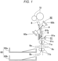
- Fig. 1 is a diagram schematically illustrating a part of a conveyance path for a recording medium (hereinafter, the recording medium is also referred to as a sheet or paper) on which an image is printed in an image forming apparatus 1 according to an embodiment of the present invention.
- the recording medium hereinafter, the recording medium is also referred to as a sheet or paper
- Examples of the image forming apparatus 1 include, but are not limited to, a copier, a printer, and an MFP which is a digital multifunction apparatus.
- a sheet feed section 60 is provided at a lower portion of the image forming apparatus 1.
- a first sheet feed tray 60a which is a first-stage sheet feed cassette in an upper stage
- a second sheet feed tray 60b which is a second-stage sheet feed cassette in a lower stage are arranged.
- a sheet conveyance path 8 is formed in a vertical direction so as to communicate with a sheet feed port 8a of the first sheet feed tray 60a and a sheet feed port 8b of the second sheet feed tray 60b.
- a sheet fed from the sheet feed port 8a of the first sheet feed tray 60a or the sheet feed port 8b of the second sheet feed tray 60b to the sheet conveyance path 8 is conveyed upward in the sheet conveyance path 8 as indicated by an arrow A.
- the sheet is conveyed to a pair of skew correction rollers 72 installed at the position of an upper portion of the sheet conveyance path 8 by conveyance rollers (corresponding to a sheet conveyance section) 71a and 71b, and the like.
- a manual sheet feed tray (not illustrated) is provided on the opposite side of the first sheet feed tray 60a with the sheet conveyance path 8 interposed therebetween.
- a sheet set on the manual sheet feed tray is supplied to the sheet conveyance path 8 via a manual sheet feed port 8c.
- Each of the first sheet feed tray 60a, the second sheet feed tray 60b, and the manual sheet feed tray corresponds to a holder that holds a sheet.
- a user can open and close the first sheet feed tray 60a, the second sheet feed tray 60b, and the manual sheet feed tray with respect to the image forming apparatus 1.
- Opening the first sheet feed tray 60a and the second sheet feed tray 60b means removing the first sheet feed tray (sheet feed cassette) 60a and the second sheet feed tray (sheet feed cassette) 60b from a main body of the apparatus for the purpose of replacement of a sheet, addition of a sheet, or the like.
- Opening the manual sheet feed tray means that a sheet is removed from the manual sheet feed tray to bring the manual sheet feed tray into a non-use state.
- closing the first sheet feed tray 60a and the second sheet feed tray 60b means attaching the first sheet feed tray 60a and the second sheet feed tray 60b to the main body of the apparatus.
- Closing the manual sheet feed tray means setting a sheet on the manual sheet feed tray and bringing the manual sheet feed tray into a use state.
- opening the first sheet feed tray 60a, the second sheet feed tray 60b, and the manual sheet feed tray is also referred to as opening the sheet feed ports 8a, 8b, and 8c.
- Closing the first sheet feed tray 60a, the second sheet feed tray 60b, and the manual sheet feed tray is also referred to as closing the sheet feed ports 8a, 8b, and 8c.
- the opening and closing of the first sheet feed tray 60a and the second sheet feed tray 60b can be detected by a sensor (not illustrated).
- the opening and closing of the manual sheet feed tray can be detected based on whether a sheet is present on the manual sheet feed tray.
- the skew correction rollers 72 are rollers for correcting skew (inclination) of a sheet conveyed in the sheet conveyance path 8.
- the medium detection sensors 91 and 92 detect a physical property value of a sheet that is an example of information relating to the sheet.
- the medium detection sensor 91 on the upstream side is an optical sensor that detects light emitted to the sheet.
- the medium detection sensor 92 on the downstream side is an ultrasonic sensor that detects an ultrasonic wave output toward the sheet.
- the optical sensor 91 may be disposed on the upstream side, and the ultrasonic sensor 92 may be disposed on the downstream side.
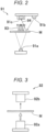
- Fig. 2 is an explanatory diagram illustrating the optical sensor 91.
- the optical sensor 91 includes a transmission light source 91a such as an LED, a reflection light source 91b such as an LED, and a light receiving element 91c such as a photodiode.
- the amount of transmitted light 93, which is light emitted from the transmission light source 91a and transmitted through a sheet M conveyed in the sheet conveyance path 8, and the amount of reflected light 94, which is light emitted from the reflection light source 91b and reflected by the sheet M, are detected as physical property values by the light receiving element 91c.
- a controller 100 described later determines the type of the sheet M (a basis weight, an OHP sheet, a recycled sheet, a coated sheet, or the like). Based on this determination, the controller 100 detects the type of sheet (sheet type) that is another example of the information relating to the sheet.
- the optical sensor 91 may include a plurality of sensor groups corresponding to red, green, and blue colors, for example.
- Fig. 3 is an explanatory diagram illustrating the ultrasonic sensor 92.
- the ultrasonic sensor 92 includes a pair of an ultrasonic transmitter 92a and an ultrasonic receiver 92b which are obliquely opposed to each other with the sheet conveyance path 8 interposed therebetween with respect to a direction in which the sheet M passes (see Fig. 1 ).
- the ultrasonic sensor 92 transmits an ultrasonic wave from the ultrasonic transmitter 92a to the passing sheet M, and receives the ultrasonic wave transmitted through the sheet M by the ultrasonic receiver 92b.
- the controller 100 detects the type of the sheet M as information relating to the sheet by determining whether the sheet M is a single sheet or a two-ply sheet (envelope) based on the amount of attenuation of the ultrasonic wave by the sheet M.
- the image forming apparatus 1 has a user designation mode and an automatic detection mode, and a user can select one of the modes.
- the user designation mode is a mode in which the user designates a sheet type.
- the detection of a physical property value of a sheet and the determination of the sheet type by the medium detection sensors 91 and 92 are not performed.
- the automatic detection mode is selected, the detection and the determination of the sheet type by the medium detection sensors 91 and 92 are performed.
- Fig. 4 is a block diagram illustrating an electrical configuration of the image forming apparatus 1.
- the image forming apparatus 1 includes the controller 100, a storage device 110, an image reading device 120, an operation panel section 50, an image forming section 10, the sheet feed section 60, the optical sensor 91, and the ultrasonic sensor 92 described above.
- the image forming apparatus 1 further includes a printer controller 150 and a network interface (network I/F) 160. These components are connected to each other via a system bus 175.
- network I/F network interface
- the controller 100 includes a central processing unit (CPU) 101, a read only memory (ROM) 102, a static random access memory (S-RAM) 103, a nonvolatile RAM (NV-RAM) 104, and a timepiece IC 105.
- CPU central processing unit
- ROM read only memory
- S-RAM static random access memory
- NV-RAM nonvolatile RAM
- the CPU 101 comprehensively controls the entire image forming apparatus 1 by executing an operation program stored in the ROM 102 or the like.
- the CPU 101 controls a copy function, a printer function, a scan function, and the like such that the copy function, the printer function, the scan function, and the like are executable.
- the CPU 101 executes detection of physical property values of a sheet based on detection of an amount of light by the optical sensor 91 and detection of an ultrasonic wave by the ultrasonic sensor 92.
- the CPU 101 determines the sheet type based on the results of the detection, automatically sets an image forming condition corresponding to the sheet type based on the determination result at the time of printing, and executes printing.
- the CPU 101 stores and accumulates the physical property values of the sheet detected by the optical sensor 91 and the ultrasonic sensor 92, the determination result of the sheet type, and the like in the storage device 110.
- the CPU 101 further executes control processing such as output to the operation panel section 50 or an external apparatus.
- the ROM 102 stores programs to be executed by the CPU 101 and other information.
- the S-RAM 103 serves as a work area for the CPU 101 to execute a program, and temporarily stores the program, data for executing the program, and the like.
- the NV-RAM 104 is a nonvolatile memory backed up by a battery.
- the NV-RAM 104 stores various settings relating to image formation, the number of pixels of a display section 54, data of various screens to be displayed on the display section 54, and the like.
- the timepiece IC 105 measures time, functions as an internal timer, and measures a processing time.
- the storage device 110 includes a hard disk or the like, and stores programs, various types of data, and the like. In particular, in this embodiment, the storage device 110 accumulates the results of detecting the sheet physical property values by the optical sensor 91 and the ultrasonic sensor 92, the determination result of the sheet type, a detection history, and the like.
- the image reading device 120 includes a scanner or the like, reads a document set on a platen glass by scanning the document, and converts the read document into image data.
- the operation panel section 50 is used for a user to provide an instruction such as a job to the image forming apparatus 1 and set various settings.
- the operation panel section 50 includes a reset key 51, a start key 52, a stop key 53, the display section 54, and a touch panel 55.
- the reset key 51 is used to reset a setting
- the start key 52 is used for a start operation such as scanning
- the stop key 53 is pressed to interrupt the operation.
- the display section 54 includes, for example, a liquid crystal display device, and outputs and displays messages, various operation screens, and the like.
- the touch panel 55 is formed on a screen of the display section 54, and detects a user's touch operation.
- the image forming section 10 prints, on a sheet, a copy image generated from image data of a document read by the image reading device 120 or from print data transmitted from an external terminal apparatus 3 or the like.
- the image forming section 10 includes a print engine 18 and a fixing section 19 that fixes an image by heating and pressing a sheet on which the image is formed.
- the print engine 18 includes hardware components for image formation, such as a photosensitive drum, a charging device, an exposure device, a developing device, a transfer belt, and a transfer roller.
- the network I/F160 functions as communication means that transmits and receives data to and from the external apparatus via a network 4.
- Examples of the external apparatus include an external server, a cloud system, a printer driver of an information terminal apparatus of a user, and other image forming apparatuses.
- Fig. 5 is a block diagram illustrating a functional configuration of the controller 100.
- the controller 100 functionally includes a medium detection controller 100a, a sheet type detection controller 100b, an image forming controller 100c, a storage section 100d, an external communication controller 100e, and an edge processing section 100f.
- the medium detection controller 100a causes the optical sensor 91 and the ultrasonic sensor 92, which are medium detection sensors, to operate in a first detection mode and a second detection mode, which will be described later, to detect physical properties and the like of a sheet.
- the sheet type detection controller 100b detects the sheet type based on the results of the detection by the optical sensor 91 and the ultrasonic sensor 92.
- the image forming controller 100c controls the image forming section 10 under an image forming condition corresponding to each sheet type based on the sheet type detected by the sheet type detection controller 100b, and prints an image on the sheet.
- the storage section 100d temporarily stores the results of detecting the physical property values of the sheet by the optical sensor 91 and the ultrasonic sensor 92, the result of detecting the sheet type by the sheet type detection controller 100b, the detection history, and the like.
- the information stored in the storage section 100d is transferred to the storage device 110 illustrated in Fig. 4 , and is accumulated and updated.
- the external communication controller 100e corresponds to the network I/F160 illustrated in Fig. 4 .
- the external communication controller 100e transmits and receives data to and from the external apparatus 3 including a terminal apparatus, an external server, another image forming apparatus, or the like.
- the edge processing section 100f has an analyzing function and a learning function, and analyzes a factor of a change in a sheet type and the like using information accumulated in the storage device 110.
- the controller 100 in each of the first detection mode and the second detection mode, causes the optical sensor 91 and the ultrasonic sensor 92 to detect a physical property value and a sheet type of a sheet conveyed in the sheet conveyance path 8.
- the first detection mode is executed on the first sheet conveyed first.
- the first sheet feed tray 60a or the second sheet feed tray 60b is opened (removed) to perform replacement, supplement, addition, or the like of a sheet.
- the first sheet is a sheet to be conveyed first after the first sheet feed tray 60a or the second sheet feed tray 60b is closed (inserted).
- the first sheet to be conveyed first is a sheet to be conveyed first after the result of detection as to whether a sheet is present indicates that a sheet is present after a state in which no sheet is present, that is, after the manual sheet feed tray is closed.
- the first sheet to be conveyed first is a sheet to be conveyed first from a sheet feed port having no sheet type information after sheet type information is reset by turning off and on the image forming apparatus 1, recovering from sleep, or the like.
- the first sheet to be conveyed first is a sheet to be conveyed first from a sheet feed port when a medium detection function is switched from OFF to ON.
- the first sheet to be conveyed first is a sheet to be conveyed first in a print job.
- the information relating to the first sheet is undetermined.
- the conveyance is performed at a low speed such that detection results can be reflected in a process condition (image forming condition). Further, in order to perform detailed detection, it is preferable to increase the number of times of reading by the sensors within a sheet surface to improve the accuracy.
- the type of the sheet in the sheet feed tray is determined. A fixing temperature and a transfer current are determined under the process condition (image forming condition) corresponding to the determined sheet type. From the next sheet, printing is preferably executed after an appropriate condition for the conveyance speed is selected.
- the second detection mode is a mode in which a physical property value and a sheet type of a sheet other than the first sheet are detected after the sheet type of the first sheet is determined in the first detection mode and before the first sheet feed tray 60a, the second sheet feed tray 60b, or the manual sheet feed tray is opened.
- the detection in the second detection mode may be performed on all sheets except for the first sheet.
- the detection in the second detection mode may be performed on each plurality of sheets, for example, every other sheet or every fifth sheet, or may be performed at the beginning and end of a job except for the first sheet.
- the conveyance speed corresponds to the sheet type determined by the detection in the first detection mode. Therefore, depending on the sheet type, the conveyance speed is higher than that in the first detection mode. This shortens a time period from when the sheet reaches the medium detection sensors 91 and 92 to when the sheet reaches the skew correction rollers 72. Accordingly, a detection period in the second detection mode is shorter than a detection period in the first detection mode.
- Figs. 6 and 7 illustrate different sequence examples for the first detection mode and the second detection mode.
- the first sheet feed tray 60a is removed and inserted (opened and closed) as indicated by a "cassette operation" signal. Thereafter, four print jobs (1) to (4) each indicating four sheets are executed as indicated by a "print job” signal.
- the detection is performed on the first sheet fed and conveyed from the first sheet feed tray 60a after the first sheet feed tray 60a is removed and inserted (opened and closed), in other words, the first sheet in the print job (1).
- the detection is performed on all the sheets except for the first sheet in Fig. 6 .
- the detection is performed on the last sheet in each job.
- Fig. 6 illustrates that the switching of the sheet type is detected by the detection of the third sheet (the eleventh sheet stacked after the opening and closing of the sheet feed cassette) in the print job (3)
- Fig. 7 illustrates that the switching of the sheet type is detected by the detection of the last sheet in the print job (3).
- the image forming apparatus 1 can detect that different types of sheets have been added in the same sheet feed cassette.
- the detection is also performed on the first sheet in the first job (print job (4)) after the detection of the switching of the sheet type in the first detection mode.
- the image forming apparatus 1 is configured to be able to perform the detection described with reference to Figs. 6 and 7 as the second detection mode, and the image forming apparatus 1 may select either one of the detection operations according to the performance of the image forming apparatus 1 and the type of sheet to be conveyed. For example, in a case where the processing performance of the image forming apparatus 1 is low and the conveyance speed of sheets is high, there is a possibility that various kinds of control during printing may not be performed in time for the detection of each sheet. Therefore, the image forming apparatus 1 may detect a physical property value and a sheet type of only the last sheet in a job as illustrated in Fig. 7 . The image forming apparatus 1 may detect not only the last sheet in the job but also every predetermined number of sheets such as every two sheets or every three sheets in the job.
- information relating to a sheet detected by the medium detection sensors 91 and 92 is a physical property value or a sheet type of the sheet.
- the physical property value may include at least one of transmittance information, reflectance information, stiffness information, thickness information, basis weight information, size information, grain direction information, color information, moisture information, smoothness information, resistance information, friction information, and configuration information of the sheet.
- the configuration information of the sheet includes information of at least one of a pulp material, a coating agent, a fluorescent agent, or a filler.
- Table 1 illustrated in Fig. 8 summarizes these pieces of information for each detection means.
- information of a sheet type, transmittance, reflectance, a basis weight, a coating agent, a fluorescent agent, a filler, color information, and a pulp material determined from the optical characteristics of a sheet is obtained.
- Information of the sheet type is obtained from the ultrasonic sensor 92. Further, by measuring displacement amounts of the sheet conveyance rollers by a displacement sensor, information of the stiffness of the sheet and the thickness of the sheet can be obtained.
- Information of the sheet size is obtained from a sheet regulating plate position sensor of each of the sheet feed cassettes 90a and 90b.
- CMOS complementary metal-oxide-semiconductor
- Information of the grain direction, color, smoothness, and pulp material of the sheet is obtained.
- Information of the moisture and the basis weight is obtained from an electrostatic sensor, and information relating to the resistance is obtained by detecting a transfer current.
- the image forming apparatus 1 can determine that a physical property value of a detection target is different by providing a threshold value for the physical property value, for example, transmittance, and can thus detect types of sheets ranging from a thin sheet to a thick sheet.
- the sheets include a sheet made of at least one of a pulp material, a resin material, and a textile material, an envelope made of at least one of a pulp material, a resin material, and a textile material, and/or an overhead projector (OHP) sheet.
- OHP overhead projector
- the controller 100 of the image forming apparatus 1 has a function of controlling execution of each of the first detection mode and the second detection mode, and outputting a detection result.
- Examples of an output destination of the detection result include the display section 54 of the operation panel section 50 of the image forming apparatus 1, a status display device including an LED and the like, a printer driver of a user's information terminal connected to a network, and a server or cloud system connected to a network.
- a display window as illustrated in Fig. 9 is displayed on a display section of each output destination, for example, the display section 54 of the operation panel section 50. Also in a case where the detection result is output to the printer driver of the user's information terminal, the server or cloud connected to the network, and the like, a similar display window is displayed on display sections of the information terminal, the server or cloud, and the like.
- the display of the display window may be performed when a user operates an output button displayed on the display section 54 of the operation panel section 50.
- the display of the display window may be periodically performed at predetermined timings.
- the outputting of the information to the printer driver of the user's information terminal, the server, and the cloud may be performed by a spontaneous output operation from the image forming apparatus 1, or may be performed in a format in which output requests from the printer driver, the server, and the cloud are received and downloaded.
- the server and the cloud may collect information from the image forming apparatus 1 or another image forming apparatus as an information collecting service.
- the following items are displayed in the display window for each tray, that is, each of the sheet feed cassettes 60a and 60b and the manual sheet feed tray. That is, the items are displayed, which are "sheet size”, “direction”, “user designation”, “automatically detected and determined type”, “last sheet type in a job”, “the number of continuous sheets of the same sheet”, “history”, “the number of times of adding a sheet among past 10,000 sheets", and "real-time display during printing".
- trays 1 to 4 as the trays, trays 1 to 4, a large-capacity tray (LCT), and a manual sheet feed tray are exemplified.
- Sheet size and “direction” respectively indicate a sheet size and a sheet setting direction.
- User designation indicates which one of the user designation mode and the automatic detection mode has been selected. When the user designation mode is selected, a sheet type designated by a user is displayed.
- the number of times that it has been determined that a sheet has been added among past 10,000 sheets is displayed in "the number of times of adding a sheet among past 10,000 sheets”.
- the detected latest sheet type and a sheet type detected immediately before are displayed for the tray during printing.
- Fig. 9 it is displayed that printing is being performed on a sheet of the tray 1, and both the latest sheet type and the immediately preceding sheet type are plain paper,
- Fig. 10 illustrates a tray history display window displayed when the confirmation button for, for example, the tray 4 displayed in the "history" item in the display window illustrated in Fig. 9 is pressed.
- the tray history display window indicates details of histories of results of detection by the medium detection sensors 91 and 92 for sheets held on the tray 4.
- the user can view changes in the sheet type for a predetermined number of sheets on the tray 4 in the past. More specifically, the tray history display window indicates that the sheet type changes in the order of plain paper, thick sheet 1, plain paper, thick sheet 1, and plain paper, and indicates the number of printed sheets for each sheet type.
- the causes of the changes in the sheet type are analyzed by the edge processing section 100f of the image forming apparatus 1, and results of the analysis are displayed.
- the tray 4 when the tray 4 is opened and closed, it is determined that the user has replaced a sheet, and the change after the opening and closing of the tray is displayed.
- the change after the turning on is displayed.
- the sheet type is changed even though no tray is opened and closed or the image forming apparatus 1 is not turned off and on, it is determined that different types of sheets are mixed, and the change due to the addition of a sheet is displayed.
- a message describing a disadvantage of adding sheets a large number of times is output as illustrated in Fig. 11 .
- An output destination of the message is the display section 54 of the operation panel section 50, the printer driver of the user's information terminal, the server or cloud connected to the network, and the like, and a warning is displayed on the display section 54 and display sections of the information terminal, the server or cloud, and the like.
- Fig. 11 it is displayed that the frequency of mixing of different types of sheets in the tray 4 is high, and that it is desirable to insert sheets after removing a remaining sheet for changing to a different type of sheet in order to secure stable print quality and finish.
- Fig. 12 illustrates an example of a hop-up display for informing that the sheet type is changed in the middle of a print job.
- the hop-up display illustrated in Fig. 12 is also output to the display section 54 of the operation panel section 50, the display device for the printer driver of the user's information terminal, the server or cloud connected to the network, and the like, and is displayed on each display section.
- the display is not limited to the pop-up display, and may be a display (state notification display) for notifying the user that the sheet type has been changed by blinking of an indicator such as an LED. Further, even when a print job of the user is not being executed, display for notifying, for example, a user waiting to print in order that a sheet type has been changed during a print job of another user may be performed.
- the user can grasp the latest sheet type information and history information in the trays, and can appropriately select a tray to be used. Further, in a case where the user does not want to use the results of the automatic detection by the medium detection sensors 91 and 92, the user can customize the setting appropriately and safely. For example, in a case where the latest sheet type is thick sheet 1, a sheet is normally conveyed at a conveyance speed corresponding to thick sheet 1, but a user who wants to output quickly may change the setting to plain paper and perform printing.
- the setting may be useless or the setting for plain paper may be inappropriate.
- thick sheet 1 is displayed although the latest sheet type held in the tray is plain paper
- a change in the setting to the setting for plain paper by the user is useless.
- the setting for plain paper when the setting for plain paper is set, the setting may cause a jam or a failure. Also from such a point of view, since the user can recognize the latest sheet type information and history information, it is possible to properly and safely perform customization.
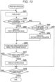
- Fig. 13 is a flowchart illustrating a printing process performed by the image forming apparatus 1. This printing process is executed by the CPU 101 of the controller 100 of the image forming apparatus 1 operating in accordance with an operation program stored in a storage section such as the ROM 102.
- step S01 the feeding of the first sheet is started.
- step S02 it is determined whether it is time to execute the first detection mode.
- the medium detection is executed in the first detection mode in step S03, and then the process proceeds to step S06.
- step S04 it is determined in step S04 whether it is time to execute the second detection mode.
- the medium detection is executed in the second detection mode in step S05, and then the process proceeds to step S06.
- the process proceeds to step S09.
- step S06 a detection result in the first detection mode or the second detection mode is stored and updated in the storage device 110.
- step S07 it is checked whether a sheet type has been changed.
- a notification as illustrated in Fig. 12 which notifies the user that the sheet type has been changed, is displayed in the display section 54 of the operation panel section 50 in step S08.
- the process proceeds to step S09.
- the display to be notified to the user is displayed on the external apparatus such as the information terminal of the user, the server, the cloud, or the like, display data is output via the network.
- the process proceeds to step S09.
- step S09 it is determined whether printing has been completed.
- the process returns to step S01 in order to print the next page.
- the process is ended.
- Fig. 14 is a flowchart illustrating a process of outputting a result of medium detection. This output process is also executed by the CPU 101 of the controller 100 of the image forming apparatus 1 operating in accordance with an operation program stored in a storage section such as the ROM 102.
- step S11 it is determined whether an output request has been provided.
- the output request is provided by operating a predetermined operation button displayed on the display section 54 of the operation panel section 50.
- a request from the external apparatus such as the server or the cloud may be received.
- step S11 When no output request is not provided (NO in step S11), the process waits for an output request.
- the output request is provided (YES in step S11)
- information of a detection result accumulated in the storage device 110 is acquired in step S12.
- step S13 a tray information display window as illustrated in Fig. 9 is created and output.
- the tray information display window is displayed on the display section 54.
- step S14 it is determined whether a confirmation button displayed in the "history" item in the tray information display window illustrated in Fig. 9 has been pressed.
- the process is ended.
- step S14 a tray history window for the corresponding tray as illustrated in Fig. 10 is outputted (displayed) in step S15.
- step S16 it is determined whether the number of changes in the sheet type due to the addition of a sheet is large. For example, a threshold value may be set in advance, and it may be determined that the number is large when the number is equal to or larger than the threshold value.
- step S16 When the number of changes in the sheet type due to the addition of a sheet is large (YES in step S16), a warning is output (displayed) in step S17, and then the process is ended. When the number of changes in the sheet type due to the addition of a sheet is not large (NO in step S16), the process is ended without the warning being output (displayed).
Landscapes
- Physics & Mathematics (AREA)
- General Physics & Mathematics (AREA)
- Engineering & Computer Science (AREA)
- Microelectronics & Electronic Packaging (AREA)
- Control Or Security For Electrophotography (AREA)
- Controlling Sheets Or Webs (AREA)
- Accessory Devices And Overall Control Thereof (AREA)
Abstract
Description
- The present invention relates to an image forming apparatus such as a copying machine, a printer, or a digital multifunction apparatus called a multifunction peripheral (MFP), a method for processing information relating to a recording medium, and a program.
- In general, a user who uses an image forming apparatus wants to select an output sheet by checking what kind of sheet is contained in a sheet feed tray. However, it takes time and effort to go to the apparatus to open and close the sheet feed tray for checking. Meanwhile, by setting sheet information of a sheet in the sheet feed tray, it is possible to check the sheet information without going to the apparatus.
- However, in an office environment or the like in which a plurality of users uses the image forming apparatus, a user may randomly add different types of sheets to the sheet feed tray. When the addition is performed, the sheet information of the sheet feed tray is no longer up to date. In addition, since the latest sheet information is not reported, the user cannot grasp the latest status. Further, since a sheet history of the sheet feed tray is unknown, it is difficult to determine whether the sheet feed tray is available.
- Meanwhile, a medium detection sensor is used as means for detecting the type of sheet. Patent Literature 1 (
Japanese Unexamined Patent Application Publication No. 2022-89505 - Patent Literature 2 (
Japanese Unexamined Patent Application Publication No. 2018-106112 - However,
Patent Literatures Patent Literatures Patent Literatures - An object of the present invention is to provide an image forming apparatus, a method for processing information relating to a recording medium, and a program capable of detecting and outputting the latest information relating to a sheet in a sheet feed tray.
- The above-described object is achieved by the following means.
- (1) An image forming apparatus including:
- a conveyance section that conveys a first recording medium and a second recording medium;
- a recording medium detector that detects information relating to the first recording medium and information relating to the second recording medium; and
- a controller that causes the recording medium detector to detect the information relating to the first recording medium conveyed first by the conveyance section and to detect the information relating to the second recording medium conveyed by the conveyance section after the first recording medium, and outputs the detected information relating to the second recording medium after the first recording medium.
- (2) The image forming apparatus according to the
aforementioned Item 1, further including a holder that is openable and closable with respect to the image forming apparatus and holds the first and second recording media,
in which the controller causes the recording medium detector to detect the information relating to the first recording medium conveyed first by the conveyance section and to detect the information relating to the second recording medium conveyed by the conveyance section after the first recording medium after the holder is closed and before the holder is opened and closed next. - (3) The image forming apparatus according to the
aforementioned Item 1, in which an image forming condition is determined based on the information relating to the first recording medium conveyed first and detected by the recording medium detector. - (4) The image forming apparatus according to the
aforementioned Item 1, in which a time period for which the recording medium detector operates for the detection of the information relating to the second recording medium after the first recording medium is different from a time period for which the recording medium detector operates for the detection of the information relating to the first recording medium. - (5) The image forming apparatus according to the
aforementioned Item 4, in which the recording medium detector determines whether to perform detection of information relating to a recording medium after the first recording medium every time a recording medium is conveyed in accordance with a conveyance speed or every time a predetermined number of recording media are conveyed. - (6) The image forming apparatus according to the
aforementioned Item 1, in which the controller also outputs the information relating to the first recording medium detected by the recording medium detector. - (7) The image forming apparatus according to the
aforementioned Item 1, in which the controller analyzes, based on a change in a result of the detection by the recording medium detector, whether a recording medium has been added. - (8) The image forming apparatus according to the
aforementioned Item 1 or 6, in which the controller outputs notification information when a result of the detection by the recording medium detector changes. - (9) The image forming apparatus according to the
aforementioned Item 8, in which the notification information is a pop-up display on a display screen or a state notification display using an indicator. - (10) The image forming apparatus according to the
aforementioned Item 1, further including:- a holder that is openable and closable with respect to the image forming apparatus and holds the first and second recording media; and
- a storage section that stores and updates an opening/closing history of the holder and a history of detection and update of the information relating to the first and second recording media in association with each other.
- (11) The image forming apparatus according to the
aforementioned Item 1, in which the recording medium detector performs detection of information relating to a recording medium after the first recording medium a plurality of times in a single job. - (12) The image forming apparatus according to the
aforementioned Item 1, further including a holder that is openable and closable with respect to the image forming apparatus and holds the first and second recording media,
in which the recording medium detector performs detection of information relating to a recording medium after the first recording medium a plurality of times until the holder is opened. - (13) The image forming apparatus according to the
aforementioned Item 1, in which the recording medium detector performs detection of information relating to recording media after the first recording medium at least for a second recording medium and a last recording medium in a job. - (14) A method for processing information relating to a recording medium, the method including:
- conveying a first recording medium and a second recording medium;
- detecting information relating to the first recording medium and information relating to the second recording medium; and
- detecting the information relating to the first recording medium conveyed first by the conveying and detecting the information relating to the second recording medium conveyed by the conveying after the first recording medium in the detecting, and outputting the detected information relating to the second recording medium after the first recording medium.
- (15) A program for causing a computer of an image forming apparatus to execute:
- conveying a first recording medium and a second recording medium;
- detecting information relating to the first recording medium and information relating to the second recording medium; and
- detecting the information relating to the first recording medium conveyed first by the conveying and detecting the information relating to the second recording medium conveyed by the conveying after the first recording medium in the detecting, and outputting the detected information relating to the second recording medium after the first recording medium.
- According to the image forming apparatus and the method for processing information relating to a recording medium according to the present invention, information relating to a first recording medium conveyed first is detected, and information relating to a second recording medium conveyed after the first recording medium is detected. Then, since the detected information relating to the second recording medium after the first recording medium is output, a user can know the information relating to the second recording medium newer than the first recording medium conveyed first based on the output information. As a result, even when a recording medium different from the first recording medium is added to a sheet feed tray after the conveyance of the first recording medium, an opportunity to know information relating to recording media after the addition increases. Therefore, a user can grasp the latest sheet information relating to the sheet feed tray, and can easily determine whether the tray can be used.
- According to the program according to the present invention, the program causes the computer of the image forming apparatus to execute conveying a first recording medium and a second recording medium and detecting information relating to the first recording medium and information relating to the second recording medium. Further, the program causes the computer to detect the information relating to the first recording medium conveyed first by the conveying and to detect the information relating to the second recording medium conveyed by the conveying after the first recording medium in the detecting. Then, the program causes the computer to execute outputting the detected information relating to the second recording medium after the first recording medium.
-
-
Fig. 1 is a diagram schematically illustrating a part of a conveyance path for a sheet on which an image is printed in an image forming apparatus; -
Fig. 2 is an explanatory diagram illustrating an optical sensor; -
Fig. 3 is an explanatory diagram illustrating an ultrasonic sensor; -
Fig. 4 is a block diagram illustrating an electrical configuration of the image forming apparatus; -
Fig. 5 is a block diagram illustrating a functional configuration of a controller of the image forming apparatus; -
Fig. 6 is a diagram illustrating an example of a sequence in a first detection mode for detecting information relating to a first recording medium conveyed first and a second detection mode for detecting information relating to a recording medium after the first recording medium; -
Fig. 7 is a diagram illustrating another example of the sequence in the first detection mode and the second detection mode; -
Fig. 8 is a table in which information relating to a recording medium detectable by each recording medium detector is summarized; -
Fig. 9 is a diagram illustrating an example of a display window in a case where results of detecting information relating to recording media in the first detection mode and the second detection mode are displayed; -
Fig. 10 is a diagram illustrating a tray history display window displayed when a confirmation button displayed in a "history" item is pressed in the display window illustrated inFig. 9 ; -
Fig. 11 is a diagram illustrating a warning display screen displayed in a case where the type of sheet held in a holder is changed many times due to addition of a sheet; -
Fig. 12 is a diagram illustrating an example of a hop-up display notifying that the type of sheet has been changed in the middle of a print job; -
Fig. 13 is a flowchart illustrating a printing process performed by the image forming apparatus; and -
Fig. 14 is a flowchart illustrating a process of outputting a result of detection by the image forming apparatus. - Hereinafter, embodiments of the present invention will be described with reference to the drawings.
-
Fig. 1 is a diagram schematically illustrating a part of a conveyance path for a recording medium (hereinafter, the recording medium is also referred to as a sheet or paper) on which an image is printed in animage forming apparatus 1 according to an embodiment of the present invention. - Examples of the
image forming apparatus 1 include, but are not limited to, a copier, a printer, and an MFP which is a digital multifunction apparatus. - In
Fig. 1 , asheet feed section 60 is provided at a lower portion of theimage forming apparatus 1. In thesheet feed section 60, a firstsheet feed tray 60a which is a first-stage sheet feed cassette in an upper stage and a secondsheet feed tray 60b which is a second-stage sheet feed cassette in a lower stage are arranged. Asheet conveyance path 8 is formed in a vertical direction so as to communicate with asheet feed port 8a of the firstsheet feed tray 60a and asheet feed port 8b of the secondsheet feed tray 60b. A sheet fed from thesheet feed port 8a of the firstsheet feed tray 60a or thesheet feed port 8b of the secondsheet feed tray 60b to thesheet conveyance path 8 is conveyed upward in thesheet conveyance path 8 as indicated by an arrow A. The sheet is conveyed to a pair ofskew correction rollers 72 installed at the position of an upper portion of thesheet conveyance path 8 by conveyance rollers (corresponding to a sheet conveyance section) 71a and 71b, and the like. - Further, a manual sheet feed tray (not illustrated) is provided on the opposite side of the first
sheet feed tray 60a with thesheet conveyance path 8 interposed therebetween. A sheet set on the manual sheet feed tray is supplied to thesheet conveyance path 8 via a manualsheet feed port 8c. - Each of the first
sheet feed tray 60a, the secondsheet feed tray 60b, and the manual sheet feed tray corresponds to a holder that holds a sheet. A user can open and close the firstsheet feed tray 60a, the secondsheet feed tray 60b, and the manual sheet feed tray with respect to theimage forming apparatus 1. Opening the firstsheet feed tray 60a and the secondsheet feed tray 60b means removing the first sheet feed tray (sheet feed cassette) 60a and the second sheet feed tray (sheet feed cassette) 60b from a main body of the apparatus for the purpose of replacement of a sheet, addition of a sheet, or the like. Opening the manual sheet feed tray means that a sheet is removed from the manual sheet feed tray to bring the manual sheet feed tray into a non-use state. - On the other hand, closing the first
sheet feed tray 60a and the secondsheet feed tray 60b means attaching the firstsheet feed tray 60a and the secondsheet feed tray 60b to the main body of the apparatus. Closing the manual sheet feed tray means setting a sheet on the manual sheet feed tray and bringing the manual sheet feed tray into a use state. - Further, opening the first
sheet feed tray 60a, the secondsheet feed tray 60b, and the manual sheet feed tray is also referred to as opening thesheet feed ports sheet feed tray 60a, the secondsheet feed tray 60b, and the manual sheet feed tray is also referred to as closing thesheet feed ports sheet feed tray 60a and the secondsheet feed tray 60b can be detected by a sensor (not illustrated). The opening and closing of the manual sheet feed tray can be detected based on whether a sheet is present on the manual sheet feed tray. - The
skew correction rollers 72 are rollers for correcting skew (inclination) of a sheet conveyed in thesheet conveyance path 8. - Between the
sheet feed port 8a of the firstsheet feed tray 60a in the upper stage and theskew correction rollers 72, twomedium detection sensors sheet conveyance path 8. Themedium detection sensors medium detection sensor 91 on the upstream side is an optical sensor that detects light emitted to the sheet. Themedium detection sensor 92 on the downstream side is an ultrasonic sensor that detects an ultrasonic wave output toward the sheet. Theoptical sensor 91 may be disposed on the upstream side, and theultrasonic sensor 92 may be disposed on the downstream side. -
Fig. 2 is an explanatory diagram illustrating theoptical sensor 91. Theoptical sensor 91 includes atransmission light source 91a such as an LED, a reflectionlight source 91b such as an LED, and alight receiving element 91c such as a photodiode. The amount of transmitted light 93, which is light emitted from thetransmission light source 91a and transmitted through a sheet M conveyed in thesheet conveyance path 8, and the amount of reflected light 94, which is light emitted from the reflectionlight source 91b and reflected by the sheet M, are detected as physical property values by thelight receiving element 91c. Then, based on the detected levels of the amount of the transmitted light and the amount of the reflected light, acontroller 100 described later determines the type of the sheet M (a basis weight, an OHP sheet, a recycled sheet, a coated sheet, or the like). Based on this determination, thecontroller 100 detects the type of sheet (sheet type) that is another example of the information relating to the sheet. Theoptical sensor 91 may include a plurality of sensor groups corresponding to red, green, and blue colors, for example. -
Fig. 3 is an explanatory diagram illustrating theultrasonic sensor 92. Theultrasonic sensor 92 includes a pair of anultrasonic transmitter 92a and anultrasonic receiver 92b which are obliquely opposed to each other with thesheet conveyance path 8 interposed therebetween with respect to a direction in which the sheet M passes (seeFig. 1 ). Theultrasonic sensor 92 transmits an ultrasonic wave from theultrasonic transmitter 92a to the passing sheet M, and receives the ultrasonic wave transmitted through the sheet M by theultrasonic receiver 92b. Then, thecontroller 100, which will be described later, detects the type of the sheet M as information relating to the sheet by determining whether the sheet M is a single sheet or a two-ply sheet (envelope) based on the amount of attenuation of the ultrasonic wave by the sheet M. - In the present embodiment, the
image forming apparatus 1 has a user designation mode and an automatic detection mode, and a user can select one of the modes. The user designation mode is a mode in which the user designates a sheet type. When the user designation mode is selected, the detection of a physical property value of a sheet and the determination of the sheet type by themedium detection sensors medium detection sensors -
Fig. 4 is a block diagram illustrating an electrical configuration of theimage forming apparatus 1. As illustrated inFig. 4 , theimage forming apparatus 1 includes thecontroller 100, astorage device 110, animage reading device 120, anoperation panel section 50, animage forming section 10, thesheet feed section 60, theoptical sensor 91, and theultrasonic sensor 92 described above. Theimage forming apparatus 1 further includes aprinter controller 150 and a network interface (network I/F) 160. These components are connected to each other via asystem bus 175. - The
controller 100 includes a central processing unit (CPU) 101, a read only memory (ROM) 102, a static random access memory (S-RAM) 103, a nonvolatile RAM (NV-RAM) 104, and atimepiece IC 105. - The
CPU 101 comprehensively controls the entireimage forming apparatus 1 by executing an operation program stored in theROM 102 or the like. For example, theCPU 101 controls a copy function, a printer function, a scan function, and the like such that the copy function, the printer function, the scan function, and the like are executable. In particular, in this embodiment, theCPU 101 executes detection of physical property values of a sheet based on detection of an amount of light by theoptical sensor 91 and detection of an ultrasonic wave by theultrasonic sensor 92. TheCPU 101 determines the sheet type based on the results of the detection, automatically sets an image forming condition corresponding to the sheet type based on the determination result at the time of printing, and executes printing. TheCPU 101 stores and accumulates the physical property values of the sheet detected by theoptical sensor 91 and theultrasonic sensor 92, the determination result of the sheet type, and the like in thestorage device 110. TheCPU 101 further executes control processing such as output to theoperation panel section 50 or an external apparatus. - The
ROM 102 stores programs to be executed by theCPU 101 and other information. - The S-
RAM 103 serves as a work area for theCPU 101 to execute a program, and temporarily stores the program, data for executing the program, and the like. - The NV-RAM 104 is a nonvolatile memory backed up by a battery. The NV-RAM 104 stores various settings relating to image formation, the number of pixels of a
display section 54, data of various screens to be displayed on thedisplay section 54, and the like. - The
timepiece IC 105 measures time, functions as an internal timer, and measures a processing time. - The
storage device 110 includes a hard disk or the like, and stores programs, various types of data, and the like. In particular, in this embodiment, thestorage device 110 accumulates the results of detecting the sheet physical property values by theoptical sensor 91 and theultrasonic sensor 92, the determination result of the sheet type, a detection history, and the like. - The
image reading device 120 includes a scanner or the like, reads a document set on a platen glass by scanning the document, and converts the read document into image data. - The
operation panel section 50 is used for a user to provide an instruction such as a job to theimage forming apparatus 1 and set various settings. Theoperation panel section 50 includes areset key 51, astart key 52, astop key 53, thedisplay section 54, and atouch panel 55. - The
reset key 51 is used to reset a setting, thestart key 52 is used for a start operation such as scanning, and thestop key 53 is pressed to interrupt the operation. - The
display section 54 includes, for example, a liquid crystal display device, and outputs and displays messages, various operation screens, and the like. Thetouch panel 55 is formed on a screen of thedisplay section 54, and detects a user's touch operation. - The
image forming section 10 prints, on a sheet, a copy image generated from image data of a document read by theimage reading device 120 or from print data transmitted from an externalterminal apparatus 3 or the like. Theimage forming section 10 includes aprint engine 18 and a fixingsection 19 that fixes an image by heating and pressing a sheet on which the image is formed. Theprint engine 18 includes hardware components for image formation, such as a photosensitive drum, a charging device, an exposure device, a developing device, a transfer belt, and a transfer roller. - The network I/F160 functions as communication means that transmits and receives data to and from the external apparatus via a
network 4. Examples of the external apparatus include an external server, a cloud system, a printer driver of an information terminal apparatus of a user, and other image forming apparatuses. -
Fig. 5 is a block diagram illustrating a functional configuration of thecontroller 100. Thecontroller 100 functionally includes amedium detection controller 100a, a sheettype detection controller 100b, animage forming controller 100c, astorage section 100d, anexternal communication controller 100e, and anedge processing section 100f. - The
medium detection controller 100a causes theoptical sensor 91 and theultrasonic sensor 92, which are medium detection sensors, to operate in a first detection mode and a second detection mode, which will be described later, to detect physical properties and the like of a sheet. The sheettype detection controller 100b detects the sheet type based on the results of the detection by theoptical sensor 91 and theultrasonic sensor 92. - The
image forming controller 100c controls theimage forming section 10 under an image forming condition corresponding to each sheet type based on the sheet type detected by the sheettype detection controller 100b, and prints an image on the sheet. - The
storage section 100d temporarily stores the results of detecting the physical property values of the sheet by theoptical sensor 91 and theultrasonic sensor 92, the result of detecting the sheet type by the sheettype detection controller 100b, the detection history, and the like. The information stored in thestorage section 100d is transferred to thestorage device 110 illustrated inFig. 4 , and is accumulated and updated. - The
external communication controller 100e corresponds to the network I/F160 illustrated inFig. 4 . Theexternal communication controller 100e transmits and receives data to and from theexternal apparatus 3 including a terminal apparatus, an external server, another image forming apparatus, or the like. - The
edge processing section 100f has an analyzing function and a learning function, and analyzes a factor of a change in a sheet type and the like using information accumulated in thestorage device 110. - Next, the operation of the
image forming apparatus 1 will be described focusing on control by thecontroller 100. - In this embodiment, in each of the first detection mode and the second detection mode, the
controller 100 causes theoptical sensor 91 and theultrasonic sensor 92 to detect a physical property value and a sheet type of a sheet conveyed in thesheet conveyance path 8. - The first detection mode is executed on the first sheet conveyed first. For the first sheet to be conveyed first, the first
sheet feed tray 60a or the secondsheet feed tray 60b is opened (removed) to perform replacement, supplement, addition, or the like of a sheet. The first sheet is a sheet to be conveyed first after the firstsheet feed tray 60a or the secondsheet feed tray 60b is closed (inserted). Alternatively, in the case of the manual sheet feed tray, the first sheet to be conveyed first is a sheet to be conveyed first after the result of detection as to whether a sheet is present indicates that a sheet is present after a state in which no sheet is present, that is, after the manual sheet feed tray is closed. Alternatively, the first sheet to be conveyed first is a sheet to be conveyed first from a sheet feed port having no sheet type information after sheet type information is reset by turning off and on theimage forming apparatus 1, recovering from sleep, or the like. Alternatively, the first sheet to be conveyed first is a sheet to be conveyed first from a sheet feed port when a medium detection function is switched from OFF to ON. Alternatively, the first sheet to be conveyed first is a sheet to be conveyed first in a print job. - The information relating to the first sheet is undetermined. In the first detection mode, the conveyance is performed at a low speed such that detection results can be reflected in a process condition (image forming condition). Further, in order to perform detailed detection, it is preferable to increase the number of times of reading by the sensors within a sheet surface to improve the accuracy. As a result, the type of the sheet in the sheet feed tray is determined. A fixing temperature and a transfer current are determined under the process condition (image forming condition) corresponding to the determined sheet type. From the next sheet, printing is preferably executed after an appropriate condition for the conveyance speed is selected.
- On the other hand, the second detection mode is a mode in which a physical property value and a sheet type of a sheet other than the first sheet are detected after the sheet type of the first sheet is determined in the first detection mode and before the first
sheet feed tray 60a, the secondsheet feed tray 60b, or the manual sheet feed tray is opened. The detection in the second detection mode may be performed on all sheets except for the first sheet. The detection in the second detection mode may be performed on each plurality of sheets, for example, every other sheet or every fifth sheet, or may be performed at the beginning and end of a job except for the first sheet. - In the second detection mode, the conveyance speed corresponds to the sheet type determined by the detection in the first detection mode. Therefore, depending on the sheet type, the conveyance speed is higher than that in the first detection mode. This shortens a time period from when the sheet reaches the
medium detection sensors skew correction rollers 72. Accordingly, a detection period in the second detection mode is shorter than a detection period in the first detection mode. -
Figs. 6 and7 illustrate different sequence examples for the first detection mode and the second detection mode. InFigs. 6 and7 , for example, the firstsheet feed tray 60a is removed and inserted (opened and closed) as indicated by a "cassette operation" signal. Thereafter, four print jobs (1) to (4) each indicating four sheets are executed as indicated by a "print job" signal. - In both
Figs. 6 and7 , in the first detection mode, the detection is performed on the first sheet fed and conveyed from the firstsheet feed tray 60a after the firstsheet feed tray 60a is removed and inserted (opened and closed), in other words, the first sheet in the print job (1). - On the other hand, in the second detection mode, the detection is performed on all the sheets except for the first sheet in
Fig. 6 . InFig. 7 , the detection is performed on the last sheet in each job.Fig. 6 illustrates that the switching of the sheet type is detected by the detection of the third sheet (the eleventh sheet stacked after the opening and closing of the sheet feed cassette) in the print job (3), andFig. 7 illustrates that the switching of the sheet type is detected by the detection of the last sheet in the print job (3). By such detection, theimage forming apparatus 1 can detect that different types of sheets have been added in the same sheet feed cassette. - In the examples illustrated in
Figs. 6 and7 , the detection is also performed on the first sheet in the first job (print job (4)) after the detection of the switching of the sheet type in the first detection mode. - The
image forming apparatus 1 is configured to be able to perform the detection described with reference toFigs. 6 and7 as the second detection mode, and theimage forming apparatus 1 may select either one of the detection operations according to the performance of theimage forming apparatus 1 and the type of sheet to be conveyed. For example, in a case where the processing performance of theimage forming apparatus 1 is low and the conveyance speed of sheets is high, there is a possibility that various kinds of control during printing may not be performed in time for the detection of each sheet. Therefore, theimage forming apparatus 1 may detect a physical property value and a sheet type of only the last sheet in a job as illustrated inFig. 7 . Theimage forming apparatus 1 may detect not only the last sheet in the job but also every predetermined number of sheets such as every two sheets or every three sheets in the job. - In the present embodiment, information relating to a sheet detected by the
medium detection sensors - Table 1 illustrated in
Fig. 8 summarizes these pieces of information for each detection means. For example, from theoptical sensor 91, information of a sheet type, transmittance, reflectance, a basis weight, a coating agent, a fluorescent agent, a filler, color information, and a pulp material determined from the optical characteristics of a sheet is obtained. Information of the sheet type is obtained from theultrasonic sensor 92. Further, by measuring displacement amounts of the sheet conveyance rollers by a displacement sensor, information of the stiffness of the sheet and the thickness of the sheet can be obtained. Information of the sheet size is obtained from a sheet regulating plate position sensor of each of the sheet feed cassettes 90a and 90b. From a sensor using a CMOS, information of the grain direction, color, smoothness, and pulp material of the sheet is obtained. Information of the moisture and the basis weight is obtained from an electrostatic sensor, and information relating to the resistance is obtained by detecting a transfer current. - As for a sheet type, the
image forming apparatus 1 can determine that a physical property value of a detection target is different by providing a threshold value for the physical property value, for example, transmittance, and can thus detect types of sheets ranging from a thin sheet to a thick sheet. Further, the sheets include a sheet made of at least one of a pulp material, a resin material, and a textile material, an envelope made of at least one of a pulp material, a resin material, and a textile material, and/or an overhead projector (OHP) sheet. - The
controller 100 of theimage forming apparatus 1 has a function of controlling execution of each of the first detection mode and the second detection mode, and outputting a detection result. Examples of an output destination of the detection result include thedisplay section 54 of theoperation panel section 50 of theimage forming apparatus 1, a status display device including an LED and the like, a printer driver of a user's information terminal connected to a network, and a server or cloud system connected to a network. - A display window as illustrated in
Fig. 9 is displayed on a display section of each output destination, for example, thedisplay section 54 of theoperation panel section 50. Also in a case where the detection result is output to the printer driver of the user's information terminal, the server or cloud connected to the network, and the like, a similar display window is displayed on display sections of the information terminal, the server or cloud, and the like. The display of the display window may be performed when a user operates an output button displayed on thedisplay section 54 of theoperation panel section 50. The display of the display window may be periodically performed at predetermined timings. The outputting of the information to the printer driver of the user's information terminal, the server, and the cloud may be performed by a spontaneous output operation from theimage forming apparatus 1, or may be performed in a format in which output requests from the printer driver, the server, and the cloud are received and downloaded. The server and the cloud may collect information from theimage forming apparatus 1 or another image forming apparatus as an information collecting service. - As illustrated in
Fig. 9 , the following items are displayed in the display window for each tray, that is, each of thesheet feed cassettes - In
Fig. 9 , as the trays,trays 1 to 4, a large-capacity tray (LCT), and a manual sheet feed tray are exemplified. - "Sheet size" and "direction" respectively indicate a sheet size and a sheet setting direction. "User designation" indicates which one of the user designation mode and the automatic detection mode has been selected. When the user designation mode is selected, a sheet type designated by a user is displayed.
- In "automatically detected and determined type", information of a sheet type determined after closing of a cassette or for the first sheet by the detection in the first detection mode is displayed. In a case where the user designation mode is selected, since the automatic detection by the
medium detection sensors - In "last sheet type in job", type information of the last sheet in the job at the current time point when continuous printing is performed is displayed. The number of continuous sheets of the same sheet is displayed in "number of continuous sheets of the same sheet". Confirmation buttons are displayed in "history". When a confirmation button is pressed, a history of a tray corresponding to the pressed confirmation button is displayed. This feature will be described later.
- The number of times that it has been determined that a sheet has been added among past 10,000 sheets is displayed in "the number of times of adding a sheet among past 10,000 sheets".
- In "real-time display during printing", the detected latest sheet type and a sheet type detected immediately before are displayed for the tray during printing. In the example illustrated in
Fig. 9 , it is displayed that printing is being performed on a sheet of thetray 1, and both the latest sheet type and the immediately preceding sheet type are plain paper, -
Fig. 10 illustrates a tray history display window displayed when the confirmation button for, for example, thetray 4 displayed in the "history" item in the display window illustrated inFig. 9 is pressed. - The tray history display window indicates details of histories of results of detection by the
medium detection sensors tray 4. The user can view changes in the sheet type for a predetermined number of sheets on thetray 4 in the past. More specifically, the tray history display window indicates that the sheet type changes in the order of plain paper,thick sheet 1, plain paper,thick sheet 1, and plain paper, and indicates the number of printed sheets for each sheet type. The causes of the changes in the sheet type are analyzed by theedge processing section 100f of theimage forming apparatus 1, and results of the analysis are displayed. - For example, when the
tray 4 is opened and closed, it is determined that the user has replaced a sheet, and the change after the opening and closing of the tray is displayed. When theimage forming apparatus 1 is turned off and on and the user replaces a sheet during the turning off, the change after the turning on is displayed. When the sheet type is changed even though no tray is opened and closed or theimage forming apparatus 1 is not turned off and on, it is determined that different types of sheets are mixed, and the change due to the addition of a sheet is displayed. When the number of changes due to the addition of sheets is large, a message describing a disadvantage of adding sheets a large number of times is output as illustrated inFig. 11 . An output destination of the message is thedisplay section 54 of theoperation panel section 50, the printer driver of the user's information terminal, the server or cloud connected to the network, and the like, and a warning is displayed on thedisplay section 54 and display sections of the information terminal, the server or cloud, and the like. In the example illustrated inFig. 11 , it is displayed that the frequency of mixing of different types of sheets in thetray 4 is high, and that it is desirable to insert sheets after removing a remaining sheet for changing to a different type of sheet in order to secure stable print quality and finish. -
Fig. 12 illustrates an example of a hop-up display for informing that the sheet type is changed in the middle of a print job. In this example, it is displayed that the sheet type is changed from plain paper tothick sheet 1 on the 11th and/or 50th sheets in the print job. The hop-up display illustrated inFig. 12 is also output to thedisplay section 54 of theoperation panel section 50, the display device for the printer driver of the user's information terminal, the server or cloud connected to the network, and the like, and is displayed on each display section. - The display is not limited to the pop-up display, and may be a display (state notification display) for notifying the user that the sheet type has been changed by blinking of an indicator such as an LED. Further, even when a print job of the user is not being executed, display for notifying, for example, a user waiting to print in order that a sheet type has been changed during a print job of another user may be performed.
- As described above, by providing notification that a sheet type has been switched during the execution of a print job, the user can grasp the latest sheet type information and history information in the trays, and can appropriately select a tray to be used. Further, in a case where the user does not want to use the results of the automatic detection by the
medium detection sensors thick sheet 1, a sheet is normally conveyed at a conveyance speed corresponding tothick sheet 1, but a user who wants to output quickly may change the setting to plain paper and perform printing. In this case, as in the conventional case, if the sheet type is not the latest and information of a wrong sheet type before switching is output although the sheet type has been switched, the setting may be useless or the setting for plain paper may be inappropriate. For example, whenthick sheet 1 is displayed although the latest sheet type held in the tray is plain paper, a change in the setting to the setting for plain paper by the user is useless. On the other hand, in a case where information of a sheet type which is wrong asthick sheet 1 is output although the latest sheet type in the tray isthick sheet 4, when the setting for plain paper is set, the setting may cause a jam or a failure. Also from such a point of view, since the user can recognize the latest sheet type information and history information, it is possible to properly and safely perform customization. -
Fig. 13 is a flowchart illustrating a printing process performed by theimage forming apparatus 1. This printing process is executed by theCPU 101 of thecontroller 100 of theimage forming apparatus 1 operating in accordance with an operation program stored in a storage section such as theROM 102. - In step S01, the feeding of the first sheet is started. In step S02, it is determined whether it is time to execute the first detection mode. When it is time to execute the first detection mode (YES in step S02), the medium detection is executed in the first detection mode in step S03, and then the process proceeds to step S06. When it is not time to execute the first detection mode (NO in step S02), it is determined in step S04 whether it is time to execute the second detection mode. When it is time to execute the second detection mode (YES in step S04), the medium detection is executed in the second detection mode in step S05, and then the process proceeds to step S06. When it is not time to execute the second detection mode (NO in step S04), the process proceeds to step S09.
- In step S06, a detection result in the first detection mode or the second detection mode is stored and updated in the
storage device 110. - Next, in step S07, it is checked whether a sheet type has been changed. When the sheet type has been changed (YES in step S07), a notification as illustrated in
Fig. 12 , which notifies the user that the sheet type has been changed, is displayed in thedisplay section 54 of theoperation panel section 50 in step S08. Thereafter, the process proceeds to step S09. In a case where the display to be notified to the user is displayed on the external apparatus such as the information terminal of the user, the server, the cloud, or the like, display data is output via the network. Also in a case where the sheet type has not been changed in step S07 (NO in step S07), the process proceeds to step S09. - In step S09, it is determined whether printing has been completed. When the printing has not been completed (NO in step S09), the process returns to step S01 in order to print the next page. When the printing has been completed (YES in step S09), the process is ended.
-
Fig. 14 is a flowchart illustrating a process of outputting a result of medium detection. This output process is also executed by theCPU 101 of thecontroller 100 of theimage forming apparatus 1 operating in accordance with an operation program stored in a storage section such as theROM 102. - In step S11, it is determined whether an output request has been provided. In the case of output (display) to the
operation panel section 50, the output request is provided by operating a predetermined operation button displayed on thedisplay section 54 of theoperation panel section 50. Alternatively, a request from the external apparatus such as the server or the cloud may be received. - When no output request is not provided (NO in step S11), the process waits for an output request. When the output request is provided (YES in step S11), information of a detection result accumulated in the
storage device 110 is acquired in step S12. Thereafter, in step S13, a tray information display window as illustrated inFig. 9 is created and output. In a case where the tray information display window is output to thedisplay section 54 of theoperation panel section 50, the tray information display window is displayed on thedisplay section 54. - Next, in step S14, it is determined whether a confirmation button displayed in the "history" item in the tray information display window illustrated in
Fig. 9 has been pressed. When the button has not been pressed (NO in step S14), the process is ended. When the button has been pressed (YES in step S14), a tray history window for the corresponding tray as illustrated inFig. 10 is outputted (displayed) in step S15. Thereafter, in step S16, it is determined whether the number of changes in the sheet type due to the addition of a sheet is large. For example, a threshold value may be set in advance, and it may be determined that the number is large when the number is equal to or larger than the threshold value. - When the number of changes in the sheet type due to the addition of a sheet is large (YES in step S16), a warning is output (displayed) in step S17, and then the process is ended. When the number of changes in the sheet type due to the addition of a sheet is not large (NO in step S16), the process is ended without the warning being output (displayed).
Claims (15)
- An image forming apparatus (1) comprising:a conveyance section (71a, 71b) that conveys a first recording medium (M) and a second recording medium (M);a recording medium detector (91, 92, 100b) that detects information relating to the first recording medium (M) and information relating to the second recording medium (M); anda controller (100) that causes the recording medium detector (91, 92, 100b) to detect the information relating to the first recording medium (M) conveyed first by the conveyance section (71a, 71b) and to detect the information relating to the second recording medium (M) conveyed by the conveyance section (71a, 71b) after the first recording medium (M), and outputs the detected information relating to the second recording medium (M) after the first recording medium (M).
- The image forming apparatus (1) according to claim 1, further comprising a holder (60a, 60b) that is openable and closable with respect to the image forming apparatus (1) and holds the first and second recording media (M),
wherein the controller (100) causes the recording medium detector (91, 92, 100b) to detect the information relating to the first recording medium (M) conveyed first by the conveyance section (71a, 71b) and to detect the information relating to the second recording medium (M) conveyed by the conveyance section (71a, 71b) after the first recording medium (M) after the holder (60a, 60b) is closed and before the holder (60a, 60b) is opened and closed next. - The image forming apparatus (1) according to claim 1, wherein an image forming condition is determined based on the information relating to the first recording medium (M) conveyed first and detected by the recording medium detector (91, 92, 100b).
- The image forming apparatus (1) according to claim 1, wherein a time period for which the recording medium detector (91, 92, 100b) operates for the detection of the information relating to the second recording medium (M) after the first recording medium (M) is different from a time period for which the recording medium detector (91, 92, 100b) operates for the detection of the information relating to the first recording medium (M).
- The image forming apparatus (1) according to claim 4, wherein the recording medium detector (91, 92, 100b) determines whether to perform detection of information relating to a recording medium (M) after the first recording medium (M) every time a recording medium (M) is conveyed in accordance with a conveyance speed or every time a predetermined number of recording media (M) are conveyed.
- The image forming apparatus (1) according to claim 1, wherein the controller (100) also outputs the information relating to the first recording medium (M) detected by the recording medium detector (91, 92, 100b).
- The image forming apparatus according to claim 1, wherein the controller (100) analyzes, based on a change in a result of the detection by the recording medium detector (91, 92, 100b), whether a recording medium (M) has been added.
- The image forming apparatus (1) according to claim 1 or 6, wherein the controller (100) outputs notification information when a result of the detection by the recording medium detector (91, 92, 100b) changes.
- The image forming apparatus (1) according to claim 8, wherein the notification information is a pop-up display on a display screen or a state notification display using an indicator.
- The image forming apparatus (1) according to claim 1, further comprising:a holder (60a, 60b) that is openable and closable with respect to the image forming apparatus (1) and holds the first and second recording media (M); anda storage section (100d) that stores and updates an opening/closing history of the holder (60a, 60b) and a history of detection and update of the information relating to the first and second recording media (M) in association with each other.
- The image forming apparatus (1) according to claim 1, wherein the recording medium detector (91, 92, 100b) performs detection of information relating to a recording medium (M) after the first recording medium (M) a plurality of times in a single job.
- The image forming apparatus (1) according to claim 1, further comprising a holder (60a, 60b) that is openable and closable with respect to the image forming apparatus and holds the first and second recording media (M),
wherein the recording medium detector (91, 92, 100b) performs detection of information relating to a recording medium (M) after the first recording medium (M) a plurality of times until the holder (60a, 60b) is opened. - The image forming apparatus (1) according to claim 1, wherein the recording medium detector (91, 92, 100b) performs detection of information relating to recording media (M) after the first recording medium (M) at least for a second recording medium (M) and a last recording medium (M) in a job.
- A method for processing information relating to a recording medium, the method comprising:conveying a first recording medium (M) and a second recording medium (M);detecting information relating to the first recording medium (M) and information relating to the second recording medium (M); anddetecting the information relating to the first recording medium (M) conveyed first by the conveying and detecting the information relating to the second recording medium (M) conveyed by the conveying after the first recording medium (M) in the detecting and, outputting the detected information relating to the second recording medium (M) after the first recording medium (M).
- A program for causing a computer (101) of an image forming apparatus (1) to execute:conveying a first recording medium (M) and a second recording medium (M);detecting information relating to the first recording medium (M) and information relating to the second recording medium (M); anddetecting the information relating to the first recording medium (M) conveyed first by the conveying and detecting the information relating to the second recording medium (M) conveyed by the conveying after the first recording medium (M) in the detecting, and outputting the detected information relating to the second recording medium (M) after the first recording medium (M).
Applications Claiming Priority (1)
| Application Number | Priority Date | Filing Date | Title |
|---|---|---|---|
| JP2023010210A JP2024106099A (en) | 2023-01-26 | 2023-01-26 | Image forming apparatus, method and program for processing information on recording medium |
Publications (1)
| Publication Number | Publication Date |
|---|---|
| EP4407376A1 true EP4407376A1 (en) | 2024-07-31 |
Family
ID=89620539
Family Applications (1)
| Application Number | Title | Priority Date | Filing Date |
|---|---|---|---|
| EP24152360.4A Pending EP4407376A1 (en) | 2023-01-26 | 2024-01-17 | Image forming apparatus, method for processing information relating to recording medium, and program |
Country Status (3)
| Country | Link |
|---|---|
| US (1) | US20240255879A1 (en) |
| EP (1) | EP4407376A1 (en) |
| JP (1) | JP2024106099A (en) |
Families Citing this family (1)
| Publication number | Priority date | Publication date | Assignee | Title |
|---|---|---|---|---|
| JP2025004415A (en) * | 2023-06-26 | 2025-01-15 | キヤノン株式会社 | Image processing device, control method for image processing device, and program |
Citations (4)
| Publication number | Priority date | Publication date | Assignee | Title |
|---|---|---|---|---|
| JP2018106112A (en) | 2016-12-28 | 2018-07-05 | キヤノン株式会社 | Image forming apparatus and image forming method |
| US20210364973A1 (en) * | 2020-05-21 | 2021-11-25 | Konica Minolta, Inc. | Recording medium conveyance device, recording medium conveyance method and non-transitory computer-readable recording medium encoded with recording medium conveyance program |
| US20220179347A1 (en) * | 2020-12-04 | 2022-06-09 | Konica Minolta, Inc. | Parameter Determination Apparatus, Image Forming Apparatus, Post-Processing Apparatus, Sheet Feeding Apparatus, And Parameter Determination Method |
| US20220253012A1 (en) * | 2021-02-08 | 2022-08-11 | Seiko Epson Corporation | Transport apparatus |
Family Cites Families (14)
| Publication number | Priority date | Publication date | Assignee | Title |
|---|---|---|---|---|
| US5934140A (en) * | 1996-06-19 | 1999-08-10 | Xerox Corporation | Paper property sensing system |
| KR100381595B1 (en) * | 2001-08-07 | 2003-04-26 | 삼성전자주식회사 | Apparatus for sensing a printing media of printer and sensing method |
| JP2003154735A (en) * | 2001-11-21 | 2003-05-27 | Konica Corp | Print system |
| JP4290131B2 (en) * | 2004-03-31 | 2009-07-01 | キヤノン株式会社 | Recording medium identification device and recording device |
| JP4173495B2 (en) * | 2005-05-27 | 2008-10-29 | 京セラミタ株式会社 | Electronic equipment and monitoring program |
| JP4781191B2 (en) * | 2005-07-29 | 2011-09-28 | キヤノン株式会社 | Image forming apparatus and image forming method |
| US20080265499A1 (en) * | 2007-04-27 | 2008-10-30 | Kabushiki Kaisha Toshiba | Image forming apparatus |
| JP6685792B2 (en) * | 2016-03-25 | 2020-04-22 | キヤノン株式会社 | Image forming device |
| JP2019200397A (en) * | 2018-05-18 | 2019-11-21 | キヤノン株式会社 | Image forming apparatus |
| JP7392460B2 (en) * | 2019-12-24 | 2023-12-06 | コニカミノルタ株式会社 | An image forming apparatus, a method for controlling the image forming apparatus, and a program for causing a computer to execute the control method |
| JP2021117391A (en) * | 2020-01-28 | 2021-08-10 | キヤノン株式会社 | Image forming device |
| JP2022001522A (en) * | 2020-06-22 | 2022-01-06 | コニカミノルタ株式会社 | Recording medium detection device, image formation device, image formation system, and detection method and program for recording medium |
| JP7527870B2 (en) * | 2020-07-09 | 2024-08-05 | キヤノン株式会社 | Image forming system |
| JP7581967B2 (en) * | 2021-03-03 | 2024-11-13 | コニカミノルタ株式会社 | Image forming device |
-
2023
- 2023-01-26 JP JP2023010210A patent/JP2024106099A/en active Pending
-
2024
- 2024-01-17 EP EP24152360.4A patent/EP4407376A1/en active Pending
- 2024-01-26 US US18/423,912 patent/US20240255879A1/en active Pending
Patent Citations (5)
| Publication number | Priority date | Publication date | Assignee | Title |
|---|---|---|---|---|
| JP2018106112A (en) | 2016-12-28 | 2018-07-05 | キヤノン株式会社 | Image forming apparatus and image forming method |
| US20210364973A1 (en) * | 2020-05-21 | 2021-11-25 | Konica Minolta, Inc. | Recording medium conveyance device, recording medium conveyance method and non-transitory computer-readable recording medium encoded with recording medium conveyance program |
| US20220179347A1 (en) * | 2020-12-04 | 2022-06-09 | Konica Minolta, Inc. | Parameter Determination Apparatus, Image Forming Apparatus, Post-Processing Apparatus, Sheet Feeding Apparatus, And Parameter Determination Method |
| JP2022089505A (en) | 2020-12-04 | 2022-06-16 | コニカミノルタ株式会社 | Parameter determination device, image forming device, post-processing device, paper feed device, and parameter determination method |
| US20220253012A1 (en) * | 2021-02-08 | 2022-08-11 | Seiko Epson Corporation | Transport apparatus |
Also Published As
| Publication number | Publication date |
|---|---|
| JP2024106099A (en) | 2024-08-07 |
| US20240255879A1 (en) | 2024-08-01 |
Similar Documents
| Publication | Publication Date | Title |
|---|---|---|
| US10642210B2 (en) | Image forming apparatus | |
| EP1256851A1 (en) | Image forming apparatus capable of determining type of recording sheet to prevent sheet jam | |
| JP2019214185A (en) | Paper kind detector, image formation device, image formation system, and program | |
| US7937005B2 (en) | Image forming apparatus for processing an image in accordance with a sheet size of an image transfer sheet | |
| JP7375975B2 (en) | Image forming apparatus, information processing method and program for recording medium | |
| JP2023038272A (en) | IMAGE FORMING APPARATUS, MEDIUM DETERMINATION METHOD, AND PROGRAM | |
| US20240255879A1 (en) | Image forming apparatus, method for processing information relating to recording medium, and non-transitory recording medium | |
| US11822843B2 (en) | Image forming apparatus, information processing system, method of controlling image forming apparatus, and storage medium | |
| US11402786B2 (en) | Recording medium conveyance device, recording medium conveyance method and non-transitory computer-readable recording medium encoded with recording medium conveyance program | |
| EP4407377A1 (en) | Image forming apparatus, method for controlling conveyance of recording medium, and program | |
| JP7155710B2 (en) | Image forming apparatus, feeding speed setting method and program | |
| JP7655356B2 (en) | Image forming apparatus, method and program for processing information on recording medium | |
| US20110228298A1 (en) | Image forming apparatus, method of controlling image forming apparatus, and storage medium | |
| JP7318786B2 (en) | Image forming apparatus, information processing method and program for recording medium | |
| JP7861391B2 (en) | Image forming apparatus, image forming method, and program | |
| JP2023087812A (en) | Image forming apparatus, image forming method and program | |
| US10791233B2 (en) | Image forming apparatus capable of performing a print job to print an image on a sheet being conveyed | |
| US11244216B2 (en) | Image forming apparatus | |
| JP4152252B2 (en) | Sheet transport device | |
| JP2025165020A (en) | Information processing device | |
| JP2019151041A (en) | Image formation apparatus, sheet type discrimination method and computer program | |
| JP2003316206A (en) | Image forming device | |
| JP2025008688A (en) | Image reader | |
| JP2024128976A (en) | Image reader | |
| JP2021165007A (en) | Image processing device, image processing method |
Legal Events
| Date | Code | Title | Description |
|---|---|---|---|
| PUAI | Public reference made under article 153(3) epc to a published international application that has entered the european phase |
Free format text: ORIGINAL CODE: 0009012 |
|
| STAA | Information on the status of an ep patent application or granted ep patent |
Free format text: STATUS: THE APPLICATION HAS BEEN PUBLISHED |
|
| AK | Designated contracting states |
Kind code of ref document: A1 Designated state(s): AL AT BE BG CH CY CZ DE DK EE ES FI FR GB GR HR HU IE IS IT LI LT LU LV MC ME MK MT NL NO PL PT RO RS SE SI SK SM TR |
|
| STAA | Information on the status of an ep patent application or granted ep patent |
Free format text: STATUS: REQUEST FOR EXAMINATION WAS MADE |
|
| 17P | Request for examination filed |
Effective date: 20250103 |
|
| STAA | Information on the status of an ep patent application or granted ep patent |
Free format text: STATUS: EXAMINATION IS IN PROGRESS |
|
| 17Q | First examination report despatched |
Effective date: 20250220 |
|
| P01 | Opt-out of the competence of the unified patent court (upc) registered |
Free format text: CASE NUMBER: APP_13381/2025 Effective date: 20250318 |