EP4407336A1 - Device and method for 3d real-time medical instrument tracking - Google Patents
Device and method for 3d real-time medical instrument tracking Download PDFInfo
- Publication number
- EP4407336A1 EP4407336A1 EP23153006.4A EP23153006A EP4407336A1 EP 4407336 A1 EP4407336 A1 EP 4407336A1 EP 23153006 A EP23153006 A EP 23153006A EP 4407336 A1 EP4407336 A1 EP 4407336A1
- Authority
- EP
- European Patent Office
- Prior art keywords
- image
- projection
- control unit
- medical instrument
- images
- Prior art date
- Legal status (The legal status is an assumption and is not a legal conclusion. Google has not performed a legal analysis and makes no representation as to the accuracy of the status listed.)
- Pending
Links
- 238000000034 method Methods 0.000 title claims abstract description 52
- 238000003325 tomography Methods 0.000 claims abstract description 45
- 238000001514 detection method Methods 0.000 claims description 12
- 239000013598 vector Substances 0.000 claims description 11
- 230000005284 excitation Effects 0.000 claims description 10
- 238000004590 computer program Methods 0.000 claims description 4
- 230000009286 beneficial effect Effects 0.000 description 13
- 238000003384 imaging method Methods 0.000 description 10
- 230000006870 function Effects 0.000 description 6
- 230000029058 respiratory gaseous exchange Effects 0.000 description 6
- 210000000056 organ Anatomy 0.000 description 5
- 230000008859 change Effects 0.000 description 4
- 239000011159 matrix material Substances 0.000 description 4
- XLYOFNOQVPJJNP-UHFFFAOYSA-N water Substances O XLYOFNOQVPJJNP-UHFFFAOYSA-N 0.000 description 4
- 230000008033 biological extinction Effects 0.000 description 3
- 230000036278 prepulse Effects 0.000 description 3
- 230000009466 transformation Effects 0.000 description 3
- 230000008901 benefit Effects 0.000 description 2
- 239000002872 contrast media Substances 0.000 description 2
- 238000005314 correlation function Methods 0.000 description 2
- 238000010586 diagram Methods 0.000 description 2
- 230000004069 differentiation Effects 0.000 description 2
- 230000000694 effects Effects 0.000 description 2
- 239000000463 material Substances 0.000 description 2
- 229910052751 metal Inorganic materials 0.000 description 2
- 239000002184 metal Substances 0.000 description 2
- 230000001537 neural effect Effects 0.000 description 2
- 238000005457 optimization Methods 0.000 description 2
- RGCLLPNLLBQHPF-HJWRWDBZSA-N phosphamidon Chemical group CCN(CC)C(=O)C(\Cl)=C(/C)OP(=O)(OC)OC RGCLLPNLLBQHPF-HJWRWDBZSA-N 0.000 description 2
- 238000007781 pre-processing Methods 0.000 description 2
- 238000009738 saturating Methods 0.000 description 2
- 230000001629 suppression Effects 0.000 description 2
- 238000012935 Averaging Methods 0.000 description 1
- 229910052688 Gadolinium Inorganic materials 0.000 description 1
- 230000035508 accumulation Effects 0.000 description 1
- 238000009825 accumulation Methods 0.000 description 1
- 239000011149 active material Substances 0.000 description 1
- 238000004458 analytical method Methods 0.000 description 1
- 230000005540 biological transmission Effects 0.000 description 1
- 230000000295 complement effect Effects 0.000 description 1
- 238000012937 correction Methods 0.000 description 1
- 238000006073 displacement reaction Methods 0.000 description 1
- 238000005516 engineering process Methods 0.000 description 1
- 238000011156 evaluation Methods 0.000 description 1
- 230000005281 excited state Effects 0.000 description 1
- 238000001914 filtration Methods 0.000 description 1
- 230000004907 flux Effects 0.000 description 1
- UIWYJDYFSGRHKR-UHFFFAOYSA-N gadolinium atom Chemical compound [Gd] UIWYJDYFSGRHKR-UHFFFAOYSA-N 0.000 description 1
- 238000010191 image analysis Methods 0.000 description 1
- 230000010354 integration Effects 0.000 description 1
- 239000010410 layer Substances 0.000 description 1
- 238000012886 linear function Methods 0.000 description 1
- 238000013507 mapping Methods 0.000 description 1
- 230000010363 phase shift Effects 0.000 description 1
- 239000004033 plastic Substances 0.000 description 1
- 229920003023 plastic Polymers 0.000 description 1
- 230000008569 process Effects 0.000 description 1
- 230000004044 response Effects 0.000 description 1
- 239000002356 single layer Substances 0.000 description 1
- 230000003595 spectral effect Effects 0.000 description 1
- 230000003068 static effect Effects 0.000 description 1
- 230000000007 visual effect Effects 0.000 description 1
- 238000004804 winding Methods 0.000 description 1
Images


Classifications
-
- G—PHYSICS
- G01—MEASURING; TESTING
- G01R—MEASURING ELECTRIC VARIABLES; MEASURING MAGNETIC VARIABLES
- G01R33/00—Arrangements or instruments for measuring magnetic variables
- G01R33/20—Arrangements or instruments for measuring magnetic variables involving magnetic resonance
- G01R33/44—Arrangements or instruments for measuring magnetic variables involving magnetic resonance using nuclear magnetic resonance [NMR]
- G01R33/48—NMR imaging systems
- G01R33/54—Signal processing systems, e.g. using pulse sequences ; Generation or control of pulse sequences; Operator console
- G01R33/56—Image enhancement or correction, e.g. subtraction or averaging techniques, e.g. improvement of signal-to-noise ratio and resolution
- G01R33/5608—Data processing and visualization specially adapted for MR, e.g. for feature analysis and pattern recognition on the basis of measured MR data, segmentation of measured MR data, edge contour detection on the basis of measured MR data, for enhancing measured MR data in terms of signal-to-noise ratio by means of noise filtering or apodization, for enhancing measured MR data in terms of resolution by means for deblurring, windowing, zero filling, or generation of gray-scaled images, colour-coded images or images displaying vectors instead of pixels
-
- A—HUMAN NECESSITIES
- A61—MEDICAL OR VETERINARY SCIENCE; HYGIENE
- A61B—DIAGNOSIS; SURGERY; IDENTIFICATION
- A61B34/00—Computer-aided surgery; Manipulators or robots specially adapted for use in surgery
- A61B34/20—Surgical navigation systems; Devices for tracking or guiding surgical instruments, e.g. for frameless stereotaxis
-
- A—HUMAN NECESSITIES
- A61—MEDICAL OR VETERINARY SCIENCE; HYGIENE
- A61B—DIAGNOSIS; SURGERY; IDENTIFICATION
- A61B34/00—Computer-aided surgery; Manipulators or robots specially adapted for use in surgery
- A61B34/25—User interfaces for surgical systems
-
- A—HUMAN NECESSITIES
- A61—MEDICAL OR VETERINARY SCIENCE; HYGIENE
- A61B—DIAGNOSIS; SURGERY; IDENTIFICATION
- A61B5/00—Measuring for diagnostic purposes; Identification of persons
- A61B5/05—Detecting, measuring or recording for diagnosis by means of electric currents or magnetic fields; Measuring using microwaves or radio waves
- A61B5/055—Detecting, measuring or recording for diagnosis by means of electric currents or magnetic fields; Measuring using microwaves or radio waves involving electronic [EMR] or nuclear [NMR] magnetic resonance, e.g. magnetic resonance imaging
-
- G—PHYSICS
- G01—MEASURING; TESTING
- G01R—MEASURING ELECTRIC VARIABLES; MEASURING MAGNETIC VARIABLES
- G01R33/00—Arrangements or instruments for measuring magnetic variables
- G01R33/20—Arrangements or instruments for measuring magnetic variables involving magnetic resonance
- G01R33/28—Details of apparatus provided for in groups G01R33/44 - G01R33/64
- G01R33/285—Invasive instruments, e.g. catheters or biopsy needles, specially adapted for tracking, guiding or visualization by NMR
-
- G—PHYSICS
- G01—MEASURING; TESTING
- G01R—MEASURING ELECTRIC VARIABLES; MEASURING MAGNETIC VARIABLES
- G01R33/00—Arrangements or instruments for measuring magnetic variables
- G01R33/20—Arrangements or instruments for measuring magnetic variables involving magnetic resonance
- G01R33/44—Arrangements or instruments for measuring magnetic variables involving magnetic resonance using nuclear magnetic resonance [NMR]
- G01R33/48—NMR imaging systems
- G01R33/54—Signal processing systems, e.g. using pulse sequences ; Generation or control of pulse sequences; Operator console
- G01R33/56—Image enhancement or correction, e.g. subtraction or averaging techniques, e.g. improvement of signal-to-noise ratio and resolution
- G01R33/5607—Image enhancement or correction, e.g. subtraction or averaging techniques, e.g. improvement of signal-to-noise ratio and resolution by reducing the NMR signal of a particular spin species, e.g. of a chemical species for fat suppression, or of a moving spin species for black-blood imaging
-
- A—HUMAN NECESSITIES
- A61—MEDICAL OR VETERINARY SCIENCE; HYGIENE
- A61B—DIAGNOSIS; SURGERY; IDENTIFICATION
- A61B34/00—Computer-aided surgery; Manipulators or robots specially adapted for use in surgery
- A61B34/20—Surgical navigation systems; Devices for tracking or guiding surgical instruments, e.g. for frameless stereotaxis
- A61B2034/2046—Tracking techniques
-
- A—HUMAN NECESSITIES
- A61—MEDICAL OR VETERINARY SCIENCE; HYGIENE
- A61B—DIAGNOSIS; SURGERY; IDENTIFICATION
- A61B34/00—Computer-aided surgery; Manipulators or robots specially adapted for use in surgery
- A61B34/20—Surgical navigation systems; Devices for tracking or guiding surgical instruments, e.g. for frameless stereotaxis
- A61B2034/2046—Tracking techniques
- A61B2034/2051—Electromagnetic tracking systems
-
- A—HUMAN NECESSITIES
- A61—MEDICAL OR VETERINARY SCIENCE; HYGIENE
- A61B—DIAGNOSIS; SURGERY; IDENTIFICATION
- A61B34/00—Computer-aided surgery; Manipulators or robots specially adapted for use in surgery
- A61B34/20—Surgical navigation systems; Devices for tracking or guiding surgical instruments, e.g. for frameless stereotaxis
- A61B2034/2046—Tracking techniques
- A61B2034/2065—Tracking using image or pattern recognition
Definitions
- the invention is related to a method and a magnetic resonance tomography unit for tracking a medical instrument.
- a tracking volume is defined enclosing a predefined trajectory of the medical instrument. Images of the tracking volume in presence of the medical instrument are acquired with the magnetic resonance tomography unit and coordinates of the medical instrument are extracted and output on a display.
- Magnetic computer tomographs are imaging facilities, which for imaging an examination object align nuclear spins of the examination object with a strong external magnetic field and excite them with a magnetic alternating field for precession about this alignment. The precession or return of the spins from this excited state back into a state with lower energy in its turn creates as a response a magnetic alternating field, which is received via antennas.
- a spatial encoding is impressed on the signals with the aid of magnetic gradient fields, which subsequently makes it possible to assign the received signal to a volume element.
- the received signal is then evaluated and a 3D image representation of the examination object is provided.
- the object is achieved by an inventive method for operation of a magnetic resonance tomograph as claimed in claim 1 and by an inventive magnetic resonance tomograph as claimed in claim 12.
- the method according to the invention is a method for tracking a medical instrument with a magnetic resonance tomograph in real time.
- Real time means in his context that the image repetition rate is high enough such that an operator can track and control the movement of the medical instrument, e.g. with an image repetition rate higher than 1 f/s (frames per second), 5 f/s or 10 f/s.
- the method is executed by a magnetic resonance tomograph which comprises a control unit for controlling all sub-systems like gradient generation and RF transmission and reception for image acquisition and also for the image reconstruction, analysis and display.
- the control unit may also be separated in different sub-systems for each task.
- a tracking volume is defined or determined by the control unit.
- a tracking volume is defined as a volume in the field of view of the magnetic resonance tomograph which encloses a predefined trajectory of the medical instrument.
- the predefined trajectory may be entered by an operator or transferred as data from a treatment planning system.
- the trajectory describes a path along which the medical instrument shall be moved.
- the tracking volume may e.g. be determined by a cuboid wherein the surfaces are determined by six planes orthogonal to the axes of a coordinate system in which the trajectory is defined. The coordinates where the planes intersect with the axes are the minimum and the maximum value of the coordinate of the trajectory along each axe. Other non-orthogonal coordinate systems and tracking volumes may also be considered, wherein the trajectory is included by the tracking volume.
- the tracking volume may also be changed during execution of the method, which might be considered as starting with a new instance of the method.
- a first 2D projection image of the tracking volume is acquired by the control unit in presence of the medical instrument with the magnetic resonance tomography unit.
- the tracking volume is, as explained before, a three-dimensional volume which extends in all three directions of space.
- the tracking volume has an extension in each dimension of a multiple of r.
- a 2D projection image of the tracking volume is a 2D image, i.e. an array of pixels arranged in a matrix in a 2D surface, preferably a plane or a piece of a plane. The plane could be considered as a section plane through the tracking volume.
- Each pixel is assigned a value.
- this value is not assigned to the magnetic resonance signal of a single volume element or voxel in the tracking volume, but derives from a plurality of voxels arranged along a line through the pixel in a projection direction.
- the projection direction is perpendicular to the 2D surface.
- the values of each voxel along the line sum up to a value which is assigned to the pixel. This is similar to a 2D X-ray image, wherein the attenuation factors of all volume elements along the x-ray beam direction sum up to the pixel value in the x-ray image.
- the contrast of the image acquisition of the first 2D projection image may be enhanced by contrast improving steps like partial saturation pre-pulses.
- a second 2D projection image is acquired.
- a first projection direction or projection vector for the first 2D projection image is different from a second projection vector of the second 2D projection image.
- the first projection vector and the second projection vector enclose an angle larger than 30 degrees or 60 degrees, preferably equal to 90 degrees, such that the 2D projection images may be used as 2D maps showing the tracking volume from different viewing directions, as will be discussed later.
- the projection vectors are orthogonal to planes of the 2D projection images.
- a first reference 2D image is determined by the control unit.
- a reference 2D image is an image similar to the first and second 2D projection image. It shows the tracking volume under the same viewing direction or projection direction.
- a reference 2D image depicts features of the patient in the tracking image, which do not change with the movement of the medical instrument.
- a reference 2D image can be derived from a separate image acquisition in absence of the medical instrument.
- a reference 2D image may be computed by the control unit from previous first and second 2D images, eliminating the variable effects caused by the moving medical instrument.
- a second reference 2D image is determined by the control unit, having the same viewing direction or projection direction as the second 2D projection image.
- a background is suppressed or removed from the first 2D image as a function of the first reference 2D image by the control unit.
- the background may be suppressed by a subtraction of the pixel values of the first 2D image minus the first 2D reference image.
- the values for the scaling function may be determined by an optimization problem, e.g. minimizing the sum of the square values of the difference of the image pixel values (LSQR).
- the control unit determines a first set of coordinates of the medical instrument from the first 2D image after background suppression.
- major contrast shall be caused by the medical device.
- an algorithm for detecting areas of high contrast may therefore be applied to determine the contour of the medical instrument.
- Other image analysis algorithms may be used, as well as neuronal networks and/or AI trained with images of the medical instrument at known coordinates. With the coordinates of the contour in the image, coordinates of the medical instrument in the plane of the image may be determined using the mapping relation of the imaging process of the magnetic resonance tomograph.
- a background is suppressed or removed from the second 2D image as a function of the second reference 2D image by the control unit and a second set of coordinates in the image plane of the second 2D reference image or the second 2D image of the medical instrument is determined from the second 2D image by the control unit.
- At least two set of coordinates in two planes at different orientations in space are known, which define a position of the medical instrument, i.e. at least one point like the tip, in three dimensional space.
- the 3D coordinate is extracted from the two sets of coordinates in the two planes.
- the two coordinate sets in the two planes define a position in 3D space, which is derived by coordinate transformation by the control unit.
- the method allows a quick detection and 3D tracking of the medical instrument with the magnetic resonance tomograph.
- the magnetic resonance tomograph configured to execute the method shares the benefits of the method according to the invention.
- the method further comprises the step of outputting the 3D position of the medical instrument to a user.
- the 3D position may e.g. be depicted in a 3D- rendered image, a virtual reality device or by a plurality of 2D images from different view aspects. It is also conceivable that the 3D position is output in numerical values or coordinates.
- the visual display of the coordinates eases in a beneficial way the navigation of the medical instrument by a user.
- the control unit determines the first reference 2D image from a plurality of first 2D projection images and/or determines the second reference 2D image from a plurality of second 2D projection images.
- the reference 2D images shall depict features in the tracking volume, which do not change with the movement of the medical instrument and may be subtracted as background from the 2D projection images to ease detection of the medical instruments.
- Such reference 2D images may be derived from a plurality of 2D projection images by selecting or filtering constant image content. As a most simple way, a plurality of 2D projection images could be averaged, such that constant content adds up while changing content is reduced. Median functions could be applied, which identify and suppress pixels changing in consequent 2d projections. The determination may also depend on the signal generated by the medical device. E.g. a metallic instrument causes extinction of the MR signal in a surrounding volume, while a catheter filled with contrast agent like a Gadolinium solution may cause a strong positive signal.
- generating the reference 2D images from 2D projection images allow a continuous update of the background signal and saves time for separate acquisition of reference 2D images.
- the method further comprises the step of acquiring a 2D slice comprising the medical instrument by the magnetic resonance tomograph.
- the control unit determines the position of the 2D slice in dependence of the first set of coordinates and/or second set of coordinates.
- the control unit may e.g. determine a 3D coordinate in space as explained before and then determine a plane which includes the 3D coordinates of the medical instrument, which is given by e.g. the coordinate of the tip of the medical instrument and the direction of extension.
- the slice to be imaged is the cross section of this plane and the field of view.
- the acquisition of the slice allows to show the user the medical instrument together with the environment in the body of a patient.
- the control unit determines the first reference 2D image by acquiring a third 2D projection image of the tracking volume in absence of the medical instrument in the tracking volume with the magnetic resonance tomography unit and/or determines the second reference 2D image by acquiring a fourth 2D projection image of the tracking volume in absence of the medical instrument in the tracking volume with the magnetic resonance tomography unit.
- the reference 2D images are acquired by the control units with separate image acquisitions of 2D projection images. These reference 2D images are acquired when the medical instrument is not present in the tracking volume, such that no signals caused by the medical instrument are part of the reference 2D images.
- the reference 2D images may e.g. be acquired in advance to the intervention.
- the acquisition may be performed using a fat suppressing sequence e.g. a Dixon sequence or a sequence using a fat saturating pre-pulse or a water selective exciting pulse. Also all other image improving steps explained before may be applied.
- the steps of acquiring a 2D projection image of the tracking volume comprises the step of exciting the spins in the tracking volume by an excitation pulse at the same time with the same excitation pulse.
- This might be caused with a narrow-band excitation pulse at Larmor frequency in a homogeneous B0 magnetic field.
- a broadband excitation pulse as a magnetic gradient field is applied at the same time.
- the bandwidth of the pulse is determined by the strength of the gradient and the dimension of the tracking volume along the axis of the gradient. This selection of a single slice limited to the tracking volume suppresses signals from outside the tracking volume at least in direction of the gradient axis.
- a 2D encoding scheme e.g. phase encoding
- phase encoding By applying only encoding in two dimensions, e.g. x- and y-axis, there is no differentiation for the MR signals of the volume elements along the third axis and the MR signals of the volume elements are summed up.
- the complete tracking volume can be acquired in a single acquisition in a 2D projection image.
- the defined tracking volume is divided by the control unit into a stack of slices.
- such slices could e.g. provided by splitting the cuboid by a plurality of planes parallel to one of the surfaces of the cuboid.
- the planes could be preferably positioned equidistant, i.e. each slice having a same thickness or dimension along the normal vector of the planes.
- the slices may also be maps of the ideal planar planes described before, distorted by the magnetic resonance tomographs imperfection.
- the slices are arranged along an axe of the image acquisition, such that in the hereinafter described step of projection maybe performed as easy as possible.
- the magnet resonance tomograph acquires a first 1D projection for each slice.
- the spins to be detected in the slices are excited by an excitation pulse with a magnetic gradient applied in orthogonal direction to the slice.
- a 1D projection is an image acquisition, wherein an encoding for spatial resolution is only applied in one dimension.
- an encoding is provided only along one axis.
- the signal generated and acquired for any spot along this axis represents an integral of the signals of all volume elements of the slice along a projection line through the axis at this spot and perpendicular to the axis in the plane of the slice.
- the value generated for each spot represents the integral of the spins along the projection line, similar to the electron density for of an x-ray image.
- the generated 1D projections for all slices are combined to a 2D projection image by the control unit.
- the lines of the 1D projections are aligned in parallel, thereby providing an image of the stack of slices in a perspective parallel to the slices and perpendicular to the axis.
- a second 1D projection for each slice is acquired by the magnetic resonance tomograph in a second projection direction, wherein the first projection direction and the second projection direction enclose an angle larger than 45 degrees, 60 degrees or 80 degrees, preferably of 90 degrees.
- the stack of second 1D projections is combined by the control unit to a second 2D projection image.
- the perspective of the second reference image is turned relative to the first reference image around the axis by the angle, preferably by 90 degrees to provide a view from two different sides of a cube which eases the navigation of the medical instrument by a user.
- the method further comprising the step of acquiring an MR image for a 2D slice comprising the medical instrument, wherein the control unit determines the position of the 2D slice in dependence of the first set of coordinates and/or second set of coordinates. As the position of the medical instrument has been determined, the control unit calculates a plane with position and orientation, such that the medical instrument lies in the plane/slice. The control unit acquires then a 2D image of the slice with the magnetic resonance unit and preferably presents the image to an operator.
- the method allows to provide 2D images with the medical instrument updated with a high frequency.
- the steps of determining reference 2D images are repeated for different positions of a patient.
- the position is not limited to the externally visible position of the patient, but particularly comprises a position of organs within the tracking volume.
- the position of organs may change during breathing and/or heartbeat.
- the different positions may include different phases of heartbeat or breathing.
- a plurality of first reference 2D images and second reference 2D images are generated by the control unit. As the 2D projection images are acquired at different positions, each of the plurality of the first reference images and of the second reference images represent a different breathing position.
- a library of reference images is prepared for a plurality, or preferably for all breathing and/or heartbeat positions.
- background information is provided for different breathing positions which enables tracking at any time.
- the control unit selects the first reference 2D image of the plurality of first reference 2D images, which is most similar to the first 2D projection image.
- the difference between the reference image and a target image with the medical instrument for tracking is least.
- the reference image from the plurality of reference 2D images may be chosen, for which a sum of the squares of the difference of the pixel values between reference image and the target images is minimal.
- a correlation function provides the highest value for the two images.
- the peak detection selection of the reference with the least difference eases detection of the medical instrument.
- a fat suppressing sequence is used for acquisition.
- Such sequence may e.g. be a Dixon sequence or a sequence using a fat saturating pre-pulse or a water selective exciting pulse.
- fat accumulations along the projection path may dominate result of the projection.
- a fat suppression technology may be used to reduce the fat signal and make the medical instrument visible in the projection.
- a peak detection algorithm is applied in the steps determining a first set of coordinates of the medical instrument from the first 2D image and /or determining a second set of coordinates of the medical instrument from the second 2D image.
- Such peak detection algorithm may use algorithms for e.g. a simple high-pass filter for increasing the contrast of a border, border detection or even a neuronal network trained with different images of the medical instrument at different positions. Parametrized models of the medical instruments may also be used in an optimization with LSR to determine the position of the medical instrument.
- the peak detection is applied to a 2D projection image after removing the background.
- the peak detection algorithms speed up and make the detection of the medical instrument more reliable.
- the medical instrument is a catheter.
- a catheter may differ in the way it is imaged by the magnetic resonance tomography unit. Instead of extinction of the signal by metal, a contrast agent in the catheter may provide a strong signal. In a beneficial way, the method is independent on the kind of signal.
- the tomography unit according to the invention is configured to perform the method according to the invention.
- the magnetic resonance tomography unit may be enabled to perform the method by loading a computer program product from a storage media into a memory of the control unit and executing the program.
- Fig. 1 shows a schematic diagram of a form of embodiment of an inventive magnetic resonance tomography unit 1.
- the magnet unit 10 has a field magnet 11, which generates a static magnetic field B0 for alignment of nuclear spins of samples or patients 100 in a recording region.
- the recording region is arranged in a patient tunnel 16, which extends in a longitudinal direction 2 through the magnet unit 10.
- a patient 100 may be moved by means of the patient couch 30 and the drive unit 36 of the patient couch 30 into the recording region.
- the field magnet 11 involves a superconducting magnet, which can provide magnetic fields with a magnetic flux density of up to 3T, with the very latest devices of even more. For lower field strengths however permanent magnets or electromagnets with normally conducting coils can be employed.
- the magnet unit 10 furthermore has gradient coils 12, which are designed, for spatial differentiation of the recorded imaging regions in the examination volume, to superimpose variable magnetic fields in three spatial directions on the magnetic field B0.
- the gradient coils 12 are usually coils made of normally conducting wires, which can generate fields orthogonal to each other in the examination volume.
- the magnet unit 10 likewise has a body coil 14, which is designed to radiate a radio-frequency signal supplied via a signal line into the examination volume and to receive resonant signals emitted by the patient 100 and output them via a signal line 33.
- the body coil 14 is replaced, for sending out the radio-frequency signals and/or receiving them, by the local coil 50, which is arranged in the patient tunnel 16 close to the patient 100. It is also conceivable however for the local coil 50 to be designed for sending and receiving and therefore a body coil 14 can be omitted.
- a control unit 20 supplies the magnet unit 10 with the various signals for the gradient coils 12 and the body coil 14 and evaluates the received signals.
- a magnetic resonance tomography unit controller 23 coordinates the subunits in this case.
- control unit 20 has a gradient control 21, which is designed to supply the gradient coils 12 via supply leads with variable currents, which provide the desired gradient fields coordinated in time in the examination volume.
- the control unit 20 furthermore has radio-frequency unit 22, which is designed to generate a radio-frequency pulse with a predetermined timing curve, amplitude and spectral power distribution to excite a magnetic resonance of the nuclear spins in the patient 100.
- radio-frequency unit 22 is designed to generate a radio-frequency pulse with a predetermined timing curve, amplitude and spectral power distribution to excite a magnetic resonance of the nuclear spins in the patient 100.
- pulse powers in the range of kilowatts can be achieved.
- the individual units are linked to one another via a signal bus 25.
- the radio-frequency signal generated by the radio-frequency unit 22 is conveyed via a signal connection to the body coil 14 and emitted into the body of the patient 100, in order to excite the nuclear spins there. Also conceivable is however an emission of the radio-frequency signal via one or more coil windings of the local coil 50.
- the local coil 50 then preferably receives a magnetic resonance signal from the body of the patient 100 since, because of the short distance, the signal-to-noise ratio (SNR) of the local coils 50 is better than a receipt by the body coil 14.
- the MR signal received by the local coil 50 is preprocessed in the local coil 50 and forwarded to the radio-frequency unit 22 of the magnetic resonance tomography unit 1 for evaluation and image acquisition.
- the signal connection between local coil 50 and magnetic resonance tomography unit 1 may be via a signal line 33 or wireless.
- the medical instrument 60 may be guided by an operator using the imaging capabilities of the magnetic resonance tomography unit 1 with the method according to the invention as discussed below.
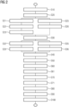
- Fig. 2 shows a flow chart of an embodiment of the method for tracking a medical instrument according to the invention.
- the method is executed by a magnetic resonance tomography unit comprising 1 a control unit 20 which is configured to perform the steps of an image acquisition with the magnetic resonance tomography unit 1 and in particular the steps of the method according to the invention.
- a tracking volume 70 is defined by the control unit 20, which encloses a predefined trajectory 71.
- the trajectory 71 may e.g. be derived from a 3D model of the patient 100 by an operator.
- the trajectory 71 may be a linear path between an entrance point and a target destination in the body of a patient 100.
- the trajectory 71 may also be curved, e.g., in case the medical instrument is a catheter, and it is delimited by a vessel of a patient.
- a tracking volume 70 may e.g. be defined by a cuboid with the coordinates of the corners given by the minima and maxima of the x, y, z- coordinates of all points along the trajectory 71.
- a first 2D projection image of the tracking volume in presence of the medical instrument is acquired by the control unit 20 using the magnetic resonance tomography unit 1.
- a 2D projection image is an image, which depicts a 3D volume by an 2D image in a plane or piece of a plane by a projection of volume elements along a projection vector or projection direction onto the plane.
- a 2D projection image may e.g. be acquired by first providing 1D projections of multiple slices of a volume and combining then these 1D projections to a 2D projection image.
- the tracking volume 70 is therefore divided into a stack of slices 72 by the control unit 20.
- a slice 72 is an essentially two-dimensional layer of volume elements to be imaged arranged in preferably a plane. The plane may be distorted or warped by non-linearities of the gradient system.
- the stack of slices 72 may e.g. be arranged along the longitudinal direction 2 along the z-axis parallel to the B0 magnetic field, wherein the planes of the slices 72 are perpendicular to the z-axis. But any other orientation of the stack is considerable, e.g. along x-axis or y-axis or any linear combination thereof.
- the slices 72 of a stack are of equal thickness and/or the planes are arranged at equal distance and fully cover the tracking volume 70 such that there is no place inside the tracking volume 70 which is not included when acquiring MR data for all volume elements 73 of the slices 72.
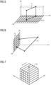
- Fig. 3 such an exemplary stack of slices 72 is shown.
- the slices are arranged in parallel to the x-y-plane of the coordinate system and the stack of slices 72 is arranged along the z-direction. Only a single volume element 73 is shown, but each of the slices is fully covered by a matrix of such volume elements 73.
- control unit 20 acquires a first 1D projection for each slice 72, using the magnetic resonance tomography unit 1.
- Such a 1D-projection is shown exemplary in Fig. 4 for a single slice 72.
- the slice 72 is arranged parallel to the x-y-plane.
- Such a slice 72 can e.g. be captured by sending an excitation pulse for a narrow frequency band while a z-gradient magnetic field is applied by the control unit 20 using the gradient coils.
- the position along the z-axis is defined by the center frequency of the pulse while thickness of the slice 72 along the z-axis is defined by the bandwidth of the pulse.
- the stack of first 1D projections is combined by the control unit 20 to a first 2D reference image.
- the resulting image lines 74 in are arranged in parallel to each other in the x-z-plane such that the pixel elements of each image line 74 in x-direction together with the neighboring pixels of the other slices 72 complement to a two-dimensional image in the x-z-plane.
- the image provides x-z coordinates for any object in the slices 74 above the x-z-plane independent from the y coordinate in the slices 74 by the projection along the y-axis.
- steps S32 and S33 the steps S22 and S23 are repeated with another coordinate system, e.g. the roles of x and y axis may be swapped such that the slices are projected along the x-axis onto an image line 74 extending along the y-axis, as shown in Fig. 6 .
- This is equivalent to a rotation of the coordinate system around the z-axis by 90 degrees.
- the idea behind is that the projections in two different directions each provide a pair of two coordinates for each point projected. If the projection directions are not parallel and preferably include an angle larger than 45 degrees or 60 degrees, in particular equal to 90 degrees, the two pairs of two-dimensional coordinates in the projections may be used to determine a three-dimensional coordinate of each point projected.
- a 2D projection image may also be acquired with 2D encoding.
- the tracking volume 70 may also be seen as a single slice, which is subdivided in columns in the x-y-axis extending in z-direction through the slice.
- a single slice could be defined in the y-z-plane with columns extending in x-direction.
- the excitation may be limited to the thickness of the single slice by applying a broadband excitation pulse, wherein the bandwidth is determined by the applied magnetic gradient in direction of the thickness of the slice and the thickness.
- the 2D projection is then acquired by reading out the MR signals for the tracking volume by applying a 2D encoding in Steps S26, S36.
- the encoding scheme could be e.g. a 2D phase encoding.
- a second 2D projection image is acquired in steps S35, S36 wherein at least the step 36 differs from the step S26 by the plane in which the 2D-encoding is provided.
- the resulting two 2D projection images show the tracking volume from two aspect directions which enclose an angle larger than 30 degrees, 60 degrees, preferably equal to 90 degrees.
- the 2D projection images of Fig. 5 provides x-z-coordinates and Fig. 6 y-z-coordinates such that for an object, which can be identified unambiguously in both projections, the coordinates x, y and z are directly given.
- a coordinate transformation by a matrix may be necessary.
- a first reference 2D image is determined by the control unit 20. There are different options how the control unit 20 may perform this step.
- a separate 2D projection image may be acquired as explained before in regard to steps S20 and S30, but in absence of the medical instrument, such that the reference 2D image only depicts the patient 100.
- control unit 20 provides a library of reference 2D images by acquiring a series of 2D projection images at different positions of the patient 100.
- the position is not limited to the body surface of the patient 100, but is in particular related to the organs of the patient 100 in the tracking volume, which may change their position, e.g. as the patient breaths or with the heart beat.
- the library or atlas of 2D reference images may cover different phases of the heart beat and/or breathing cycle.
- control unit 20 makes use of already acquired 2D projection images for determining a background image.
- the control unit may filter out constant parts of the 2D projection images to retrieve a background. This could e.g. be achieved by averaging a plurality of images or applying a median function. Also a filter could be applied which reflects the way how the medical instrument is imaged by the magnetic resonance tomography unit 1, e.g. signal extinction.
- step S50 the control unit 20 determines a second reference 2D image or a library of reference 2D images. The difference is the projection direction or view angle. While the first reference 2D image in step S40 depicts the tracking volume 70 at the same view angle and provides a 2D projection image at the same projection direction than the first 2D projection image, the second 2D reference image depicts the tracking volume 70 at the same view angle than the second 2D reference image.
- control unit 70 suppresses the background from the first 2D projection image as a function of the first reference 2D image.
- the control unit 70 could e.g. subtract the pixel values of the reference 2D image from the 2D projection image.
- the reference 2D image could be scaled or distorted before to adjust variations in the image acquisition.
- the preprocessing could be parametrized and the parameters could be optimized for minimum energy of the resulting differential image.
- control unit may first select a reference 2D image for background removal from the library which is next to the first 2D projection image. Next may be measured by a metric which e.g. could be provided by a correlation function between 2D projection image and reference 2D image or a minimum energy of a difference image.
- step S61 a first set of coordinates of the medical instrument from the first 2D image by the control unit.
- the remaining 2D differential image basically shows the medical instrument 60 or artefacts caused by the medical instrument.
- a pixel belonging to the medical instrument 60 may be e.g. detected by the fact that the pixel value differs from the average image offset.
- the coordinates of the pixels in the image matrix with the signal from the medical instrument 60 define thereby also two coordinates of the medical instrument 60 in the tracking volume.
- the 2D differential image may also be preprocessed by a filter, e.g. a high pass filter to increase the contrast of the edges of the medical instrument.
- a parametrized model for the medical instrument 60 could be fitted to the 2D differential image to determine the coordinates in a step S61.
- control unit 20 suppresses the background in a step S70 from the second 2D projection image using the second reference 2D image and determines in a step S71 a second set of coordinates from a second 2D differential image retrieved from the second 2D projection image and the second reference 2D image.
- a set of 3D coordinates is determined.
- the values of the x-y-z coordinates can be derived directly from the coordinates in the planes.
- a coordinate transformation may be necessary or solving a linear equation system. It is also conceivable, that the coordinates of a plurality of points of the medical instrument 60 are determined in the same way.
- the determined 3D position is output in a step S90 by the control unit 70 to an operator.
- the position may be depicted on a display in different 2D projections under different view angles.
- a 3D image could be rendered using the 3D position or a virtual reality showing the medical instrument 60 and the organs in the tracking volume. It is also conceivable to output the 3D coordinates numerically.
- control unit 20 may determine a position of a slice which includes the medical instrument 70, acquire an MR image of the slice and show the image on a display to the operator.
Landscapes
- Health & Medical Sciences (AREA)
- Engineering & Computer Science (AREA)
- Physics & Mathematics (AREA)
- Life Sciences & Earth Sciences (AREA)
- Nuclear Medicine, Radiotherapy & Molecular Imaging (AREA)
- General Health & Medical Sciences (AREA)
- Surgery (AREA)
- Animal Behavior & Ethology (AREA)
- Veterinary Medicine (AREA)
- Public Health (AREA)
- Molecular Biology (AREA)
- Medical Informatics (AREA)
- Heart & Thoracic Surgery (AREA)
- Biomedical Technology (AREA)
- High Energy & Nuclear Physics (AREA)
- Radiology & Medical Imaging (AREA)
- General Physics & Mathematics (AREA)
- Condensed Matter Physics & Semiconductors (AREA)
- Robotics (AREA)
- Pathology (AREA)
- Signal Processing (AREA)
- Biophysics (AREA)
- Human Computer Interaction (AREA)
- Artificial Intelligence (AREA)
- Computer Vision & Pattern Recognition (AREA)
- Magnetic Resonance Imaging Apparatus (AREA)
Abstract
The invention is related to a method and a magnetic resonance tomography unit for tracking a medical instrument. A tracking volume is defined enclosing a predefined trajectory of the medical instrument. 2D projection images of the tracking volume in presence of the medical instrument are acquired with the magnetic resonance tomography unit from two different view angles. Reference 2D images for the two view angles are determined and a background of the 2D projection images is suppressed. Two sets of 2D coordinates of the medical instrument are extracted from the two 2D projection images and combined to a 3D coordinate set and output on a display.
Description
- Independent of the grammatical term usage, individuals with male, female or other gender identities are included within the term.
- The invention is related to a method and a magnetic resonance tomography unit for tracking a medical instrument. A tracking volume is defined enclosing a predefined trajectory of the medical instrument. Images of the tracking volume in presence of the medical instrument are acquired with the magnetic resonance tomography unit and coordinates of the medical instrument are extracted and output on a display.
- Magnetic computer tomographs are imaging facilities, which for imaging an examination object align nuclear spins of the examination object with a strong external magnetic field and excite them with a magnetic alternating field for precession about this alignment. The precession or return of the spins from this excited state back into a state with lower energy in its turn creates as a response a magnetic alternating field, which is received via antennas.
- A spatial encoding is impressed on the signals with the aid of magnetic gradient fields, which subsequently makes it possible to assign the received signal to a volume element. The received signal is then evaluated and a 3D image representation of the examination object is provided.
- Such full 3D image acquisition requires some time to reach a sufficient image quality, in particular signal to noise ratio. Furthermore, most medical instruments made from metal or plastics cannot be imaged directly by the magnetic resonance tomography, as the material of the instrument does either provide no magneto-resonance active spins or at least not at a frequency like the Larmor frequency usually used for imaging the water in the body of a patient. Unless the medial instruments are provided with magnet-resonance active materials or devices, which add to the dimensions of the device or are costly, the imaging of the medical instrument relies on indirect effects like absence of water in the device or artefacts generated by the conductivity or different susceptibility of the material of the medical device, which makes imaging even more difficult. When real time tracking of a device is required, the short integration times do not allow full 3D imaging at a sufficient image quality.
- It is therefore an object of the invention to improve the tracking of a medical instrument.
- The object is achieved by an inventive method for operation of a magnetic resonance tomograph as claimed in claim 1 and by an inventive magnetic resonance tomograph as claimed in
claim 12. - The method according to the invention is a method for tracking a medical instrument with a magnetic resonance tomograph in real time. Real time means in his context that the image repetition rate is high enough such that an operator can track and control the movement of the medical instrument, e.g. with an image repetition rate higher than 1 f/s (frames per second), 5 f/s or 10 f/s.
- The method is executed by a magnetic resonance tomograph which comprises a control unit for controlling all sub-systems like gradient generation and RF transmission and reception for image acquisition and also for the image reconstruction, analysis and display. The control unit may also be separated in different sub-systems for each task.
- In one step of the method, a tracking volume is defined or determined by the control unit. A tracking volume is defined as a volume in the field of view of the magnetic resonance tomograph which encloses a predefined trajectory of the medical instrument. The predefined trajectory may be entered by an operator or transferred as data from a treatment planning system. The trajectory describes a path along which the medical instrument shall be moved. The tracking volume may e.g. be determined by a cuboid wherein the surfaces are determined by six planes orthogonal to the axes of a coordinate system in which the trajectory is defined. The coordinates where the planes intersect with the axes are the minimum and the maximum value of the coordinate of the trajectory along each axe. Other non-orthogonal coordinate systems and tracking volumes may also be considered, wherein the trajectory is included by the tracking volume. The tracking volume may also be changed during execution of the method, which might be considered as starting with a new instance of the method.
- In another step of the method, a first 2D projection image of the tracking volume is acquired by the control unit in presence of the medical instrument with the magnetic resonance tomography unit. The tracking volume is, as explained before, a three-dimensional volume which extends in all three directions of space. In particular, for the object to be imaged with a resolution of r, i.e. the volume elements to be image being cubes with a side length r, the tracking volume has an extension in each dimension of a multiple of r. A 2D projection image of the tracking volume is a 2D image, i.e. an array of pixels arranged in a matrix in a 2D surface, preferably a plane or a piece of a plane. The plane could be considered as a section plane through the tracking volume.
- Each pixel is assigned a value. In a 2D projection image, this value is not assigned to the magnetic resonance signal of a single volume element or voxel in the tracking volume, but derives from a plurality of voxels arranged along a line through the pixel in a projection direction. Usually, the projection direction is perpendicular to the 2D surface. Typically, the values of each voxel along the line sum up to a value which is assigned to the pixel. This is similar to a 2D X-ray image, wherein the attenuation factors of all volume elements along the x-ray beam direction sum up to the pixel value in the x-ray image.
- The contrast of the image acquisition of the first 2D projection image may be enhanced by contrast improving steps like partial saturation pre-pulses.
- In a similar way, in another step a second 2D projection image is acquired. But a first projection direction or projection vector for the first 2D projection image is different from a second projection vector of the second 2D projection image. The first projection vector and the second projection vector enclose an angle larger than 30 degrees or 60 degrees, preferably equal to 90 degrees, such that the 2D projection images may be used as 2D maps showing the tracking volume from different viewing directions, as will be discussed later. Preferably the projection vectors are orthogonal to planes of the 2D projection images.
- In another step of the method, a first reference 2D image is determined by the control unit. A reference 2D image is an image similar to the first and second 2D projection image. It shows the tracking volume under the same viewing direction or projection direction. In particular, a reference 2D image depicts features of the patient in the tracking image, which do not change with the movement of the medical instrument. As discussed beyond, such a reference 2D image can be derived from a separate image acquisition in absence of the medical instrument. Or a reference 2D image may be computed by the control unit from previous first and second 2D images, eliminating the variable effects caused by the moving medical instrument.
- In another step of the method, in a similar way, a second reference 2D image is determined by the control unit, having the same viewing direction or projection direction as the second 2D projection image.
- In another step of the method, a background is suppressed or removed from the first 2D image as a function of the first reference 2D image by the control unit. As the first 2D reference image and the first 2D image basically represent the same volume from the same perspective, the background may be suppressed by a subtraction of the pixel values of the first 2D image minus the first 2D reference image. As the images may differ slightly by contrast or an offset, some corrections may be required to achieve best results. The pixel values may e.g. be scaled by a linear function y = ax+b before subtracting, wherein y is the pixel value for the first 2D image and x the pixel value for the first 2D reference image. The values for the scaling function may be determined by an optimization problem, e.g. minimizing the sum of the square values of the difference of the image pixel values (LSQR).
- In another step of the method, the control unit determines a first set of coordinates of the medical instrument from the first 2D image after background suppression. In this image, major contrast shall be caused by the medical device. E.g. an algorithm for detecting areas of high contrast may therefore be applied to determine the contour of the medical instrument. Other image analysis algorithms may be used, as well as neuronal networks and/or AI trained with images of the medical instrument at known coordinates. With the coordinates of the contour in the image, coordinates of the medical instrument in the plane of the image may be determined using the mapping relation of the imaging process of the magnetic resonance tomograph.
- In a similar way, in another two steps of the method a background is suppressed or removed from the second 2D image as a function of the second reference 2D image by the control unit and a second set of coordinates in the image plane of the second 2D reference image or the second 2D image of the medical instrument is determined from the second 2D image by the control unit.
- In other words, at least two set of coordinates in two planes at different orientations in space are known, which define a position of the medical instrument, i.e. at least one point like the tip, in three dimensional space.
- In another step of the method, the 3D coordinate is extracted from the two sets of coordinates in the two planes. As the planes have different and known orientation in space, the two coordinate sets in the two planes define a position in 3D space, which is derived by coordinate transformation by the control unit.
- In an advantageous manner the method allows a quick detection and 3D tracking of the medical instrument with the magnetic resonance tomograph.
- The magnetic resonance tomograph configured to execute the method shares the benefits of the method according to the invention.
- In an embodiment of the method according to the invention, the method further comprises the step of outputting the 3D position of the medical instrument to a user. The 3D position may e.g. be depicted in a 3D- rendered image, a virtual reality device or by a plurality of 2D images from different view aspects. It is also conceivable that the 3D position is output in numerical values or coordinates.
- The visual display of the coordinates eases in a beneficial way the navigation of the medical instrument by a user.
- In an embodiment of the method, the control unit determines the first reference 2D image from a plurality of first 2D projection images and/or determines the second reference 2D image from a plurality of second 2D projection images. As discussed before, the reference 2D images shall depict features in the tracking volume, which do not change with the movement of the medical instrument and may be subtracted as background from the 2D projection images to ease detection of the medical instruments. Such reference 2D images may be derived from a plurality of 2D projection images by selecting or filtering constant image content. As a most simple way, a plurality of 2D projection images could be averaged, such that constant content adds up while changing content is reduced. Median functions could be applied, which identify and suppress pixels changing in consequent 2d projections. The determination may also depend on the signal generated by the medical device. E.g. a metallic instrument causes extinction of the MR signal in a surrounding volume, while a catheter filled with contrast agent like a Gadolinium solution may cause a strong positive signal.
- In a beneficial way, generating the reference 2D images from 2D projection images allow a continuous update of the background signal and saves time for separate acquisition of reference 2D images.
- In an embodiment of the method according to the invention, the method further comprises the step of acquiring a 2D slice comprising the medical instrument by the magnetic resonance tomograph. Within this step, the control unit determines the position of the 2D slice in dependence of the first set of coordinates and/or second set of coordinates. The control unit may e.g. determine a 3D coordinate in space as explained before and then determine a plane which includes the 3D coordinates of the medical instrument, which is given by e.g. the coordinate of the tip of the medical instrument and the direction of extension. The slice to be imaged is the cross section of this plane and the field of view.
- In a beneficial way, the acquisition of the slice allows to show the user the medical instrument together with the environment in the body of a patient.
- In another embodiment of the method the control unit determines the first reference 2D image by acquiring a third 2D projection image of the tracking volume in absence of the medical instrument in the tracking volume with the magnetic resonance tomography unit and/or determines the second reference 2D image by acquiring a fourth 2D projection image of the tracking volume in absence of the medical instrument in the tracking volume with the magnetic resonance tomography unit. In other words, the reference 2D images are acquired by the control units with separate image acquisitions of 2D projection images. These reference 2D images are acquired when the medical instrument is not present in the tracking volume, such that no signals caused by the medical instrument are part of the reference 2D images. The reference 2D images may e.g. be acquired in advance to the intervention. The acquisition may be performed using a fat suppressing sequence e.g. a Dixon sequence or a sequence using a fat saturating pre-pulse or a water selective exciting pulse. Also all other image improving steps explained before may be applied.
- In a beneficial way the acquisition of reference 2D images without presence of the medical instrument eases detection of the medical device in subsequent images.
- In an embodiment of the method the steps of acquiring a 2D projection image of the tracking volume comprises the step of exciting the spins in the tracking volume by an excitation pulse at the same time with the same excitation pulse. This might be caused with a narrow-band excitation pulse at Larmor frequency in a homogeneous B0 magnetic field. It is also conceivable to use a broadband excitation pulse as a magnetic gradient field is applied at the same time. The bandwidth of the pulse is determined by the strength of the gradient and the dimension of the tracking volume along the axis of the gradient. This selection of a single slice limited to the tracking volume suppresses signals from outside the tracking volume at least in direction of the gradient axis.
- To provide a 2D projection image, during readout only a 2D encoding scheme, e.g. phase encoding, is applied in the sequence. By applying only encoding in two dimensions, e.g. x- and y-axis, there is no differentiation for the MR signals of the volume elements along the third axis and the MR signals of the volume elements are summed up.
- In a beneficial way, with a 2D encoding, the complete tracking volume can be acquired in a single acquisition in a 2D projection image.
- In another embodiment of the method, in a step the defined tracking volume is divided by the control unit into a stack of slices. For the cuboid described before, such slices could e.g. provided by splitting the cuboid by a plurality of planes parallel to one of the surfaces of the cuboid. The planes could be preferably positioned equidistant, i.e. each slice having a same thickness or dimension along the normal vector of the planes. As the geometry of imaging with the magnetic resonance tomograph is distorted by field inhomogeneities the slices may also be maps of the ideal planar planes described before, distorted by the magnetic resonance tomographs imperfection. Preferably, the slices are arranged along an axe of the image acquisition, such that in the hereinafter described step of projection maybe performed as easy as possible.
- In another step of the method, the magnet resonance tomograph acquires a first 1D projection for each slice. The spins to be detected in the slices are excited by an excitation pulse with a magnetic gradient applied in orthogonal direction to the slice. A 1D projection is an image acquisition, wherein an encoding for spatial resolution is only applied in one dimension. In other words, for a two-dimensional slice, i.e. a slice which has in direction of thickness only a single layer of volume elements to be acquired/imaged, an encoding is provided only along one axis. As a result, the signal generated and acquired for any spot along this axis represents an integral of the signals of all volume elements of the slice along a projection line through the axis at this spot and perpendicular to the axis in the plane of the slice. The value generated for each spot represents the integral of the spins along the projection line, similar to the electron density for of an x-ray image.
- In another step of the method, the generated 1D projections for all slices are combined to a 2D projection image by the control unit. Like the lines of a TV image, the lines of the 1D projections are aligned in parallel, thereby providing an image of the stack of slices in a perspective parallel to the slices and perpendicular to the axis.
- In another step, a second 1D projection for each slice is acquired by the magnetic resonance tomograph in a second projection direction, wherein the first projection direction and the second projection direction enclose an angle larger than 45 degrees, 60 degrees or 80 degrees, preferably of 90 degrees.
- In another step and in a similar way as described before, the stack of second 1D projections is combined by the control unit to a second 2D projection image. The perspective of the second reference image is turned relative to the first reference image around the axis by the angle, preferably by 90 degrees to provide a view from two different sides of a cube which eases the navigation of the medical instrument by a user.
- In a beneficial way, the acquisition of single slices makes it possible to cover also tracking volumes with large dimensions.
- In an embodiment of the method, the method further comprising the step of acquiring an MR image for a 2D slice comprising the medical instrument, wherein the control unit determines the position of the 2D slice in dependence of the first set of coordinates and/or second set of coordinates. As the position of the medical instrument has been determined, the control unit calculates a plane with position and orientation, such that the medical instrument lies in the plane/slice. The control unit acquires then a 2D image of the slice with the magnetic resonance unit and preferably presents the image to an operator.
- In a beneficial way, the method allows to provide 2D images with the medical instrument updated with a high frequency.
- In an embodiment of the method according to the invention, the steps of determining reference 2D images are repeated for different positions of a patient. The position is not limited to the externally visible position of the patient, but particularly comprises a position of organs within the tracking volume. The position of organs may change during breathing and/or heartbeat. The different positions may include different phases of heartbeat or breathing. A plurality of first reference 2D images and second reference 2D images are generated by the control unit. As the 2D projection images are acquired at different positions, each of the plurality of the first reference images and of the second reference images represent a different breathing position. In other words, a library of reference images is prepared for a plurality, or preferably for all breathing and/or heartbeat positions.
- In a beneficial way, background information is provided for different breathing positions which enables tracking at any time.
- In an embodiment of the method according to the invention, during the steps of removing the background the control unit selects the first reference 2D image of the plurality of first reference 2D images, which is most similar to the first 2D projection image. Most similar means that the difference between the reference image and a target image with the medical instrument for tracking is least. For example, the reference image from the plurality of reference 2D images may be chosen, for which a sum of the squares of the difference of the pixel values between reference image and the target images is minimal. Most similar can also mean that a correlation function provides the highest value for the two images. There may also be some preprocessing, like displacement of the images, rotation, scaling or adjustment of lightness and/or contrast.
- In a beneficial way, the peak detection
selection of the reference with the least difference eases detection of the medical instrument. - In an embodiment of the method according to the invention, in steps of acquiring a first 2D projection image and/or acquiring a second 2D projection image a fat suppressing sequence is used for acquisition. Such sequence may e.g. be a Dixon sequence or a sequence using a fat saturating pre-pulse or a water selective exciting pulse.
- In a 2D projection image acquisition, fat accumulations along the projection path may dominate result of the projection. In a beneficial way, therefore a fat suppression technology may be used to reduce the fat signal and make the medical instrument visible in the projection.
- In an embodiment of the method according to the invention, in the steps determining a first set of coordinates of the medical instrument from the first 2D image and /or determining a second set of coordinates of the medical instrument from the second 2D image a peak detection algorithm is applied. Such peak detection algorithm may use algorithms for e.g. a simple high-pass filter for increasing the contrast of a border, border detection or even a neuronal network trained with different images of the medical instrument at different positions. Parametrized models of the medical instruments may also be used in an optimization with LSR to determine the position of the medical instrument. Preferably the peak detection is applied to a 2D projection image after removing the background.
- In a beneficial way, the peak detection algorithms speed up and make the detection of the medical instrument more reliable.
- In an embodiment of the method according to the invention, the medical instrument is a catheter. A catheter may differ in the way it is imaged by the magnetic resonance tomography unit. Instead of extinction of the signal by metal, a contrast agent in the catheter may provide a strong signal. In a beneficial way, the method is independent on the kind of signal.
- The tomography unit according to the invention is configured to perform the method according to the invention. The magnetic resonance tomography unit may be enabled to perform the method by loading a computer program product from a storage media into a memory of the control unit and executing the program.
- The characteristics, features and advantages of this invention described above and also the manner in which these are achieved will become clearer and easier to understand in conjunction with the description given below of the exemplary embodiments, which are explained in greater detail in conjunction with the drawings.
- In the figures:
- Fig. 1
- shows an example of a schematic diagram of a magnetic resonance tomography unit according to the invention;
- Fig. 2
- shows an example of a flow chart of the method according to the invention;
- Fig. 3
- shows a schematic view of a tracking volume with a trajectory;
- Fig. 4
- shows a schematic view of a 1D projection of a slice;
- Fig. 5
- shows a schematic view of a projection of the trajectory onto a x-z-plane;
- Fig. 6
- shows a schematic view of a projection of the trajectory onto a y-z-plane;
- Fig. 7
- shows a schematic view of a 2D image projection using 2D encoding.
-
Fig. 1 shows a schematic diagram of a form of embodiment of an inventive magnetic resonance tomography unit 1. - The
magnet unit 10 has afield magnet 11, which generates a static magnetic field B0 for alignment of nuclear spins of samples orpatients 100 in a recording region. The recording region is arranged in apatient tunnel 16, which extends in a longitudinal direction 2 through themagnet unit 10. Apatient 100 may be moved by means of thepatient couch 30 and thedrive unit 36 of thepatient couch 30 into the recording region. Usually, thefield magnet 11 involves a superconducting magnet, which can provide magnetic fields with a magnetic flux density of up to 3T, with the very latest devices of even more. For lower field strengths however permanent magnets or electromagnets with normally conducting coils can be employed. - The
magnet unit 10 furthermore has gradient coils 12, which are designed, for spatial differentiation of the recorded imaging regions in the examination volume, to superimpose variable magnetic fields in three spatial directions on the magnetic field B0. The gradient coils 12 are usually coils made of normally conducting wires, which can generate fields orthogonal to each other in the examination volume. - The
magnet unit 10 likewise has abody coil 14, which is designed to radiate a radio-frequency signal supplied via a signal line into the examination volume and to receive resonant signals emitted by thepatient 100 and output them via asignal line 33. In a preferable manner however thebody coil 14 is replaced, for sending out the radio-frequency signals and/or receiving them, by thelocal coil 50, which is arranged in thepatient tunnel 16 close to thepatient 100. It is also conceivable however for thelocal coil 50 to be designed for sending and receiving and therefore abody coil 14 can be omitted. - A
control unit 20 supplies themagnet unit 10 with the various signals for the gradient coils 12 and thebody coil 14 and evaluates the received signals. A magnetic resonancetomography unit controller 23 coordinates the subunits in this case. - Thus the
control unit 20 has agradient control 21, which is designed to supply the gradient coils 12 via supply leads with variable currents, which provide the desired gradient fields coordinated in time in the examination volume. - The
control unit 20 furthermore has radio-frequency unit 22, which is designed to generate a radio-frequency pulse with a predetermined timing curve, amplitude and spectral power distribution to excite a magnetic resonance of the nuclear spins in thepatient 100. In this case pulse powers in the range of kilowatts can be achieved. The individual units are linked to one another via asignal bus 25. - The radio-frequency signal generated by the radio-
frequency unit 22 is conveyed via a signal connection to thebody coil 14 and emitted into the body of thepatient 100, in order to excite the nuclear spins there. Also conceivable is however an emission of the radio-frequency signal via one or more coil windings of thelocal coil 50. - The
local coil 50 then preferably receives a magnetic resonance signal from the body of thepatient 100 since, because of the short distance, the signal-to-noise ratio (SNR) of thelocal coils 50 is better than a receipt by thebody coil 14. The MR signal received by thelocal coil 50 is preprocessed in thelocal coil 50 and forwarded to the radio-frequency unit 22 of the magnetic resonance tomography unit 1 for evaluation and image acquisition. - The signal connection between
local coil 50 and magnetic resonance tomography unit 1 may be via asignal line 33 or wireless. - The
medical instrument 60 may be guided by an operator using the imaging capabilities of the magnetic resonance tomography unit 1 with the method according to the invention as discussed below. -
Fig. 2 shows a flow chart of an embodiment of the method for tracking a medical instrument according to the invention. - The method is executed by a magnetic resonance tomography unit comprising 1 a
control unit 20 which is configured to perform the steps of an image acquisition with the magnetic resonance tomography unit 1 and in particular the steps of the method according to the invention. - In a step S10 a tracking
volume 70 is defined by thecontrol unit 20, which encloses apredefined trajectory 71. Thetrajectory 71 may e.g. be derived from a 3D model of thepatient 100 by an operator. Thetrajectory 71 may be a linear path between an entrance point and a target destination in the body of apatient 100. Thetrajectory 71 may also be curved, e.g., in case the medical instrument is a catheter, and it is delimited by a vessel of a patient. A trackingvolume 70 may e.g. be defined by a cuboid with the coordinates of the corners given by the minima and maxima of the x, y, z- coordinates of all points along thetrajectory 71. - In a step S20, a first 2D projection image of the tracking volume in presence of the medical instrument is acquired by the
control unit 20 using the magnetic resonance tomography unit 1. A 2D projection image is an image, which depicts a 3D volume by an 2D image in a plane or piece of a plane by a projection of volume elements along a projection vector or projection direction onto the plane. Two exemplary different ways of acquiring such 2D image projections will be explained in the following paragraphs. - A 2D projection image may e.g. be acquired by first providing 1D projections of multiple slices of a volume and combining then these 1D projections to a 2D projection image. In a step S21, the tracking
volume 70 is therefore divided into a stack ofslices 72 by thecontrol unit 20. Aslice 72 is an essentially two-dimensional layer of volume elements to be imaged arranged in preferably a plane. The plane may be distorted or warped by non-linearities of the gradient system. The stack ofslices 72 may e.g. be arranged along the longitudinal direction 2 along the z-axis parallel to the B0 magnetic field, wherein the planes of theslices 72 are perpendicular to the z-axis. But any other orientation of the stack is considerable, e.g. along x-axis or y-axis or any linear combination thereof. - Preferably the
slices 72 of a stack are of equal thickness and/or the planes are arranged at equal distance and fully cover the trackingvolume 70 such that there is no place inside the trackingvolume 70 which is not included when acquiring MR data for allvolume elements 73 of theslices 72. - In
Fig. 3 , such an exemplary stack ofslices 72 is shown. For simplicity of the drawing, the slices are arranged in parallel to the x-y-plane of the coordinate system and the stack ofslices 72 is arranged along the z-direction. Only asingle volume element 73 is shown, but each of the slices is fully covered by a matrix ofsuch volume elements 73. - In another step S22, the
control unit 20 acquires a first 1D projection for eachslice 72, using the magnetic resonance tomography unit 1. - Such a 1D-projection is shown exemplary in
Fig. 4 for asingle slice 72. Theslice 72 is arranged parallel to the x-y-plane. Such aslice 72 can e.g. be captured by sending an excitation pulse for a narrow frequency band while a z-gradient magnetic field is applied by thecontrol unit 20 using the gradient coils. The position along the z-axis is defined by the center frequency of the pulse while thickness of theslice 72 along the z-axis is defined by the bandwidth of the pulse. - In the example of
Fig. 4 , only a one-dimensional encoding is applied to theslice 72 such that MR signals with the same x-coordinate experience the same phase shift, independently from the y-coordinate. In the read out, all MR signals from a column with same x-coordinate are summed up. Signals deriving from different y-coordinates are summed up and cannot be separated anymore. This is similar to a simple x-ray image, summing up the attenuation factors of all volume elements along the direction of the x-ray beam, here equal to the y-axis. Thereby, eachslice 72 is reduced to animage line 74 of pixels, similar to the lines on an old cathode ray tube. - In another step S23 the stack of first 1D projections is combined by the
control unit 20 to a first 2D reference image. Following the example ofFig. 4 , the resulting image lines 74 in are arranged in parallel to each other in the x-z-plane such that the pixel elements of eachimage line 74 in x-direction together with the neighboring pixels of theother slices 72 complement to a two-dimensional image in the x-z-plane. In a beneficial way, the image provides x-z coordinates for any object in theslices 74 above the x-z-plane independent from the y coordinate in theslices 74 by the projection along the y-axis. - In steps S32 and S33, the steps S22 and S23 are repeated with another coordinate system, e.g. the roles of x and y axis may be swapped such that the slices are projected along the x-axis onto an
image line 74 extending along the y-axis, as shown inFig. 6 . This is equivalent to a rotation of the coordinate system around the z-axis by 90 degrees. The idea behind is that the projections in two different directions each provide a pair of two coordinates for each point projected. If the projection directions are not parallel and preferably include an angle larger than 45 degrees or 60 degrees, in particular equal to 90 degrees, the two pairs of two-dimensional coordinates in the projections may be used to determine a three-dimensional coordinate of each point projected. - Alternatively, a 2D projection image may also be acquired with 2D encoding. As shown in
Fig. 7 , the trackingvolume 70 may also be seen as a single slice, which is subdivided in columns in the x-y-axis extending in z-direction through the slice. In a similar way, a single slice could be defined in the y-z-plane with columns extending in x-direction. - For the 2D encoding, all spins to be imaged in the slice have to be excited first by an excitation pulse. This may be achieved in steps S25, S35 by a narrowband pulse at the Larmor frequency in absence of magnetic gradient field. But in this case, also spins outside the tracking
volume 70 may be excited and contributed to the MR signal. Alternatively, the excitation may be limited to the thickness of the single slice by applying a broadband excitation pulse, wherein the bandwidth is determined by the applied magnetic gradient in direction of the thickness of the slice and the thickness. - The 2D projection is then acquired by reading out the MR signals for the tracking volume by applying a 2D encoding in Steps S26, S36. The encoding scheme could be e.g. a 2D phase encoding.
- A second 2D projection image is acquired in steps S35, S36 wherein at least the
step 36 differs from the step S26 by the plane in which the 2D-encoding is provided. The resulting two 2D projection images show the tracking volume from two aspect directions which enclose an angle larger than 30 degrees, 60 degrees, preferably equal to 90 degrees. - In the examples of
Figs. 5 and 6 , the 2D projection images ofFig. 5 provides x-z-coordinates andFig. 6 y-z-coordinates such that for an object, which can be identified unambiguously in both projections, the coordinates x, y and z are directly given. For planes at other angles to each other and other orientation to the coordinate system of x, y and z, a coordinate transformation by a matrix may be necessary. - In another step S40, a first reference 2D image is determined by the
control unit 20. There are different options how thecontrol unit 20 may perform this step. - A separate 2D projection image may be acquired as explained before in regard to steps S20 and S30, but in absence of the medical instrument, such that the reference 2D image only depicts the
patient 100. - It is also conceivable, that the
control unit 20 provides a library of reference 2D images by acquiring a series of 2D projection images at different positions of thepatient 100. The position is not limited to the body surface of thepatient 100, but is in particular related to the organs of thepatient 100 in the tracking volume, which may change their position, e.g. as the patient breaths or with the heart beat. The library or atlas of 2D reference images may cover different phases of the heart beat and/or breathing cycle. - It is also conceivable, that the
control unit 20 makes use of already acquired 2D projection images for determining a background image. As the position of themedical instrument 60 changes during tracking the instrument, the control unit may filter out constant parts of the 2D projection images to retrieve a background. This could e.g. be achieved by averaging a plurality of images or applying a median function. Also a filter could be applied which reflects the way how the medical instrument is imaged by the magnetic resonance tomography unit 1, e.g. signal extinction. - In a similar way, in another step S50 the
control unit 20 determines a second reference 2D image or a library of reference 2D images. The difference is the projection direction or view angle. While the first reference 2D image in step S40 depicts the trackingvolume 70 at the same view angle and provides a 2D projection image at the same projection direction than the first 2D projection image, the second 2D reference image depicts the trackingvolume 70 at the same view angle than the second 2D reference image. - In another step S60, the
control unit 70 suppresses the background from the first 2D projection image as a function of the first reference 2D image. Thecontrol unit 70 could e.g. subtract the pixel values of the reference 2D image from the 2D projection image. The reference 2D image could be scaled or distorted before to adjust variations in the image acquisition. The preprocessing could be parametrized and the parameters could be optimized for minimum energy of the resulting differential image. - When a library or atlas of reference 2D images has been acquired for different positions of the patient, the control unit may first select a reference 2D image for background removal from the library which is next to the first 2D projection image. Next may be measured by a metric which e.g. could be provided by a correlation function between 2D projection image and reference 2D image or a minimum energy of a difference image.
- The removal of the background, which usually includes the organs of the
patient 100 in the tracking volume, simplifies the next step. - In the step S61 a first set of coordinates of the medical instrument from the first 2D image by the control unit.
- After the removal of the background, the remaining 2D differential image basically shows the
medical instrument 60 or artefacts caused by the medical instrument. A pixel belonging to themedical instrument 60 may be e.g. detected by the fact that the pixel value differs from the average image offset. The coordinates of the pixels in the image matrix with the signal from themedical instrument 60 define thereby also two coordinates of themedical instrument 60 in the tracking volume. The 2D differential image may also be preprocessed by a filter, e.g. a high pass filter to increase the contrast of the edges of the medical instrument. Also a parametrized model for themedical instrument 60 could be fitted to the 2D differential image to determine the coordinates in a step S61. - In a similar way, the
control unit 20 suppresses the background in a step S70 from the second 2D projection image using the second reference 2D image and determines in a step S71 a second set of coordinates from a second 2D differential image retrieved from the second 2D projection image and the second reference 2D image. - In another step S80, from the two sets of 2D coordinates a set of 3D coordinates is determined. For an orthogonal coordinate system and the planes of the first 2D projection image arranged e.g. in the x-y-plane and y-z-plane, the values of the x-y-z coordinates can be derived directly from the coordinates in the planes. For other coordinates, a coordinate transformation may be necessary or solving a linear equation system. It is also conceivable, that the coordinates of a plurality of points of the
medical instrument 60 are determined in the same way. - The determined 3D position is output in a step S90 by the
control unit 70 to an operator. The position may be depicted on a display in different 2D projections under different view angles. A 3D image could be rendered using the 3D position or a virtual reality showing themedical instrument 60 and the organs in the tracking volume. It is also conceivable to output the 3D coordinates numerically. - In a step S100, the
control unit 20 may determine a position of a slice which includes themedical instrument 70, acquire an MR image of the slice and show the image on a display to the operator. - Although the invention has been illustrated and described in greater detail by the preferred exemplary embodiment, the invention is not restricted by the enclosed examples and other variations can be derived herefrom by the person skilled in the art, without departing from the scope of protection of the invention.
Claims (15)
- Magnetic resonance tomography unit (1) for tracking a medical instrument, wherein the magnetic resonance tomography unit (1) comprises a control unit (20) and wherein the control unit (20) is configured to- define a tracking volume (70) enclosing a predefined trajectory (71);- acquire a first 2D projection image of the tracking volume (70) in presence of the medical instrument (60) with the magnetic resonance tomography unit (1);- acquire a second 2D projection image of the tracking volume (70) in presence of the medical instrument (60) with the magnetic resonance tomography unit (1), wherein a first projection vector of the first 2D projection image and a second projection vector of the second 2D projection enclose an angle larger 20 degrees;- determine a first reference 2D image;- determine a second reference 2D image;- suppress a background from the first 2D projection image as a function of the first reference 2D image;- determine a first set of coordinates of the medical instrument (60) from the background suppressed first 2D image;- suppress a background from the second 2D projection image as a function of the second reference 2D image;- determine a second set of coordinates of the medical instrument from the background suppressed second 2D image;- determine a 3D position from the first set of coordinates and the second set of coordinates.
- Magnetic tomography unit according to claim 1, wherein the control unit (20) is further configured to output the 3D position of the medical instrument to a user.
- Magnetic tomography unit according to claim 1 or 2, wherein the control unit (20) is configured to determine the first reference 2D image from a plurality of first 2D projection images and/or to determine the second reference 2D image from a plurality of second 2D projection images.
- Magnetic tomography unit according to claim 1 or 2, wherein the control unit (20) is configured to determine the first reference 2D image by acquiring a third 2D projection image of the tracking volume (70) in absence of the medical instrument (60) in the tracking volume (70) with the magnetic resonance tomography unit (1) and/or to determine the second reference 2D image by acquiring a fourth 2D projection image of the tracking volume (70) in absence of the medical instrument (60) in the tracking volume (70) with the magnetic resonance tomography unit (1).
- Magnetic tomography unit according to one of claims 1 to 4, wherein the control unit (20) is configured to acquire a 2D projection image of the tracking volume by transmitting an excitation pulse for exciting the spins in the tracking volume (70) and acquiring a 2D image by reading out the MR signals from the tracking volume (70) with a 2D encoding.
- Magnetic tomography unit according to one of claims 1 to 4, wherein the control unit (20) is configured for acquiring a 2D projection image of the tracking volume (70) to- divide the tracking volume into a stack of slices (72);- acquire a first 1D projection for each slice (72) in a first projection direction with the magnetic resonance tomography unit (1);- combine the stack of first 1D projections to the first 2D projection image;- acquire a second 1D projection for each slice (72) in a second projection direction with the magnetic resonance tomography unit (1), wherein the first projection direction and the second projection direction enclose an angle larger than 45 degrees, 60 degrees or 80 degrees;- combine the stack of second 1D projections to the second 2D projection image.
- Magnetic tomography unit according to claim 1, wherein the control unit (20) is further configured to acquire a MR image for a 2D slice comprising the medical instrument (60), wherein the control unit (20) is configured to determine the position of the 2D slice in dependence of the first set of coordinates and/or second set of coordinates.
- Magnetic tomography unit according to claim 1, wherein the control unit (20) is configured to provide a plurality of the first reference 2D images and/or of the second reference 2D images by repeating the determination of a first reference 2D image and/or determination of a second reference 2D image at different positions of a patient (100), wherein each of the plurality of the first reference 2D images and/or of the second reference 2D images represents a different position of the patient (100).
- Magnetic tomography unit according to claim 8, wherein the control unit is configured to select for removing the background the first reference 2D image of the plurality of first reference 2D images, which is most similar to the first 2D image and/or the control unit selects the second reference 2D image of the plurality of second reference 2D images, which is most similar to the second 2D image.
- Magnetic tomography unit according to one of the previous claims, wherein the control unit (20) is configured to select a fat suppressing sequence for acquiring a 2D projection image.
- Magnetic tomography unit according to one of the previous claims, wherein the control unit (20) is configured to determine a first set of coordinates of the medical instrument (60) from the background suppressed first 2D image and /or (S81) to determine a second set of coordinates of the medical instrument (60) from the background suppressed second 2D image using a peak detection algorithm.
- Method for tracking a medical instrument (60) with a magnetic resonance tomography unit (1), wherein the magnetic resonance tomography unit (1) comprises a control unit (20) and wherein the method comprises the steps:(S10) defining a tracking volume (70) enclosing a predefined trajectory (71) by the control unit (20);(S20) acquiring a first 2D projection image of the tracking volume (70) in presence of the medical instrument (60) with the magnetic resonance tomography unit (1);(S30) acquiring a second 2D projection image of the tracking volume (70) in presence of the medical instrument (60) with the magnetic resonance tomography unit (1), wherein a first projection vector of the first 2D projection image and a second projection vector of the second 2D projection enclose an angle larger 20 degrees;(S40) determining a first reference 2D image by the control unit (20);(S50) determining a second reference 2D image by the control unit (20);(S60) suppress a background from the first 2D projection image as a function of the first reference 2D image by the control unit (20);(S61) determining a first set of coordinates of the medical instrument (60) from the background suppressed first 2D image by the control unit (20);(S70) suppress a background from the second 2D projection image as a function of the second reference 2D image by the control unit (20);(S71) determining a second set of coordinates of the medical instrument (60) from the background suppressed second 2D image by the control unit 20);(S80) determining a 3D position from the first set of coordinates and the second set of coordinates by the control unit (20) .
- Method according to claim 12, wherein the steps (S40) and/or (S50) of determining a 2D reference image are repeated at different positions of a patient (100) wherein each of the plurality of the first reference 2D images and of the second reference 2D images represents a different position of the patient and
wherein during the steps of removing the background (S70, S80) the control unit (20) selects the first reference 2D image of the plurality of first reference 2D images, which is most similar to the first 2D image and/or the control unit (20) selects the second reference 2D image of the plurality of second reference 2D images, which is most similar to the second 2D image. - Method according to one of the claims 12 to 13, wherein the medical instrument (60) is a catheter.
- A computer program product comprising a computer program that is directly loadable into a control unit (20) for a magnetic resonance tomography unit (1) according to one of claims 1 to 11, which comprises program elements for performing the steps of the method according to any of claims 12 to 14 when the computer program is executed by the control unit (20) .
Priority Applications (3)
| Application Number | Priority Date | Filing Date | Title |
|---|---|---|---|
| EP23153006.4A EP4407336A1 (en) | 2023-01-24 | 2023-01-24 | Device and method for 3d real-time medical instrument tracking |
| US18/401,883 US12349986B2 (en) | 2023-01-24 | 2024-01-02 | Device and method for 3D real-time medical instrument tracking |
| CN202410091981.9A CN118383869A (en) | 2023-01-24 | 2024-01-23 | Device and method for 3D real-time tracking of medical devices |
Applications Claiming Priority (1)
| Application Number | Priority Date | Filing Date | Title |
|---|---|---|---|
| EP23153006.4A EP4407336A1 (en) | 2023-01-24 | 2023-01-24 | Device and method for 3d real-time medical instrument tracking |
Publications (1)
| Publication Number | Publication Date |
|---|---|
| EP4407336A1 true EP4407336A1 (en) | 2024-07-31 |
Family
ID=85076391
Family Applications (1)
| Application Number | Title | Priority Date | Filing Date |
|---|---|---|---|
| EP23153006.4A Pending EP4407336A1 (en) | 2023-01-24 | 2023-01-24 | Device and method for 3d real-time medical instrument tracking |
Country Status (3)
| Country | Link |
|---|---|
| US (1) | US12349986B2 (en) |
| EP (1) | EP4407336A1 (en) |
| CN (1) | CN118383869A (en) |
Citations (4)
| Publication number | Priority date | Publication date | Assignee | Title |
|---|---|---|---|---|
| WO2002046784A2 (en) * | 2000-12-08 | 2002-06-13 | Koninklijke Philips Electronics N.V. | Mri apparatus and method for rapid scanning with depth resolution |
| US20070043288A1 (en) * | 2003-09-09 | 2007-02-22 | Mueller Joerg M | Catheter tip tracking for interventional procedures monitored by magnetic resonance imaging |
| US20070249934A1 (en) * | 2006-04-20 | 2007-10-25 | Pelin Aksit | System and method for image-based interventional device tracking and scan plane guidance |
| US20120089008A1 (en) * | 2010-06-09 | 2012-04-12 | Siemens Corporation | System and method for passive medical device navigation under real-time mri guidance |
Family Cites Families (7)
| Publication number | Priority date | Publication date | Assignee | Title |
|---|---|---|---|---|
| US6006126A (en) * | 1991-01-28 | 1999-12-21 | Cosman; Eric R. | System and method for stereotactic registration of image scan data |
| US8010180B2 (en) * | 2002-03-06 | 2011-08-30 | Mako Surgical Corp. | Haptic guidance system and method |
| US20080319491A1 (en) * | 2007-06-19 | 2008-12-25 | Ryan Schoenefeld | Patient-matched surgical component and methods of use |
| CA2797302C (en) * | 2010-04-28 | 2019-01-15 | Ryerson University | System and methods for intraoperative guidance feedback |
| US20130033700A1 (en) * | 2011-08-05 | 2013-02-07 | Abdelbasset Hallil | Radiation dosimeter with localization means and methods |
| BR112015025602A2 (en) * | 2013-04-12 | 2017-07-18 | Koninklijke Philips Nv | medical system, medical lumen movement tracking system for fractional flow reserve (rff) simulation and method for tracking lumen movement |
| US9810528B2 (en) * | 2013-06-28 | 2017-11-07 | Koninklijke Philips N.V. | Optical shape sensing with a plurality of optical fibers |
-
2023
- 2023-01-24 EP EP23153006.4A patent/EP4407336A1/en active Pending
-
2024
- 2024-01-02 US US18/401,883 patent/US12349986B2/en active Active
- 2024-01-23 CN CN202410091981.9A patent/CN118383869A/en active Pending
Patent Citations (4)
| Publication number | Priority date | Publication date | Assignee | Title |
|---|---|---|---|---|
| WO2002046784A2 (en) * | 2000-12-08 | 2002-06-13 | Koninklijke Philips Electronics N.V. | Mri apparatus and method for rapid scanning with depth resolution |
| US20070043288A1 (en) * | 2003-09-09 | 2007-02-22 | Mueller Joerg M | Catheter tip tracking for interventional procedures monitored by magnetic resonance imaging |
| US20070249934A1 (en) * | 2006-04-20 | 2007-10-25 | Pelin Aksit | System and method for image-based interventional device tracking and scan plane guidance |
| US20120089008A1 (en) * | 2010-06-09 | 2012-04-12 | Siemens Corporation | System and method for passive medical device navigation under real-time mri guidance |
Also Published As
| Publication number | Publication date |
|---|---|
| CN118383869A (en) | 2024-07-26 |
| US20250017665A1 (en) | 2025-01-16 |
| US12349986B2 (en) | 2025-07-08 |
Similar Documents
| Publication | Publication Date | Title |
|---|---|---|
| US7725157B2 (en) | System and method for interventional procedures using MRI | |
| US6975896B2 (en) | Fiducial markers for MRI | |
| JP3996359B2 (en) | Magnetic resonance imaging system | |
| JP6169573B2 (en) | Reduction of radio frequency transmission field within a given volume during magnetic resonance imaging | |
| US11287493B2 (en) | Magnetic resonance imaging method and system and computer-readable storage medium | |
| JP5198859B2 (en) | MRI temperature measurement involving phase mapping and reference medium used as phase reference | |
| NL2003804C2 (en) | System and method for automated scan planning using symmetry detection and image registration. | |
| US9664764B2 (en) | Magnetic resonance imaging apparatus and susceptibility-weighted imaging method using the same | |
| CN104280706B (en) | Method and apparatus to acquire magnetic resonance data of a target region including a metal object | |
| EP2870488B1 (en) | A method for maintaining geometric alignment of mr scans in cases of strong patient motion | |
| US10330751B2 (en) | Determining position of radio frequency coil in magnetic resonance imaging system | |
| US6757417B2 (en) | Method and apparatus for defining a three-dimensional imaging section | |
| JP7308097B2 (en) | METHOD OF SETTING EXCITATION AREA AND MAGNETIC RESONANCE IMAGING DEVICE | |
| JP3976845B2 (en) | Magnetic resonance imaging system | |
| JP2016530020A (en) | Push-button vascular wall imaging | |
| US12349986B2 (en) | Device and method for 3D real-time medical instrument tracking | |
| US20240382103A1 (en) | Magnetic resonance tomography unit for localizing metallic objects and operating method | |
| US12298368B2 (en) | Device and method for real-time 3D distortion correction of magnetic resonance images | |
| JP2008289646A (en) | Magnetic resonance imaging system | |
| JP2005168868A (en) | Magnetic resonance imaging apparatus | |
| JP5638324B2 (en) | Magnetic resonance imaging apparatus and image correction method | |
| JPS63109847A (en) | Nuclear magnetic resonance imaging apparatus | |
| CN115886780A (en) | Determining Outer Contours in Magnetic Resonance Imaging | |
| JPH0723931A (en) | Projecting image forming method in magnetic resonance imaging device | |
| Unan | 3D Reconstruction of Tubular Structures Using MRI Projection Images |
Legal Events
| Date | Code | Title | Description |
|---|---|---|---|
| PUAI | Public reference made under article 153(3) epc to a published international application that has entered the european phase |
Free format text: ORIGINAL CODE: 0009012 |
|
| STAA | Information on the status of an ep patent application or granted ep patent |
Free format text: STATUS: THE APPLICATION HAS BEEN PUBLISHED |
|
| AK | Designated contracting states |
Kind code of ref document: A1 Designated state(s): AL AT BE BG CH CY CZ DE DK EE ES FI FR GB GR HR HU IE IS IT LI LT LU LV MC ME MK MT NL NO PL PT RO RS SE SI SK SM TR |
|
| STAA | Information on the status of an ep patent application or granted ep patent |
Free format text: STATUS: REQUEST FOR EXAMINATION WAS MADE |
|
| 17P | Request for examination filed |
Effective date: 20250120 |