EP4407299A1 - Fluid sensor for detecting a target fluid - Google Patents
Fluid sensor for detecting a target fluid Download PDFInfo
- Publication number
- EP4407299A1 EP4407299A1 EP23153376.1A EP23153376A EP4407299A1 EP 4407299 A1 EP4407299 A1 EP 4407299A1 EP 23153376 A EP23153376 A EP 23153376A EP 4407299 A1 EP4407299 A1 EP 4407299A1
- Authority
- EP
- European Patent Office
- Prior art keywords
- thermal radiation
- emitters
- waveguides
- fluid
- fluid sensor
- Prior art date
- Legal status (The legal status is an assumption and is not a legal conclusion. Google has not performed a legal analysis and makes no representation as to the accuracy of the status listed.)
- Pending
Links
Images




Classifications
-
- G—PHYSICS
- G01—MEASURING; TESTING
- G01N—INVESTIGATING OR ANALYSING MATERIALS BY DETERMINING THEIR CHEMICAL OR PHYSICAL PROPERTIES
- G01N21/00—Investigating or analysing materials by the use of optical means, i.e. using sub-millimetre waves, infrared, visible or ultraviolet light
- G01N21/17—Systems in which incident light is modified in accordance with the properties of the material investigated
- G01N21/55—Specular reflectivity
- G01N21/552—Attenuated total reflection
-
- G—PHYSICS
- G01—MEASURING; TESTING
- G01N—INVESTIGATING OR ANALYSING MATERIALS BY DETERMINING THEIR CHEMICAL OR PHYSICAL PROPERTIES
- G01N25/00—Investigating or analyzing materials by the use of thermal means
- G01N25/18—Investigating or analyzing materials by the use of thermal means by investigating thermal conductivity
-
- G—PHYSICS
- G01—MEASURING; TESTING
- G01N—INVESTIGATING OR ANALYSING MATERIALS BY DETERMINING THEIR CHEMICAL OR PHYSICAL PROPERTIES
- G01N21/00—Investigating or analysing materials by the use of optical means, i.e. using sub-millimetre waves, infrared, visible or ultraviolet light
- G01N21/17—Systems in which incident light is modified in accordance with the properties of the material investigated
- G01N21/25—Colour; Spectral properties, i.e. comparison of effect of material on the light at two or more different wavelengths or wavelength bands
- G01N21/31—Investigating relative effect of material at wavelengths characteristic of specific elements or molecules, e.g. atomic absorption spectrometry
- G01N21/35—Investigating relative effect of material at wavelengths characteristic of specific elements or molecules, e.g. atomic absorption spectrometry using infrared light
- G01N21/3504—Investigating relative effect of material at wavelengths characteristic of specific elements or molecules, e.g. atomic absorption spectrometry using infrared light for analysing gases, e.g. multi-gas analysis
-
- G—PHYSICS
- G01—MEASURING; TESTING
- G01N—INVESTIGATING OR ANALYSING MATERIALS BY DETERMINING THEIR CHEMICAL OR PHYSICAL PROPERTIES
- G01N1/00—Sampling; Preparing specimens for investigation
- G01N1/28—Preparing specimens for investigation including physical details of (bio-)chemical methods covered elsewhere, e.g. G01N33/50, C12Q
- G01N1/44—Sample treatment involving radiation, e.g. heat
-
- G—PHYSICS
- G01—MEASURING; TESTING
- G01N—INVESTIGATING OR ANALYSING MATERIALS BY DETERMINING THEIR CHEMICAL OR PHYSICAL PROPERTIES
- G01N21/00—Investigating or analysing materials by the use of optical means, i.e. using sub-millimetre waves, infrared, visible or ultraviolet light
- G01N21/17—Systems in which incident light is modified in accordance with the properties of the material investigated
- G01N21/25—Colour; Spectral properties, i.e. comparison of effect of material on the light at two or more different wavelengths or wavelength bands
- G01N21/255—Details, e.g. use of specially adapted sources, lighting or optical systems
-
- G—PHYSICS
- G01—MEASURING; TESTING
- G01N—INVESTIGATING OR ANALYSING MATERIALS BY DETERMINING THEIR CHEMICAL OR PHYSICAL PROPERTIES
- G01N21/00—Investigating or analysing materials by the use of optical means, i.e. using sub-millimetre waves, infrared, visible or ultraviolet light
- G01N21/17—Systems in which incident light is modified in accordance with the properties of the material investigated
- G01N21/25—Colour; Spectral properties, i.e. comparison of effect of material on the light at two or more different wavelengths or wavelength bands
- G01N21/31—Investigating relative effect of material at wavelengths characteristic of specific elements or molecules, e.g. atomic absorption spectrometry
- G01N21/35—Investigating relative effect of material at wavelengths characteristic of specific elements or molecules, e.g. atomic absorption spectrometry using infrared light
- G01N21/3577—Investigating relative effect of material at wavelengths characteristic of specific elements or molecules, e.g. atomic absorption spectrometry using infrared light for analysing liquids, e.g. polluted water
-
- G—PHYSICS
- G01—MEASURING; TESTING
- G01N—INVESTIGATING OR ANALYSING MATERIALS BY DETERMINING THEIR CHEMICAL OR PHYSICAL PROPERTIES
- G01N33/00—Investigating or analysing materials by specific methods not covered by groups G01N1/00 - G01N31/00
- G01N33/0004—Gaseous mixtures, e.g. polluted air
- G01N33/0009—General constructional details of gas analysers, e.g. portable test equipment
- G01N33/0027—General constructional details of gas analysers, e.g. portable test equipment concerning the detector
-
- G—PHYSICS
- G01—MEASURING; TESTING
- G01N—INVESTIGATING OR ANALYSING MATERIALS BY DETERMINING THEIR CHEMICAL OR PHYSICAL PROPERTIES
- G01N21/00—Investigating or analysing materials by the use of optical means, i.e. using sub-millimetre waves, infrared, visible or ultraviolet light
- G01N21/17—Systems in which incident light is modified in accordance with the properties of the material investigated
- G01N21/25—Colour; Spectral properties, i.e. comparison of effect of material on the light at two or more different wavelengths or wavelength bands
- G01N21/31—Investigating relative effect of material at wavelengths characteristic of specific elements or molecules, e.g. atomic absorption spectrometry
- G01N2021/3129—Determining multicomponents by multiwavelength light
-
- G—PHYSICS
- G01—MEASURING; TESTING
- G01N—INVESTIGATING OR ANALYSING MATERIALS BY DETERMINING THEIR CHEMICAL OR PHYSICAL PROPERTIES
- G01N2201/00—Features of devices classified in G01N21/00
- G01N2201/06—Illumination; Optics
- G01N2201/068—Optics, miscellaneous
- G01N2201/0686—Cold filter; IR filter
-
- G—PHYSICS
- G01—MEASURING; TESTING
- G01N—INVESTIGATING OR ANALYSING MATERIALS BY DETERMINING THEIR CHEMICAL OR PHYSICAL PROPERTIES
- G01N2201/00—Features of devices classified in G01N21/00
- G01N2201/08—Optical fibres; light guides
- G01N2201/0806—Light rod
-
- G—PHYSICS
- G01—MEASURING; TESTING
- G01N—INVESTIGATING OR ANALYSING MATERIALS BY DETERMINING THEIR CHEMICAL OR PHYSICAL PROPERTIES
- G01N33/00—Investigating or analysing materials by specific methods not covered by groups G01N1/00 - G01N31/00
- G01N33/0004—Gaseous mixtures, e.g. polluted air
- G01N33/0009—General constructional details of gas analysers, e.g. portable test equipment
- G01N33/0027—General constructional details of gas analysers, e.g. portable test equipment concerning the detector
- G01N33/0036—General constructional details of gas analysers, e.g. portable test equipment concerning the detector specially adapted to detect a particular component
- G01N33/004—CO or CO2
Definitions
- a target fluid gas or liquid
- a typical optical gas sensor comprises a light source, filter elements for a wavelength selection, a sample area and a detector.
- the guided light between the light source and the detector interacts in the sample area with the environmental medium.
- large efforts are necessary to provide effective filter elements for a sufficient wavelength selection for achieving an adequate sensitivity.
- a fluid sensor for detecting a target fluid comprises a plurality of thermal radiation emitters for emitting a broadband thermal radiation, a waveguide structure configured to guide the emitted thermal radiation emitted from the plurality of thermal radiation emitters, wherein the guided thermal radiation comprises an evanescent field component for interacting with the surrounding atmosphere comprising the target fluid, an optical filter structure coupled to the waveguide structure, wherein the optical filter structure is configured to filter the broadband thermal radiation emitted by the thermal radiation emitter and to provide a filtered thermal radiation having a center wavelength ( ⁇ 0 ), a thermal radiation detector configured to provide a detector output signal based on a radiation strength of the filtered thermal radiation received from the waveguide structure, and an actuation device for connecting the plurality of thermal radiation emitters with a power source for providing the thermal radiation emitters in an actuated condition with electric energy so that the plurality of thermal radiation emitters has an operating temperature between 400 to 1300 K.
- the operating temperature of the plurality of thermal radiation emitters may be adjusted so that an absorption band or spectral line of the target fluid is within a (tolerance) range of ⁇ 10% at a peak intensity value of the IR emission spectrum of the plurality of thermal radiation emitters.
- the waveguide structure may comprise a plurality of waveguides, wherein a respective one of the plurality of thermal radiation emitters is optically coupled to one of the plurality of waveguides, and wherein the outputs of the plurality of waveguides are coupled to the thermal radiation detector.
- a multi-fluid sensor comprises the above fluid sensor, wherein the waveguide structure comprises a plurality of waveguides, wherein a respective one of the plurality of thermal radiation emitters is optically coupled to a respective one of the plurality of waveguides, and wherein the optical filter structure comprises a plurality of optical filter elements.
- a first group of the optical filter elements which is optically coupled to a first group of the plurality of waveguides, is configured to filter the broadband thermal radiation of the first group of thermal radiation emitters to provide a filtered thermal radiation having a first center wavelength ( ⁇ 1 )
- a second group of the optical filter elements which is optically coupled to a second group of the plurality of waveguides, is configured to filter the broadband thermal radiation of the second group of thermal radiation emitters to provide a filtered thermal radiation having a second center wavelength ( ⁇ 2 ).
- the first center wavelength ( ⁇ 1 ) may correspond to an absorption band of a first target fluid
- the second center wavelength ( ⁇ 2 ) may correspond to an absorption band of a second target fluid
- brackets In the description of the embodiments, terms and text passages placed in brackets (next to a described element or function) are to be understood as further explanations, exemplary configurations, exemplary additions and/or exemplary alternatives of the described element or function.
- lateral means a direction parallel to the x- and/or y-direction or a direction parallel to (or in) the x-y-plane, wherein the term “vertical” means a direction parallel to the z-direction.
- Fig. 1a-c show a schematic top view of a fluid sensor 100 for detecting a target fluid F T according to an embodiment.
- the fluid sensor 100 is arranged for sensing an amount or a concentration of a target fluid or a target fluid component F T in the surrounding atmosphere, e.g. an environmental medium.
- a target fluid or a target fluid component F T in the surrounding atmosphere, e.g. an environmental medium.
- the term "fluid" may relate to a liquid or a gas.
- the target fluid may relate to a target gas or a target gas component which is present in the environmental air.
- the present concept is equally applicable to sensing a target liquid or a target liquid component in the environmental medium (fluid).
- the fluid sensor 100 comprises a plurality of (at least two) thermal radiation emitters 10-1, 10-2, ..., 10-# (# is a placeholder for an integer greater-than-or-equal to two; # ⁇ 2) for emitting a broadband thermal radiation R.
- the guided thermal radiation R comprises an evanescent field component for interacting with the surrounding atmosphere (medium) comprising the target fluid F T .
- the optical filter structure 30 is configured to filter the broadband thermal radiation R which is emitted by the thermal radiation emitters 10, and to provide a filtered thermal radiation R F having a center wavelength ⁇ 0 .
- the optical filter structure 30 with the filter elements 30-1, 30-2, ..., 30-# is placed close to the thermal radiation emitter 10-#, the emitted light (thermal radiation R) would be directly (after emission) filtered already, wherein only the remaining 1% inband light would be transmitted towards the detector 40. So the light (thermal radiation R) becomes selective immediately.
- the arrangement of example B may save about a light energy of 99% unwanted and unfiltered light compared to the arrangement of example A.
- the fluid sensor 100 further comprises a radiation detector 40 which is configured to provide a detector output signal S OUT based on a radiation strength of the filtered thermal radiation R F which is received by the thermal radiation detector 40 from the waveguide structure 20.
- the fluid sensor 100 further comprises an actuation device 50 for connecting the plurality of thermal radiation emitters 10 with a power source 60 for providing the thermal radiation emitters 10 in an actuated condition with electric energy so that the plurality of thermal radiation emitters 10 has an operating temperature between 400 and 1300 K.
- the waveguide structure 20 may comprise a plurality of waveguides 20-1, 10-2, ..., 10-#, wherein a respective one of the plurality of thermal radiation emitters 10-1, 10-2, ..., 10-# is optically coupled to one of the plurality of waveguides 20-1, 20-2, ..., 20-#, and wherein the outputs 22-1, 22-2, ..., 22-# of the plurality of waveguides 20-1, 20-2, ..., 20-# are coupled to the thermal radiation detector 40.
- the waveguides 20-1, 20-2, ..., 20-# of the waveguide structure 20 guide the thermal radiation R having the evanescent field component through the interaction area 25, where the evanescent field components of the guided radiation interact with the surrounding atmosphere comprising the target fluid F T .
- Each of the waveguides (or waveguide branches) 20-1, 20-2, ..., 20-# of the waveguide structure 20 may comprise the optical filter structure 30-1, 30-2, ..., 30-# to filter the broadband thermal radiation R emitted by each of the thermal radiation emitters 10-1, 10-2, ..., 10-# and to provide a filtered thermal radiation RF having the center wavelength ⁇ 0 .
- the waveguide structure 20 may comprise according to a further embodiment a joint waveguide (common waveguide) 20', wherein the broadband thermal radiation R of the plurality of thermal radiation emitters 10-1, 10-2, ..., 10-# is coupled into the joint waveguide 20', and wherein the output 22 of the joint waveguide 20' is coupled to the thermal radiation and detector 40.
- a plurality of branches (separate segments or sections) 20-1, 20-2, ..., 20-# of the waveguide structure 20 may be merged to form the joint waveguide 20'.
- the waveguide structure 20 having the joint waveguide may extend or pass through the interaction area 25, where the waveguide structure 20 is surrounded by or in contact with the surrounding atmosphere.
- (1.) only the branches 20-1, 20-2, ..., 20-# of the waveguide structure 20, or (2.) the branches 20-1, 20-2, ..., 20-# of the waveguide structure 20 and the joint waveguide 20', or (3.) only by the joint waveguide 20' may extend or pass through the interaction area (region) 25, where the evanescent field component of the waveguide structure 20 interacts with the surrounding atmosphere comprising the target fluid F T .
- the optical filter structure 30 may be arranged in each of the branches 20-1, 20-2, ..., 20-# of the waveguide structure 20 or in the joint waveguide structure 20.
- Having a plurality of (optically parallel) waveguides (waveguide branches) 20-1, 20-2, ..., 20-#, which extend or pass through the interaction area 25, may provide a high (e.g. an increased) efficiency of sensing in the evanescent field as the effective interaction area (interaction length) with the surrounding atmosphere is high (e.g. increased, when compared to a joint waveguide structure).
- the waveguide structure 20 may comprise, for example, a semiconductor material or a dielectric material, and is configured to guide the IR radiation R by total reflection.
- the guided IR radiation R comprises an evanescent field component, i.e., a field component outside the waveguide structure 20, for interacting with the surrounding atmosphere comprising the target fluid F T , i.e., a target liquid or a target gas.
- the interaction of the evanescent field component with the surrounding atmosphere results in a reduction of the transmitted thermal radiation R (in the absorption band or spectral line of the target fluid F T ) due to absorption of the guided radiation R (in the absorption band or spectral line of the target fluid F T ).
- the (degree of) absorption is a measure for the target fluid concentration in the surrounding atmosphere or medium.
- the range (tolerance range) of +/- 10%, +/- 5% or +/- 2 % may relate to the wavelength ⁇ BAND of the absorption band or spectral line of the target fluid F T with respect to the wavelength ⁇ PEAK of the peak intensity value of the emission spectrum, for example with 1.1 ⁇ ⁇ BAND / ⁇ PEAK ⁇ 0.9; 1.05 ⁇ BAND / ⁇ PEAK ⁇ 0.95; or 1.02 ⁇ ⁇ AND / ⁇ PEAK ⁇ 0.98.
- the range (tolerance range) of +/- 10%, +/- 5% or +/- 2 % may relate to the peak intensity value I MAX of the emission spectrum, wherein the wavelength ⁇ BAND of the absorption band or spectral line of the target fluid F T range is at a position where the emission spectrum has at least 90%, 95% or 98% of its peak intensity value I MAX of the thermal radiation R.
- the Wien's displacement law states that the black-body radiation curve for different temperatures will peak at different wavelengths that are inversely proportional to the temperature T. The shift of that peak is a direct consequence of the Planck radiation law, which describes the spectral brightness or intensity of black-body radiation as a function of wavelength at any given temperature.
- carbon dioxide (CO 2 ) has its absorption band or spectral line approximately at 4,26 ⁇ m or in a range between 4,14 and 4,35pm.
- the fluid sensor 100 comprises a plurality (e.g. at least 2 or 3, 4, 5, 6, 7, 8 or more) of thermal radiation emitters 10-1, ..., 10-#, wherein the operating temperature T of the plurality of thermal radiation emitters 10-1, 10-2, ..., 10-# is adjusted, so that an absorption band or spectral line of the target fluid F T is within a range of +/- 10% or less (e.g. +/- 5% or +/- 2 %) at a peak intensity value of the IR emission spectrum of the plurality of thermal radiation emitters 10.
- a plurality e.g. at least 2 or 3, 4, 5, 6, 7, 8 or more
- the operating temperature T of the plurality of thermal radiation emitters 10-1, 10-2, ..., 10-# is adjusted, so that an absorption band or spectral line of the target fluid F T is within a range of +/- 10% or less (e.g. +/- 5% or +/- 2 %) at a peak intensity value of the IR emission spectrum of the plurality of thermal radiation emit
- the peak intensity value of the IR emission spectrum essentially corresponds to the absorption band or spectral line of the target fluid F T , provides a sufficient radiation intensity "I" of the emitted broadband thermal radiation R.
- the proportion of the CO 2 wavelength 4.26 ⁇ m is a large proportion of the overall emitted radiation. All other wavelengths outside a narrow spectral range around 4.26 ⁇ m can react with other gases than CO 2 only in a reduced way. Thus, unwanted cross-sensitivities can be avoided or at least effectively reduced.
- the fluid sensor 100 may be implemented as a mid-wave infrared radiation sensors (MIRS).
- the MIRS 100 essentially comprises the plurality of thermal radiation emitters (sources) 10, which emit, in the black body spectrum, the broadband IR radiation R.
- the radiation R is coupled into the waveguides 20-1, ..., 20-#.
- the respective filter structures 30-1, ..., 30-#, e.g. photonic crystal filters, are respectively coupled to or implemented in the waveguides 20-1, ... , 20-# for transmitting the required wavelength.
- the IR radiation R is coupled in the waveguide and a surrounding evanescent field is formed, wherein the wavelength of the radiation R in the absorption band or spectral line of the target gas F T is absorbed, e.g. by the CO 2 in the ambient atmosphere.
- the reduction of the intensity of the radiation R in the wavelength (range) of the absorption band or spectral line of the target gas is a measure for the concentration of target gas F T , such as CO 2 .
- a relatively low temperature e.g. 650K or 700 K
- the proportion of the CO 2 wavelength 4.26 ⁇ m is a large proportion of the overall emitted radiation R.
- the fluid sensor 100 can ensure a clean (effective) measurement.
- a sufficient radiation energy (guided in the waveguides 20) impinges onto the thermal radiation detector 40, e.g. a piezo detector or a pn diode detector, as the attenuation for the wavelength ⁇ 0 (of the absorption band or spectral line of the target gas) on the path through the waveguides 20 is sufficiently low.
- a plurality of thermal heaters 10-1, ..., 10-# are used as a thermal source in order to bring the necessary amount of heat to the detector 40.
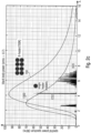
- Fig. 2b shows a matrix indicating the in-band power for different emitter configurations as a function of the temperature (and the resulting peak temperature). From the matrix of Fig. 2b can be derived that a number of four (4) heaters at 800K and a number of eight (8) heaters at 700K can roughly equal the emission intensity of a single heater at 1200K. Four (4) heaters at 1000K would approximately double the emission intensity of a single heater at 1200K.
- Fig. 2c shows a (simulated) emission spectrum for a single black body emitter at 1000 K and for an emitter arrangement having eight (8) black body emitters at a temperature of 700 K.
- the eight (8) black body emitters may comprise the same emission surface area each.
- the combined radiation intensity of 8 (7 or 8) thermal heaters (each) at 700K approximately corresponds to the radiation intensity of a single thermal heater at 1200K.
- the advantage is that the radiation of the cooler emitters, from a spectral point of view, is already clearly better in the intended spectral range around 4.26 ⁇ m (due to the less out-of-band radiation). Additionally, the effective waveguide area is enlarged, which results in an increased interaction area 25 for light-gas interaction, which finally makes the sensor more sensible due to an increased signal-to-noise ratio (SNR).
- SNR signal-to-noise ratio
- Table 1 Target Gas Target - Wavelength Peak - Temperature CO2 4.2 um 689.95 K CO 4.6 um 629.95 K CH4 2.3 um 986.75 K H2S 2.5 um 885.96 K H2S 7.0 um 413.97 K C2H3 6.9 um 591.38 K
- the waveguide structure 20 comprises a plurality of waveguides 20-1, .. , 20-# , wherein a respective one of the plurality of thermal radiation emitters 10-1, ..., 10-# is optically coupled to one of the plurality of waveguides 20-1, .., 20-#, and wherein the outputs 22-1, ..., 22-# of the plurality of waveguides 20-1, ..., 20-# are coupled to the thermal radiation detector 40.
- the plurality of waveguides 20-1, .. , 20-# may be arranged in a star-shaped, radial or radiant configuration, wherein the outputs 22-1, .. , 22-# of the plurality of waveguides 20-1, .. , 20-# are directed to a center region of the fluid sensor 100.
- the usage of several thermal emitters 10-1, ..., 10-# allows to implement a round and simultaneously star-shaped structure of the waveguides 20-1, ..., 20-# of the sensor arrangement 100 having a central detector 40.
- the detector 40 may have the shape of a polygon, such as a benzene ring or an octagon.
- the waveguides 20-1, ..., 20-# can run directly to a polygonal edge at a straight (orthogonal) angle.
- a unitary waveguide height of 650 - 750nm thickness polysilicon with different wavelengths a total reflection of the radiation R in the waveguides may be maintained. Therefore, it is possible to measure different target gases F T e.g., CO2 and O3 with the same system, for example.
- the thermal radiation detector 40 may arranged at a center region of the fluid sensor 100. According to an embodiment, the thermal radiation detector 40 may be formed as a polygon, so that a respective one of the plurality of waveguides 20-1, .. , 20-# reaches one of the polygon edges of the detector 40 in an orthogonal angle.
- the thermal radiation detector 40 may comprise a pyroelectric temperature sensor, a piezoelectric temperature sensor, a pn junction temperature sensor or a resistive temperature sensor.
- the optical filter structure 30 may comprise a plurality of optical filter elements 30-1, .. , 30-#, wherein each of the plurality of waveguides 20-1, .. , 20-# comprises (at least) one of the optical filter elements 30-1, .. , 30-# to filter the broadband thermal radiation R and to provide the filtered thermal radiation R F having the center wavelength ⁇ 0 .
- the filter elements 30-1, ..., 30-# of optical filter structure 30 may be formed as optical resonator elements having a narrow transmission band with a center wavelength ⁇ 0 , and wherein the optical filter structure 30 comprises a photonic crystal structure or a Bragg filter structure as wavelength selective optical elements for providing the filtered thermal radiation R F having the center wavelength ⁇ 0 .
- the optical filter elements 30-1, .. , 30-# of the optical filter structure 30 may be (essentially) formed at any position or intermediate position between the thermal emitters 10-1, ... , 10-# and the thermal detector.
- the optical filter elements 30-1, .. , 30-# of the optical filter structure 30 are formed between the waveguides 20-1, .. , 20-# and the thermal detector 40 (e.g. close to the to the detector 40).
- the optical filter elements 30-1, .. , 30-# of the optical filter structure 30 may be also formed between the thermal emitters 10-1, .. , 10-# and the waveguides 20-1, .. , 20-# (e.g. close to the thermal radiation emitters 10-#).
- the optical filter structure 30 is formed between the waveguides 20-1, .. , 20-# and the thermal detector 40 (e.g. close to the to the detector 40).
- the optical filter elements 30-1, .. , 30-# of the optical filter structure 30 may be also formed between the thermal emitters 10-1, .. , 10-# and the waveguides 20-1, .. , 20-# (e.g. close to the thermal radiation emitters 10-#).
- the optical filter elements 30-1, 30-2, ..., 30-# may be optionally placed close to the thermal radiation emitters 10-#..
- the thermal radiation emitters 10-1, ..., 10-# may comprise a semiconductor strip having a main emission surface region emitting a broadband thermal radiation in a main radiation emission direction and parallel or vertical to the waveguide structure.
- the coupling direction between the waveguide structure 20 and the thermal detector 40 may be parallel (in-plane) or vertical to the propagation direction of to the waveguide structure.
- the plurality of waveguides 20-1, .. , 20-# of the waveguide structure 20 may comprise strip waveguides, slot waveguides or rip waveguides.
- the fluid sensor 100 may be arranged on a substrate 70 which may form a common system plane for the sensor.
- the different elements of the fluid sensor 100 may be arranged on the substrate.
- the thermal radiation emitters 10 may comprise a semiconductor strip for emitting a broadband thermal radiation R, e.g., a broadband IR radiation. At least a part of the emitted thermal radiation R is coupled into the respective waveguide 20-1, ..., 20-# of the waveguide structure 20, wherein the emitted thermal radiation is infrared (IR) radiation or comprises infrared (IR) radiation.
- the substrate 70 may comprises a cavities 72-1, ..., 72-# vertically below the thermal radiation emitters 10-1, ..., 10-# 120 and (optionally) below the optical filter elements 30-1, ..., 30-# structure.
- the substrate 70 may also comprise a further cavity 74 vertically below the thermal radiation detector 40. The formation of the cavities in the substrate 70 below the thermal radiation emitters and optionally below the thermal radiation detector reduces the heat transfer from the thermal radiation emitter and/or the thermal radiation detector into the adjacent material so that the emission efficiency of the thermal radiation emitters as well as the detection efficiency of the thermal radiation detector can be increased.
- the filter elements (wavelength selective structures) 30-1, ..., 30-# may be formed as an IR filter, e.g. as a Fabry-Perot filter element (Bragg filter structure), or as a plasmonic structure (photonic crystal structure), e.g. as a plasmonic resonator for the emitted IR radiation.
- a Fabry-Perot filter element Bragg filter structure
- a plasmonic structure photonic crystal structure
- the thermal radiation detector 40 may comprise a pyroelectric temperature sensor, a piezoelectric temperature sensor, a pn junction temperature sensor or a resistive temperature sensor.
- the output signal S OUT may be converted by a high impedance amplifier, for example, into an amplified electrical output signal.
- Fig. 3 shows a schematic top view of a possible implementation of a fluid sensor 100 according to a further embodiment.
- the above evaluations of Figs. 1 and 2a-c of the elements of the fluid sensor device 100 and of the functionality thereof are equally applicable to the corresponding elements of the fluid sensor 100 of Fig. 3 .
- the fluid sensor 100 further comprises a waveguide structure 20 having a plurality of waveguides 20-1, 10-2, ..., 10-#, an optical filter structure 30 with a plurality of filter elements 30-1, 30-2, ..., 30-#, and a radiation detector 40 which is configured to provide a detector output signal S OUT based on a radiation strength of the filtered thermal radiation R F which is received by the thermal radiation detector 40 from the waveguide structure 20.
- the fluid sensor 100 further comprises an actuation device 50 for connecting the plurality of thermal radiation emitters 10 with a power source 60 for providing the thermal radiation emitters 10 in an actuated condition with electric energy so that the plurality of thermal radiation emitters 10 has an operating temperature between 400 and 1300 K.
- the thermal radiation detector 40 may be arranged at a center region of the fluid sensor 100.
- the thermal radiation detector 40 may be formed as a polygon, so that a respective one of the plurality of waveguides 20-1, .. , 20-# reaches one of the polygon edges of the detector 40 in an orthogonal angle.
- the plurality (e.g. 3, 4, 5, 7 or 8 or more) of waveguides 20-1, .. , 20-# may be arranged within a semi-circle or within in a segment of a circle in a star-shaped, radial or radiant configuration, wherein the outputs 22-1, .. , 22-# of the plurality of waveguides 20-1, .. , 20-# are directed to the central detector 40.
- the semi-circle arrangement (of the waveguides) of the fluid sensor 100 has, for example, five (5) emitters 10- 1, ..., 10-5, five waveguides 20-1, ..., 20-5, and five filter elements 30-1, ..., 30-5.
- the radial design of the structure (of the fluid sensor 100) comprises on the outside are the heaters 10- 1, ..., 10-# emitting the black body radiation R and couple into the waveguide 20-1, ..., 20-#.
- the filter elements (e.g. photonic crystal filters) 30-1, ..., 30-# are at the end (or at the beginning or at an intermediate position therebetween) of the waveguides 20-1, ..., 20-#. If different filter elements (e.g. photonic crystal filters) 30-1, ..., 30-# are used after the heaters 10-1, ..., 10-#, multi gas measurements are possible, for example carbon dioxide CO 2 and ozone O 3 as the different target gases (fluids) F T .
- Fig. 4 shows a schematic top view of a further implementation of a fluid sensor 100 according to a further embodiment.
- the above evaluations of Figs. 1 , 2a-c and 3 of the elements of the fluid sensor device 100 and of the functionality thereof are equally applicable to the corresponding elements of the fluid sensor 100 of Fig. 3 .
- the fluid sensor 100 further comprises a waveguide structure 20 having a plurality of waveguides 20-1, 10-2, ..., 10-#, an optical filter structure 30 with a plurality of filter elements 30-1, 30-2, ..., 30-#, and a radiation detector 40 which is configured to provide a detector output signal S OUT based on a radiation strength of the filtered thermal radiation R F which is received by the thermal radiation detector 40 from the waveguide structure 20.
- the fluid sensor 100 further comprises an actuation device 50 for connecting the plurality of thermal radiation emitters 10 with a power source 60 for providing the thermal radiation emitters 10 in an actuated condition with electric energy so that the plurality of thermal radiation emitters 10 has an operating temperature between 400 and 1300 K.
- the thermal radiation detector 40 may be arranged at a center region of the fluid sensor 100.
- the thermal radiation detector 40 may be formed as a polygon, so that a respective one of the plurality of waveguides 20-1, .. , 20-# reaches one of the polygon edges of the detector 40 in an orthogonal angle.
- the plurality (e.g. 3, 4, 5, 7 or 8) of waveguides 20-1, .. , 20-# may be arranged within a full circle in a star-shaped, radial or radiant configuration, wherein the outputs 22-1, .. , 22-# of the plurality of waveguides 20-1, .. , 20-# are directed to the central detector 40.
- the full-circle arrangement (of the waveguides) of the fluid sensor 100 has, for example, eight (8) emitters 10- 1, ..., 10-8, eight waveguides 20-1, ... , 20-8, and eight filter elements 30-1, ..., 30-8.
- the radial design of the structure (of the fluid sensor 100) comprises on the outside are the heaters 10- 1, ..., 10-# emitting the black body radiation R and couple into the waveguide 20-1, ..., 20-#.
- the filter elements (e.g. photonic crystal filters) 30-1, ..., 30-# are at the end (or at the beginning or at an intermediate position therebetween) of the waveguides 20-1, ..., 20-#. If different filter elements (e.g. photonic crystal filters) 30-1, ..., 30-# are used after the heaters 10-1, ..., 10-#, multi gas measurements are possible, for example carbon dioxide CO 2 and ozone O 3 as the different target gases (fluids) F T .
- Figs. 5a-c show schematic cross-sectional views of different possible implementations of the arrangement of one of the plurality of "sections" of the fluid sensor 100 according to an embodiment.
- the thermal radiation emitters 10-1, ..., 10-# may comprise a semiconductor strip (wire) having a main emission surface region emitting the broadband thermal radiation R in a main radiation emission direction and parallel or vertical to the waveguide structure.
- the coupling direction between the waveguide structure 20 and the thermal detector 40 may be parallel (in-plane) or vertical to the propagation direction of to the waveguide structure.
- the coupling area 10-20 is respectively between the thermal emitter 10-# and the waveguide structure 20-#, and the coupling area 20-30 is respectively between the waveguide structure 20-# and the thermal detector 40.
- the coupling direction between the thermal emitter 10-# and the waveguide structure 20-# and the coupling direction between the waveguide structure 20-# and the thermal detector 40 may be parallel (in-plane) to the propagation direction of to the waveguide structure 20.
- the thermal emitter 10-#, the waveguide structure 20-# and the thermal detector 40 may be arranged in the same plane.
- the coupling direction between the thermal emitter 10-# and the waveguide structure 20-# and the coupling direction between the waveguide structure 20-# and the thermal detector 40 may be vertical (up and/or down) to the propagation direction of to the waveguide structure 20.
- the thermal emitter 10-# and the thermal detector 40 may be arranged in the same (first) plane, wherein the waveguide structure 20-# may be arranged in a further (second) plane.
- the thermal emitter 10-#, the waveguide structure 20-# and the thermal detector 40 may be arranged in the three different planes.
- the fluid senor 100 may also be implemented as a multi-fluid sensor, if different filter elements (e.g. photonic crystal filters) 30-1, ..., 30-# are used after the heaters 10-1, ..., 10-#.
- filter elements e.g. photonic crystal filters
- multi gas measurements are possible, for example for measuring the ratio of carbon dioxide CO 2 and ozone O 3 as the different target gases (fluids) F T in the surrounding atmosphere.
- the fluid sensor 100 as described with respect to figures 1- 5 may be implemented as a multi-fluid sensor.
- the above evaluations of Figs. 1 to 5 of the elements of the fluid sensor device 100 and of the functionality thereof are equally applicable to the corresponding elements of the multi-fluid sensor 100.
- a multi-fluid sensor comprises the fluid sensor 100 as described above, wherein the waveguide structure 10 comprises a plurality of waveguides 20-1, ..., 20-#, wherein a respective one of the plurality of thermal radiation emitters 10-1, ..., 10-# is optically coupled to a respective one of the plurality of waveguides 20-1, ..., 20-#, and wherein the optical filter structure 30 comprises a plurality of optical filter elements 30-1, ..., 30-#.
- a first group of the optical filter elements 30-1, ..., 30-#, which is optically coupled to a first group of the plurality of waveguides 20-1, ..., 20-#, is configured to filter the broadband thermal radiation R of the first group of thermal radiation emitters 10-1, ..., 10-# to provide a filtered thermal radiation R F , having a first center wavelength ⁇ 1
- a second group of the optical filter elements 30-1, ..., 30-#, which is optically coupled to a second group of the plurality of waveguides 20-1, ..., 20-#, is configured to filter the broadband thermal radiation R of the second group of thermal radiation emitters 10-1, ..., 10-# to provide a filtered thermal radiation R F2 having a second center wavelength ⁇ 2 .
- the first center wavelength ⁇ 1 corresponds to an absorption band of a first target fluid F T1
- the second center wavelength ⁇ 2 corresponds to an absorption band of a second target fluid F T2 .
- the operating temperature T 1 of the first group of the plurality of thermal radiation emitters 10-1, ..., 10-#, which is optically coupled to the first group of the plurality of waveguides 20-1, ..., 20-#, is adjusted so that an absorption band or spectral line of a first target fluid F T1 is within a (tolerance) range of ⁇ 10% or ⁇ 2% at a peak intensity value of the IR emission spectrum of the first group of the plurality of thermal radiation emitters 10-1, ..., 10-#.
- the operating temperature T 2 of a second group of the plurality of thermal radiation emitters 10-1, ..., 10-#, which is optically coupled to the second group of the plurality of waveguides 20-1, ..., 20-#, is adjusted so that an absorption band or spectral line of a second target fluid T F2 is within a (tolerance) range of ⁇ 10% or ⁇ 2% at a peak intensity value of the IR emission spectrum of the second group of the plurality of thermal radiation emitters 10-1, ..., 10-#.
- a fluid sensor for detecting a target fluid comprises a plurality of thermal radiation emitters for emitting a broadband thermal radiation, a waveguide structure configured to guide the emitted thermal radiation emitted from the plurality of thermal radiation emitters, wherein the guided thermal radiation comprises an evanescent field component for interacting with the surrounding atmosphere comprising the target fluid, an optical filter structure coupled to the waveguide structure, wherein the optical filter structure is configured to filter the broadband thermal radiation emitted by the thermal radiation emitter and to provide a filtered thermal radiation having a center wavelength ( ⁇ 0 ), a thermal radiation detector configured to provide a detector output signal based on a radiation strength of the filtered thermal radiation received from the waveguide structure, and an actuation device for connecting the plurality of thermal radiation emitters with a power source for providing the thermal radiation emitters in an actuated condition with electric energy so that the plurality of thermal radiation emitters has an operating temperature between 400 to 1300 K .
- the operating temperature of the plurality of thermal radiation emitters is adjusted so that an absorption band or spectral line of the target fluid is within a range of ⁇ 10% at a peak intensity value of the IR emission spectrum of the plurality of thermal radiation emitters.
- the operating temperature of the plurality of thermal radiation emitters is adjusted to be between 550K and 800K or between 620K and 720K so that an absorption band or spectral line of carbon dioxide (CO 2 ) as the target fluid or of ozone (O 3 ) as the target fluid is within a tolerance range of ⁇ 10% at a peak intensity value of the IR emission spectrum of the plurality of thermal radiation emitters.
- the waveguide structure comprises a plurality of waveguides, wherein a respective one of the plurality of thermal radiation emitters is optically coupled to one of the plurality of waveguides, and wherein the outputs of the plurality of waveguides are coupled to the thermal radiation detector.
- the plurality of waveguides are arranged in a star-shaped, radial or radiant configuration, and wherein the outputs of the plurality of waveguide are directed to a center region of the fluid sensor.
- the thermal radiation detector is arranged at a center region of the fluid sensor.
- the thermal radiation detector is formed as a polygon, so that a respective one of the plurality of waveguides reaches one of the polygon edges of the detector in an orthogonal angle.
- the waveguide structure comprises a joint waveguide, wherein the broadband thermal radiation of the plurality of thermal radiation emitters is coupled into the joint waveguide, and wherein the output of the joint waveguide is coupled to the thermal radiation detector.
- the optical filter structure comprises a plurality of optical filter elements, wherein each of the plurality of waveguides comprises at least one of the optical filter elements to filter the broadband thermal radiation and to provide the filtered thermal radiation having the center wavelength ( ⁇ 0 ).
- the optical filter structure is formed as an optical resonator structure having a narrow transmission band with a center wavelength ⁇ 0 , and wherein the optical filter structure comprises a photonic crystal structure or a Bragg filter structure as wavelength selective optical elements for providing the filtered thermal radiation having the center wavelength.
- the thermal radiation emitters comprise a semiconductor strip having a main emission surface region emitting a broadband thermal radiation in a main radiation emission direction and parallel to the waveguide structure.
- the waveguide structure comprises a strip waveguide, a slap waveguide, a slot waveguide or a rip waveguide.
- the thermal radiation detector comprises a pyroelectric temperature sensor, a piezoelectric temperature sensor, a pn-junction temperature sensor or a resistive temperature sensor.
- a multi-fluid sensor comprises the above fluid sensor, wherein the waveguide structure comprises a plurality of waveguides, wherein a respective one of the plurality of thermal radiation emitters is optically coupled to a respective one of the plurality of waveguides, and wherein the optical filter structure comprises a plurality of optical filter elements, wherein a first group of the optical filter elements, which is optically coupled to a first group of the plurality of waveguides, is configured to filter the broadband thermal radiation of the first group of thermal radiation emitters to provide a filtered thermal radiation having a first center wavelength ( ⁇ 1 ), and wherein a second group of the optical filter elements, which is optically coupled to a second group of the plurality of waveguides, is configured to filter the broadband thermal radiation of the second group of thermal radiation emitters to provide a filtered thermal radiation having a second center wavelength ( ⁇ 2 ).
- the first center wavelength ( ⁇ 1 ) corresponds to an absorption band of a first target fluid
- the second center wavelength ( ⁇ 2 ) corresponds to an absorption band of a second target fluid
- the operating temperature of the first group of the plurality of thermal radiation emitters is adjusted so that an absorption band or spectral line of a first target fluid is within a range of ⁇ 10% at a peak intensity value of the IR emission spectrum of the first group of the plurality of thermal radiation emitters
- the operating temperature of a second group of the plurality of thermal radiation emitters is adjusted so that an absorption band or spectral line of a second target fluid is within a range of ⁇ 10% at a peak intensity value of the IR emission spectrum of the second group of the plurality of thermal radiation emitters.
Landscapes
- Physics & Mathematics (AREA)
- Chemical & Material Sciences (AREA)
- Health & Medical Sciences (AREA)
- Life Sciences & Earth Sciences (AREA)
- Spectroscopy & Molecular Physics (AREA)
- General Physics & Mathematics (AREA)
- Biochemistry (AREA)
- General Health & Medical Sciences (AREA)
- Analytical Chemistry (AREA)
- Immunology (AREA)
- Pathology (AREA)
- Engineering & Computer Science (AREA)
- Combustion & Propulsion (AREA)
- Food Science & Technology (AREA)
- Medicinal Chemistry (AREA)
- Investigating Or Analysing Materials By Optical Means (AREA)
Abstract
Description
- Embodiments relate in general to the field of sensor devices and, more specifically, to the field of fluid sensors for detecting a target fluid (fluid = gas or liquid). In particular, embodiments relate to a multi emitter/waveguide MIRS system (MIRS = mid-infrared sensor) having, for example, a single radiation detector, e.g. a single piezo detector.
- The detection of environmental parameters, e.g. gas components, in the ambient atmosphere is becoming increasingly important in the implementation of appropriate sensors within mobile devices, for example, but also in the application in home automation, such as smart home, and, for example, in the automotive sector. The field of monitoring the air quality and the gas composition in our environment becomes more and more attention. However, with the evermore extensive use of sensors, there is also a particular need to be able to produce such sensors cost-effectively, wherein the resulting reliability and accuracy of the sensors should be as high as possible.
- A typical optical gas sensor comprises a light source, filter elements for a wavelength selection, a sample area and a detector. The guided light between the light source and the detector interacts in the sample area with the environmental medium. Typically, large efforts are necessary to provide effective filter elements for a sufficient wavelength selection for achieving an adequate sensitivity.
- Generally, there is a need in the art for an approach to implement improved fluid sensors having low fabrication requirements and providing an adequate sensitivity for the target fluid to be detected by the sensor device.
- Such a need can be solved by the fluid sensor according to
claim 1 and by the multi-fluid sensor according toclaim 14. - Specific developments and implementations of the fluid sensor and the multi-fluid sensor are defined in the dependent claims.
- According to an embodiment, a fluid sensor for detecting a target fluid comprises a plurality of thermal radiation emitters for emitting a broadband thermal radiation, a waveguide structure configured to guide the emitted thermal radiation emitted from the plurality of thermal radiation emitters, wherein the guided thermal radiation comprises an evanescent field component for interacting with the surrounding atmosphere comprising the target fluid, an optical filter structure coupled to the waveguide structure, wherein the optical filter structure is configured to filter the broadband thermal radiation emitted by the thermal radiation emitter and to provide a filtered thermal radiation having a center wavelength (λ0), a thermal radiation detector configured to provide a detector output signal based on a radiation strength of the filtered thermal radiation received from the waveguide structure, and an actuation device for connecting the plurality of thermal radiation emitters with a power source for providing the thermal radiation emitters in an actuated condition with electric energy so that the plurality of thermal radiation emitters has an operating temperature between 400 to 1300 K.
- According to an embodiment, the operating temperature of the plurality of thermal radiation emitters may be adjusted so that an absorption band or spectral line of the target fluid is within a (tolerance) range of ± 10% at a peak intensity value of the IR emission spectrum of the plurality of thermal radiation emitters.
- According to an embodiment, the waveguide structure may comprise a plurality of waveguides, wherein a respective one of the plurality of thermal radiation emitters is optically coupled to one of the plurality of waveguides, and wherein the outputs of the plurality of waveguides are coupled to the thermal radiation detector.
- According to an embodiment, a multi-fluid sensor comprises the above fluid sensor, wherein the waveguide structure comprises a plurality of waveguides, wherein a respective one of the plurality of thermal radiation emitters is optically coupled to a respective one of the plurality of waveguides, and wherein the optical filter structure comprises a plurality of optical filter elements. A first group of the optical filter elements, which is optically coupled to a first group of the plurality of waveguides, is configured to filter the broadband thermal radiation of the first group of thermal radiation emitters to provide a filtered thermal radiation having a first center wavelength (λ1), and a second group of the optical filter elements, which is optically coupled to a second group of the plurality of waveguides, is configured to filter the broadband thermal radiation of the second group of thermal radiation emitters to provide a filtered thermal radiation having a second center wavelength (λ2).
- According to an embodiment, the first center wavelength (λ1) may correspond to an absorption band of a first target fluid, and wherein the second center wavelength (λ2) may correspond to an absorption band of a second target fluid.
- Embodiments of the present fluid sensor and of the multi-fluid sensor are described herein in detail with respect to the appended drawings and figures, in which:
- Fig. 1a-c
- show a schematic top view (plan view) of a fluid sensor according to an embodiment;
- Fig. 2a
- shows a (simulated) emission spectrum for a black body emitter at different temperatures according to the Planck's Law and the Wien's Displacement Law;
- Fig. 2b
- shows a matrix indicating the in-band power for different emitter configurations as a function of the temperature (and the resulting peak temperature);
- Fig. 2c
- shows a (simulated) emission spectrum for a single black body emitter at 1000 K and for an emitter arrangement having eight (8) black body emitters at a temperature of 700 K;
- Fig. 3
- shows a schematic top view of a possible implementation of a fluid sensor according to a further embodiment;
- Fig. 4
- shows a schematic top view of a further implementation of a fluid sensor according to a further embodiment;
- Figs. 5a-c
- show schematic cross-sectional views of different possible implementations of one of the plurality of "sections or branches" of the fluid sensor according to an embodiment.
- In the following description, embodiments are discussed in further detail using the figures, wherein in the figures and the specification identical elements and elements having the same functionality and/or the same technical or physical effect are provided with the same reference numbers or are identified with the same name. Thus, the description of these elements and of the functionality thereof as illustrated in the different embodiments are mutually exchangeable or may be applied to one another in the different embodiments.
- In the following description, embodiments are discussed in detail, however, it should be appreciated that the embodiments provide many applicable concepts that can be embodied in a wide variety of semiconductor devices. The specific embodiments discussed are merely illustrative of specific ways to make and use the present concept, and do not limit the scope of the embodiments. In the following description of embodiments, the same or similar elements having the same function have associated therewith the same reference signs or the same name, and a description of such elements will not be repeated for every embodiment. Moreover, features of the different embodiments described hereinafter may be combined with each other, unless specifically noted otherwise.
- In the description of the embodiments, terms and text passages placed in brackets (next to a described element or function) are to be understood as further explanations, exemplary configurations, exemplary additions and/or exemplary alternatives of the described element or function.
- It is understood that when an element is referred to as being "connected" or "coupled" to another element, it may be directly connected or coupled to the other element, or intermediate elements that may be present. Conversely, when an element is referred to as being "directly" connected to another element, "connected" or "coupled," there are no intermediate elements. Other terms used to describe the relationship between elements should be construed in a similar fashion (e.g., "between" versus "directly between", "adjacent" versus "directly adjacent", and "on" versus "directly on", etc.).
- For facilitating the description of the different embodiments, some of the figures comprise a Cartesian coordinate system x, y, z, wherein the x-y-plane corresponds, i.e. is parallel, to a main surface region (= a reference plane = x-y-plane) of a substrate, for example, wherein the direction vertically up with respect to the reference plane (x-y-plane) corresponds to the "+z" direction, and wherein the direction vertically down with respect to the reference plane (x-y-plane) corresponds to the "-z" direction. In the following description, the term "lateral" means a direction parallel to the x- and/or y-direction or a direction parallel to (or in) the x-y-plane, wherein the term "vertical" means a direction parallel to the z-direction.
-
Fig. 1a-c show a schematic top view of afluid sensor 100 for detecting a target fluid FT according to an embodiment. - The
fluid sensor 100 is arranged for sensing an amount or a concentration of a target fluid or a target fluid component FT in the surrounding atmosphere, e.g. an environmental medium. In the present context, the term "fluid" may relate to a liquid or a gas. In case the environmental medium relates to environmental air, the target fluid may relate to a target gas or a target gas component which is present in the environmental air. The present concept is equally applicable to sensing a target liquid or a target liquid component in the environmental medium (fluid). - As shown in
Fig. 1a-c , thefluid sensor 100 comprises a plurality of (at least two) thermal radiation emitters 10-1, 10-2, ..., 10-# (# is a placeholder for an integer greater-than-or-equal to two; # ≥ 2) for emitting a broadband thermal radiation R. Thefluid sensor 100 further comprises a waveguide structure 20 (= 20-1, 20-2, ..., 20-# inFig. 1 a or 20', 20-1, 20-2, ..., 20-# inFig. 1c ) configured to guide the emitted thermal radiation R which is emitted from the plurality of thermal radiation emitters 10-1, 10-2, ..., 10-# wherein the guided thermal radiation R comprises an evanescent field component for interacting with the surrounding atmosphere (medium) comprising the target fluid FT. - The
fluid sensor 100 further comprises an optical filter structure 30 (= 30-1, 30-2, ..., 30-#) which is coupled to thewaveguide structure 20. Theoptical filter structure 30 is configured to filter the broadband thermal radiation R which is emitted by thethermal radiation emitters 10, and to provide a filtered thermal radiation RF having a center wavelength λ0. - As exemplarily shown in
Fig. 1b , the optical filter structure 30 (= 30-1, 30-2, ..., 30-#) may be placed close to the detector 40 (example A ofFig. 1b ) or the optical filter structure 30 (= 30-1, 30-2, ..., 30-#) may be placed close to the thermal radiation emitters 10-# (example B ofFig. 1b ). In case, theoptical filter structure 30 with the filter elements 30-1, 30-2, ..., 30-# is placed close to the thermal radiation emitter 10-#, the emitted light (thermal radiation R) would be directly (after emission) filtered already, wherein only the remaining 1% inband light would be transmitted towards thedetector 40. So the light (thermal radiation R) becomes selective immediately. The arrangement of example B may save about a light energy of 99% unwanted and unfiltered light compared to the arrangement of example A. - The
fluid sensor 100 further comprises aradiation detector 40 which is configured to provide a detector output signal SOUT based on a radiation strength of the filtered thermal radiation RF which is received by thethermal radiation detector 40 from thewaveguide structure 20. Thefluid sensor 100 further comprises anactuation device 50 for connecting the plurality ofthermal radiation emitters 10 with apower source 60 for providing thethermal radiation emitters 10 in an actuated condition with electric energy so that the plurality ofthermal radiation emitters 10 has an operating temperature between 400 and 1300 K. - As shown in
Fig. 1a , thewaveguide structure 20 may comprise a plurality of waveguides 20-1, 10-2, ..., 10-#, wherein a respective one of the plurality of thermal radiation emitters 10-1, 10-2, ..., 10-# is optically coupled to one of the plurality of waveguides 20-1, 20-2, ..., 20-#, and wherein the outputs 22-1, 22-2, ..., 22-# of the plurality of waveguides 20-1, 20-2, ..., 20-# are coupled to thethermal radiation detector 40. - According to embodiments, the waveguides 20-1, 20-2, ..., 20-# of the
waveguide structure 20 extend or pass through the interaction area (region) 25 (= 25-1, .., 25-#), where the waveguides 20-1, 20-2, ..., 20-# of thewaveguide structure 20 are surrounded by or in contact with the surrounding atmosphere. Thus, the waveguides 20-1, 20-2, ..., 20-# of thewaveguide structure 20 guide the thermal radiation R having the evanescent field component through theinteraction area 25, where the evanescent field components of the guided radiation interact with the surrounding atmosphere comprising the target fluid FT. - Each of the waveguides (or waveguide branches) 20-1, 20-2, ..., 20-# of the
waveguide structure 20 may comprise the optical filter structure 30-1, 30-2, ..., 30-# to filter the broadband thermal radiation R emitted by each of the thermal radiation emitters 10-1, 10-2, ..., 10-# and to provide a filtered thermal radiation RF having the center wavelength λ0. - As exemplarily shown in
Fig. 1c , thewaveguide structure 20 may comprise according to a further embodiment a joint waveguide (common waveguide) 20', wherein the broadband thermal radiation R of the plurality of thermal radiation emitters 10-1, 10-2, ..., 10-# is coupled into the joint waveguide 20', and wherein theoutput 22 of the joint waveguide 20' is coupled to the thermal radiation anddetector 40. Thus, a plurality of branches (separate segments or sections) 20-1, 20-2, ..., 20-# of thewaveguide structure 20 may be merged to form the joint waveguide 20'. - According to an embodiment, the
waveguide structure 20 having the joint waveguide (common waveguide) may extend or pass through theinteraction area 25, where thewaveguide structure 20 is surrounded by or in contact with the surrounding atmosphere. Thus, (1.) only the branches 20-1, 20-2, ..., 20-# of thewaveguide structure 20, or (2.) the branches 20-1, 20-2, ..., 20-# of thewaveguide structure 20 and the joint waveguide 20', or (3.) only by the joint waveguide 20' may extend or pass through the interaction area (region) 25, where the evanescent field component of thewaveguide structure 20 interacts with the surrounding atmosphere comprising the target fluid FT. Moreover, theoptical filter structure 30 may be arranged in each of the branches 20-1, 20-2, ..., 20-# of thewaveguide structure 20 or in thejoint waveguide structure 20. - Having a plurality of (optically parallel) waveguides (waveguide branches) 20-1, 20-2, ..., 20-#, which extend or pass through the
interaction area 25, may provide a high (e.g. an increased) efficiency of sensing in the evanescent field as the effective interaction area (interaction length) with the surrounding atmosphere is high (e.g. increased, when compared to a joint waveguide structure). - According to the embodiment of
Figs. 1a-c , thewaveguide structure 20 may comprise, for example, a semiconductor material or a dielectric material, and is configured to guide the IR radiation R by total reflection. The guided IR radiation R comprises an evanescent field component, i.e., a field component outside thewaveguide structure 20, for interacting with the surrounding atmosphere comprising the target fluid FT, i.e., a target liquid or a target gas. The interaction of the evanescent field component with the surrounding atmosphere results in a reduction of the transmitted thermal radiation R (in the absorption band or spectral line of the target fluid FT) due to absorption of the guided radiation R (in the absorption band or spectral line of the target fluid FT). The (degree of) absorption is a measure for the target fluid concentration in the surrounding atmosphere or medium. - According to an embodiment, the operating temperature T of the plurality of thermal radiation emitters 10 (= 10-1, 10-2, ..., 10-#) is adjusted (e.g. by the actuation device 50), so that an absorption band or spectral line of the target fluid FT is within a range (tolerance range) of +/- 10%, +/- 5% or +/- 2 % at a peak intensity value of the IR emission spectrum of the plurality of thermal radiation emitters 10-1, 10-2, ..., 10-#.
- The range (tolerance range) of +/- 10%, +/- 5% or +/- 2 % may relate to the wavelength λBAND of the absorption band or spectral line of the target fluid FT with respect to the wavelength λPEAK of the peak intensity value of the emission spectrum, for example with 1.1 ≥ λBAND / λPEAK ≥ 0.9; 1.05 ≥λBAND / λPEAK ≥ 0.95; or 1.02 ≥ λAND / λPEAK ≥ 0.98. Alternatively, the range (tolerance range) of +/- 10%, +/- 5% or +/- 2 % may relate to the peak intensity value IMAX of the emission spectrum, wherein the wavelength λBAND of the absorption band or spectral line of the target fluid FT range is at a position where the emission spectrum has at least 90%, 95% or 98% of its peak intensity value IMAX of the thermal radiation R.
- With respect to the chosen peak intensity value of the IR emission spectrum of the plurality of thermal radiation emitters 10 (10-1, 10-2, ..., 10-#) it is now referred to
Figs. 2a-b . -
Fig. 2a shows a (simulated) emission spectrum (= spectral power density or radiation intensity) for a black body emitter 10-1, ..., 10-# at different temperatures T according to the Planck's Law and the Wien's Displacement Law. The Wien's displacement law states that the black-body radiation curve for different temperatures will peak at different wavelengths that are inversely proportional to the temperature T. The shift of that peak is a direct consequence of the Planck radiation law, which describes the spectral brightness or intensity of black-body radiation as a function of wavelength at any given temperature. - In the following exemplary embodiment, the detection of carbon dioxide (CO2) as the target fluid FT is described, wherein carbon dioxide (CO2) has its absorption band or spectral line approximately at 4,26 µm or in a range between 4,14 and 4,35pm.
- Using a temperature range of about 1200 K for operating the
thermal emitters 10 would provide a sufficient radiation intensity "I" of the emitted broadband thermal radiation R. However, according to the Plank's law or Wien's distribution law, at 1200K, the proportion of the CO2 wavelength (absorption band or spectral line) of 4.26µm is only a small proportion of the overall emitted radiation. All other wavelengths (and the wavelength range around the peak intensity value) outside a narrow spectral range around 4.26 µm can react with other gases than CO2.Thus, unwanted cross-sensitivities can occur. - Thus, according to the present embodiment, the
fluid sensor 100 comprises a plurality (e.g. at least 2 or 3, 4, 5, 6, 7, 8 or more) of thermal radiation emitters 10-1, ..., 10-#, wherein the operating temperature T of the plurality of thermal radiation emitters 10-1, 10-2, ..., 10-# is adjusted, so that an absorption band or spectral line of the target fluid FT is within a range of +/- 10% or less (e.g. +/- 5% or +/- 2 %) at a peak intensity value of the IR emission spectrum of the plurality ofthermal radiation emitters 10. - Thus, using a plurality of
thermal radiation emitters 10 having an operating temperature T, so that the peak intensity value of the IR emission spectrum essentially corresponds to the absorption band or spectral line of the target fluid FT, provides a sufficient radiation intensity "I" of the emitted broadband thermal radiation R. According to the Plank's law or Wien's distribution law, at 700K, the proportion of the CO2 wavelength 4.26µm is a large proportion of the overall emitted radiation. All other wavelengths outside a narrow spectral range around 4.26 µm can react with other gases than CO2 only in a reduced way. Thus, unwanted cross-sensitivities can be avoided or at least effectively reduced. - According to embodiments, the
fluid sensor 100 may be implemented as a mid-wave infrared radiation sensors (MIRS). TheMIRS 100 essentially comprises the plurality of thermal radiation emitters (sources) 10, which emit, in the black body spectrum, the broadband IR radiation R. The radiation R is coupled into the waveguides 20-1, ..., 20-#. For achieving the filtered (as monochromatic as possible) IR radiation RF, the respective filter structures 30-1, ..., 30-#, e.g. photonic crystal filters, are respectively coupled to or implemented in the waveguides 20-1, ... , 20-# for transmitting the required wavelength. In case, carbon dioxide CO2 is the target gas, the filter structures may be optimized for the wavelength (= the absorption band or spectral line) of 4.26µm (+/- 2 %). The IR radiation R is coupled in the waveguide and a surrounding evanescent field is formed, wherein the wavelength of the radiation R in the absorption band or spectral line of the target gas FT is absorbed, e.g. by the CO2 in the ambient atmosphere. The reduction of the intensity of the radiation R in the wavelength (range) of the absorption band or spectral line of the target gas is a measure for the concentration of target gas FT, such as CO2. - Due to the utilization of the plurality of thermal emitters 10-1, ..., 10-#, a relatively low temperature (e.g. 650K or 700 K) is needed at the thermal emitters 10-1, ..., 10-# in order to pass through the
waveguide structure 20 with a sufficient amount of heat. Moreover, according to the Plank's law or Wien's distribution law, at 650K or 700K, the proportion of the CO2 wavelength 4.26µm is a large proportion of the overall emitted radiation R. - Thus, the
fluid sensor 100 can ensure a clean (effective) measurement. Thus, a sufficient radiation energy (guided in the waveguides 20) impinges onto thethermal radiation detector 40, e.g. a piezo detector or a pn diode detector, as the attenuation for the wavelength λ0 (of the absorption band or spectral line of the target gas) on the path through thewaveguides 20 is sufficiently low. - According to the present concept, a plurality of thermal heaters 10-1, ..., 10-# are used as a thermal source in order to bring the necessary amount of heat to the
detector 40. -
Fig. 2b shows a matrix indicating the in-band power for different emitter configurations as a function of the temperature (and the resulting peak temperature). From the matrix ofFig. 2b can be derived that a number of four (4) heaters at 800K and a number of eight (8) heaters at 700K can roughly equal the emission intensity of a single heater at 1200K. Four (4) heaters at 1000K would approximately double the emission intensity of a single heater at 1200K. -
Fig. 2c shows a (simulated) emission spectrum for a single black body emitter at 1000 K and for an emitter arrangement having eight (8) black body emitters at a temperature of 700 K. The eight (8) black body emitters may comprise the same emission surface area each. According to embodiments, it is derivable from calculations and simulations that approximately 8 (7 or 8) sources (heaters) 10-# can be operated at 700K to get approximately the same amount of heat at thedetector 40 as a comparable emitter at 1200K. Thus, the combined radiation intensity of 8 (7 or 8) thermal heaters (each) at 700K approximately corresponds to the radiation intensity of a single thermal heater at 1200K. The advantage is that the radiation of the cooler emitters, from a spectral point of view, is already clearly better in the intended spectral range around 4.26µm (due to the less out-of-band radiation). Additionally, the effective waveguide area is enlarged, which results in an increasedinteraction area 25 for light-gas interaction, which finally makes the sensor more sensible due to an increased signal-to-noise ratio (SNR). - According to an embodiment, the operating temperature T of the plurality of thermal radiation emitters 10-1, 10-2, ..., 10-# may be adjusted to a temperature range between 550 and 800 K, 600 and 700 K or 620 and 680 K so that the absorption band or spectral line of the target gas, e.g. CO2, O3, ... (λCO2 = 4.2, ...)) is within the range of +/- 10%, 5 % or 2 % at the peak intensity value of the IR emission spectrum of the plurality of thermal radiation emitters 10-1, 10-2, ..., 10-#.
- The following table provides some further examples of target gases and the associated emitter temperatures (for matching the absorption band of the respective target gas).
Table 1: Target Gas Target - Wavelength Peak - Temperature CO2 4.2 um 689.95 K CO 4.6 um 629.95 K CH4 2.3 um 986.75 K H2S 2.5 um 885.96 K H2S 7.0 um 413.97 K C2H3 6.9 um 591.38 K - According to further embodiments, the operating temperature T of the plurality of thermal radiation emitters 10-1, 10-2, ..., 10-# may be adjusted to a temperature range between 400 and 1000 K, so that the absorption band or spectral line of the target gas, e.g. CO2, CO, CH4, H2S, C2H3, ... (λCO2 = 4.2, λCO = 4.6, λCH4 = 2.3, λH2S = 2.5 and 7.0, λC2H3 = 6.9 ...) is within the range of +/- 10%, 5 % or 2 % at the peak intensity value of the IR emission spectrum of the plurality of thermal radiation emitters 10-1, 10-2, ..., 10-#.
- The above evaluations and embodiments are equally applicable to other target fluids having a different absorption band or spectral line.
- According to a further embodiment, the
waveguide structure 20 comprises a plurality of waveguides 20-1, .. , 20-# , wherein a respective one of the plurality of thermal radiation emitters 10-1, ..., 10-# is optically coupled to one of the plurality of waveguides 20-1, .., 20-#, and wherein the outputs 22-1, ..., 22-# of the plurality of waveguides 20-1, ..., 20-# are coupled to thethermal radiation detector 40. The plurality of waveguides 20-1, .. , 20-# may be arranged in a star-shaped, radial or radiant configuration, wherein the outputs 22-1, .. , 22-# of the plurality of waveguides 20-1, .. , 20-# are directed to a center region of thefluid sensor 100. - According to an embodiment, the usage of several thermal emitters 10-1, ..., 10-# allows to implement a round and simultaneously star-shaped structure of the waveguides 20-1, ..., 20-# of the
sensor arrangement 100 having acentral detector 40. The diameter (= lateral extension) of the sensor arrangement (fluid sensor) 100 may be in a range between 2 and 10 µm or between 4 and 8 µm. - According to an embodiment, the
detector 40 may have the shape of a polygon, such as a benzene ring or an octagon. Thereby, the waveguides 20-1, ..., 20-# can run directly to a polygonal edge at a straight (orthogonal) angle. As a unitary waveguide height of 650 - 750nm thickness polysilicon with different wavelengths, a total reflection of the radiation R in the waveguides may be maintained. Therefore, it is possible to measure different target gases FT e.g., CO2 and O3 with the same system, for example. - According to a further embodiment, the
thermal radiation detector 40 may arranged at a center region of thefluid sensor 100. According to an embodiment, thethermal radiation detector 40 may be formed as a polygon, so that a respective one of the plurality of waveguides 20-1, .. , 20-# reaches one of the polygon edges of thedetector 40 in an orthogonal angle. - According to a further embodiment, the
thermal radiation detector 40 may comprise a pyroelectric temperature sensor, a piezoelectric temperature sensor, a pn junction temperature sensor or a resistive temperature sensor. - According to a further embodiment, the
optical filter structure 30 may comprise a plurality of optical filter elements 30-1, .. , 30-#, wherein each of the plurality of waveguides 20-1, .. , 20-# comprises (at least) one of the optical filter elements 30-1, .. , 30-# to filter the broadband thermal radiation R and to provide the filtered thermal radiation RF having the center wavelength λ0. - According to a further embodiment, the filter elements 30-1, ..., 30-# of
optical filter structure 30 may be formed as optical resonator elements having a narrow transmission band with a center wavelength λ0, and wherein theoptical filter structure 30 comprises a photonic crystal structure or a Bragg filter structure as wavelength selective optical elements for providing the filtered thermal radiation RF having the center wavelength λ0. - According to embodiments, the optical filter elements 30-1, .. , 30-# of the
optical filter structure 30 may be (essentially) formed at any position or intermediate position between the thermal emitters 10-1, ... , 10-# and the thermal detector. - In
Fig. 1a-b , it is exemplarily shown, that the optical filter elements 30-1, .. , 30-# of theoptical filter structure 30 are formed between the waveguides 20-1, .. , 20-# and the thermal detector 40 (e.g. close to the to the detector 40). As exemplarily shown inFig. 1b (example A), the optical filter structure 30 (= 30-1, 30-2, ..., 30-#) may be placed close to thedetector 40. According to a further embodiment, the optical filter elements 30-1, .. , 30-# of theoptical filter structure 30 may be also formed between the thermal emitters 10-1, .. , 10-# and the waveguides 20-1, .. , 20-# (e.g. close to the thermal radiation emitters 10-#). As exemplarily shown inFig. 1b (example B), the optical filter structure 30 (= 30-1, 30-2, ..., 30-#) may be placed close to the thermal radiation emitters 10-#. - In
Fig. 1c , it is exemplarily shown, that theoptical filter structure 30 is formed between the waveguides 20-1, .. , 20-# and the thermal detector 40 (e.g. close to the to the detector 40). As exemplarily shown inFig. 1c , the optical filter structure 30 (= 30-1, 30-2, ..., 30-#) may be placed close to thedetector 40. According to a further embodiment, the optical filter elements 30-1, .. , 30-# of theoptical filter structure 30 may be also formed between the thermal emitters 10-1, .. , 10-# and the waveguides 20-1, .. , 20-# (e.g. close to the thermal radiation emitters 10-#). As optionally shown inFig. 1c , the optical filter elements 30-1, 30-2, ..., 30-# may be optionally placed close to the thermal radiation emitters 10-#.. - According to a further embodiment, the thermal radiation emitters 10-1, ..., 10-# may comprise a semiconductor strip having a main emission surface region emitting a broadband thermal radiation in a main radiation emission direction and parallel or vertical to the waveguide structure.
- According to a further embodiment, the coupling direction between the
waveguide structure 20 and thethermal detector 40 may be parallel (in-plane) or vertical to the propagation direction of to the waveguide structure. - According to a further embodiment, the plurality of waveguides 20-1, .. , 20-# of the
waveguide structure 20 may comprise strip waveguides, slot waveguides or rip waveguides. - According to an embodiment, the
fluid sensor 100 may be arranged on asubstrate 70 which may form a common system plane for the sensor. The different elements of thefluid sensor 100 may be arranged on the substrate. - The
thermal radiation emitters 10 may comprise a semiconductor strip for emitting a broadband thermal radiation R, e.g., a broadband IR radiation. At least a part of the emitted thermal radiation R is coupled into the respective waveguide 20-1, ..., 20-# of thewaveguide structure 20, wherein the emitted thermal radiation is infrared (IR) radiation or comprises infrared (IR) radiation. The thermal radiation emitters may comprise a the semiconductor strip (= semiconductor wire), wherein a metallic cover layer may at least partially or completely cover the main emission surface of the semiconductor strip. An optional isolation layer between the metallic layer and the semiconductor wire may be used in order to provide a further homogeneous heating of the device. - According to an embodiment, the
substrate 70 may comprises a cavities 72-1, ..., 72-# vertically below the thermal radiation emitters 10-1, ..., 10-# 120 and (optionally) below the optical filter elements 30-1, ..., 30-# structure. According to embodiments, thesubstrate 70 may also comprise afurther cavity 74 vertically below thethermal radiation detector 40. The formation of the cavities in thesubstrate 70 below the thermal radiation emitters and optionally below the thermal radiation detector reduces the heat transfer from the thermal radiation emitter and/or the thermal radiation detector into the adjacent material so that the emission efficiency of the thermal radiation emitters as well as the detection efficiency of the thermal radiation detector can be increased. - The filter elements (wavelength selective structures) 30-1, ..., 30-# may be formed as an IR filter, e.g. as a Fabry-Perot filter element (Bragg filter structure), or as a plasmonic structure (photonic crystal structure), e.g. as a plasmonic resonator for the emitted IR radiation.
- According to an embodiment, the
thermal radiation detector 40 may comprise a pyroelectric temperature sensor, a piezoelectric temperature sensor, a pn junction temperature sensor or a resistive temperature sensor. In case of a pyroelectric temperature sensor (= passive infrared sensor PIR), thethermal detector 40 may comprises a temperature sensitive layer of a piezoelectric semiconductor crystal on a radiation absorbing layer, wherein a temperature change in the radiation absorbing layer and, thus, in the piezoelectric semiconductor crystal leads to a measurable change in the electrical voltage SOUT (= generated electric charge) between the output terminal 40-1, 40-2. The output signal SOUT may be converted by a high impedance amplifier, for example, into an amplified electrical output signal. -
Fig. 3 shows a schematic top view of a possible implementation of afluid sensor 100 according to a further embodiment. The above evaluations ofFigs. 1 and2a-c of the elements of thefluid sensor device 100 and of the functionality thereof are equally applicable to the corresponding elements of thefluid sensor 100 ofFig. 3 . - As shown in
Fig. 3 , thefluid sensor 100 comprises a plurality of thermal radiation emitters 10 (= 10-1, 10-2, ..., 10-#) for emitting a broadband thermal radiation R. Thefluid sensor 100 further comprises awaveguide structure 20 having a plurality of waveguides 20-1, 10-2, ..., 10-#, anoptical filter structure 30 with a plurality of filter elements 30-1, 30-2, ..., 30-#, and aradiation detector 40 which is configured to provide a detector output signal SOUT based on a radiation strength of the filtered thermal radiation RF which is received by thethermal radiation detector 40 from thewaveguide structure 20. Thefluid sensor 100 further comprises anactuation device 50 for connecting the plurality ofthermal radiation emitters 10 with apower source 60 for providing thethermal radiation emitters 10 in an actuated condition with electric energy so that the plurality ofthermal radiation emitters 10 has an operating temperature between 400 and 1300 K. - As shown in
Fig. 3 , thethermal radiation detector 40 may arranged at a center region of thefluid sensor 100. According to an embodiment, thethermal radiation detector 40 may be formed as a polygon, so that a respective one of the plurality of waveguides 20-1, .. , 20-# reaches one of the polygon edges of thedetector 40 in an orthogonal angle. - As shown in
Fig. 3 , the plurality (e.g. 3, 4, 5, 7 or 8 or more) of waveguides 20-1, .. , 20-# may be arranged within a semi-circle or within in a segment of a circle in a star-shaped, radial or radiant configuration, wherein the outputs 22-1, .. , 22-# of the plurality of waveguides 20-1, .. , 20-# are directed to thecentral detector 40. - As shown in
Fig. 3 , the semi-circle arrangement (of the waveguides) of thefluid sensor 100 has, for example, five (5) emitters 10- 1, ..., 10-5, five waveguides 20-1, ..., 20-5, and five filter elements 30-1, ..., 30-5. - Thus, according to an embodiment, the radial design of the structure (of the fluid sensor 100) comprises on the outside are the heaters 10- 1, ..., 10-# emitting the black body radiation R and couple into the waveguide 20-1, ..., 20-#. The filter elements (e.g. photonic crystal filters) 30-1, ..., 30-# are at the end (or at the beginning or at an intermediate position therebetween) of the waveguides 20-1, ..., 20-#. If different filter elements (e.g. photonic crystal filters) 30-1, ..., 30-# are used after the heaters 10-1, ..., 10-#, multi gas measurements are possible, for example carbon dioxide CO2 and ozone O3 as the different target gases (fluids) FT.
-
Fig. 4 shows a schematic top view of a further implementation of afluid sensor 100 according to a further embodiment. The above evaluations ofFigs. 1 ,2a-c and3 of the elements of thefluid sensor device 100 and of the functionality thereof are equally applicable to the corresponding elements of thefluid sensor 100 ofFig. 3 . - As shown in
Fig. 4 , thefluid sensor 100 comprises a plurality of thermal radiation emitters 10 (= 10-1, 10-2, ... , 10-#) for emitting a broadband thermal radiation R. Thefluid sensor 100 further comprises awaveguide structure 20 having a plurality of waveguides 20-1, 10-2, ..., 10-#, anoptical filter structure 30 with a plurality of filter elements 30-1, 30-2, ..., 30-#, and aradiation detector 40 which is configured to provide a detector output signal SOUT based on a radiation strength of the filtered thermal radiation RF which is received by thethermal radiation detector 40 from thewaveguide structure 20. Thefluid sensor 100 further comprises anactuation device 50 for connecting the plurality ofthermal radiation emitters 10 with apower source 60 for providing thethermal radiation emitters 10 in an actuated condition with electric energy so that the plurality ofthermal radiation emitters 10 has an operating temperature between 400 and 1300 K. - As shown in
Fig. 4 , thethermal radiation detector 40 may arranged at a center region of thefluid sensor 100. According to an embodiment, thethermal radiation detector 40 may be formed as a polygon, so that a respective one of the plurality of waveguides 20-1, .. , 20-# reaches one of the polygon edges of thedetector 40 in an orthogonal angle. - As shown in
Fig. 4 , the plurality (e.g. 3, 4, 5, 7 or 8) of waveguides 20-1, .. , 20-# may be arranged within a full circle in a star-shaped, radial or radiant configuration, wherein the outputs 22-1, .. , 22-# of the plurality of waveguides 20-1, .. , 20-# are directed to thecentral detector 40. - As shown in
Fig. 4 , the full-circle arrangement (of the waveguides) of thefluid sensor 100 has, for example, eight (8) emitters 10- 1, ..., 10-8, eight waveguides 20-1, ... , 20-8, and eight filter elements 30-1, ..., 30-8. - Thus, according to an embodiment, the radial design of the structure (of the fluid sensor 100) comprises on the outside are the heaters 10- 1, ..., 10-# emitting the black body radiation R and couple into the waveguide 20-1, ..., 20-#. The filter elements (e.g. photonic crystal filters) 30-1, ..., 30-# are at the end (or at the beginning or at an intermediate position therebetween) of the waveguides 20-1, ..., 20-#. If different filter elements (e.g. photonic crystal filters) 30-1, ..., 30-# are used after the heaters 10-1, ..., 10-#, multi gas measurements are possible, for example carbon dioxide CO2 and ozone O3 as the different target gases (fluids) FT.
-
Figs. 5a-c show schematic cross-sectional views of different possible implementations of the arrangement of one of the plurality of "sections" of thefluid sensor 100 according to an embodiment. - According to a further embodiment, the thermal radiation emitters 10-1, ..., 10-# may comprise a semiconductor strip (wire) having a main emission surface region emitting the broadband thermal radiation R in a main radiation emission direction and parallel or vertical to the waveguide structure. According to a further embodiment, the coupling direction between the
waveguide structure 20 and thethermal detector 40 may be parallel (in-plane) or vertical to the propagation direction of to the waveguide structure. The coupling area 10-20 is respectively between the thermal emitter 10-# and the waveguide structure 20-#, and the coupling area 20-30 is respectively between the waveguide structure 20-# and thethermal detector 40. - As exemplarily shown in
Fig. 5a , the coupling direction between the thermal emitter 10-# and the waveguide structure 20-# and the coupling direction between the waveguide structure 20-# and thethermal detector 40 may be parallel (in-plane) to the propagation direction of to thewaveguide structure 20. Thus, the thermal emitter 10-#, the waveguide structure 20-# and thethermal detector 40 may be arranged in the same plane. - As exemplarily shown in
Figs. 5b-c , the coupling direction between the thermal emitter 10-# and the waveguide structure 20-# and the coupling direction between the waveguide structure 20-# and thethermal detector 40 may be vertical (up and/or down) to the propagation direction of to thewaveguide structure 20. As shown inFig. 5b , the thermal emitter 10-# and thethermal detector 40 may be arranged in the same (first) plane, wherein the waveguide structure 20-# may be arranged in a further (second) plane. As shown inFig. 5c , the thermal emitter 10-#, the waveguide structure 20-# and thethermal detector 40 may be arranged in the three different planes. - As already mentioned above, the
fluid senor 100 may also be implemented as a multi-fluid sensor, if different filter elements (e.g. photonic crystal filters) 30-1, ..., 30-# are used after the heaters 10-1, ..., 10-#. Thus, multi gas measurements are possible, for example for measuring the ratio of carbon dioxide CO2 and ozone O3 as the different target gases (fluids) FT in the surrounding atmosphere. - Thus, the
fluid sensor 100 as described with respect tofigures 1- 5 may be implemented as a multi-fluid sensor. The above evaluations ofFigs. 1 to 5 of the elements of thefluid sensor device 100 and of the functionality thereof are equally applicable to the corresponding elements of themulti-fluid sensor 100. - Thus, a multi-fluid sensor comprises the
fluid sensor 100 as described above, wherein thewaveguide structure 10 comprises a plurality of waveguides 20-1, ..., 20-#, wherein a respective one of the plurality of thermal radiation emitters 10-1, ..., 10-# is optically coupled to a respective one of the plurality of waveguides 20-1, ..., 20-#, and wherein theoptical filter structure 30 comprises a plurality of optical filter elements 30-1, ..., 30-#. - A first group of the optical filter elements 30-1, ..., 30-#, which is optically coupled to a first group of the plurality of waveguides 20-1, ..., 20-#, is configured to filter the broadband thermal radiation R of the first group of thermal radiation emitters 10-1, ..., 10-# to provide a filtered thermal radiation RF, having a first center wavelength λ1, and a second group of the optical filter elements 30-1, ..., 30-#, which is optically coupled to a second group of the plurality of waveguides 20-1, ..., 20-#, is configured to filter the broadband thermal radiation R of the second group of thermal radiation emitters 10-1, ..., 10-# to provide a filtered thermal radiation RF2 having a second center wavelength λ2.
- According to an embodiment, the first center wavelength λ1 corresponds to an absorption band of a first target fluid FT1, and wherein the second center wavelength λ2 corresponds to an absorption band of a second target fluid FT2.
- According to an embodiment, the operating temperature T1 of the first group of the plurality of thermal radiation emitters 10-1, ..., 10-#, which is optically coupled to the first group of the plurality of waveguides 20-1, ..., 20-#, is adjusted so that an absorption band or spectral line of a first target fluid FT1 is within a (tolerance) range of ± 10% or ± 2% at a peak intensity value of the IR emission spectrum of the first group of the plurality of thermal radiation emitters 10-1, ..., 10-#.
- The operating temperature T2 of a second group of the plurality of thermal radiation emitters 10-1, ..., 10-#, which is optically coupled to the second group of the plurality of waveguides 20-1, ..., 20-#, is adjusted so that an absorption band or spectral line of a second target fluid TF2 is within a (tolerance) range of ± 10% or ± 2% at a peak intensity value of the IR emission spectrum of the second group of the plurality of thermal radiation emitters 10-1, ..., 10-#.
- Additional embodiments and aspects are described which may be used alone or in combination with the features and functionalities described herein.
- According to an embodiment, a fluid sensor for detecting a target fluid comprises a plurality of thermal radiation emitters for emitting a broadband thermal radiation, a waveguide structure configured to guide the emitted thermal radiation emitted from the plurality of thermal radiation emitters, wherein the guided thermal radiation comprises an evanescent field component for interacting with the surrounding atmosphere comprising the target fluid, an optical filter structure coupled to the waveguide structure, wherein the optical filter structure is configured to filter the broadband thermal radiation emitted by the thermal radiation emitter and to provide a filtered thermal radiation having a center wavelength (λ0), a thermal radiation detector configured to provide a detector output signal based on a radiation strength of the filtered thermal radiation received from the waveguide structure, and an actuation device for connecting the plurality of thermal radiation emitters with a power source for providing the thermal radiation emitters in an actuated condition with electric energy so that the plurality of thermal radiation emitters has an operating temperature between 400 to 1300 K .
- According to an embodiment, the operating temperature of the plurality of thermal radiation emitters is adjusted so that an absorption band or spectral line of the target fluid is within a range of ± 10% at a peak intensity value of the IR emission spectrum of the plurality of thermal radiation emitters.
- According to an embodiment, the operating temperature of the plurality of thermal radiation emitters is adjusted to be between 550K and 800K or between 620K and 720K so that an absorption band or spectral line of carbon dioxide (CO2) as the target fluid or of ozone (O3) as the target fluid is within a tolerance range of ± 10% at a peak intensity value of the IR emission spectrum of the plurality of thermal radiation emitters.
- According to an embodiment, the waveguide structure comprises a plurality of waveguides, wherein a respective one of the plurality of thermal radiation emitters is optically coupled to one of the plurality of waveguides, and wherein the outputs of the plurality of waveguides are coupled to the thermal radiation detector.
- According to an embodiment, the plurality of waveguides are arranged in a star-shaped, radial or radiant configuration, and wherein the outputs of the plurality of waveguide are directed to a center region of the fluid sensor.
- According to an embodiment, the thermal radiation detector is arranged at a center region of the fluid sensor.
- According to an embodiment, the thermal radiation detector is formed as a polygon, so that a respective one of the plurality of waveguides reaches one of the polygon edges of the detector in an orthogonal angle.
- According to an embodiment, the waveguide structure comprises a joint waveguide, wherein the broadband thermal radiation of the plurality of thermal radiation emitters is coupled into the joint waveguide, and wherein the output of the joint waveguide is coupled to the thermal radiation detector.
- According to an embodiment, the optical filter structure comprises a plurality of optical filter elements, wherein each of the plurality of waveguides comprises at least one of the optical filter elements to filter the broadband thermal radiation and to provide the filtered thermal radiation having the center wavelength (λ0).
- According to an embodiment, the optical filter structure is formed as an optical resonator structure having a narrow transmission band with a center wavelength λ0, and wherein the optical filter structure comprises a photonic crystal structure or a Bragg filter structure as wavelength selective optical elements for providing the filtered thermal radiation having the center wavelength.
- According to an embodiment, the thermal radiation emitters comprise a semiconductor strip having a main emission surface region emitting a broadband thermal radiation in a main radiation emission direction and parallel to the waveguide structure.
- According to an embodiment, the waveguide structure comprises a strip waveguide, a slap waveguide, a slot waveguide or a rip waveguide.
- According to an embodiment, the thermal radiation detector comprises a pyroelectric temperature sensor, a piezoelectric temperature sensor, a pn-junction temperature sensor or a resistive temperature sensor.
- According to an embodiment, a multi-fluid sensor comprises the above fluid sensor, wherein the waveguide structure comprises a plurality of waveguides, wherein a respective one of the plurality of thermal radiation emitters is optically coupled to a respective one of the plurality of waveguides, and wherein the optical filter structure comprises a plurality of optical filter elements, wherein a first group of the optical filter elements, which is optically coupled to a first group of the plurality of waveguides, is configured to filter the broadband thermal radiation of the first group of thermal radiation emitters to provide a filtered thermal radiation having a first center wavelength (λ1), and wherein a second group of the optical filter elements, which is optically coupled to a second group of the plurality of waveguides, is configured to filter the broadband thermal radiation of the second group of thermal radiation emitters to provide a filtered thermal radiation having a second center wavelength (λ2).
- According to an embodiment, the first center wavelength (λ1) corresponds to an absorption band of a first target fluid, and wherein the second center wavelength (λ2) corresponds to an absorption band of a second target fluid.
- According to an embodiment, the operating temperature of the first group of the plurality of thermal radiation emitters, which is optically coupled to the first group of the plurality of waveguides, is adjusted so that an absorption band or spectral line of a first target fluid is within a range of ± 10% at a peak intensity value of the IR emission spectrum of the first group of the plurality of thermal radiation emitters, and wherein the operating temperature of a second group of the plurality of thermal radiation emitters, which is optically coupled to the second group of the plurality of waveguides, is adjusted so that an absorption band or spectral line of a second target fluid is within a range of ± 10% at a peak intensity value of the IR emission spectrum of the second group of the plurality of thermal radiation emitters.
- Although some aspects have been described as features in the context of an apparatus it is clear that such a description may also be regarded as a description of corresponding features of a method. Although some aspects have been described as features in the context of a method, it is clear that such a description may also be regarded as a description of corresponding features concerning the functionality of an apparatus.
- In the foregoing detailed Description, it can be seen that various features are grouped together in examples for the purpose of streamlining the disclosure. This method of disclosure is not to be interpreted as reflecting an intention that the claimed examples require more features than are expressly recited in each claim. Rather, as the following claims reflect, subject matter may lie in less than all features of a single disclosed example. Thus the following claims are hereby incorporated into the Detailed Description, where each claim may stand on its own as a separate example. While each claim may stand on its own as a separate example, it is to be noted that, although a dependent claim may refer in the claims to a specific combination with one or more other claims, other examples may also include a combination of the dependent claim with the subject matter of each other dependent claim or a combination of each feature with other dependent or independent claims. Such combinations are proposed herein unless it is stated that a specific combination is not intended. Furthermore, it is intended to include also features of a claim to any other independent claim even if this claim is not directly made dependent to the independent claim.
- Although specific embodiments have been illustrated and described herein, it will be appreciated by those of ordinary skill in the art that a variety of alternate and/or equivalent implementations may be substituted for the specific embodiments shown and described without departing from the scope of the present embodiments. This application is intended to cover any adaptations or variations of the specific embodiments discussed herein. Therefore, it is intended that the embodiments be limited only by the claims and the equivalents thereof.
Claims (16)
- Fluid sensor (100) for detecting a target fluid (TF; TF1, TF2), comprising:a plurality of thermal radiation emitters (10-1, ..., 10-#) for emitting a broadband thermal radiation (R),a waveguide structure (20) configured to guide the emitted thermal radiation (R) emitted from the plurality of thermal radiation emitters (10-1, ..., 10-#), wherein the guided thermal radiation (R) comprises an evanescent field component for interacting with the surrounding atmosphere comprising the target fluid (TF),an optical filter structure (30) coupled to the waveguide structure (20), wherein the optical filter structure (30) is configured to filter the broadband thermal radiation (R) emitted by the thermal radiation emitters (10-1, ..., 10-#) and to provide a filtered thermal radiation (RF) having a center wavelength (λ0),a thermal radiation detector (40) configured to provide a detector output signal (SOUT) based on a radiation strength of the filtered thermal radiation (RF) received from the waveguide structure (20), andan actuation device (50) for connecting the plurality of thermal radiation emitters (10-1, ..., 10-#) with a power source (60) for providing the thermal radiation emitters (10-1, ..., 10-#) in an actuated condition with electric energy so that the plurality of thermal radiation emitters (10-1, ..., 10-#) has an operating temperature between 400 to 1300 K .
- The fluid sensor (100) of claim 1, wherein the operating temperature (T) of the plurality of thermal radiation emitters (10-1, ..., 10-#) is adjusted so that an absorption band or spectral line of the target fluid (TF) is within a range of ± 10% at a peak intensity value of the IR emission spectrum of the plurality of thermal radiation emitters (10-1, ..., 10-#).
- The fluid sensor (100) of claim 1 or 2, wherein the operating temperature of the plurality of thermal radiation emitters is adjusted to be between 550K and 800K or between 620K and 720K so that an absorption band or spectral line of carbon dioxide (CO2) as the target fluid or of ozone (O3) as the target fluid is within a tolerance range of ± 10% at a peak intensity value of the IR emission spectrum of the plurality of thermal radiation emitters.
- The fluid sensor (100) of any of the preceding claims, wherein the waveguide structure (20) comprises a plurality of waveguides (20-1, ..., 20-#), wherein a respective one of the plurality of thermal radiation emitters (10-1, ..., 10-#) is optically coupled to one of the plurality of waveguides (20-1, ..., 20-#), and wherein the outputs of the plurality of waveguides (20-1, ..., 20-#) are coupled to the thermal radiation detector (40).
- The fluid sensor (100) of claim 4, wherein the plurality of waveguides are arranged in a star-shaped, radial or radiant configuration, and wherein the outputs of the plurality of waveguide are directed to a center region of the fluid sensor.
- The fluid sensor (100) of claim 4 or 5, wherein the thermal radiation detector is arranged at a center region of the fluid sensor.
- The fluid sensor (100) of claim 6, wherein the thermal radiation detector is formed as a polygon, so that a respective one of the plurality of waveguides reaches one of the polygon edges of the detector in an orthogonal angle.
- The fluid sensor (100) of any of claims 1 to 3, wherein the waveguide structure (20) comprises a joint waveguide (20'), wherein the broadband thermal radiation (R) of the plurality of thermal radiation emitters (10-1, ..., 10-#) is coupled into the joint waveguide (20'), and wherein the output (22) of the joint waveguide (20') is coupled to the thermal radiation detector (40).
- The fluid sensor (100) of any of the preceding claims, wherein the optical filter structure (30) comprises a plurality of optical filter elements (30-1, ..., 30-#), wherein each of the plurality of waveguides (20-1, ..., 20-#) comprises at least one of the optical filter elements (30-1, ..., 30-#) to filter the broadband thermal radiation (R) and to provide the filtered thermal radiation (RF) having the center wavelength (λ0).
- The fluid sensor (100) of any of the preceding claims, wherein the optical filter structure is formed as an optical resonator structure having a narrow transmission band with a center wavelength λ0, and wherein the optical filter structure comprises a photonic crystal structure or a Bragg filter structure as wavelength selective optical elements for providing the filtered thermal radiation having the center wavelength.
- The fluid sensor (100) of any of the preceding claims, wherein the thermal radiation emitters comprise a semiconductor strip having a main emission surface region emitting a broadband thermal radiation in a main radiation emission direction and parallel to the waveguide structure.
- The fluid sensor (100) of any of the preceding claims, wherein the waveguide structure comprises a strip waveguide, a slot waveguide or a rip waveguide.
- The fluid sensor (100) of any of the preceding claims, wherein the thermal radiation detector comprises a pyroelectric temperature sensor, a piezoelectric temperature sensor, a pn junction temperature sensor or a resistive temperature sensor.
- Multi-fluid sensor (100), comprising:the fluid sensor (100) any of the preceding claims,wherein the waveguide structure (10) comprises a plurality of waveguides (10-1, ..., 10-#), wherein a respective one of the plurality of thermal radiation emitters (10-1, ..., 10-#) is optically coupled to a respective one of the plurality of waveguides (20-1, ..., 20-#), andwherein the optical filter structure (30) comprises a plurality of optical filter elements (30-1, ..., 30-#),wherein a first group of the optical filter elements (30-1, ..., 30-#), which is optically coupled to a first group of the plurality of waveguides (20-1, ..., 20-#), is configured to filter the broadband thermal radiation (R) of the first group of thermal radiation emitters (10-1, ..., 10-#) to provide a filtered thermal radiation (RF1) having a first center wavelength (λ1), andwherein a second group of the optical filter elements (30-1, ..., 30-#), which is optically coupled to a second group of the plurality of waveguides (20-1, ..., 20-#), is configured to filter the broadband thermal radiation (R) of the second group of thermal radiation emitters (10-1, ..., 10-#) to provide a filtered thermal radiation (RF2) having a second center wavelength (λ2).
- The multi-fluid sensor of claim 14, wherein the first center wavelength (λ1) corresponds to an absorption band of a first target fluid, and wherein the second center wavelength (λ2) corresponds to an absorption band of a second target fluid.
- The multi-fluid sensor of claim 14 or 15, wherein the operating temperature of the first group of the plurality of thermal radiation emitters, which is optically coupled to the first group of the plurality of waveguides, is adjusted so that an absorption band or spectral line of a first target fluid is within a range of ± 10% at a peak intensity value of the IR emission spectrum of the first group of the plurality of thermal radiation emitters, and
wherein the operating temperature of a second group of the plurality of thermal radiation emitters, which is optically coupled to the second group of the plurality of waveguides, is adjusted so that an absorption band or spectral line of a second target fluid is within a range of ± 10% at a peak intensity value of the IR emission spectrum of the second group of the plurality of thermal radiation emitters.
Priority Applications (4)
| Application Number | Priority Date | Filing Date | Title |
|---|---|---|---|
| EP23153376.1A EP4407299A1 (en) | 2023-01-26 | 2023-01-26 | Fluid sensor for detecting a target fluid |
| KR1020240010136A KR20240118019A (en) | 2023-01-26 | 2024-01-23 | Fluid sensor for detecting a target fluid |
| US18/420,325 US20240255450A1 (en) | 2023-01-26 | 2024-01-23 | Fluid sensor for detecting a target fluid |
| CN202410100367.4A CN118392808A (en) | 2023-01-26 | 2024-01-24 | Fluid sensor for detecting a target fluid |
Applications Claiming Priority (1)
| Application Number | Priority Date | Filing Date | Title |
|---|---|---|---|
| EP23153376.1A EP4407299A1 (en) | 2023-01-26 | 2023-01-26 | Fluid sensor for detecting a target fluid |
Publications (1)
| Publication Number | Publication Date |
|---|---|
| EP4407299A1 true EP4407299A1 (en) | 2024-07-31 |
Family
ID=85122585
Family Applications (1)
| Application Number | Title | Priority Date | Filing Date |
|---|---|---|---|
| EP23153376.1A Pending EP4407299A1 (en) | 2023-01-26 | 2023-01-26 | Fluid sensor for detecting a target fluid |
Country Status (4)
| Country | Link |
|---|---|
| US (1) | US20240255450A1 (en) |
| EP (1) | EP4407299A1 (en) |
| KR (1) | KR20240118019A (en) |
| CN (1) | CN118392808A (en) |
Citations (4)
| Publication number | Priority date | Publication date | Assignee | Title |
|---|---|---|---|---|
| WO2007074348A2 (en) * | 2005-12-27 | 2007-07-05 | National Center For Scientific Research (Ncsr) Demokritos | Multianalyte biosensors based on monolithic optoelectronic transducers |
| WO2017003353A1 (en) * | 2015-06-29 | 2017-01-05 | Gylfason Kristinn B | A sensor device and a method of detecting a component in gas |
| EP3715829A1 (en) * | 2019-03-27 | 2020-09-30 | Infineon Technologies AG | Fluid sensor and method for manufacturing a fluid sensor |
| US20220381659A1 (en) * | 2021-06-01 | 2022-12-01 | Infineon Technologies Ag | Sensor and method for performing a reference measurement with guided thermal radiation |
Family Cites Families (2)
| Publication number | Priority date | Publication date | Assignee | Title |
|---|---|---|---|---|
| CN105593666B (en) * | 2013-09-27 | 2018-09-14 | 旭化成微电子株式会社 | Gas sensor |
| FR3099828B1 (en) * | 2019-08-06 | 2024-04-26 | Elichens | Process for analyzing a gas using an optical sensor |
-
2023
- 2023-01-26 EP EP23153376.1A patent/EP4407299A1/en active Pending
-
2024
- 2024-01-23 US US18/420,325 patent/US20240255450A1/en active Pending
- 2024-01-23 KR KR1020240010136A patent/KR20240118019A/en active Pending
- 2024-01-24 CN CN202410100367.4A patent/CN118392808A/en active Pending
Patent Citations (4)
| Publication number | Priority date | Publication date | Assignee | Title |
|---|---|---|---|---|
| WO2007074348A2 (en) * | 2005-12-27 | 2007-07-05 | National Center For Scientific Research (Ncsr) Demokritos | Multianalyte biosensors based on monolithic optoelectronic transducers |
| WO2017003353A1 (en) * | 2015-06-29 | 2017-01-05 | Gylfason Kristinn B | A sensor device and a method of detecting a component in gas |
| EP3715829A1 (en) * | 2019-03-27 | 2020-09-30 | Infineon Technologies AG | Fluid sensor and method for manufacturing a fluid sensor |
| US20220381659A1 (en) * | 2021-06-01 | 2022-12-01 | Infineon Technologies Ag | Sensor and method for performing a reference measurement with guided thermal radiation |
Non-Patent Citations (1)
| Title |
|---|
| SIEBERT R ET AL: "Infrared integrated optical evanescent field sensor for gas analysis", SENSORS AND ACTUATORS A: PHYSICAL, ELSEVIER BV, NL, vol. 119, no. 1, 28 March 2005 (2005-03-28), pages 138 - 149, XP027806839, ISSN: 0924-4247, [retrieved on 20050328] * |
Also Published As
| Publication number | Publication date |
|---|---|
| CN118392808A (en) | 2024-07-26 |
| US20240255450A1 (en) | 2024-08-01 |
| KR20240118019A (en) | 2024-08-02 |
Similar Documents
| Publication | Publication Date | Title |
|---|---|---|
| US20200003613A1 (en) | Integrated bound-mode spectral/angular sensors | |
| US6756594B2 (en) | Micromachined tuned-band hot bolometer emitter | |
| JP6016216B2 (en) | Fully integrated complementary metal oxide semiconductor (CMOS) Fourier transform infrared (FTIR) spectrometer and Raman spectrometer | |
| US6630999B2 (en) | Color measuring sensor assembly for spectrometer devices | |
| CN101949836B (en) | Thermal radiation infrared transmitting and probing integrated device | |
| US7880882B2 (en) | Multi-wavelength light source for spectroscopy | |
| US20070221848A1 (en) | Infrared radiation sources, sensors and source combinations, and methods of manufacture | |
| EP3368871B1 (en) | Infrared device | |
| US20180364153A1 (en) | Absorptive Spectrometer with Integrated Photonic and Phononic Structures | |
| Zhang et al. | Mixed-gas CH4/CO2/CO detection based on linear variable optical filter and thermopile detector array | |
| EP3715829B1 (en) | Fluid sensor and method for manufacturing a fluid sensor | |
| US20150253525A1 (en) | Passive waveguide structures and integrated detection and/or imaging systems incorporating the same | |
| CN116642837B (en) | A photothermal spectroscopy gas detection device and method based on micro/nano fiber arrays | |
| US12292327B2 (en) | High temperature near-field probe for sensing and energy harvesting applications based upon thermal emission | |
| KR20150077302A (en) | Sensor apparatus and method based on wavelength centroid detection | |
| CN108759880A (en) | On piece optical micro-cavity sensors and apply its optical microcavity coupled waveguide sensing device | |
| CN101923052B (en) | Infrared spectral MEMS gas sensor based on filter structure spectroscopy | |
| Shim et al. | TiO x/Ti/TiO x tri-layer film-based waveguide bolometric detector for on-chip Si photonic sensor | |
| US5714759A (en) | Optical system with an extended, imaged source | |
| CN103454239A (en) | Liquid component sensor | |
| CN113659015A (en) | Infrared detector, preparation method thereof and infrared detection system | |
| US20240255450A1 (en) | Fluid sensor for detecting a target fluid | |
| Wu et al. | Ultracompact on-chip photothermal power monitor based on silicon hybrid plasmonic waveguides | |
| CN115060682A (en) | Back-hole type on-chip integrated miniature infrared gas sensor | |
| WO2020086004A1 (en) | Thermocouple, thermopile and devices |
Legal Events
| Date | Code | Title | Description |
|---|---|---|---|
| PUAI | Public reference made under article 153(3) epc to a published international application that has entered the european phase |
Free format text: ORIGINAL CODE: 0009012 |
|
| STAA | Information on the status of an ep patent application or granted ep patent |
Free format text: STATUS: THE APPLICATION HAS BEEN PUBLISHED |
|
| AK | Designated contracting states |
Kind code of ref document: A1 Designated state(s): AL AT BE BG CH CY CZ DE DK EE ES FI FR GB GR HR HU IE IS IT LI LT LU LV MC ME MK MT NL NO PL PT RO RS SE SI SK SM TR |
|
| STAA | Information on the status of an ep patent application or granted ep patent |
Free format text: STATUS: REQUEST FOR EXAMINATION WAS MADE |
|
| 17P | Request for examination filed |
Effective date: 20240812 |
|
| RBV | Designated contracting states (corrected) |
Designated state(s): AL AT BE BG CH CY CZ DE DK EE ES FI FR GB GR HR HU IE IS IT LI LT LU LV MC ME MK MT NL NO PL PT RO RS SE SI SK SM TR |
|
| STAA | Information on the status of an ep patent application or granted ep patent |
Free format text: STATUS: EXAMINATION IS IN PROGRESS |
|
| 17Q | First examination report despatched |
Effective date: 20250917 |