EP4407273A1 - Threat response system and threat response method - Google Patents
Threat response system and threat response method Download PDFInfo
- Publication number
- EP4407273A1 EP4407273A1 EP22886429.4A EP22886429A EP4407273A1 EP 4407273 A1 EP4407273 A1 EP 4407273A1 EP 22886429 A EP22886429 A EP 22886429A EP 4407273 A1 EP4407273 A1 EP 4407273A1
- Authority
- EP
- European Patent Office
- Prior art keywords
- threat
- countermeasure
- blocking device
- laser irradiation
- block region
- Prior art date
- Legal status (The legal status is an assumption and is not a legal conclusion. Google has not performed a legal analysis and makes no representation as to the accuracy of the status listed.)
- Pending
Links
Images



Classifications
-
- F—MECHANICAL ENGINEERING; LIGHTING; HEATING; WEAPONS; BLASTING
- F41—WEAPONS
- F41H—ARMOUR; ARMOURED TURRETS; ARMOURED OR ARMED VEHICLES; MEANS OF ATTACK OR DEFENCE, e.g. CAMOUFLAGE, IN GENERAL
- F41H13/00—Means of attack or defence not otherwise provided for
- F41H13/0043—Directed energy weapons, i.e. devices that direct a beam of high energy content toward a target for incapacitating or destroying the target
- F41H13/005—Directed energy weapons, i.e. devices that direct a beam of high energy content toward a target for incapacitating or destroying the target the high-energy beam being a laser beam
-
- B—PERFORMING OPERATIONS; TRANSPORTING
- B64—AIRCRAFT; AVIATION; COSMONAUTICS
- B64U—UNMANNED AERIAL VEHICLES [UAV]; EQUIPMENT THEREFOR
- B64U10/00—Type of UAV
- B64U10/10—Rotorcrafts
- B64U10/13—Flying platforms
-
- F—MECHANICAL ENGINEERING; LIGHTING; HEATING; WEAPONS; BLASTING
- F41—WEAPONS
- F41H—ARMOUR; ARMOURED TURRETS; ARMOURED OR ARMED VEHICLES; MEANS OF ATTACK OR DEFENCE, e.g. CAMOUFLAGE, IN GENERAL
- F41H11/00—Defence installations; Defence devices
- F41H11/02—Anti-aircraft or anti-guided missile or anti-torpedo defence installations or systems
-
- F—MECHANICAL ENGINEERING; LIGHTING; HEATING; WEAPONS; BLASTING
- F41—WEAPONS
- F41H—ARMOUR; ARMOURED TURRETS; ARMOURED OR ARMED VEHICLES; MEANS OF ATTACK OR DEFENCE, e.g. CAMOUFLAGE, IN GENERAL
- F41H11/00—Defence installations; Defence devices
- F41H11/02—Anti-aircraft or anti-guided missile or anti-torpedo defence installations or systems
- F41H11/04—Aerial barrages
-
- F—MECHANICAL ENGINEERING; LIGHTING; HEATING; WEAPONS; BLASTING
- F41—WEAPONS
- F41H—ARMOUR; ARMOURED TURRETS; ARMOURED OR ARMED VEHICLES; MEANS OF ATTACK OR DEFENCE, e.g. CAMOUFLAGE, IN GENERAL
- F41H13/00—Means of attack or defence not otherwise provided for
- F41H13/0043—Directed energy weapons, i.e. devices that direct a beam of high energy content toward a target for incapacitating or destroying the target
- F41H13/005—Directed energy weapons, i.e. devices that direct a beam of high energy content toward a target for incapacitating or destroying the target the high-energy beam being a laser beam
- F41H13/0062—Directed energy weapons, i.e. devices that direct a beam of high energy content toward a target for incapacitating or destroying the target the high-energy beam being a laser beam causing structural damage to the target
-
- B—PERFORMING OPERATIONS; TRANSPORTING
- B64—AIRCRAFT; AVIATION; COSMONAUTICS
- B64U—UNMANNED AERIAL VEHICLES [UAV]; EQUIPMENT THEREFOR
- B64U2101/00—UAVs specially adapted for particular uses or applications
- B64U2101/15—UAVs specially adapted for particular uses or applications for conventional or electronic warfare
Definitions
- the present invention relates to a threat countermeasure system and a threat countermeasure method, and for example, the present invention can be suitably used for a countermeasure against an incoming threat.
- UAV unmanned aerial vehicle
- a threat countermeasure system has been considered in which a high-output laser beam is caused to propagate into the atmosphere and is emitted to the threat to remotely destroy a target.
- the high-output laser beam driven by electricity can continue to counter the threat as long as a power source can be secured, and costs thereof are low as compared with a case where a bombshell, a missile, or the like is used.
- an aerial threat such as a drone flies at a low altitude near a ground such that the aerial threat is difficult to be detected by a radar or the like.
- a degree of atmospheric fluctuation is larger than in the sky at a higher altitude.
- a refractive index structure constant Cn 2 (unit: m -2/3 ) is one of indexes for measuring the degree of atmospheric fluctuation. The degree of atmospheric fluctuation is larger as the refractive index structure constant Cn 2 is larger.
- the degree of atmospheric fluctuation is large, it becomes difficult to focus the laser beam, and lethality of the laser beam against the target is reduced.
- the lethality of the laser beam against the aerial threat may be reduced as compared with a case where the aerial threat flies in the sky.
- PTL 1 Japanese Patent No. 5960934 discloses an invention relating to a protective building.
- the protective building of PTL 1 is means for physically protecting a protection target on an inner side thereof from an attack from the sky on an outer side thereof, and does not take into consideration a countermeasure by laser irradiation, the influence of atmospheric fluctuation in a low altitude, or the like.
- PTL 2 Japanese Patent No. 6413057 discloses an invention relating to an unmanned aerial vehicle and a moving body supplementary system.
- the unmanned aerial vehicle and the moving body supplementary system of PTL 2 are means for restraining a target with a restraint network ejected from the unmanned aerial vehicle, and do not take into consideration a countermeasure by laser irradiation, the influence of atmospheric fluctuation in a low altitude, or the like.
- PTL 3 Japanese Unexamined Patent Application Publication No. 2019-60589 discloses an aviation defense system.
- the aviation defense system of PTL 3 is means for neutralizing an aircraft of opponent by emitting a laser beam or the like from a target neutralization device mounted on an aircraft of ally, and does not take into consideration the influence of atmospheric fluctuation in a low altitude, or the like.
- PTL 4 PCT Japanese Translation Patent Publication No. 2020-519843 discloses a method of intercepting an unmanned aerial vehicle.
- the method of PTL 4 is means for capturing a target by launching a net or the like from an aircraft of ally, and does not take into consideration a countermeasure by laser irradiation, the influence of atmospheric fluctuation in a low altitude, or the like.
- PTL 5 Japanese Unexamined Patent Application Publication No. 2021-014958 discloses a threat countermeasure system.
- the threat countermeasure system of PTL 5 emits a laser beam to counter a threat, but does not take into consideration the influence of atmospheric fluctuation on the laser beam, blocking of flying of the threat at a low altitude, or the like.
- one of purposes of the present disclosure is to provide a threat countermeasure system and a threat countermeasure method that efficiently counter an incoming threat with laser irradiation.
- a threat countermeasure system includes a countermeasure device, a blocking device, and a decision device.
- the countermeasure device detects an incoming threat and counters the threat with laser irradiation.
- the blocking device is installed so as to block the approach of the threat to a protection target through a block region in which lethality of the laser irradiation is presumed to be lower than a predetermined threshold value.
- the decision device decides a position of an upper end of the blocking device based on an upper end of the block region.
- a threat countermeasure method includes deciding a position of an upper end of a blocking device based on an upper end of a block region in which lethality of laser irradiation is presumed to be lower than a predetermined threshold value, installing the blocking device to block passage of an incoming threat through the block region to approach a protection target, and detecting the threat to counter the threat with the laser irradiation.
- a threat countermeasure system 101 in the related art includes a countermeasure device 105 installed on a ground 102.
- the countermeasure device 105 counters incoming threats 104A and 104B with laser irradiation.
- a laser beam emitted to the threat 104A passing through a path 107A having a relatively high altitude is focused with sufficient accuracy to counter the threat 104A.
- the countermeasure device 105 performs the countering such that the rotor blade included in the threat 104A, a computer circuit for controlling the threat 104A, or the like is heated by energy of the focused laser beam and thus falls into malfunction or structural destruction.
- the air in a space relatively close to the ground 102 is likely to generate atmospheric fluctuation, such as heat haze, due to being heated by the ground 102 or the like, and the laser beam is more difficult to be focused as a degree of atmospheric fluctuation is larger. Therefore, even though there is an attempt to counter the threat 104B passing through a path 107B having a relatively low altitude with the laser irradiation, lethality of the laser beam emitted to the threat 104B may be insufficient. In other words, the lethality of the laser beam needs to reach a predetermined threshold value in order to cause the threat 104B to fall into malfunction or structural destruction. In a case where the lethality of the laser beam that is not sufficiently focused due to the influence of atmospheric fluctuation or the like is lower than the threshold value, it is difficult to counter the threat 104B with the laser irradiation.
- the degree of atmospheric fluctuation can be represented, for example, as a refractive index structure constant Cn 2 .
- a refractive index structure constant Cn 2 As the refractive index structure constant Cn 2 is larger, the degree of atmospheric fluctuation is larger, a degree of focusing of the laser beam is lower, and the lethality of the laser beam against the threat 104B is smaller.
- a second threshold value is defined for the refractive index structure constant Cn 2 in correspondence with a first threshold value at which the lethality of the laser beam is sufficient to counter the threat 104B. In a case where the first threshold value is provided, the second threshold value can be obtained and defined with calculation of the lethality of the laser beam.
- Characteristics of a threat countermeasure system 1 such as the power, wavelength, and divergence angle of the laser beam and the aiming accuracy of the threat countermeasure system 1, a distance of the threat, an atmospheric transmission rate, and the like may be used in the calculation of the lethality of the laser beam. Further, the second threshold value may be empirically set from a test result relating to the lethality of the laser beam or the like.
- the threat countermeasure system 1 includes a countermeasure device 5, a blocking device 6, and a decision device 50.
- the countermeasure device 5 detects the incoming threats 4A and 4B, and counters, with the laser irradiation, the threat 4A that flies along a path 70A passing over the blocking device 6.
- the blocking device 6 is installed at a position where the threats 4A and 4B are prevented from passing through a block region 20 in which the lethality of the laser irradiation is presumed to be lower than the predetermined threshold value and approaching a protection target 3. For example, the passage of the threat 4B flying along a path 70B below an upper end of the blocking device 6 is blocked.
- the threat 4A bypasses the blocking device 6 to move, and as a result, passes through a space on an outer side of the block region 20 and on an inner side of a striking range of the countermeasure device 5.
- the decision device 50 decides a position of the upper end of the blocking device 6 based on an upper end of the block region 20.
- a case will be described, as an example, in which since an area of the block region 20 projected onto a ground 2 is relatively large, a length of the blocking device 6 projected onto the ground 2 is relatively long with respect to a height of the blocking device 6 in a direction orthogonal to an incoming direction of the threat 4B, and thus the threat 4B is presumed to pass over the blocking device 6 from above in order to bypass the blocking device 6.
- a threat 4 in a case where the threats 4A and 4B are not distinguished, these are collectively referred to as a threat 4.
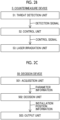
- the countermeasure device 5 includes a threat detection unit 51, a control unit 52, and a laser irradiation unit 53.
- the threat detection unit 51 detects the threat 4 and generates and outputs a detection signal representing a position of the threat 4.
- the control unit 52 controls the laser irradiation unit 53 based on the detection signal.
- the laser irradiation unit 53 counters the threat 4 with the laser irradiation under the control of the control unit 52.
- the decision device 50 includes an acquisition unit 501, a decision unit 502, and an output unit 503.
- the decision device 50 may be configured as, for example, a so-called computer that realizes a desired process by a calculation device executing a program.
- the acquisition unit 501 acquires a parameter group related to an environment around the countermeasure device 5, and transmits parameter information representing the acquired parameter group to the decision unit 502.
- the decision unit 502 decides a position where the blocking device 6 is installed, based on this parameter group.
- installation position information representing the installation position of the blocking device 6 is output so as to be transmitted to a worker who installs the blocking device 6.
- the decision device 50 may be separated from the countermeasure device 5 as in the example of Fig. 2A , or may be integrated into the countermeasure device 5.
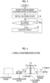
- a configuration example of the threat countermeasure method according to an embodiment will be described with reference to a flowchart of Fig. 3 .
- an operation example of the threat countermeasure system 1 according to an embodiment will be described with reference to the flowchart of Fig. 3 .
- step S1 is executed.
- the decision device 50 decides the position where the blocking device 6 is installed.
- the acquisition unit 501 of the decision device 50 acquires the parameter group related to the environment around the countermeasure device 5.
- This parameter group includes, for example, the refractive index structure constant Cn 2 indicating the degree of atmospheric fluctuation in the striking range space in which the laser beam emitted by the countermeasure device 5 propagates up to the threat 4.
- the acquisition unit 501 may include a measurement device group that measures this parameter group, or may include a communication device that receives, from the outside, a signal representing the parameter group measured by an external measurement device group.
- the acquisition unit 501 transmits the parameter information representing the acquired parameter group to the decision unit 502.
- the decision unit 502 of the decision device 50 specifies a position and a range of the block region 20 in which the blocking device 6 blocks the region passage of the threat 4, based on the parameter group represented by the received parameter information.
- the block region 20 may be decided, for example, as a region where the refractive index structure constant Cn 2 of the atmosphere in the region is presumed to be larger than a predetermined threshold value, that is, may be a region where the lethality of the laser beam is presumed to be lower than the predetermined threshold value for a reason such as insufficient focusing of the emitted laser beam due to the influence of atmospheric fluctuation, or may include this region.
- the block region 20 it may be considered that the refractive index structure constant Cn 2 changes with time, a weather condition, or the like.
- the block region 20 may be decided in consideration of a time, weather condition, or the like at which the refractive index structure constant Cn 2 is maximized, or may be decided in consideration of an appearance probability of the refractive index structure constant Cn 2 based on statistics or a simulation.
- the decision unit 502 further decides the position where the blocking device 6 is installed, based on the upper end of the block region 20.
- the position of the blocking device 6 includes the position of the upper end of the blocking device 6.
- An altitude of the position of the upper end of the blocking device 6 may be, for example, the same altitude as the upper end of the block region 20, or an altitude higher than the upper end of the block region 20 by a predetermined distance.
- a lower end of the blocking device 6 may be in contact with the ground 2, or may be separated from the ground 2 to such an extent as to block the passage of the threat 4 under the blocking device 6.
- the position of the blocking device 6 may be decided in consideration of a distance from the laser irradiation unit 53 to the threat 4.
- the lethality of the laser beam sufficient to counter the threat 4 may be maintained and thus it may not be necessary to block the threat 4 with the blocking device 6.
- the installation position information representing the installation position of the blocking device 6 is output so as to be transmitted to the worker who installs the blocking device 6.
- the output unit 503 may include a display device and display the installation position information on the display device, or may include a communication device and transmit the installation position information to a communication terminal owned by the worker.
- Step S2 is executed after step S1.
- the worker installs the blocking device 6 at the position decided in step S1.
- the blocking device 6 is configured to block the passage of the threat 4 through the block region 20.
- the blocking device 6 may be a net installed in the air. It is preferable that a mesh of the net is sufficiently narrow such that the drone as the threat 4 cannot pass through. Further, the net may be made of a material having a sufficiently high transmittance to the laser beam in order to suppress damage caused by the laser irradiation of the countermeasure device 5.
- the blocking device 6 may include a column or the like for installing the net in the air.
- Step S3 is executed after step S2.
- the threat detection unit 51 of the countermeasure device 5 determines whether or not the threat 4 is detected. After that, the threat detection unit 51 transmits the detection signal representing a determination result to the control unit 52.
- the detection signal includes threat position information representing the position of the threat 4, and the process proceeds to step S4.
- the process repeats step S3. In other words, step S3 is repeated until the threat detection unit 51 detects the threat 4.
- the threat 4 that comes flying to approach the protection target 3 initially moves along a path 71A having a relatively low altitude.
- the reason is that in a case where the threat 4 flies in a place where the altitude is low, as compared with a place where the altitude is high, a radar or the like is difficult to detect the threat 4.
- the reason is that the laser beam is difficult to be focused in a place close to the ground 2, as compared with a place far from the ground 2, due to a high degree of atmospheric fluctuation, that is, it is difficult to increase the lethality of the laser irradiation, and as a result, it is difficult to counter the threat 4 with the laser irradiation.
- the threat 4 that initially comes flying along the path 71A having a relatively low altitude increases the altitude along a path 71B to bypass the blocking device 6. Further, it is presumed that the threat 4 subsequently passes over the blocking device 6 along a path 71C, lowers the altitude along a path 71D, and attempts to approach the protection target 3 along a path 71E having a relatively low altitude.
- the altitude of the threat 4 is caused to be raised above the upper end of the blocking device 6, and thus it is possible to guide the threat 4 to a region, including the path 71C, where the degree of atmospheric fluctuation is low.
- step S4 of the flowchart of Fig. 3 the laser irradiation unit 53 of the countermeasure device 5 emits the laser beam to counter the threat 4.
- the control unit 52 transmits a control signal including the threat position information to the laser irradiation unit 53.
- the laser irradiation unit 53 emits the laser beam to the threat 4 in accordance with the control signal.
- the laser irradiation unit 53 may automatically perform, according to the control signal, an operation of directing an optical axis direction of the emitted laser beam toward the threat 4 and an operation of focusing the laser beam at the position of the threat 4. Further, an operation of actually emitting the laser beam by the laser irradiation unit 53 may be performed under the control of the worker.
- the laser irradiation unit 53 can counter and neutralize the threat 4 with the laser irradiation having the lethality higher than the predetermined threshold value, which is obtained by focusing the laser beam with sufficient accuracy.
- the laser irradiation unit 53 can counter the threat 4 with the laser irradiation having a sufficiently high lethality. In this case, a part of the laser beam may be emitted to the blocking device 6. However, in a case where a transmittance of a material constituting the blocking device 6 to the laser beam is sufficiently high, damage to the blocking device 6 due to the laser irradiation is suppressed. In this case, in step S1 of the flowchart of Fig.
- the installation position of the blocking device 6 may be decided, further based on a distance from the countermeasure device 5, such that the lethality of the laser beam emitted by the laser irradiation unit 53 of the countermeasure device 5 is larger than the predetermined threshold value on an inner side of the block region 20.
- This threshold value is, for example, the lethality that the laser beam is presumed to neutralize the threat 4 on the inner side of the block region 20.
- a position in the block region 20 where the lethality of the laser beam exceeds the threshold value may be set as a limit of a relative distance from the countermeasure device 5 to the blocking device 6.
- the laser irradiation unit 53 may counter the threat 4 with the laser irradiation.
- the threat 4 is in the block region 20
- the distance from the laser irradiation unit 53 to the threat 4 is relatively long
- the blocking device 6 is installed between the laser irradiation unit 53 and the threat 4.
- the lethality of the laser irradiation may be low as compared with a case where the case where the threat 4 flies along the paths 71C, 71D, and 71E. Nevertheless, the longer the threat 4 flies to approach the protection target 3, the more damage to the threat 4 caused by the laser irradiation accumulates.
- step S4 of the flowchart of Fig. 3 the process returns to step S3 in order to detect and counter another threat 4.
- the threat countermeasure system 1 and the threat countermeasure method according to an embodiment can efficiently counter the incoming threat 4 with the laser irradiation.
- the configuration has been described in which the blocking device 6 is installed so as to block the passing of the threat 4 through the block region 20.
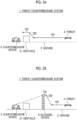
- a configuration will be described in which the blocking device 6 is installed in order to counter the threat 4 flying in a space hidden behind an obstacle as viewed from the countermeasure device 5.
- the block region 20 includes, for example, a space included in a blind spot behind the obstacle as viewed from the countermeasure device 5.
- the threat 4 flies along a path 72A having a relatively low altitude, increases the altitude along a path 72B to bypass the obstacle 31, and passes over the obstacle 31 along a path 72C.
- the threat 4 is in the blind spot of the obstacle 31 as viewed from the countermeasure device 5 while the threat 4 flies along the paths 72A and 72B.
- the countermeasure device 5 can counter the threat 4 with the laser irradiation in a case where the threat 4 passes over the obstacle 31.
- the countering against the threat 4 may not always be in time.
- the blocking device 6 is installed between the obstacle 31 and the threat 4. With the installation therebetween, the threat 4 flies along a path 73A having a relatively low altitude, increases the altitude along a path 73B to bypass the blocking device 6, and passes over the blocking device 6 along a path 73C. In this case, the threat 4 flying along the path 73C is not in the blind spot of the obstacle 31 as viewed from the countermeasure device 5, and the distance from the countermeasure device 5 to the threat 4 is relatively long. Therefore, the countering against the threat 4 is in time.
- the position of the blocking device 6 is decided such that the countermeasure device 5 can counter, in a case where the threat 4 passes over the blocking device 6, the threat 4 with the laser irradiation having the lethality passing over a predetermined height, and the blocking device 6 is installed.
- the configuration has been described in which the obstacle 31 is present between the countermeasure device 5 and the threat 4.
- a configuration will be described in which the blocking device 6 is installed in order for the countermeasure device 5 to counter the threat 4, with reference to the examples of Figs. 6A and 6B .
- the lethality of the laser irradiation by the countermeasure device 5 against the threat 4 is zero.
- the blocking device 6 is installed between the countermeasure device 5 and the threat 4. With the installation therebetween, the threat 4 flies along a path 75A having a relatively low altitude, increases the altitude along a path 75B to bypass the blocking device 6, and passes over blocking device 6 along a path 75C. After that, the threat 4 lowers the altitude along a path 75D to approach the countermeasure device 5 along a path 75E having a relatively low altitude. In this case, there is no obstacle 32 in the space behind the threat 4 flying along the path 75C as viewed from the countermeasure device 5. Therefore, the countermeasure device 5 can counter the threat 4 with the laser irradiation without emitting the laser beam to the obstacle 32.
- the position of the blocking device 6 is decided such that the countermeasure device 5 can counter, in a case where the threat 4 passes over the blocking device 6, the threat 4 with the laser irradiation having the lethality passing over a predetermined height, and the blocking device 6 is installed.
- the configuration has been described in which the installation position of the blocking device 6 is decided on the premise that the area of the block region 20 projected onto the ground 2 is relatively large, the length of the blocking device 6 projected onto the ground 2 is relatively long, and thus the threat 4 passes over the blocking device 6 from above to bypass the blocking device 6.
- a configuration will be described in which the installation position of the blocking device 6 is decided on the premise that the threat 4 may bypass the blocking device 6 from a side, with reference to the example of Fig. 7 .
- the length of the blocking device 6 projected onto the ground 2 can be relatively short. In other words, it is possible to suppress costs of installing and maintaining the blocking device 6 according to the scale of the block region 20.
- the incoming threat 4 bypasses the blocking device 6 from the side more easily, as compared with the case where the length of the blocking device 6 projected onto the ground 2 is relatively long, in order for the incoming threat 4 to bypass the blocking device 6.
- a position of a lateral end portion of the blocking device 6 is decided such that the laser beam does not pass through the block region 20, and the blocking device 6 is installed.
- the configuration has been described in which the blocking device 6 is the net made of the material having the relatively high transmittance to the laser beam.
- this configuration a case will be described where another configuration is used as the blocking device 6.
- a plate-shaped object having a relatively high transmittance to the laser beam may be installed on the ground 2 so as to block the passage of the threat 4, and may be used as the blocking device 6.
- one or more columns may be used to support the plate-shaped object.
- a plurality of columnar objects having a relatively high transmittance to the laser beam may be installed on the ground 2 at spacings so as to block the passage of the threat 4, and may be used as the blocking device 6.
- a net, a plate-shaped object, or a columnar object made of a material that is relatively less damaged even in a case of being emitted by the laser beam is installed on the ground 2 so as to block the passage of the threat 4, and may be used as the blocking device 6.
- a barbed iron wire may be used as the blocking device 6.
- a net, a plate-shaped object, or a columnar object made of a flame-retardant material that is hard to burn even in a case of being emitted by the laser beam is installed on the ground 2 so as to block the passage of the threat 4, and may be used as the blocking device 6.
- the flame-retardant material includes, for example, vinyl chloride.
- the blocking device 6 that blocks the passage of the threat 4 by continuing to move may be used.
- an air curtain generator, a fan, or the like may be installed as the blocking device 6 so as to block the flight of the threat 4 by causing a wind.
- a shutter, a fan, or the like that partially obstructs a range in which the passage of the threat 4 is desired to be blocked may be used as the blocking device 6. In this case, the shutter or the fan moves so as to obstruct, in a time division, the entire range in which the passage of the threat 4 is desired to be blocked.
- a moving speed of a blade of the shutter or the fan is set, according to a flight speed of the threat 4, such that the blade of the shutter or the fan arrives, before the threat 4 passes through a range in which the blade of the shutter or the fan is not present, at the range to block the passage of the threat 4.
- the blocking device 6 is installed so as to be fixed to the ground 2.
- a configuration will be described in which a part or the whole of the blocking device 6 is installed in a state of being suspended from the sky, with reference to the examples of Figs. 8 and 9 .
- the threat countermeasure system 1 according to the present embodiment shown in the example of Fig. 8 is obtained by adding the following changes to the threat countermeasure system 1 according to the first embodiment shown in Fig. 2A . That is, the blocking device 6 includes a defective portion 60, and the threat countermeasure system 1 further includes another blocking device 62 that closes the defective portion 60 and a drone 61 that supports the blocking device 62 in a suspended state from the sky.
- the number of drones 61 may be plural.
- the blocking device 62 different from the blocking device 6 is further installed to block the passage of the threat 4 through the defective portion 60 to approach the protection target 3.
- the blocking device 62 may be suspended, near the defective portion 60, by the drone 61 that stands by in a hovering state.
- the presence and position of the defective portion 60 of the blocking device 6 is detected by the acquisition unit 501 of the decision device 50.
- the decision unit 502 of the decision device 50 may decide to close the defective portion 60 with the blocking device 62, and the output unit 503 of the decision device 50 may control the drone 61 in a state where the blocking device 62 is suspended to guide the drone 61 to the position of the defective portion 60.
- the countermeasure device 5 can counter the threat 4 with the laser irradiation.
- the threat countermeasure system 1 with the closing of the defective portion 60 by another blocking device 62 in a case where the blocking device 6 is partially damaged, it is possible to block the passage of the threat 4 through the defective portion 60 without replacing or repairing the blocking device 6.
- the entire blocking device 6 is installed in the air by the drone 61.
- the number of drones 61 may be plural.
- such a configuration is effective in a case, or the like, where the protection target 3 and the countermeasure device 5 are located on a ground 21 on a cliff and the threat 4 flies at a relatively low altitude along a path 78A from a ground 22 under the cliff.
- a range 8 is too close to the countermeasure device 5 to install the blocking device 6 on the ground 21, and there may be no sufficient time for the countermeasure device 5 to counter the threat 4 after the threat 4 reaches the sky above the ground 21.
- a dimension of the blocking device 6 in a height direction may not reach a desired height. Even in such a case, it is possible to install the entire blocking device 6 in the air such that the upper end of the blocking device 6 reaches a desired altitude.
- the blocking device 6 it is possible to install the blocking device 6 not only on a flat ground but also on various terrains.
- the configuration has been described in which the threat detection unit 51 of the countermeasure device 5 detects the incoming threat 4.
- a configuration will be described in which the countermeasure device 5 starts the countering against the threat 4 more quickly by detection of the threat 4 using a remote sensor installed at a position away from the countermeasure device 5, with reference to Figs. 10 and 11 .
- the threat countermeasure system 1 according to the present embodiment shown in the example of Fig. 10 is obtained by adding the obstacle 31 to the threat countermeasure system 1 shown in Fig. 2A .
- the obstacle 31 hinders the detection of the threat 4 in the blind spot of the obstacle 31 as viewed from the countermeasure device 5 by the threat detection unit 51 of the countermeasure device 5.
- the threat 4 flies along a path 79A having a relatively low altitude from the ground 2, increases the altitude along a path 79B to bypass the blocking device 6, and passes over the blocking device 6 along a path 79C.
- the threat 4 is in the blind spot of the obstacle 31 as viewed from the countermeasure device 5, and thus the countermeasure device 5 may not yet be able to counter the threat 4.
- the threat 4 lowers the altitude along a path 79D, flies along a path 79E having a relatively low altitude from the ground 2, increases the altitude along a path 79F to bypass the obstacle 31, and passes over the obstacle 31 along a path 79G.
- the threat detection unit 51 of the countermeasure device 5 detects the threat 4 for the first time at this moment, the countering against the threat 4 with the laser irradiation by the laser irradiation unit 53 of the countermeasure device 5 may not always be in time.
- a remote sensor 9 detecting the threat 4 is installed in a place where the threat 4 that comes flying from a space hidden behind the blocking device 6 does not enter the blind spot of the obstacle 31, as viewed from the countermeasure device 5.
- the remote sensor 9 may be further installed at a place closer to the blocking device 6 than the countermeasure device 5.
- the remote sensor 9 transmits a remote detection signal representing the position of the threat 4 to the threat detection unit 51 of the countermeasure device 5.
- the threat detection unit 51 includes a communication device that receives the remote detection signal, and transmits the position of the threat 4 represented by the remote detection signal to the control unit 52. In this manner, before the threat 4 approaches too close to the countermeasure device 5, for example, at a point in time at which the threat 4 passes over the blocking device 6 along the path 79C, the countermeasure device 5 can counter the threat 4 with the laser irradiation.
- the block region 20 includes, for example, a space included in the blind spot behind the obstacle 31 as viewed from the countermeasure device 5.
- the remote sensor 9 used in the third embodiment may be introduced. A case where the threat detection capability of a threat countermeasure system is lowered due to the influence of the blocking device 6 or a case where the threat detection at a long distance is insufficient can be compensated for.
- the threat countermeasure system 1 and the threat countermeasure method described in each embodiment are grasped as follows, for example.
- an effect is achieved that it is possible to guide the threat 4 to the outer side of the block region 20 with the blocking device 6 to counter the threat 4 with the laser irradiation.
- the threat countermeasure system 1 according to a second aspect is the threat countermeasure system 1 according to the first aspect, in which the block region 20 includes a space in which a refractive index structure constant Cn 2 is larger than a predetermined threshold value.
- the threat countermeasure system 1 with the guiding of the threat 4 to the outer side of the block region 20 where the lethality of laser irradiation is reduced due to a large degree of atmospheric fluctuation, an effect is achieved that it is possible to counter the threat 4 with the laser irradiation in a space in which the lethality of laser irradiation is sufficiently high.
- the threat countermeasure system 1 according to a third aspect is the threat countermeasure system 1 according to the first aspect, in which the block region 20 includes a space which is included in a blind spot as viewed from the countermeasure device 5.
- an effect is achieved that, with the guiding of the threat 4 to the outer side of the block region 20 included in the blind spot as viewed from the countermeasure device 5, it is possible to counter the threat 4 with the laser irradiation.
- the threat countermeasure system 1 according to a fourth aspect is the threat countermeasure system 1 according to the first aspect, in which the block region 20 is in front of an obstacle 32 as viewed from the countermeasure device 5.
- the threat countermeasure system 1 according to a fifth aspect is the threat countermeasure system 1 according to the first to fourth aspects, and further includes a drone 61 that suspends and supports the blocking device 6.
- the threat countermeasure system 1 according to a sixth aspect is the threat countermeasure system 1 according to the first to fourth aspects, and further includes another blocking device 62 and a drone 61.
- the other blocking device 62 is installed to compensate for a defective portion 60 of the blocking device 6.
- the drone 61 suspends and supports the other blocking device 62.
- the threat countermeasure system 1 according to a seventh aspect is the threat countermeasure system 1 according to the first to sixth aspects, in which the countermeasure device 5 includes a threat detection unit 51, a laser irradiation unit 53, and a control unit 52.
- the threat detection unit 51 detects the threat 4 and outputs a detection signal representing a position of the threat 4.
- the laser irradiation unit 53 counters the threat 4 with the laser irradiation.
- the control unit 52 controls the laser irradiation unit 53 based on the detection signal.
- the threat countermeasure system 1 according to an eighth aspect is the threat countermeasure system 1 according to the seventh aspect, and further includes a remote sensor 9.
- the remote sensor 9 is installed away from the countermeasure device 5, detects the threat 4, and outputs a remote detection signal representing a position of the threat 4.
- the control unit 52 controls the laser irradiation unit 53 further based on the remote detection signal.
- a threat countermeasure method includes deciding a position of an upper end of a blocking device 6 based on an upper end of a block region 20 in which lethality of laser irradiation is presumed to be lower than a predetermined threshold value, installing the blocking device 6 to block passage of an incoming threat 4 through the block region 20 to approach a protection target 3, and detecting the threat 4 to counter the threat 4 with the laser irradiation.
- an effect is achieved that it is possible to guide the threat 4 to the outer side of the block region 20 with the blocking device 6 to counter the threat 4 with the laser irradiation.
Landscapes
- Engineering & Computer Science (AREA)
- Remote Sensing (AREA)
- Aviation & Aerospace Engineering (AREA)
- Radar, Positioning & Navigation (AREA)
- General Engineering & Computer Science (AREA)
- Physics & Mathematics (AREA)
- Optics & Photonics (AREA)
- Mechanical Engineering (AREA)
- Optical Radar Systems And Details Thereof (AREA)
Abstract
Description
- The present invention relates to a threat countermeasure system and a threat countermeasure method, and for example, the present invention can be suitably used for a countermeasure against an incoming threat.
- In recent years, a technique related to an unmanned aerial vehicle (UAV) such as a drone has been advanced and has become a threat in defending a protection target. In response to such a threat, a threat countermeasure system has been considered in which a high-output laser beam is caused to propagate into the atmosphere and is emitted to the threat to remotely destroy a target. The high-output laser beam driven by electricity can continue to counter the threat as long as a power source can be secured, and costs thereof are low as compared with a case where a bombshell, a missile, or the like is used.
- On the other hand, it is conceivable that an aerial threat such as a drone flies at a low altitude near a ground such that the aerial threat is difficult to be detected by a radar or the like. In general, in the air near the ground, a degree of atmospheric fluctuation is larger than in the sky at a higher altitude. In particular, in a case where the ground receives strong sunlight in fine weather, the degree of atmospheric fluctuation of the air near the ground increases. A refractive index structure constant Cn2 (unit: m-2/3) is one of indexes for measuring the degree of atmospheric fluctuation. The degree of atmospheric fluctuation is larger as the refractive index structure constant Cn2 is larger.
- In a case where the degree of atmospheric fluctuation is large, it becomes difficult to focus the laser beam, and lethality of the laser beam against the target is reduced. As a result, in a case where the aerial threat flies at a low altitude near the ground, the lethality of the laser beam against the aerial threat may be reduced as compared with a case where the aerial threat flies in the sky.
- In relation to the above, PTL 1 (
Japanese Patent No. 5960934 PTL 1 is means for physically protecting a protection target on an inner side thereof from an attack from the sky on an outer side thereof, and does not take into consideration a countermeasure by laser irradiation, the influence of atmospheric fluctuation in a low altitude, or the like. - Further, PTL 2 (
Japanese Patent No. 6413057 PTL 2 are means for restraining a target with a restraint network ejected from the unmanned aerial vehicle, and do not take into consideration a countermeasure by laser irradiation, the influence of atmospheric fluctuation in a low altitude, or the like. - Further, PTL 3 (
Japanese Unexamined Patent Application Publication No. 2019-60589 - Further, PTL 4 (
PCT Japanese Translation Patent Publication No. 2020-519843 PTL 4 is means for capturing a target by launching a net or the like from an aircraft of ally, and does not take into consideration a countermeasure by laser irradiation, the influence of atmospheric fluctuation in a low altitude, or the like. - Further, PTL 5 (
Japanese Unexamined Patent Application Publication No. 2021-014958 PTL 5 emits a laser beam to counter a threat, but does not take into consideration the influence of atmospheric fluctuation on the laser beam, blocking of flying of the threat at a low altitude, or the like. -
- [PTL 1]
Japanese Patent No. 5960934 - [PTL 2]
Japanese Patent No. 6413057 - [PTL 3]
Japanese Unexamined Patent Application Publication No. 2019-60589 - [PTL 4] PCT Japanese Translation Patent Publication No. 2020-519843
- [PTL 5]
Japanese Unexamined Patent Application Publication No. 2021-014958 - In view of the above circumstances, one of purposes of the present disclosure is to provide a threat countermeasure system and a threat countermeasure method that efficiently counter an incoming threat with laser irradiation. Other issues and novel features will become apparent from description and accompanying drawings of the present specification.
- According to an embodiment, a threat countermeasure system includes a countermeasure device, a blocking device, and a decision device. The countermeasure device detects an incoming threat and counters the threat with laser irradiation. The blocking device is installed so as to block the approach of the threat to a protection target through a block region in which lethality of the laser irradiation is presumed to be lower than a predetermined threshold value. The decision device decides a position of an upper end of the blocking device based on an upper end of the block region.
- According to an embodiment, a threat countermeasure method includes deciding a position of an upper end of a blocking device based on an upper end of a block region in which lethality of laser irradiation is presumed to be lower than a predetermined threshold value, installing the blocking device to block passage of an incoming threat through the block region to approach a protection target, and detecting the threat to counter the threat with the laser irradiation.
- According to an embodiment, it is possible to efficiently counter the incoming threat with the laser irradiation.
-
-
Fig. 1 is a diagram showing a configuration example of a threat countermeasure system in the related art. -
Fig. 2A is a diagram showing a configuration example of a threat countermeasure system according to an embodiment. -
Fig. 2B is a diagram showing a configuration example of a countermeasure device according to an embodiment. -
Fig. 2C is a diagram showing a configuration example of a decision device according to an embodiment. -
Fig. 3 is a flowchart showing a configuration example of a threat countermeasure method according to an embodiment. -
Fig. 4 is a diagram showing an operation example of the threat countermeasure system according to an embodiment. -
Fig. 5A is a diagram for describing a modification example of the threat countermeasure system according to an embodiment. -
Fig. 5B is a diagram for describing a modification example of the threat countermeasure system according to an embodiment. -
Fig. 6A is a diagram for describing a modification example of the threat countermeasure system according to an embodiment. -
Fig. 6B is a diagram for describing a modification example of the threat countermeasure system according to an embodiment. -
Fig. 7 is a diagram showing a modification example of the threat countermeasure system according to the embodiment. -
Fig. 8 is a diagram showing a configuration example of the threat countermeasure system according to an embodiment. -
Fig. 9 is a diagram showing a configuration example of the threat countermeasure system according to an embodiment. -
Fig. 10 is a diagram showing a configuration example of the threat countermeasure system according to an embodiment. -
Fig. 11 is a diagram showing a configuration example of the threat countermeasure system according to an embodiment. - Embodiments for implementing a threat countermeasure system and a threat countermeasure method according to the present disclosure will be described below with reference to accompanying drawings.
- In order to better understand the issues, a threat countermeasure system in the related art will be described first. As shown in
Fig. 1 , athreat countermeasure system 101 in the related art includes acountermeasure device 105 installed on aground 102. In order to defend aprotection target 103, thecountermeasure device 105 countersincoming threats threat 104A passing through apath 107A having a relatively high altitude is focused with sufficient accuracy to counter thethreat 104A. As an example, in a case where thethreat 104A is a multicopter type drone including a plurality of rotor blades, thecountermeasure device 105 performs the countering such that the rotor blade included in thethreat 104A, a computer circuit for controlling thethreat 104A, or the like is heated by energy of the focused laser beam and thus falls into malfunction or structural destruction. - On the other hand, the air in a space relatively close to the
ground 102 is likely to generate atmospheric fluctuation, such as heat haze, due to being heated by theground 102 or the like, and the laser beam is more difficult to be focused as a degree of atmospheric fluctuation is larger. Therefore, even though there is an attempt to counter thethreat 104B passing through apath 107B having a relatively low altitude with the laser irradiation, lethality of the laser beam emitted to thethreat 104B may be insufficient. In other words, the lethality of the laser beam needs to reach a predetermined threshold value in order to cause thethreat 104B to fall into malfunction or structural destruction. In a case where the lethality of the laser beam that is not sufficiently focused due to the influence of atmospheric fluctuation or the like is lower than the threshold value, it is difficult to counter thethreat 104B with the laser irradiation. - The degree of atmospheric fluctuation can be represented, for example, as a refractive index structure constant Cn2. As the refractive index structure constant Cn2 is larger, the degree of atmospheric fluctuation is larger, a degree of focusing of the laser beam is lower, and the lethality of the laser beam against the
threat 104B is smaller. A second threshold value is defined for the refractive index structure constant Cn2 in correspondence with a first threshold value at which the lethality of the laser beam is sufficient to counter thethreat 104B. In a case where the first threshold value is provided, the second threshold value can be obtained and defined with calculation of the lethality of the laser beam. Characteristics of athreat countermeasure system 1, such as the power, wavelength, and divergence angle of the laser beam and the aiming accuracy of thethreat countermeasure system 1, a distance of the threat, an atmospheric transmission rate, and the like may be used in the calculation of the lethality of the laser beam. Further, the second threshold value may be empirically set from a test result relating to the lethality of the laser beam or the like. - As shown in
Fig. 2A , thethreat countermeasure system 1 according to an embodiment includes acountermeasure device 5, ablocking device 6, and adecision device 50. Thecountermeasure device 5 detects theincoming threats threat 4A that flies along apath 70A passing over the blockingdevice 6. Theblocking device 6 is installed at a position where thethreats block region 20 in which the lethality of the laser irradiation is presumed to be lower than the predetermined threshold value and approaching aprotection target 3. For example, the passage of thethreat 4B flying along apath 70B below an upper end of theblocking device 6 is blocked. Thethreat 4A bypasses theblocking device 6 to move, and as a result, passes through a space on an outer side of theblock region 20 and on an inner side of a striking range of thecountermeasure device 5. Thedecision device 50 decides a position of the upper end of theblocking device 6 based on an upper end of theblock region 20. Here, a case will be described, as an example, in which since an area of theblock region 20 projected onto aground 2 is relatively large, a length of theblocking device 6 projected onto theground 2 is relatively long with respect to a height of theblocking device 6 in a direction orthogonal to an incoming direction of thethreat 4B, and thus thethreat 4B is presumed to pass over the blockingdevice 6 from above in order to bypass theblocking device 6. Hereinafter, in a case where thethreats threat 4. - As shown in
Fig. 2B , thecountermeasure device 5 according to an embodiment includes athreat detection unit 51, acontrol unit 52, and alaser irradiation unit 53. Thethreat detection unit 51 detects thethreat 4 and generates and outputs a detection signal representing a position of thethreat 4. Thecontrol unit 52 controls thelaser irradiation unit 53 based on the detection signal. Thelaser irradiation unit 53 counters thethreat 4 with the laser irradiation under the control of thecontrol unit 52. - As shown in
Fig. 2C , thedecision device 50 according to an embodiment includes anacquisition unit 501, adecision unit 502, and anoutput unit 503. Thedecision device 50 may be configured as, for example, a so-called computer that realizes a desired process by a calculation device executing a program. Theacquisition unit 501 acquires a parameter group related to an environment around thecountermeasure device 5, and transmits parameter information representing the acquired parameter group to thedecision unit 502. Thedecision unit 502 decides a position where theblocking device 6 is installed, based on this parameter group. In theoutput unit 503, installation position information representing the installation position of theblocking device 6 is output so as to be transmitted to a worker who installs theblocking device 6. Thedecision device 50 may be separated from thecountermeasure device 5 as in the example ofFig. 2A , or may be integrated into thecountermeasure device 5. - A configuration example of the threat countermeasure method according to an embodiment will be described with reference to a flowchart of
Fig. 3 . In other words, an operation example of thethreat countermeasure system 1 according to an embodiment will be described with reference to the flowchart ofFig. 3 . - In a case where a process of the flowchart of
Fig. 3 is started, step S1 is executed. In step S1, thedecision device 50 decides the position where theblocking device 6 is installed. - First, the
acquisition unit 501 of thedecision device 50 acquires the parameter group related to the environment around thecountermeasure device 5. This parameter group includes, for example, the refractive index structure constant Cn2 indicating the degree of atmospheric fluctuation in the striking range space in which the laser beam emitted by thecountermeasure device 5 propagates up to thethreat 4. For example, theacquisition unit 501 may include a measurement device group that measures this parameter group, or may include a communication device that receives, from the outside, a signal representing the parameter group measured by an external measurement device group. Theacquisition unit 501 transmits the parameter information representing the acquired parameter group to thedecision unit 502. - Next, the
decision unit 502 of thedecision device 50 specifies a position and a range of theblock region 20 in which theblocking device 6 blocks the region passage of thethreat 4, based on the parameter group represented by the received parameter information. Theblock region 20 may be decided, for example, as a region where the refractive index structure constant Cn2 of the atmosphere in the region is presumed to be larger than a predetermined threshold value, that is, may be a region where the lethality of the laser beam is presumed to be lower than the predetermined threshold value for a reason such as insufficient focusing of the emitted laser beam due to the influence of atmospheric fluctuation, or may include this region. In a case where theblock region 20 is decided, it may be considered that the refractive index structure constant Cn2 changes with time, a weather condition, or the like. For example, theblock region 20 may be decided in consideration of a time, weather condition, or the like at which the refractive index structure constant Cn2 is maximized, or may be decided in consideration of an appearance probability of the refractive index structure constant Cn2 based on statistics or a simulation. Thedecision unit 502 further decides the position where theblocking device 6 is installed, based on the upper end of theblock region 20. The position of theblocking device 6 includes the position of the upper end of theblocking device 6. An altitude of the position of the upper end of theblocking device 6 may be, for example, the same altitude as the upper end of theblock region 20, or an altitude higher than the upper end of theblock region 20 by a predetermined distance. A lower end of theblocking device 6 may be in contact with theground 2, or may be separated from theground 2 to such an extent as to block the passage of thethreat 4 under theblocking device 6. The position of theblocking device 6 may be decided in consideration of a distance from thelaser irradiation unit 53 to thethreat 4. In a case where the distance from thelaser irradiation unit 53 to thethreat 4 is short even though the refractive index structure constant Cn2 is large, the lethality of the laser beam sufficient to counter thethreat 4 may be maintained and thus it may not be necessary to block thethreat 4 with theblocking device 6. - Next, in the
output unit 503 of thedecision device 50, the installation position information representing the installation position of theblocking device 6 is output so as to be transmitted to the worker who installs theblocking device 6. For example, theoutput unit 503 may include a display device and display the installation position information on the display device, or may include a communication device and transmit the installation position information to a communication terminal owned by the worker. - Step S2 is executed after step S1. In step S2, the worker installs the
blocking device 6 at the position decided in step S1. Theblocking device 6 is configured to block the passage of thethreat 4 through theblock region 20. As an example, in a case where thethreat 4 is a drone, the blockingdevice 6 may be a net installed in the air. It is preferable that a mesh of the net is sufficiently narrow such that the drone as thethreat 4 cannot pass through. Further, the net may be made of a material having a sufficiently high transmittance to the laser beam in order to suppress damage caused by the laser irradiation of thecountermeasure device 5. Theblocking device 6 may include a column or the like for installing the net in the air. - Step S3 is executed after step S2. In step S3, the
threat detection unit 51 of thecountermeasure device 5 determines whether or not thethreat 4 is detected. After that, thethreat detection unit 51 transmits the detection signal representing a determination result to thecontrol unit 52. In a case where thethreat detection unit 51 detects the threat 4 (Yes), the detection signal includes threat position information representing the position of thethreat 4, and the process proceeds to step S4. On the contrary, in a case where thethreat detection unit 51 does not detect the threat 4 (No), the process repeats step S3. In other words, step S3 is repeated until thethreat detection unit 51 detects thethreat 4. - As shown in
Fig. 4 , thethreat 4 that comes flying to approach theprotection target 3 initially moves along apath 71A having a relatively low altitude. The reason is that in a case where thethreat 4 flies in a place where the altitude is low, as compared with a place where the altitude is high, a radar or the like is difficult to detect thethreat 4. Further, the reason is that the laser beam is difficult to be focused in a place close to theground 2, as compared with a place far from theground 2, due to a high degree of atmospheric fluctuation, that is, it is difficult to increase the lethality of the laser irradiation, and as a result, it is difficult to counter thethreat 4 with the laser irradiation. - However, it is presumed that the
threat 4 that initially comes flying along thepath 71A having a relatively low altitude increases the altitude along apath 71B to bypass theblocking device 6. Further, it is presumed that thethreat 4 subsequently passes over the blockingdevice 6 along apath 71C, lowers the altitude along apath 71D, and attempts to approach theprotection target 3 along apath 71E having a relatively low altitude. As described above, with the threat countermeasure method according to an embodiment, due to the installation of theblocking device 6 at an appropriate position, the altitude of thethreat 4 is caused to be raised above the upper end of theblocking device 6, and thus it is possible to guide thethreat 4 to a region, including thepath 71C, where the degree of atmospheric fluctuation is low. - In step S4 of the flowchart of
Fig. 3 , thelaser irradiation unit 53 of thecountermeasure device 5 emits the laser beam to counter thethreat 4. First, thecontrol unit 52 transmits a control signal including the threat position information to thelaser irradiation unit 53. Next, thelaser irradiation unit 53 emits the laser beam to thethreat 4 in accordance with the control signal. In this case, thelaser irradiation unit 53 may automatically perform, according to the control signal, an operation of directing an optical axis direction of the emitted laser beam toward thethreat 4 and an operation of focusing the laser beam at the position of thethreat 4. Further, an operation of actually emitting the laser beam by thelaser irradiation unit 53 may be performed under the control of the worker. - As shown in
Fig. 4 , in a case where thethreat 4 flies along thepath 71C, thethreat 4 is on the outer side of theblock region 20 in which the degree of atmospheric fluctuation is relatively high. Therefore, thelaser irradiation unit 53 can counter and neutralize thethreat 4 with the laser irradiation having the lethality higher than the predetermined threshold value, which is obtained by focusing the laser beam with sufficient accuracy. - In addition, in a case where the
threat 4 flies along thepaths threat 4 is in theblock region 20, the distance from thelaser irradiation unit 53 to thethreat 4 is relatively short. Therefore, thelaser irradiation unit 53 can counter thethreat 4 with the laser irradiation having a sufficiently high lethality. In this case, a part of the laser beam may be emitted to theblocking device 6. However, in a case where a transmittance of a material constituting theblocking device 6 to the laser beam is sufficiently high, damage to theblocking device 6 due to the laser irradiation is suppressed. In this case, in step S1 of the flowchart ofFig. 3 , the installation position of theblocking device 6 may be decided, further based on a distance from thecountermeasure device 5, such that the lethality of the laser beam emitted by thelaser irradiation unit 53 of thecountermeasure device 5 is larger than the predetermined threshold value on an inner side of theblock region 20. This threshold value is, for example, the lethality that the laser beam is presumed to neutralize thethreat 4 on the inner side of theblock region 20. In other words, a position in theblock region 20 where the lethality of the laser beam exceeds the threshold value may be set as a limit of a relative distance from thecountermeasure device 5 to theblocking device 6. - Further, in a case where the
threat 4 flies along thepaths laser irradiation unit 53 may counter thethreat 4 with the laser irradiation. In this case, thethreat 4 is in theblock region 20, the distance from thelaser irradiation unit 53 to thethreat 4 is relatively long, and theblocking device 6 is installed between thelaser irradiation unit 53 and thethreat 4. Thus, the lethality of the laser irradiation may be low as compared with a case where the case where thethreat 4 flies along thepaths threat 4 flies to approach theprotection target 3, the more damage to thethreat 4 caused by the laser irradiation accumulates. - After step S4 of the flowchart of
Fig. 3 , the process returns to step S3 in order to detect and counter anotherthreat 4. - As described above, the
threat countermeasure system 1 and the threat countermeasure method according to an embodiment can efficiently counter theincoming threat 4 with the laser irradiation. - In the above-described first embodiment, the configuration has been described in which the
blocking device 6 is installed so as to block the passing of thethreat 4 through theblock region 20. As a modification example of this configuration, with reference to the examples ofFigs. 5A and 5B , a configuration will be described in which theblocking device 6 is installed in order to counter thethreat 4 flying in a space hidden behind an obstacle as viewed from thecountermeasure device 5. In this case, theblock region 20 includes, for example, a space included in a blind spot behind the obstacle as viewed from thecountermeasure device 5. - As shown in the example of
Fig. 5A , in a case where anobstacle 31 is present between thecountermeasure device 5 and thethreat 4, it is difficult for thecountermeasure device 5 to counter thethreat 4 with the laser irradiation. In the example ofFig. 5A , thethreat 4 flies along apath 72A having a relatively low altitude, increases the altitude along apath 72B to bypass theobstacle 31, and passes over theobstacle 31 along apath 72C. Thethreat 4 is in the blind spot of theobstacle 31 as viewed from thecountermeasure device 5 while thethreat 4 flies along thepaths countermeasure device 5 to counter thethreat 4 with the laser irradiation. In other words, even though thecountermeasure device 5 attempts to counter thethreat 4 in the blind spot of theobstacle 31 with the laser irradiation, the lethality of the laser irradiation against thethreat 4 is insufficient or zero. On the other hand, thecountermeasure device 5 can counter thethreat 4 with the laser irradiation in a case where thethreat 4 passes over theobstacle 31. However, in this case, since the distance from thecountermeasure device 5 to thethreat 4 is relatively short, the countering against thethreat 4 may not always be in time. - In the present modification example, as shown in the example of
Fig. 5B , the blockingdevice 6 is installed between theobstacle 31 and thethreat 4. With the installation therebetween, thethreat 4 flies along apath 73A having a relatively low altitude, increases the altitude along apath 73B to bypass theblocking device 6, and passes over the blockingdevice 6 along apath 73C. In this case, thethreat 4 flying along thepath 73C is not in the blind spot of theobstacle 31 as viewed from thecountermeasure device 5, and the distance from thecountermeasure device 5 to thethreat 4 is relatively long. Therefore, the countering against thethreat 4 is in time. In other words, in the present modification example, the position of theblocking device 6 is decided such that thecountermeasure device 5 can counter, in a case where thethreat 4 passes over the blockingdevice 6, thethreat 4 with the laser irradiation having the lethality passing over a predetermined height, and theblocking device 6 is installed. - In the above modification example, the configuration has been described in which the
obstacle 31 is present between thecountermeasure device 5 and thethreat 4. As another modification example of the first embodiment, which is different from the above modification example, in a case where anobstacle 32 is present in a space behind thethreat 4 as viewed from thecountermeasure device 5, a configuration will be described in which theblocking device 6 is installed in order for thecountermeasure device 5 to counter thethreat 4, with reference to the examples ofFigs. 6A and 6B . - As shown in the example of
Fig. 6A , in a case where theobstacle 32 is present in the space behind thethreat 4 as viewed from thecountermeasure device 5 and it is not preferable to emit the laser beam to theobstacle 32, it is difficult for thecountermeasure device 5 to counter thethreat 4 with the laser irradiation. In a case where thethreat 4 moves toward thecountermeasure device 5 along apath 74A between theobstacle 32 and thecountermeasure device 5, a possibility that the laser beam is emitted to theobstacle 32 remains high in a case where thecountermeasure device 5 attempts to counter thethreat 4 with the laser irradiation. In other words, as long as thethreat 4 is present between thecountermeasure device 5 and theobstacle 32, that is, as long as thecountermeasure device 5 avoids the laser irradiation to thethreat 4 so as not to emit the laser beam to theobstacle 32, the lethality of the laser irradiation by thecountermeasure device 5 against thethreat 4 is zero. - In the present modification example, as shown in the example of
Fig. 6B , the blockingdevice 6 is installed between thecountermeasure device 5 and thethreat 4. With the installation therebetween, thethreat 4 flies along apath 75A having a relatively low altitude, increases the altitude along apath 75B to bypass theblocking device 6, and passes over blockingdevice 6 along apath 75C. After that, thethreat 4 lowers the altitude along apath 75D to approach thecountermeasure device 5 along apath 75E having a relatively low altitude. In this case, there is noobstacle 32 in the space behind thethreat 4 flying along thepath 75C as viewed from thecountermeasure device 5. Therefore, thecountermeasure device 5 can counter thethreat 4 with the laser irradiation without emitting the laser beam to theobstacle 32. In other words, in the present modification example, the position of theblocking device 6 is decided such that thecountermeasure device 5 can counter, in a case where thethreat 4 passes over the blockingdevice 6, thethreat 4 with the laser irradiation having the lethality passing over a predetermined height, and theblocking device 6 is installed. - In the above embodiment, the configuration has been described in which the installation position of the
blocking device 6 is decided on the premise that the area of theblock region 20 projected onto theground 2 is relatively large, the length of theblocking device 6 projected onto theground 2 is relatively long, and thus thethreat 4 passes over the blockingdevice 6 from above to bypass theblocking device 6. As a modification example of this configuration, a configuration will be described in which the installation position of theblocking device 6 is decided on the premise that thethreat 4 may bypass theblocking device 6 from a side, with reference to the example ofFig. 7 . - As shown in the example of
Fig. 7 , in a case where the scale of theblock region 20 that is present between theprotection target 3 and thethreat 4 is relatively small and the area of theblock region 20 projected onto theground 2 is relatively narrow, the length of theblocking device 6 projected onto theground 2 can be relatively short. In other words, it is possible to suppress costs of installing and maintaining theblocking device 6 according to the scale of theblock region 20. - However, in such a case, the
incoming threat 4 bypasses theblocking device 6 from the side more easily, as compared with the case where the length of theblocking device 6 projected onto theground 2 is relatively long, in order for theincoming threat 4 to bypass theblocking device 6. In this case, as shown in the example ofFig. 7 , in a case where thecountermeasure device 5 counters, with the laser irradiation, thethreat 4 bypassing theblocking device 6 from the side along apath 76A, a position of a lateral end portion of theblocking device 6 is decided such that the laser beam does not pass through theblock region 20, and theblocking device 6 is installed. - In the above-described embodiment and modification example, the configuration has been described in which the
blocking device 6 is the net made of the material having the relatively high transmittance to the laser beam. As a modification example of this configuration, a case will be described where another configuration is used as theblocking device 6. - As an example, a plate-shaped object having a relatively high transmittance to the laser beam may be installed on the
ground 2 so as to block the passage of thethreat 4, and may be used as theblocking device 6. In this case, one or more columns may be used to support the plate-shaped object. Similarly, a plurality of columnar objects having a relatively high transmittance to the laser beam may be installed on theground 2 at spacings so as to block the passage of thethreat 4, and may be used as theblocking device 6. - As another example, a net, a plate-shaped object, or a columnar object made of a material that is relatively less damaged even in a case of being emitted by the laser beam is installed on the
ground 2 so as to block the passage of thethreat 4, and may be used as theblocking device 6. As a specific example, a barbed iron wire may be used as theblocking device 6. Further, a net, a plate-shaped object, or a columnar object made of a flame-retardant material that is hard to burn even in a case of being emitted by the laser beam is installed on theground 2 so as to block the passage of thethreat 4, and may be used as theblocking device 6. The flame-retardant material includes, for example, vinyl chloride. - As yet another example, the blocking
device 6 that blocks the passage of thethreat 4 by continuing to move may be used. Specifically, an air curtain generator, a fan, or the like may be installed as theblocking device 6 so as to block the flight of thethreat 4 by causing a wind. Further, as another specific example, a shutter, a fan, or the like that partially obstructs a range in which the passage of thethreat 4 is desired to be blocked may be used as theblocking device 6. In this case, the shutter or the fan moves so as to obstruct, in a time division, the entire range in which the passage of thethreat 4 is desired to be blocked. Further, a moving speed of a blade of the shutter or the fan is set, according to a flight speed of thethreat 4, such that the blade of the shutter or the fan arrives, before thethreat 4 passes through a range in which the blade of the shutter or the fan is not present, at the range to block the passage of thethreat 4. - In the above embodiment, the blocking
device 6 is installed so as to be fixed to theground 2. In the present embodiment, a configuration will be described in which a part or the whole of theblocking device 6 is installed in a state of being suspended from the sky, with reference to the examples ofFigs. 8 and9 . - The
threat countermeasure system 1 according to the present embodiment shown in the example ofFig. 8 is obtained by adding the following changes to thethreat countermeasure system 1 according to the first embodiment shown inFig. 2A . That is, the blockingdevice 6 includes adefective portion 60, and thethreat countermeasure system 1 further includes another blockingdevice 62 that closes thedefective portion 60 and adrone 61 that supports the blockingdevice 62 in a suspended state from the sky. The number ofdrones 61 may be plural. - In the present embodiment, in a case where the scale of the
defective portion 60 of theblocking device 6 is large enough to allow thethreat 4 to pass on an inner side of thedefective portion 60, the blockingdevice 62 different from the blockingdevice 6 is further installed to block the passage of thethreat 4 through thedefective portion 60 to approach theprotection target 3. The blockingdevice 62 may be suspended, near thedefective portion 60, by thedrone 61 that stands by in a hovering state. - As an example, the presence and position of the
defective portion 60 of theblocking device 6 is detected by theacquisition unit 501 of thedecision device 50. In this case, thedecision unit 502 of thedecision device 50 may decide to close thedefective portion 60 with the blockingdevice 62, and theoutput unit 503 of thedecision device 50 may control thedrone 61 in a state where the blockingdevice 62 is suspended to guide thedrone 61 to the position of thedefective portion 60. - Also in the example of
Fig. 8 , thethreat 4 cannot pass through thedefective portion 60 of theblocking device 6, and thus thethreat 4 passes over the blockingdevice 6 from above along apath 77A. In this case, thecountermeasure device 5 can counter thethreat 4 with the laser irradiation. - As described above, in the
threat countermeasure system 1 according to the present embodiment, with the closing of thedefective portion 60 by another blockingdevice 62 in a case where theblocking device 6 is partially damaged, it is possible to block the passage of thethreat 4 through thedefective portion 60 without replacing or repairing theblocking device 6. - In the
threat countermeasure system 1 according to the present embodiment shown in the example ofFig. 9 , theentire blocking device 6 is installed in the air by thedrone 61. The number ofdrones 61 may be plural. As in the example ofFig. 9 , such a configuration is effective in a case, or the like, where theprotection target 3 and thecountermeasure device 5 are located on aground 21 on a cliff and thethreat 4 flies at a relatively low altitude along apath 78A from aground 22 under the cliff. In particular, a range 8 is too close to thecountermeasure device 5 to install theblocking device 6 on theground 21, and there may be no sufficient time for thecountermeasure device 5 to counter thethreat 4 after thethreat 4 reaches the sky above theground 21. Further, in a case where theblocking device 6 is installed on theground 22, a dimension of theblocking device 6 in a height direction may not reach a desired height. Even in such a case, it is possible to install theentire blocking device 6 in the air such that the upper end of theblocking device 6 reaches a desired altitude. - Furthermore, with the installation of the
entire blocking device 6 in the air using thedrone 61, it is possible to install theblocking device 6 above a water surface such as at sea. - As described above, in the
threat countermeasure system 1 and the threat countermeasure method according to the present embodiment, it is possible to install theblocking device 6 not only on a flat ground but also on various terrains. - In the above-described embodiment, the configuration has been described in which the
threat detection unit 51 of thecountermeasure device 5 detects theincoming threat 4. In the present embodiment, a configuration will be described in which thecountermeasure device 5 starts the countering against thethreat 4 more quickly by detection of thethreat 4 using a remote sensor installed at a position away from thecountermeasure device 5, with reference toFigs. 10 and11 . - The
threat countermeasure system 1 according to the present embodiment shown in the example ofFig. 10 is obtained by adding theobstacle 31 to thethreat countermeasure system 1 shown inFig. 2A . As in the case of the modification example of the first embodiment shown inFigs. 5A and 5B , theobstacle 31 hinders the detection of thethreat 4 in the blind spot of theobstacle 31 as viewed from thecountermeasure device 5 by thethreat detection unit 51 of thecountermeasure device 5. In this case, thethreat 4 flies along apath 79A having a relatively low altitude from theground 2, increases the altitude along apath 79B to bypass theblocking device 6, and passes over the blockingdevice 6 along apath 79C. In this case, thethreat 4 is in the blind spot of theobstacle 31 as viewed from thecountermeasure device 5, and thus thecountermeasure device 5 may not yet be able to counter thethreat 4. After that, thethreat 4 lowers the altitude along apath 79D, flies along apath 79E having a relatively low altitude from theground 2, increases the altitude along apath 79F to bypass theobstacle 31, and passes over theobstacle 31 along apath 79G. Even though thethreat detection unit 51 of thecountermeasure device 5 detects thethreat 4 for the first time at this moment, the countering against thethreat 4 with the laser irradiation by thelaser irradiation unit 53 of thecountermeasure device 5 may not always be in time. - In the present embodiment, as shown in the example of
Fig. 11 , aremote sensor 9 detecting thethreat 4 is installed in a place where thethreat 4 that comes flying from a space hidden behind theblocking device 6 does not enter the blind spot of theobstacle 31, as viewed from thecountermeasure device 5. Theremote sensor 9 may be further installed at a place closer to theblocking device 6 than thecountermeasure device 5. In a case where thethreat 4 is detected, theremote sensor 9 transmits a remote detection signal representing the position of thethreat 4 to thethreat detection unit 51 of thecountermeasure device 5. Thethreat detection unit 51 includes a communication device that receives the remote detection signal, and transmits the position of thethreat 4 represented by the remote detection signal to thecontrol unit 52. In this manner, before thethreat 4 approaches too close to thecountermeasure device 5, for example, at a point in time at which thethreat 4 passes over the blockingdevice 6 along thepath 79C, thecountermeasure device 5 can counter thethreat 4 with the laser irradiation. - As described above, in the
threat countermeasure system 1 and the threat countermeasure method according to the present embodiment, with the provision of theremote sensor 9 that detects thethreat 4 from a position away from thecountermeasure device 5, it is possible to detect the presence of thethreat 4 in a place difficult to be detected by thethreat detection unit 51 of thecountermeasure device 5 more quickly and to counter thethreat 4 more efficiently. In this case, theblock region 20 includes, for example, a space included in the blind spot behind theobstacle 31 as viewed from thecountermeasure device 5. - The invention made by the inventors has been specifically described above based on the embodiments, but the present invention is not limited to the embodiments. It goes without saying that various changes can be made without departing from the gist of the present invention. Further, the respective features described in the embodiments can be freely combined within a technically consistent range. For example, in the first embodiment, the
remote sensor 9 used in the third embodiment may be introduced. A case where the threat detection capability of a threat countermeasure system is lowered due to the influence of theblocking device 6 or a case where the threat detection at a long distance is insufficient can be compensated for. - The
threat countermeasure system 1 and the threat countermeasure method described in each embodiment are grasped as follows, for example. -
- (1) A
threat countermeasure system 1 according to a first aspect includes acountermeasure device 5, ablocking device 6, and adecision device 50. Thecountermeasure device 5 detects anincoming threat 4 and counters thethreat 4 with laser irradiation. Theblocking device 6 is installed so as to block the approach of thethreat 4 to aprotection target 3 through ablock region 20 in which lethality of the laser irradiation is presumed to be lower than a predetermined threshold value. Thedecision device 50 decides a position of an upper end of theblocking device 6 based on an upper end of theblock region 20. - In the
threat countermeasure system 1 according to the first aspect, an effect is achieved that it is possible to guide thethreat 4 to the outer side of theblock region 20 with theblocking device 6 to counter thethreat 4 with the laser irradiation. - (2) The
threat countermeasure system 1 according to a second aspect is thethreat countermeasure system 1 according to the first aspect, in which theblock region 20 includes a space in which a refractive index structure constant Cn2 is larger than a predetermined threshold value. - In the
threat countermeasure system 1 according to the second aspect, with the guiding of thethreat 4 to the outer side of theblock region 20 where the lethality of laser irradiation is reduced due to a large degree of atmospheric fluctuation, an effect is achieved that it is possible to counter thethreat 4 with the laser irradiation in a space in which the lethality of laser irradiation is sufficiently high. - (3) The
threat countermeasure system 1 according to a third aspect is thethreat countermeasure system 1 according to the first aspect, in which theblock region 20 includes a space which is included in a blind spot as viewed from thecountermeasure device 5. - In the
threat countermeasure system 1 according to the third aspect, an effect is achieved that, with the guiding of thethreat 4 to the outer side of theblock region 20 included in the blind spot as viewed from thecountermeasure device 5, it is possible to counter thethreat 4 with the laser irradiation. - (4) The
threat countermeasure system 1 according to a fourth aspect is thethreat countermeasure system 1 according to the first aspect, in which theblock region 20 is in front of anobstacle 32 as viewed from thecountermeasure device 5. - In the
threat countermeasure system 1 according to the fourth aspect, with the guiding of thethreat 4 to the outer side of theblock region 20 between thecountermeasure device 5 and theobstacle 32 to which the laser beam is not preferable to be emitted, an effect is achieved that it is possible to counter thethreat 4 with the laser irradiation. - (5) The
threat countermeasure system 1 according to a fifth aspect is thethreat countermeasure system 1 according to the first to fourth aspects, and further includes adrone 61 that suspends and supports theblocking device 6. - In the
threat countermeasure system 1 according to the fifth aspect, with the suspending and supporting of theblocking device 6 using thedrone 61, an effect is achieved that it is possible to install theblocking device 6 not only on a flat ground but also on various terrains. - (6) The
threat countermeasure system 1 according to a sixth aspect is thethreat countermeasure system 1 according to the first to fourth aspects, and further includes another blockingdevice 62 and adrone 61. Theother blocking device 62 is installed to compensate for adefective portion 60 of theblocking device 6. Thedrone 61 suspends and supports theother blocking device 62. - In the
threat countermeasure system 1 according to the sixth aspect, with the compensation for thedefective portion 60 of theblocking device 6 with theother blocking device 62 suspended by thedrone 61, an effect is achieved that it is possible to block the passage of thethreat 4 through thedefective portion 60 without replacing or repairing theblocking device 6. - (7) The
threat countermeasure system 1 according to a seventh aspect is thethreat countermeasure system 1 according to the first to sixth aspects, in which thecountermeasure device 5 includes athreat detection unit 51, alaser irradiation unit 53, and acontrol unit 52. Thethreat detection unit 51 detects thethreat 4 and outputs a detection signal representing a position of thethreat 4. Thelaser irradiation unit 53 counters thethreat 4 with the laser irradiation. Thecontrol unit 52 controls thelaser irradiation unit 53 based on the detection signal. - In the
threat countermeasure system 1 according to the seventh aspect, with the emitting of the laser beam to the detected position of thethreat 4, an effect is achieved that it is possible to counter thethreat 4. - (8) The
threat countermeasure system 1 according to an eighth aspect is thethreat countermeasure system 1 according to the seventh aspect, and further includes aremote sensor 9. Theremote sensor 9 is installed away from thecountermeasure device 5, detects thethreat 4, and outputs a remote detection signal representing a position of thethreat 4. Thecontrol unit 52 controls thelaser irradiation unit 53 further based on the remote detection signal. - In the
threat countermeasure system 1 according to the eighth aspect, with the detection of thethreat 4 at a position where thecountermeasure device 5 cannot detect using theremote sensor 9 and the transmission of the position of thethreat 4 by theremote sensor 9 to thecontrol unit 52, an effect is achieved that thecountermeasure device 5 can counter thethreat 4 more efficiently. - (9) A threat countermeasure method according to a ninth aspect includes deciding a position of an upper end of a
blocking device 6 based on an upper end of ablock region 20 in which lethality of laser irradiation is presumed to be lower than a predetermined threshold value, installing theblocking device 6 to block passage of anincoming threat 4 through theblock region 20 to approach aprotection target 3, and detecting thethreat 4 to counter thethreat 4 with the laser irradiation. - In the threat countermeasure method according to the ninth aspect, an effect is achieved that it is possible to guide the
threat 4 to the outer side of theblock region 20 with theblocking device 6 to counter thethreat 4 with the laser irradiation. - This application claims priorities on the basis of
Japanese Patent Application No. 2021-175405, filed October 27, 2021
Claims (9)
- A threat countermeasure system comprising:a countermeasure device that detects an incoming threat and counters the threat with laser irradiation;a blocking device that is installed so as to block the approach of the threat to a protection target through a block region in which lethality of the laser irradiation is presumed to be lower than a predetermined threshold value; anda decision device that decides a position of an upper end of the blocking device based on an upper end of the block region.
- The threat countermeasure system according to Claim 1,
wherein the block region includes a space in which a refractive index structure constant is larger than a predetermined threshold value. - The threat countermeasure system according to Claim 1,
wherein the block region includes a space which is included in a blind spot as viewed from the countermeasure device. - The threat countermeasure system according to Claim 1,
wherein the block region is in front of an obstacle as viewed from the countermeasure device. - The threat countermeasure system according to any one of Claims 1 to 4, further comprising:
a drone that suspends and supports the blocking device. - The threat countermeasure system according to any one of Claims 1 to 4, further comprising:another blocking device installed to compensate for a defective portion of the blocking device; anda drone that suspends and supports the other blocking device.
- The threat countermeasure system according to any one of Claims 1 to 6,wherein the countermeasure device includesa threat detection unit that detects the threat and outputs a detection signal representing a position of the threat,a laser irradiation unit that counters the threat with the laser irradiation, anda control unit that controls the laser irradiation unit based on the detection signal.
- The threat countermeasure system according to Claim 7, further comprising:a remote sensor that is installed away from the countermeasure device, detects the threat, and outputs a remote detection signal representing a position of the threat,wherein the control unit controls the laser irradiation unit further based on the remote detection signal.
- A threat countermeasure method comprising:deciding a position of an upper end of a blocking device based on an upper end of a block region in which lethality of laser irradiation is presumed to be lower than a predetermined threshold value;installing the blocking device to block passage of an incoming threat through the block region to approach a protection target; anddetecting the threat to counter the threat with the laser irradiation.
Applications Claiming Priority (2)
| Application Number | Priority Date | Filing Date | Title |
|---|---|---|---|
| JP2021175405A JP7844132B2 (en) | 2021-10-27 | 2021-10-27 | Threat mitigation systems and threat mitigation methods |
| PCT/JP2022/031540 WO2023074095A1 (en) | 2021-10-27 | 2022-08-22 | Threat response system and threat response method |
Publications (2)
| Publication Number | Publication Date |
|---|---|
| EP4407273A1 true EP4407273A1 (en) | 2024-07-31 |
| EP4407273A4 EP4407273A4 (en) | 2025-01-22 |
Family
ID=86159342
Family Applications (1)
| Application Number | Title | Priority Date | Filing Date |
|---|---|---|---|
| EP22886429.4A Pending EP4407273A4 (en) | 2021-10-27 | 2022-08-22 | THREAT RESPONSE SYSTEM AND THREAT RESPONSE PROCEDURES |
Country Status (4)
| Country | Link |
|---|---|
| US (1) | US12516915B2 (en) |
| EP (1) | EP4407273A4 (en) |
| JP (1) | JP7844132B2 (en) |
| WO (1) | WO2023074095A1 (en) |
Families Citing this family (1)
| Publication number | Priority date | Publication date | Assignee | Title |
|---|---|---|---|---|
| CN120562673B (en) * | 2025-07-29 | 2026-04-07 | 烟台欣飞智能系统有限公司 | A method, device, and medium for countering drones by interfering with their AI vision. |
Family Cites Families (19)
| Publication number | Priority date | Publication date | Assignee | Title |
|---|---|---|---|---|
| US5747720A (en) * | 1995-06-01 | 1998-05-05 | Trw Inc. | Tactical laser weapon system for handling munitions |
| IL179453A (en) | 2006-11-21 | 2013-10-31 | Rafael Advanced Defense Sys | Laser based countermeasures system and method |
| IL182026A0 (en) * | 2007-03-19 | 2008-01-06 | Waldhorn Joshua | Fence |
| DE102015007028A1 (en) | 2015-05-29 | 2016-12-01 | Mbda Deutschland Gmbh | Method for focusing a high-energy beam on a breakpoint on the surface of a flying flying object |
| JP6376407B2 (en) | 2015-06-30 | 2018-08-22 | 三菱重工業株式会社 | Electromagnetic pulse irradiation method and electromagnetic pulse irradiation system |
| JP5960934B1 (en) | 2016-02-24 | 2016-08-02 | 黒沢建設株式会社 | Protective structures against flying objects |
| US20200284557A1 (en) * | 2016-06-08 | 2020-09-10 | The Boeing Company | Drone deterrence system, method, and assembly |
| JP6413057B2 (en) | 2016-07-20 | 2018-10-31 | 株式会社プロドローン | Unmanned aerial vehicle and moving body capture system |
| DE102016121698A1 (en) | 2016-11-11 | 2018-05-17 | Rheinmetall Waffe Munition Gmbh | Method and defense system to combat targets and threats |
| CN206756000U (en) | 2017-05-12 | 2017-12-15 | 中国电子科技集团公司第二十七研究所 | Vehicle-mounted non-lethal orientation acousto-optic disperses defence device |
| CN110709320B (en) | 2017-05-17 | 2023-06-02 | 威罗门飞行公司 | System and method for intercepting and countering Unmanned Aerial Vehicles (UAVs) |
| US10495421B2 (en) | 2017-08-25 | 2019-12-03 | Aurora Flight Sciences Corporation | Aerial vehicle interception system |
| CN107977987B (en) | 2017-11-20 | 2021-08-31 | 北京理工大学 | An unmanned aerial vehicle-borne multi-target detection, tracking and indication system and method |
| US10866597B1 (en) * | 2018-05-07 | 2020-12-15 | Securus Technologies, Llc | Drone detection and interception |
| JP7182334B2 (en) | 2019-01-25 | 2022-12-02 | 三菱重工業株式会社 | Laser irradiation device and laser irradiation program |
| US11385659B2 (en) * | 2019-05-17 | 2022-07-12 | Anduril Industries, Inc. | Counter drone system |
| JP7242461B2 (en) | 2019-07-12 | 2023-03-20 | 三菱重工業株式会社 | threat response system |
| JP2021175405A (en) | 2019-12-27 | 2021-11-04 | 株式会社クボタ | Agricultural work machine |
| CN112393643B (en) | 2020-11-23 | 2024-08-20 | 合肥正阳光电科技有限责任公司 | Unmanned vehicle laser anti-sniping system and anti-sniping control method thereof |
-
2021
- 2021-10-27 JP JP2021175405A patent/JP7844132B2/en active Active
-
2022
- 2022-08-22 WO PCT/JP2022/031540 patent/WO2023074095A1/en not_active Ceased
- 2022-08-22 EP EP22886429.4A patent/EP4407273A4/en active Pending
- 2022-08-22 US US18/704,295 patent/US12516915B2/en active Active
Also Published As
| Publication number | Publication date |
|---|---|
| JP7844132B2 (en) | 2026-04-13 |
| US12516915B2 (en) | 2026-01-06 |
| EP4407273A4 (en) | 2025-01-22 |
| WO2023074095A1 (en) | 2023-05-04 |
| JP2023064936A (en) | 2023-05-12 |
| US20240418482A1 (en) | 2024-12-19 |
Similar Documents
| Publication | Publication Date | Title |
|---|---|---|
| US10801817B2 (en) | Method of irradiating electromagnetic pulse and electromagnetic pulse irradiating system | |
| US20180341262A1 (en) | Drone-Based Active Protection System | |
| US20100026554A1 (en) | Active protection method and system | |
| US5198607A (en) | Laser anti-missle defense system | |
| US8066218B2 (en) | Anti-missile defense suite | |
| US12256724B2 (en) | System for damaging and/or destroying crop of plants, and related methods | |
| US20140102288A1 (en) | Active protection system | |
| US8927935B1 (en) | All electro optical based method for deconfliction of multiple, co-located directed energy, high energy laser platforms on multiple, near simultaneous threat targets in the same battle space | |
| IL188087A (en) | Method for anti-missile protection of vehicles and implementing device | |
| US20220034633A1 (en) | Drone-Based Active Protection System | |
| US12516915B2 (en) | Threat countermeasure system and threat countermeasure method | |
| WO2004109251A2 (en) | Back illumination method for counter measuring ir guided missiles | |
| CN116907281A (en) | Laser anti-unmanned aerial vehicle system cooperative anti-control decision method | |
| RU2238510C1 (en) | Method and system of automatic control | |
| US12398983B2 (en) | Applications of ultra-short pulse laser systems | |
| KR102360796B1 (en) | Surveillance reconnaissance response method and surveillance reconnaissance response system using unmanned aerial vehicle | |
| KR101750508B1 (en) | Endurance form defense system and method using fuse flighting apparatus | |
| RU2725662C2 (en) | Method of counteraction of unmanned aerial vehicles | |
| JP2023532299A (en) | Incoming threat prevention system and method of use | |
| KR102831508B1 (en) | Physical countermeasure defense system based on hard-kill interception system and target shooting method thereof | |
| RU2704549C1 (en) | Device for protection against intelligent submunitions | |
| RU2771865C1 (en) | Method and device for multifactor protection of objects from miniature unmanned aerial vehicles | |
| KR102191927B1 (en) | An auto aimed shooting turret | |
| CN111288850A (en) | A space photoelectric countermeasure method and equipment based on a near space platform | |
| Li et al. | Modeling and Simulation Analysis of Multi-Agent in UAV Swarm Attack and Defense Combat |
Legal Events
| Date | Code | Title | Description |
|---|---|---|---|
| STAA | Information on the status of an ep patent application or granted ep patent |
Free format text: STATUS: THE INTERNATIONAL PUBLICATION HAS BEEN MADE |
|
| PUAI | Public reference made under article 153(3) epc to a published international application that has entered the european phase |
Free format text: ORIGINAL CODE: 0009012 |
|
| STAA | Information on the status of an ep patent application or granted ep patent |
Free format text: STATUS: REQUEST FOR EXAMINATION WAS MADE |
|
| 17P | Request for examination filed |
Effective date: 20240424 |
|
| AK | Designated contracting states |
Kind code of ref document: A1 Designated state(s): AL AT BE BG CH CY CZ DE DK EE ES FI FR GB GR HR HU IE IS IT LI LT LU LV MC MK MT NL NO PL PT RO RS SE SI SK SM TR |
|
| A4 | Supplementary search report drawn up and despatched |
Effective date: 20250102 |
|
| RIC1 | Information provided on ipc code assigned before grant |
Ipc: B64C 39/02 20230101ALI20241218BHEP Ipc: B64C 27/08 20230101ALI20241218BHEP Ipc: F41H 13/00 20060101ALI20241218BHEP Ipc: F41H 11/04 20060101ALI20241218BHEP Ipc: F41H 11/02 20060101AFI20241218BHEP |
|
| DAV | Request for validation of the european patent (deleted) | ||
| DAX | Request for extension of the european patent (deleted) | ||
| GRAP | Despatch of communication of intention to grant a patent |
Free format text: ORIGINAL CODE: EPIDOSNIGR1 |
|
| STAA | Information on the status of an ep patent application or granted ep patent |
Free format text: STATUS: GRANT OF PATENT IS INTENDED |
|
| INTG | Intention to grant announced |
Effective date: 20250825 |
|
| GRAJ | Information related to disapproval of communication of intention to grant by the applicant or resumption of examination proceedings by the epo deleted |
Free format text: ORIGINAL CODE: EPIDOSDIGR1 |
|
| STAA | Information on the status of an ep patent application or granted ep patent |
Free format text: STATUS: REQUEST FOR EXAMINATION WAS MADE |
|
| INTC | Intention to grant announced (deleted) | ||
| GRAP | Despatch of communication of intention to grant a patent |
Free format text: ORIGINAL CODE: EPIDOSNIGR1 |
|
| STAA | Information on the status of an ep patent application or granted ep patent |
Free format text: STATUS: GRANT OF PATENT IS INTENDED |
|
| INTG | Intention to grant announced |
Effective date: 20260120 |
|
| P01 | Opt-out of the competence of the unified patent court (upc) registered |
Free format text: CASE NUMBER: UPC_APP_0008702_4407273/2026 Effective date: 20260304 |
|
| GRAS | Grant fee paid |
Free format text: ORIGINAL CODE: EPIDOSNIGR3 |
|
| GRAA | (expected) grant |
Free format text: ORIGINAL CODE: 0009210 |
|
| STAA | Information on the status of an ep patent application or granted ep patent |
Free format text: STATUS: THE PATENT HAS BEEN GRANTED |