EP4407241A1 - Indoor heat exchanger, indoor unit, air conditioner, and method for manufacturing indoor heat exchanger - Google Patents
Indoor heat exchanger, indoor unit, air conditioner, and method for manufacturing indoor heat exchanger Download PDFInfo
- Publication number
- EP4407241A1 EP4407241A1 EP22875432.1A EP22875432A EP4407241A1 EP 4407241 A1 EP4407241 A1 EP 4407241A1 EP 22875432 A EP22875432 A EP 22875432A EP 4407241 A1 EP4407241 A1 EP 4407241A1
- Authority
- EP
- European Patent Office
- Prior art keywords
- heat exchanger
- refrigerant
- connection pipe
- indoor heat
- liquid
- Prior art date
- Legal status (The legal status is an assumption and is not a legal conclusion. Google has not performed a legal analysis and makes no representation as to the accuracy of the status listed.)
- Granted
Links
Images





Classifications
-
- F—MECHANICAL ENGINEERING; LIGHTING; HEATING; WEAPONS; BLASTING
- F24—HEATING; RANGES; VENTILATING
- F24F—AIR-CONDITIONING; AIR-HUMIDIFICATION; VENTILATION; USE OF AIR CURRENTS FOR SCREENING
- F24F1/00—Room units for air-conditioning, e.g. separate or self-contained units or units receiving primary air from a central station
- F24F1/06—Separate outdoor units, e.g. outdoor unit to be linked to a separate room comprising a compressor and a heat exchanger
- F24F1/26—Refrigerant piping
- F24F1/30—Refrigerant piping for use inside the separate outdoor units
-
- F—MECHANICAL ENGINEERING; LIGHTING; HEATING; WEAPONS; BLASTING
- F28—HEAT EXCHANGE IN GENERAL
- F28F—DETAILS OF HEAT-EXCHANGE AND HEAT-TRANSFER APPARATUS, OF GENERAL APPLICATION
- F28F9/00—Casings; Header boxes; Auxiliary supports for elements; Auxiliary members within casings
-
- F—MECHANICAL ENGINEERING; LIGHTING; HEATING; WEAPONS; BLASTING
- F24—HEATING; RANGES; VENTILATING
- F24F—AIR-CONDITIONING; AIR-HUMIDIFICATION; VENTILATION; USE OF AIR CURRENTS FOR SCREENING
- F24F1/00—Room units for air-conditioning, e.g. separate or self-contained units or units receiving primary air from a central station
- F24F1/0007—Indoor units, e.g. fan coil units
- F24F1/0059—Indoor units, e.g. fan coil units characterised by heat exchangers
-
- F—MECHANICAL ENGINEERING; LIGHTING; HEATING; WEAPONS; BLASTING
- F24—HEATING; RANGES; VENTILATING
- F24F—AIR-CONDITIONING; AIR-HUMIDIFICATION; VENTILATION; USE OF AIR CURRENTS FOR SCREENING
- F24F1/00—Room units for air-conditioning, e.g. separate or self-contained units or units receiving primary air from a central station
- F24F1/0007—Indoor units, e.g. fan coil units
- F24F1/0068—Indoor units, e.g. fan coil units characterised by the arrangement of refrigerant piping outside the heat exchanger within the unit casing
-
- F—MECHANICAL ENGINEERING; LIGHTING; HEATING; WEAPONS; BLASTING
- F28—HEAT EXCHANGE IN GENERAL
- F28F—DETAILS OF HEAT-EXCHANGE AND HEAT-TRANSFER APPARATUS, OF GENERAL APPLICATION
- F28F19/00—Preventing the formation of deposits or corrosion, e.g. by using filters or scrapers
- F28F19/02—Preventing the formation of deposits or corrosion, e.g. by using filters or scrapers by using coatings, e.g. vitreous or enamel coatings
- F28F19/06—Preventing the formation of deposits or corrosion, e.g. by using filters or scrapers by using coatings, e.g. vitreous or enamel coatings of metal
-
- F—MECHANICAL ENGINEERING; LIGHTING; HEATING; WEAPONS; BLASTING
- F28—HEAT EXCHANGE IN GENERAL
- F28F—DETAILS OF HEAT-EXCHANGE AND HEAT-TRANSFER APPARATUS, OF GENERAL APPLICATION
- F28F21/00—Constructions of heat-exchange apparatus characterised by the selection of particular materials
- F28F21/08—Constructions of heat-exchange apparatus characterised by the selection of particular materials of metal
-
- F—MECHANICAL ENGINEERING; LIGHTING; HEATING; WEAPONS; BLASTING
- F28—HEAT EXCHANGE IN GENERAL
- F28F—DETAILS OF HEAT-EXCHANGE AND HEAT-TRANSFER APPARATUS, OF GENERAL APPLICATION
- F28F21/00—Constructions of heat-exchange apparatus characterised by the selection of particular materials
- F28F21/08—Constructions of heat-exchange apparatus characterised by the selection of particular materials of metal
- F28F21/081—Heat exchange elements made from metals or metal alloys
- F28F21/084—Heat exchange elements made from metals or metal alloys from aluminium or aluminium alloys
-
- F—MECHANICAL ENGINEERING; LIGHTING; HEATING; WEAPONS; BLASTING
- F24—HEATING; RANGES; VENTILATING
- F24F—AIR-CONDITIONING; AIR-HUMIDIFICATION; VENTILATION; USE OF AIR CURRENTS FOR SCREENING
- F24F13/00—Details common to, or for air-conditioning, air-humidification, ventilation or use of air currents for screening
- F24F13/20—Casings or covers
-
- F—MECHANICAL ENGINEERING; LIGHTING; HEATING; WEAPONS; BLASTING
- F28—HEAT EXCHANGE IN GENERAL
- F28F—DETAILS OF HEAT-EXCHANGE AND HEAT-TRANSFER APPARATUS, OF GENERAL APPLICATION
- F28F2275/00—Fastening; Joining
- F28F2275/04—Fastening; Joining by brazing
Definitions
- the present disclosure relates to an indoor heat exchanger, an indoor unit, an air conditioner, and a method for manufacturing an indoor heat exchanger.
- Examples of a known indoor heat exchanger include an indoor heat exchanger in which a connection pipe formed of copper has one end connected to a heat exchanger body and the other end connected to a flare nut (see, for example, JP 2013-155892 A (Patent Literature 1)).
- Patent Literature 1 JP 2013-155892 A
- the indoor heat exchanger tends to suffer a decrease in work efficiency or breakage because bending process during manufacturing causes a curved portion to suffer work hardening to reduce in elongation, which makes the connection pipe less bending during installation of the indoor unit including the indoor heat exchanger.
- the present disclosure proposes an indoor heat exchanger that allows a connection pipe to easily bend during installation.
- the present disclosure further proposes an indoor unit including the indoor heat exchanger and an air conditioner including the indoor unit.
- the present disclosure further proposes a method for manufacturing an indoor heat exchanger that allows a connection pipe to easily bend during installation.
- An indoor heat exchanger of the present disclosure includes:
- the elongation is measured in accordance with JIS Z2201 and Z2241 and is a ratio, expressed in percentage, between elongation occurring between gauge marks on a test specimen before the test specimen breaks and a gauge length in a tensile test.
- connection pipe can be easily bent during installation of an indoor unit accommodating the heat exchanger body, thereby increasing work efficiency during installation.
- connection pipe includes a second curved portion between the connection portion and the first curved portion.
- the bending stress when bending stress acts on the first curved portion, the bending stress is partially received by the second curved portion, so that it is possible to prevent stress concentration on the first curved portion and reduce the risk of breakage of the first curved portion.
- the second curved portion has an elongation of 20% or less.
- the indoor heat exchanger according to one aspect of the present disclosure further includes a tubular member covering the first curved portion.
- the tubular member can reduce bending stress applied to the first curved portion.
- connection pipe is a pipe formed of aluminum or an aluminum alloy.
- connection pipe formed of aluminum or aluminum alloy that is lower in tensile strength than a connection pipe formed of copper is particularly effective in increasing work efficiency.
- the first curved portion has an elongation of 40% or greater.
- connection pipe can be bent more easily during installation of the indoor unit accommodating the heat exchanger body, thereby allowing a further increase in work efficiency during installation.
- connection pipe has an outer diameter of 9.52 mm or less.
- connection pipe since the outer diameter of the connection pipe is as small as 9.52 mm ( ⁇ 3/8 inches) or less, the connection pipe can be bent more easily.
- An indoor unit includes any of the indoor heat exchangers.
- connection pipe can be easily bent during installation of the indoor unit accommodating the indoor heat exchanger, thereby increasing work efficiency during installation.
- An air conditioner according to one aspect of the present disclosure includes the indoor unit.
- connection pipe can be easily bent during installation of the indoor unit, thereby increasing work efficiency during installation.
- a method for manufacturing an indoor heat exchanger is a method for manufacturing an indoor heat exchanger including a heat exchanger body and a connection pipe connected to the heat exchanger body through a connection portion, the method including:
- the annealing step after the bending step makes the first curved portion of the connection pipe connected to the heat exchanger body through the connection portion larger in elongation than before the annealing treatment.
- the annealing step allows the connection pipe to easily bend during installation of the indoor unit accommodating the heat exchanger body, thereby increasing work efficiency during installation.
- the annealing treatment is performed by in-furnace brazing in the annealing step.
- performing the annealing treatment by in-furnace brazing allows each portion to be subjected to the brazing and the annealing treatment at the same time, and it is therefore possible to efficiently perform the brazing and the annealing treatment.
- Fig. 1 is a diagram illustrating a refrigerant circuit RC provided in an air conditioner of a first embodiment of the present disclosure.
- the air conditioner of the first embodiment includes the indoor unit 1 and an outdoor unit 2 connected to the indoor unit 1 via the refrigerant circuit RC.
- the air conditioner is of a type in which the outdoor unit 2 is paired one-to-one with the indoor unit 1.
- the refrigerant circuit RC includes a compressor 11, a four-way switching valve 12, an outdoor heat exchanger 13, an electric expansion valve 14, an indoor heat exchanger 15, and an accumulator 16.
- a refrigerant for example, an HFC refrigerant such as R410A or R32
- R410A or R32 an HFC refrigerant
- the four-way switching valve 12 has one end connected to a discharge side of the compressor 11.
- the four-way switching valve 12 has the other end connected to one end of the outdoor heat exchanger 13.
- the outdoor heat exchanger 13 has the other end connected to one end of the electric expansion valve 14.
- the electric expansion valve 14 has the other end connected to one end of the indoor heat exchanger 15 via a shutoff valve V1 and a connection pipe L1.
- the indoor heat exchanger 15 has the other end connected to one end of the accumulator 16 via a connection pipe L2, a shutoff valve V2, and the four-way switching valve 12.
- the accumulator 16 has the other end connected to an intake-side portion of the compressor 11.
- the indoor unit 1 is equipped with the indoor heat exchanger 15 and an indoor fan 18.
- the indoor fan 18 is, for example, a cross-flow fan, and takes in indoor air through the indoor heat exchanger 15.
- the outdoor unit 2 is equipped with the compressor 11, the four-way switching valve 12, the outdoor heat exchanger 13, the electric expansion valve 14, the accumulator 16, and an outdoor fan 17.
- the air conditioner switches the four-way switching valve 12 to a switching position indicated by a solid line to activate the compressor 11 for cooling operation and dehumidifying operation, and switches the four-way switching valve 12 to a switching position indicated by a dotted line to activate the compressor 11 for heating operation.
- a direction of a solid arrow in Fig. 1 indicates a direction in which the refrigerant flows during the cooling operation and the dehumidifying operation.
- a direction indicated by a dotted arrow in Fig. 1 indicates a direction in which the refrigerant flows during the heating operation.
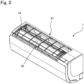
- Fig. 2 is a perspective view of the indoor unit 1 as viewed obliquely from above.
- Fig. 3 is a front view of the indoor unit 1.
- the indoor unit 1 includes a casing 21, and the indoor heat exchanger 15 (illustrated in Fig. 1 ), the indoor fan 18 (illustrated in Fig. 1 ), and the like are accommodated in the casing 21.
- An upper portion of the casing 21 is provided with an intake port 22 through which indoor air is taken in.
- indoor air enters the casing 21 through the intake port 22 and flows toward the indoor fan 18 (cross-flow fan).
- a filter (not illustrated) is attached to the intake port 22.
- a lower portion of the casing 21 is provided with a blow-out port 23 through which air from the indoor fan 18 (indoor air subjected to heat exchange with the indoor heat exchanger 15) blows out.
- a horizontal flap 24 is rotatably attached to a peripheral edge portion of the blow-out port 23.
- the horizontal flap 24 changes its position from a stop position to close the blow-out port 23 to an operation position to open the blow-out port 23 to adjust a vertical airflow direction of air blown out from the blow-out port 23.
- Fig. 4 is a front view of the indoor heat exchanger 15.
- the indoor heat exchanger 15 includes a heat exchanger body 20, the heat exchanger body 20 including a heat exchange portion 201 and a plurality of heat transfer tubes 202 extending through the heat exchange portion 201 in a left-right direction.
- the heat exchange portion 201 and the heat transfer tubes 202 are each formed of aluminum or an aluminum alloy.
- the indoor heat exchanger 15 further includes a liquid-refrigerant connection pipe 31 and a gas-refrigerant connection pipe 32.
- the liquid-refrigerant connection pipe 31 and the gas-refrigerant connection pipe 32 are fluidly connected to the heat transfer tubes 202 of the heat exchanger body 20.
- the liquid-refrigerant connection pipe 31 is an example of a connection pipe, and constitutes a part of the connection pipe L1 (illustrated in Fig. 1 ).
- the gas-refrigerant connection pipe 32 is an example of the connection pipe, and constitutes a part of the connection pipe L2 (illustrated in Fig. 1 ).
- the liquid-refrigerant connection pipe 31 guides a liquid refrigerant from the electric expansion valve 14 to the heat exchanger body 20 during the cooling operation and the dehumidifying operation.
- the gas-refrigerant connection pipe 32 guides a gas refrigerant from the heat exchanger body 20 to the compressor 11 during the cooling operation and the dehumidifying operation.
- the liquid-refrigerant connection pipe 31 has includes a first liquid-refrigerant pipe 311 formed of aluminum or an aluminum alloy, and a second liquid-refrigerant pipe 312 formed of copper or a copper alloy.
- the first liquid-refrigerant pipe 311 has one end fluidly connected to a flow divider 33.
- the second liquid-refrigerant pipe 312 has one end fluidly connected to the other end of the first liquid-refrigerant pipe 311 through a third liquid-refrigerant pipe 313 formed of stainless steel.
- the second liquid-refrigerant pipe 312 has the other end fixed to a liquid-refrigerant flare union 41 by brazing.
- the third liquid-refrigerant pipe 313 has one end and the other end that is larger in outer diameter than the one end.
- the third liquid-refrigerant pipe 313 has the one end connected to the first liquid-refrigerant pipe 311.
- the third liquid-refrigerant pipe 313 has the other end connected to the second liquid-refrigerant pipe 312.
- the gas-refrigerant connection pipe 32 is similar in configuration to the liquid-refrigerant connection pipe 31, and includes a first gas-refrigerant pipe 321 formed of aluminum or an aluminum alloy, and a second gas-refrigerant pipe 322 formed of copper or a copper alloy.
- the first gas-refrigerant pipe 321 has one end fluidly connected to a flow divider (not illustrated).
- the second gas-refrigerant pipe 322 has one end fluidly connected to the other end of the first gas-refrigerant pipe 321 through a third gas-refrigerant pipe 323 formed of stainless steel.
- the second gas-refrigerant pipe 322 has the other end fixed to a gas-refrigerant flare union 42 by brazing.
- Fig. 5 is a front view of a main portion of the indoor heat exchanger 15.
- Fig. 6 is a top view of the main portion of the indoor heat exchanger 15.
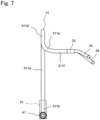
- Fig. 7 is a left-side view of the main portion of the indoor heat exchanger 15.
- the first liquid-refrigerant pipe 311 of the liquid-refrigerant connection pipe 31 includes a first section 311a extending along a vertical direction or a direction inclined relative to the vertical direction.
- the first liquid-refrigerant pipe 311 includes a second section 311b closer to the second liquid-refrigerant pipe 312 than the first section 311a.
- the second section 311b is continuous with a lower end (end adjacent to the second liquid-refrigerant pipe 312) of the first section 311a, and is bent from the lower end toward the second liquid-refrigerant pipe 312.
- the second section 311b is an example of a first curved portion.
- the first liquid-refrigerant pipe 311 includes a third section 311c closer to the second liquid-refrigerant pipe 312 than the second section 311b.
- the third section 311c is continuous with an end of the second section 311b adjacent to the second liquid-refrigerant pipe 312, and extends in a horizontal direction or a direction inclined relative to the horizontal direction.
- the first liquid-refrigerant pipe 311 has an outer peripheral surface extending from an end of the third section 311c adjacent to the second liquid-refrigerant pipe 312 to an end of the second section 311b adjacent to the first section 311a, the outer peripheral surface entirely covered with a waterproof tube 51.
- the waterproof tube 51 further covers an outer peripheral surface of the end of the third liquid-refrigerant pipe 313 adjacent to the first liquid-refrigerant pipe 311.
- the waterproof tube 51 is formed of a tube made of a waterproof material (for example, vinyl chloride, silicone rubber, fluorine-based polymer, or the like) and shrunk by heating.
- the first liquid-refrigerant pipe 311 includes a fourth section 311d closer to the heat exchanger body 20 than the first section 311a.
- the fourth section 311d is continuous with an upper end (heat-exchanger-body 20-side end) of the first section 311a, and the fourth section 311d extends upward from the end and then extends downward like a U-turn.
- the fourth section 311d is an example of a second curved portion.
- the first liquid-refrigerant pipe 311 includes a fifth section 311e closer to the heat exchanger body 20 than the fourth section 311d.
- the fifth section 311e is continuous with a lower end (heat-exchanger-body 20-side end) of the fourth section 311d, and is bent from the lower end toward the flow divider 33.
- the flow divider 33 is an example of a connection portion.
- the first liquid-refrigerant pipe 311 includes a sixth section 311f closer to the heat exchanger body 20 than the fifth section 311e.
- the sixth section 311f extends from a heat-exchanger-body 20-side end of the fifth section 311e to the flow divider 33.
- the flow divider 33 is formed of aluminum or an aluminum alloy.
- a branch pipe 34 formed of aluminum or an aluminum alloy is fixed to an end of the flow divider 33 adjacent to the heat exchanger body 20 by brazing.
- the gas-refrigerant connection pipe 32 is similar in configuration to the liquid-refrigerant connection pipe 31.
- the elongation of the second section 311b (first curved portion) of the liquid-refrigerant connection pipe 31 connected to the heat exchanger body 20 through the flow divider 33 (connection portion) is made greater than or equal to 30%, and the elongation of the first curved portion of the gas-refrigerant connection pipe 32 is made greater than or equal to 30%.
- the liquid-refrigerant connection pipe 31 includes the fourth section 311d (second curved portion) between the flow divider 33 and the second section 311b, when bending stress acts on the second section 311b, the bending stress is partially received by the fourth section 311d, so that it is possible to prevent stress concentration on the second section 311b and reduce the risk of breakage of the second section 311b (the same applies to the gas-refrigerant connection pipe 32).
- the indoor heat exchanger 15 provids with the liquid-refrigerant connection pipe 31 and the gas-refrigerant connection pipe 32.
- the liquid-refrigerant connection pipe 31 and the gas-refrigerant connection pipe 32 includes portions formed of aluminum or aluminum alloy that are lower in tensile strength than portions formed of copper, but is particularly effective in increasing work efficiency.
- the elongation of the second section 311b of the liquid-refrigerant connection pipe 31 may be greater than or equal to 40% (the same applies to the gas-refrigerant connection pipe 32). This allows the liquid-refrigerant connection pipe 31 and the gas-refrigerant connection pipe 32 to easily bend during installation of the indoor unit accommodating the heat exchanger body 20, thereby allowing a further increase in work efficiency during installation.
- the liquid-refrigerant connection pipe 31 and the gas-refrigerant connection pipe 32 each have an outer diameter as small as 9.52 mm ( ⁇ 3/8 inches) or less, thereby making the work of bending the liquid-refrigerant connection pipe 31 and the gas-refrigerant connection pipe 32 easier.
- the indoor unit 1 including the indoor heat exchanger 15 and the air conditioner including the indoor unit 1 allow the liquid-refrigerant connection pipe 31 and the gas-refrigerant connection pipe 32 to easily bend during installation of the indoor unit 1, thereby increasing work efficiency during installation.
- Fig. 8 is a flowchart for describing a method for manufacturing the indoor heat exchanger 15.
- a bending step S1 As illustrated in Fig. 8 , a bending step S1, an assembling step S2, and an annealing step S3 are included.
- the first liquid-refrigerant pipe 311 is bent into a predetermined shape to have the second section 311b (first curved portion) and the fourth section 311d (second curved portion) (bending step S1).
- the first liquid-refrigerant pipe 311 thus bent, the second liquid-refrigerant pipe 312, the third liquid-refrigerant pipe 313, and the liquid-refrigerant flare union 41 are assembled into the liquid-refrigerant connection pipe 31, and the liquid-refrigerant connection pipe 31, the flow divider 33 (connection portion), and the branch pipe 34 are assembled into a connection pipe assembly (assembling step S2).
- connection pipe assembly is brazed together and subjected to annealing treatment by in-furnace brazing (annealing step S3).
- an end (side remote from the flow divider 33) of the branch pipe 34 of the connection pipe assembly subjected to the annealing treatment is brazed to the heat exchanger body 20.
- the gas-refrigerant connection pipe 32 is also subjected to the bending step S1, the assembling step S2, and the annealing step S3 in a similar manner to complete the indoor heat exchanger 15.
- the second section 311b (first curved portion) of the first liquid-refrigerant connection pipe 311 and the first curved portion of the first gas-refrigerant connection pipe 321 are reduced in elongation by half due to work hardening (the same applies to the gas-refrigerant connection pipe 32).
- the annealing treatment in the annealing step S3 after the bending step S1 makes the second section 311b of the first liquid-refrigerant connection pipe 311 connected to the heat exchanger body 20 through the flow divider 33 and the first curved portion of the first gas-refrigerant connection pipe 321 larger in elongation than before the annealing step, the annealing treatment allowing the liquid-refrigerant connection pipe 31 and the gas-refrigerant connection pipe 32 to easily bend during installation of the indoor unit 1 accommodating the heat exchanger body 20, thereby increasing work efficiency during installation.
- performing the annealing treatment by in-furnace brazing allows each portion to be subjected to the brazing and the annealing treatment at the same time, and it is therefore possible to efficiently perform the brazing and the annealing treatment.
- one indoor unit 1 is connected to one outdoor unit 2, or alternatively, a plurality of indoor units 1 may be connected.
- the above-described air conditioner is of a pair-type, or alternatively, the air conditioner may be of a multi-type.
- the first liquid-refrigerant pipe 311 and the first gas-refrigerant pipe 321 are formed of aluminum or an aluminum alloy in the first embodiment, or alternatively, may be formed of metal other than aluminum and an aluminum alloy.
- the second liquid-refrigerant pipe 312 and the second gas-refrigerant pipe 322 are formed of copper or a copper alloy in the first embodiment, or alternatively, may be formed of metal other than copper or a copper alloy.
- the flow divider 33 and the branch pipe 34 are interposed between the heat transfer tubes 202 of the heat exchanger body 20 and the one end of the first liquid-refrigerant pipe 311 in the liquid-refrigerant connection pipe 31 in the first embodiment, or alternatively, the one end of the first liquid-refrigerant pipe 311 may be directly connected to the heat transfer tubes 202 of the heat exchanger body 20 with neither the flow divider 33 nor the branch pipe 34 interposed (the same applies to the gas-refrigerant connection pipe 32).
- the flow divider 33 that divides one refrigerant flow into two refrigerant flows is used in the first embodiment, or alternatively, a flow divider that divides one refrigerant flow into three or more refrigerant flows may be used.
- Fig. 9 is a front view of a liquid-refrigerant connection pipe 31 of an indoor heat exchanger 1015 of a second embodiment of the present disclosure and a peripheral portion of the liquid-refrigerant connection pipe 31.
- the indoor heat exchanger 1015 of the second embodiment is similar in configuration to the indoor heat exchanger 15 of the first embodiment except that a tubular member 61 covering the waterproof tube 51 is provided.
- the tubular member 61 illustrated in Fig. 9 is formed of a heat insulating material (for example, foamed polyester).
- the tubular member 61 covers the first liquid-refrigerant pipe 311 from the upper end of the first section 311a to a tip of the liquid refrigerant union 41.
- the tubular member 61 has an inner diameter set larger than a sum of an outer diameter of the liquid-refrigerant connection pipe 31 and an outer diameter of the gas-refrigerant connection pipe 32.
Landscapes
- Engineering & Computer Science (AREA)
- Mechanical Engineering (AREA)
- General Engineering & Computer Science (AREA)
- Physics & Mathematics (AREA)
- Thermal Sciences (AREA)
- Chemical & Material Sciences (AREA)
- Combustion & Propulsion (AREA)
- Air Filters, Heat-Exchange Apparatuses, And Housings Of Air-Conditioning Units (AREA)
- Details Of Heat-Exchange And Heat-Transfer (AREA)
Abstract
Description
- The present disclosure relates to an indoor heat exchanger, an indoor unit, an air conditioner, and a method for manufacturing an indoor heat exchanger.
- Examples of a known indoor heat exchanger include an indoor heat exchanger in which a connection pipe formed of copper has one end connected to a heat exchanger body and the other end connected to a flare nut (see, for example,
JP 2013-155892 A - Patent Literature 1:
JP 2013-155892 A - The indoor heat exchanger tends to suffer a decrease in work efficiency or breakage because bending process during manufacturing causes a curved portion to suffer work hardening to reduce in elongation, which makes the connection pipe less bending during installation of the indoor unit including the indoor heat exchanger.
- The present disclosure proposes an indoor heat exchanger that allows a connection pipe to easily bend during installation.
- The present disclosure further proposes an indoor unit including the indoor heat exchanger and an air conditioner including the indoor unit.
- The present disclosure further proposes a method for manufacturing an indoor heat exchanger that allows a connection pipe to easily bend during installation.
- An indoor heat exchanger of the present disclosure includes:
- a heat exchanger body; and
- a connection pipe connected to the heat exchanger body through a connection portion,
- in which
- the connection pipe includes a first curved portion with an elongation of 30% or greater.
- Here, the elongation is measured in accordance with JIS Z2201 and Z2241 and is a ratio, expressed in percentage, between elongation occurring between gauge marks on a test specimen before the test specimen breaks and a gauge length in a tensile test.
- According to the present disclosure, the connection pipe can be easily bent during installation of an indoor unit accommodating the heat exchanger body, thereby increasing work efficiency during installation.
- In the indoor heat exchanger according to one aspect of the present disclosure, the connection pipe includes a second curved portion between the connection portion and the first curved portion.
- According to the present disclosure, when bending stress acts on the first curved portion, the bending stress is partially received by the second curved portion, so that it is possible to prevent stress concentration on the first curved portion and reduce the risk of breakage of the first curved portion.
- In the indoor heat exchanger according to one aspect of the present disclosure, the second curved portion has an elongation of 20% or less.
- According to the present disclosure, it is possible to reduce a stress load applied to the heat exchanger body when bending stress acts on the first curved portion.
- The indoor heat exchanger according to one aspect of the present disclosure further includes a tubular member covering the first curved portion.
- According to the present disclosure, the tubular member can reduce bending stress applied to the first curved portion.
- In the indoor heat exchanger according to one aspect of the present disclosure, the connection pipe is a pipe formed of aluminum or an aluminum alloy.
- According to the present disclosure, the connection pipe formed of aluminum or aluminum alloy that is lower in tensile strength than a connection pipe formed of copper is particularly effective in increasing work efficiency.
- In the indoor heat exchanger according to one aspect of the present disclosure, the first curved portion has an elongation of 40% or greater.
- According to the present disclosure, the connection pipe can be bent more easily during installation of the indoor unit accommodating the heat exchanger body, thereby allowing a further increase in work efficiency during installation.
- In the indoor heat exchanger according to one aspect of the present disclosure, the connection pipe has an outer diameter of 9.52 mm or less.
- According to the present disclosure, since the outer diameter of the connection pipe is as small as 9.52 mm (≈ 3/8 inches) or less, the connection pipe can be bent more easily.
- An indoor unit according to one aspect of the present disclosure includes any of the indoor heat exchangers.
- According to the present disclosure, the connection pipe can be easily bent during installation of the indoor unit accommodating the indoor heat exchanger, thereby increasing work efficiency during installation.
- An air conditioner according to one aspect of the present disclosure includes the indoor unit.
- According to the present disclosure, the connection pipe can be easily bent during installation of the indoor unit, thereby increasing work efficiency during installation.
- A method for manufacturing an indoor heat exchanger according to one aspect of the present disclosure is a method for manufacturing an indoor heat exchanger including a heat exchanger body and a connection pipe connected to the heat exchanger body through a connection portion, the method including:
- a bending step of bending the connection pipe to form a first curved portion in the connection pipe; and
- an annealing step of performing annealing treatment on the first curved portion after the bending step to make the first curved portion larger in elongation than before the annealing treatment.
- According to the present disclosure, the annealing step after the bending step makes the first curved portion of the connection pipe connected to the heat exchanger body through the connection portion larger in elongation than before the annealing treatment. The annealing step allows the connection pipe to easily bend during installation of the indoor unit accommodating the heat exchanger body, thereby increasing work efficiency during installation.
- In the method for manufacturing an indoor heat exchanger according to one aspect of the present disclosure, the annealing treatment is performed by in-furnace brazing in the annealing step.
- According to the present disclosure, performing the annealing treatment by in-furnace brazing allows each portion to be subjected to the brazing and the annealing treatment at the same time, and it is therefore possible to efficiently perform the brazing and the annealing treatment.
-
-
Fig. 1 is a refrigerant circuit diagram of an air conditioner of a first embodiment of the present disclosure. -
Fig. 2 is a perspective view of an indoor unit of the air conditioner of the first embodiment. -
Fig. 3 is a front view of the indoor unit of the air conditioner of the first embodiment. -
Fig. 4 is a front view of an indoor heat exchanger of the first embodiment and a peripheral portion of the indoor heat exchanger. -
Fig. 5 is a front view of a main portion of the indoor heat exchanger of the first embodiment. -
Fig. 6 is a top view of the main portion of the indoor heat exchanger of the first embodiment. -
Fig. 7 is a left-side view of the main portion of the indoor heat exchanger of the first embodiment. -
Fig. 8 is a flowchart for describing a method for manufacturing the indoor heat exchanger of the first embodiment. -
Fig. 9 is a front view of an indoor heat exchanger of a second embodiment of the present disclosure and a peripheral portion of the indoor heat exchanger. - An indoor unit including an indoor heat exchanger and an air conditioner of the present disclosure will be described in detail below with reference to embodiments illustrated in the drawings. Note that the same parts in the drawings are denoted by the same reference numerals to avoid the description from being redundant. Upper, lower, left, and right in the description correspond to upper, lower, left, and right in a state where an indoor unit is installed in a room.
-
Fig. 1 is a diagram illustrating a refrigerant circuit RC provided in an air conditioner of a first embodiment of the present disclosure. The air conditioner of the first embodiment includes theindoor unit 1 and anoutdoor unit 2 connected to theindoor unit 1 via the refrigerant circuit RC. The air conditioner is of a type in which theoutdoor unit 2 is paired one-to-one with theindoor unit 1. - The refrigerant circuit RC includes a
compressor 11, a four-way switching valve 12, an outdoor heat exchanger 13, anelectric expansion valve 14, anindoor heat exchanger 15, and anaccumulator 16. As thecompressor 11 is driven, a refrigerant (for example, an HFC refrigerant such as R410A or R32) circulates in the refrigerant circuit RC. - More specifically, the four-
way switching valve 12 has one end connected to a discharge side of thecompressor 11. The four-way switching valve 12 has the other end connected to one end of the outdoor heat exchanger 13. The outdoor heat exchanger 13 has the other end connected to one end of theelectric expansion valve 14. Theelectric expansion valve 14 has the other end connected to one end of theindoor heat exchanger 15 via a shutoff valve V1 and a connection pipe L1. Theindoor heat exchanger 15 has the other end connected to one end of theaccumulator 16 via a connection pipe L2, a shutoff valve V2, and the four-way switching valve 12. Theaccumulator 16 has the other end connected to an intake-side portion of thecompressor 11. - The
indoor unit 1 is equipped with theindoor heat exchanger 15 and anindoor fan 18. Theindoor fan 18 is, for example, a cross-flow fan, and takes in indoor air through theindoor heat exchanger 15. - The
outdoor unit 2 is equipped with thecompressor 11, the four-way switching valve 12, the outdoor heat exchanger 13, theelectric expansion valve 14, theaccumulator 16, and anoutdoor fan 17. - The air conditioner switches the four-
way switching valve 12 to a switching position indicated by a solid line to activate thecompressor 11 for cooling operation and dehumidifying operation, and switches the four-way switching valve 12 to a switching position indicated by a dotted line to activate thecompressor 11 for heating operation. A direction of a solid arrow inFig. 1 indicates a direction in which the refrigerant flows during the cooling operation and the dehumidifying operation. A direction indicated by a dotted arrow inFig. 1 indicates a direction in which the refrigerant flows during the heating operation. -
Fig. 2 is a perspective view of theindoor unit 1 as viewed obliquely from above.Fig. 3 is a front view of theindoor unit 1. - As illustrated in
Figs. 2 and3 , theindoor unit 1 includes acasing 21, and the indoor heat exchanger 15 (illustrated inFig. 1 ), the indoor fan 18 (illustrated inFig. 1 ), and the like are accommodated in thecasing 21. - An upper portion of the
casing 21 is provided with anintake port 22 through which indoor air is taken in. When theindoor fan 18 is driven, indoor air enters thecasing 21 through theintake port 22 and flows toward the indoor fan 18 (cross-flow fan). At this time, in order to prevent dust and the like from entering thecasing 21 together with indoor air, a filter (not illustrated) is attached to theintake port 22. - A lower portion of the
casing 21 is provided with a blow-outport 23 through which air from the indoor fan 18 (indoor air subjected to heat exchange with the indoor heat exchanger 15) blows out. Ahorizontal flap 24 is rotatably attached to a peripheral edge portion of the blow-outport 23. - When the cooling operation or the like is started, the
horizontal flap 24 changes its position from a stop position to close the blow-outport 23 to an operation position to open the blow-outport 23 to adjust a vertical airflow direction of air blown out from the blow-outport 23. -
Fig. 4 is a front view of theindoor heat exchanger 15. - The
indoor heat exchanger 15 includes aheat exchanger body 20, theheat exchanger body 20 including aheat exchange portion 201 and a plurality ofheat transfer tubes 202 extending through theheat exchange portion 201 in a left-right direction. Theheat exchange portion 201 and theheat transfer tubes 202 are each formed of aluminum or an aluminum alloy. - The
indoor heat exchanger 15 further includes a liquid-refrigerant connection pipe 31 and a gas-refrigerant connection pipe 32. The liquid-refrigerant connection pipe 31 and the gas-refrigerant connection pipe 32 are fluidly connected to theheat transfer tubes 202 of theheat exchanger body 20. The liquid-refrigerant connection pipe 31 is an example of a connection pipe, and constitutes a part of the connection pipe L1 (illustrated inFig. 1 ). The gas-refrigerant connection pipe 32 is an example of the connection pipe, and constitutes a part of the connection pipe L2 (illustrated inFig. 1 ). The liquid-refrigerant connection pipe 31 guides a liquid refrigerant from theelectric expansion valve 14 to theheat exchanger body 20 during the cooling operation and the dehumidifying operation. On the other hand, the gas-refrigerant connection pipe 32 guides a gas refrigerant from theheat exchanger body 20 to thecompressor 11 during the cooling operation and the dehumidifying operation. - The liquid-
refrigerant connection pipe 31 has includes a first liquid-refrigerant pipe 311 formed of aluminum or an aluminum alloy, and a second liquid-refrigerant pipe 312 formed of copper or a copper alloy. The first liquid-refrigerant pipe 311 has one end fluidly connected to aflow divider 33. - The second liquid-
refrigerant pipe 312 has one end fluidly connected to the other end of the first liquid-refrigerant pipe 311 through a third liquid-refrigerant pipe 313 formed of stainless steel. On the other hand, the second liquid-refrigerant pipe 312 has the other end fixed to a liquid-refrigerant flare union 41 by brazing. - The third liquid-
refrigerant pipe 313 has one end and the other end that is larger in outer diameter than the one end. The third liquid-refrigerant pipe 313 has the one end connected to the first liquid-refrigerant pipe 311. On the other hand, the third liquid-refrigerant pipe 313 has the other end connected to the second liquid-refrigerant pipe 312. - The gas-
refrigerant connection pipe 32 is similar in configuration to the liquid-refrigerant connection pipe 31, and includes a first gas-refrigerant pipe 321 formed of aluminum or an aluminum alloy, and a second gas-refrigerant pipe 322 formed of copper or a copper alloy. - The first gas-
refrigerant pipe 321 has one end fluidly connected to a flow divider (not illustrated). - The second gas-
refrigerant pipe 322 has one end fluidly connected to the other end of the first gas-refrigerant pipe 321 through a third gas-refrigerant pipe 323 formed of stainless steel. On the other hand, the second gas-refrigerant pipe 322 has the other end fixed to a gas-refrigerant flare union 42 by brazing. -
Fig. 5 is a front view of a main portion of theindoor heat exchanger 15.Fig. 6 is a top view of the main portion of theindoor heat exchanger 15.Fig. 7 is a left-side view of the main portion of theindoor heat exchanger 15. - As illustrated in
Figs. 5 to 7 , the first liquid-refrigerant pipe 311 of the liquid-refrigerant connection pipe 31 includes afirst section 311a extending along a vertical direction or a direction inclined relative to the vertical direction. The first liquid-refrigerant pipe 311 includes asecond section 311b closer to the second liquid-refrigerant pipe 312 than thefirst section 311a. Thesecond section 311b is continuous with a lower end (end adjacent to the second liquid-refrigerant pipe 312) of thefirst section 311a, and is bent from the lower end toward the second liquid-refrigerant pipe 312. Thesecond section 311b is an example of a first curved portion. - The first liquid-
refrigerant pipe 311 includes athird section 311c closer to the second liquid-refrigerant pipe 312 than thesecond section 311b. Thethird section 311c is continuous with an end of thesecond section 311b adjacent to the second liquid-refrigerant pipe 312, and extends in a horizontal direction or a direction inclined relative to the horizontal direction. - The first liquid-
refrigerant pipe 311 has an outer peripheral surface extending from an end of thethird section 311c adjacent to the second liquid-refrigerant pipe 312 to an end of thesecond section 311b adjacent to thefirst section 311a, the outer peripheral surface entirely covered with awaterproof tube 51. Thewaterproof tube 51 further covers an outer peripheral surface of the end of the third liquid-refrigerant pipe 313 adjacent to the first liquid-refrigerant pipe 311. Thewaterproof tube 51 is formed of a tube made of a waterproof material (for example, vinyl chloride, silicone rubber, fluorine-based polymer, or the like) and shrunk by heating. - The first liquid-
refrigerant pipe 311 includes afourth section 311d closer to theheat exchanger body 20 than thefirst section 311a. Thefourth section 311d is continuous with an upper end (heat-exchanger-body 20-side end) of thefirst section 311a, and thefourth section 311d extends upward from the end and then extends downward like a U-turn. Thefourth section 311d is an example of a second curved portion. - The first liquid-
refrigerant pipe 311 includes afifth section 311e closer to theheat exchanger body 20 than thefourth section 311d. Thefifth section 311e is continuous with a lower end (heat-exchanger-body 20-side end) of thefourth section 311d, and is bent from the lower end toward theflow divider 33. Theflow divider 33 is an example of a connection portion. - The first liquid-
refrigerant pipe 311 includes asixth section 311f closer to theheat exchanger body 20 than thefifth section 311e. Thesixth section 311f extends from a heat-exchanger-body 20-side end of thefifth section 311e to theflow divider 33. - The
flow divider 33 is formed of aluminum or an aluminum alloy. Abranch pipe 34 formed of aluminum or an aluminum alloy is fixed to an end of theflow divider 33 adjacent to theheat exchanger body 20 by brazing. - In the first embodiment, the gas-
refrigerant connection pipe 32 is similar in configuration to the liquid-refrigerant connection pipe 31. - In the
indoor heat exchanger 15 configured as described above, the elongation of thesecond section 311b (first curved portion) of the liquid-refrigerant connection pipe 31 connected to theheat exchanger body 20 through the flow divider 33 (connection portion) is made greater than or equal to 30%, and the elongation of the first curved portion of the gas-refrigerant connection pipe 32 is made greater than or equal to 30%. This allows the liquid-refrigerant connection pipe 31 and the gas-refrigerant connection pipe 32 to easily bend during installation of the indoor unit accommodating theheat exchanger body 20, thereby increasing work efficiency during installation. - Since the liquid-
refrigerant connection pipe 31 includes thefourth section 311d (second curved portion) between theflow divider 33 and thesecond section 311b, when bending stress acts on thesecond section 311b, the bending stress is partially received by thefourth section 311d, so that it is possible to prevent stress concentration on thesecond section 311b and reduce the risk of breakage of thesecond section 311b (the same applies to the gas-refrigerant connection pipe 32). - It is possible to reduce, by making the elongation of the
fourth section 311d of the liquid-refrigerant connection pipe 31 less than or equal to 20%, a stress load applied to theheat exchanger body 20 when bending stress acts on thesecond section 311b (first curved portion) (the same applies to the gas-refrigerant connection pipe 32). - The
indoor heat exchanger 15 provids with the liquid-refrigerant connection pipe 31 and the gas-refrigerant connection pipe 32. The liquid-refrigerant connection pipe 31 and the gas-refrigerant connection pipe 32 includes portions formed of aluminum or aluminum alloy that are lower in tensile strength than portions formed of copper, but is particularly effective in increasing work efficiency. - Alternatively, the elongation of the
second section 311b of the liquid-refrigerant connection pipe 31 may be greater than or equal to 40% (the same applies to the gas-refrigerant connection pipe 32). This allows the liquid-refrigerant connection pipe 31 and the gas-refrigerant connection pipe 32 to easily bend during installation of the indoor unit accommodating theheat exchanger body 20, thereby allowing a further increase in work efficiency during installation. - The liquid-
refrigerant connection pipe 31 and the gas-refrigerant connection pipe 32 each have an outer diameter as small as 9.52 mm (≈ 3/8 inches) or less, thereby making the work of bending the liquid-refrigerant connection pipe 31 and the gas-refrigerant connection pipe 32 easier. - The
indoor unit 1 including theindoor heat exchanger 15 and the air conditioner including theindoor unit 1 allow the liquid-refrigerant connection pipe 31 and the gas-refrigerant connection pipe 32 to easily bend during installation of theindoor unit 1, thereby increasing work efficiency during installation. -
Fig. 8 is a flowchart for describing a method for manufacturing theindoor heat exchanger 15. - As illustrated in
Fig. 8 , a bending step S1, an assembling step S2, and an annealing step S3 are included. - Specifically, the first liquid-
refrigerant pipe 311 is bent into a predetermined shape to have thesecond section 311b (first curved portion) and thefourth section 311d (second curved portion) (bending step S1). - Next, the first liquid-
refrigerant pipe 311 thus bent, the second liquid-refrigerant pipe 312, the third liquid-refrigerant pipe 313, and the liquid-refrigerant flare union 41 are assembled into the liquid-refrigerant connection pipe 31, and the liquid-refrigerant connection pipe 31, the flow divider 33 (connection portion), and thebranch pipe 34 are assembled into a connection pipe assembly (assembling step S2). - Then, the portions of the connection pipe assembly are brazed together and subjected to annealing treatment by in-furnace brazing (annealing step S3).
- As described above, an end (side remote from the flow divider 33) of the
branch pipe 34 of the connection pipe assembly subjected to the annealing treatment is brazed to theheat exchanger body 20. - The gas-
refrigerant connection pipe 32 is also subjected to the bending step S1, the assembling step S2, and the annealing step S3 in a similar manner to complete theindoor heat exchanger 15. - According to the method for manufacturing the
indoor heat exchanger 15, in the bending step S1, thesecond section 311b (first curved portion) of the first liquid-refrigerant connection pipe 311 and the first curved portion of the first gas-refrigerant connection pipe 321 are reduced in elongation by half due to work hardening (the same applies to the gas-refrigerant connection pipe 32). The annealing treatment in the annealing step S3 after the bending step S1 makes thesecond section 311b of the first liquid-refrigerant connection pipe 311 connected to theheat exchanger body 20 through theflow divider 33 and the first curved portion of the first gas-refrigerant connection pipe 321 larger in elongation than before the annealing step, the annealing treatment allowing the liquid-refrigerant connection pipe 31 and the gas-refrigerant connection pipe 32 to easily bend during installation of theindoor unit 1 accommodating theheat exchanger body 20, thereby increasing work efficiency during installation. - In the annealing step S3, performing the annealing treatment by in-furnace brazing allows each portion to be subjected to the brazing and the annealing treatment at the same time, and it is therefore possible to efficiently perform the brazing and the annealing treatment.
- In the air conditioner of the first embodiment, one
indoor unit 1 is connected to oneoutdoor unit 2, or alternatively, a plurality ofindoor units 1 may be connected. In other words, the above-described air conditioner is of a pair-type, or alternatively, the air conditioner may be of a multi-type. - The first liquid-
refrigerant pipe 311 and the first gas-refrigerant pipe 321 are formed of aluminum or an aluminum alloy in the first embodiment, or alternatively, may be formed of metal other than aluminum and an aluminum alloy. - The second liquid-
refrigerant pipe 312 and the second gas-refrigerant pipe 322 are formed of copper or a copper alloy in the first embodiment, or alternatively, may be formed of metal other than copper or a copper alloy. - The
flow divider 33 and thebranch pipe 34 are interposed between theheat transfer tubes 202 of theheat exchanger body 20 and the one end of the first liquid-refrigerant pipe 311 in the liquid-refrigerant connection pipe 31 in the first embodiment, or alternatively, the one end of the first liquid-refrigerant pipe 311 may be directly connected to theheat transfer tubes 202 of theheat exchanger body 20 with neither theflow divider 33 nor thebranch pipe 34 interposed (the same applies to the gas-refrigerant connection pipe 32). - The
flow divider 33 that divides one refrigerant flow into two refrigerant flows is used in the first embodiment, or alternatively, a flow divider that divides one refrigerant flow into three or more refrigerant flows may be used. -
Fig. 9 is a front view of a liquid-refrigerant connection pipe 31 of anindoor heat exchanger 1015 of a second embodiment of the present disclosure and a peripheral portion of the liquid-refrigerant connection pipe 31. Theindoor heat exchanger 1015 of the second embodiment is similar in configuration to theindoor heat exchanger 15 of the first embodiment except that atubular member 61 covering thewaterproof tube 51 is provided. - The
tubular member 61 illustrated inFig. 9 is formed of a heat insulating material (for example, foamed polyester). Thetubular member 61 covers the first liquid-refrigerant pipe 311 from the upper end of thefirst section 311a to a tip of the liquidrefrigerant union 41. - Although not illustrated, most of the gas-
refrigerant connection pipe 32 is inserted into thetubular member 61 in a manner similar to the liquid-refrigerant connection pipe 31. Therefore, thetubular member 61 has an inner diameter set larger than a sum of an outer diameter of the liquid-refrigerant connection pipe 31 and an outer diameter of the gas-refrigerant connection pipe 32. - In the
indoor heat exchanger 1015 configured as described above, since thetubular member 61 covers thewaterproof tube 51, liquid such as dew condensation water is prevented from adhering to the covering member or thewaterproof tube 51. - Covering the
second section 311b of the first liquid-refrigerant connection pipe 311 with thetubular member 61 allows a reduction in bending stress applied to thesecond section 311b (the same applies to the gas-refrigerant connection pipe 32). - The foregoing description concerns specific embodiments of the present disclosure; however, the present disclosure is not limited to the first and second embodiments, and various modifications and variations may be made within the scope of the present disclosure.
-
- 1
- indoor unit
- 15, 1015
- indoor heat exchanger
- 20
- heat exchanger body
- 31
- liquid-refrigerant connection pipe (connection pipe)
- 32
- gas-refrigerant connection pipe (connection pipe)
- 33
- flow divider (connection portion)
- 34
- branch pipe
- 41
- liquid-refrigerant flare union
- 42
- gas-refrigerant flare union
- 51
- waterproof tube
- 61
- tubular member
- 201
- heat exchange portion
- 202
- heat transfer tube
- 311
- first liquid-refrigerant pipe
- 311a
- first section
- 311b
- second section (first curved portion)
- 311c
- third section
- 311d
- fourth section (second curved portion)
- 311e
- fifth section
- 311f
- sixth section
- 312
- second liquid-refrigerant pipe
- 313
- third liquid-refrigerant pipe
- 321
- first gas-refrigerant pipe
- 322
- second gas-refrigerant pipe
Claims (11)
- An indoor heat exchanger (15) comprising:a heat exchanger body (20); anda connection pipe (31, 32) connected to the heat exchanger body (20) through a connection portion (33),whereinthe connection pipe (31, 32) includes a first curved portion (311b) with an elongation of 30% or greater.
- The indoor heat exchanger (15) according to claim 1, wherein
the connection pipe (31, 32) includes a second curved portion (311d) between the connection portion (33) and the first curved portion (311b). - The indoor heat exchanger (15) according to claim 2, wherein
the second curved portion (311d) has an elongation of 20% or less. - The indoor heat exchanger (15) according to any one of claims 1 to 3, further comprising a tubular member (61) covering the first curved portion (311b).
- The indoor heat exchanger (15) according to any one of claims 1 to 4, wherein
the connection pipe (31, 32) is a pipe formed of aluminum or an aluminum alloy. - The indoor heat exchanger (15) according to any one of claims 1 to 5, wherein
the first curved portion (311b) has an elongation of 40% or greater. - The indoor heat exchanger (15) according to any one of claims 1 to 6, wherein
the connection pipe (31, 32) has an outer diameter of 9.52 mm or less. - An indoor unit (1) comprising an indoor heat exchanger (15) according to any one of claims 1 to 7.
- An air conditioner comprising an indoor unit (1) according to claim 8.
- A method for manufacturing an indoor heat exchanger (15) including a heat exchanger body (20) and a connection pipe (31, 32) connected to the heat exchanger body (20) through a connection portion (33), the method comprising:a bending step (S1) of bending the connection pipe (31, 32) to form a first curved portion (311b) in the connection pipe (31, 32); andan annealing step (S3) of performing annealing treatment on the first curved portion (311b) after the bending step (S1) to make the first curved portion (311b) larger in elongation than before the annealing treatment.
- The method for manufacturing an indoor heat exchanger according to claim 10, wherein
in the annealing step (S3), the annealing treatment is performed by in-furnace brazing.
Applications Claiming Priority (2)
| Application Number | Priority Date | Filing Date | Title |
|---|---|---|---|
| JP2021161764A JP7323819B2 (en) | 2021-09-30 | 2021-09-30 | Method for manufacturing indoor heat exchanger |
| PCT/JP2022/018451 WO2023053549A1 (en) | 2021-09-30 | 2022-04-21 | Indoor heat exchanger, indoor unit, air conditioner, and method for manufacturing indoor heat exchanger |
Publications (3)
| Publication Number | Publication Date |
|---|---|
| EP4407241A1 true EP4407241A1 (en) | 2024-07-31 |
| EP4407241A4 EP4407241A4 (en) | 2025-01-08 |
| EP4407241B1 EP4407241B1 (en) | 2026-05-20 |
Family
ID=85782219
Family Applications (1)
| Application Number | Title | Priority Date | Filing Date |
|---|---|---|---|
| EP22875432.1A Active EP4407241B1 (en) | 2021-09-30 | 2022-04-21 | Indoor heat exchanger, indoor unit, air conditioning system and method for manufacturing an indoor heat exchanger |
Country Status (5)
| Country | Link |
|---|---|
| US (1) | US20240240805A1 (en) |
| EP (1) | EP4407241B1 (en) |
| JP (2) | JP7323819B2 (en) |
| CN (1) | CN117616235A (en) |
| WO (1) | WO2023053549A1 (en) |
Family Cites Families (9)
| Publication number | Priority date | Publication date | Assignee | Title |
|---|---|---|---|---|
| JPH0570870A (en) * | 1991-09-13 | 1993-03-23 | Kobe Steel Ltd | Production of copper alloy for heat transfer pipe and heat transfer pipe for heat exchanger |
| JP3351331B2 (en) * | 1998-01-16 | 2002-11-25 | 住友金属工業株式会社 | A method of manufacturing a deformed metal tube and a method of manufacturing a bent metal tube. |
| JP4015047B2 (en) | 2002-04-02 | 2007-11-28 | 株式会社コベルコ マテリアル銅管 | Internal grooved heat transfer tube |
| JP5877336B2 (en) * | 2011-06-14 | 2016-03-08 | パナソニックIpマネジメント株式会社 | Air conditioner heat exchanger |
| JP5881435B2 (en) | 2012-01-27 | 2016-03-09 | 三菱電機株式会社 | Heat exchanger and air conditioner equipped with the same |
| JP6079619B2 (en) | 2013-12-27 | 2017-02-15 | ダイキン工業株式会社 | Air conditioning indoor unit |
| JP5999083B2 (en) * | 2013-12-27 | 2016-09-28 | ダイキン工業株式会社 | HEAT EXCHANGE DEVICE AND METHOD OF PRODUCING HEAT EXCHANGE DEVICE |
| JP5861723B2 (en) * | 2014-01-30 | 2016-02-16 | ダイキン工業株式会社 | Air conditioner indoor unit |
| JP6477649B2 (en) * | 2016-09-30 | 2019-03-06 | ダイキン工業株式会社 | Manufacturing method of heat exchanger |
-
2021
- 2021-09-30 JP JP2021161764A patent/JP7323819B2/en active Active
-
2022
- 2022-04-21 EP EP22875432.1A patent/EP4407241B1/en active Active
- 2022-04-21 WO PCT/JP2022/018451 patent/WO2023053549A1/en not_active Ceased
- 2022-04-21 CN CN202280048429.0A patent/CN117616235A/en active Pending
-
2023
- 2023-03-13 JP JP2023038747A patent/JP7773060B2/en active Active
-
2024
- 2024-03-29 US US18/622,148 patent/US20240240805A1/en active Pending
Also Published As
| Publication number | Publication date |
|---|---|
| JP7773060B2 (en) | 2025-11-19 |
| EP4407241B1 (en) | 2026-05-20 |
| EP4407241A4 (en) | 2025-01-08 |
| WO2023053549A1 (en) | 2023-04-06 |
| CN117616235A (en) | 2024-02-27 |
| US20240240805A1 (en) | 2024-07-18 |
| JP2023051217A (en) | 2023-04-11 |
| JP2023078267A (en) | 2023-06-06 |
| JP7323819B2 (en) | 2023-08-09 |
Similar Documents
| Publication | Publication Date | Title |
|---|---|---|
| EP2423609B1 (en) | Heat exchanger and air conditioner on which this heat exchanger is mounted | |
| AU2015212207B2 (en) | Air conditioner indoor unit | |
| EP4644804A2 (en) | Air conditioner | |
| US20240240802A1 (en) | Indoor unit and air conditioner | |
| US20240240805A1 (en) | Indoor heat exchanger, indoor unit, air conditioner, and method for manufacturing indoor heat exchanger | |
| US20240240803A1 (en) | Indoor unit and air conditioner | |
| US20180283703A1 (en) | Indoor unit for air conditioner | |
| US12104862B2 (en) | Heat exchanger and air-conditioning apparatus | |
| CN102022862A (en) | Air conditioner | |
| KR100803774B1 (en) | Installation piping of air conditioner | |
| US20240230112A1 (en) | Air conditioner indoor unit and air conditioner | |
| US12196433B2 (en) | Heat exchange unit and air conditioner | |
| JP7580182B1 (en) | Air conditioners | |
| JP7503719B1 (en) | Air conditioners | |
| JP7583287B2 (en) | Heat exchanger and air conditioner | |
| JP2023051213A (en) | Piping connection structure and air conditioner | |
| TR2025017692A2 (en) | FLUID LINE CONNECTION ELEMENT AND INSTALLATION KIT | |
| WO2025069924A1 (en) | Heat exchanger, air conditioner, and heat exchanger manufacturing method | |
| JP2025091957A (en) | Air conditioners |
Legal Events
| Date | Code | Title | Description |
|---|---|---|---|
| STAA | Information on the status of an ep patent application or granted ep patent |
Free format text: STATUS: THE INTERNATIONAL PUBLICATION HAS BEEN MADE |
|
| PUAI | Public reference made under article 153(3) epc to a published international application that has entered the european phase |
Free format text: ORIGINAL CODE: 0009012 |
|
| STAA | Information on the status of an ep patent application or granted ep patent |
Free format text: STATUS: REQUEST FOR EXAMINATION WAS MADE |
|
| 17P | Request for examination filed |
Effective date: 20240422 |
|
| AK | Designated contracting states |
Kind code of ref document: A1 Designated state(s): AL AT BE BG CH CY CZ DE DK EE ES FI FR GB GR HR HU IE IS IT LI LT LU LV MC MK MT NL NO PL PT RO RS SE SI SK SM TR |
|
| REG | Reference to a national code |
Ref country code: DE Ref legal event code: R079 Free format text: PREVIOUS MAIN CLASS: F24F0001006700 Ipc: F24F0001005900 Ref country code: DE Ref legal event code: R079 Ref document number: 602022037337 Country of ref document: DE Free format text: PREVIOUS MAIN CLASS: F24F0001006700 Ipc: F24F0001005900 |
|
| A4 | Supplementary search report drawn up and despatched |
Effective date: 20241210 |
|
| DAV | Request for validation of the european patent (deleted) | ||
| DAX | Request for extension of the european patent (deleted) | ||
| RIC1 | Information provided on ipc code assigned before grant |
Ipc: B23K 1/00 20060101ALI20241204BHEP Ipc: F28F 21/08 20060101ALI20241204BHEP Ipc: F28F 19/06 20060101ALI20241204BHEP Ipc: F28F 9/00 20060101ALI20241204BHEP Ipc: F24F 13/20 20060101ALI20241204BHEP Ipc: F24F 1/0068 20190101ALI20241204BHEP Ipc: F24F 1/0059 20190101AFI20241204BHEP |
|
| P01 | Opt-out of the competence of the unified patent court (upc) registered |
Free format text: CASE NUMBER: APP_1123/2025 Effective date: 20250108 |
|
| GRAP | Despatch of communication of intention to grant a patent |
Free format text: ORIGINAL CODE: EPIDOSNIGR1 |
|
| STAA | Information on the status of an ep patent application or granted ep patent |
Free format text: STATUS: GRANT OF PATENT IS INTENDED |
|
| INTG | Intention to grant announced |
Effective date: 20250912 |
|
| RIN1 | Information on inventor provided before grant (corrected) |
Inventor name: NAKANO, HIROYUKI |
|
| GRAJ | Information related to disapproval of communication of intention to grant by the applicant or resumption of examination proceedings by the epo deleted |
Free format text: ORIGINAL CODE: EPIDOSDIGR1 |
|
| STAA | Information on the status of an ep patent application or granted ep patent |
Free format text: STATUS: REQUEST FOR EXAMINATION WAS MADE |
|
| GRAP | Despatch of communication of intention to grant a patent |
Free format text: ORIGINAL CODE: EPIDOSNIGR1 |
|
| STAA | Information on the status of an ep patent application or granted ep patent |
Free format text: STATUS: GRANT OF PATENT IS INTENDED |
|
| INTC | Intention to grant announced (deleted) | ||
| INTG | Intention to grant announced |
Effective date: 20251216 |
|
| GRAJ | Information related to disapproval of communication of intention to grant by the applicant or resumption of examination proceedings by the epo deleted |
Free format text: ORIGINAL CODE: EPIDOSDIGR1 |
|
| STAA | Information on the status of an ep patent application or granted ep patent |
Free format text: STATUS: REQUEST FOR EXAMINATION WAS MADE |
|
| GRAP | Despatch of communication of intention to grant a patent |
Free format text: ORIGINAL CODE: EPIDOSNIGR1 |
|
| STAA | Information on the status of an ep patent application or granted ep patent |
Free format text: STATUS: GRANT OF PATENT IS INTENDED |
|
| INTC | Intention to grant announced (deleted) | ||
| INTG | Intention to grant announced |
Effective date: 20260206 |
|
| GRAS | Grant fee paid |
Free format text: ORIGINAL CODE: EPIDOSNIGR3 |
|
| GRAA | (expected) grant |
Free format text: ORIGINAL CODE: 0009210 |
|
| STAA | Information on the status of an ep patent application or granted ep patent |
Free format text: STATUS: THE PATENT HAS BEEN GRANTED |