EP4407206A1 - Improved method and apparatus for controlling a power-take-off assembly of a work vehicle - Google Patents
Improved method and apparatus for controlling a power-take-off assembly of a work vehicle Download PDFInfo
- Publication number
- EP4407206A1 EP4407206A1 EP24154276.0A EP24154276A EP4407206A1 EP 4407206 A1 EP4407206 A1 EP 4407206A1 EP 24154276 A EP24154276 A EP 24154276A EP 4407206 A1 EP4407206 A1 EP 4407206A1
- Authority
- EP
- European Patent Office
- Prior art keywords
- angular velocity
- take
- power
- assembly
- valve means
- Prior art date
- Legal status (The legal status is an assumption and is not a legal conclusion. Google has not performed a legal analysis and makes no representation as to the accuracy of the status listed.)
- Granted
Links
Images

Classifications
-
- F—MECHANICAL ENGINEERING; LIGHTING; HEATING; WEAPONS; BLASTING
- F16—ENGINEERING ELEMENTS AND UNITS; GENERAL MEASURES FOR PRODUCING AND MAINTAINING EFFECTIVE FUNCTIONING OF MACHINES OR INSTALLATIONS; THERMAL INSULATION IN GENERAL
- F16D—COUPLINGS FOR TRANSMITTING ROTATION; CLUTCHES; BRAKES
- F16D48/00—External control of clutches
-
- F—MECHANICAL ENGINEERING; LIGHTING; HEATING; WEAPONS; BLASTING
- F16—ENGINEERING ELEMENTS AND UNITS; GENERAL MEASURES FOR PRODUCING AND MAINTAINING EFFECTIVE FUNCTIONING OF MACHINES OR INSTALLATIONS; THERMAL INSULATION IN GENERAL
- F16D—COUPLINGS FOR TRANSMITTING ROTATION; CLUTCHES; BRAKES
- F16D2500/00—External control of clutches by electric or electronic means
- F16D2500/10—System to be controlled
- F16D2500/102—Actuator
- F16D2500/1026—Hydraulic
-
- F—MECHANICAL ENGINEERING; LIGHTING; HEATING; WEAPONS; BLASTING
- F16—ENGINEERING ELEMENTS AND UNITS; GENERAL MEASURES FOR PRODUCING AND MAINTAINING EFFECTIVE FUNCTIONING OF MACHINES OR INSTALLATIONS; THERMAL INSULATION IN GENERAL
- F16D—COUPLINGS FOR TRANSMITTING ROTATION; CLUTCHES; BRAKES
- F16D2500/00—External control of clutches by electric or electronic means
- F16D2500/10—System to be controlled
- F16D2500/104—Clutch
- F16D2500/10406—Clutch position
- F16D2500/10437—Power Take Off clutch
-
- F—MECHANICAL ENGINEERING; LIGHTING; HEATING; WEAPONS; BLASTING
- F16—ENGINEERING ELEMENTS AND UNITS; GENERAL MEASURES FOR PRODUCING AND MAINTAINING EFFECTIVE FUNCTIONING OF MACHINES OR INSTALLATIONS; THERMAL INSULATION IN GENERAL
- F16D—COUPLINGS FOR TRANSMITTING ROTATION; CLUTCHES; BRAKES
- F16D2500/00—External control of clutches by electric or electronic means
- F16D2500/30—Signal inputs
- F16D2500/304—Signal inputs from the clutch
- F16D2500/3041—Signal inputs from the clutch from the input shaft
- F16D2500/30415—Speed of the input shaft
-
- F—MECHANICAL ENGINEERING; LIGHTING; HEATING; WEAPONS; BLASTING
- F16—ENGINEERING ELEMENTS AND UNITS; GENERAL MEASURES FOR PRODUCING AND MAINTAINING EFFECTIVE FUNCTIONING OF MACHINES OR INSTALLATIONS; THERMAL INSULATION IN GENERAL
- F16D—COUPLINGS FOR TRANSMITTING ROTATION; CLUTCHES; BRAKES
- F16D2500/00—External control of clutches by electric or electronic means
- F16D2500/30—Signal inputs
- F16D2500/304—Signal inputs from the clutch
- F16D2500/3042—Signal inputs from the clutch from the output shaft
- F16D2500/30426—Speed of the output shaft
-
- F—MECHANICAL ENGINEERING; LIGHTING; HEATING; WEAPONS; BLASTING
- F16—ENGINEERING ELEMENTS AND UNITS; GENERAL MEASURES FOR PRODUCING AND MAINTAINING EFFECTIVE FUNCTIONING OF MACHINES OR INSTALLATIONS; THERMAL INSULATION IN GENERAL
- F16D—COUPLINGS FOR TRANSMITTING ROTATION; CLUTCHES; BRAKES
- F16D2500/00—External control of clutches by electric or electronic means
- F16D2500/50—Problem to be solved by the control system
- F16D2500/502—Relating the clutch
- F16D2500/50296—Limit clutch wear
-
- F—MECHANICAL ENGINEERING; LIGHTING; HEATING; WEAPONS; BLASTING
- F16—ENGINEERING ELEMENTS AND UNITS; GENERAL MEASURES FOR PRODUCING AND MAINTAINING EFFECTIVE FUNCTIONING OF MACHINES OR INSTALLATIONS; THERMAL INSULATION IN GENERAL
- F16D—COUPLINGS FOR TRANSMITTING ROTATION; CLUTCHES; BRAKES
- F16D2500/00—External control of clutches by electric or electronic means
- F16D2500/70—Details about the implementation of the control system
- F16D2500/704—Output parameters from the control unit; Target parameters to be controlled
- F16D2500/70402—Actuator parameters
- F16D2500/70418—Current
Definitions
- the present invention relates to a method and to an apparatus for controlling the power-take-off assembly of a work vehicle, in particular of an off road vehicle such as an agricultural vehicle.
- work vehicles such as agricultural vehicles are provided at least with one power-take-off assembly adapted to transmit mechanical power to equipment or work implements towed or carried by the same work vehicle, such as mowers, balers, forage harvesters, spreaders, or the like.
- such power-take-off assembly usually comprises at least: a driving shaft carried by an internal combustion engine or by a gearbox of the work vehicle; a driven splined shaft, which is adapted to be mechanically connected to the work implement towed or carried by the work vehicle, for instance by means of a universal joint shaft; and a hydraulically operated clutch, which is operatively interposed between the driving shaft and the driven splined shaft and is configured to selectively engage the driving shaft with the driven splined shaft, in order to transmit the mechanical power of the internal combustion engine to the attached work implement.
- Such work vehicles comprise also valve means, and an electronic control unit adapted to control the engagement of the hydraulically actuated clutch of the power-take-off assembly.
- control logic deployed in the above-mentioned electronic control unit does not take into account the wear and the damages that may occur on the hydraulically actuated clutch of the power-take-off assembly over time, during work vehicle useful working life, with all the problems that this entails.
- the wear and the damages on the hydraulic actuated clutch of the power-take-off assembly may worsen the engagement of the same hydraulic actuated clutch, as it may occur in a more abrupt and less progressive manner.
- This may affect the mechanical resistance of the mechanical components of the power-take-off assembly and/or of the work implements attached thereto and may cause jerks or oscillation dangerous for the work vehicle operator.
- Aim of the present invention is to satisfy the above-mentioned needs in a cost effective and optimized manner.
- Figure 1 schematically represents a work vehicle, preferably an agricultural vehicle such as a tractor, denoted as a whole with reference number 1.
- Work vehicle 1 comprises a powertrain assembly 2, which is carried by a work vehicle body (not illustrated) and is adapted to provide torque to allow motion of the vehicle body with respect to the ground, e.g. thanks to at least one pair of wheels or tracks (not illustrated).
- a powertrain assembly 2 which is carried by a work vehicle body (not illustrated) and is adapted to provide torque to allow motion of the vehicle body with respect to the ground, e.g. thanks to at least one pair of wheels or tracks (not illustrated).
- powertrain assembly 2 may comprise an engine.
- said engine may be an internal combustion engine such as a diesel, gasoline or natural gas powered internal combustion engine.
- powertrain assembly 2 preferably comprises also a drivetrain assembly or transmission assembly, which is operatively interposed between the engine and at least one pair of ground-engaging wheels, in a manner per se known and therefore not further described.
- work vehicle 1 comprises at least one power-take-off (PTO) assembly 4, which is carried by the powertrain assembly 2 and is adapted to transmit mechanical power to equipment or work implements towed or carried by work vehicle 1.
- PTO power-take-off
- power-take-off-assembly 4 may be carried by an engine output shaft, such as an engine crankshaft, and /or by an output shaft of drivetrain assembly, in a manner per se known and therefore not further described.
- PTO assembly 4 comprises at least: an input shaft 6 carried by powertrain assembly 2; an output shaft 8 adapted to be mechanically connected to the work implement towed or carried by work vehicle 1; and a hydraulically actuated power-take-off (PTO) clutch 10, which is operatively interposed between input shaft 6 and output shaft 8, and is adapted to selectively engage output shaft 8 to input shaft 6, in order to transmit mechanical power from powertrain assembly 2 to output shaft 8 and to the work implement attached thereto.
- PTO power-take-off
- input shat 6 may be carried by the engine of work vehicle 1.
- output shaft 8 may comprise a splined shaft adapted to be mechanically coupled to the equipment or work implement towed or carried by work vehicle 1, for instance by means of a universal joint shaft.
- hydraulically actuated PTO clutch 10 preferably comprises a multi-plates hydraulically actuated wet clutch.
- PTO assembly 4 further comprises electrically actuated valve means 12, which are adapted to control the operation of hydraulically actuated PTO clutch 10.
- valve means 12 are operatively interposed between a source of pressurized hydraulic fluid 16 and the hydraulically actuated PTO clutch 10, and are configured to control/regulate the flow of pressurized hydraulic fluid fed from the source of pressurized hydraulic fluid 16 to the hydraulically actuated PTO clutch 10.
- valve means 12 preferably comprise a solenoid-controlled proportional hydraulic valve 14.
- valve 14 is configured to regulate the pressure of pressurized hydraulic fluid fed towards hydraulic actuated PTO clutch 10 according to the current applied to a solenoid 18 associated with valve 14.
- valve 14 The relation/proportion between the solenoid current applied on solenoid 18 and the resulting hydraulic pressure applied on PTO clutch 10 depends on valve 14 physical characteristics, for instance on valve P/I characteristic (Pressure-Current characteristic), which are well known and therefore are not further discussed.
- P/I characteristic Pressure-Current characteristic
- hydraulically actuated PTO clutch 10 is preferably configured to transfer a torque from input shaft 6 to output shaft 8 according to the pressure of the hydraulic fluid applied to the same hydraulic actuated PTO clutch 10.
- PTO assembly 4 further comprises sensor means 20, which are configured to measure/detect at least the angular velocity of output shaft 8.
- sensor means 20 are preferably configured to also measure/detect the angular velocity of input shaft 6.
- sensor means 20 may comprise a first angular velocity sensor 22, which is associated to input shaft 6 and is configured to measure the angular velocity of the same input shaft 6.
- the angular velocity of input shaft 6 depends on the rotation speed of powertrain assembly 2.
- the angular velocity of input shaft 6 may be equal or directly proportional to the rotation speed of the engine of work vehicle 1.
- sensor means 20 preferably comprise also a second angular velocity sensor 24, which is associated to output shaft 8 and is configured to measure the angular velocity of the same output shaft 8.
- first angular velocity sensor 22 is preferably configured to measure the angular velocity of input shaft 6, upstream PTO clutch 10, and second angular velocity sensor 24 is preferably configured to measure the angular velocity of output shaft 8, downstream PTO clutch 10.
- work vehicle 1 may further comprise an input device 26, for instance a joystick, a lever, a button, a knob or the like, which is adapted to be operated/handled by a user of work vehicle 1 in order to impart control signals adapted to control the engagement of PTO assembly 4.
- an input device 26 for instance a joystick, a lever, a button, a knob or the like, which is adapted to be operated/handled by a user of work vehicle 1 in order to impart control signals adapted to control the engagement of PTO assembly 4.
- input device 26 may be operated/handled by work vehicle 1 user in order to impart control signals adapted to control the actuation of PTO clutch 10, in order to selectively engage or disengage PTO assembly 4.
- input device 26 may comprise a virtual button embedded on a touch-sensitive screen device carried within the driver's cabin of work vehicle 1.
- work vehicle 1 is further provided with an electronic control unit 28, which comprises elaboration means suitable for controlling the operation of PTO assembly 4 according to a PTO clutch engagement control logic that is described more in detail in the following.
- Electronic control unit 28 may either be the ECU of work vehicle 1 or may be separate and distinct from work vehicle 1 ECU and may be electronically connected to the same work vehicle 1 ECU.
- Electronic control unit 28 is preferably operatively connected at least to sensor means 20 and to valve means 12 of PTO assembly 4 and is preferably configured to control the actuation of valve means 12 of PTO clutch 10 according to the engagement control logic that is described more in detail in the following.
- Such engagement control logic may be deployed into a specific software code, which can be downloaded into the electronic control unit 28 and is configured to execute the control method as described in the following.
- electronic control unit 28 may be electrically connected to input device 26 and may be configured to control the operation of PTO assembly 4 according to the control signals coming from input device 26.
- electronic control unit may be configured to control valve means 12 in order to engage and/or disengage PTO clutch 10 according to the control signals coming from input device 26.
- a first phase also referred to as "quick fill phase”
- electronic control unit 28 will control valve means 12 to open, in order to quickly fill PTO clutch 10 with hydraulic fluid (block 100).
- electronic control unit 28 is configured to feed a first pilot current i 1 for a first time interval t 1 to valve means 12, in order to feed a high flow of hydraulic fluid towards PTO clutch 10 and quickly fill this latter.
- electronic control unit 28 is configured to feed the first pilot current i 1 for the first time interval t 1 to solenoid 18, in order to open valve 14.
- electronic control unit 28 will control valve means 12 to modulate the flow of hydraulic fluid towards PTO clutch 10 until PTO clutch disks come into contact with each other, i.e. until they reach the "kiss point", and the same PTO clutch starts to transfer torque between input shaft 6 and output shaft 8 (block 110).
- the second phase electronic control unit 28 is configured to feed a second pilot current i 2 for a second time interval t 2 to valve means 12, in order to feed a controlled flow of hydraulic fluid towards PTO clutch 10 until PTO clutch disks come into contact with each other, i.e. until kiss point.
- the second phase electronic control unit 28 is configured to feed the second pilot current i 2 for the second time interval t 2 to solenoid 18, in order to modulate the opening of valve 14 and feed a controlled flow of hydraulic fluid towards PTO clutch 10 until PTO clutch 10 kiss point.
- Second time interval t 2 for instance may be comprised between 100 milliseconds and 1000 milliseconds, and more precisely it may be equal to about 400 milliseconds.
- the magnitude of first pilot current i 1 is greater than the magnitude of second pilot current i 2 .
- a third phase also referred to as “clutch engaging phase” or “clutch swapping phase”
- electronic control unit 28 is configured to recursively control valve means 12 according to a closed-loop control function described in detail in the following (block 120) .
- electronic control unit 28 is preferably configured to recursively control valve means 12 in order to engage PTO assembly 4 in a progressive and stepless manner.
- electronic control unit 28 is preferably configured to recursively control valve means 12 in order to engage PTO clutch 10 so that output shaft 8 has a constant angular acceleration with respect to input shaft 6.
- electronic control unit 28 is preferably configured to recursively control valve means 12 in order to engage PTO assembly 4 with a constant variation of the ratio between output shaft 8 angular velocity and input shaft 6 angular velocity.
- electronic control unit 28 is preferably configured to recursively control the pilot current applied to valve means 12, and accordingly the pressure of the hydraulic fluid fed towards PTO clutch 10, on the basis of the angular velocity of output shaft 8 and of the angular velocity of input shaft 6.
- electronic control unit 28 is configured to retrieve a first value ⁇ 1 associated with the angular velocity of input shaft 6 (block 200).
- electronic control unit 28 is preferably configured to retrieve the first value ⁇ 1 from sensor means 20, in particular from sensor 22.
- electronic control unit 28 is configured to retrieve a second value ⁇ 2 associated with the angular velocity of output shaft 8 (block 200).
- electronic control unit 28 is preferably configured to retrieve the second value ⁇ 2 from sensor means 20, in particular from sensor 24.
- the ratio between angular velocity ⁇ 2 and angular velocity ⁇ 1 may remain constant also when the variation of angular velocity ⁇ 2 is equal to the variation of angular velocity ⁇ 1 , i.e. when the angular accelerations of input shaft 6 and of output shaft 8 are the same. In such conditions, however, angular velocity ⁇ 2 may not be equal to angular velocity ⁇ 1 , meaning that input shaft 6 and output shaft 8 may be spinning with different angular velocities and PTO clutch may be slipping.
- electronic control unit 28 is preferably configured to verify/control if the angular velocity ratio variation ⁇ ⁇ remains equal to zero for third time interval ⁇ T , such as for example 100 milliseconds (block 240).
- electronic control unit 28 is preferably configured to verify/control if the angular velocity ratio variation ⁇ ⁇ remains equal to zero for a predetermined number of sampling instants, such as for example 100 sampling instants.
- angular velocity ratio variation ⁇ ⁇ remains equal to zero for the third time interval ⁇ T , then it means that the PTO clutch 10 has correctly engaged, and that angular velocity ⁇ 2 is equal to angular velocity ⁇ 1 , i.e. output shaft 8 and input shaft 6 are spinning/rotating with the same angular velocity.
- electronic control unit 28 is configured to control valve means 12 according to the value of the angular velocity ratio variation ⁇ ⁇ , meaning according to the value of the variation of the ratio between the angular velocity ⁇ 2 and angular velocity ⁇ 1 .
- electronic control unit 28 is configured to increase the pilot current applied to valve means 12 and hence the hydraulic pressure exerted on PTO clutch 10 if the angular velocity ratio variation ⁇ ⁇ is lower that a first value/threshold X 1 (block 250) .
- electronic control unit 28 is configured to decrease the pilot current applied to valve means 12 and hence the hydraulic pressure exerted on PTO clutch 10 if the angular velocity ratio variation ⁇ ⁇ is greater that a second value/threshold X 2 (block 260).
- second threshold X 2 is greater than the first threshold X 1 .
- the first threshold X 1 and the second threshold X 2 may coincide.
- electronic control unit 28 is configured to keep the pilot current applied to valve means 12 constant if the angular velocity ratio variation ⁇ ⁇ falls within the range defined by thresholds X 1 and X 2 (block 270).
- a fourth phase also referred to as “ending phase”
- electronic control unit 28 will control valve means 12 to remain in the open operation condition, in order to keep PTO clutch 10 engaged (block 130).
- electronic control unit 28 is configured to feed a fourth pilot current i 4 to valve means 12, in order to keep the same valve means 12 in the open operation condition and maintain PTO clutch 10 engaged (block 280).
- the magnitude of fourth pilot current i 4 is greater than the magnitude of second pilot current i 2 .
- the present invention is directed to a method for controlling the PTO assembly 4 of a work vehicle 1 as described above and comprising at least the following steps:
- first pilot current i 1 is determined so as to open completely valve means 12.
- first time interval t 1 is calculated/determined in order to fill PTO clutch 10 with hydraulic fluid.
- the calculation of angular velocity ratio variation ⁇ ⁇ during above step vi) preferably foresees the step of subtracting to the value of the angular velocity ratio ⁇ ( n ) at a sampling instant n the value of the angular velocity ratio ⁇ ( n - 1) at a previous sampling instant n - 1 .
- step ix) in turn preferably comprises the steps of:
- the method preferably comprises also a step of feeding the second current i 2 to valve means 12 until PTO clutch kiss point, i.e. until disks of PTO clutch 10 comes into contact with each other and PTO clutch 10 starts to transfer torque from input shaft 6 to output shaft 8.
- the step of feeding the second current i 2 to valve means 12 until kiss point preferably comprises the step of feeding the second current i 2 to valve means 12 for the second time interval t 2 .
- step viii) preferably comprises the step of verifying/controlling if the angular velocity ratio variation ⁇ ⁇ remains equal to zero for the third time interval ⁇ T .
- step viii) preferably comprises the step of verifying/controlling if the angular velocity ratio variation ⁇ ⁇ remains equal to zero for a predetermined number of sampling instants.
- the method preferably comprises the step of feeding the second pilot current i 4 to valve means 12 in order to keep PTO clutch 10 engaged (block 240).
- the method preferably comprises the step of controlling the pilot current supplied to valve means 12 as function of the angular velocity ratio variation ⁇ ⁇ of angular velocity ratio ⁇ .
- the method preferably foresees to carry out above step ix) .
- valve means 12 This allows to engage the PTO assembly 4 in a smooth and stepless manner, and to compensate for any wear or damage that may occur of PTO clutch 10.
- the pilot current supplied to valve means 12 and hence the pressure of hydraulic fluid fed towards PTO clutch 10 is controlled according to a closed loop control function, which takes into account both the angular velocity of PTO input shaft 6 and PTO output shaft 8.
- the proposed method allows to engage PTO assembly 4 in a progressive and stepless manner, even if the performances of PTO clutch 10 were to vary over the useful lifetime of work vehicle 1 due to damages or wear.
- the proposed method allows to dynamically modulate the pilot current supplied to valve means 12 as function of the ratio between the angular velocity of PTO output shaft 8 and the angular velocity of input shaft 6 and engine during PTO clutch 10 engagement, and hence allows to compensate for any reduction in PTO clutch 10 performances.
- the proposed method allows to ensure that the PTO assembly 4 engages correctly when required by the user, with all the benefits that this entail.
- modulating the pilot current supplied to valve means 12 it is possible to increase the pressure of the hydraulic fluid fed towards PTO clutch 10, in order to ensure that the same PTO clutch 10 engages correctly even if its performances decreases due to wear or damages.
- the proposed method allows to account also for any reduction in the powertrain assembly 2 rotation speed that may occur when engaging the PTO assembly 4, due to the increased load applied on the same powertrain assembly 2. This allows to optimize the engagement of the PTO clutch 10 and to avoid jerks or oscillation dangerous for the work vehicle operator.
Landscapes
- Engineering & Computer Science (AREA)
- General Engineering & Computer Science (AREA)
- Mechanical Engineering (AREA)
- Arrangement And Driving Of Transmission Devices (AREA)
Abstract
Description
- The present invention relates to a method and to an apparatus for controlling the power-take-off assembly of a work vehicle, in particular of an off road vehicle such as an agricultural vehicle.
- As is known, work vehicles such as agricultural vehicles are provided at least with one power-take-off assembly adapted to transmit mechanical power to equipment or work implements towed or carried by the same work vehicle, such as mowers, balers, forage harvesters, spreaders, or the like.
- More in detail, such power-take-off assembly usually comprises at least: a driving shaft carried by an internal combustion engine or by a gearbox of the work vehicle; a driven splined shaft, which is adapted to be mechanically connected to the work implement towed or carried by the work vehicle, for instance by means of a universal joint shaft; and a hydraulically operated clutch, which is operatively interposed between the driving shaft and the driven splined shaft and is configured to selectively engage the driving shaft with the driven splined shaft, in order to transmit the mechanical power of the internal combustion engine to the attached work implement.
- In addition, such work vehicles comprise also valve means, and an electronic control unit adapted to control the engagement of the hydraulically actuated clutch of the power-take-off assembly.
- Unfortunately, the control logic deployed in the above-mentioned electronic control unit does not take into account the wear and the damages that may occur on the hydraulically actuated clutch of the power-take-off assembly over time, during work vehicle useful working life, with all the problems that this entails.
- In particular, the wear and the damages on the hydraulic actuated clutch of the power-take-off assembly may worsen the engagement of the same hydraulic actuated clutch, as it may occur in a more abrupt and less progressive manner.
- This may affect the mechanical resistance of the mechanical components of the power-take-off assembly and/or of the work implements attached thereto and may cause jerks or oscillation dangerous for the work vehicle operator.
- In addition, the performances of the hydraulically actuated clutch may decrease over the useful life of the work vehicle, and eventually it may occur that it does not engage correctly, with all the problems that this entails.
- In view of the above, the need is felt for an improvement in the control of the engagement of a hydraulically actuated clutch of a power-take-off assembly of a work vehicle.
- Aim of the present invention is to satisfy the above-mentioned needs in a cost effective and optimized manner.
- The afore-mentioned aims are reached by a method, by an apparatus and by a work vehicle as claimed in the appended set of claims.
- For a better understanding of the present invention, a preferred embodiment is described in the following, by way of a non-limiting example, with reference to the attached drawings, wherein:
-
Figure 1 is a schematic representation of a work vehicle according to the present invention; -
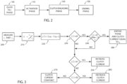
Figure 2 and Figure 3 are two flow charts representing schematically the control executed according to the present invention; and -
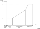
Figure 4 is a diagram of the variation of the control current of a power-take-off clutch over time during the control executed according to the method of the invention. -
Figure 1 schematically represents a work vehicle, preferably an agricultural vehicle such as a tractor, denoted as a whole withreference number 1. -
Work vehicle 1 comprises apowertrain assembly 2, which is carried by a work vehicle body (not illustrated) and is adapted to provide torque to allow motion of the vehicle body with respect to the ground, e.g. thanks to at least one pair of wheels or tracks (not illustrated). - In particular,
powertrain assembly 2 may comprise an engine. For example, said engine may be an internal combustion engine such as a diesel, gasoline or natural gas powered internal combustion engine. - In addition,
powertrain assembly 2 preferably comprises also a drivetrain assembly or transmission assembly, which is operatively interposed between the engine and at least one pair of ground-engaging wheels, in a manner per se known and therefore not further described. - According to the described embodiment,
work vehicle 1 comprises at least one power-take-off (PTO)assembly 4, which is carried by thepowertrain assembly 2 and is adapted to transmit mechanical power to equipment or work implements towed or carried bywork vehicle 1. - More in detail, power-take-off-
assembly 4 may be carried by an engine output shaft, such as an engine crankshaft, and /or by an output shaft of drivetrain assembly, in a manner per se known and therefore not further described. - With reference to the example shown in
Figure 1 , in particular,PTO assembly 4 comprises at least: aninput shaft 6 carried bypowertrain assembly 2; an output shaft 8 adapted to be mechanically connected to the work implement towed or carried bywork vehicle 1; and a hydraulically actuated power-take-off (PTO)clutch 10, which is operatively interposed betweeninput shaft 6 and output shaft 8, and is adapted to selectively engage output shaft 8 toinput shaft 6, in order to transmit mechanical power frompowertrain assembly 2 to output shaft 8 and to the work implement attached thereto. - More in detail, as known,
input shat 6 may be carried by the engine ofwork vehicle 1. - In addition, as always known, output shaft 8 may comprise a splined shaft adapted to be mechanically coupled to the equipment or work implement towed or carried by
work vehicle 1, for instance by means of a universal joint shaft. - With reference to the exemplary embodiment illustrated in
Figure 1 , hydraulically actuatedPTO clutch 10 preferably comprises a multi-plates hydraulically actuated wet clutch. - In addition,
PTO assembly 4 further comprises electrically actuated valve means 12, which are adapted to control the operation of hydraulically actuatedPTO clutch 10. - Preferably, valve means 12 are operatively interposed between a source of pressurized
hydraulic fluid 16 and the hydraulically actuatedPTO clutch 10, and are configured to control/regulate the flow of pressurized hydraulic fluid fed from the source of pressurizedhydraulic fluid 16 to the hydraulically actuatedPTO clutch 10. - More in detail, valve means 12 preferably comprise a solenoid-controlled proportional
hydraulic valve 14. - Preferably,
valve 14 is configured to regulate the pressure of pressurized hydraulic fluid fed towards hydraulic actuatedPTO clutch 10 according to the current applied to asolenoid 18 associated withvalve 14. - By applying a variable current signal to
solenoid 18 ofvalve 14, it is therefore possible to control the pressure of the hydraulic fluid applied to hydraulically actuatedPTO clutch 10. - The relation/proportion between the solenoid current applied on
solenoid 18 and the resulting hydraulic pressure applied onPTO clutch 10 depends onvalve 14 physical characteristics, for instance on valve P/I characteristic (Pressure-Current characteristic), which are well known and therefore are not further discussed. - According to the described embodiment, hydraulically actuated
PTO clutch 10 is preferably configured to transfer a torque frominput shaft 6 to output shaft 8 according to the pressure of the hydraulic fluid applied to the same hydraulic actuatedPTO clutch 10. - Accordingly, the torque transferred from
input shaft 6 to output shaft 8 byPTO clutch 10 will depend on the current signal applied onsolenoid 18 ofvalve 14. - With reference to the exemplary embodiment illustrated in
Figure 1 , in addition,PTO assembly 4 further comprises sensor means 20, which are configured to measure/detect at least the angular velocity of output shaft 8. - In addition, sensor means 20 are preferably configured to also measure/detect the angular velocity of
input shaft 6. - Preferably, sensor means 20 may comprise a first
angular velocity sensor 22, which is associated to inputshaft 6 and is configured to measure the angular velocity of thesame input shaft 6. - Clearly, the angular velocity of
input shaft 6 depends on the rotation speed ofpowertrain assembly 2. For example, the angular velocity ofinput shaft 6 may be equal or directly proportional to the rotation speed of the engine ofwork vehicle 1. - In addition, sensor means 20 preferably comprise also a second
angular velocity sensor 24, which is associated to output shaft 8 and is configured to measure the angular velocity of the same output shaft 8. - In other words, first
angular velocity sensor 22 is preferably configured to measure the angular velocity ofinput shaft 6,upstream PTO clutch 10, and secondangular velocity sensor 24 is preferably configured to measure the angular velocity of output shaft 8,downstream PTO clutch 10. - With reference to the exemplary embodiment illustrated in
Figure 1 ,work vehicle 1 may further comprise aninput device 26, for instance a joystick, a lever, a button, a knob or the like, which is adapted to be operated/handled by a user ofwork vehicle 1 in order to impart control signals adapted to control the engagement ofPTO assembly 4. - More in detail,
input device 26 may be operated/handled bywork vehicle 1 user in order to impart control signals adapted to control the actuation ofPTO clutch 10, in order to selectively engage or disengagePTO assembly 4. - Alternatively, or in addition,
input device 26 may comprise a virtual button embedded on a touch-sensitive screen device carried within the driver's cabin ofwork vehicle 1. - With reference to the exemplary embodiment illustrated in
Figure 1 , in addition,work vehicle 1 is further provided with anelectronic control unit 28, which comprises elaboration means suitable for controlling the operation ofPTO assembly 4 according to a PTO clutch engagement control logic that is described more in detail in the following. -
Electronic control unit 28 may either be the ECU ofwork vehicle 1 or may be separate and distinct fromwork vehicle 1 ECU and may be electronically connected to thesame work vehicle 1 ECU. -
Electronic control unit 28, in particular, is preferably operatively connected at least to sensor means 20 and to valve means 12 ofPTO assembly 4 and is preferably configured to control the actuation of valve means 12 ofPTO clutch 10 according to the engagement control logic that is described more in detail in the following. - Such engagement control logic, for instance, may be deployed into a specific software code, which can be downloaded into the
electronic control unit 28 and is configured to execute the control method as described in the following. - In addition,
electronic control unit 28 may be electrically connected toinput device 26 and may be configured to control the operation ofPTO assembly 4 according to the control signals coming frominput device 26. - More in detail, electronic control unit may be configured to control valve means 12 in order to engage and/or disengage
PTO clutch 10 according to the control signals coming frominput device 26. - The operation of the above-described
PTO assembly 4 is the following. - At an initial condition, suppose that the
PTO assembly 4 is disconnected, meaning that hydraulically actuatedPTO clutch 10 is initially disengaged and valve means 12 are initially closed. - Then, with reference to the example shown in
Figure 2 , supposing that the user handlesinput device 26 to impart a control signal adapted to engagePTO assembly 4 starting from the above initial condition, theelectronic control unit 28 will control valve means 12 as follow. - With reference to
Figures 2 and4 , in a first phase, also referred to as "quick fill phase",electronic control unit 28 will control valve means 12 to open, in order to quickly fillPTO clutch 10 with hydraulic fluid (block 100). - More in detail, in the first phase,
electronic control unit 28 is configured to feed a first pilot current i 1 for a first time interval t1 to valve means 12, in order to feed a high flow of hydraulic fluid towardsPTO clutch 10 and quickly fill this latter. - In even more detail, in the first phase,
electronic control unit 28 is configured to feed the first pilot current i 1 for the first time interval t1 tosolenoid 18, in order to openvalve 14. - Then, in a second phase, also referred to as "activation phase",
electronic control unit 28 will control valve means 12 to modulate the flow of hydraulic fluid towardsPTO clutch 10 until PTO clutch disks come into contact with each other, i.e. until they reach the "kiss point", and the same PTO clutch starts to transfer torque betweeninput shaft 6 and output shaft 8 (block 110). - More in detail, in the second phase
electronic control unit 28 is configured to feed a second pilot current i 2 for a second time interval t2 to valve means 12, in order to feed a controlled flow of hydraulic fluid towardsPTO clutch 10 until PTO clutch disks come into contact with each other, i.e. until kiss point. - In even more detail, in the second phase
electronic control unit 28 is configured to feed the second pilot current i 2 for the second time interval t2 tosolenoid 18, in order to modulate the opening ofvalve 14 and feed a controlled flow of hydraulic fluid towardsPTO clutch 10 until PTO clutch 10 kiss point. - Second time interval t2 for instance may be comprised between 100 milliseconds and 1000 milliseconds, and more precisely it may be equal to about 400 milliseconds.
- Preferably, the magnitude of first pilot current i 1 is greater than the magnitude of second pilot current i 2.
- Then, with reference to
Figure 2 and 3 , in a third phase, also referred to as "clutch engaging phase" or "clutch swapping phase",electronic control unit 28 is configured to recursively control valve means 12 according to a closed-loop control function described in detail in the following (block 120) . - More in detail, during clutch engaging phase,
electronic control unit 28 is preferably configured to recursively control valve means 12 in order to engagePTO assembly 4 in a progressive and stepless manner. - In even more detail, during clutch engaging phase,
electronic control unit 28 is preferably configured to recursively control valve means 12 in order to engage PTO clutch 10 so that output shaft 8 has a constant angular acceleration with respect to inputshaft 6. - In other words, during the clutch engaging phase,
electronic control unit 28 is preferably configured to recursively control valve means 12 in order to engagePTO assembly 4 with a constant variation of the ratio between output shaft 8 angular velocity andinput shaft 6 angular velocity. - According to the disclosed embodiment, in particular, during clutch engaging phase,
electronic control unit 28 is preferably configured to recursively control the pilot current applied to valve means 12, and accordingly the pressure of the hydraulic fluid fed towards PTO clutch 10, on the basis of the angular velocity of output shaft 8 and of the angular velocity ofinput shaft 6. - More in detail,
electronic control unit 28 is configured to retrieve a first value ω1 associated with the angular velocity of input shaft 6 (block 200). - In particular,
electronic control unit 28 is preferably configured to retrieve the first value ω1 from sensor means 20, in particular fromsensor 22. - In addition,
electronic control unit 28 is configured to retrieve a second value ω2 associated with the angular velocity of output shaft 8 (block 200). - In particular,
electronic control unit 28 is preferably configured to retrieve the second value ω2 from sensor means 20, in particular fromsensor 24. - Then, with reference to the example shown in
Figure 3 ,electronic control unit 28 is configured to calculate an angular velocity ratio π by dividing angular velocity ω2 by angular velocity ω1, according to the following mathematical expression:
input shaft 6 and ω2 is the angular velocity of output shaft 8 (block 210). - Then, once calculated the angular velocity ratio π,
electronic control unit 28 is further configured to calculate /determine a quantity Δπ associated to an angular velocity ratio variation of the angular velocity ratio π over time, by subtracting to the value of the angular velocity ratio π(n) at a sampling instant n the value of the angular velocity ratio π(n - 1) at a previous sampling instant n-1, according to the following mathematical expression:
- Then, if such angular velocity ratio variation Δπ is equal to zero, it means that between the two sampling instant n-1 and n considered, the ratio between angular velocity ω2 and angular velocity ω1 has remained constant.
- This may happen when the angular velocity ω2 is equal to the angular velocity ω1, meaning that PTO clutch 10 has engaged and output shaft 8 and
input shaft 6 are spinning/rotating with the same angular velocity. - However, the ratio between angular velocity ω2 and angular velocity ω1 may remain constant also when the variation of angular velocity ω2 is equal to the variation of angular velocity ω1, i.e. when the angular accelerations of
input shaft 6 and of output shaft 8 are the same. In such conditions, however, angular velocity ω2 may not be equal to angular velocity ω1, meaning thatinput shaft 6 and output shaft 8 may be spinning with different angular velocities and PTO clutch may be slipping. - Therefore,
electronic control unit 28 is preferably configured to verify/control if the angular velocity ratio variation Δπ remains equal to zero for third time interval ΔT, such as for example 100 milliseconds (block 240). - In other words,
electronic control unit 28 is preferably configured to verify/control if the angular velocity ratio variation Δπ remains equal to zero for a predetermined number of sampling instants, such as for example 100 sampling instants. - If the angular velocity ratio variation Δπ remains equal to zero for the third time interval ΔT, then it means that the PTO clutch 10 has correctly engaged, and that angular velocity ω2 is equal to angular velocity ω1, i.e. output shaft 8 and
input shaft 6 are spinning/rotating with the same angular velocity. - On the other hand, when the angular velocity ratio variation Δπ is different from zero, it means that PTO clutch 10 has not engaged yet and there is still a difference between angular velocity ω2 and the angular velocity ω1.
- In such case,
electronic control unit 28 is configured to control valve means 12 according to the value of the angular velocity ratio variation Δπ , meaning according to the value of the variation of the ratio between the angular velocity ω2 and angular velocity ω1. - More in detail,
electronic control unit 28 is configured to increase the pilot current applied to valve means 12 and hence the hydraulic pressure exerted on PTO clutch 10 if the angular velocity ratio variation Δπ is lower that a first value/threshold X1 (block 250) . - Conversely,
electronic control unit 28 is configured to decrease the pilot current applied to valve means 12 and hence the hydraulic pressure exerted on PTO clutch 10 if the angular velocity ratio variation Δπ is greater that a second value/threshold X2 (block 260). - Preferably, second threshold X2 is greater than the first threshold X1.
- Alternatively, the first threshold X1 and the second threshold X2 may coincide.
- In addition,
electronic control unit 28 is configured to keep the pilot current applied to valve means 12 constant if the angular velocity ratio variation Δπ falls within the range defined by thresholds X1 and X2 (block 270). - Lastly, in a fourth phase, also referred to as "ending phase", when the angular velocity of output shaft 8 matches the angular velocity of
input shaft 6, meaning that PTO clutch 10 is engaged,electronic control unit 28 will control valve means 12 to remain in the open operation condition, in order to keep PTO clutch 10 engaged (block 130). - More in detail, in the fourth phase,
electronic control unit 28 is configured to feed a fourth pilot current i 4 to valve means 12, in order to keep the same valve means 12 in the open operation condition and maintain PTO clutch 10 engaged (block 280). - Preferably, the magnitude of fourth pilot current i 4 is greater than the magnitude of second pilot current i 2.
- Such operation is schematized in graphics reported in
Figure 4 , which schematically represent the diagram of the pilot current i applied to valve means 12 as function of time during the clutch engaging phase of hydraulically actuated PTO clutch 10. - More in detail, in
Figure 4 it is noticed: - a) the first phase or quick fill phase, wherein pilot current of valve means 12 is equal to value i 1; in such phase, valve means 12 are preferably completely open, to fill PTO clutch 10 with hydraulic fluid;
- b) the second phase or activation phase, wherein pilot current of valve means 12 is equal to value i 2; in such phase valve means 12 are preferably partially open to feed a flow of hydraulic fluid towards PTO clutch 10 until kiss point;
- c) the third phase or clutch engaging phase; and
- d) the fourth phase or ending phase, wherein pilot current of valve means 12 is equal to value i 4; in such phase valve means 12 are kept in the open operation condition to keep PTO clutch 10 engaged.
- According to the above operation and with reference to
Figure 2 and 3 , the present invention is directed to a method for controlling thePTO assembly 4 of awork vehicle 1 as described above and comprising at least the following steps: - i) receiving a signal request to engage
PTO assembly 4; - ii) feeding first pilot current i 1 to valve means 12 for the first time interval t1;
- iii) measuring/determining output shaft 8 angular velocity ω2 (block 200);
- iv) measuring/determining
input shaft 6 angular velocity ω1 (block 200); - v) calculating/determining the angular velocity ratio π by dividing the angular velocity ω2 of output shaft 8 by the angular velocity ω1 of input shaft 6 (block 210);
- vi) calculating/determining the angular velocity ratio variation Δπ of angular velocity ratio π (block 220);
- vii) determining if the angular velocity ratio variation Δπ is equal to zero (block 230);
- viii) if the angular velocity ratio variation Δπ is equal to zero, feeding second pilot current i 4 to valve means 12 in order to keep PTO clutch 10 engaged (block 240); and
- ix) if angular velocity ratio variation Δπ is different from zero, controlling the pilot current supplied to valve means 12 as function of the angular velocity ratio variation Δπ .
- Preferably, the value of first pilot current i 1 is determined so as to open completely valve means 12.
- Moreover, first time interval t1 is calculated/determined in order to fill PTO clutch 10 with hydraulic fluid.
- In addition, the calculation of angular velocity ratio variation Δπ during above step vi) preferably foresees the step of subtracting to the value of the angular velocity ratio π(n) at a sampling instant n the value of the angular velocity ratio π(n - 1) at a previous sampling instant n-1.
- Moreover, according to the disclosed example, above step ix) in turn preferably comprises the steps of:
- x) increasing the pilot current applied to valve means 12 if angular velocity ratio variation Δπ is lower than the first threshold X1 (block 250);
- xi) decreasing the pilot current applied to valve means 12 if angular velocity ratio variation Δπ is higher than the second threshold X2 (block 260); or
- xii) keeping the pilot current applied to valve means 12 constant if angular velocity ratio variation Δπ is greater or equal than the first threshold X1 and at the same time is lower or equal than the second threshold X2 (block 270) .
- Clearly, by increasing or decreasing the pilot current applied valve means 12, the hydraulic pilot pressure applied to PTO clutch 10 increases or decreases accordingly. ,
- In addition, with reference to the example illustrated in
Figure 2 and4 , after above step ii) and before step iii), the method preferably comprises also a step of feeding the second current i 2 to valve means 12 until PTO clutch kiss point, i.e. until disks of PTO clutch 10 comes into contact with each other and PTO clutch 10 starts to transfer torque frominput shaft 6 to output shaft 8. - More in detail, the step of feeding the second current i2 to valve means 12 until kiss point preferably comprises the step of feeding the second current i2 to valve means 12 for the second time interval t2.
- In addition, with reference to the exemplary embodiment illustrated in
Figure 3 , above step viii) preferably comprises the step of verifying/controlling if the angular velocity ratio variation Δπ remains equal to zero for the third time interval ΔT. - In other words, above step viii) preferably comprises the step of verifying/controlling if the angular velocity ratio variation Δπ remains equal to zero for a predetermined number of sampling instants.
- In addition, if the angular velocity ratio variation Δπ remains equal to zero for the third time interval ΔT, the method preferably comprises the step of feeding the second pilot current i 4 to valve means 12 in order to keep PTO clutch 10 engaged (block 240).
- If, on the other hand, the angular velocity ratio variation Δπ does not remain equal to zero for the third time interval ΔT, the method preferably comprises the step of controlling the pilot current supplied to valve means 12 as function of the angular velocity ratio variation Δπ of angular velocity ratio π.
- In other words, if the angular velocity ratio variation Δπ does not remain equal to zero for the third time interval ΔT, the method preferably foresees to carry out above step ix) .
- In view of the foregoing, the advantages of a
work vehicle 1 provided with an apparatus configured to carry out the method according to the present invention are apparent. - In fact, thanks to the proposed method, it is possible to modulate dynamically the
PTO assembly 4 engagement as function of the response of the hydraulically actuated PTO clutch 10 and advantageously as function of the angular acceleration of the output shaft with respect to inputshaft 6 as well. - This allows to engage the
PTO assembly 4 in a smooth and stepless manner, and to compensate for any wear or damage that may occur of PTO clutch 10. Indeed, the pilot current supplied to valve means 12 and hence the pressure of hydraulic fluid fed towards PTO clutch 10 is controlled according to a closed loop control function, which takes into account both the angular velocity ofPTO input shaft 6 and PTO output shaft 8. - More in detail, the proposed method allows to engage
PTO assembly 4 in a progressive and stepless manner, even if the performances of PTO clutch 10 were to vary over the useful lifetime ofwork vehicle 1 due to damages or wear. - In fact, the proposed method allows to dynamically modulate the pilot current supplied to valve means 12 as function of the ratio between the angular velocity of PTO output shaft 8 and the angular velocity of
input shaft 6 and engine during PTO clutch 10 engagement, and hence allows to compensate for any reduction in PTO clutch 10 performances. - In addition, the proposed method allows to ensure that the
PTO assembly 4 engages correctly when required by the user, with all the benefits that this entail. In fact, by modulating the pilot current supplied to valve means 12, it is possible to increase the pressure of the hydraulic fluid fed towards PTO clutch 10, in order to ensure that the same PTO clutch 10 engages correctly even if its performances decreases due to wear or damages. - Lastly, by taking into account also the
input shaft 6 angular velocity when performing the calculation to modulate the pilot current applied to valve means 12, the proposed method allows to account also for any reduction in thepowertrain assembly 2 rotation speed that may occur when engaging thePTO assembly 4, due to the increased load applied on thesame powertrain assembly 2. This allows to optimize the engagement of the PTO clutch 10 and to avoid jerks or oscillation dangerous for the work vehicle operator. - It is clear that modifications can be made to the described apparatus and method which do not extend beyond the scope of protection defined by the claims.
Claims (10)
- A method for controlling the engagement of a power-take-off assembly (4) of a work vehicle (1);said power-take-off assembly (4) being configured to be coupled to a powertrain assembly (2) of said work vehicle (1) for transmitting torque to a work implement carried by said work vehicle (1);said power-take-off assembly (4) comprising at least:• an input shaft (6) adapted to be carried by said powertrain assembly (2);• an output shaft (8) adapted to be connected to said work implement;• a hydraulically actuated power-take-off clutch (10), which is operatively interposed between said input shaft (6) and said output shaft (8), and is adapted to selectively engage said output shaft (8) with said input shaft (6); and• electrically actuated valve means (12), which are operatively interposed between said hydraulically actuated power-take-off clutch (10) and a source of pressurized hydraulic fluid (16), and are configured to control the flow of said pressurized hydraulic fluid fed towards said hydraulically actuated power-take-off clutch (10), in order to control its engagement;said method comprising the following steps:i) receiving a request to engage said power-take-off assembly (4);ii) feeding a first pilot current (i 1) to said valve means (12) for a first time interval (t1);iii) determining a first angular velocity (ω1 ) of said input shaft (6);iv) determining a second angular velocity (ω2 ) of said output shaft (8);v) calculating an angular velocity ratio ( π ) by dividing said second angular velocity (ω2 ) by said first angular velocity (ω1 );vi) calculating an angular velocity ratio variation ( Δπ ) of said angular velocity ratio ( π ) over time;vii) determining if said angular velocity ratio variation ( Δπ ) is equal to zero;viii) if said angular velocity ratio variation ( Δπ ) is equal to zero, feeding a second pilot current (i 4) to said valve means (12) in order to keep said power-take-off clutch (10) engaged; andix) if said angular velocity ratio variation ( Δπ ) is different from zero, controlling the pilot current supplied to said valve means (12) as function of said angular velocity ratio variation ( Δπ ).
- Method according to claim 1, wherein said step vi) comprises the step of subtracting, to the value of said angular velocity ratio ( π(n)) at a sampling instant (n), the value of said angular velocity ratio variation (π(-1)) at a previous sampling instant (n - 1).
- Method according to claim 1 or 2, wherein said step ix) comprises the step of:x) increasing the pilot current applied to said valve means (12) if said angular velocity ratio variation ( Δπ ) is lower than a first threshold (X1); orxi) decreasing the pilot current applied to said valve means (12) if said angular velocity ratio variation ( Δπ ) is greater than a second threshold (X2), wherein said first threshold (X1) is lower or equal to said second threshold (X2).
- Method according to claim 3, wherein said step viii) further comprises the step of:
xii) keeping the pilot current applied to said valve means (12) constant if said angular velocity ratio variation ( Δπ ) is greater or equal than said first threshold (X1) and at the same time is lower or equal than said second threshold (X2). - Method according to any of the preceding claims, further comprising, after said step ii) and before said step iii), the step of feeding a third pilot current (i 2) to said valve means (12) for a second time interval (t2), until disks of hydraulically-actuated power-take-off clutch (10) comes into contact with each other and said power-take-off clutch (10) starts to transfer torque from said input shaft (6) to said output shaft (8).
- Method according to any of the preceding claims, wherein said step viii) comprises the steps of:xiii) verifying if said angular velocity ratio variation ( Δπ ) remains equal to zero for a third time interval (ΔT);xiv) if said angular velocity ratio variation (Δπ ) remains equal to zero for said third time interval (ΔT), feeding said second pilot current (i 4) to said valve means (12) in order to keep said power-take-off clutch (10) engaged; andxv) if said angular velocity ratio variation (Δπ ) does not remain equal to zero for said third time interval (ΔT), controlling the pilot current supplied to said valve means (12) as function of said angular velocity ratio variation ( Δπ ).
- Apparatus for controlling a power-take-off assembly (4) of a work vehicle (1), the apparatus comprising an electronic control unit (28) configured to carry out the method of any of the foregoing claims.
- A work vehicle (1) comprising at least:• a powertrain assembly (2) carried by a work vehicle body and configured to provide torque to allow motion of said work vehicle body with respect to the ground; and• a power-take-off-assembly (4) configured to be coupled to said powertrain assembly (2) for transmitting torque to a work implement carried by said work vehicle (1);said power-take-off assembly (4) comprising:• an input shaft (6) carried by said powertrain assembly (2) ;• an output shaft (8) adapted to be connected to said work implement;• a hydraulically actuated power-take-off clutch (10), which is operatively interposed between said input shaft (6) and said output shaft (8) and is adapted to selectively engage said output shaft (8) with said input shaft (6); and• electrically actuated valve means (12), which are operatively interposed between said hydraulically actuated power-take-off clutch (10) and a source of pressurized hydraulic fluid (16), and are configured to control the flow of said pressurized hydraulic fluid fed towards said hydraulically actuated power-take-off clutch (10), in order to control its engagement;• sensor means (20) configured to detect the angular velocity of said input shaft (6) and/or the angular velocity of said output shaft (8);said work vehicle (1) further comprising an electronic control unit (28), which is operatively connected to said electrically actuated valve means (12) and to said sensor means (20), and is configured to carry out the method of any of claims from 1 to 6.
- A software code comprising instructions which, when executed by electronic control unit of claim 7 or 8, cause said electronic control unit (28) to carry out the method of any of claims from 1 to 6.
- A computer-readable means having stored thereon a software code according to claim 9.
Applications Claiming Priority (1)
| Application Number | Priority Date | Filing Date | Title |
|---|---|---|---|
| IT202300001275 | 2023-01-27 |
Publications (2)
| Publication Number | Publication Date |
|---|---|
| EP4407206A1 true EP4407206A1 (en) | 2024-07-31 |
| EP4407206B1 EP4407206B1 (en) | 2025-09-24 |
Family
ID=85727193
Family Applications (1)
| Application Number | Title | Priority Date | Filing Date |
|---|---|---|---|
| EP24154276.0A Active EP4407206B1 (en) | 2023-01-27 | 2024-01-26 | Improved method and apparatus for controlling a power-take-off assembly of a work vehicle |
Country Status (1)
| Country | Link |
|---|---|
| EP (1) | EP4407206B1 (en) |
Citations (3)
| Publication number | Priority date | Publication date | Assignee | Title |
|---|---|---|---|---|
| US20050217397A1 (en) * | 2004-03-26 | 2005-10-06 | Yanming Hou | Power take-off control system |
| US20180066717A1 (en) * | 2016-09-02 | 2018-03-08 | CNH Industrial America, LLC | System and method for controlling the engagement of a pto clutch for a work vehicle |
| EP4019795A1 (en) * | 2020-12-23 | 2022-06-29 | CNH Industrial Italia S.p.A. | Power take-off assembly for a work vehicle comprising a hydraulic arrangement and a related control method |
-
2024
- 2024-01-26 EP EP24154276.0A patent/EP4407206B1/en active Active
Patent Citations (3)
| Publication number | Priority date | Publication date | Assignee | Title |
|---|---|---|---|---|
| US20050217397A1 (en) * | 2004-03-26 | 2005-10-06 | Yanming Hou | Power take-off control system |
| US20180066717A1 (en) * | 2016-09-02 | 2018-03-08 | CNH Industrial America, LLC | System and method for controlling the engagement of a pto clutch for a work vehicle |
| EP4019795A1 (en) * | 2020-12-23 | 2022-06-29 | CNH Industrial Italia S.p.A. | Power take-off assembly for a work vehicle comprising a hydraulic arrangement and a related control method |
Also Published As
| Publication number | Publication date |
|---|---|
| EP4407206B1 (en) | 2025-09-24 |
Similar Documents
| Publication | Publication Date | Title |
|---|---|---|
| US12391116B2 (en) | Adjustable performance for a vehicle | |
| US8364355B2 (en) | Driving force controller and driving force control method of working vehicle | |
| US20020086769A1 (en) | Arrangement for operating the clutch in the power train of a motor vehicle | |
| US9869355B2 (en) | Adjustable control of power take-off subsystem damping and system thereof | |
| EP3933121A1 (en) | System for controlling a propulsion system of a work or agricultural vehicle | |
| US6508739B1 (en) | System for protecting drive line components from excessive engine inertial forces | |
| US5529548A (en) | Vehicle launch engine fuel control | |
| US20100256877A1 (en) | Transmission control device and method for working vehicle | |
| CA2139137C (en) | Powershift control transmission system with turbo boost monitor | |
| US12049956B2 (en) | Vehicle with continuously variable transmission having operational modes | |
| EP1595734A1 (en) | Vehicle control system, in particular agricultural vehicle | |
| US10710591B2 (en) | Control arrangement for an engine and a hydrostatic transmission of a vehicle | |
| US20180066717A1 (en) | System and method for controlling the engagement of a pto clutch for a work vehicle | |
| US20060293149A1 (en) | Systems and methods for controlling a powertrain | |
| EP4407206B1 (en) | Improved method and apparatus for controlling a power-take-off assembly of a work vehicle | |
| EP1456518B1 (en) | Drive unit for motor vehicle | |
| US20030144110A1 (en) | Method of and apparatus for compensating for the influence of changes of rotational speed upon the characteristic curve of a clutch | |
| US20030186780A1 (en) | Power management system | |
| US4473049A (en) | Throttle modulation mechanism | |
| US20060183595A1 (en) | Centrifugal clutch assembly with dedicated maneuvering mode | |
| US20240309611A1 (en) | Method and system for controlling a propulsion system of a work or agricultural vehicle | |
| EP4299952A1 (en) | Control system of a hydraulic transmission of a work or agricultural vehicle | |
| JPH11166559A (en) | Automatic clutch control device for vehicles | |
| EP2758688A1 (en) | Device and method for control of a motor vehicle's propulsion |
Legal Events
| Date | Code | Title | Description |
|---|---|---|---|
| PUAI | Public reference made under article 153(3) epc to a published international application that has entered the european phase |
Free format text: ORIGINAL CODE: 0009012 |
|
| STAA | Information on the status of an ep patent application or granted ep patent |
Free format text: STATUS: THE APPLICATION HAS BEEN PUBLISHED |
|
| AK | Designated contracting states |
Kind code of ref document: A1 Designated state(s): AL AT BE BG CH CY CZ DE DK EE ES FI FR GB GR HR HU IE IS IT LI LT LU LV MC ME MK MT NL NO PL PT RO RS SE SI SK SM TR |
|
| STAA | Information on the status of an ep patent application or granted ep patent |
Free format text: STATUS: REQUEST FOR EXAMINATION WAS MADE |
|
| 17P | Request for examination filed |
Effective date: 20250131 |
|
| GRAP | Despatch of communication of intention to grant a patent |
Free format text: ORIGINAL CODE: EPIDOSNIGR1 |
|
| STAA | Information on the status of an ep patent application or granted ep patent |
Free format text: STATUS: GRANT OF PATENT IS INTENDED |
|
| INTG | Intention to grant announced |
Effective date: 20250513 |
|
| GRAS | Grant fee paid |
Free format text: ORIGINAL CODE: EPIDOSNIGR3 |
|
| GRAA | (expected) grant |
Free format text: ORIGINAL CODE: 0009210 |
|
| STAA | Information on the status of an ep patent application or granted ep patent |
Free format text: STATUS: THE PATENT HAS BEEN GRANTED |
|
| AK | Designated contracting states |
Kind code of ref document: B1 Designated state(s): AL AT BE BG CH CY CZ DE DK EE ES FI FR GB GR HR HU IE IS IT LI LT LU LV MC ME MK MT NL NO PL PT RO RS SE SI SK SM TR |
|
| REG | Reference to a national code |
Ref country code: GB Ref legal event code: FG4D |
|
| REG | Reference to a national code |
Ref country code: CH Ref legal event code: EP |
|
| REG | Reference to a national code |
Ref country code: DE Ref legal event code: R096 Ref document number: 602024000707 Country of ref document: DE |
|
| REG | Reference to a national code |
Ref country code: IE Ref legal event code: FG4D |
|
| PG25 | Lapsed in a contracting state [announced via postgrant information from national office to epo] |
Ref country code: NO Free format text: LAPSE BECAUSE OF FAILURE TO SUBMIT A TRANSLATION OF THE DESCRIPTION OR TO PAY THE FEE WITHIN THE PRESCRIBED TIME-LIMIT Effective date: 20251224 |
|
| REG | Reference to a national code |
Ref country code: LT Ref legal event code: MG9D |
|
| PG25 | Lapsed in a contracting state [announced via postgrant information from national office to epo] |
Ref country code: FI Free format text: LAPSE BECAUSE OF FAILURE TO SUBMIT A TRANSLATION OF THE DESCRIPTION OR TO PAY THE FEE WITHIN THE PRESCRIBED TIME-LIMIT Effective date: 20250924 |
|
| PG25 | Lapsed in a contracting state [announced via postgrant information from national office to epo] |
Ref country code: HR Free format text: LAPSE BECAUSE OF FAILURE TO SUBMIT A TRANSLATION OF THE DESCRIPTION OR TO PAY THE FEE WITHIN THE PRESCRIBED TIME-LIMIT Effective date: 20250924 |
|
| PG25 | Lapsed in a contracting state [announced via postgrant information from national office to epo] |
Ref country code: GR Free format text: LAPSE BECAUSE OF FAILURE TO SUBMIT A TRANSLATION OF THE DESCRIPTION OR TO PAY THE FEE WITHIN THE PRESCRIBED TIME-LIMIT Effective date: 20251225 |
|
| PG25 | Lapsed in a contracting state [announced via postgrant information from national office to epo] |
Ref country code: SE Free format text: LAPSE BECAUSE OF FAILURE TO SUBMIT A TRANSLATION OF THE DESCRIPTION OR TO PAY THE FEE WITHIN THE PRESCRIBED TIME-LIMIT Effective date: 20250924 |
|
| PG25 | Lapsed in a contracting state [announced via postgrant information from national office to epo] |
Ref country code: LV Free format text: LAPSE BECAUSE OF FAILURE TO SUBMIT A TRANSLATION OF THE DESCRIPTION OR TO PAY THE FEE WITHIN THE PRESCRIBED TIME-LIMIT Effective date: 20250924 |
|
| PG25 | Lapsed in a contracting state [announced via postgrant information from national office to epo] |
Ref country code: BG Free format text: LAPSE BECAUSE OF FAILURE TO SUBMIT A TRANSLATION OF THE DESCRIPTION OR TO PAY THE FEE WITHIN THE PRESCRIBED TIME-LIMIT Effective date: 20250924 |
|
| PG25 | Lapsed in a contracting state [announced via postgrant information from national office to epo] |
Ref country code: RS Free format text: LAPSE BECAUSE OF FAILURE TO SUBMIT A TRANSLATION OF THE DESCRIPTION OR TO PAY THE FEE WITHIN THE PRESCRIBED TIME-LIMIT Effective date: 20251224 |
|
| REG | Reference to a national code |
Ref country code: NL Ref legal event code: MP Effective date: 20250924 |
|
| PG25 | Lapsed in a contracting state [announced via postgrant information from national office to epo] |
Ref country code: NL Free format text: LAPSE BECAUSE OF FAILURE TO SUBMIT A TRANSLATION OF THE DESCRIPTION OR TO PAY THE FEE WITHIN THE PRESCRIBED TIME-LIMIT Effective date: 20250924 |
|
| REG | Reference to a national code |
Ref country code: AT Ref legal event code: MK05 Ref document number: 1840534 Country of ref document: AT Kind code of ref document: T Effective date: 20250924 |
|
| PG25 | Lapsed in a contracting state [announced via postgrant information from national office to epo] |
Ref country code: SM Free format text: LAPSE BECAUSE OF FAILURE TO SUBMIT A TRANSLATION OF THE DESCRIPTION OR TO PAY THE FEE WITHIN THE PRESCRIBED TIME-LIMIT Effective date: 20250924 |
|
| PG25 | Lapsed in a contracting state [announced via postgrant information from national office to epo] |
Ref country code: ES Free format text: LAPSE BECAUSE OF FAILURE TO SUBMIT A TRANSLATION OF THE DESCRIPTION OR TO PAY THE FEE WITHIN THE PRESCRIBED TIME-LIMIT Effective date: 20250924 |
|
| PGFP | Annual fee paid to national office [announced via postgrant information from national office to epo] |
Ref country code: DE Payment date: 20260127 Year of fee payment: 3 |
|
| PG25 | Lapsed in a contracting state [announced via postgrant information from national office to epo] |
Ref country code: AT Free format text: LAPSE BECAUSE OF FAILURE TO SUBMIT A TRANSLATION OF THE DESCRIPTION OR TO PAY THE FEE WITHIN THE PRESCRIBED TIME-LIMIT Effective date: 20250924 |
|
| PGFP | Annual fee paid to national office [announced via postgrant information from national office to epo] |
Ref country code: IT Payment date: 20260131 Year of fee payment: 3 |
|
| PG25 | Lapsed in a contracting state [announced via postgrant information from national office to epo] |
Ref country code: IS Free format text: LAPSE BECAUSE OF FAILURE TO SUBMIT A TRANSLATION OF THE DESCRIPTION OR TO PAY THE FEE WITHIN THE PRESCRIBED TIME-LIMIT Effective date: 20260124 |
|
| PGFP | Annual fee paid to national office [announced via postgrant information from national office to epo] |
Ref country code: FR Payment date: 20260126 Year of fee payment: 3 |
|
| PG25 | Lapsed in a contracting state [announced via postgrant information from national office to epo] |
Ref country code: CZ Free format text: LAPSE BECAUSE OF FAILURE TO SUBMIT A TRANSLATION OF THE DESCRIPTION OR TO PAY THE FEE WITHIN THE PRESCRIBED TIME-LIMIT Effective date: 20250924 Ref country code: PT Free format text: LAPSE BECAUSE OF FAILURE TO SUBMIT A TRANSLATION OF THE DESCRIPTION OR TO PAY THE FEE WITHIN THE PRESCRIBED TIME-LIMIT Effective date: 20260126 |
|
| PG25 | Lapsed in a contracting state [announced via postgrant information from national office to epo] |
Ref country code: PL Free format text: LAPSE BECAUSE OF FAILURE TO SUBMIT A TRANSLATION OF THE DESCRIPTION OR TO PAY THE FEE WITHIN THE PRESCRIBED TIME-LIMIT Effective date: 20250924 |
|
| PG25 | Lapsed in a contracting state [announced via postgrant information from national office to epo] |
Ref country code: EE Free format text: LAPSE BECAUSE OF FAILURE TO SUBMIT A TRANSLATION OF THE DESCRIPTION OR TO PAY THE FEE WITHIN THE PRESCRIBED TIME-LIMIT Effective date: 20250924 Ref country code: SK Free format text: LAPSE BECAUSE OF FAILURE TO SUBMIT A TRANSLATION OF THE DESCRIPTION OR TO PAY THE FEE WITHIN THE PRESCRIBED TIME-LIMIT Effective date: 20250924 |
|
| REG | Reference to a national code |
Ref country code: DE Ref legal event code: R097 Ref document number: 602024000707 Country of ref document: DE |
|
| PG25 | Lapsed in a contracting state [announced via postgrant information from national office to epo] |
Ref country code: LT Free format text: LAPSE BECAUSE OF FAILURE TO SUBMIT A TRANSLATION OF THE DESCRIPTION OR TO PAY THE FEE WITHIN THE PRESCRIBED TIME-LIMIT Effective date: 20250924 |
|
| PG25 | Lapsed in a contracting state [announced via postgrant information from national office to epo] |
Ref country code: DK Free format text: LAPSE BECAUSE OF FAILURE TO SUBMIT A TRANSLATION OF THE DESCRIPTION OR TO PAY THE FEE WITHIN THE PRESCRIBED TIME-LIMIT Effective date: 20250924 |
|
| PLBE | No opposition filed within time limit |
Free format text: ORIGINAL CODE: 0009261 |
|
| STAA | Information on the status of an ep patent application or granted ep patent |
Free format text: STATUS: NO OPPOSITION FILED WITHIN TIME LIMIT |
|
| REG | Reference to a national code |
Ref country code: CH Ref legal event code: L10 Free format text: ST27 STATUS EVENT CODE: U-0-0-L10-L00 (AS PROVIDED BY THE NATIONAL OFFICE) Effective date: 20260805 |