EP4407164A1 - Split evaporator for steam injection turbine engine - Google Patents
Split evaporator for steam injection turbine engine Download PDFInfo
- Publication number
- EP4407164A1 EP4407164A1 EP24154536.7A EP24154536A EP4407164A1 EP 4407164 A1 EP4407164 A1 EP 4407164A1 EP 24154536 A EP24154536 A EP 24154536A EP 4407164 A1 EP4407164 A1 EP 4407164A1
- Authority
- EP
- European Patent Office
- Prior art keywords
- flow
- water
- evaporator
- assembly
- turbine
- Prior art date
- Legal status (The legal status is an assumption and is not a legal conclusion. Google has not performed a legal analysis and makes no representation as to the accuracy of the status listed.)
- Pending
Links
- 238000010793 Steam injection (oil industry) Methods 0.000 title description 2
- XLYOFNOQVPJJNP-UHFFFAOYSA-N water Substances O XLYOFNOQVPJJNP-UHFFFAOYSA-N 0.000 claims abstract description 108
- 238000002347 injection Methods 0.000 claims abstract description 5
- 239000007924 injection Substances 0.000 claims abstract description 5
- 239000007789 gas Substances 0.000 claims description 43
- 238000010438 heat treatment Methods 0.000 claims description 32
- 239000000446 fuel Substances 0.000 claims description 21
- 238000011144 upstream manufacturing Methods 0.000 claims description 17
- 229910052739 hydrogen Inorganic materials 0.000 claims description 10
- 239000001257 hydrogen Substances 0.000 claims description 10
- UFHFLCQGNIYNRP-UHFFFAOYSA-N Hydrogen Chemical compound [H][H] UFHFLCQGNIYNRP-UHFFFAOYSA-N 0.000 claims description 9
- 239000007788 liquid Substances 0.000 claims description 8
- 238000000034 method Methods 0.000 claims description 6
- 238000001816 cooling Methods 0.000 abstract description 17
- 238000011084 recovery Methods 0.000 description 6
- 230000009466 transformation Effects 0.000 description 3
- OKTJSMMVPCPJKN-UHFFFAOYSA-N Carbon Chemical compound [C] OKTJSMMVPCPJKN-UHFFFAOYSA-N 0.000 description 2
- 229910052799 carbon Inorganic materials 0.000 description 2
- 230000006835 compression Effects 0.000 description 2
- 238000007906 compression Methods 0.000 description 2
- 230000005494 condensation Effects 0.000 description 2
- 238000009833 condensation Methods 0.000 description 2
- 238000005461 lubrication Methods 0.000 description 2
- 230000000712 assembly Effects 0.000 description 1
- 238000000429 assembly Methods 0.000 description 1
- 238000004891 communication Methods 0.000 description 1
- 230000008030 elimination Effects 0.000 description 1
- 238000003379 elimination reaction Methods 0.000 description 1
- 239000000284 extract Substances 0.000 description 1
- 150000002431 hydrogen Chemical class 0.000 description 1
- 239000000203 mixture Substances 0.000 description 1
- 238000012986 modification Methods 0.000 description 1
- 230000004048 modification Effects 0.000 description 1
- 230000009467 reduction Effects 0.000 description 1
- 230000001131 transforming effect Effects 0.000 description 1
- 239000002918 waste heat Substances 0.000 description 1
- 239000002699 waste material Substances 0.000 description 1
Images


Classifications
-
- F—MECHANICAL ENGINEERING; LIGHTING; HEATING; WEAPONS; BLASTING
- F02—COMBUSTION ENGINES; HOT-GAS OR COMBUSTION-PRODUCT ENGINE PLANTS
- F02C—GAS-TURBINE PLANTS; AIR INTAKES FOR JET-PROPULSION PLANTS; CONTROLLING FUEL SUPPLY IN AIR-BREATHING JET-PROPULSION PLANTS
- F02C3/00—Gas-turbine plants characterised by the use of combustion products as the working fluid
- F02C3/20—Gas-turbine plants characterised by the use of combustion products as the working fluid using a special fuel, oxidant, or dilution fluid to generate the combustion products
- F02C3/30—Adding water, steam or other fluids for influencing combustion, e.g. to obtain cleaner exhaust gases
-
- F—MECHANICAL ENGINEERING; LIGHTING; HEATING; WEAPONS; BLASTING
- F02—COMBUSTION ENGINES; HOT-GAS OR COMBUSTION-PRODUCT ENGINE PLANTS
- F02C—GAS-TURBINE PLANTS; AIR INTAKES FOR JET-PROPULSION PLANTS; CONTROLLING FUEL SUPPLY IN AIR-BREATHING JET-PROPULSION PLANTS
- F02C3/00—Gas-turbine plants characterised by the use of combustion products as the working fluid
- F02C3/20—Gas-turbine plants characterised by the use of combustion products as the working fluid using a special fuel, oxidant, or dilution fluid to generate the combustion products
- F02C3/22—Gas-turbine plants characterised by the use of combustion products as the working fluid using a special fuel, oxidant, or dilution fluid to generate the combustion products the fuel or oxidant being gaseous at standard temperature and pressure
-
- F—MECHANICAL ENGINEERING; LIGHTING; HEATING; WEAPONS; BLASTING
- F02—COMBUSTION ENGINES; HOT-GAS OR COMBUSTION-PRODUCT ENGINE PLANTS
- F02C—GAS-TURBINE PLANTS; AIR INTAKES FOR JET-PROPULSION PLANTS; CONTROLLING FUEL SUPPLY IN AIR-BREATHING JET-PROPULSION PLANTS
- F02C3/00—Gas-turbine plants characterised by the use of combustion products as the working fluid
- F02C3/20—Gas-turbine plants characterised by the use of combustion products as the working fluid using a special fuel, oxidant, or dilution fluid to generate the combustion products
- F02C3/30—Adding water, steam or other fluids for influencing combustion, e.g. to obtain cleaner exhaust gases
- F02C3/305—Increasing the power, speed, torque or efficiency of a gas turbine or the thrust of a turbojet engine by injecting or adding water, steam or other fluids
-
- F—MECHANICAL ENGINEERING; LIGHTING; HEATING; WEAPONS; BLASTING
- F02—COMBUSTION ENGINES; HOT-GAS OR COMBUSTION-PRODUCT ENGINE PLANTS
- F02C—GAS-TURBINE PLANTS; AIR INTAKES FOR JET-PROPULSION PLANTS; CONTROLLING FUEL SUPPLY IN AIR-BREATHING JET-PROPULSION PLANTS
- F02C6/00—Plural gas-turbine plants; Combinations of gas-turbine plants with other apparatus; Adaptations of gas-turbine plants for special use
- F02C6/18—Plural gas-turbine plants; Combinations of gas-turbine plants with other apparatus; Adaptations of gas-turbine plants for special use using the waste heat of gas-turbine plants outside the plants themselves, e.g. gas-turbine power heat plants
-
- F—MECHANICAL ENGINEERING; LIGHTING; HEATING; WEAPONS; BLASTING
- F02—COMBUSTION ENGINES; HOT-GAS OR COMBUSTION-PRODUCT ENGINE PLANTS
- F02C—GAS-TURBINE PLANTS; AIR INTAKES FOR JET-PROPULSION PLANTS; CONTROLLING FUEL SUPPLY IN AIR-BREATHING JET-PROPULSION PLANTS
- F02C7/00—Features, components parts, details or accessories, not provided for in, or of interest apart form groups F02C1/00 - F02C6/00; Air intakes for jet-propulsion plants
- F02C7/12—Cooling of plants
- F02C7/14—Cooling of plants of fluids in the plant, e.g. lubricant or fuel
-
- F—MECHANICAL ENGINEERING; LIGHTING; HEATING; WEAPONS; BLASTING
- F05—INDEXING SCHEMES RELATING TO ENGINES OR PUMPS IN VARIOUS SUBCLASSES OF CLASSES F01-F04
- F05D—INDEXING SCHEME FOR ASPECTS RELATING TO NON-POSITIVE-DISPLACEMENT MACHINES OR ENGINES, GAS-TURBINES OR JET-PROPULSION PLANTS
- F05D2220/00—Application
- F05D2220/30—Application in turbines
- F05D2220/32—Application in turbines in gas turbines
- F05D2220/323—Application in turbines in gas turbines for aircraft propulsion, e.g. jet engines
-
- F—MECHANICAL ENGINEERING; LIGHTING; HEATING; WEAPONS; BLASTING
- F05—INDEXING SCHEMES RELATING TO ENGINES OR PUMPS IN VARIOUS SUBCLASSES OF CLASSES F01-F04
- F05D—INDEXING SCHEME FOR ASPECTS RELATING TO NON-POSITIVE-DISPLACEMENT MACHINES OR ENGINES, GAS-TURBINES OR JET-PROPULSION PLANTS
- F05D2260/00—Function
- F05D2260/20—Heat transfer, e.g. cooling
- F05D2260/213—Heat transfer, e.g. cooling by the provision of a heat exchanger within the cooling circuit
-
- F—MECHANICAL ENGINEERING; LIGHTING; HEATING; WEAPONS; BLASTING
- F05—INDEXING SCHEMES RELATING TO ENGINES OR PUMPS IN VARIOUS SUBCLASSES OF CLASSES F01-F04
- F05D—INDEXING SCHEME FOR ASPECTS RELATING TO NON-POSITIVE-DISPLACEMENT MACHINES OR ENGINES, GAS-TURBINES OR JET-PROPULSION PLANTS
- F05D2260/00—Function
- F05D2260/20—Heat transfer, e.g. cooling
- F05D2260/232—Heat transfer, e.g. cooling characterized by the cooling medium
- F05D2260/2322—Heat transfer, e.g. cooling characterized by the cooling medium steam
-
- F—MECHANICAL ENGINEERING; LIGHTING; HEATING; WEAPONS; BLASTING
- F05—INDEXING SCHEMES RELATING TO ENGINES OR PUMPS IN VARIOUS SUBCLASSES OF CLASSES F01-F04
- F05D—INDEXING SCHEME FOR ASPECTS RELATING TO NON-POSITIVE-DISPLACEMENT MACHINES OR ENGINES, GAS-TURBINES OR JET-PROPULSION PLANTS
- F05D2270/00—Control
- F05D2270/01—Purpose of the control system
- F05D2270/08—Purpose of the control system to produce clean exhaust gases
Definitions
- the present disclosure relates generally to a steam injected aircraft propulsion system and, more particularly to an evaporator for producing a steam flow for injection.
- Gas turbine engines compress incoming core airflow, mix the compressed airflow with fuel that is ignited in a combustor to generate a high energy exhaust gas flow. Some energy in the high energy exhaust flow is recovered as it is expanded through a turbine section. Even with the use of alternate fuels, a large amount of energy in the form of heat is simply exhausted from the turbine section to the atmosphere. The lost heat reduces the overall efficiency of the engine.
- Lost heat can be utilized to generate a steam flow from water recovered from the exhaust gas flow.
- the steam can be injected into the core flow stream to increase mass flow and thereby increase energy efficiency. Transformation of the water to steam is provided by an evaporator.
- the evaporator also provides for cooling of the exhaust gas flow to aid in condensation. Accordingly, evaporator operation impacts improvements in engine efficiency provided by steam injection.
- a turbine engine assembly includes a core engine including a core flow path where air is compressed in a compressor section, communicated to a combustor section, mixed with fuel, and ignited to generate an exhaust gas flow that is expanded through a turbine section, a condenser assembly arranged along the core flow path to extract water from the exhaust gas flow, and an evaporator assembly where thermal energy from the exhaust gas flow is communicated to the water extracted by the condenser assembly to generate a steam flow for injection into the core flow path.
- the evaporator assembly includes a first inlet for a first flow of water and a second inlet for a second flow of water upstream of the first inlet.
- a spacing between a last stage of the turbine section and the first inlet is greater than a spacing between the last stage of the turbine section and the second inlet.
- evaporator includes a first outlet and a second outlet, wherein the second outlet is upstream of the first outlet and a flow of water from the first outlet is combined with the second flow of water communicated to the second inlet.
- the second flow of water into the evaporator is a higher temperature than the first inlet flow of water in the evaporator.
- the steam temperature exiting the evaporator assembly is between 550 (288 °C) and 1500 F (816 °C).
- an intercooler upstream of the second inlet where the preheated second water flow is cooled prior to entering the evaporator assembly.
- the evaporator assembly includes a first evaporator portion disposed upstream of a turbine section and a second evaporator portion disposed downstream of a turbine section.
- the turbine section includes a first turbine and a second turbine and the first evaporator assembly is disposed between the first turbine and the second turbine and the second evaporator assembly is disposed after the second turbine.
- the condenser assembly includes a condenser portion where water from the exhaust gas flow is condensed into a liquid and a water separator where the liquid is separated from the exhaust gas flow.
- At least a portion of water extracted by the condenser assembly is communicated to a location upstream of the combustor.
- At least a portion of the steam flow is injected into the combustor section.
- a turbine engine assembly includes a core engine including a core flow path where air is compressed in a compressor section, communicated to a combustor section, mixed with fuel, and ignited to generate an exhaust gas flow that is expanded through a turbine section, a hydrogen fuel system suppling hydrogen fuel to the combustor through a fuel flow path, a condenser assembly arranged along a core flow path to extract water from the exhaust flow, and an evaporator assembly where thermal energy from the exhaust gas flow is communicated to the water extracted by the condenser assembly to generate a steam flow for injection into the core flow path.
- the evaporator assembly including a first water heating circuit for heating a first water flow and a second water heating circuit for transforming a second water flow into a steam flow.
- the first water heating circuit is located downstream further from the combustor than the second water circuit.
- the evaporator assembly includes a first evaporator portion disposed aft of a last portion of the turbine section and a second evaporator portion disposed forward of at least one portion of the turbine section, the second water heating circuit disposed in the second evaporator portion and the first water circuit disposed in the first evaporator portion.
- a method of generating a steam flow in a turbine engine assembly includes extracting water from an exhaust gas flow, communicating a first flow of the extracted water to a first heating circuit of an evaporator exposed to the exhaust gas flow, communicating a second flow of the extracted water to a second heating circuit of an evaporator exposed to the exhaust gas flow, wherein the second heating circuit is in a hotter portion of the exhaust gas flow, directing heated water flow from the first heating circuit into the second heating circuit, heating the water flow in the second heating circuit to generate a steam flow, and communicating the generated steam flow to a core flow path of the turbine engine.
- the first flow in the first circuit generates steam and the second heating circuit generates a superheated steam flow.
- the method includes heating the second flow of extracted water with at least one heat load to preheat the second flow prior to entering the evaporator.
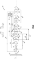
- FIG. 1 schematically illustrates an example hydrogen steam injected turbine engine that is generally indicated at 20.
- the disclosed turbine engine 20 includes an evaporator assembly 34 to efficiently utilize heat from an exhaust gas flow 50 to generate a steam flow injected into a combustor 26.
- the evaporator assembly 34 splits steam generation and cooling functions to increase efficiencies of each function.
- the engine 20 includes core engine with a core flow path through a fan 22, a compressor section 24, the combustor 26 and a turbine section 28.
- the fan 22 drives inlet air as a core flow 48 into the compressor section 24.
- the core flow 48 is compressed and communicated to the combustor 26.
- the core flow 48 is mixed with a fuel flow 66 and ignited to generate a high energy gas flow 50 that expands through the turbine section 28 where energy is extracted and utilized to drive the fan 22 and the compressor section 24.
- a bypass flow 52 may flow through the fan 22 and bypass the remaining components of the engine 20.
- the engine 20 is configured to burn a non-carbon based fuel to reduce engine emissions.
- the fuel is hydrogen based and provided by a fuel system 42.
- the example fuel system 42 includes a liquid hydrogen (LH 2 ) tank 44 in communication with at least one pump 46.
- the pump 46 drives the fuel flow 66 to the combustor 26.
- hydrogen is disclosed by way of example, other fuels could be utilized within the contemplation of this disclosure.
- a steam flow 56 from an evaporator assembly 34 is injected into the core air flow at or upstream of the combustor 26.
- the steam flow 56 increases mass flow through the turbine section 28 to improve engine efficiency.
- the high energy gas flow 50 is exhausted from the turbine section 28 and communicated to an evaporator assembly 34 and a water recovery assembly 40 before being exhausted to the atmosphere.
- the evaporator assembly 34 functions to generate the steam flow 56 from water recovered from the exhaust gas flow 50.
- the evaporator 34 further provides cooling of the exhaust gas flow 50 to aid in condensation of liquid from the exhaust gas flow 50.
- the evaporator assembly is hottest at the upstream most portion adjacent the aft end of the turbine section 28.
- the coolest portion of the evaporator assembly 34 is that portion that is furthest or downstream from the turbine section 28.
- the example evaporator assembly 34 advantageously routes water flow relative to the hottest and coolest portions to maximize both the cooling and heating functions.
- Upstream as utilized in this disclosure is in a direction indicated by arrow 100 toward the fan section 22 and counter to the core flow 48. Downstream as utilized in this disclosure is in the direction indicated by arrow 102 toward the water recovery assembly 40 and in the same direction as the core flow 48 and exhaust gas flow 50.
- the water recovery assembly 40 draws water, schematically indicated at 54, from the high energy gas flow 50 and communicates the recovered water to water storage tank 58.
- the water storage tank 58 operates as an accumulator to provide sufficient water for operation during various engine operating conditions.
- the water flow 54 is split between a first evaporator portion 36 downstream from a second evaporator portion 38. The positions of the first evaporator portion 36 and the second evaporator portion 38 relative to the turbine section 28 provide for the second evaporator 38 to be much hotter than the first evaporator 36.
- the first evaporator portion 36 includes a first inlet 68 to a first water heating circuit 60 and the second evaporator portion 38 includes a second inlet 70 to a second water heating circuit 62.
- Heated water and/or steam is exhausted through a first outlet 72 after being heated in the first evaporator portion 36.
- Steam 56 is exhausted from a second outlet 74 after being heated in the second evaporator portion 38.
- the steam temperature exiting the evaporator assembly is between 550 (288 °C) and 1500 F (816 °C). The steam 56 is communicated to the combustor 26.
- Water directed to the second evaporator portion 38 is first routed to cool a heat load 64 where the water is preheated.
- the relatively cool water from the water recovery assembly 40 provides for cooling the heat load 64 before being communicated to the second evaporator portion 38.
- the heat load 64 is shown schematically and would include a heat exchanger associated with an engine or aircraft system that required cooling. Such heat loads can include electrical components, cooling air systems, lubrication system and any other system or flow that requires cooling.
- the heat load 64 would include an applicable heat exchanger that is configured to reject heat into the water flow.
- Preheated water from the first water heating circuit 60 of the first evaporator portion 36 is also combined with water flow to the second evaporator portion 38.
- the preheated water communicated to the second evaporator portion 38 provides more efficient transformation into steam.
- a first water flow 88 is communicated to the inlet 68 of the first evaporator 36.
- the first water flow 88 is heated and exhausted as a preheated water flow indicated at 96.
- the preheated water flow 96 is combined with a second water flow 90 that is first routed to cool the first heat load 64. Accordingly, the second water flow 90 is already warmed and is combined with the preheated water 96 from the first evaporator portion 36.
- the second water flow 90 and the preheated water flow 96 are combined and communicated through the second inlet 70 into the hotter second evaporator portion 38.
- Heat rejection from the exhaust gas flow 50 into the second evaporator section 38 provides for lower core flow temperatures into the first evaporator section 36.
- the first evaporator portion 36 is spaced apart from the turbine section 28 a distance 94.
- the second evaporator portion 38 is spaced apart from the turbine section 28 a distance 92 that is less than the first distance 94. The different distances correspond to the different operating temperatures of each evaporator portion 36, 38.
- the exhaust gas flow 50 is first flowed through the second evaporator portion 38 where it is cooled by rejecting heat into the combined water flow to generate steam.
- the cooler gas flow from the second evaporator 38 is communicated to the first evaporator 36 where it is further cooled to generate a cooled exhaust gas flow 82 that is communicated to a condenser 78 of the water recovery assembly 40.
- the cooled exhaust gas flow 82 is further cooled to extract liquid water and is communicated as a liquid/gas flow 84 to a water separator 80.
- the water separator 80 extracts water and expels the remaining portion of the exhaust gas flow as indicated at 86.
- the water flow from the water separator 80 is split into the first water flow 88 and the second water flow 90.
- the example evaporator portions 36, 38 are disclosed and illustrated as separate components, however, both portions could be configured as different passes through a single unit with separate water heating circuits.
- a portion of the water flow is provided upstream to the compressor section 24 for intercooling.
- An intercooling flow of water 76 provides for improved compressor performance.
- intercooling of the compressor section 24 is shown and disclosed by way of example, the flow of water 76 could be utilized for other engine cooling functions.
- FIG. 3 another disclosed example engine embodiment is shown and indicated at 25 and includes an intercooling heat exchanger 98 that receives a water flow 90 from the heat load 64.
- the intercooler heat exchanger 98 may provide cooling for any heat load on the engine or aircraft, such as a heat load from cooling air passing from one stage of compression to a higher pressure stage of compression.
- the intercooler heat exchanger 98 may provide cooling for a cooled cooling air system, a compressor intercooling system, cooling of a lubrication system or any other system or component that operates better when cooled.
- a combined water flow indicated at 104 includes preheated water from the first evaporator 36, from the heat load 64 and from the intercooler heat exchanger 98. The preheating of the combined water flow 104 enables a greater amount of steam generation than if all the thermal energy required for transformation was provided only by the second evaporator 38.
- FIG. 4 another disclosed example engine embodiment is shown and indicated at 35 and includes the second evaporator 38 disposed between turbine sections 30 and 32.
- the second evaporator 38 is disposed between the high pressure turbine section 30 and the low pressure turbine section 32.
- the exhaust gas flow 50 communicated to the second evaporator portion 38 is therefore much hotter than the gas flow exhausted from the low pressure turbine section 32.
- the higher temperature gas flow 50 further improves the generation and superheating temperature of the steam flow 56.
- the first evaporator portion 36 is disposed aft and downstream of the last turbine section 32.
- the disclosed example embodiment shows the second evaporator portion 38 disposed between the high pressure turbine 30 and the low pressure turbine 32, the second evaporator 38 may be located anywhere within the turbine section 28 upstream of at least one turbine section. Moreover, the first evaporator portion 36 may be disposed anywhere aft of a last portion of the turbine section 28.
- the disclosed evaporator assemblies provide improved heating and cooling functions by providing separate portions that can be individually tailored to maximize steam generation and exhaust gas cooling.
Landscapes
- Engineering & Computer Science (AREA)
- Chemical & Material Sciences (AREA)
- Combustion & Propulsion (AREA)
- Mechanical Engineering (AREA)
- General Engineering & Computer Science (AREA)
- Engine Equipment That Uses Special Cycles (AREA)
Abstract
A turbine engine assembly (20) includes a condenser assembly (78) arranged along a core flow path to extract water from an exhaust gas flow (50), and an evaporator assembly (34) where thermal energy from the exhaust gas flow (50) is communicated to the water extracted by the condenser assembly (78) to generate a steam flow (56) for injection into the core flow path. The evaporator assembly (34) splits steam generation and cooling functions to increase efficiencies of each function.
Description
- The present disclosure relates generally to a steam injected aircraft propulsion system and, more particularly to an evaporator for producing a steam flow for injection.
- Reduction and/or elimination of carbon emissions generated by aircraft operation is a stated goal of aircraft manufacturers and airline operators. Gas turbine engines compress incoming core airflow, mix the compressed airflow with fuel that is ignited in a combustor to generate a high energy exhaust gas flow. Some energy in the high energy exhaust flow is recovered as it is expanded through a turbine section. Even with the use of alternate fuels, a large amount of energy in the form of heat is simply exhausted from the turbine section to the atmosphere. The lost heat reduces the overall efficiency of the engine.
- Lost heat can be utilized to generate a steam flow from water recovered from the exhaust gas flow. The steam can be injected into the core flow stream to increase mass flow and thereby increase energy efficiency. Transformation of the water to steam is provided by an evaporator. The evaporator also provides for cooling of the exhaust gas flow to aid in condensation. Accordingly, evaporator operation impacts improvements in engine efficiency provided by steam injection.
- A turbine engine assembly according to aspect of the present invention includes a core engine including a core flow path where air is compressed in a compressor section, communicated to a combustor section, mixed with fuel, and ignited to generate an exhaust gas flow that is expanded through a turbine section, a condenser assembly arranged along the core flow path to extract water from the exhaust gas flow, and an evaporator assembly where thermal energy from the exhaust gas flow is communicated to the water extracted by the condenser assembly to generate a steam flow for injection into the core flow path. The evaporator assembly includes a first inlet for a first flow of water and a second inlet for a second flow of water upstream of the first inlet.
- In an embodiment according to the previous aspect, a spacing between a last stage of the turbine section and the first inlet is greater than a spacing between the last stage of the turbine section and the second inlet.
- In an embodiment according to any of the previous aspects or embodiments, evaporator includes a first outlet and a second outlet, wherein the second outlet is upstream of the first outlet and a flow of water from the first outlet is combined with the second flow of water communicated to the second inlet.
- In an embodiment according to any of the previous aspects or embodiments, further includes at least one heat load upstream of a flow of water from the second inlet where the second water flow is preheated before entering the evaporator assembly.
- In an embodiment according to any of the previous aspects or embodiments, the second flow of water into the evaporator is a higher temperature than the first inlet flow of water in the evaporator.
- In an embodiment according to any of the previous aspects or embodiments, the steam temperature exiting the evaporator assembly is between 550 (288 °C) and 1500 F (816 °C).
- In an embodiment according to any of the previous aspects or embodiments, an intercooler upstream of the second inlet where the preheated second water flow is cooled prior to entering the evaporator assembly.
- In an embodiment according to any of the previous aspects or embodiments, the evaporator assembly includes a first evaporator portion disposed upstream of a turbine section and a second evaporator portion disposed downstream of a turbine section.
- In an embodiment according to any of the previous aspects or embodiments, the turbine section includes a first turbine and a second turbine and the first evaporator assembly is disposed between the first turbine and the second turbine and the second evaporator assembly is disposed after the second turbine.
- In an embodiment according to any of the previous aspects or embodiments, the condenser assembly includes a condenser portion where water from the exhaust gas flow is condensed into a liquid and a water separator where the liquid is separated from the exhaust gas flow.
- In an embodiment according to any of the previous aspects or embodiments, at least a portion of water extracted by the condenser assembly is communicated to a location upstream of the combustor.
- In an embodiment according to any of the previous aspects or embodiments, at least a portion of the steam flow is injected into the combustor section.
- In an embodiment according to any of the previous aspects or embodiments, including a hydrogen fuel system suppling hydrogen fuel to the combustor through a fuel flow path.
- A turbine engine assembly according to another aspect of the present invention includes a core engine including a core flow path where air is compressed in a compressor section, communicated to a combustor section, mixed with fuel, and ignited to generate an exhaust gas flow that is expanded through a turbine section, a hydrogen fuel system suppling hydrogen fuel to the combustor through a fuel flow path, a condenser assembly arranged along a core flow path to extract water from the exhaust flow, and an evaporator assembly where thermal energy from the exhaust gas flow is communicated to the water extracted by the condenser assembly to generate a steam flow for injection into the core flow path. The evaporator assembly including a first water heating circuit for heating a first water flow and a second water heating circuit for transforming a second water flow into a steam flow.
- In an embodiment according to any of the previous aspects or embodiments, the first water heating circuit is located downstream further from the combustor than the second water circuit.
- In an embodiment according to any of the previous aspects or embodiments, including at least one heat load where a second water flow is preheated before entering the second heating circuit of the evaporator assembly.
- In an embodiment according to any of the previous aspects or embodiments, the evaporator assembly includes a first evaporator portion disposed aft of a last portion of the turbine section and a second evaporator portion disposed forward of at least one portion of the turbine section, the second water heating circuit disposed in the second evaporator portion and the first water circuit disposed in the first evaporator portion.
- A method of generating a steam flow in a turbine engine assembly according to another aspect of the present invention includes extracting water from an exhaust gas flow, communicating a first flow of the extracted water to a first heating circuit of an evaporator exposed to the exhaust gas flow, communicating a second flow of the extracted water to a second heating circuit of an evaporator exposed to the exhaust gas flow, wherein the second heating circuit is in a hotter portion of the exhaust gas flow, directing heated water flow from the first heating circuit into the second heating circuit, heating the water flow in the second heating circuit to generate a steam flow, and communicating the generated steam flow to a core flow path of the turbine engine.
- In an embodiment according to any of the previous aspects or embodiments, the first flow in the first circuit generates steam and the second heating circuit generates a superheated steam flow.
- In an embodiment according to any of the previous aspects or embodiments, the method includes heating the second flow of extracted water with at least one heat load to preheat the second flow prior to entering the evaporator.
- Although the different examples have the specific components shown in the illustrations, embodiments of this invention are not limited to those particular combinations. It is possible to use some of the components or features from one of the examples in combination with features or components from another one of the examples.
- These and other features disclosed herein can be best understood from the following specification and drawings, the following of which is a brief description.
-
-
Figure 1 is a schematic view of an example propulsion system embodiment. -
Figure 2 is a schematic view of another example propulsion system embodiment. -
Figure 3 is a schematic view of yet another example propulsion system embodiment. -
Figure 4 is a schematic view of still yet another example propulsion system embodiment. -
Figure 1 schematically illustrates an example hydrogen steam injected turbine engine that is generally indicated at 20. The disclosedturbine engine 20 includes anevaporator assembly 34 to efficiently utilize heat from anexhaust gas flow 50 to generate a steam flow injected into acombustor 26. Theevaporator assembly 34 splits steam generation and cooling functions to increase efficiencies of each function. - The
engine 20 includes core engine with a core flow path through afan 22, acompressor section 24, thecombustor 26 and aturbine section 28. Thefan 22 drives inlet air as acore flow 48 into thecompressor section 24. In thecompressor section 24, thecore flow 48 is compressed and communicated to thecombustor 26. In thecombustor 26, thecore flow 48 is mixed with afuel flow 66 and ignited to generate a highenergy gas flow 50 that expands through theturbine section 28 where energy is extracted and utilized to drive thefan 22 and thecompressor section 24. Abypass flow 52 may flow through thefan 22 and bypass the remaining components of theengine 20. - The
engine 20 is configured to burn a non-carbon based fuel to reduce engine emissions. In one disclosed example, the fuel is hydrogen based and provided by afuel system 42. Theexample fuel system 42 includes a liquid hydrogen (LH2)tank 44 in communication with at least onepump 46. Thepump 46 drives thefuel flow 66 to thecombustor 26. Although hydrogen is disclosed by way of example, other fuels could be utilized within the contemplation of this disclosure. - A
steam flow 56 from anevaporator assembly 34 is injected into the core air flow at or upstream of thecombustor 26. Thesteam flow 56 increases mass flow through theturbine section 28 to improve engine efficiency. - The high
energy gas flow 50 is exhausted from theturbine section 28 and communicated to anevaporator assembly 34 and awater recovery assembly 40 before being exhausted to the atmosphere. Theevaporator assembly 34 functions to generate thesteam flow 56 from water recovered from theexhaust gas flow 50. Theevaporator 34 further provides cooling of theexhaust gas flow 50 to aid in condensation of liquid from theexhaust gas flow 50. The evaporator assembly is hottest at the upstream most portion adjacent the aft end of theturbine section 28. The coolest portion of theevaporator assembly 34 is that portion that is furthest or downstream from theturbine section 28. Theexample evaporator assembly 34 advantageously routes water flow relative to the hottest and coolest portions to maximize both the cooling and heating functions. - Upstream as utilized in this disclosure is in a direction indicated by
arrow 100 toward thefan section 22 and counter to thecore flow 48. Downstream as utilized in this disclosure is in the direction indicated byarrow 102 toward thewater recovery assembly 40 and in the same direction as thecore flow 48 andexhaust gas flow 50. - The
water recovery assembly 40 draws water, schematically indicated at 54, from the highenergy gas flow 50 and communicates the recovered water towater storage tank 58. Thewater storage tank 58 operates as an accumulator to provide sufficient water for operation during various engine operating conditions. Thewater flow 54 is split between afirst evaporator portion 36 downstream from asecond evaporator portion 38. The positions of thefirst evaporator portion 36 and thesecond evaporator portion 38 relative to theturbine section 28 provide for thesecond evaporator 38 to be much hotter than thefirst evaporator 36. - The
first evaporator portion 36 includes afirst inlet 68 to a firstwater heating circuit 60 and thesecond evaporator portion 38 includes asecond inlet 70 to a secondwater heating circuit 62. Heated water and/or steam is exhausted through afirst outlet 72 after being heated in thefirst evaporator portion 36.Steam 56 is exhausted from asecond outlet 74 after being heated in thesecond evaporator portion 38. In one disclosed example, the steam temperature exiting the evaporator assembly is between 550 (288 °C) and 1500 F (816 °C). Thesteam 56 is communicated to thecombustor 26. - Water directed to the
second evaporator portion 38 is first routed to cool aheat load 64 where the water is preheated. The relatively cool water from thewater recovery assembly 40 provides for cooling theheat load 64 before being communicated to thesecond evaporator portion 38. Theheat load 64 is shown schematically and would include a heat exchanger associated with an engine or aircraft system that required cooling. Such heat loads can include electrical components, cooling air systems, lubrication system and any other system or flow that requires cooling. Theheat load 64 would include an applicable heat exchanger that is configured to reject heat into the water flow. - Preheated water from the first
water heating circuit 60 of thefirst evaporator portion 36 is also combined with water flow to thesecond evaporator portion 38. The preheated water communicated to thesecond evaporator portion 38 provides more efficient transformation into steam. - Referring to
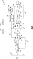
Figure 2 , with continued reference toFigure 1 , afirst water flow 88 is communicated to theinlet 68 of thefirst evaporator 36. Thefirst water flow 88 is heated and exhausted as a preheated water flow indicated at 96. Thepreheated water flow 96 is combined with asecond water flow 90 that is first routed to cool thefirst heat load 64. Accordingly, thesecond water flow 90 is already warmed and is combined with thepreheated water 96 from thefirst evaporator portion 36. Thesecond water flow 90 and thepreheated water flow 96 are combined and communicated through thesecond inlet 70 into the hottersecond evaporator portion 38. - Heat rejection from the
exhaust gas flow 50 into thesecond evaporator section 38 provides for lower core flow temperatures into thefirst evaporator section 36. In this disclosed example, thefirst evaporator portion 36 is spaced apart from the turbine section 28 adistance 94. Thesecond evaporator portion 38 is spaced apart from the turbine section 28 adistance 92 that is less than thefirst distance 94. The different distances correspond to the different operating temperatures of eachevaporator portion - The
exhaust gas flow 50 is first flowed through thesecond evaporator portion 38 where it is cooled by rejecting heat into the combined water flow to generate steam. The cooler gas flow from thesecond evaporator 38 is communicated to thefirst evaporator 36 where it is further cooled to generate a cooledexhaust gas flow 82 that is communicated to acondenser 78 of thewater recovery assembly 40. In thecondenser 78, the cooledexhaust gas flow 82 is further cooled to extract liquid water and is communicated as a liquid/gas flow 84 to awater separator 80. Thewater separator 80 extracts water and expels the remaining portion of the exhaust gas flow as indicated at 86. The water flow from thewater separator 80 is split into thefirst water flow 88 and thesecond water flow 90. - Provision of the lowest temperature water to both the
first evaporator section 36 and the heat loads 64 and integrating the water flows 90 and 96 to receive heat from the highest temperature waste maximizes the waste heat recovery from both the lower temperature heat load and the higher temperature core flow. - The
example evaporator portions - In one disclosed embodiment, a portion of the water flow is provided upstream to the
compressor section 24 for intercooling. An intercooling flow ofwater 76 provides for improved compressor performance. Moreover, although intercooling of thecompressor section 24 is shown and disclosed by way of example, the flow ofwater 76 could be utilized for other engine cooling functions. - Referring to
Figure 3 , another disclosed example engine embodiment is shown and indicated at 25 and includes anintercooling heat exchanger 98 that receives awater flow 90 from theheat load 64. Theintercooler heat exchanger 98 may provide cooling for any heat load on the engine or aircraft, such as a heat load from cooling air passing from one stage of compression to a higher pressure stage of compression. Theintercooler heat exchanger 98 may provide cooling for a cooled cooling air system, a compressor intercooling system, cooling of a lubrication system or any other system or component that operates better when cooled. A combined water flow indicated at 104, includes preheated water from thefirst evaporator 36, from theheat load 64 and from theintercooler heat exchanger 98. The preheating of the combinedwater flow 104 enables a greater amount of steam generation than if all the thermal energy required for transformation was provided only by thesecond evaporator 38. - Referring to
Figure 4 , another disclosed example engine embodiment is shown and indicated at 35 and includes thesecond evaporator 38 disposed betweenturbine sections second evaporator 38 is disposed between the highpressure turbine section 30 and the lowpressure turbine section 32. Theexhaust gas flow 50 communicated to thesecond evaporator portion 38 is therefore much hotter than the gas flow exhausted from the lowpressure turbine section 32. The highertemperature gas flow 50 further improves the generation and superheating temperature of thesteam flow 56. Thefirst evaporator portion 36 is disposed aft and downstream of thelast turbine section 32. - Although the disclosed example embodiment shows the
second evaporator portion 38 disposed between thehigh pressure turbine 30 and thelow pressure turbine 32, thesecond evaporator 38 may be located anywhere within theturbine section 28 upstream of at least one turbine section. Moreover, thefirst evaporator portion 36 may be disposed anywhere aft of a last portion of theturbine section 28. - Accordingly, the disclosed evaporator assemblies provide improved heating and cooling functions by providing separate portions that can be individually tailored to maximize steam generation and exhaust gas cooling.
- Although an example embodiment has been disclosed, a worker of ordinary skill in this art would recognize that certain modifications would come within the scope of this disclosure. For that reason, the following claims should be studied to determine the scope and content of this disclosure.
Claims (15)
- A turbine engine assembly (20; 25; 35) comprising:a core engine including a core flow path where air is compressed in a compressor section (24), communicated to a combustor section (26), mixed with fuel, and ignited to generate an exhaust gas flow (50) that is expanded through a turbine section (28, 30, 32);a condenser assembly (78) arranged along the core flow path to extract water from the exhaust gas flow (50); andan evaporator assembly (34, 36, 38) where thermal energy from the exhaust gas flow (50) is communicated to the water extracted by the condenser assembly (78) to generate a steam flow (56) for injection into the core flow path, the evaporator assembly (34) having a first inlet (68) for a first flow of water (88) and a second inlet (70) for a second flow of water (90) upstream of the first inlet (68), relative to the core flow path.
- The turbine engine assembly (20; 25; 35) as recited in claim 1, wherein a spacing between a last stage of the turbine section (32) and the first inlet (68) is greater than a spacing between the last stage of the turbine section (32) and the second inlet (70).
- The turbine engine assembly (20; 25; 35) as recited in claim 1 or 2, wherein the evaporator assembly (34) includes a first outlet (72) and a second outlet (74), wherein the second outlet (74) is upstream of the first outlet (72) and a flow of water (96) from the first outlet (72) is combined with the second flow of water (90) communicated to the second inlet (70), relative to the core flow path.
- The turbine engine assembly (20; 25; 35) as recited in claim 1, 2 or 3, including at least one heat load (64), upstream of the second inlet (70) relative to a flow of water through the second inlet (70), where the second water flow (90) is preheated before entering the evaporator assembly (34, 36, 38).
- The turbine engine assembly (35) as recited in claim 4, including an intercooler (98), upstream of the second inlet (70) relative to a flow of water through the second inlet (70), where the preheated second water flow (90) is cooled prior to entering the evaporator assembly (34).
- The engine assembly (20; 25; 35) as recited in any preceding claim, configured such that the second flow of water (90) into the evaporator assembly (34) is at a higher temperature than the first inlet flow of water (88) in the evaporator (34).
- The engine assembly (20; 25; 35) as recited in any preceding claim, configured such that the steam temperature exiting the evaporator assembly (34) is between 550 (288 °C) and 1500 F (816 °C).
- The turbine engine assembly (35) as recited in any preceding claim, wherein the evaporator assembly (34) includes a first evaporator portion (38) disposed upstream of a portion of the turbine section (32) and a second evaporator portion (36) disposed downstream of the turbine section (32), relative to the core flow path.
- The turbine engine assembly (35) as recited in claim 8, wherein the turbine section includes a first turbine (30) and a second turbine (32) and the first evaporator portion (38) is disposed between the first turbine (30) and the second turbine (32) and the second evaporator assembly (36) is disposed downstream of the second turbine (32), relative to the core flow path.
- The turbine engine assembly (20; 25; 35) as recited in any preceding claim, wherein the condenser assembly (78) includes a condenser portion, where water from the exhaust gas flow (50) is condensed into a liquid, and a water separator (80) where the liquid is separated from the exhaust gas flow (50).
- The turbine engine assembly (20; 25; 35) as recited in any preceding claim, wherein at least a portion of water extracted by the condenser assembly (78) is communicated to a location upstream of the combustor (26), relative to the core flow path.
- The turbine engine assembly (20; 25; 35) as recited in any preceding claim, wherein at least a portion of the steam flow (56) is injected into the combustor section (26).
- The turbine engine assembly (20; 25; 35) as recited in any preceding claim, including a hydrogen fuel system (42) for suppling hydrogen fuel to the combustor (26) through a fuel flow path (66).
- A method of generating a steam flow (56) in a turbine engine assembly (20; 25; 35), the method comprising:extracting water from an exhaust gas flow (50);communicating a first flow (88) of the extracted water to a first heating circuit (60) of an evaporator (34) exposed to the exhaust gas flow (50);communicating a second flow (90) of the extracted water to a second heating circuit (62) of the evaporator (34) exposed to the exhaust gas flow (50), wherein the second heating circuit (62) is in a hotter portion of the exhaust gas flow (50) than the first heating circuit (60);directing heated water flow from the first heating circuit (60) into the second heating circuit (62); heating the water flow in the second heating circuit (62) to generate a steam flow (56); andcommunicating the generated steam flow (56) to a core flow path of the turbine engine (20; 25; 35),optionally wherein the method further comprises heating the second flow (90) of extracted water with at least one heat load (64) to preheat the second flow (90) prior to entering the evaporator (34).
- The method as recited in claim 14, wherein the first flow (88) in the first heating circuit (60) generates steam and the second heating circuit (62) generates a superheated steam flow (56).
Applications Claiming Priority (2)
| Application Number | Priority Date | Filing Date | Title |
|---|---|---|---|
| US202363441511P | 2023-01-27 | 2023-01-27 | |
| US18/486,362 US12152532B2 (en) | 2023-01-27 | 2023-10-13 | Split evaporator for steam injection turbine engine |
Publications (1)
| Publication Number | Publication Date |
|---|---|
| EP4407164A1 true EP4407164A1 (en) | 2024-07-31 |
Family
ID=89772320
Family Applications (1)
| Application Number | Title | Priority Date | Filing Date |
|---|---|---|---|
| EP24154536.7A Pending EP4407164A1 (en) | 2023-01-27 | 2024-01-29 | Split evaporator for steam injection turbine engine |
Country Status (2)
| Country | Link |
|---|---|
| US (1) | US12152532B2 (en) |
| EP (1) | EP4407164A1 (en) |
Families Citing this family (2)
| Publication number | Priority date | Publication date | Assignee | Title |
|---|---|---|---|---|
| US12338769B2 (en) * | 2023-09-08 | 2025-06-24 | General Electric Company | Turbine engine including a steam system |
| US12421895B2 (en) * | 2024-02-01 | 2025-09-23 | General Electric Company | Turbine engine including a condenser system |
Citations (3)
| Publication number | Priority date | Publication date | Assignee | Title |
|---|---|---|---|---|
| US5628183A (en) * | 1994-10-12 | 1997-05-13 | Rice; Ivan G. | Split stream boiler for combined cycle power plants |
| US20210207500A1 (en) * | 2018-05-22 | 2021-07-08 | MTU Aero Engines AG | Exhaust-gas treatment device, aircraft propulsion system, and method for treating an exhaust-gas stream |
| EP4227513A1 (en) * | 2022-02-11 | 2023-08-16 | Raytheon Technologies Corporation | Turbine engine with mass rejection |
Family Cites Families (6)
| Publication number | Priority date | Publication date | Assignee | Title |
|---|---|---|---|---|
| DE2413507A1 (en) * | 1974-03-20 | 1975-10-02 | Motoren Turbinen Union | GAS TURBINE FOR CRYOGENIC FUEL |
| DE19541914A1 (en) * | 1995-11-10 | 1997-05-15 | Asea Brown Boveri | Cooling air cooler for power plants |
| US5826430A (en) * | 1996-04-23 | 1998-10-27 | Westinghouse Electric Corporation | Fuel heating system used in conjunction with steam cooled combustors and transitions |
| GB9906620D0 (en) * | 1999-03-23 | 1999-05-19 | Rolls Royce Plc | Power generation equipment |
| US8726663B2 (en) * | 2010-01-05 | 2014-05-20 | General Electric Company | Combined cycle system employing phase change material |
| DE102019203595A1 (en) | 2019-03-15 | 2020-09-17 | MTU Aero Engines AG | Aircraft |
-
2023
- 2023-10-13 US US18/486,362 patent/US12152532B2/en active Active
-
2024
- 2024-01-29 EP EP24154536.7A patent/EP4407164A1/en active Pending
Patent Citations (3)
| Publication number | Priority date | Publication date | Assignee | Title |
|---|---|---|---|---|
| US5628183A (en) * | 1994-10-12 | 1997-05-13 | Rice; Ivan G. | Split stream boiler for combined cycle power plants |
| US20210207500A1 (en) * | 2018-05-22 | 2021-07-08 | MTU Aero Engines AG | Exhaust-gas treatment device, aircraft propulsion system, and method for treating an exhaust-gas stream |
| EP4227513A1 (en) * | 2022-02-11 | 2023-08-16 | Raytheon Technologies Corporation | Turbine engine with mass rejection |
Also Published As
| Publication number | Publication date |
|---|---|
| US20240254914A1 (en) | 2024-08-01 |
| US12152532B2 (en) | 2024-11-26 |
Similar Documents
| Publication | Publication Date | Title |
|---|---|---|
| US20210254550A1 (en) | Gas Turbine Energy Supplementing Systems and Heating Systems, and Methods of Making and Using the Same | |
| EP4407164A1 (en) | Split evaporator for steam injection turbine engine | |
| EP4414544A1 (en) | Increased water heat absorption capacity for steam injected turbine engine | |
| US12442330B2 (en) | Condenser for hydrogen steam injected turbine engine | |
| US12215622B1 (en) | Partial exhaust condensation intercooling | |
| EP3387243A1 (en) | Inverted brayton cycle heat engine | |
| US12180893B2 (en) | Hydrogen steam injected turbine engine with turboexpander heat recovery | |
| US12092022B2 (en) | Forward mounted hydrogen steam injected and inter-cooled turbine engine with octopus ducting | |
| EP4520934A1 (en) | Partial exhaust gas condensation with inverse brayton control | |
| EP4517059A1 (en) | Partial exhaust gas augmented condensation | |
| US10683804B2 (en) | System for recovering exhaust gas energy | |
| US20240360788A1 (en) | Partial exhaust condensation with cryogenic assisted bottoming cycle | |
| EP4411121A1 (en) | Turbine engine bottoming cycle heat exchanger bypass | |
| EP4279719B1 (en) | Hydrogen steam injected turbine engine with cooled cooling air | |
| US11927132B1 (en) | Water separator for hydrogen steam injected turbine engine | |
| US12473858B2 (en) | Partial exhaust bottoming cycle | |
| US20240360791A1 (en) | Cryo-assisted bottoming cycle heat source sequencing | |
| US12510023B1 (en) | Fan case mounted evaporator for aircraft turbine engine | |
| EP4678893A1 (en) | Cryo-assisted bottoming cycle heat source sequencing | |
| US20260063068A1 (en) | Evaporator system within an inner fixed structure of an aircraft propulsion system | |
| EP4656857A2 (en) | Axial flow angled condenser arrangement for an aircraft propulsion system |
Legal Events
| Date | Code | Title | Description |
|---|---|---|---|
| PUAI | Public reference made under article 153(3) epc to a published international application that has entered the european phase |
Free format text: ORIGINAL CODE: 0009012 |
|
| STAA | Information on the status of an ep patent application or granted ep patent |
Free format text: STATUS: THE APPLICATION HAS BEEN PUBLISHED |
|
| AK | Designated contracting states |
Kind code of ref document: A1 Designated state(s): AL AT BE BG CH CY CZ DE DK EE ES FI FR GB GR HR HU IE IS IT LI LT LU LV MC ME MK MT NL NO PL PT RO RS SE SI SK SM TR |
|
| STAA | Information on the status of an ep patent application or granted ep patent |
Free format text: STATUS: REQUEST FOR EXAMINATION WAS MADE |
|
| 17P | Request for examination filed |
Effective date: 20250131 |