EP4407147A1 - Process of brazing a cover to an open body for a hollow vane assembly, hollow vane assembly and process for joining a cover to an open body - Google Patents
Process of brazing a cover to an open body for a hollow vane assembly, hollow vane assembly and process for joining a cover to an open body Download PDFInfo
- Publication number
- EP4407147A1 EP4407147A1 EP24153710.9A EP24153710A EP4407147A1 EP 4407147 A1 EP4407147 A1 EP 4407147A1 EP 24153710 A EP24153710 A EP 24153710A EP 4407147 A1 EP4407147 A1 EP 4407147A1
- Authority
- EP
- European Patent Office
- Prior art keywords
- open body
- cover
- forming
- interior
- support structure
- Prior art date
- Legal status (The legal status is an assumption and is not a legal conclusion. Google has not performed a legal analysis and makes no representation as to the accuracy of the status listed.)
- Pending
Links
- 238000000034 method Methods 0.000 title claims abstract description 33
- 230000008569 process Effects 0.000 title claims abstract description 31
- 238000005219 brazing Methods 0.000 title claims abstract description 20
- 238000005304 joining Methods 0.000 title claims abstract description 4
- 230000009977 dual effect Effects 0.000 claims abstract description 6
- 239000000463 material Substances 0.000 claims description 9
- 238000001816 cooling Methods 0.000 claims description 6
- 239000012809 cooling fluid Substances 0.000 claims description 5
- 238000013461 design Methods 0.000 claims description 5
- 230000008901 benefit Effects 0.000 description 11
- 238000004519 manufacturing process Methods 0.000 description 7
- 238000005266 casting Methods 0.000 description 5
- 239000000446 fuel Substances 0.000 description 4
- 239000012530 fluid Substances 0.000 description 3
- 238000007689 inspection Methods 0.000 description 3
- 238000003754 machining Methods 0.000 description 3
- 230000009467 reduction Effects 0.000 description 3
- 230000003068 static effect Effects 0.000 description 3
- PXHVJJICTQNCMI-UHFFFAOYSA-N Nickel Chemical compound [Ni] PXHVJJICTQNCMI-UHFFFAOYSA-N 0.000 description 2
- 238000010438 heat treatment Methods 0.000 description 2
- 239000000203 mixture Substances 0.000 description 2
- 238000012986 modification Methods 0.000 description 2
- 230000004048 modification Effects 0.000 description 2
- 230000004044 response Effects 0.000 description 2
- 239000000654 additive Substances 0.000 description 1
- 230000000996 additive effect Effects 0.000 description 1
- 230000015572 biosynthetic process Effects 0.000 description 1
- 230000008859 change Effects 0.000 description 1
- 229910017052 cobalt Inorganic materials 0.000 description 1
- 239000010941 cobalt Substances 0.000 description 1
- GUTLYIVDDKVIGB-UHFFFAOYSA-N cobalt atom Chemical compound [Co] GUTLYIVDDKVIGB-UHFFFAOYSA-N 0.000 description 1
- 238000004891 communication Methods 0.000 description 1
- 230000006835 compression Effects 0.000 description 1
- 238000007906 compression Methods 0.000 description 1
- 238000012937 correction Methods 0.000 description 1
- 238000009792 diffusion process Methods 0.000 description 1
- 230000000694 effects Effects 0.000 description 1
- 230000007246 mechanism Effects 0.000 description 1
- 239000002184 metal Substances 0.000 description 1
- 229910052751 metal Inorganic materials 0.000 description 1
- 229910001092 metal group alloy Inorganic materials 0.000 description 1
- 229910052759 nickel Inorganic materials 0.000 description 1
- 238000012805 post-processing Methods 0.000 description 1
- 229910000601 superalloy Inorganic materials 0.000 description 1
- 230000000007 visual effect Effects 0.000 description 1
Images


Classifications
-
- F—MECHANICAL ENGINEERING; LIGHTING; HEATING; WEAPONS; BLASTING
- F01—MACHINES OR ENGINES IN GENERAL; ENGINE PLANTS IN GENERAL; STEAM ENGINES
- F01D—NON-POSITIVE DISPLACEMENT MACHINES OR ENGINES, e.g. STEAM TURBINES
- F01D9/00—Stators
- F01D9/06—Fluid supply conduits to nozzles or the like
- F01D9/065—Fluid supply or removal conduits traversing the working fluid flow, e.g. for lubrication-, cooling-, or sealing fluids
-
- F—MECHANICAL ENGINEERING; LIGHTING; HEATING; WEAPONS; BLASTING
- F01—MACHINES OR ENGINES IN GENERAL; ENGINE PLANTS IN GENERAL; STEAM ENGINES
- F01D—NON-POSITIVE DISPLACEMENT MACHINES OR ENGINES, e.g. STEAM TURBINES
- F01D5/00—Blades; Blade-carrying members; Heating, heat-insulating, cooling or antivibration means on the blades or the members
- F01D5/12—Blades
- F01D5/14—Form or construction
- F01D5/16—Form or construction for counteracting blade vibration
-
- B—PERFORMING OPERATIONS; TRANSPORTING
- B23—MACHINE TOOLS; METAL-WORKING NOT OTHERWISE PROVIDED FOR
- B23K—SOLDERING OR UNSOLDERING; WELDING; CLADDING OR PLATING BY SOLDERING OR WELDING; CUTTING BY APPLYING HEAT LOCALLY, e.g. FLAME CUTTING; WORKING BY LASER BEAM
- B23K1/00—Soldering, e.g. brazing, or unsoldering
- B23K1/0008—Soldering, e.g. brazing, or unsoldering specially adapted for particular articles or work
- B23K1/0018—Brazing of turbine parts
-
- B—PERFORMING OPERATIONS; TRANSPORTING
- B23—MACHINE TOOLS; METAL-WORKING NOT OTHERWISE PROVIDED FOR
- B23P—METAL-WORKING NOT OTHERWISE PROVIDED FOR; COMBINED OPERATIONS; UNIVERSAL MACHINE TOOLS
- B23P15/00—Making specific metal objects by operations not covered by a single other subclass or a group in this subclass
- B23P15/04—Making specific metal objects by operations not covered by a single other subclass or a group in this subclass turbine or like blades from several pieces
-
- F—MECHANICAL ENGINEERING; LIGHTING; HEATING; WEAPONS; BLASTING
- F01—MACHINES OR ENGINES IN GENERAL; ENGINE PLANTS IN GENERAL; STEAM ENGINES
- F01D—NON-POSITIVE DISPLACEMENT MACHINES OR ENGINES, e.g. STEAM TURBINES
- F01D17/00—Regulating or controlling by varying flow
- F01D17/10—Final actuators
- F01D17/12—Final actuators arranged in stator parts
- F01D17/14—Final actuators arranged in stator parts varying effective cross-sectional area of nozzles or guide conduits
- F01D17/16—Final actuators arranged in stator parts varying effective cross-sectional area of nozzles or guide conduits by means of nozzle vanes
- F01D17/162—Final actuators arranged in stator parts varying effective cross-sectional area of nozzles or guide conduits by means of nozzle vanes for axial flow, i.e. the vanes turning around axes which are essentially perpendicular to the rotor centre line
-
- F—MECHANICAL ENGINEERING; LIGHTING; HEATING; WEAPONS; BLASTING
- F01—MACHINES OR ENGINES IN GENERAL; ENGINE PLANTS IN GENERAL; STEAM ENGINES
- F01D—NON-POSITIVE DISPLACEMENT MACHINES OR ENGINES, e.g. STEAM TURBINES
- F01D25/00—Component parts, details, or accessories, not provided for in, or of interest apart from, other groups
- F01D25/08—Cooling; Heating; Heat-insulation
- F01D25/12—Cooling
-
- F—MECHANICAL ENGINEERING; LIGHTING; HEATING; WEAPONS; BLASTING
- F01—MACHINES OR ENGINES IN GENERAL; ENGINE PLANTS IN GENERAL; STEAM ENGINES
- F01D—NON-POSITIVE DISPLACEMENT MACHINES OR ENGINES, e.g. STEAM TURBINES
- F01D5/00—Blades; Blade-carrying members; Heating, heat-insulating, cooling or antivibration means on the blades or the members
- F01D5/12—Blades
- F01D5/14—Form or construction
- F01D5/147—Construction, i.e. structural features, e.g. of weight-saving hollow blades
-
- F—MECHANICAL ENGINEERING; LIGHTING; HEATING; WEAPONS; BLASTING
- F01—MACHINES OR ENGINES IN GENERAL; ENGINE PLANTS IN GENERAL; STEAM ENGINES
- F01D—NON-POSITIVE DISPLACEMENT MACHINES OR ENGINES, e.g. STEAM TURBINES
- F01D9/00—Stators
- F01D9/02—Nozzles; Nozzle boxes; Stator blades; Guide conduits, e.g. individual nozzles
- F01D9/04—Nozzles; Nozzle boxes; Stator blades; Guide conduits, e.g. individual nozzles forming ring or sector
- F01D9/041—Nozzles; Nozzle boxes; Stator blades; Guide conduits, e.g. individual nozzles forming ring or sector using blades
-
- F—MECHANICAL ENGINEERING; LIGHTING; HEATING; WEAPONS; BLASTING
- F05—INDEXING SCHEMES RELATING TO ENGINES OR PUMPS IN VARIOUS SUBCLASSES OF CLASSES F01-F04
- F05D—INDEXING SCHEME FOR ASPECTS RELATING TO NON-POSITIVE-DISPLACEMENT MACHINES OR ENGINES, GAS-TURBINES OR JET-PROPULSION PLANTS
- F05D2220/00—Application
- F05D2220/30—Application in turbines
- F05D2220/32—Application in turbines in gas turbines
-
- F—MECHANICAL ENGINEERING; LIGHTING; HEATING; WEAPONS; BLASTING
- F05—INDEXING SCHEMES RELATING TO ENGINES OR PUMPS IN VARIOUS SUBCLASSES OF CLASSES F01-F04
- F05D—INDEXING SCHEME FOR ASPECTS RELATING TO NON-POSITIVE-DISPLACEMENT MACHINES OR ENGINES, GAS-TURBINES OR JET-PROPULSION PLANTS
- F05D2230/00—Manufacture
- F05D2230/20—Manufacture essentially without removing material
- F05D2230/21—Manufacture essentially without removing material by casting
- F05D2230/211—Manufacture essentially without removing material by casting by precision casting, e.g. microfusing or investment casting
-
- F—MECHANICAL ENGINEERING; LIGHTING; HEATING; WEAPONS; BLASTING
- F05—INDEXING SCHEMES RELATING TO ENGINES OR PUMPS IN VARIOUS SUBCLASSES OF CLASSES F01-F04
- F05D—INDEXING SCHEME FOR ASPECTS RELATING TO NON-POSITIVE-DISPLACEMENT MACHINES OR ENGINES, GAS-TURBINES OR JET-PROPULSION PLANTS
- F05D2230/00—Manufacture
- F05D2230/20—Manufacture essentially without removing material
- F05D2230/23—Manufacture essentially without removing material by permanently joining parts together
- F05D2230/232—Manufacture essentially without removing material by permanently joining parts together by welding
- F05D2230/237—Brazing
-
- F—MECHANICAL ENGINEERING; LIGHTING; HEATING; WEAPONS; BLASTING
- F05—INDEXING SCHEMES RELATING TO ENGINES OR PUMPS IN VARIOUS SUBCLASSES OF CLASSES F01-F04
- F05D—INDEXING SCHEME FOR ASPECTS RELATING TO NON-POSITIVE-DISPLACEMENT MACHINES OR ENGINES, GAS-TURBINES OR JET-PROPULSION PLANTS
- F05D2230/00—Manufacture
- F05D2230/50—Building or constructing in particular ways
- F05D2230/54—Building or constructing in particular ways by sheet metal manufacturing
-
- F—MECHANICAL ENGINEERING; LIGHTING; HEATING; WEAPONS; BLASTING
- F05—INDEXING SCHEMES RELATING TO ENGINES OR PUMPS IN VARIOUS SUBCLASSES OF CLASSES F01-F04
- F05D—INDEXING SCHEME FOR ASPECTS RELATING TO NON-POSITIVE-DISPLACEMENT MACHINES OR ENGINES, GAS-TURBINES OR JET-PROPULSION PLANTS
- F05D2240/00—Components
- F05D2240/10—Stators
- F05D2240/12—Fluid guiding means, e.g. vanes
-
- F—MECHANICAL ENGINEERING; LIGHTING; HEATING; WEAPONS; BLASTING
- F05—INDEXING SCHEMES RELATING TO ENGINES OR PUMPS IN VARIOUS SUBCLASSES OF CLASSES F01-F04
- F05D—INDEXING SCHEME FOR ASPECTS RELATING TO NON-POSITIVE-DISPLACEMENT MACHINES OR ENGINES, GAS-TURBINES OR JET-PROPULSION PLANTS
- F05D2260/00—Function
- F05D2260/20—Heat transfer, e.g. cooling
- F05D2260/213—Heat transfer, e.g. cooling by the provision of a heat exchanger within the cooling circuit
Definitions
- the present disclosure is directed to a hollow vane with an open body and a cover joined via brazing to form a desired vane geometry.
- Hollow vanes are typically utilized to enable air, either hot or cold, to flow through the part to achieve a desired thermal effect.
- hollow vanes have been manufactured by casting the external airfoil shape with cores located internally within the mold. This method results in a hollow cavity within the cast part, however, castings, from both a process capability and supplier willingness perspectives, are not capable of meeting the dimensional and material requirements as demanded by the engine operating environment.
- a process of brazing a cover to an open body for a hollow vane assembly comprising forming an open body, the open body including an interior forming at least one cover support structure in said open body proximate the interior; forming a cover, the cover being configured to attach to the open body to form at least one flow passage; and brazing the cover to the open body.
- Particular embodiments may include at least one, or a plurality of, the following optional features. These features may be provided separately from each other, or in combination with each other, unless specified otherwise.
- a further embodiment of any of the foregoing embodiments may additionally and/or alternatively include the process further comprising forming the at least one flow passage between the at least one cover support structure and an interior wall of the open body.
- a further embodiment of any of the foregoing embodiments may additionally and/or alternatively include the at least one flow passage is configured as multiple cooling channels that allow for cooling fluid to flow through the interior.
- a further embodiment of any of the foregoing embodiments may additionally and/or alternatively include the process further comprising forming an airfoil from the combination of the open body brazed together with the cover.
- a further embodiment of any of the foregoing embodiments may additionally and/or alternatively include the process further comprising forming a dual walled structure having contoured surfaces.
- a further embodiment of any of the foregoing embodiments may additionally and/or alternatively include the open body comprises a single piece design.
- a further embodiment of any of the foregoing embodiments may additionally and/or alternatively include at least one of the open body and the cover comprises a rigid material.
- a hollow vane assembly comprising an open body including an interior; at least one cover support structure formed in said open body proximate the interior; and a cover brazed to the open body to form at least one flow passage.
- Particular embodiments may include at least one, or a plurality of, the following optional features. These features may be provided separately from each other, or in combination with each other, unless specified otherwise.
- a further embodiment of any of the foregoing embodiments may additionally and/or alternatively include the at least one flow passage is formed between the at least one cover support structure and an interior wall of the open body.
- a further embodiment of any of the foregoing embodiments may additionally and/or alternatively include an airfoil is formed from the combination of the open body brazed together with the cover.
- a further embodiment of any of the foregoing embodiments may additionally and/or alternatively include a dual walled structure having contoured surfaces is formed by the open body brazed together with the cover.
- a further embodiment of any of the foregoing embodiments may additionally and/or alternatively include the open body comprises a single piece design.
- a further embodiment of any of the foregoing embodiments may additionally and/or alternatively include at least one of the open body and the cover comprises a rigid material.
- a process for joining a cover to an open body comprising forming an open body, the open body includes a leading edge opposite a trailing edge, the open body includes a pressure side and suction side opposite the pressure side, the open body including an interior forming at least one cover support structure in said open body proximate the interior; forming a cover, the cover being configured to couple with the open body proximate the pressure side to form at least one flow passage; and brazing the cover to the open body.
- Particular embodiments may include at least one, or a plurality of, the following optional features. These features may be provided separately from each other, or in combination with each other, unless specified otherwise.
- a further embodiment of any of the foregoing embodiments may additionally and/or alternatively include the process further comprising forming structural joints along the union between the cover support structure and the cover.
- a further embodiment of any of the foregoing embodiments may additionally and/or alternatively include the process further comprising forming a non-structural joint between the cover and the open body proximate the leading edge.
- a further embodiment of any of the foregoing embodiments may additionally and/or alternatively include the process further comprising forming the at least one flow passage between the at least one cover support structure and an interior wall of the open body.
- a further embodiment of any of the foregoing embodiments may additionally and/or alternatively include the at least one flow passage is configured as multiple cooling channels that allow for cooling fluid to flow through the interior.
- a further embodiment of any of the foregoing embodiments may additionally and/or alternatively include the process further comprising forming an airfoil from the combination of the open body brazed together with the cover.
- a further embodiment of any of the foregoing embodiments may additionally and/or alternatively include the at least one cover support structure comprises raised surface features of the open body that extend from the open body distally.
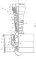
- FIG. 1 schematically illustrates a gas turbine engine 20.
- the gas turbine engine 20 is disclosed herein as a two-spool turbofan that generally incorporates a fan section 22, a compressor section 24, a combustor section 26 and a turbine section 28.
- the fan section 22 may include a single-stage fan 42 having a plurality of fan blades 43.
- the fan blades 43 may have a fixed stagger angle or may have a variable pitch to direct incoming airflow from an engine inlet.
- the fan 42 drives air along a bypass flow path B in a bypass duct 13 defined within a housing 15 such as a fan case or nacelle, and also drives air along a core flow path C for compression and communication into the combustor section 26 then expansion through the turbine section 28.
- a splitter 29 aft of the fan 42 divides the air between the bypass flow path B and the core flow path C.
- the housing 15 may surround the fan 42 to establish an outer diameter of the bypass duct 13.
- the splitter 29 may establish an inner diameter of the bypass duct 13.
- the exemplary engine 20 generally includes a low speed spool 30 and a high speed spool 32 mounted for rotation about an engine central longitudinal axis A relative to an engine static structure 36 via several bearing systems 38. It should be understood that various bearing systems 38 at various locations may alternatively or additionally be provided, and the location of bearing systems 38 may be varied as appropriate to the application.
- the low speed spool 30 generally includes an inner shaft 40 that interconnects, a first (or low) pressure compressor 44 and a first (or low) pressure turbine 46.
- the inner shaft 40 is connected to the fan 42 through a speed change mechanism, which in the exemplary gas turbine engine 20 is illustrated as a geared architecture 48 to drive the fan 42 at a lower speed than the low speed spool 30.
- the inner shaft 40 may interconnect the low pressure compressor 44 and low pressure turbine 46 such that the low pressure compressor 44 and low pressure turbine 46 are rotatable at a common speed and in a common direction.
- the low pressure turbine 46 drives both the fan 42 and low pressure compressor 44 through the geared architecture 48 such that the fan 42 and low pressure compressor 44 are rotatable at a common speed.
- the high speed spool 32 includes an outer shaft 50 that interconnects a second (or high) pressure compressor 52 and a second (or high) pressure turbine 54.
- a combustor 56 is arranged in the exemplary gas turbine 20 between the high pressure compressor 52 and the high pressure turbine 54.
- a mid-turbine frame 57 of the engine static structure 36 may be arranged generally between the high pressure turbine 54 and the low pressure turbine 46.
- the mid-turbine frame 57 further supports bearing systems 38 in the turbine section 28.
- the inner shaft 40 and the outer shaft 50 are concentric and rotate via bearing systems 38 about the engine central longitudinal axis A which is collinear with their longitudinal axes.
- Airflow in the core flow path C is compressed by the low pressure compressor 44 then the high pressure compressor 52, mixed and burned with fuel in the combustor 56, then expanded through the high pressure turbine 54 and low pressure turbine 46.
- the mid-turbine frame 57 includes airfoils 59 which are in the core flow path C.
- the turbines 46, 54 rotationally drive the respective low speed spool 30 and high speed spool 32 in response to the expansion.
- gear system 48 may be located aft of the low pressure compressor, or aft of the combustor section 26 or even aft of turbine section 28, and fan 42 may be positioned forward or aft of the location of gear system 48.
- the low pressure compressor 44, high pressure compressor 52, high pressure turbine 54 and low pressure turbine 46 each include one or more stages having a row of rotatable airfoils. Each stage may include a row of static vanes adjacent the rotatable airfoils.
- the rotatable airfoils and vanes are schematically indicated at 47 and 49.
- the engine 20 may be a high-bypass geared aircraft engine.
- the bypass ratio can be greater than or equal to 10.0 and less than or equal to about 18.0, or more narrowly can be less than or equal to 16.0.
- the geared architecture 48 may be an epicyclic gear train, such as a planetary gear system or a star gear system.
- the epicyclic gear train may include a sun gear, a ring gear, a plurality of intermediate gears meshing with the sun gear and ring gear, and a carrier that supports the intermediate gears.
- the sun gear may provide an input to the gear train.
- the ring gear (e.g., star gear system) or carrier (e.g., planetary gear system) may provide an output of the gear train to drive the fan 42.
- a gear reduction ratio may be greater than or equal to 2.3, or more narrowly greater than or equal to 3.0, and in some embodiments the gear reduction ratio is greater than or equal to 3.4.
- the gear reduction ratio may be less than or equal to 4.0.
- the fan diameter is significantly larger than that of the low pressure compressor 44.
- the low pressure turbine 46 can have a pressure ratio that is greater than or equal to 8.0 and in some embodiments is greater than or equal to 10.0.
- the low pressure turbine pressure ratio can be less than or equal to 13.0, or more narrowly less than or equal to 12.0.
- Low pressure turbine 46 pressure ratio is pressure measured prior to an inlet of low pressure turbine 46 as related to the pressure at the outlet of the low pressure turbine 46 prior to an exhaust nozzle. It should be understood, however, that the above parameters are only exemplary of one embodiment of a geared architecture engine and that the present invention is applicable to other gas turbine engines including direct drive turbofans. All of these parameters are measured at the cruise condition described below.
- the fan section 22 of the engine 20 is designed for a particular flight condition -- typically cruise at about 0.8 Mach and about 35,000 feet (10,668 meters).
- the flight condition of 0.8 Mach and 35,000 ft (10,668 meters), with the engine at its best fuel consumption - also known as "bucket cruise Thrust Specific Fuel Consumption ( ⁇ TSFC')" - is the industry standard parameter of pounds-mass per hour lbm/hr of fuel flow rate being burned divided by pounds-force lbf of thrust the engine produces at that minimum point.
- ⁇ TSFC' Thrust Specific Fuel Consumption
- Low fan pressure ratio is the pressure ratio across the fan blade 43 alone, without a Fan Exit Guide Vane (“FEGV”) system. A distance is established in a radial direction between the inner and outer diameters of the bypass duct 13 at an axial position corresponding to a leading edge of the splitter 29 relative to the engine central longitudinal axis A.
- the low fan pressure ratio is a spanwise average of the pressure ratios measured across the fan blade 43 alone over radial positions corresponding to the distance.
- the low fan pressure ratio can be less than or equal to 1.45, or more narrowly greater than or equal to 1.25, such as between 1.30 and 1.40.
- Low corrected fan tip speed is the actual fan tip speed in ft/sec divided by an industry standard temperature correction of [(Tram °R) / (518.7 °R)] 0.5 .
- the "low corrected fan tip speed” can be less than or equal to 1150.0 ft / second (350.5 meters/second), and greater than or equal to 1000.0 ft / second (304.8 meters/second).
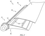
- the hollow-vane assembly 60 includes an open body 62 that can be a single piece design, being completely integral or monolithic.
- the two piece hollow-vane assembly 60 includes a cover 64 that is attachable to the open body 62.
- the open body 62 includes cover support structure(s) 66.
- the open body 62 and cover 64 are combined to form an airfoil 68 of a vane 70 when brazed together.
- the hollow-vane assembly 60 can also be configured as other dual walled structures having contoured surfaces, such as a turbine blade.
- the hollow-vane assembly 60 can include a three dimensionally contoured shape.
- the three dimensional contoured surface can refer to a surface defined by an X, Y, and Z axis.
- the three dimensional contoured surface can vary from point to point to include surface variation of X, Y and Z coordinates.
- the vane assembly 60 is shown with representative fluid flow passages 72 with flow arrows 74.
- the flow arrows 74 show an exemplary cooling/heating fluid 76 flow through the fluid flow passages 72 at the interior 78 formed by the open body 62 and cover 64.
- the flow passages 72 can be configured as multiple cooling channels 72 that allow for cooling fluid 76 to flow through the interior 78.
- the open body 62 and cover 64 can be constructed from rigid materials, such as a metal alloy and in alternative embodiments, from heat resistant super alloy composition, nickel-based, or cobalt based compositions.
- the open body 62 and cover 64 can be made of the same material or different materials.
- the open body 62 can be formed from a casting, for example.
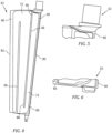
- the open body 62 can include a leading edge 80 opposite a trailing edge 82, a pressure side 86 and suction side 84 opposite the pressure side 86 ( Fig. 2 ).
- the open body 62 including the cover support structures 66 allow for the formation of the flow passages 72.
- the cover support structure 66 can form an interior wall 88.
- the cover support structure 66 can be raised surface features of the open body 62.
- the cover support structure 66 can extend from the open body 62 distally.
- the cover support structure 66 can form parts of the flow passages 72 along with the cover 64 and open body 62.
- the open body 62 with integral cover support structure(s) 66 can be manufactured via a manufacturing process that supports the geometric and material capability needs of the vane 60. Potential manufacturing options for the open body 62 can include casting, additive manufacturing, or conventional machining.
- the cover 64 can be fabricated.
- the cover 64 can be formed to the desired geometry via conventional metal forming methods like stamping, deep drawing, or hydroforming, and machining via multi-axis CNC.
- post processing of all part surfaces may be performed on the cover 64 to achieve the desired metallurgical properties.
- the cover 64 can be permanently joined to the open body 62 via brazing. Any subsequent heat treatment, final finishing, inspections, etc. can follow the brazing.
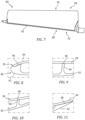
- exemplary structural brazing joints 90 are shown in greater detail.
- the geometry of the structural brazing joints 90 is dictated by the location along the vane assembly 60.
- the brazing joint 90 is located proximate the leading edge 80.
- Fig. 7 illustrates the leading edge 80 with a non-structural seam 92 that can be filled and polished flush for aero considerations.
- the brazing joint 90 is with the cover support structure 66 coupled to the cover 64.
- Fig. 11 shows the brazing joint 90 proximate the trailing edge 82 where the cover 64 and open body 62 join together.
- the process 100 can include the step 102 of forming the open body 62.
- the next step 104 can include forming the cover support structure 66 in the open body 62.
- the next step 106 can include forming the cover 64.
- the next step 108 can include brazing the cover 64 to the open body 62.
- the cover support structure 66 can be coupled to the cover 64 by brazing.
- a technical advantage of the disclosed hollow vane assembly includes the selection of a manufacturing method that meets the geometric requirements of the hardware while reducing the metallurgical shortfalls imposed by when casting hollow vanes.
- Another technical advantage of the disclosed hollow vane assembly includes direct machining access within the internal passageways of the vane.
- Another technical advantage of the disclosed hollow vane assembly includes not being restricted to castable features or geometry that allows for diffusion bonding.
- Another technical advantage of the disclosed hollow vane assembly includes capacity to optimize ice protection air flow.
- Another technical advantage of the disclosed hollow vane assembly includes capacity to optimize the geometry for strength/weight.
- Another technical advantage of the disclosed hollow vane assembly includes capacity to alter the internal structure.
- Another technical advantage of the disclosed hollow vane assembly includes capacity to modify the modal response of the airfoil.
- Another technical advantage of the disclosed hollow vane assembly includes the capacity to modify the structural behavior of the airfoil at different operating points of the engine.
- Another technical advantage of the disclosed hollow vane assembly includes the capacity to optimize the airfoil structure for stresses at different engine operating points.
- Another technical advantage of the disclosed hollow vane assembly includes the ability to perform low-cost visual surface inspections of the open body and coverplate for voids or surface flaws, such as fluorescent penetrant inspection (FPI), before the pieces are brazed together.
- FPI fluorescent penetrant inspection
Landscapes
- Engineering & Computer Science (AREA)
- Mechanical Engineering (AREA)
- General Engineering & Computer Science (AREA)
- Physics & Mathematics (AREA)
- Fluid Mechanics (AREA)
- Architecture (AREA)
- Turbine Rotor Nozzle Sealing (AREA)
Abstract
A process of brazing a cover (64) to an open body (62) for a hollow vane assembly (60) comprises forming an open body, the open body including an interior (78), forming at least one cover support structure (66) in said open body proximate the interior, forming a cover (64), the cover being configured to attach to the open body to form at least one flow passage and brazing the cover to the open body. The hollow vane assembly comprises an open body including an interior. At least one cover support structure is formed in said open body proximate the interior. A cover is brazed to the open body to form at least one flow passage. The at least one flow passage is formed between the at least one cover support structure and an interior wall of the open body. An airfoil is formed from the combination of the open body brazed together with the cover. A dual walled structure having contoured surfaces is formed by the open body brazed together with the cover. A process for joining a cover to an open body comprises forming an open body, the open body including a leading edge (80) opposite a trailing edge (82), the open body including a pressure side (86) and a suction side (84) opposite the pressure side, the open body including an interior (78), forming at least one cover support structure in said open body proximate the interior, forming a cover, the cover being configured to couple with the open body proximate the pressure side to form at least one flow passage and brazing the cover to the open body.
Description
- The present disclosure is directed to a hollow vane with an open body and a cover joined via brazing to form a desired vane geometry.
- Hollow vanes are typically utilized to enable air, either hot or cold, to flow through the part to achieve a desired thermal effect. Historically, hollow vanes have been manufactured by casting the external airfoil shape with cores located internally within the mold. This method results in a hollow cavity within the cast part, however, castings, from both a process capability and supplier willingness perspectives, are not capable of meeting the dimensional and material requirements as demanded by the engine operating environment.
- In accordance with the present disclosure, there is provided a process of brazing a cover to an open body for a hollow vane assembly comprising forming an open body, the open body including an interior forming at least one cover support structure in said open body proximate the interior; forming a cover, the cover being configured to attach to the open body to form at least one flow passage; and brazing the cover to the open body.
- Particular embodiments may include at least one, or a plurality of, the following optional features. These features may be provided separately from each other, or in combination with each other, unless specified otherwise.
- A further embodiment of any of the foregoing embodiments may additionally and/or alternatively include the process further comprising forming the at least one flow passage between the at least one cover support structure and an interior wall of the open body.
- A further embodiment of any of the foregoing embodiments may additionally and/or alternatively include the at least one flow passage is configured as multiple cooling channels that allow for cooling fluid to flow through the interior.
- A further embodiment of any of the foregoing embodiments may additionally and/or alternatively include the process further comprising forming an airfoil from the combination of the open body brazed together with the cover.
- A further embodiment of any of the foregoing embodiments may additionally and/or alternatively include the process further comprising forming a dual walled structure having contoured surfaces.
- A further embodiment of any of the foregoing embodiments may additionally and/or alternatively include the open body comprises a single piece design.
- A further embodiment of any of the foregoing embodiments may additionally and/or alternatively include at least one of the open body and the cover comprises a rigid material.
- In accordance with the present disclosure, there is provided a hollow vane assembly comprising an open body including an interior; at least one cover support structure formed in said open body proximate the interior; and a cover brazed to the open body to form at least one flow passage.
- Particular embodiments may include at least one, or a plurality of, the following optional features. These features may be provided separately from each other, or in combination with each other, unless specified otherwise.
- A further embodiment of any of the foregoing embodiments may additionally and/or alternatively include the at least one flow passage is formed between the at least one cover support structure and an interior wall of the open body.
- A further embodiment of any of the foregoing embodiments may additionally and/or alternatively include an airfoil is formed from the combination of the open body brazed together with the cover.
- A further embodiment of any of the foregoing embodiments may additionally and/or alternatively include a dual walled structure having contoured surfaces is formed by the open body brazed together with the cover.
- A further embodiment of any of the foregoing embodiments may additionally and/or alternatively include the open body comprises a single piece design.
- A further embodiment of any of the foregoing embodiments may additionally and/or alternatively include at least one of the open body and the cover comprises a rigid material.
- In accordance with the present disclosure, there is provided a process for joining a cover to an open body comprising forming an open body, the open body includes a leading edge opposite a trailing edge, the open body includes a pressure side and suction side opposite the pressure side, the open body including an interior forming at least one cover support structure in said open body proximate the interior; forming a cover, the cover being configured to couple with the open body proximate the pressure side to form at least one flow passage; and brazing the cover to the open body.
- Particular embodiments may include at least one, or a plurality of, the following optional features. These features may be provided separately from each other, or in combination with each other, unless specified otherwise.
- A further embodiment of any of the foregoing embodiments may additionally and/or alternatively include the process further comprising forming structural joints along the union between the cover support structure and the cover.
- A further embodiment of any of the foregoing embodiments may additionally and/or alternatively include the process further comprising forming a non-structural joint between the cover and the open body proximate the leading edge.
- A further embodiment of any of the foregoing embodiments may additionally and/or alternatively include the process further comprising forming the at least one flow passage between the at least one cover support structure and an interior wall of the open body.
- A further embodiment of any of the foregoing embodiments may additionally and/or alternatively include the at least one flow passage is configured as multiple cooling channels that allow for cooling fluid to flow through the interior.
- A further embodiment of any of the foregoing embodiments may additionally and/or alternatively include the process further comprising forming an airfoil from the combination of the open body brazed together with the cover.
- A further embodiment of any of the foregoing embodiments may additionally and/or alternatively include the at least one cover support structure comprises raised surface features of the open body that extend from the open body distally.
- Other details of the hollow vane assembly are set forth in the following detailed description and the accompanying drawings wherein like reference numerals depict like elements.
-
Fig. 1 is a cross section view of an exemplary gas turbine engine. -
Fig. 2 is a schematic representation of an exemplary vane assembly. -
Fig. 3 is a schematic representation of the exemplary vane assembly ofFig. 2 . -
Fig. 4 is a schematic representation of an exemplary vane body. -
Fig. 5 is a schematic representation of a portion of the exemplary vane body ofFig. 4 . -
Fig. 6 is a schematic representation of a portion of the exemplary vane body ofFig. 4 . -
Fig. 7 is a schematic representation of an exemplary vane body. -
Fig. 8 is a schematic cross section of a brazed joint. -
Fig. 9 is a schematic cross section of a brazed joint. -
Fig. 10 is a schematic cross section of a brazed joint. -
Fig. 11 is a schematic cross section of a brazed joint. -
Fig. 12 is an exemplary process map. -
Figure 1 schematically illustrates agas turbine engine 20. Thegas turbine engine 20 is disclosed herein as a two-spool turbofan that generally incorporates afan section 22, acompressor section 24, acombustor section 26 and aturbine section 28. Thefan section 22 may include a single-stage fan 42 having a plurality offan blades 43. Thefan blades 43 may have a fixed stagger angle or may have a variable pitch to direct incoming airflow from an engine inlet. Thefan 42 drives air along a bypass flow path B in abypass duct 13 defined within ahousing 15 such as a fan case or nacelle, and also drives air along a core flow path C for compression and communication into thecombustor section 26 then expansion through theturbine section 28. Asplitter 29 aft of thefan 42 divides the air between the bypass flow path B and the core flow path C. Thehousing 15 may surround thefan 42 to establish an outer diameter of thebypass duct 13. Thesplitter 29 may establish an inner diameter of thebypass duct 13. Although depicted as a two-spool turbofan gas turbine engine in the disclosed non-limiting embodiment, it should be understood that the concepts described herein are not limited to use with two-spool turbofans as the teachings may be applied to other types of turbine engines including three-spool architectures. - The
exemplary engine 20 generally includes alow speed spool 30 and ahigh speed spool 32 mounted for rotation about an engine central longitudinal axis A relative to an enginestatic structure 36 viaseveral bearing systems 38. It should be understood thatvarious bearing systems 38 at various locations may alternatively or additionally be provided, and the location ofbearing systems 38 may be varied as appropriate to the application. - The
low speed spool 30 generally includes aninner shaft 40 that interconnects, a first (or low)pressure compressor 44 and a first (or low)pressure turbine 46. Theinner shaft 40 is connected to thefan 42 through a speed change mechanism, which in the exemplarygas turbine engine 20 is illustrated as a gearedarchitecture 48 to drive thefan 42 at a lower speed than thelow speed spool 30. Theinner shaft 40 may interconnect thelow pressure compressor 44 andlow pressure turbine 46 such that thelow pressure compressor 44 andlow pressure turbine 46 are rotatable at a common speed and in a common direction. In other embodiments, thelow pressure turbine 46 drives both thefan 42 andlow pressure compressor 44 through the gearedarchitecture 48 such that thefan 42 andlow pressure compressor 44 are rotatable at a common speed. Although this application discloses gearedarchitecture 48, its teaching may benefit direct drive engines having no geared architecture. Thehigh speed spool 32 includes anouter shaft 50 that interconnects a second (or high)pressure compressor 52 and a second (or high)pressure turbine 54. Acombustor 56 is arranged in theexemplary gas turbine 20 between thehigh pressure compressor 52 and thehigh pressure turbine 54. Amid-turbine frame 57 of the enginestatic structure 36 may be arranged generally between thehigh pressure turbine 54 and thelow pressure turbine 46. Themid-turbine frame 57 further supports bearingsystems 38 in theturbine section 28. Theinner shaft 40 and theouter shaft 50 are concentric and rotate viabearing systems 38 about the engine central longitudinal axis A which is collinear with their longitudinal axes. - Airflow in the core flow path C is compressed by the
low pressure compressor 44 then thehigh pressure compressor 52, mixed and burned with fuel in thecombustor 56, then expanded through thehigh pressure turbine 54 andlow pressure turbine 46. Themid-turbine frame 57 includesairfoils 59 which are in the core flow path C. Theturbines low speed spool 30 andhigh speed spool 32 in response to the expansion. It will be appreciated that each of the positions of thefan section 22,compressor section 24,combustor section 26,turbine section 28, and fandrive gear system 48 may be varied. For example,gear system 48 may be located aft of the low pressure compressor, or aft of thecombustor section 26 or even aft ofturbine section 28, andfan 42 may be positioned forward or aft of the location ofgear system 48. - The
low pressure compressor 44,high pressure compressor 52,high pressure turbine 54 andlow pressure turbine 46 each include one or more stages having a row of rotatable airfoils. Each stage may include a row of static vanes adjacent the rotatable airfoils. The rotatable airfoils and vanes are schematically indicated at 47 and 49. - The
engine 20 may be a high-bypass geared aircraft engine. The bypass ratio can be greater than or equal to 10.0 and less than or equal to about 18.0, or more narrowly can be less than or equal to 16.0. The gearedarchitecture 48 may be an epicyclic gear train, such as a planetary gear system or a star gear system. The epicyclic gear train may include a sun gear, a ring gear, a plurality of intermediate gears meshing with the sun gear and ring gear, and a carrier that supports the intermediate gears. The sun gear may provide an input to the gear train. The ring gear (e.g., star gear system) or carrier (e.g., planetary gear system) may provide an output of the gear train to drive thefan 42. A gear reduction ratio may be greater than or equal to 2.3, or more narrowly greater than or equal to 3.0, and in some embodiments the gear reduction ratio is greater than or equal to 3.4. The gear reduction ratio may be less than or equal to 4.0. The fan diameter is significantly larger than that of thelow pressure compressor 44. Thelow pressure turbine 46 can have a pressure ratio that is greater than or equal to 8.0 and in some embodiments is greater than or equal to 10.0. The low pressure turbine pressure ratio can be less than or equal to 13.0, or more narrowly less than or equal to 12.0.Low pressure turbine 46 pressure ratio is pressure measured prior to an inlet oflow pressure turbine 46 as related to the pressure at the outlet of thelow pressure turbine 46 prior to an exhaust nozzle. It should be understood, however, that the above parameters are only exemplary of one embodiment of a geared architecture engine and that the present invention is applicable to other gas turbine engines including direct drive turbofans. All of these parameters are measured at the cruise condition described below. - A significant amount of thrust is provided by the bypass flow B due to the high bypass ratio. The
fan section 22 of theengine 20 is designed for a particular flight condition -- typically cruise at about 0.8 Mach and about 35,000 feet (10,668 meters). The flight condition of 0.8 Mach and 35,000 ft (10,668 meters), with the engine at its best fuel consumption - also known as "bucket cruise Thrust Specific Fuel Consumption (`TSFC')" - is the industry standard parameter of pounds-mass per hour lbm/hr of fuel flow rate being burned divided by pounds-force lbf of thrust the engine produces at that minimum point. The engine parameters described above, and those in the next paragraph are measured at this condition unless otherwise specified. - "Low fan pressure ratio" is the pressure ratio across the
fan blade 43 alone, without a Fan Exit Guide Vane ("FEGV") system. A distance is established in a radial direction between the inner and outer diameters of thebypass duct 13 at an axial position corresponding to a leading edge of thesplitter 29 relative to the engine central longitudinal axis A. The low fan pressure ratio is a spanwise average of the pressure ratios measured across thefan blade 43 alone over radial positions corresponding to the distance. The low fan pressure ratio can be less than or equal to 1.45, or more narrowly greater than or equal to 1.25, such as between 1.30 and 1.40. "Low corrected fan tip speed" is the actual fan tip speed in ft/sec divided by an industry standard temperature correction of [(Tram °R) / (518.7 °R)]0.5. The "low corrected fan tip speed" can be less than or equal to 1150.0 ft / second (350.5 meters/second), and greater than or equal to 1000.0 ft / second (304.8 meters/second). - Referring also to
Fig. 2 shows an exemplary two piece hollow-vane assembly 60. The hollow-vane assembly 60 includes anopen body 62 that can be a single piece design, being completely integral or monolithic. The two piece hollow-vane assembly 60 includes acover 64 that is attachable to theopen body 62. Theopen body 62 includes cover support structure(s) 66. Theopen body 62 and cover 64 are combined to form anairfoil 68 of avane 70 when brazed together. It is contemplated that the hollow-vane assembly 60 can also be configured as other dual walled structures having contoured surfaces, such as a turbine blade. The hollow-vane assembly 60 can include a three dimensionally contoured shape. The three dimensional contoured surface can refer to a surface defined by an X, Y, and Z axis. The three dimensional contoured surface can vary from point to point to include surface variation of X, Y and Z coordinates. - Referring also to
Fig. 3 theexemplary vane assembly 60 is shown. Thevane assembly 60 is shown with representativefluid flow passages 72 withflow arrows 74. Theflow arrows 74 show an exemplary cooling/heating fluid 76 flow through thefluid flow passages 72 at the interior 78 formed by theopen body 62 andcover 64. Theflow passages 72 can be configured asmultiple cooling channels 72 that allow for cooling fluid 76 to flow through the interior 78. - The
open body 62 and cover 64 can be constructed from rigid materials, such as a metal alloy and in alternative embodiments, from heat resistant super alloy composition, nickel-based, or cobalt based compositions. Theopen body 62 and cover 64 can be made of the same material or different materials. - Referring also to
Figs. 2 ,4, 5, 6 , and7 the details of theopen body 62 are shown. Theopen body 62 can be formed from a casting, for example. Theopen body 62 can include aleading edge 80 opposite a trailingedge 82, apressure side 86 andsuction side 84 opposite the pressure side 86 (Fig. 2 ). Theopen body 62 including thecover support structures 66 allow for the formation of theflow passages 72. Thecover support structure 66 can form aninterior wall 88. Thecover support structure 66 can be raised surface features of theopen body 62. Thecover support structure 66 can extend from theopen body 62 distally. - The
cover support structure 66 can form parts of theflow passages 72 along with thecover 64 andopen body 62. Theopen body 62 with integral cover support structure(s) 66 can be manufactured via a manufacturing process that supports the geometric and material capability needs of thevane 60. Potential manufacturing options for theopen body 62 can include casting, additive manufacturing, or conventional machining. - Once the
open body 62 is manufactured all surfaces of thevane 60, including the now exposed interior 78 of theopen body 62, can be post processed to achieve the desired metallurgical properties. - In parallel to the manufacturing of the
open body 62, thecover 64 can be fabricated. In addition to the manufacturing options available for theopen body 62 thecover 64 can be formed to the desired geometry via conventional metal forming methods like stamping, deep drawing, or hydroforming, and machining via multi-axis CNC. Similarly to theopen body 62, post processing of all part surfaces may be performed on thecover 64 to achieve the desired metallurgical properties. - With both the
open body 62 and cover 64 fabrication completed thecover 64 can be permanently joined to theopen body 62 via brazing. Any subsequent heat treatment, final finishing, inspections, etc. can follow the brazing. - Referring also to
Fig. 4 andFigs. 8 through 11 , exemplary structural brazing joints 90 are shown in greater detail. The geometry of the structural brazing joints 90 is dictated by the location along thevane assembly 60. For example, shown inFig. 8 , the brazing joint 90 is located proximate theleading edge 80.Fig. 7 illustrates the leadingedge 80 with anon-structural seam 92 that can be filled and polished flush for aero considerations. AtFigs. 9 and 10 the brazing joint 90 is with thecover support structure 66 coupled to thecover 64.Fig. 11 shows the brazing joint 90 proximate the trailingedge 82 where thecover 64 andopen body 62 join together. - Referring also to
Fig. 12 a process map showing theprocess 100. Theprocess 100 can include thestep 102 of forming theopen body 62. Thenext step 104 can include forming thecover support structure 66 in theopen body 62. Thenext step 106 can include forming thecover 64. The next step 108 can include brazing thecover 64 to theopen body 62. Thecover support structure 66 can be coupled to thecover 64 by brazing. - A technical advantage of the disclosed hollow vane assembly includes the selection of a manufacturing method that meets the geometric requirements of the hardware while reducing the metallurgical shortfalls imposed by when casting hollow vanes.
- Another technical advantage of the disclosed hollow vane assembly includes direct machining access within the internal passageways of the vane.
- Another technical advantage of the disclosed hollow vane assembly includes not being restricted to castable features or geometry that allows for diffusion bonding.
- Another technical advantage of the disclosed hollow vane assembly includes capacity to optimize ice protection air flow.
- Another technical advantage of the disclosed hollow vane assembly includes capacity to optimize the geometry for strength/weight.
- Another technical advantage of the disclosed hollow vane assembly includes capacity to alter the internal structure.
- Another technical advantage of the disclosed hollow vane assembly includes capacity to modify the modal response of the airfoil.
- Another technical advantage of the disclosed hollow vane assembly includes the capacity to modify the structural behavior of the airfoil at different operating points of the engine.
- Another technical advantage of the disclosed hollow vane assembly includes the capacity to optimize the airfoil structure for stresses at different engine operating points.
- Another technical advantage of the disclosed hollow vane assembly includes the ability to perform low-cost visual surface inspections of the open body and coverplate for voids or surface flaws, such as fluorescent penetrant inspection (FPI), before the pieces are brazed together.
- There has been provided a hollow vane assembly. While the hollow vane assembly has been described in the context of specific embodiments thereof, other unforeseen alternatives, modifications, and variations may become apparent to those skilled in the art having read the foregoing description. Accordingly, it is intended to embrace those alternatives, modifications, and variations which fall within the broad scope of the appended claims.
Claims (15)
- A process of brazing a cover to an open body for a hollow vane assembly comprising:forming an open body, the open body including an interior;forming at least one cover support structure in said open body proximate the interior;forming a cover, the cover being configured to attach to the open body to form at least one flow passage; andbrazing the cover to the open body.
- The process according to claim 1, further comprising:
forming the at least one flow passage between the at least one cover support structure and an interior wall of the open body. - The process according to claim 2, wherein the at least one flow passage is configured as multiple cooling channels that allow for cooling fluid to flow through the interior.
- The process according to any one of claims 1 to 3, further comprising:
forming an airfoil from the combination of the open body brazed together with the cover. - The process according to any one of claims 1 to4, further comprising:
forming a dual walled structure having contoured surfaces. - The process according to any one of claims 1 to 5, wherein the open body comprises a single piece design.
- The process according to any one of claims 1 to 6, wherein at least one of the open body and the cover comprises a rigid material.
- A hollow vane assembly comprising:an open body including an interior;at least one cover support structure formed in said open body proximate the interior; anda cover brazed to the open body to form at least one flow passage; and/orwherein the at least one flow passage is formed between the at least one cover support structure and an interior wall of the open body; and/orwherein an airfoil is formed from the combination of the open body brazed together with the cover; and/orwherein a dual walled structure having contoured surfaces is formed by the open body brazed together with the cover.
- The hollow vane assembly according to claim 8, wherein the open body comprises a single piece design; and/or
wherein at least one of the open body and the cover comprises a rigid material. - A process for joining a cover to an open body comprising:forming an open body, the open body includes a leading edge opposite a trailing edge, the open body includes a pressure side and suction side opposite the pressure side, the open body including an interior;forming at least one cover support structure in said open body proximate the interior;forming a cover, the cover being configured to couple with the open body proximate the pressure side to form at least one flow passage; andbrazing the cover to the open body.
- The process of claim 10, further comprising:
forming structural joints along the union between the cover support structure and the cover. - The process of claim 10 or 11, further comprising:
forming a non-structural joint between the cover and the open body proximate the leading edge. - The process of any one of claims 10 to 12, further comprising:
forming the at least one flow passage between the at least one cover support structure and an interior wall of the open body. - The process of claim 13, wherein the at least one flow passage is configured as multiple cooling channels that allow for cooling fluid to flow through the interior.
- The process of any one of claims 10 to 14, further comprising:forming an airfoil from the combination of the open body brazed together with the cover; and/orwherein the at least one cover support structure comprises raised surface features of the open body that extend from the open body distally.
Applications Claiming Priority (1)
| Application Number | Priority Date | Filing Date | Title |
|---|---|---|---|
| US18/101,149 US20240247593A1 (en) | 2023-01-25 | 2023-01-25 | Two piece hollow-vane assembly joined via brazing |
Publications (1)
| Publication Number | Publication Date |
|---|---|
| EP4407147A1 true EP4407147A1 (en) | 2024-07-31 |
Family
ID=89715839
Family Applications (1)
| Application Number | Title | Priority Date | Filing Date |
|---|---|---|---|
| EP24153710.9A Pending EP4407147A1 (en) | 2023-01-25 | 2024-01-24 | Process of brazing a cover to an open body for a hollow vane assembly, hollow vane assembly and process for joining a cover to an open body |
Country Status (2)
| Country | Link |
|---|---|
| US (1) | US20240247593A1 (en) |
| EP (1) | EP4407147A1 (en) |
Cited By (1)
| Publication number | Priority date | Publication date | Assignee | Title |
|---|---|---|---|---|
| EP4613974A1 (en) * | 2024-03-05 | 2025-09-10 | RTX Corporation | Process of forming a capillary airfoil design for active heating and cooling, and solid airfoil |
Families Citing this family (1)
| Publication number | Priority date | Publication date | Assignee | Title |
|---|---|---|---|---|
| US12435644B1 (en) * | 2024-12-20 | 2025-10-07 | General Electric Company | Gas turbine engines with inlet guide vanes |
Citations (4)
| Publication number | Priority date | Publication date | Assignee | Title |
|---|---|---|---|---|
| US20190078452A1 (en) * | 2017-09-11 | 2019-03-14 | Safran Aircraft Engines | Outlet guide vane for turbomachine, comprising a lubricant cooling passage equipped with a thermal conducting matrix compressed between the intrados and extrados walls |
| US20190186293A1 (en) * | 2017-12-19 | 2019-06-20 | Safran Aircraft Engines | Outlet guide vane for aircraft turbomachine, comprising a lubricant cooling passage equipped with flow disturbance studs |
| US20200182086A1 (en) * | 2017-05-22 | 2020-06-11 | Safran Aircraft Engines | Outlet guide vane for an aircraft turbomachine, comprising a lubricant cooling passage equipped with flow disturbing studs with simplified manufacturing |
| FR3109962A1 (en) * | 2020-05-06 | 2021-11-12 | Safran Aircraft Engines | OUTPUT DIRECTOR VANE FOR AIRCRAFT TURBOMACHINE, INCLUDING A LUBRICANT COOLING PASSAGE EQUIPPED WITH CORRUGATED WALLS |
Family Cites Families (37)
| Publication number | Priority date | Publication date | Assignee | Title |
|---|---|---|---|---|
| BE795073A (en) * | 1972-03-02 | 1973-05-29 | Gen Electric | PROCESS FOR MAKING HOLLOW AUBES |
| US5640767A (en) * | 1995-01-03 | 1997-06-24 | Gen Electric | Method for making a double-wall airfoil |
| US6003754A (en) * | 1997-10-21 | 1999-12-21 | Allison Advanced Development Co. | Airfoil for a gas turbine engine and method of manufacture |
| GB201115485D0 (en) * | 2011-09-08 | 2011-10-26 | Rolls Royce Plc | An aerofoil assembly |
| US8944773B2 (en) * | 2011-11-01 | 2015-02-03 | United Technologies Corporation | Rotor blade with bonded cover |
| BR112015015613A2 (en) * | 2012-12-28 | 2017-07-11 | Gen Electric | electrical power system for an aircraft and method for producing electrical power in an aircraft |
| US10323521B2 (en) * | 2013-03-15 | 2019-06-18 | United Technologies Corporation | Hybrid fan blade biscuit construction |
| WO2015009448A1 (en) * | 2013-07-19 | 2015-01-22 | United Technologies Corporation | Additively manufactured core |
| US10196926B2 (en) * | 2014-04-11 | 2019-02-05 | United Technologies Corporation | Lubricating a rotating component during forward and/or reverse rotation |
| US10125722B2 (en) * | 2015-02-13 | 2018-11-13 | United Technologies Corporation | Turbine engine with a turbo-compressor |
| US10041408B2 (en) * | 2015-02-13 | 2018-08-07 | United Technologies Corporation | Turbine engine with a turbo-compressor |
| US10100731B2 (en) * | 2015-02-13 | 2018-10-16 | United Technologies Corporation | Turbine engine with a turbo-compressor |
| US10337401B2 (en) * | 2015-02-13 | 2019-07-02 | United Technologies Corporation | Turbine engine with a turbo-compressor |
| US11225913B2 (en) * | 2015-02-19 | 2022-01-18 | Raytheon Technologies Corporation | Method of providing turbine engines with different thrust ratings |
| US20160245184A1 (en) * | 2015-02-19 | 2016-08-25 | United Technologies Corporation | Geared turbine engine |
| EP3061557B1 (en) * | 2015-02-26 | 2018-04-18 | Rolls-Royce Corporation | Repair of dual walled metallic components using directed energy deposition material addition |
| EP3061556B1 (en) * | 2015-02-26 | 2018-08-15 | Rolls-Royce Corporation | Method for repairing a dual walled metallic component using braze material and such component obtained |
| US10280759B2 (en) * | 2016-05-25 | 2019-05-07 | United Technologies Corporation | Mechanically retained fan blade cover |
| US20180085867A1 (en) * | 2016-09-26 | 2018-03-29 | United Technologies Corporation | Method involving friction plug welding a flange |
| US10738636B2 (en) * | 2016-12-14 | 2020-08-11 | Rolls-Royce North American Technologies Inc. | Dual wall airfoil with stiffened trailing edge |
| US10436040B2 (en) * | 2017-01-13 | 2019-10-08 | Rolls-Royce Corporation | Airfoil with dual-wall cooling for a gas turbine engine |
| US10502142B2 (en) * | 2017-04-11 | 2019-12-10 | United Technologies Corporation | Turbine engine gearbox assembly with sets of inline gears |
| US10612436B2 (en) * | 2017-09-26 | 2020-04-07 | United Technologies Corporation | Deoiler for a gas turbine engine |
| US11168585B2 (en) * | 2018-01-08 | 2021-11-09 | Raytheon Technologies Corporation | Geared gas turbine engine with improved breather air venting |
| US20190338650A1 (en) * | 2018-05-07 | 2019-11-07 | Rolls-Royce Corporation | Turbine blade squealer tip including internal squealer tip cooling channel |
| US11168616B2 (en) * | 2018-05-16 | 2021-11-09 | Raytheon Technologies Corporation | Hybrid electric fan with improved low pressure compressor |
| US10794216B2 (en) * | 2018-06-19 | 2020-10-06 | Raytheon Technologies Corporation | Fan drive gear system DC motor and generator |
| US11091272B2 (en) * | 2018-07-19 | 2021-08-17 | Raytheon Technologies Corporation | Aircraft hybrid propulsion fan drive gear system DC motors and generators |
| US10731660B2 (en) * | 2018-08-17 | 2020-08-04 | Rolls-Royce Corporation | Diffuser having platform vanes |
| US10738694B1 (en) * | 2018-08-23 | 2020-08-11 | United Technologies Corporation | Turbofan with motorized rotating inlet guide vane |
| US10934857B2 (en) * | 2018-12-05 | 2021-03-02 | Raytheon Technologies Corporation | Shell and spar airfoil |
| US11015533B2 (en) * | 2018-12-17 | 2021-05-25 | Raytheon Technologies Corporation | Fan and low pressure compressor geared to low speed spool of gas turbine engine |
| US10808542B2 (en) * | 2019-01-11 | 2020-10-20 | Raytheon Technologies Corporation | Method of forming gas turbine engine components |
| US11203936B2 (en) * | 2019-01-18 | 2021-12-21 | Raytheon Technologies Corporation | Airfoil with body and cover panel |
| US11370016B2 (en) * | 2019-05-23 | 2022-06-28 | Raytheon Technologies Corporation | Assembly and method of forming gas turbine engine components |
| US11400551B2 (en) * | 2020-03-02 | 2022-08-02 | Rolls-Royce Corporation | Bonding system for dual walled turbine components |
| US20230141827A1 (en) * | 2021-11-05 | 2023-05-11 | Rolls-Royce Corporation | Arrangement of pedestals of varying aspect ratio for dual-wall cooling of an airfoil |
-
2023
- 2023-01-25 US US18/101,149 patent/US20240247593A1/en active Pending
-
2024
- 2024-01-24 EP EP24153710.9A patent/EP4407147A1/en active Pending
Patent Citations (4)
| Publication number | Priority date | Publication date | Assignee | Title |
|---|---|---|---|---|
| US20200182086A1 (en) * | 2017-05-22 | 2020-06-11 | Safran Aircraft Engines | Outlet guide vane for an aircraft turbomachine, comprising a lubricant cooling passage equipped with flow disturbing studs with simplified manufacturing |
| US20190078452A1 (en) * | 2017-09-11 | 2019-03-14 | Safran Aircraft Engines | Outlet guide vane for turbomachine, comprising a lubricant cooling passage equipped with a thermal conducting matrix compressed between the intrados and extrados walls |
| US20190186293A1 (en) * | 2017-12-19 | 2019-06-20 | Safran Aircraft Engines | Outlet guide vane for aircraft turbomachine, comprising a lubricant cooling passage equipped with flow disturbance studs |
| FR3109962A1 (en) * | 2020-05-06 | 2021-11-12 | Safran Aircraft Engines | OUTPUT DIRECTOR VANE FOR AIRCRAFT TURBOMACHINE, INCLUDING A LUBRICANT COOLING PASSAGE EQUIPPED WITH CORRUGATED WALLS |
Cited By (1)
| Publication number | Priority date | Publication date | Assignee | Title |
|---|---|---|---|---|
| EP4613974A1 (en) * | 2024-03-05 | 2025-09-10 | RTX Corporation | Process of forming a capillary airfoil design for active heating and cooling, and solid airfoil |
Also Published As
| Publication number | Publication date |
|---|---|
| US20240247593A1 (en) | 2024-07-25 |
Similar Documents
| Publication | Publication Date | Title |
|---|---|---|
| US11035236B2 (en) | Baffle for a component of a gas turbine engine | |
| EP2975217B1 (en) | Using inserts to balance heat transfer and stress in high temperature alloys | |
| EP4407147A1 (en) | Process of brazing a cover to an open body for a hollow vane assembly, hollow vane assembly and process for joining a cover to an open body | |
| EP3960989B1 (en) | Cooling arrangement for gas turbine engine components | |
| US11480059B2 (en) | Airfoil with rib having connector arms | |
| US11702987B2 (en) | Baffle with two datum features | |
| EP3964691B1 (en) | Cooling arrangement including alternating pedestals for gas turbine engine components | |
| EP3078807B2 (en) | Cooling passages for a gas turbine engine component | |
| EP4431700A1 (en) | Process of tailoring vibratory characteristics of a cover for an open body hollow vane assembly, hollow vane assembly and process for modifying a vibratory characteristic of a cover to an open body | |
| EP4495381A1 (en) | Process of creating a hollow vane assembly, hollow vane assembly and process for improving the stress capability between a cover and an open body for a hollow vane assembly | |
| US12571329B2 (en) | Altering structural response of two-piece hollow-vane assembly | |
| US11781432B2 (en) | Nested vane arrangement for gas turbine engine | |
| US20250230751A1 (en) | Turbine blade with boomerang shaped wall cooling passages | |
| EP4080017B1 (en) | Vane assembly with integrated nozzle tube | |
| EP3623575B1 (en) | Serpentine turn cover for gas turbine stator vane assembly | |
| EP4431701A1 (en) | Process of tailoring vibratory characteristics of a cover for an open body hollow vane assembly, hollow vane assembly, and process for modifying a vibratory characteristic of a cover to an open body | |
| US10914178B2 (en) | Airfoils having tapered tip flag cavity and cores for forming the same | |
| EP4675087A1 (en) | Process of tailoring or modifying a vibratory characteristic for an open-body hollow vane assembly, and hollow vane assembly | |
| US20260014599A1 (en) | Two piece hollow-vane assembly cleaning system |
Legal Events
| Date | Code | Title | Description |
|---|---|---|---|
| PUAI | Public reference made under article 153(3) epc to a published international application that has entered the european phase |
Free format text: ORIGINAL CODE: 0009012 |
|
| STAA | Information on the status of an ep patent application or granted ep patent |
Free format text: STATUS: THE APPLICATION HAS BEEN PUBLISHED |
|
| AK | Designated contracting states |
Kind code of ref document: A1 Designated state(s): AL AT BE BG CH CY CZ DE DK EE ES FI FR GB GR HR HU IE IS IT LI LT LU LV MC ME MK MT NL NO PL PT RO RS SE SI SK SM TR |
|
| STAA | Information on the status of an ep patent application or granted ep patent |
Free format text: STATUS: REQUEST FOR EXAMINATION WAS MADE |
|
| 17P | Request for examination filed |
Effective date: 20250129 |