EP4407085A1 - Fabric drying apparatus, fabric image forming apparatus, and fabric image forming system - Google Patents
Fabric drying apparatus, fabric image forming apparatus, and fabric image forming system Download PDFInfo
- Publication number
- EP4407085A1 EP4407085A1 EP23218062.0A EP23218062A EP4407085A1 EP 4407085 A1 EP4407085 A1 EP 4407085A1 EP 23218062 A EP23218062 A EP 23218062A EP 4407085 A1 EP4407085 A1 EP 4407085A1
- Authority
- EP
- European Patent Office
- Prior art keywords
- fabric
- image forming
- heating
- heating member
- drying
- Prior art date
- Legal status (The legal status is an assumption and is not a legal conclusion. Google has not performed a legal analysis and makes no representation as to the accuracy of the status listed.)
- Granted
Links
Images



Classifications
-
- D—TEXTILES; PAPER
- D06—TREATMENT OF TEXTILES OR THE LIKE; LAUNDERING; FLEXIBLE MATERIALS NOT OTHERWISE PROVIDED FOR
- D06C—FINISHING, DRESSING, TENTERING OR STRETCHING TEXTILE FABRICS
- D06C15/00—Calendering, pressing, ironing, glossing or glazing textile fabrics
-
- B—PERFORMING OPERATIONS; TRANSPORTING
- B41—PRINTING; LINING MACHINES; TYPEWRITERS; STAMPS
- B41J—TYPEWRITERS; SELECTIVE PRINTING MECHANISMS, i.e. MECHANISMS PRINTING OTHERWISE THAN FROM A FORME; CORRECTION OF TYPOGRAPHICAL ERRORS
- B41J11/00—Devices or arrangements of selective printing mechanisms, e.g. ink-jet printers or thermal printers, for supporting or handling copy material in sheet or web form
- B41J11/0015—Devices or arrangements of selective printing mechanisms, e.g. ink-jet printers or thermal printers, for supporting or handling copy material in sheet or web form for treating before, during or after printing or for uniform coating or laminating the copy material before or after printing
- B41J11/002—Curing or drying the ink on the copy materials, e.g. by heating or irradiating
- B41J11/0024—Curing or drying the ink on the copy materials, e.g. by heating or irradiating using conduction means, e.g. by using a heated platen
-
- B—PERFORMING OPERATIONS; TRANSPORTING
- B41—PRINTING; LINING MACHINES; TYPEWRITERS; STAMPS
- B41J—TYPEWRITERS; SELECTIVE PRINTING MECHANISMS, i.e. MECHANISMS PRINTING OTHERWISE THAN FROM A FORME; CORRECTION OF TYPOGRAPHICAL ERRORS
- B41J3/00—Typewriters or selective printing or marking mechanisms characterised by the purpose for which they are constructed
- B41J3/407—Typewriters or selective printing or marking mechanisms characterised by the purpose for which they are constructed for marking on special material
- B41J3/4078—Printing on textile
Definitions
- Embodiments of the present invention relate to a fabric drying apparatus, a fabric image forming apparatus, and a fabric image forming system.
- An inkjet image forming apparatus for fabrics applies heat and pressure to a fabric having an image formed thereon, to fix the ink to the fabric.
- a general fabric drying apparatus uses a flat heater as its heat source, and therefore, any gap is not formed between the ink applied to the fabric and the heater at the time of fixing.
- the pretreatment agent has a disadvantage in that, when the pretreatment agent is heated for a long time, the components of the pretreatment agent are precipitated to whiten the fabric.
- a method of applying heat from a fabric drying apparatus to a fabric in a non-contact manner is used as an ink fixing method and a method for drying a pretreatment agent.
- the resin component in the ink is not sufficiently heated, which leads to a disadvantage that is poor robustness or a longer fixing time for sufficiently heating the resin component.
- a method of manually repeating opening and closing of a fabric drying apparatus to release vapor may be used as another method.
- an operator who operates the fabric drying apparatus at the time of fixing or drying the pretreatment agent becomes necessary, and therefore, it is difficult to increase efficiency, which is another disadvantage.
- a fabric drying apparatus that automatically repeats opening and closing is also known, but has a disadvantage in that the costs are too high.
- Japanese Patent No. 6620665 discloses a fabric supporting table that includes an auxiliary member that supports a fabric, and a storage portion having a bottom wall and side walls.
- the bottom wall and the side walls form a storage space for storing the storage target, and have grooves that guide movement of the storage target in a first direction and restrict movement of the storage target in a second direction.
- the possibility that the storage target will leak from the storage portion in the second direction is lowered. Accordingly, the storage target is less likely to come into contact with the fabric and the heat press machine, and the possibility that the fabric and the heat press machine will get wet can be lowered.
- a technique for preventing an increase in device size and increasing workability at the time of transferring an image onto a fabric is disclosed as another technique (see Japanese Patent No. 6794798 , for example).
- Japanese Patent No. 6794798 discloses a fabric heating device that includes a receiving member on which a tray for holding a fabric is mounted, and a heating unit that heats the fabric.
- the heating unit includes: a planar member facing the fabric held on the tray; a heat generating member that heats the planar member; and a heat insulating member that prevents diffusion of heat from the heat generating member to the side opposite to the planar member side.
- a technique for providing a fabric heating device that can be made smaller in size and be operated more easily, and further, is safe and secure is disclosed as yet another technique (see Japanese Patent No. 6238033 , for example).
- Japanese Patent No. 6238033 discloses a fabric heating device that includes: a cassette having a box-like container and a flat panel; a main body containing a heating plate; an insertion port for attaching and detaching the cassette provided in the main body; and a heating plate position switching mechanism for switching the position of the heating plate so that a pressure heating treatment and a non-contact heat treatment can be performed with the single heating plate.
- a technique for providing an iron that can very easily dry and process an object having a curved plane is disclosed as still another technique (see Japanese Unexamined Utility Model Application Publication No. 59-98898 , for example).
- Japanese Unexamined Utility Model Application Publication No. 59-98898 discloses a rotary iron in which a fluorine-based heat-shrinkable tube layer is provided on the surface of a rotatable heating roll member.
- the rotary iron has chemical resistance and non-adhesiveness.
- the rotary iron can be used for drying a coated surface and drying a solvent-mixed substance, and can also be easily applied to an object having a curved surface as the surface to be dried. Furthermore, it is very easy to manufacture such a rotary iron.
- the object on which an image is to be formed characteristically hardly allows vapor to escape (such as a thick fabric, a finely woven fabric that hardly passes vapor, or a fabric that has no gaps such as glass fiber, instead of cloth or paper having gaps therein)
- vapor cannot pass through the inside of the object on which an image is to be formed.
- the vapor fails to move into the grooves and cannot be collected, which is a disadvantage.
- This disadvantage cannot be eliminated by the other techniques disclosed in Japanese Patent No. 6794798 , Japanese Patent No. 6238033 , and Japanese Unexamined Utility Model Application Publication No. 59-98898 either.
- An object of the present invention is to eliminate the above disadvantages, and provide a fabric drying apparatus that can prevent any image formation target and an image forming apparatus from becoming wet due to vapor during drying or fixing, and shorten the heating time to efficiently and inexpensively carry out a reliable pretreatment step and a reliable fixing step.
- a fabric drying apparatus includes a supporting member, . a roller-shaped rotatable heating member, a frame, and a moving unit.
- the supporting member supports a fabric.
- the heating member comes into contact with the fabric to heat the fabric.
- the frame holds the heating member such that the heating member is movable with respect to the fabric.
- the moving unit moves the heating member to bring the heating member into contact with the fabric.
- a fabric image forming apparatus includes an image forming unit, a drying unit, a movable support unit, and an approaching and retracting unit.
- the image forming unit forms an image on a fabric.
- the drying unit includes a roller-shaped rotatable heating member, a frame, and a moving unit.
- the roller-shaped rotatable heating member comes into contact with the fabric to heat the fabric.
- the frame holds the heating member such that the heating member is movable with respect to the fabric.
- the moving unit moves the heating member to bring the heating member into contact with the fabric.
- the movable support unit supports the fabric and causes the fabric to face the image forming unit and the drying unit.
- the approaching and retracting unit brings the fabric supported by the support unit, and the image forming unit and the drying unit close to and away from each other.
- a fabric image forming system includes an image forming apparatus, a drying apparatus, a movable support apparatus, and an approaching and retracting device.
- the image forming apparatus forms an image on a fabric.
- the drying apparatus includes a roller-shaped rotatable heating member, a frame, and a moving unit.
- the roller-shaped rotatable heating member comes into contact with the fabric to heat the fabric.
- the frame holds the heating member such that the heating member is movable with respect to the fabric and is movable close to and away from the fabric.
- the moving unit moves the heating member to bring the heating member into contact with the fabric.
- the movable support apparatus supports the fabric and causes the fabric to face the image forming apparatus and the drying apparatus.
- the approaching and retracting device brings the fabric supported by the support apparatus and the drying apparatus close to and away from each other.
- a fabric drying apparatus can be provided that can shorten the heating time to efficiently and inexpensively carry out a pretreatment step and a fixing step.
- FIG. 1 illustrates a fabric drying apparatus according to a first embodiment of the present invention.
- a fabric drying apparatus 1 includes a fabric mount 2 as a supporting member, and a heat press device 3 that is openable and closable with respect to the fabric mount 2.
- the heat press device 3 includes: a heating roller 4 that is a heating member; a frame 5 that rotatably and movably supports the heating roller 4; a power supply unit 6 that supplies power for heat generation to the heating roller 4; and a moving unit 8 that reciprocates the heating roller 4 and the power supply unit 6 within a moving range 7 indicated by a double-headed arrow in FIG. 1 .
- the fabric mount 2 has a function of holding a fabric 9 such as a T-shirt as a fabric attached to a placement surface 2a that is the upper surface of the fabric mount 2, and the fabric 9 placed on the placement surface 2a is held in a stretched state by a member.
- a fabric 9 such as a T-shirt as a fabric attached to a placement surface 2a that is the upper surface of the fabric mount 2, and the fabric 9 placed on the placement surface 2a is held in a stretched state by a member.
- an image is formed in an image formation region 10 indicated by a double-dot-and-dash line in the drawing, by an image forming apparatus such as an inkjet printer.
- a pretreatment agent may be applied onto the image formation region 10 prior to image formation.
- the heat press device 3 is openable and closable with respect to the fabric mount 2, the lower end of the frame 5 and the upper end of the fabric mount 2 in FIG. 1 are coupled by a hinge, and the frame 5 is rotatably attached to the fabric mount 2.
- the heat press device 3 rotates in a clockwise direction 11a in FIG. 1 to occupy the opening position at which the frame 5 is separated from the placement surface 2a, and rotates in a counterclockwise direction 11b to occupy the closing position at which the frame 5 is brought in contact with the placement surface 2a.
- the frame 5 has a shape surrounded in a rectangular shape having a space 5a formed therein, and a back panel 12 is disposed on a surface facing a surface facing the placement surface 2a in FIG. 1 .
- the back panel 12 is provided to prevent the heating roller 4 from being exposed to the outside, and a material that has a low thermal conductivity such as a heat-resistant resin and hardly transmits the heat from the heating roller 4 to the outside, such as a heat-resistant resin, is used for the back panel 12.
- a material that has a low thermal conductivity such as a heat-resistant resin and hardly transmits the heat from the heating roller 4 to the outside, such as a heat-resistant resin, is used for the back panel 12.
- the back panel 12 has a plurality of through holes 12a for releasing vapor generated when the heating roller 4 comes into contact with the moisture-containing fabric 9, to the outside through the space 5a.
- the heating roller 4 is a roller-shaped heating member that is rotatably provided to come into contact with and heat the fabric 9 placed on the placement surface 2a, and can reciprocate within the moving range 7.
- the heating roller 4 is disposed in the space 5a of the frame 5, and can reciprocate within the moving range 7 as a support shaft 4a of the heating roller 4 is guided in guide grooves 13 formed in the frame 5.
- the heating roller 4 will be described later in greater detail.
- the guide grooves 13 are formed to penetrate both side portions of the frame 5, and has a function of guiding the heating roller 4 in a predetermined direction within the moving range 7.
- the predetermined direction is a forward direction F of the apparatus, which is the downward direction in FIG. 1 , and a rearward direction R of the apparatus, which is the upward direction in FIG. 1 (these directions will be hereinafter also referred to as the front-rear direction FR), when the heat press device 3 occupies the closing position with respect to the fabric mount 2, and refers to a direction covering at least the entire region of the image formation region 10 on the fabric 9 held on the fabric mount 2.
- the guide grooves 13 also serve as releasing portions that release a gas, such as the vapor (water vapor) generated when the heating roller 4 comes into contact with the fabric 9 and heats the fabric 9, to the outside of the space 5a.
- the cross-section of the heating roller 4 includes, in order from the inside to the outside, a shaft center portion 14 including the support shaft 4a, a heat insulating layer 15, a heating body 16 that uses a nichrome wire or the like as the source of heat, a metal layer 17, a heat-resistant rubber layer 18, and a surface coating layer 19.
- a silicone-based rubber or the like is used as the heat-resistant rubber layer 18, and a fluorine-based heat-shrinkable resin or the like that excels in heat resistance, chemical resistance, and adhesiveness is used the surface coating layer 19.
- both end portions of the heating roller 4 are coated with a coating roll material 20 having electrical insulation properties.
- the heating roller 4 has the support shaft 4a so protruding from the shaft center portion 14 to the outside of the coating roll material 20, and a bearing that rotatably supports the coating roll material 20 is provided between the coating roll material 20 and the shaft center portion 14.
- the heating roller 4 is disposed at a position where the heating roller 4 is pressed against the fabric 9 on the placement surface 2a with a predetermined pressing force when the heat press device 3 occupies the closing position. With this arrangement, the coating roll material 20 is rotated by the friction due to the contact with the fabric 9, and the support shaft 4a rolls along the guide grooves 13, so that the heating roller 4 can move in the predetermined direction.
- the supporting structure for the heating roller 4 is not limited to this, and may have any configuration with which the heating roller 4 is rotated by the friction caused by contact between the heating roller 4 and the fabric 9, and the support shaft 4a can roll and move along the guide grooves 13.
- the power supply unit 6 that supplies power to the heating body 16 of the heating roller 4 to generate heat is disposed near one end of support shaft 4a.
- a power cord coupled to an external power supply is coupled to the power supply unit 6, and the power supply unit 6 and the heating body 16 are coupled to each other by a known method, such as a method of attaching a rotation ring to the heating body 16 using an end of a power cord as a brush, for example.
- the power supply unit 6 is coupled to the support shaft 4a, and can move in the predetermined direction integrally with the heating roller 4.
- the moving unit 8 that moves the heating roller 4 and the power supply unit 6 is disposed near the heating roller 4 and the power supply unit 6 designed to be movable integrally with the heating roller 4.
- a general moving unit is adopted as the moving unit 8, and may be a rack and pinion mechanism in which a pinion is provided coaxially with the support shaft 4a, a rack meshing with the pinion is disposed along the guide grooves 13, and the pinion is rotated by a motor. In this configuration, when the motor rotates forward and backward, the heating roller 4 and the power supply unit 6 reciprocate between the position indicated by a solid line and the position indicated by a double-dot-and-dash line in FIG. 1 , or within the moving range 7.
- the moving unit 8 is not necessarily a rack and pinion mechanism, and some other configuration, such as a known configuration using a motor, a timing pulley, and a timing belt, for example, may be adopted.
- the operator places the heat press device 3 in the opening position, and causes the fabric mount 2 to hold the fabric 9.
- the fabric 9 held on the fabric mount 2 is in a state in which a pretreatment agent has been applied at least to the image formation region 10 or in a state in which image formation with ink has been performed, and is in a wet state in which drying or fixing is to be performed.
- the operator then rotates the heat press device 3 in the counterclockwise direction 11b, to position the heat press device 3 at the closing position illustrated in FIG. 3 .
- a start switch provided in the fabric drying apparatus 1 is turned on, to start an operation of the fabric drying apparatus 1.
- the start switch When the start switch is turned on, power supply from the power supply unit 6 to the heating body 16 is started, and the heating roller 4 starts heat generation.
- a temperature detecting unit detects that the temperature of the heating roller 4 has reached a predetermined temperature
- the moving unit 8 starts operating, and the heating roller 4 in contact with the fabric 9, and the power supply unit 6 start reciprocating within the moving range 7.
- the heating roller 4 that is generating heat as above comes into direct contact with the fabric 9, and rolls, the image formation region 10 is efficiently heated, and drying or fixing is performed.
- the heating roller 4 that is generating heat comes into contact with the fabric 9 in the wet state described above, moisture such as ink and the pretreatment agent contained in the fabric 9 is vaporized by heat, to generate vapor (water vapor) 21.
- the generated vapor 21 is ejected from the guide grooves 13 and the through holes 12a to the outside of the space 5a, as indicated by arrow in FIG. 3 .
- the heating roller 4 that is generating heat rolls on the fabric 9 while being in direct contact with the fabric 9, so that the drying or fixing operation on the fabric 9 is completed.
- the heating roller 4 is manually or automatically returned to the initial position indicated by the solid line in FIG. 1 .
- the heat press device 3 is manually or automatically positioned at the opening position, the fabric 9 on which the drying or fixing operation has been completed is removed from the fabric mount 2, and thus, a series of operations by the fabric drying apparatus 1 is completed.
- the heating roller 4 may be manually moved without the use of the moving unit 8.
- the moving unit 8 there is a configuration in which both end portions of the support shaft 4a are projected from the respective guide grooves 13, the projected both end portions are integrated at the upper portion of the back panel 12 to form a grip portion, and the thus formed grip portion is gripped to reciprocate the heating roller 4 within the moving range 7.
- the grip portion functions as the moving unit.
- the fabric and the heating member are in contact with each other at the time of a drying or fixing operation. Therefore, there is no place for vapor to escape, and the fabric and the inside of the apparatus become wet due to the generated vapor, which causes various disadvantages.
- the position of the heating roller 4 in contact with the fabric 9 moves and changes its position, and there is constantly a non-contact portion of the fabric 9 with the heating roller 4, so that a place for vapor 21 to escape can be kept without fail.
- the heating roller 4 comes into direct contact with the fabric 9, a fabric having image formation performed thereon with excellent robustness can be obtained in a short time. Furthermore, as the heating roller 4 moves over the entire moving range 7, at least the entire image formation region 10 of the fabric 9 can be heated. Thus, the fixing step or the drying step for the fabric 9 can be carried out without fail.
- FIG. 4 illustrates a fabric drying apparatus according to a second embodiment of the present invention.
- a fabric drying apparatus 1A differs from the fabric drying apparatus 1 illustrated in FIG. 1 in that three heating rollers 4A, 4B, and 4C are used as heating members instead of the heating roller 4, three power supply units 6 corresponding to the respective heating rollers 4A, 4B, and 4C are used, and moving units 8A, 8B, and 8C are used instead of the moving unit 8.
- the other components are the same as the corresponding components illustrated in FIG. 1 .
- Each of the heating rollers 4A, 4B, and 4C has a configuration similar to the heating roller 4, and each corresponding power supply unit 6 is integrally coupled to each support shaft.
- the heating rollers 4A, 4B, and 4C are arranged at predetermined intervals, and can reciprocate in moving ranges 7A, 7B, and 7C, respectively.
- the moving unit 8A similar to the moving unit 8 is disposed near the heating roller 4A and the power supply unit 6 that can move integrally with the heating roller 4A.
- the moving unit 8B is disposed near the heating roller 4B and the power supply unit 6 that can move integrally with the heating roller 4B
- the moving unit 8C is disposed near the heating roller 4C and the power supply unit 6 that can move integrally with the heating roller 4C.
- the moving unit 8A can reciprocate the heating roller 4A and the power supply unit 6, the moving unit 8B can reciprocate the heating roller 4B and the power supply unit 6, and the moving unit 8C can reciprocate the heating roller 4C and the power supply unit 6.
- the moving units 8A, 8B, and 8C reciprocate the corresponding heating rollers 4A, 4B, and 4C and the corresponding power supply units 6 independently of one another, and a control signal for driving is output from a control unit 22 to the drive unit of each of the moving units 8A, 8B, and 8C.
- each of the heating rollers 4A, 4B, and 4C can have either a configuration in which all of the heating rollers 4A, 4B, and 4C move in the same direction, or a configuration in which at least one of the heating rollers 4A, 4B, and 4C moves in a direction different from the other heating rollers.
- the durations of the fixing step and the drying step can be made shorter than in the first embodiment, and the configurations of and the operation control on the moving units 8A, 8B, and 8C can be simplified, so that a cost reduction can be achieved.
- the durations of the fixing step and the drying step can be made shorter than in the first embodiment, and the durations of the fixing step and the drying step can be made shorter than in the case where the respective heating rollers are moved in one direction.
- the number of heating rollers is three.
- the number of heating rollers may be any appropriate number, as long as the number of heating rollers is two or greater, and efficient movement in the frame is possible.
- FIG. 5 illustrates a fabric image forming apparatus according to a third embodiment of the present invention.
- a fabric image forming apparatus 23 includes, inside an apparatus main body 24, an image forming unit 25 that forms an image on a fabric, a drying unit 26 that performs a drying operation including a fixing operation on the fabric, and a support unit 27 that supports the fabric.
- the inkjet image forming unit 25 has a known configuration including recording heads that discharges ink, a carriage that holds the recording heads, a carriage guide member that movably guides the carriage, and a carriage moving mechanism that moves the carriage.
- the drying unit 26 includes the heating roller 4 described above, a frame similar to the frame 5, a power supply unit similar to the power supply unit 6, and a moving unit similar to the moving unit 8, and is designed in a manner similar to the heat press device 3.
- the heating roller 4 and the power supply unit reciprocate between the position indicated by a solid line and a dashed line in FIG. 5 and the position indicated by a double-dot-and-dash line by an operation of a drive unit.
- the support unit 27 includes a mount 28 on which a fabric is held, and a lifter 29 as an approaching and retracting unit that moves the fabric held on the mount 28 close to and away from the image forming unit 25 and the drying unit 26.
- the support unit 27 is guided by a rail member and can be moved by a moving mechanism.
- the support unit 27 selectively occupies an image forming position facing the image forming unit 25 as indicated by a solid line in FIG. 5 , a drying position facing the drying unit 26 as indicated by a dot-and-dash line in FIG. 5 , and an exposed position located outside the apparatus main body 24 as indicated by a double-dot-and-dash line in FIG. 5 .
- the lifter 29 changes the position of the fabric on the mount 28 between a separated position illustrated in the drawing and a proximity position close to the image forming unit 25 and the drying unit 26.
- the lifter 29 is operated to move the mount 28 to the proximity position while the support unit 27 occupies the drying position, the fabric held by the mount 28 is pressed against the heating roller 4 at a predetermined pressure.
- the lifter 29 has a known configuration like a cylinder that can vertically move the mount 28.
- the operator of the fabric image forming apparatus 23 first operates the operating unit of the fabric image forming apparatus 23 to position the support unit 27 at the exposed position, so that the fabric on which an image is to be formed is held on the mount 28.
- a pretreatment agent may be manually applied to the fabric, or a pretreatment liquid may be discharged from some of the recording heads in the image forming unit 25.
- the operator positions the support unit 27 at the drying position, and then operates the lifter 29 to position the mount 28 at the proximity position.
- the heating roller 4 When the mount 28 occupies the proximity position, the heating roller 4 starts generating heat. When the heating roller 4 reaches a predetermined temperature, the moving unit operates, so that the heating roller 4 starts reciprocating between the position indicated by a solid line and the position indicated by a double-dot-and-dash line in FIG. 5 . Thus, a drying operation is started.
- the heating roller 4 that is generating heat comes into contact with the fabric, the pretreatment agent contained in the fabric is vaporized to generate vapor, and the generated vapor is ejected to the outside of the frame through each guide groove and each through hole of the frame, and is further ejected to the outside of the apparatus main body 24 via through holes formed in the apparatus main body 24.
- the lifter 29 When it is determined from the temperature of the fabric, the amount of movement of the heating roller 4, and the like that the drying operation has been completed, the lifter 29 operates to return the mount 28 to the separated position. After that, when an image forming operation is started by the operator, the moving mechanism operates to change the position of the support unit 27 from the drying position to the image forming position. In a case where an image forming operation is performed without a pretreatment operation after the fabric is held on the mount 28 at the exposed position, the position of the support unit 27 is changed from the exposed position to the image forming position.
- the lifter 29 operates to move the mount 28 to the proximity position, and the carriage moving mechanism then operates to move the recording heads that are discharging ink onto the fabric on the mount 28.
- the image forming operation is performed.
- the operation of the carriage moving mechanism is stopped, and the discharge of ink from the recording heads is also stopped.
- the lifter 29 then operates to return the mount 28 to the separated position.
- the moving mechanism When the mount 28 occupies the separated position, the moving mechanism operates to change the position of the support unit 27 from the image forming position to the drying position, and the lifter 29 then operates to move the mount 28 to the proximity position.
- the heating roller 4 starts generating heat, so that a fixing operation on the fabric by the heating roller 4 is performed like the drying operation.
- the vapor generated from the fabric at the time of the fixing operation is ejected to the outside of the frame through each guide groove and each through hole of the frame, and is further ejected to the outside of the apparatus main body 24 via through holes formed in the apparatus main body 24.
- the lifter 29 When it is determined from the temperature of the fabric, the amount of movement of the heating roller 4, and the like that the fixing operation has been completed, the lifter 29 operates to return the mount 28 to the separated position, and thus, the fixing operation is completed.
- the support unit 27 is located at the exposed position and the pretreatment agent is manually applied when a pretreatment operation is performed.
- a configuration in which the pretreatment agent is automatically applied to the fabric may be adopted for the image forming unit 25.
- the pretreatment agent applying operation is performed at the image forming position, and the drying operation is performed at the drying position, like the image forming operation and the fixing operation. Accordingly, the pretreatment operation and the drying operation can be automatically performed, the image forming operation and the fixing operation can be further performed subsequent to the drying operation, and the series of steps can be fully automatically carried out to simplify and shorten the process.
- the fabric image forming apparatus 23 may have a configuration in which the heating rollers 4A, 4B, and 4C, the power supply units 6, and the moving units 8A, 8B, and 8C used in the second embodiment are used instead of the heating roller 4, the power supply unit, and the moving unit.
- effects of the second embodiment which are an effect to simplify the configuration and operation control of each of the moving units 8A, 8B, and 8C and lower the costs, and an effect to make the durations of the fixing step and the drying step shorter than in a case where the respective heating rollers are moved in one direction.
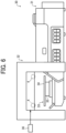
- FIG. 6 is a schematic front view of a fabric image forming system according to a fourth embodiment of the present invention
- FIG. 7 is a schematic side view of the fabric image forming system.
- a fabric image forming system 30 includes an image forming apparatus 31 that forms an image on a fabric, a drying apparatus 32 that performs a drying operation including a fixing operation on the fabric, and a support apparatus 33 that supports the fabric.
- the inkjet image forming apparatus 31 has a known configuration similar to the image forming unit 25 described above, including recording heads that discharge ink, a carriage that holds the recording heads, a carriage guide member that movably guides the carriage, and a carriage moving mechanism that moves the carriage.
- the drying apparatus 32 includes the heating roller 4 described above, a frame similar to the frame 5, a power supply unit similar to the power supply unit 6, and a moving unit similar to the moving unit 8, and is designed in a manner similar to the heat press device 3.
- the heating roller 4 and the power supply unit reciprocate between the position indicated by a solid line and a dashed line in FIG. 6 and the position indicated by a double-dot-and-dash line by an operation of a drive unit.
- the support apparatus 33 includes a mount 34 on which a fabric is held, and a lifter 35 as an approaching and retracting device that moves the fabric held on the mount 34 close to and away from the drying apparatus 32.
- the support apparatus 33 is guided by a rail member and can be moved by a moving mechanism.
- the support apparatus 33 selectively occupies an image forming position at which the fabric on the mount 34 enters the inside of the image forming apparatus 31 and is subjected to image formation, and a drying position facing the drying apparatus 32 illustrated in FIG. 6 .
- the lifter 35 changes the position of the fabric on the mount 34 between a separated position and a proximity position close to the drying apparatus 32 as illustrated in FIG. 6 .
- the lifter 35 is operated to move the mount 34 to the proximity position while the support apparatus 33 occupies the drying position, the fabric held by the mount 34 is pressed against the heating roller 4 at a predetermined pressure.
- the support apparatus 33 occupies the image forming position while the lifter 35 is in a non-operating state or while the mount 34 occupies the separated position at the height illustrated in FIG. 6
- the fabric on the mount 34 faces the image forming unit of the image forming apparatus 31 so that image formation can be performed.
- the lifter 35 has a known configuration such as a cylinder.
- the operator of the fabric image forming system 30 first operates the operating unit of the fabric image forming system 30 to position the support apparatus 33 at the drying position, so that the fabric on which an image is to be formed is held on the mount 34.
- a pretreatment agent is manually applied onto the fabric.
- the operator operates the lifter 35 to position the mount 34 at the proximity position.
- the heating roller 4 When the mount 34 occupies the proximity position, the heating roller 4 starts generating heat. When the heating roller 4 reaches a predetermined temperature, the moving unit operates, so that the heating roller 4 starts reciprocating between the position indicated by a solid line and the position indicated by a double-dot-and-dash line in FIG. 6 . Thus, a drying operation is started. When the heating roller 4 that is generating heat comes into contact with the fabric, the pretreatment agent contained in the fabric is vaporized to generate vapor, and the generated vapor is ejected to the outside of the frame through each guide groove and each through hole of the frame.
- the lifter 35 When it is determined from the temperature of the fabric, the amount of movement of the heating roller 4, and the like that the drying operation has been completed, the lifter 35 operates to return the mount 34 to the separated position. After that, when an image forming operation is started by the operator, the moving mechanism operates to change the position of the support apparatus 33 from the drying position to the image forming position. In a case where an image forming operation is performed without a pretreatment operation after the fabric is held on the mount 34 at the drying position, the position of the support apparatus 33 is changed from the drying position to the image forming position.
- the carriage moving mechanism After the support apparatus 33 occupies the image forming position, the carriage moving mechanism operates to move the recording heads that are discharging ink onto the fabric on the mount 34, and the image forming operation is performed. After a desired image is formed on the fabric, the operation of the carriage moving mechanism comes to a halt, and the discharge of ink from the recording heads also stops. Thus, the image forming operation is completed.
- the moving mechanism operates to change the position of the support apparatus 33 from the image forming position to the drying position, and the lifter 35 then operates to move the mount 34 to the proximity position.
- the heating roller 4 starts generating heat, and a fixing operation on the fabric by the heating roller 4 is performed in a manner similar to the drying operation.
- the vapor generated from the fabric at the time of the fixing operation is ejected to the outside of the frame through each guide groove and each through hole of the frame.
- the lifter 35 operates to return the mount 34 to the separated position, and thus, the fixing operation is completed.
- the support apparatus 33 is located at the drying position, and the pretreatment agent is manually applied when a pretreatment operation is performed.
- a configuration in which the pretreatment agent is automatically applied to the fabric may be adopted for the image forming apparatus 31, as in the third embodiment.
- a configuration in which a pretreatment liquid is discharged from some of the recording heads in the image forming apparatus 31 may be adopted.
- the pretreatment agent applying operation is performed at the image forming position, and the drying operation is performed at the drying position, like the image forming operation and the fixing operation.
- the fabric image forming system 30 may have a configuration in which the respective heating rollers 4A, 4B, and 4C, the respective power supply units 6, and the respective moving units 8A, 8B, and 8C used in the second embodiment are used instead of the heating roller 4, the power supply unit, and the moving unit.
- effects of the second embodiment which are an effect to simplify the configuration and operation control of each of the moving units 8A, 8B, and 8C and lower the costs, and an effect to make the durations of the fixing step and the drying step shorter than in a case where the respective heating rollers are moved in one direction.
- the fourth embodiment described above concerns a configuration in which the lifter 35 as an approaching and retracting device that moves the fabric held on the mount 34 close to and away from the heating roller 4 is provided in the support apparatus 33.
- the support apparatus 33 includes the approaching and retracting device. Accordingly, the fabric held on the mount 34 can be positioned at an optimum height with respect to the image forming unit and the pretreatment agent applicator provided in the image forming apparatus 31, and the pretreatment agent applying operation and the image forming operation on the fabric can be performed in a preferred manner.
- a modification of the fourth embodiment may be a configuration in which the frame that holds the heating roller 4 is vertically movable with respect to the apparatus main body of the drying apparatus 32, and an approaching and retracting device 36 that moves the heating roller 4 close to and away from the fabric held on the mount 34 is provided on the side of the drying apparatus 32 as illustrated in FIG. 6 .
- the drying apparatus 32 includes the approaching and retracting device 36, the configuration of the support apparatus 33 can be simplified, and the costs can be lowered.
- the fabric 9, which is a T-shirt is used as the fabric serving as a recording medium to which the present invention can be applied.
- the fabric is not necessarily a T-shirt, but may be a fabric processed as a garment such as a sweatshirt, a fabric formed with one piece of cloth such as a handkerchief or a towel, a fabric serving as a part of a product such as a tote bag, or the like.
- a fabric drying apparatus includes: a supporting member to support a fabric; a roller-shaped rotatable heating member to come into contact with the fabric to heat the fabric; a frame that holds the heating member such that the heating member is movable with respect to the fabric; a moving unit to move the heating member to bring the heating member into contact with an entire surface of the fabric; and an approaching and retracting unit that brings the fabric supported by the supporting member and the heating member close to and away from each other.
- the fabric drying apparatus further includes a plurality of heating members including the heating member.
- the plurality of heating members move in the same direction.
- At least one heating member of the plurality of heating members moves in a direction different from a direction in which another heating member of the plurality of heating members moves.
- a fabric image forming apparatus includes: an image forming unit to form an image on a fabric; a drying unit including: a roller-shaped rotatable heating member to come into contact with the fabric to heat the fabric; a frame that holds the heating member such that the heating member is movable with respect to the fabric; and a moving unit to move the heating member to bring the heating member into contact with an entire surface of the fabric; a movable support unit to support the fabric and cause the fabric to face the image forming unit and the drying unit; and an approaching and retracting unit to bring the fabric supported by the support unit, and the image forming unit and the drying unit close to and away from each other.
- the fabric image forming apparatus further includes a plurality of heating members including the heating member.
- the plurality of heating members move in the same direction.
- At least one heating member of the plurality of heating members moves in a direction different from a direction in which another heating member of the plurality of heating members moves.
- a fabric image forming system includes: an image forming apparatus to form an image on a fabric; a drying apparatus including a roller-shaped rotatable heating member to come into contact with the fabric to heat the fabric, a frame that holds the heating member such that the heating member is movable with respect to the fabric and is movable close to and away from the fabric, and a moving unit to move the heating member to bring the heating member into contact with an entire surface of the fabric; a movable support apparatus to support the fabric and cause the fabric to face the image forming apparatus and the drying apparatus; and an approaching and retracting device to bring the fabric supported by the support apparatus, and the drying apparatus close to and away from each other.
- the fabric image forming system according to the ninth aspect further includes a plurality of heating members including the heating member.
- the plurality of heating members move in the same direction.
- At least one heating member of the plurality of heating members move in a direction different from a direction in which another heating member of the plurality of heating members moves.
- the approaching and retracting device moves the fabric supported by the support apparatus close to and away from the drying apparatus.
- the approaching and retracting device moves the drying apparatus close to and away from the fabric supported by the support apparatus.
Landscapes
- Engineering & Computer Science (AREA)
- Textile Engineering (AREA)
- Treatment Of Fiber Materials (AREA)
- Ink Jet (AREA)
Abstract
Description
- Embodiments of the present invention relate to a fabric drying apparatus, a fabric image forming apparatus, and a fabric image forming system.
- There has been a known fabric drying apparatus that performs fixing and drying easily and in a short time while releasing vapor generated from a fabric at the time of image fixing in an image forming apparatus for fabrics or at the time of drying of the pretreatment agent applied to a fabric before an image forming process.
- An inkjet image forming apparatus for fabrics applies heat and pressure to a fabric having an image formed thereon, to fix the ink to the fabric. However, a general fabric drying apparatus uses a flat heater as its heat source, and therefore, any gap is not formed between the ink applied to the fabric and the heater at the time of fixing.
- In the above configuration, there are no gaps, and there is no place to escape for the vapor generated due to the heated ink. As a result, the heat from the heater is hardly transmitted to the ink due to the accumulated vapor, which hinders the fixing. Therefore, there is the need to make the fixing time longer, which is a disadvantage.
- Further, when not only the ink but also the pretreatment agent applied to the fabric is dried before the ink to increase image quality and robustness, vapor is generated by the heating as in the case with the ink. Therefore, there is no place for the vapor to escape when the heater is brought into contact and is dried, and it is necessary to make the drying time longer. However, unlike the ink, the pretreatment agent has a disadvantage in that, when the pretreatment agent is heated for a long time, the components of the pretreatment agent are precipitated to whiten the fabric.
- To eliminate the above disadvantages, a method of applying heat from a fabric drying apparatus to a fabric in a non-contact manner is used as an ink fixing method and a method for drying a pretreatment agent. In this case, however, the resin component in the ink is not sufficiently heated, which leads to a disadvantage that is poor robustness or a longer fixing time for sufficiently heating the resin component.
- A method of manually repeating opening and closing of a fabric drying apparatus to release vapor may be used as another method. However, an operator who operates the fabric drying apparatus at the time of fixing or drying the pretreatment agent becomes necessary, and therefore, it is difficult to increase efficiency, which is another disadvantage. A fabric drying apparatus that automatically repeats opening and closing is also known, but has a disadvantage in that the costs are too high.
- To eliminate the above disadvantages, there is a technique suggested for lowering the possibility that the vapor to be generated by heating the moisture contained in a treatment agent will wet a fabric or a heat press machine when heat treatment is performed on a fabric having the treatment agent applied thereto (see
Japanese Patent No. 6620665 -
Japanese Patent No. 6620665 - By this technique, the possibility that the storage target will leak from the storage portion in the second direction is lowered. Accordingly, the storage target is less likely to come into contact with the fabric and the heat press machine, and the possibility that the fabric and the heat press machine will get wet can be lowered.
- A technique for preventing an increase in device size and increasing workability at the time of transferring an image onto a fabric is disclosed as another technique (see
Japanese Patent No. 6794798 -
Japanese Patent No. 6794798 - By this technique, workability at the time of transferring an image onto a fabric is increased.
- A technique for providing a fabric heating device that can be made smaller in size and be operated more easily, and further, is safe and secure is disclosed as yet another technique (see
Japanese Patent No. 6238033 -
Japanese Patent No. 6238033 - By this technique, it is possible to obtain a fabric heating device that can achieve safety, is very easy to handle, is simple, can shorten the working time, and can also achieve miniaturization.
- A technique for providing an iron that can very easily dry and process an object having a curved plane is disclosed as still another technique (see
Japanese Unexamined Utility Model Application Publication No. 59-98898 -
Japanese Unexamined Utility Model Application Publication No. 59-98898 - By this technique, the rotary iron has chemical resistance and non-adhesiveness. Thus, the rotary iron can be used for drying a coated surface and drying a solvent-mixed substance, and can also be easily applied to an object having a curved surface as the surface to be dried. Furthermore, it is very easy to manufacture such a rotary iron.
- By the technique disclosed in
Japanese Patent No. 6620665 - Further, in a case where the object on which an image is to be formed characteristically hardly allows vapor to escape (such as a thick fabric, a finely woven fabric that hardly passes vapor, or a fabric that has no gaps such as glass fiber, instead of cloth or paper having gaps therein), vapor cannot pass through the inside of the object on which an image is to be formed. As a result, the vapor fails to move into the grooves and cannot be collected, which is a disadvantage. This disadvantage cannot be eliminated by the other techniques disclosed in
Japanese Patent No. 6794798 Japanese Patent No. 6238033 Japanese Unexamined Utility Model Application Publication No. 59-98898 - An object of the present invention is to eliminate the above disadvantages, and provide a fabric drying apparatus that can prevent any image formation target and an image forming apparatus from becoming wet due to vapor during drying or fixing, and shorten the heating time to efficiently and inexpensively carry out a reliable pretreatment step and a reliable fixing step.
- According to an aspect of the present disclosure, a fabric drying apparatus includes a supporting member, . a roller-shaped rotatable heating member, a frame, and a moving unit. The supporting member supports a fabric. The heating member comes into contact with the fabric to heat the fabric. The frame holds the heating member such that the heating member is movable with respect to the fabric. The moving unit moves the heating member to bring the heating member into contact with the fabric.
- According to another aspect of the present disclosure, a fabric image forming apparatus includes an image forming unit, a drying unit, a movable support unit, and an approaching and retracting unit. The image forming unit forms an image on a fabric. The drying unit includes a roller-shaped rotatable heating member, a frame, and a moving unit. The roller-shaped rotatable heating member comes into contact with the fabric to heat the fabric. The frame holds the heating member such that the heating member is movable with respect to the fabric. The moving unit moves the heating member to bring the heating member into contact with the fabric. The movable support unit supports the fabric and causes the fabric to face the image forming unit and the drying unit. The approaching and retracting unit brings the fabric supported by the support unit, and the image forming unit and the drying unit close to and away from each other.
- According to still another aspect of the present disclosure, a fabric image forming system includes an image forming apparatus, a drying apparatus, a movable support apparatus, and an approaching and retracting device. The image forming apparatus forms an image on a fabric. The drying apparatus includes a roller-shaped rotatable heating member, a frame, and a moving unit. The roller-shaped rotatable heating member comes into contact with the fabric to heat the fabric. The frame holds the heating member such that the heating member is movable with respect to the fabric and is movable close to and away from the fabric. The moving unit moves the heating member to bring the heating member into contact with the fabric. The movable support apparatus supports the fabric and causes the fabric to face the image forming apparatus and the drying apparatus. The approaching and retracting device brings the fabric supported by the support apparatus and the drying apparatus close to and away from each other.
- According to at least one aspect of the present disclosure, a fabric drying apparatus can be provided that can shorten the heating time to efficiently and inexpensively carry out a pretreatment step and a fixing step.
- A more complete appreciation of embodiments of the present disclosure and many of the attendant advantages and features thereof can be readily obtained and understood from the following detailed description with reference to the accompanying drawings, wherein:
-
FIG. 1 is a schematic view of a fabric drying apparatus according to a first embodiment of the present invention; -
FIG. 2 is a schematic view of a heating roller that is used in the fabric drying apparatus inFIG. 1 ; -
FIG. 3 is a schematic view of a heat press device occupying a closing position in the fabric drying apparatus inFIG. 1 ; -
FIG. 4 is a schematic view of a fabric drying apparatus according to a second embodiment of the present invention; -
FIG. 5 is a schematic view of an image forming apparatus according to a third embodiment of the present invention; -
FIG. 6 is a schematic front view of an image forming system according to a fourth embodiment of the present invention; and -
FIG. 7 is a schematic side view of the image forming system according to the fourth embodiment of the present invention. - The accompanying drawings are intended to depict embodiments of the present disclosure and should not be interpreted to limit the scope thereof. The accompanying drawings are not to be considered as drawn to scale unless explicitly noted. Also, identical or similar reference numerals designate identical or similar components throughout the several views.
- In describing embodiments illustrated in the drawings, specific terminology is employed for the sake of clarity. However, the disclosure of this specification is not intended to be limited to the specific terminology so selected and it is to be understood that each specific element includes all technical equivalents that have a similar function, operate in a similar manner, and achieve a similar result.
- Referring now to the drawings, embodiments of the present disclosure are described below. As used herein, the singular forms "a," "an," and "the" are intended to include the plural forms as well, unless the context clearly indicates otherwise.
-
FIG. 1 illustrates a fabric drying apparatus according to a first embodiment of the present invention. In the drawing, a fabric drying apparatus 1 includes afabric mount 2 as a supporting member, and aheat press device 3 that is openable and closable with respect to thefabric mount 2. Theheat press device 3 includes: aheating roller 4 that is a heating member; aframe 5 that rotatably and movably supports theheating roller 4; apower supply unit 6 that supplies power for heat generation to theheating roller 4; and a movingunit 8 that reciprocates theheating roller 4 and thepower supply unit 6 within a moving range 7 indicated by a double-headed arrow inFIG. 1 . - The
fabric mount 2 has a function of holding afabric 9 such as a T-shirt as a fabric attached to aplacement surface 2a that is the upper surface of thefabric mount 2, and thefabric 9 placed on theplacement surface 2a is held in a stretched state by a member. On thefabric 9, an image is formed in animage formation region 10 indicated by a double-dot-and-dash line in the drawing, by an image forming apparatus such as an inkjet printer. A pretreatment agent may be applied onto theimage formation region 10 prior to image formation. - The
heat press device 3 is openable and closable with respect to thefabric mount 2, the lower end of theframe 5 and the upper end of thefabric mount 2 inFIG. 1 are coupled by a hinge, and theframe 5 is rotatably attached to thefabric mount 2. Theheat press device 3 rotates in aclockwise direction 11a inFIG. 1 to occupy the opening position at which theframe 5 is separated from theplacement surface 2a, and rotates in acounterclockwise direction 11b to occupy the closing position at which theframe 5 is brought in contact with theplacement surface 2a. - The
frame 5 has a shape surrounded in a rectangular shape having aspace 5a formed therein, and aback panel 12 is disposed on a surface facing a surface facing theplacement surface 2a inFIG. 1 . Theback panel 12 is provided to prevent theheating roller 4 from being exposed to the outside, and a material that has a low thermal conductivity such as a heat-resistant resin and hardly transmits the heat from theheating roller 4 to the outside, such as a heat-resistant resin, is used for theback panel 12. Thus, when an operator touches theback panel 12 while theheating roller 4 is generating heat, safety of the operator is ensured. Theback panel 12 has a plurality of throughholes 12a for releasing vapor generated when theheating roller 4 comes into contact with the moisture-containingfabric 9, to the outside through thespace 5a. - The
heating roller 4 is a roller-shaped heating member that is rotatably provided to come into contact with and heat thefabric 9 placed on theplacement surface 2a, and can reciprocate within the moving range 7. Theheating roller 4 is disposed in thespace 5a of theframe 5, and can reciprocate within the moving range 7 as asupport shaft 4a of theheating roller 4 is guided inguide grooves 13 formed in theframe 5. Theheating roller 4 will be described later in greater detail. - The
guide grooves 13 are formed to penetrate both side portions of theframe 5, and has a function of guiding theheating roller 4 in a predetermined direction within the moving range 7. The predetermined direction is a forward direction F of the apparatus, which is the downward direction inFIG. 1 , and a rearward direction R of the apparatus, which is the upward direction inFIG. 1 (these directions will be hereinafter also referred to as the front-rear direction FR), when theheat press device 3 occupies the closing position with respect to thefabric mount 2, and refers to a direction covering at least the entire region of theimage formation region 10 on thefabric 9 held on thefabric mount 2. - Further, when the
heat press device 3 occupies the closing position with respect to thefabric mount 2, theguide grooves 13 also serve as releasing portions that release a gas, such as the vapor (water vapor) generated when theheating roller 4 comes into contact with thefabric 9 and heats thefabric 9, to the outside of thespace 5a. - Referring now to
FIG. 2 , the configuration of a cross-section of theheating roller 4 is now described. The cross-section of theheating roller 4 includes, in order from the inside to the outside, ashaft center portion 14 including thesupport shaft 4a, aheat insulating layer 15, aheating body 16 that uses a nichrome wire or the like as the source of heat, ametal layer 17, a heat-resistant rubber layer 18, and asurface coating layer 19. A silicone-based rubber or the like is used as the heat-resistant rubber layer 18, and a fluorine-based heat-shrinkable resin or the like that excels in heat resistance, chemical resistance, and adhesiveness is used thesurface coating layer 19. As illustrated inFIG. 1 , both end portions of theheating roller 4 are coated with acoating roll material 20 having electrical insulation properties. - The
heating roller 4 has thesupport shaft 4a so protruding from theshaft center portion 14 to the outside of thecoating roll material 20, and a bearing that rotatably supports thecoating roll material 20 is provided between thecoating roll material 20 and theshaft center portion 14. Theheating roller 4 is disposed at a position where theheating roller 4 is pressed against thefabric 9 on theplacement surface 2a with a predetermined pressing force when theheat press device 3 occupies the closing position. With this arrangement, thecoating roll material 20 is rotated by the friction due to the contact with thefabric 9, and thesupport shaft 4a rolls along theguide grooves 13, so that theheating roller 4 can move in the predetermined direction. - The supporting structure for the
heating roller 4 is not limited to this, and may have any configuration with which theheating roller 4 is rotated by the friction caused by contact between theheating roller 4 and thefabric 9, and thesupport shaft 4a can roll and move along theguide grooves 13. - The
power supply unit 6 that supplies power to theheating body 16 of theheating roller 4 to generate heat is disposed near one end ofsupport shaft 4a. A power cord coupled to an external power supply is coupled to thepower supply unit 6, and thepower supply unit 6 and theheating body 16 are coupled to each other by a known method, such as a method of attaching a rotation ring to theheating body 16 using an end of a power cord as a brush, for example. Thepower supply unit 6 is coupled to thesupport shaft 4a, and can move in the predetermined direction integrally with theheating roller 4. - The moving
unit 8 that moves theheating roller 4 and thepower supply unit 6 is disposed near theheating roller 4 and thepower supply unit 6 designed to be movable integrally with theheating roller 4. A general moving unit is adopted as the movingunit 8, and may be a rack and pinion mechanism in which a pinion is provided coaxially with thesupport shaft 4a, a rack meshing with the pinion is disposed along theguide grooves 13, and the pinion is rotated by a motor. In this configuration, when the motor rotates forward and backward, theheating roller 4 and thepower supply unit 6 reciprocate between the position indicated by a solid line and the position indicated by a double-dot-and-dash line inFIG. 1 , or within the moving range 7. The movingunit 8 is not necessarily a rack and pinion mechanism, and some other configuration, such as a known configuration using a motor, a timing pulley, and a timing belt, for example, may be adopted. - Next, operations of the fabric drying apparatus 1 are described.
- First, as illustrated in
FIG. 1 , the operator places theheat press device 3 in the opening position, and causes thefabric mount 2 to hold thefabric 9. Here, thefabric 9 held on thefabric mount 2 is in a state in which a pretreatment agent has been applied at least to theimage formation region 10 or in a state in which image formation with ink has been performed, and is in a wet state in which drying or fixing is to be performed. The operator then rotates theheat press device 3 in thecounterclockwise direction 11b, to position theheat press device 3 at the closing position illustrated inFIG. 3 . After theheat press device 3 occupies the closing position, a start switch provided in the fabric drying apparatus 1 is turned on, to start an operation of the fabric drying apparatus 1. - When the start switch is turned on, power supply from the
power supply unit 6 to theheating body 16 is started, and theheating roller 4 starts heat generation. When a temperature detecting unit detects that the temperature of theheating roller 4 has reached a predetermined temperature, the movingunit 8 starts operating, and theheating roller 4 in contact with thefabric 9, and thepower supply unit 6 start reciprocating within the moving range 7. As theheating roller 4 that is generating heat as above comes into direct contact with thefabric 9, and rolls, theimage formation region 10 is efficiently heated, and drying or fixing is performed. - When the
heating roller 4 that is generating heat comes into contact with thefabric 9 in the wet state described above, moisture such as ink and the pretreatment agent contained in thefabric 9 is vaporized by heat, to generate vapor (water vapor) 21. The generatedvapor 21 is ejected from theguide grooves 13 and the throughholes 12a to the outside of thespace 5a, as indicated by arrow inFIG. 3 . As described above, theheating roller 4 that is generating heat rolls on thefabric 9 while being in direct contact with thefabric 9, so that the drying or fixing operation on thefabric 9 is completed. When it is determined from the temperature of thefabric 9, the amount of movement of theheating roller 4, and the like that the drying or fixing operation has been completed, theheating roller 4 is manually or automatically returned to the initial position indicated by the solid line inFIG. 1 . - After that, the
heat press device 3 is manually or automatically positioned at the opening position, thefabric 9 on which the drying or fixing operation has been completed is removed from thefabric mount 2, and thus, a series of operations by the fabric drying apparatus 1 is completed. - In a case where an opening/closing operation on the
heat press device 3, which is an operation of selectively positioning theheat press device 3 at the opening position or the closing position, is manually performed, there is a need for a mechanism that temporarily holds theheat press device 3 at the opening position, a mechanism that cancels the holding, and the like. This is because theheat press device 3 needs to occupy the opening position when thefabric 9 is attached to or detached from thefabric mount 2, and is to increase safety during the handling of thefabric 9. In a case where an opening/closing operation on theheat press device 3 is automatically performed, it is possible to adopt a configuration in which a rotating shaft that is rotatably supported by thefabric mount 2 and has theheat press device 3 attached thereto is provided in place of a hinge, and a servo motor or a stepping motor that rotationally drives the rotating shaft at a predetermined angle is used. - The
heating roller 4 may be manually moved without the use of the movingunit 8. As an example of this case, there is a configuration in which both end portions of thesupport shaft 4a are projected from therespective guide grooves 13, the projected both end portions are integrated at the upper portion of theback panel 12 to form a grip portion, and the thus formed grip portion is gripped to reciprocate theheating roller 4 within the moving range 7. In this case, the grip portion functions as the moving unit. - In the conventional technique mentioned above, the fabric and the heating member are in contact with each other at the time of a drying or fixing operation. Therefore, there is no place for vapor to escape, and the fabric and the inside of the apparatus become wet due to the generated vapor, which causes various disadvantages. In the configuration according to the present embodiment, however, the position of the
heating roller 4 in contact with thefabric 9 moves and changes its position, and there is constantly a non-contact portion of thefabric 9 with theheating roller 4, so that a place forvapor 21 to escape can be kept without fail. With this configuration, it is possible to achieve effects similar to the effects of a configuration in which theheat press device 3 is detached from thefabric mount 2 to release thevapor 21, and achieve various effects such as shortening of the drying or fixing time, prevention of whitening of thefabric 9 due to the pretreatment agent, an increase in work efficiency, and a cost reduction. - Further, as the
heating roller 4 comes into direct contact with thefabric 9, a fabric having image formation performed thereon with excellent robustness can be obtained in a short time. Furthermore, as theheating roller 4 moves over the entire moving range 7, at least the entireimage formation region 10 of thefabric 9 can be heated. Thus, the fixing step or the drying step for thefabric 9 can be carried out without fail. - In view of the above, according to the present embodiment, it is possible to provide a fabric drying apparatus that can shorten the heating time, and efficiently and inexpensively carry out a reliable pretreatment step and a reliable fixing step.
-
FIG. 4 illustrates a fabric drying apparatus according to a second embodiment of the present invention. Afabric drying apparatus 1A differs from the fabric drying apparatus 1 illustrated inFIG. 1 in that threeheating rollers heating roller 4, threepower supply units 6 corresponding to therespective heating rollers units unit 8. The other components are the same as the corresponding components illustrated inFIG. 1 . - Each of the
heating rollers heating roller 4, and each correspondingpower supply unit 6 is integrally coupled to each support shaft. Theheating rollers ranges - The moving
unit 8A similar to the movingunit 8 is disposed near theheating roller 4A and thepower supply unit 6 that can move integrally with theheating roller 4A. Likewise, the movingunit 8B is disposed near theheating roller 4B and thepower supply unit 6 that can move integrally with theheating roller 4B, and the movingunit 8C is disposed near theheating roller 4C and thepower supply unit 6 that can move integrally with theheating roller 4C. - The moving
unit 8A can reciprocate theheating roller 4A and thepower supply unit 6, the movingunit 8B can reciprocate theheating roller 4B and thepower supply unit 6, and the movingunit 8C can reciprocate theheating roller 4C and thepower supply unit 6. The movingunits corresponding heating rollers power supply units 6 independently of one another, and a control signal for driving is output from acontrol unit 22 to the drive unit of each of the movingunits - Based on the control signal from the
control unit 22, theheating rollers heating rollers heating rollers heating rollers - In the configuration in which all the
heating rollers units - In the configuration in which at least one of the
heating rollers - In the present embodiment, the number of heating rollers is three. However, the number of heating rollers may be any appropriate number, as long as the number of heating rollers is two or greater, and efficient movement in the frame is possible.
-
FIG. 5 illustrates a fabric image forming apparatus according to a third embodiment of the present invention. In the drawing, a fabricimage forming apparatus 23 includes, inside an apparatusmain body 24, animage forming unit 25 that forms an image on a fabric, a dryingunit 26 that performs a drying operation including a fixing operation on the fabric, and asupport unit 27 that supports the fabric. - The inkjet
image forming unit 25 has a known configuration including recording heads that discharges ink, a carriage that holds the recording heads, a carriage guide member that movably guides the carriage, and a carriage moving mechanism that moves the carriage. - The drying
unit 26 includes theheating roller 4 described above, a frame similar to theframe 5, a power supply unit similar to thepower supply unit 6, and a moving unit similar to the movingunit 8, and is designed in a manner similar to theheat press device 3. Theheating roller 4 and the power supply unit reciprocate between the position indicated by a solid line and a dashed line inFIG. 5 and the position indicated by a double-dot-and-dash line by an operation of a drive unit. - The
support unit 27 includes amount 28 on which a fabric is held, and alifter 29 as an approaching and retracting unit that moves the fabric held on themount 28 close to and away from theimage forming unit 25 and the dryingunit 26. Thesupport unit 27 is guided by a rail member and can be moved by a moving mechanism. Thesupport unit 27 selectively occupies an image forming position facing theimage forming unit 25 as indicated by a solid line inFIG. 5 , a drying position facing the dryingunit 26 as indicated by a dot-and-dash line inFIG. 5 , and an exposed position located outside the apparatusmain body 24 as indicated by a double-dot-and-dash line inFIG. 5 . - The
lifter 29 changes the position of the fabric on themount 28 between a separated position illustrated in the drawing and a proximity position close to theimage forming unit 25 and the dryingunit 26. When thelifter 29 is operated to move themount 28 to the proximity position while thesupport unit 27 occupies the drying position, the fabric held by themount 28 is pressed against theheating roller 4 at a predetermined pressure. Thelifter 29 has a known configuration like a cylinder that can vertically move themount 28. - Operations of the fabric
image forming apparatus 23 described above are now described. The operator of the fabricimage forming apparatus 23 first operates the operating unit of the fabricimage forming apparatus 23 to position thesupport unit 27 at the exposed position, so that the fabric on which an image is to be formed is held on themount 28. In a case where pretreatment is to be performed on the fabric at this point of time, a pretreatment agent may be manually applied to the fabric, or a pretreatment liquid may be discharged from some of the recording heads in theimage forming unit 25. In a case where a pretreatment agent is applied, the operator positions thesupport unit 27 at the drying position, and then operates thelifter 29 to position themount 28 at the proximity position. - When the
mount 28 occupies the proximity position, theheating roller 4 starts generating heat. When theheating roller 4 reaches a predetermined temperature, the moving unit operates, so that theheating roller 4 starts reciprocating between the position indicated by a solid line and the position indicated by a double-dot-and-dash line inFIG. 5 . Thus, a drying operation is started. When theheating roller 4 that is generating heat comes into contact with the fabric, the pretreatment agent contained in the fabric is vaporized to generate vapor, and the generated vapor is ejected to the outside of the frame through each guide groove and each through hole of the frame, and is further ejected to the outside of the apparatusmain body 24 via through holes formed in the apparatusmain body 24. - When it is determined from the temperature of the fabric, the amount of movement of the
heating roller 4, and the like that the drying operation has been completed, thelifter 29 operates to return themount 28 to the separated position. After that, when an image forming operation is started by the operator, the moving mechanism operates to change the position of thesupport unit 27 from the drying position to the image forming position. In a case where an image forming operation is performed without a pretreatment operation after the fabric is held on themount 28 at the exposed position, the position of thesupport unit 27 is changed from the exposed position to the image forming position. - After the
support unit 27 occupies the image forming position, thelifter 29 operates to move themount 28 to the proximity position, and the carriage moving mechanism then operates to move the recording heads that are discharging ink onto the fabric on themount 28. Thus, the image forming operation is performed. After a desired image is formed on the fabric, the operation of the carriage moving mechanism is stopped, and the discharge of ink from the recording heads is also stopped. Thelifter 29 then operates to return themount 28 to the separated position. - When the
mount 28 occupies the separated position, the moving mechanism operates to change the position of thesupport unit 27 from the image forming position to the drying position, and thelifter 29 then operates to move themount 28 to the proximity position. When themount 28 occupies the proximity position, theheating roller 4 starts generating heat, so that a fixing operation on the fabric by theheating roller 4 is performed like the drying operation. The vapor generated from the fabric at the time of the fixing operation is ejected to the outside of the frame through each guide groove and each through hole of the frame, and is further ejected to the outside of the apparatusmain body 24 via through holes formed in the apparatusmain body 24. When it is determined from the temperature of the fabric, the amount of movement of theheating roller 4, and the like that the fixing operation has been completed, thelifter 29 operates to return themount 28 to the separated position, and thus, the fixing operation is completed. - By this series of operations, it is possible to achieve the same effect as an effect of the first embodiment, which is the effect to provide a fabric image forming apparatus that can shorten the heating time to efficiently and inexpensively carry out a reliable pretreatment step and a reliable fixing step.
- In the third embodiment, the
support unit 27 is located at the exposed position and the pretreatment agent is manually applied when a pretreatment operation is performed. However, a configuration in which the pretreatment agent is automatically applied to the fabric may be adopted for theimage forming unit 25. In this case, the pretreatment agent applying operation is performed at the image forming position, and the drying operation is performed at the drying position, like the image forming operation and the fixing operation. Accordingly, the pretreatment operation and the drying operation can be automatically performed, the image forming operation and the fixing operation can be further performed subsequent to the drying operation, and the series of steps can be fully automatically carried out to simplify and shorten the process. - The fabric
image forming apparatus 23 may have a configuration in which theheating rollers power supply units 6, and the movingunits heating roller 4, the power supply unit, and the moving unit. - With this configuration, it is possible to achieve the same effects as effects of the second embodiment, which are an effect to simplify the configuration and operation control of each of the moving
units -
FIG. 6 is a schematic front view of a fabric image forming system according to a fourth embodiment of the present invention, andFIG. 7 is a schematic side view of the fabric image forming system. In the drawing, a fabricimage forming system 30 includes animage forming apparatus 31 that forms an image on a fabric, a dryingapparatus 32 that performs a drying operation including a fixing operation on the fabric, and asupport apparatus 33 that supports the fabric. - The inkjet
image forming apparatus 31 has a known configuration similar to theimage forming unit 25 described above, including recording heads that discharge ink, a carriage that holds the recording heads, a carriage guide member that movably guides the carriage, and a carriage moving mechanism that moves the carriage. - The drying
apparatus 32 includes theheating roller 4 described above, a frame similar to theframe 5, a power supply unit similar to thepower supply unit 6, and a moving unit similar to the movingunit 8, and is designed in a manner similar to theheat press device 3. Theheating roller 4 and the power supply unit reciprocate between the position indicated by a solid line and a dashed line inFIG. 6 and the position indicated by a double-dot-and-dash line by an operation of a drive unit. - The
support apparatus 33 includes amount 34 on which a fabric is held, and alifter 35 as an approaching and retracting device that moves the fabric held on themount 34 close to and away from the dryingapparatus 32. Thesupport apparatus 33 is guided by a rail member and can be moved by a moving mechanism. Thesupport apparatus 33 selectively occupies an image forming position at which the fabric on themount 34 enters the inside of theimage forming apparatus 31 and is subjected to image formation, and a drying position facing the dryingapparatus 32 illustrated inFIG. 6 . - The
lifter 35 changes the position of the fabric on themount 34 between a separated position and a proximity position close to the dryingapparatus 32 as illustrated inFIG. 6 . When thelifter 35 is operated to move themount 34 to the proximity position while thesupport apparatus 33 occupies the drying position, the fabric held by themount 34 is pressed against theheating roller 4 at a predetermined pressure. When thesupport apparatus 33 occupies the image forming position while thelifter 35 is in a non-operating state or while themount 34 occupies the separated position at the height illustrated inFIG. 6 , the fabric on themount 34 faces the image forming unit of theimage forming apparatus 31 so that image formation can be performed. Like thelifter 29, thelifter 35 has a known configuration such as a cylinder. - Operations of the fabric
image forming system 30 described above are now described. The operator of the fabricimage forming system 30 first operates the operating unit of the fabricimage forming system 30 to position thesupport apparatus 33 at the drying position, so that the fabric on which an image is to be formed is held on themount 34. In a case where pretreatment is to be performed on the fabric at this point of time, a pretreatment agent is manually applied onto the fabric. After the pretreatment agent is applied, the operator operates thelifter 35 to position themount 34 at the proximity position. - When the
mount 34 occupies the proximity position, theheating roller 4 starts generating heat. When theheating roller 4 reaches a predetermined temperature, the moving unit operates, so that theheating roller 4 starts reciprocating between the position indicated by a solid line and the position indicated by a double-dot-and-dash line inFIG. 6 . Thus, a drying operation is started. When theheating roller 4 that is generating heat comes into contact with the fabric, the pretreatment agent contained in the fabric is vaporized to generate vapor, and the generated vapor is ejected to the outside of the frame through each guide groove and each through hole of the frame. - When it is determined from the temperature of the fabric, the amount of movement of the
heating roller 4, and the like that the drying operation has been completed, thelifter 35 operates to return themount 34 to the separated position. After that, when an image forming operation is started by the operator, the moving mechanism operates to change the position of thesupport apparatus 33 from the drying position to the image forming position. In a case where an image forming operation is performed without a pretreatment operation after the fabric is held on themount 34 at the drying position, the position of thesupport apparatus 33 is changed from the drying position to the image forming position. - After the
support apparatus 33 occupies the image forming position, the carriage moving mechanism operates to move the recording heads that are discharging ink onto the fabric on themount 34, and the image forming operation is performed. After a desired image is formed on the fabric, the operation of the carriage moving mechanism comes to a halt, and the discharge of ink from the recording heads also stops. Thus, the image forming operation is completed. - After the image forming operation is completed, the moving mechanism operates to change the position of the
support apparatus 33 from the image forming position to the drying position, and thelifter 35 then operates to move themount 34 to the proximity position. As themount 34 occupies the proximity position, theheating roller 4 starts generating heat, and a fixing operation on the fabric by theheating roller 4 is performed in a manner similar to the drying operation. The vapor generated from the fabric at the time of the fixing operation is ejected to the outside of the frame through each guide groove and each through hole of the frame. When it is determined from the temperature of the fabric, the amount of movement of theheating roller 4, and the like that the fixing operation has been completed, thelifter 35 operates to return themount 34 to the separated position, and thus, the fixing operation is completed. - By this series of operations, it is possible to achieve the same effect as an effect of the first embodiment, which is the effect to provide a fabric image forming system that can shorten the heating time to efficiently and inexpensively carry out a reliable pretreatment step and a reliable fixing step.
- In the fourth embodiment, the
support apparatus 33 is located at the drying position, and the pretreatment agent is manually applied when a pretreatment operation is performed. However, a configuration in which the pretreatment agent is automatically applied to the fabric may be adopted for theimage forming apparatus 31, as in the third embodiment. As an example, a configuration in which a pretreatment liquid is discharged from some of the recording heads in theimage forming apparatus 31 may be adopted. In this case, the pretreatment agent applying operation is performed at the image forming position, and the drying operation is performed at the drying position, like the image forming operation and the fixing operation. With this arrangement, the series of steps is fully automatically carried out, and thus, the process can be simplified and shortened. - The fabric
image forming system 30 may have a configuration in which therespective heating rollers power supply units 6, and the respective movingunits heating roller 4, the power supply unit, and the moving unit. - With this configuration, it is possible to achieve the same effects as effects of the second embodiment, which are an effect to simplify the configuration and operation control of each of the moving
units - The fourth embodiment described above concerns a configuration in which the
lifter 35 as an approaching and retracting device that moves the fabric held on themount 34 close to and away from theheating roller 4 is provided in thesupport apparatus 33. In this configuration, thesupport apparatus 33 includes the approaching and retracting device. Accordingly, the fabric held on themount 34 can be positioned at an optimum height with respect to the image forming unit and the pretreatment agent applicator provided in theimage forming apparatus 31, and the pretreatment agent applying operation and the image forming operation on the fabric can be performed in a preferred manner. - A modification of the fourth embodiment may be a configuration in which the frame that holds the
heating roller 4 is vertically movable with respect to the apparatus main body of the dryingapparatus 32, and an approaching and retractingdevice 36 that moves theheating roller 4 close to and away from the fabric held on themount 34 is provided on the side of the dryingapparatus 32 as illustrated inFIG. 6 . In this configuration, the dryingapparatus 32 includes the approaching and retractingdevice 36, the configuration of thesupport apparatus 33 can be simplified, and the costs can be lowered. - In each of the above embodiments, the
fabric 9, which is a T-shirt, is used as the fabric serving as a recording medium to which the present invention can be applied. However, the fabric is not necessarily a T-shirt, but may be a fabric processed as a garment such as a sweatshirt, a fabric formed with one piece of cloth such as a handkerchief or a towel, a fabric serving as a part of a product such as a tote bag, or the like. - Aspects of embodiments of the present invention are, for example, as follows.
- A fabric drying apparatus includes: a supporting member to support a fabric; a roller-shaped rotatable heating member to come into contact with the fabric to heat the fabric; a frame that holds the heating member such that the heating member is movable with respect to the fabric; a moving unit to move the heating member to bring the heating member into contact with an entire surface of the fabric; and an approaching and retracting unit that brings the fabric supported by the supporting member and the heating member close to and away from each other.
- The fabric drying apparatus according to the first aspect further includes a plurality of heating members including the heating member.
- In the fabric drying apparatus according to the second aspect, the plurality of heating members move in the same direction.
- In the fabric drying apparatus according to the second aspect, at least one heating member of the plurality of heating members moves in a direction different from a direction in which another heating member of the plurality of heating members moves.
- A fabric image forming apparatus includes: an image forming unit to form an image on a fabric; a drying unit including: a roller-shaped rotatable heating member to come into contact with the fabric to heat the fabric; a frame that holds the heating member such that the heating member is movable with respect to the fabric; and a moving unit to move the heating member to bring the heating member into contact with an entire surface of the fabric; a movable support unit to support the fabric and cause the fabric to face the image forming unit and the drying unit; and an approaching and retracting unit to bring the fabric supported by the support unit, and the image forming unit and the drying unit close to and away from each other.
- The fabric image forming apparatus according to the fifth aspect further includes a plurality of heating members including the heating member.
- In the fabric image forming apparatus according to the sixth aspect, the plurality of heating members move in the same direction.
- In the fabric image forming apparatus according to the sixth aspect, at least one heating member of the plurality of heating members moves in a direction different from a direction in which another heating member of the plurality of heating members moves.
- A fabric image forming system includes: an image forming apparatus to form an image on a fabric; a drying apparatus including a roller-shaped rotatable heating member to come into contact with the fabric to heat the fabric, a frame that holds the heating member such that the heating member is movable with respect to the fabric and is movable close to and away from the fabric, and a moving unit to move the heating member to bring the heating member into contact with an entire surface of the fabric; a movable support apparatus to support the fabric and cause the fabric to face the image forming apparatus and the drying apparatus; and an approaching and retracting device to bring the fabric supported by the support apparatus, and the drying apparatus close to and away from each other.
- The fabric image forming system according to the ninth aspect further includes a plurality of heating members including the heating member.
- In the fabric image forming system according to the tenth aspect, the plurality of heating members move in the same direction.
- In the fabric image forming system according to the tenth aspect, at least one heating member of the plurality of heating members move in a direction different from a direction in which another heating member of the plurality of heating members moves.
- In the fabric image forming system according to any one of the ninth to twelfth aspects, the approaching and retracting device moves the fabric supported by the support apparatus close to and away from the drying apparatus.
- In the fabric image forming system according to any one of the ninth to twelfth aspects, the approaching and retracting device moves the drying apparatus close to and away from the fabric supported by the support apparatus.
- The above-described embodiments are illustrative and do not limit the present disclosure. Thus, numerous additional modifications and variations are possible in light of the above teachings, unless otherwise specified.
- Although most preferable advantages have been described above, advantages of the present disclosure are not limited to the advantages described above.
Claims (14)
- A fabric drying apparatus, comprising:a supporting member (2) to support a fabric;a roller-shaped rotatable heating member (4) to come into contact with the fabric to heat the fabric;a frame (5) that holds the heating member (4) such that the heating member (4) is movable with respect to the fabric; anda moving unit (8) to move the heating member (4) to bring the heating member (4) into contact with the fabric.
- The fabric drying apparatus according to claim 1, further comprising a plurality of heating members (4A, 4B, 4C) including the heating member (4).
- The fabric drying apparatus according to claim 2,
wherein the plurality of heating members (4A, 4B, 4C) move in the same direction. - The fabric drying apparatus according to claim 2,
wherein at least one heating member of the plurality of heating members (4A, 4B, 4C) moves in a direction different from a direction in which another heating member of the plurality of heating members (4A, 4B, 4C) moves. - A fabric image forming apparatus, comprising:an image forming unit (25) to form an image on a fabric;a drying unit (26) including:a roller-shaped rotatable heating member (4) to come into contact with the fabric to heat the fabric;a frame (5) that holds the heating member (4) such that the heating member (4) is movable with respect to the fabric; anda moving unit (8) to move the heating member (4) to bring the heating member (4) into contact with the fabric;a movable support unit (27) to support the fabric and cause the fabric to face the image forming unit (25) and the drying unit (26); andan approaching and retracting unit (29) to bring the fabric supported by the support unit (27), and the image forming unit (25) and the drying unit (26) close to and away from each other.
- The fabric image forming apparatus according to claim 5, further comprising a plurality of heating members (4A, 4B, 4C) including the heating member (4).
- The fabric image forming apparatus according to claim 6,
wherein the plurality of heating members (4A, 4B, 4C) move in the same direction. - The fabric image forming apparatus according to claim 6,
wherein at least one heating member of the plurality of heating members (4A, 4B, 4C) moves in a direction different from a direction in which another heating member of the plurality of heating members (4A, 4B, 4C) moves. - A fabric image forming system, comprising:an image forming apparatus (31) to form an image on a fabric;a drying apparatus (32) including:a roller-shaped rotatable heating member (4) to come into contact with the fabric to heat the fabric;a frame (5) that holds the heating member (4) such that the heating member (4) is movable with respect to the fabric and is movable close to and away from the fabric; anda moving unit (8) to move the heating member (4) to bring the heating member (4) into contact with the fabric;a movable support apparatus (33) to support the fabric and cause the fabric to face the image forming apparatus (31) and the drying apparatus (32); andan approaching and retracting device (35) to bring the fabric supported by the support apparatus (33) and the drying apparatus (32) close to and away from each other.
- The fabric image forming system according to claim 9, further comprising a plurality of heating members (4A, 4B, 4C) including the heating member (4).
- The fabric image forming system according to claim 10,
wherein the plurality of heating members (4A, 4B, 4C) move in the same direction. - The fabric image forming system according to claim 10,
wherein at least one heating member of the plurality of heating members (4A, 4B, 4C) moves in a direction different from a direction in which another heating member of the plurality of heating members (4A, 4B, 4C) moves. - The fabric image forming system according to any one of claims 9 to 12, wherein the approaching and retracting device (35) moves the fabric supported by the support apparatus (33) close to and away from the drying apparatus (32).
- The fabric image forming system according to any one of claims 9 to 12, wherein the approaching and retracting device moves the drying apparatus (32) close to and away from the fabric supported by the support apparatus (33).
Applications Claiming Priority (1)
| Application Number | Priority Date | Filing Date | Title |
|---|---|---|---|
| JP2022205536A JP2024089961A (en) | 2022-12-22 | 2022-12-22 | Fabric drying device, fabric image forming device, and fabric image forming system |
Publications (2)
| Publication Number | Publication Date |
|---|---|
| EP4407085A1 true EP4407085A1 (en) | 2024-07-31 |
| EP4407085B1 EP4407085B1 (en) | 2026-02-25 |
Family
ID=89224574
Family Applications (1)
| Application Number | Title | Priority Date | Filing Date |
|---|---|---|---|
| EP23218062.0A Active EP4407085B1 (en) | 2022-12-22 | 2023-12-19 | Fabric image forming apparatus |
Country Status (3)
| Country | Link |
|---|---|
| EP (1) | EP4407085B1 (en) |
| JP (1) | JP2024089961A (en) |
| CN (1) | CN118238531A (en) |
Citations (8)
| Publication number | Priority date | Publication date | Assignee | Title |
|---|---|---|---|---|
| JPS5998898U (en) | 1982-12-24 | 1984-07-04 | グンゼ株式会社 | rotary iron |
| JP6238033B1 (en) | 2016-10-21 | 2017-11-29 | 齋藤 敬 | Textile heating device, textile printing method and textile printing device |
| CN108951056A (en) * | 2018-07-29 | 2018-12-07 | 张祖红 | A kind of efficient ironing machine of multi roll |
| CN209307714U (en) * | 2019-01-02 | 2019-08-27 | 佛山市顺德区威斯嘉服装有限公司 | Ironing apparatus is used in a kind of processing of garment production |
| CN209481978U (en) * | 2018-10-30 | 2019-10-11 | 界首市波菲特服饰有限公司 | The closed dyeing and printing device of environmental garment fabric |
| JP6620665B2 (en) | 2016-04-28 | 2019-12-18 | ブラザー工業株式会社 | Cloth support base |
| JP6794798B2 (en) | 2016-11-25 | 2020-12-02 | 株式会社リコー | A device that heats the fabric, a tray that holds the fabric, and how to add an image to the fabric |
| CN213681341U (en) * | 2020-11-19 | 2021-07-13 | 重庆红果服饰有限公司 | Ironing device for sweater fabric processing |
-
2022
- 2022-12-22 JP JP2022205536A patent/JP2024089961A/en active Pending
-
2023
- 2023-11-29 CN CN202311620034.6A patent/CN118238531A/en active Pending
- 2023-12-19 EP EP23218062.0A patent/EP4407085B1/en active Active
Patent Citations (8)
| Publication number | Priority date | Publication date | Assignee | Title |
|---|---|---|---|---|
| JPS5998898U (en) | 1982-12-24 | 1984-07-04 | グンゼ株式会社 | rotary iron |
| JP6620665B2 (en) | 2016-04-28 | 2019-12-18 | ブラザー工業株式会社 | Cloth support base |
| JP6238033B1 (en) | 2016-10-21 | 2017-11-29 | 齋藤 敬 | Textile heating device, textile printing method and textile printing device |
| JP6794798B2 (en) | 2016-11-25 | 2020-12-02 | 株式会社リコー | A device that heats the fabric, a tray that holds the fabric, and how to add an image to the fabric |
| CN108951056A (en) * | 2018-07-29 | 2018-12-07 | 张祖红 | A kind of efficient ironing machine of multi roll |
| CN209481978U (en) * | 2018-10-30 | 2019-10-11 | 界首市波菲特服饰有限公司 | The closed dyeing and printing device of environmental garment fabric |
| CN209307714U (en) * | 2019-01-02 | 2019-08-27 | 佛山市顺德区威斯嘉服装有限公司 | Ironing apparatus is used in a kind of processing of garment production |
| CN213681341U (en) * | 2020-11-19 | 2021-07-13 | 重庆红果服饰有限公司 | Ironing device for sweater fabric processing |
Also Published As
| Publication number | Publication date |
|---|---|
| JP2024089961A (en) | 2024-07-04 |
| EP4407085B1 (en) | 2026-02-25 |
| CN118238531A (en) | 2024-06-25 |
Similar Documents
| Publication | Publication Date | Title |
|---|---|---|
| US10550514B2 (en) | Cloth heating apparatus, cloth heating method, method of applying image to cloth, medium heating apparatus | |
| US10625522B2 (en) | Image adding system, printer, cloth holder, and holder with cloth | |
| EP3399837B1 (en) | Liquid discharge apparatus | |
| JP6859876B2 (en) | A device that heats the fabric, a method that heats the fabric, a method that gives an image to the fabric, a device that heats the medium. | |
| US11059303B2 (en) | Recording medium holder and image forming system | |
| EP4407085B1 (en) | Fabric image forming apparatus | |
| JP2018084013A (en) | Apparatus for heating fabric, tray for holding fabric, and method for applying image to fabric | |
| JP2004122067A (en) | Nozzle cleaning device and substrate processing apparatus provided with this nozzle cleaning device | |
| JP7172252B2 (en) | heating device | |
| CN104943367A (en) | Printing apparatus and cockle removing method | |
| US10782068B2 (en) | Apparatus and method for treating fabric | |
| US11173727B2 (en) | Printing apparatus and printing method | |
| JP7130941B2 (en) | Heating device, image application device, image application method | |
| JP2011208306A (en) | Print processing apparatus | |
| JP2011208287A (en) | Textile-printing treatment apparatus | |
| JP2011162917A (en) | Printing treatment apparatus | |
| TWI898420B (en) | Gravure transfer printing machine | |
| JP2011058130A (en) | Color developing machine of direct print using sublimation dye ink | |
| CN221235750U (en) | Intelligent textile printing and dyeing equipment | |
| US6719465B2 (en) | Rotating processor | |
| JP2011195986A (en) | Textile printing treatment apparatus | |
| RU2569601C1 (en) | Method of fixing bilateral colourful image reproduced on paper tape using jet modules, and device for its implementation | |
| CN119663585A (en) | Polishing machine for velvet fabric | |
| JP2025079573A (en) | dryer | |
| CN117127344A (en) | Ironing equipment |
Legal Events
| Date | Code | Title | Description |
|---|---|---|---|
| PUAI | Public reference made under article 153(3) epc to a published international application that has entered the european phase |
Free format text: ORIGINAL CODE: 0009012 |
|
| STAA | Information on the status of an ep patent application or granted ep patent |
Free format text: STATUS: REQUEST FOR EXAMINATION WAS MADE |
|
| 17P | Request for examination filed |
Effective date: 20231219 |
|
| AK | Designated contracting states |
Kind code of ref document: A1 Designated state(s): AL AT BE BG CH CY CZ DE DK EE ES FI FR GB GR HR HU IE IS IT LI LT LU LV MC ME MK MT NL NO PL PT RO RS SE SI SK SM TR |
|
| RIC1 | Information provided on ipc code assigned before grant |
Ipc: D06C 15/00 20060101AFI20250812BHEP |
|
| GRAP | Despatch of communication of intention to grant a patent |
Free format text: ORIGINAL CODE: EPIDOSNIGR1 |
|
| STAA | Information on the status of an ep patent application or granted ep patent |
Free format text: STATUS: GRANT OF PATENT IS INTENDED |
|
| INTG | Intention to grant announced |
Effective date: 20251001 |
|
| RIN1 | Information on inventor provided before grant (corrected) |
Inventor name: HOSAKA, SHIGETOSHI |
|
| GRAS | Grant fee paid |
Free format text: ORIGINAL CODE: EPIDOSNIGR3 |
|
| GRAA | (expected) grant |
Free format text: ORIGINAL CODE: 0009210 |
|
| STAA | Information on the status of an ep patent application or granted ep patent |
Free format text: STATUS: THE PATENT HAS BEEN GRANTED |
|
| AK | Designated contracting states |
Kind code of ref document: B1 Designated state(s): AL AT BE BG CH CY CZ DE DK EE ES FI FR GB GR HR HU IE IS IT LI LT LU LV MC ME MK MT NL NO PL PT RO RS SE SI SK SM TR |
|
| P01 | Opt-out of the competence of the unified patent court (upc) registered |
Free format text: CASE NUMBER: UPC_APP_0001502_4407085/2026 Effective date: 20260116 |
|
| REG | Reference to a national code |
Ref country code: CH Ref legal event code: F10 Free format text: ST27 STATUS EVENT CODE: U-0-0-F10-F00 (AS PROVIDED BY THE NATIONAL OFFICE) Effective date: 20260225 Ref country code: GB Ref legal event code: FG4D |
|
| REG | Reference to a national code |
Ref country code: DE Ref legal event code: R096 Ref document number: 602023012582 Country of ref document: DE |
|
| REG | Reference to a national code |
Ref country code: IE Ref legal event code: FG4D |