EP4407064A1 - Gas wiping nozzle and method for manufacturing hot dip metal-plated steel strip and gas wiping nozzle - Google Patents
Gas wiping nozzle and method for manufacturing hot dip metal-plated steel strip and gas wiping nozzle Download PDFInfo
- Publication number
- EP4407064A1 EP4407064A1 EP22903844.3A EP22903844A EP4407064A1 EP 4407064 A1 EP4407064 A1 EP 4407064A1 EP 22903844 A EP22903844 A EP 22903844A EP 4407064 A1 EP4407064 A1 EP 4407064A1
- Authority
- EP
- European Patent Office
- Prior art keywords
- gas wiping
- wiping nozzle
- steel strip
- ppi
- nozzle
- Prior art date
- Legal status (The legal status is an assumption and is not a legal conclusion. Google has not performed a legal analysis and makes no representation as to the accuracy of the status listed.)
- Pending
Links
Images

Classifications
-
- C—CHEMISTRY; METALLURGY
- C23—COATING METALLIC MATERIAL; COATING MATERIAL WITH METALLIC MATERIAL; CHEMICAL SURFACE TREATMENT; DIFFUSION TREATMENT OF METALLIC MATERIAL; COATING BY VACUUM EVAPORATION, BY SPUTTERING, BY ION IMPLANTATION OR BY CHEMICAL VAPOUR DEPOSITION, IN GENERAL; INHIBITING CORROSION OF METALLIC MATERIAL OR INCRUSTATION IN GENERAL
- C23C—COATING METALLIC MATERIAL; COATING MATERIAL WITH METALLIC MATERIAL; SURFACE TREATMENT OF METALLIC MATERIAL BY DIFFUSION INTO THE SURFACE, BY CHEMICAL CONVERSION OR SUBSTITUTION; COATING BY VACUUM EVAPORATION, BY SPUTTERING, BY ION IMPLANTATION OR BY CHEMICAL VAPOUR DEPOSITION, IN GENERAL
- C23C2/00—Hot-dipping or immersion processes for applying the coating material in the molten state without affecting the shape; Apparatus therefor
- C23C2/14—Removing excess of molten coatings; Controlling or regulating the coating thickness
- C23C2/16—Removing excess of molten coatings; Controlling or regulating the coating thickness using fluids under pressure, e.g. air knives
- C23C2/18—Removing excess of molten coatings from elongated material
- C23C2/20—Strips; Plates
-
- B—PERFORMING OPERATIONS; TRANSPORTING
- B05—SPRAYING OR ATOMISING IN GENERAL; APPLYING FLUENT MATERIALS TO SURFACES, IN GENERAL
- B05B—SPRAYING APPARATUS; ATOMISING APPARATUS; NOZZLES
- B05B1/00—Nozzles, spray heads or other outlets, with or without auxiliary devices such as valves, heating means
- B05B1/005—Nozzles or other outlets specially adapted for discharging one or more gases
-
- B—PERFORMING OPERATIONS; TRANSPORTING
- B05—SPRAYING OR ATOMISING IN GENERAL; APPLYING FLUENT MATERIALS TO SURFACES, IN GENERAL
- B05B—SPRAYING APPARATUS; ATOMISING APPARATUS; NOZZLES
- B05B1/00—Nozzles, spray heads or other outlets, with or without auxiliary devices such as valves, heating means
- B05B1/02—Nozzles, spray heads or other outlets, with or without auxiliary devices such as valves, heating means designed to produce a jet, spray, or other discharge of particular shape or nature, e.g. in single drops, or having an outlet of particular shape
- B05B1/04—Nozzles, spray heads or other outlets, with or without auxiliary devices such as valves, heating means designed to produce a jet, spray, or other discharge of particular shape or nature, e.g. in single drops, or having an outlet of particular shape in flat form, e.g. fan-like, sheet-like
-
- B—PERFORMING OPERATIONS; TRANSPORTING
- B05—SPRAYING OR ATOMISING IN GENERAL; APPLYING FLUENT MATERIALS TO SURFACES, IN GENERAL
- B05B—SPRAYING APPARATUS; ATOMISING APPARATUS; NOZZLES
- B05B1/00—Nozzles, spray heads or other outlets, with or without auxiliary devices such as valves, heating means
- B05B1/02—Nozzles, spray heads or other outlets, with or without auxiliary devices such as valves, heating means designed to produce a jet, spray, or other discharge of particular shape or nature, e.g. in single drops, or having an outlet of particular shape
- B05B1/04—Nozzles, spray heads or other outlets, with or without auxiliary devices such as valves, heating means designed to produce a jet, spray, or other discharge of particular shape or nature, e.g. in single drops, or having an outlet of particular shape in flat form, e.g. fan-like, sheet-like
- B05B1/044—Slits, e.g. narrow openings defined by two straight and parallel lips; Elongated outlets for producing very wide discharges, e.g. fluid curtains
-
- B—PERFORMING OPERATIONS; TRANSPORTING
- B05—SPRAYING OR ATOMISING IN GENERAL; APPLYING FLUENT MATERIALS TO SURFACES, IN GENERAL
- B05B—SPRAYING APPARATUS; ATOMISING APPARATUS; NOZZLES
- B05B15/00—Details of spraying plant or spraying apparatus not otherwise provided for; Accessories
- B05B15/50—Arrangements for cleaning; Arrangements for preventing deposits, drying-out or blockage; Arrangements for detecting improper discharge caused by the presence of foreign matter
-
- B—PERFORMING OPERATIONS; TRANSPORTING
- B05—SPRAYING OR ATOMISING IN GENERAL; APPLYING FLUENT MATERIALS TO SURFACES, IN GENERAL
- B05C—APPARATUS FOR APPLYING FLUENT MATERIALS TO SURFACES, IN GENERAL
- B05C11/00—Component parts, details or accessories not specifically provided for in groups B05C1/00 - B05C9/00
- B05C11/02—Apparatus for spreading or distributing liquids or other fluent materials already applied to a surface ; Controlling means therefor; Control of the thickness of a coating by spreading or distributing liquids or other fluent materials already applied to the coated surface
- B05C11/06—Apparatus for spreading or distributing liquids or other fluent materials already applied to a surface ; Controlling means therefor; Control of the thickness of a coating by spreading or distributing liquids or other fluent materials already applied to the coated surface with a blast of gas or vapour
-
- C—CHEMISTRY; METALLURGY
- C23—COATING METALLIC MATERIAL; COATING MATERIAL WITH METALLIC MATERIAL; CHEMICAL SURFACE TREATMENT; DIFFUSION TREATMENT OF METALLIC MATERIAL; COATING BY VACUUM EVAPORATION, BY SPUTTERING, BY ION IMPLANTATION OR BY CHEMICAL VAPOUR DEPOSITION, IN GENERAL; INHIBITING CORROSION OF METALLIC MATERIAL OR INCRUSTATION IN GENERAL
- C23C—COATING METALLIC MATERIAL; COATING MATERIAL WITH METALLIC MATERIAL; SURFACE TREATMENT OF METALLIC MATERIAL BY DIFFUSION INTO THE SURFACE, BY CHEMICAL CONVERSION OR SUBSTITUTION; COATING BY VACUUM EVAPORATION, BY SPUTTERING, BY ION IMPLANTATION OR BY CHEMICAL VAPOUR DEPOSITION, IN GENERAL
- C23C2/00—Hot-dipping or immersion processes for applying the coating material in the molten state without affecting the shape; Apparatus therefor
-
- C—CHEMISTRY; METALLURGY
- C23—COATING METALLIC MATERIAL; COATING MATERIAL WITH METALLIC MATERIAL; CHEMICAL SURFACE TREATMENT; DIFFUSION TREATMENT OF METALLIC MATERIAL; COATING BY VACUUM EVAPORATION, BY SPUTTERING, BY ION IMPLANTATION OR BY CHEMICAL VAPOUR DEPOSITION, IN GENERAL; INHIBITING CORROSION OF METALLIC MATERIAL OR INCRUSTATION IN GENERAL
- C23C—COATING METALLIC MATERIAL; COATING MATERIAL WITH METALLIC MATERIAL; SURFACE TREATMENT OF METALLIC MATERIAL BY DIFFUSION INTO THE SURFACE, BY CHEMICAL CONVERSION OR SUBSTITUTION; COATING BY VACUUM EVAPORATION, BY SPUTTERING, BY ION IMPLANTATION OR BY CHEMICAL VAPOUR DEPOSITION, IN GENERAL
- C23C2/00—Hot-dipping or immersion processes for applying the coating material in the molten state without affecting the shape; Apparatus therefor
- C23C2/003—Apparatus
-
- C—CHEMISTRY; METALLURGY
- C23—COATING METALLIC MATERIAL; COATING MATERIAL WITH METALLIC MATERIAL; CHEMICAL SURFACE TREATMENT; DIFFUSION TREATMENT OF METALLIC MATERIAL; COATING BY VACUUM EVAPORATION, BY SPUTTERING, BY ION IMPLANTATION OR BY CHEMICAL VAPOUR DEPOSITION, IN GENERAL; INHIBITING CORROSION OF METALLIC MATERIAL OR INCRUSTATION IN GENERAL
- C23C—COATING METALLIC MATERIAL; COATING MATERIAL WITH METALLIC MATERIAL; SURFACE TREATMENT OF METALLIC MATERIAL BY DIFFUSION INTO THE SURFACE, BY CHEMICAL CONVERSION OR SUBSTITUTION; COATING BY VACUUM EVAPORATION, BY SPUTTERING, BY ION IMPLANTATION OR BY CHEMICAL VAPOUR DEPOSITION, IN GENERAL
- C23C2/00—Hot-dipping or immersion processes for applying the coating material in the molten state without affecting the shape; Apparatus therefor
- C23C2/04—Hot-dipping or immersion processes for applying the coating material in the molten state without affecting the shape; Apparatus therefor characterised by the coating material
- C23C2/06—Zinc or cadmium or alloys based thereon
-
- C—CHEMISTRY; METALLURGY
- C23—COATING METALLIC MATERIAL; COATING MATERIAL WITH METALLIC MATERIAL; CHEMICAL SURFACE TREATMENT; DIFFUSION TREATMENT OF METALLIC MATERIAL; COATING BY VACUUM EVAPORATION, BY SPUTTERING, BY ION IMPLANTATION OR BY CHEMICAL VAPOUR DEPOSITION, IN GENERAL; INHIBITING CORROSION OF METALLIC MATERIAL OR INCRUSTATION IN GENERAL
- C23C—COATING METALLIC MATERIAL; COATING MATERIAL WITH METALLIC MATERIAL; SURFACE TREATMENT OF METALLIC MATERIAL BY DIFFUSION INTO THE SURFACE, BY CHEMICAL CONVERSION OR SUBSTITUTION; COATING BY VACUUM EVAPORATION, BY SPUTTERING, BY ION IMPLANTATION OR BY CHEMICAL VAPOUR DEPOSITION, IN GENERAL
- C23C2/00—Hot-dipping or immersion processes for applying the coating material in the molten state without affecting the shape; Apparatus therefor
- C23C2/34—Hot-dipping or immersion processes for applying the coating material in the molten state without affecting the shape; Apparatus therefor characterised by the shape of the material to be treated
- C23C2/36—Elongated material
- C23C2/40—Plates; Strips
Definitions
- the present invention relates to a gas wiping nozzle used in a hot-dip metal coating line for manufacturing a hot-dip metal-coated steel strip widely used in the fields of building materials, automobiles, and home appliances, or other fields, and to methods for manufacturing the hot-dip metal-coated steel strip and the gas wiping nozzle.
- Hot-dip galvanized steel sheets a type of hot-dip metal-coated steel strips, have been widely used in the fields of building materials, automobiles, and home appliances, or other fields. In these applications, good appearance is required for hot-dip galvanized steel sheets. Since the appearance after painting is strongly affected by surface defects, such as coating thickness unevenness, blemishes, and adhesion of foreign matter, it is important that hot-dip galvanized steel sheets have no surface defects.
- a steel strip S annealed in a continuous annealing furnace with a reducing atmosphere is continuously introduced into a molten metal bath 14 in a coating tank 12 through a snout 10.
- the steel strip S then passes through a sink roll 16 and a support roll 18 in a molten metal bath 14 and is pulled up from the molten metal bath 14.
- the coating on the steel strip S is adjusted to a predetermined thickness by using gas wiping nozzles 20 and 20'.
- the steel strip S is then cooled and transferred to a subsequent process.
- the gas wiping nozzles 20 and 20' are disposed above the coating tank 12 so as to face each other with the steel strip S therebetween.
- a gas is blown to both surfaces of the steel strip S from the ejection ports of the gas wiping nozzles 20 and 20'.
- This gas wiping scrapes off excess molten metal to adjust the coating weight of the steel strip surface and level the molten metal on the steel strip surface in the sheet width direction and the sheet longitudinal direction.
- the gas wiping nozzles 20 and 20' are typically wider than the steel strip width and extend beyond the edges of the steel strip in the width direction.
- a pair of the gas wiping nozzles 20 and 20' are disposed above the coating tank 12 so as to face each other with the steel strip S therebetween.
- a gas is blown to the steel strip S from an ejection port 24 (slit) located at an end of each of the gas wiping nozzles 20 and 20' and extending in the sheet width direction X of the steel strip.
- the gas is blown to one surface of the steel strip from one gas wiping nozzle 20, and the gas is blown to the other surface of the steel strip from the other gas wiping nozzle 20'.
- This process scrapes off excess molten metal on both surfaces of the steel strip S to adjust the coating weight and make uniform the coating weight in the sheet width direction X and the sheet longitudinal direction Z.
- the gas wiping nozzles 20 and 20' are typically wider than the steel strip width and extend beyond the edges of the steel strip in the width direction.
- the wiping nozzle 20 includes a nozzle header 26, an upper nozzle member 21, and a lower nozzle member 22.
- the upper nozzle member 21 and the lower nozzle member 22 are connected to the nozzle header 26.
- the upper nozzle member 21 and the lower nozzle member 22 when bonded together vertically define the slit 24 at the end of the wiping nozzle 20 and further define a hollow 25 in communication with the slit 24.
- the upper and lower nozzle members 21 and 22 have, at the end portions, flat surfaces facing each other in parallel, and the space between the flat surfaces defines the slit 24.
- the slit 24 forms a gas ejection port and extends in the sheet width direction X.
- Patent Literature 1 discloses a technique for easily removing splashes by implanting carbon, nitrogen, boron, silicon, or other ions into the surface of a gas ejection end portion of a gas wiping nozzle in the surface treatment to reduce wettability between splashes and the nozzle.
- Patent Literature 2 discloses a technique for easily removing splashes similarly to Patent Literature 1 by forming the ejection port of a gas wiping nozzle using a carbon material or a ceramic.
- NPL 1 Review of Polarography, Vol. 54, No. 2, (2008 )
- Patent Literature 1 and Patent Literature 2 cannot completely remove splashes, and some of splashes remain. When splashes remain, splashes are further deposited and grow from those splashes, and more noticeable linear marks are thus generated as the operation time increases. To remove adhered splashes through maintenance, it takes a lot of time and effort to remove, and scratches eventually occur on the nozzle surface.
- the present invention is directed to a gas wiping nozzle that can easily remove molten metal splashes and further provide a beautiful steel sheet with no linear mark defects, and methods for manufacturing a hot-dip metal-coated steel strip and a gas wiping nozzle.
- a material having low wettability to molten metals is used in a gas wiping nozzle of the present invention.
- the material having low wettability to molten metals refers to a ceramic.
- the gist of the present invention accomplished on the basis of the above finding is as described below.
- the present invention is directed to a gas wiping nozzle that can easily remove molten splashes of molten metal and enables manufacture of beautiful steel sheets with no linear mark defects.
- This gas wiping nozzle significantly increases the yield in the manufacture of hot-dip metal-coated steel strips and thus has very high industrial application value.
- Fig. 1 is a schematic view of the structure of a continuous hot-dip galvanization facility 100 used in an embodiment of the present invention.
- the continuous hot-dip galvanization facility 100 of the present invention may be a continuous hot-dip galvanization facility known in the related art.
- Fig. 2 is a schematic perspective view of a gas wiping nozzle 20 of the present invention.
- a gas wiping nozzle 20' is not described below, but has the same structure as the gas wiping nozzle 20.
- the gas wiping nozzle 20 blows a gas to a steel strip S pulled up from a molten metal bath to adjust the coating weight of a molten metal on the surface of the steel strip.
- the components of the gas wiping nozzle 20 and the method for assembling the components may be the same as those in the related art.
- the present invention is characterized in the material and surface roughness of a nozzle surface portion 23 of the gas wiping nozzle 20 to be in contact with the molten metal (splashes).
- at least the surface (i.e., nozzle surface portion 23) of the gas wiping nozzle 20 needs to be made of a ceramic.
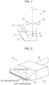
- the nozzle surface portion 23 refers to a region indicated by a dashed line 23 in Fig. 3 .
- the nozzle surface portion 23 refers to a region in the outer surfaces of the upper and lower nozzle members 21 and 22 from the two-dot dashed line A-A' to an end of the gas wiping nozzle 20, wherein the region does not include the outer surfaces that face the hollow 25 of the nozzle.
- the entire gas wiping nozzle 20 including the surface is preferably made of a ceramic.
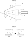
- the reason why at least the surface of the gas wiping nozzle 20 is made of a ceramic is as follows: ceramics do not react with the molten metal, and the molten metal does not adhere to the surface, so that splashes can be easily removed. In addition, increasing the surface roughness of the ceramic as illustrated in Fig. 4 reduces the wettability between the molten metal and the gas wiping nozzle 20 and allows easier removal of splashes of the molten metal, resulting in an advantage of reduced coating thickness unevenness defects.
- the ceramic examples include oxide ceramics, such as alumina, zirconia, magnesium oxide, and chromium oxide; and carbide ceramics, such as silicon carbide, titanium carbide, and chromium carbide.
- carbide ceramics such as silicon carbide, titanium carbide, and chromium carbide.
- nitride ceramics such as silicon nitride, titanium nitride, SiAlON, boron nitride, and boride ceramics, such as zirconium boride, and titanium boride, are preferred, but the ceramic is not limited to these ceramics. It is noted that the exemplified carbide ceramics, nitride ceramics, and boride ceramics may be collectively referred to as non-oxide ceramics.
- the upper nozzle member 21 and the lower nozzle member 22 illustrated in Fig. 3 are also preferably made of a ceramic, which has low wettability to the molten metal.
- a method for forming a ceramic coating when forming the nozzle surface portion 23 from a ceramic film is as described below. Suitable examples of the method include, but are not limited to, vapor-phase CVD (low pressure, plasma), PVD (vacuum deposition, ion plating), thermal spraying of molten materials, or application of solutions, and slurry coating with firing.
- the coating thickness is preferably about 5 to 100 ⁇ m, depending on the type of coating film or the method for forming the coating film.
- the arithmetic mean roughness Ra and the peak count PPI which are measures of surface roughness, of the gas wiping nozzle, need to satisfy Formula (1).
- PPI > c 1 ⁇ Ra + c 2
- the surface roughness and the PPI of the surface (i.e., nozzle surface portion 23) of the gas wiping nozzle 20 are controlled.
- Fig. 4 is a schematic view of wetting properties based on Formula (2). Fig. 4 indicates that, as the surface roughness increases, the contact angle further increases, in other words, the wettability decreases.
- the inventors of the present invention evaluated the wettability by using the arithmetic mean roughness Ra and the peak count PPI, which are measures of surface roughness, instead of r in Formula (2). Specifically, the relationship between wettability and Ra and peak count PPI was investigated on the basis of experimental values obtained from prepared samples having different Ra and PPI. The experimental procedure and conditions are described below.
- the experimental results are shown in Fig. 5 .
- the arithmetic mean roughness Ra was measured in accordance with JIS B 0601-2001.
- the cutoff wavelength in Ra measurement was 0.8 mm.
- the peak count PPI was measured in accordance with SAE J911.
- the peak count level in PPI measurement was 0.635 ⁇ m.
- Fig. 5 shows that the zinc coating weight decreases as the Ra and the PPI increase.
- the arithmetic mean roughness Ra is a measure of the roughness mean height obtained from the roughness curve of the ceramic surface. As the arithmetic mean roughness Ra increases, the roughness amplitude of the ceramic surface increases, and the area ratio of the rough surface to the smooth surface increases.
- the peak count PPI is a measure of the number of peaks per inch in the roughness curve of the ceramic surface. As the peak count PPI increases, the pitch of roughness on the ceramic surface decreases, and the area ratio of the rough surface to the smooth surface increases. Therefore, as a result of the increase in the area ratio of the rough surface to the smooth surface with increasing Ra and PPI, the contact angle increases in accordance with the Wenzel equation, and the zinc coating weight decreases. In other words, the surface may have low wettability. Zinc is used in this experiment, but other metals, such as Al and Cu, can also be used.
- the constants c1 and c2 in Formula (1) vary with the ceramic material used in the nozzle surface portion 23, the constants c1 and c2 need to be determined as needed in the manufacture of the gas wiping nozzle.
- the constants c1 and c2 are calculated in accordance with the following steps.
- the constants c1 and c2 in Formula (1) are mainly correlated with the free energy of formation when the ceramic used in the nozzle surface portion 23 generates an oxide, and determined for each ceramic used in the nozzle surface portion 23.
- the arithmetic mean roughness Ra and the peak count PPI formed on the nozzle surface portion 23 have different characteristics depending on the processing method. It is thus necessary to appropriately control the processing conditions depending on the method for processing the gas wiping nozzle in order to satisfy Formula (1). For example, machining or blasting changes Ra and PPI as described below, and it is thus necessary to appropriately select Ra and PPI in the manufacture of the gas wiping nozzle. Machining:
- the gas wiping nozzles having such a configuration are disposed to face each other in the continuous hot-dip metal coating facility 100 in Fig. 1 . From the gas wiping nozzles, a gas is blown to the steel strip pulled up from the molten metal bath to adjust the coating weight of the molten metal on both sides of the steel strip, whereby the hot-dip metal-coated steel strip can be manufactured continuously.
- a hot-dip galvanized steel strip was manufactured by dipping a steel strip with a sheet thickness of 1.0 mm and a sheet width of 1200 mm in a molten zinc bath at a threading speed of 2.0 m/s in a continuous hot-dip galvanization facility having the basic structure in Fig. 1 .
- the slit of each gas wiping nozzle has a size of 1800 mm in length L1, 20 mm in depth L2, and 1.2 mm in width L3.
- the temperature of the molten zinc bath was 460°C, and the gas temperature T at the ends of the gas wiping nozzles was 80°C.
- the materials of the gas wiping nozzles were SiAlON, alumina, chrome molybdenum steel with an 80- ⁇ m SiAlON coating, and chrome molybdenum steel, which was used as a material having the contact angle of less than 90 degrees.
- the surface processing was blasting.
- the processing conditions in blasting were as follows: silicon carbide or alumina was used as media, and the particle size of the media was defined in JIS R6001.
- the arithmetic mean roughness Ra and the peak count PPI were adjusted by adjusting the projection speed of the media.
- the linear mark occurrence rate was evaluated in Invention Examples and Comparative Examples.
- the linear mark occurrence rate [%] is the ratio of the length of the steel strip determined to have linear mark defects in the inspection process to the length of the steel strip that has passed through under each manufacturing condition. The presence of linear mark defects was visually checked, and steel strips that showed a linear mark occurrence rate of 0.5% or less were determined to be passed.
- the gas wiping nozzle was disassembled and visually inspected for the presence of surface blemishes (nozzle blemishes) on the gas wiping nozzle. The results are shown in Table 1.
- suitable PPI range derived from Ra value refers to a range of peak count PPI that satisfies the relationship of Formula (1) for each arithmetic mean roughness Ra.
- Table 1 Category Material of Nozzle Surface Portion Blasting Ra [ ⁇ m] PPI c1 c2 Suitable PPI Range Derived from Ra Value Linear Mark Occurrence Rate [%] Nozzle Blemishes media material media particle size
- Example 1 SiAION silicon carbide F600 0.25 100 -35 100 over 91 0.25 absent Invention
- Example 2 SiAION silicon carbide F320 0.4 180 -35 100 over 86 0.18 absent Invention
- Example 3 SiAION silicon carbide F240 0.95 240 -35 100 over 67 0.19 absent Invention
- Example 4 SiAION silicon carbide F180 5 90 -35 100 over 81 0.23 absent Invention
- Example 5 chrome molybdenum steel +SiAlON coating (80 ⁇ m) silicon carbide F400 0.37 200 -35 100 over 87 0.28
- Table 1 shows that the linear mark occurrence rates in Invention Examples 1 to 9 were much lower than those in Comparative Examples 1 to 3. No surface blemishes were found on the gas wiping nozzles under the conditions of Invention Examples 1 to 9, whereas blemishes were found in Comparative Example 1. This may be because many linear mark defects occur and the number of gas wiping nozzle cleaning increases.
- the gas wiping nozzle and the method for manufacturing a hot-dip metal-coated steel strip in the present invention it is possible to easily remove molten metal splashes on the gas wiping nozzle and further provide a beautiful steel sheet with no linear mark defects.
- the present invention allows manufacture of a hot-dip metal-coated steel strip at high yield and thus has very high industrial application value.
Landscapes
- Chemical & Material Sciences (AREA)
- Chemical Kinetics & Catalysis (AREA)
- Engineering & Computer Science (AREA)
- Materials Engineering (AREA)
- Mechanical Engineering (AREA)
- Metallurgy (AREA)
- Organic Chemistry (AREA)
- Coating With Molten Metal (AREA)
- Nozzles (AREA)
Abstract
The present invention is directed to a gas wiping nozzle that can easily remove molten metal splashes and can provide a beautiful steel sheet with no linear mark defects, and a method for manufacturing a hot-dip metal-coated steel strip and a gas wiping nozzle.Provided are: a gas wiping nozzle that adjusts the coating weight of a molten metal on the surface of a steel strip pulled up from a molten metal bath, wherein at least the surface of the gas wiping nozzle is made of a ceramic, and the arithmetic mean roughness Ra and the peak count PPI of the gas wiping nozzle satisfy Formula (1); and a method for manufacturing a hot-dip metal-coated steel strip using the gas wiping nozzle. PPI>c1×Ra+c2PPI: peak count (the number of peaks per inch)Ra: arithmetic mean roughness [µm]c1 and c2: constant
Description
- The present invention relates to a gas wiping nozzle used in a hot-dip metal coating line for manufacturing a hot-dip metal-coated steel strip widely used in the fields of building materials, automobiles, and home appliances, or other fields, and to methods for manufacturing the hot-dip metal-coated steel strip and the gas wiping nozzle.
- Hot-dip galvanized steel sheets, a type of hot-dip metal-coated steel strips, have been widely used in the fields of building materials, automobiles, and home appliances, or other fields. In these applications, good appearance is required for hot-dip galvanized steel sheets. Since the appearance after painting is strongly affected by surface defects, such as coating thickness unevenness, blemishes, and adhesion of foreign matter, it is important that hot-dip galvanized steel sheets have no surface defects.
- In a continuous hot-dip metal coating line, as illustrated in
Fig. 1 , a steel strip S annealed in a continuous annealing furnace with a reducing atmosphere is continuously introduced into amolten metal bath 14 in acoating tank 12 through asnout 10. The steel strip S then passes through a sink roll 16 and asupport roll 18 in amolten metal bath 14 and is pulled up from themolten metal bath 14. The coating on the steel strip S is adjusted to a predetermined thickness by usinggas wiping nozzles 20 and 20'. The steel strip S is then cooled and transferred to a subsequent process. Thegas wiping nozzles 20 and 20' are disposed above thecoating tank 12 so as to face each other with the steel strip S therebetween. A gas is blown to both surfaces of the steel strip S from the ejection ports of thegas wiping nozzles 20 and 20'. This gas wiping scrapes off excess molten metal to adjust the coating weight of the steel strip surface and level the molten metal on the steel strip surface in the sheet width direction and the sheet longitudinal direction. To accommodate various strip widths and accommodate deviations in position of the steel strip in the width direction at the time of pulling up the steel strip, thegas wiping nozzles 20 and 20' are typically wider than the steel strip width and extend beyond the edges of the steel strip in the width direction. - Referring to
Fig. 2 as well asFig. 1 , a pair of thegas wiping nozzles 20 and 20' are disposed above thecoating tank 12 so as to face each other with the steel strip S therebetween. A gas is blown to the steel strip S from an ejection port 24 (slit) located at an end of each of thegas wiping nozzles 20 and 20' and extending in the sheet width direction X of the steel strip. The gas is blown to one surface of the steel strip from onegas wiping nozzle 20, and the gas is blown to the other surface of the steel strip from the other gas wiping nozzle 20'. This process scrapes off excess molten metal on both surfaces of the steel strip S to adjust the coating weight and make uniform the coating weight in the sheet width direction X and the sheet longitudinal direction Z. To accommodate various strip widths and accommodate deviations in position of the steel strip in the width direction at the time of pulling up the steel strip, thegas wiping nozzles 20 and 20' are typically wider than the steel strip width and extend beyond the edges of the steel strip in the width direction. - Referring to
Fig. 3 , thewiping nozzle 20 includes anozzle header 26, anupper nozzle member 21, and alower nozzle member 22. Theupper nozzle member 21 and thelower nozzle member 22 are connected to thenozzle header 26. Theupper nozzle member 21 and thelower nozzle member 22 when bonded together vertically define theslit 24 at the end of thewiping nozzle 20 and further define a hollow 25 in communication with theslit 24. In other words, the upper andlower nozzle members slit 24. Theslit 24 forms a gas ejection port and extends in the sheet width direction X. - In such a gas wiping system, droplets (hereinafter referred to as splashes) of molten metal scattered by wiping gas ejection may adhere to the slit. The adhered splashes block the wiping gas and hinder uniform gas ejection in the sheet width direction. As a result, streaky coating thickness unevenness defects called linear marks are generated at positions on the surface of the steel strip corresponding to the positions of the splashes in the slit, resulting in a significantly reduced yield.
-
Patent Literature 1 discloses a technique for easily removing splashes by implanting carbon, nitrogen, boron, silicon, or other ions into the surface of a gas ejection end portion of a gas wiping nozzle in the surface treatment to reduce wettability between splashes and the nozzle. -
Patent Literature 2 discloses a technique for easily removing splashes similarly toPatent Literature 1 by forming the ejection port of a gas wiping nozzle using a carbon material or a ceramic. -
- PTL 1:
Japanese Examined Patent Application Publication No. 6-17560 - PTL 2:
Japanese Unexamined Patent Application Publication No. 2008-190001 - NPL 1: Review of Polarography, Vol. 54, No. 2, (2008)
- It is, however, found that the methods disclosed in
Patent Literature 1 andPatent Literature 2 cannot completely remove splashes, and some of splashes remain. When splashes remain, splashes are further deposited and grow from those splashes, and more noticeable linear marks are thus generated as the operation time increases. To remove adhered splashes through maintenance, it takes a lot of time and effort to remove, and scratches eventually occur on the nozzle surface. - In light of the above circumstances, the present invention is directed to a gas wiping nozzle that can easily remove molten metal splashes and further provide a beautiful steel sheet with no linear mark defects, and methods for manufacturing a hot-dip metal-coated steel strip and a gas wiping nozzle.
- To solve the above problem, a material having low wettability to molten metals is used in a gas wiping nozzle of the present invention. The material having low wettability to molten metals refers to a ceramic.
- It is, however, difficult to completely remove splashes only by using the above measure. The inventors of the present invention have conceived the idea of controlling the roughness of the nozzle surface by using Formula (1) described below in detail as a method for reducing wettability to molten metals.

- PPI: peak count (the number of peaks per inch)
- Ra: arithmetic mean roughness [µm]
- c1 and c2: constant
- The gist of the present invention accomplished on the basis of the above finding is as described below.
- [1] A gas wiping nozzle from which a gas is blown to a steel strip pulled up from a molten metal bath to adjust a coating weight of a molten metal on a surface of the steel strip, wherein at least a surface of a gas wiping nozzle is made of a ceramic, and an arithmetic mean roughness Ra and a peak count PPI, which are measures of surface roughness, of the gas wiping nozzle satisfy Formula (1)

- PPI: peak count (number of peaks per inch)
- Ra: arithmetic mean roughness [µm]
- c1 and c2: constant.
- [2] The gas wiping nozzle according to [1], wherein a material of the gas wiping nozzle is a ceramic.
- [3] A method for manufacturing a hot-dip metal-coated steel strip, the method including: continuously dipping a steel strip in a molten metal bath; and adjusting a coating weight of a molten metal on both sides of the steel strip by blowing a gas to the steel strip from the gas wiping nozzles according to [1] or [2] disposed to face each other with the steel strip, which is pulled up from the molten metal bath, therebetween to continuously manufacture the hot-dip metal-coated steel strip.
- [4] A method for manufacturing the gas wiping nozzle according to [1] or [2], the method including: a step of selecting a material of the gas wiping nozzle or a surface of the gas wiping nozzle; and a step of selecting a processing method and processing conditions for the surface of the gas wiping nozzle, wherein the material and/or the processing method and the processing conditions are selected such that the arithmetic mean roughness Ra and the peak count PPI, which are measures of surface roughness, of the gas wiping nozzle satisfy Formula (1)

- PPI: peak count (number of peaks per inch)
- Ra: arithmetic mean roughness [µm]
- c1 and c2: constant
- Advantageous Effects of Invention.
- The present invention is directed to a gas wiping nozzle that can easily remove molten splashes of molten metal and enables manufacture of beautiful steel sheets with no linear mark defects. This gas wiping nozzle significantly increases the yield in the manufacture of hot-dip metal-coated steel strips and thus has very high industrial application value.
-
- [
Fig. 1] Fig. 1 is a schematic view of the structure of a continuous hot-dip metal coating facility used in an embodiment of the present invention. - [
Fig. 2] Fig. 2 is a schematic perspective view of a gas wiping nozzle of the present invention. - [
Fig. 3] Fig. 3 is a schematic cross-sectional view of the gas wiping nozzle of the present invention perpendicular to a steel strip and a bath surface. - [
Fig. 4] Fig. 4 is a schematic view showing the relationship between surface roughness and wettability based on the Wenzel equation. - [
Fig. 5] Fig. 5 is a graph showing determination of the zinc coating weight in the relationship between arithmetic mean roughness Ra and peak count PPI. - Embodiments of the present invention will be described below with reference to the drawings. The present invention is not limited to embodiments described below. The components in the following embodiments include components that can easily be replaced by those skilled in the art, or substantially the same components.
-
Fig. 1 is a schematic view of the structure of a continuous hot-dip galvanization facility 100 used in an embodiment of the present invention. The continuous hot-dip galvanization facility 100 of the present invention may be a continuous hot-dip galvanization facility known in the related art. -
Fig. 2 is a schematic perspective view of agas wiping nozzle 20 of the present invention. A gas wiping nozzle 20' is not described below, but has the same structure as thegas wiping nozzle 20. Thegas wiping nozzle 20 blows a gas to a steel strip S pulled up from a molten metal bath to adjust the coating weight of a molten metal on the surface of the steel strip. The components of thegas wiping nozzle 20 and the method for assembling the components may be the same as those in the related art. - The present invention is characterized in the material and surface roughness of a
nozzle surface portion 23 of thegas wiping nozzle 20 to be in contact with the molten metal (splashes). In other words, at least the surface (i.e., nozzle surface portion 23) of thegas wiping nozzle 20 needs to be made of a ceramic. Thenozzle surface portion 23 refers to a region indicated by a dashedline 23 inFig. 3 . In other words, thenozzle surface portion 23 refers to a region in the outer surfaces of the upper andlower nozzle members gas wiping nozzle 20, wherein the region does not include the outer surfaces that face the hollow 25 of the nozzle. The entiregas wiping nozzle 20 including the surface is preferably made of a ceramic. - The reason why at least the surface of the
gas wiping nozzle 20 is made of a ceramic is as follows: ceramics do not react with the molten metal, and the molten metal does not adhere to the surface, so that splashes can be easily removed. In addition, increasing the surface roughness of the ceramic as illustrated inFig. 4 reduces the wettability between the molten metal and thegas wiping nozzle 20 and allows easier removal of splashes of the molten metal, resulting in an advantage of reduced coating thickness unevenness defects. - Examples of the ceramic include oxide ceramics, such as alumina, zirconia, magnesium oxide, and chromium oxide; and carbide ceramics, such as silicon carbide, titanium carbide, and chromium carbide. In addition, nitride ceramics, such as silicon nitride, titanium nitride, SiAlON, boron nitride, and boride ceramics, such as zirconium boride, and titanium boride, are preferred, but the ceramic is not limited to these ceramics. It is noted that the exemplified carbide ceramics, nitride ceramics, and boride ceramics may be collectively referred to as non-oxide ceramics. Since the adhesion of splashes is found at the
nozzle surface portion 23, and many splashes are found particularly near the ejection port of the gas wiping nozzle, theupper nozzle member 21 and thelower nozzle member 22 illustrated inFig. 3 are also preferably made of a ceramic, which has low wettability to the molten metal. - A method for forming a ceramic coating when forming the
nozzle surface portion 23 from a ceramic film is as described below. Suitable examples of the method include, but are not limited to, vapor-phase CVD (low pressure, plasma), PVD (vacuum deposition, ion plating), thermal spraying of molten materials, or application of solutions, and slurry coating with firing. To prevent peeling caused by nozzle cleaning, the coating thickness is preferably about 5 to 100 µm, depending on the type of coating film or the method for forming the coating film. - In addition to using such materials, the arithmetic mean roughness Ra and the peak count PPI, which are measures of surface roughness, of the gas wiping nozzle, need to satisfy Formula (1).

- PPI: peak count (the number of peaks per inch)
- Ra: arithmetic mean roughness [µm]
- c1 and c2: constant
- When the arithmetic mean roughness Ra and the peak count PPI do not satisfy Formula (1), splashes cannot be completely removed from the gas wiping nozzle, and linear mark defects occur on the hot-dip galvanized steel sheet. To satisfy Formula (1), it is necessary to control the arithmetic mean roughness Ra and the peak count PPI of the gas wiping nozzle surface to be in contact with splashes.
- The surface roughness and the PPI of the surface (i.e., nozzle surface portion 23) of the
gas wiping nozzle 20 are controlled. - Formula (1) will be described. The concept of wetting is known from the Wenzel equation.
- Formula (2) is the Wenzel equation expressing the relationship between surface roughness and solid surface wettability. Formula (2) is described in
Non Patent Literature 1.
- θw: the apparent contact angle on a rough surface
- θe: the contact angle of a liquid droplet resting on a
- smooth surface
- r: the area ratio of the rough surface to the smooth surface

-
Fig. 4 is a schematic view of wetting properties based on Formula (2).Fig. 4 indicates that, as the surface roughness increases, the contact angle further increases, in other words, the wettability decreases. - The inventors of the present invention evaluated the wettability by using the arithmetic mean roughness Ra and the peak count PPI, which are measures of surface roughness, instead of r in Formula (2). Specifically, the relationship between wettability and Ra and peak count PPI was investigated on the basis of experimental values obtained from prepared samples having different Ra and PPI. The experimental procedure and conditions are described below.
- Experimental procedure:
- Test specimens having different surface roughness were dipped in a molten metal bath for a predetermined time and then naturally cooled to room temperature. A value obtained by dividing a difference in test specimen weight before and after the experiment by the dipped area was recorded as a zinc coating weight [µg/m2] and evaluated on the basis of the following criteria.
- A: failed: zinc coating weight ≥ 5.0 µg/m2
- B: passed: zinc coating weight < 5.0 µg/m2
- Experimental conditions:
- Material of test specimens: SiAlON
- Size of test specimens: 50 mm long × 50 mm wide × 3 mm thick Arithmetic mean roughness Ra of test specimen surface: 0.01 to 5 µm
- Peak count PPI of test specimen surface: 5 to 300
- Type and temperature of molten metal: zinc, 460°C
- Test time: 30 seconds
- The experimental results are shown in
Fig. 5 . The arithmetic mean roughness Ra was measured in accordance with JIS B 0601-2001. The cutoff wavelength in Ra measurement was 0.8 mm. The peak count PPI was measured in accordance with SAE J911. The peak count level in PPI measurement was 0.635 µm.Fig. 5 shows that the zinc coating weight decreases as the Ra and the PPI increase. The arithmetic mean roughness Ra is a measure of the roughness mean height obtained from the roughness curve of the ceramic surface. As the arithmetic mean roughness Ra increases, the roughness amplitude of the ceramic surface increases, and the area ratio of the rough surface to the smooth surface increases. The peak count PPI is a measure of the number of peaks per inch in the roughness curve of the ceramic surface. As the peak count PPI increases, the pitch of roughness on the ceramic surface decreases, and the area ratio of the rough surface to the smooth surface increases. Therefore, as a result of the increase in the area ratio of the rough surface to the smooth surface with increasing Ra and PPI, the contact angle increases in accordance with the Wenzel equation, and the zinc coating weight decreases. In other words, the surface may have low wettability. Zinc is used in this experiment, but other metals, such as Al and Cu, can also be used. - The results in
Fig. 5 indicate that the arithmetic mean roughness Ra and the peak count PPI of the surface of the gas wiping nozzle satisfy Formula (1).
- PPI: peak count (the number of peaks per inch)
- Ra: arithmetic mean roughness [µm]
- c1 and c2: constant
- Since the constants c1 and c2 in Formula (1) vary with the ceramic material used in the
nozzle surface portion 23, the constants c1 and c2 need to be determined as needed in the manufacture of the gas wiping nozzle. The constants c1 and c2 are calculated in accordance with the following steps. - Step 1: Select the material of the nozzle and the component of the molten metal. Since these conditions affect the values of c1 and c2, the constants c1 and c2 are measured whenever the conditions change. The processing method for providing the arithmetic mean roughness Ra and the peak count PPI can be freely selected. Examples of the processing method include, but are not limited to, grinding (a machining method with a grinder) and blasting (a processing method for providing roughness by collision of objects called media to work).
- Step 2: Prepare 10 to 20 types of samples having different Ra and PPI. From the viewpoint of wiping nozzle processing accuracy, the upper limit of Ra is preferably 10 µm or less, and the upper limit of PPI is preferably 500 or less.
- Step 3: Conduct the experiment described above and plot the graph shown in
Fig. 5 . - Step 4: Determine temporary c1' and c2' and draw a line y = c1'x + c2' on the graph.
- Step 5: Calculate the sum (Y) of squares of differences between PPI in the experimental results and y in the graph in
Step 4. (Y = Σ(PPI - y)2) - Step 6: Calculate Y by changing the values of c1' and c2' five times, and use c1' and c2' at the smallest Y as c1 and c2. It is noted that each constant is calculated by multiple regression.
- The constants c1 and c2 in Formula (1) are mainly correlated with the free energy of formation when the ceramic used in the
nozzle surface portion 23 generates an oxide, and determined for each ceramic used in thenozzle surface portion 23. - The arithmetic mean roughness Ra and the peak count PPI formed on the
nozzle surface portion 23 have different characteristics depending on the processing method. It is thus necessary to appropriately control the processing conditions depending on the method for processing the gas wiping nozzle in order to satisfy Formula (1). For example, machining or blasting changes Ra and PPI as described below, and it is thus necessary to appropriately select Ra and PPI in the manufacture of the gas wiping nozzle. Machining: - As the machining speed increases, the PPI increases with Ra constant.
- As the radius of the edge of the machining blade increases, the Ra decreases.
- As the Ra of the machining blade decreases, the PPI increases.
- As the particle size of the media decreases, the Ra and the PPI decrease.
- As the media are made of a softer material, the Ra and the PPI decrease.
- The gas wiping nozzles having such a configuration are disposed to face each other in the continuous hot-dip
metal coating facility 100 inFig. 1 . From the gas wiping nozzles, a gas is blown to the steel strip pulled up from the molten metal bath to adjust the coating weight of the molten metal on both sides of the steel strip, whereby the hot-dip metal-coated steel strip can be manufactured continuously. - A hot-dip galvanized steel strip was manufactured by dipping a steel strip with a sheet thickness of 1.0 mm and a sheet width of 1200 mm in a molten zinc bath at a threading speed of 2.0 m/s in a continuous hot-dip galvanization facility having the basic structure in
Fig. 1 . The slit of each gas wiping nozzle has a size of 1800 mm in length L1, 20 mm in depth L2, and 1.2 mm in width L3. The temperature of the molten zinc bath was 460°C, and the gas temperature T at the ends of the gas wiping nozzles was 80°C. - The materials of the gas wiping nozzles were SiAlON, alumina, chrome molybdenum steel with an 80-µm SiAlON coating, and chrome molybdenum steel, which was used as a material having the contact angle of less than 90 degrees. The surface processing was blasting. The processing conditions in blasting were as follows: silicon carbide or alumina was used as media, and the particle size of the media was defined in JIS R6001. The arithmetic mean roughness Ra and the peak count PPI were adjusted by adjusting the projection speed of the media. The constants in Formula (1) were determined in an offline pre-test and found to be c1 = -35 and c2 = 100 for SiAlON. The constants for alumina were found to be c1 = -28 and c2 = 170. The constants for chrome molybdenum steel with an 80-µm SiAlON coating were found to be c1 = -35 and c2 = 100, which were the same as for SiAlON.
- The linear mark occurrence rate was evaluated in Invention Examples and Comparative Examples. The linear mark occurrence rate [%] is the ratio of the length of the steel strip determined to have linear mark defects in the inspection process to the length of the steel strip that has passed through under each manufacturing condition. The presence of linear mark defects was visually checked, and steel strips that showed a linear mark occurrence rate of 0.5% or less were determined to be passed. After manufacturing completion, the gas wiping nozzle was disassembled and visually inspected for the presence of surface blemishes (nozzle blemishes) on the gas wiping nozzle. The results are shown in Table 1. The "suitable PPI range derived from Ra value" refers to a range of peak count PPI that satisfies the relationship of Formula (1) for each arithmetic mean roughness Ra.
[Table 1] Category Material of Nozzle Surface Portion Blasting Ra [µm] PPI c1 c2 Suitable PPI Range Derived from Ra Value Linear Mark Occurrence Rate [%] Nozzle Blemishes media material media particle size Invention Example 1 SiAION silicon carbide F600 0.25 100 -35 100 over 91 0.25 absent Invention Example 2 SiAION silicon carbide F320 0.4 180 -35 100 over 86 0.18 absent Invention Example 3 SiAION silicon carbide F240 0.95 240 -35 100 over 67 0.19 absent Invention Example 4 SiAION silicon carbide F180 5 90 -35 100 over 81 0.23 absent Invention Example 5 chrome molybdenum steel +SiAlON coating (80 µm) silicon carbide F400 0.37 200 -35 100 over 87 0.28 absent Invention Example 6 alumina alumina F800 0.21 210 -28 170 over 164 0.27 absent Invention Example 7 alumina alumina F280 0.37 195 -28 170 over 160 0.21 absent Invention Example 8 alumina alumina F230 0.9 160 -28 170 over 145 0.19 absent Invention Example 9 alumina alumina F120 4.7 70 -28 170 over 38 0.16 absent Comparative Example 1 chrome molybdenum steel silicon carbide F180 0.4 180 - - - 2.67 present Comparative Example 2 SiAION silicon carbide F1000 0.02 5 -35 100 over 99 1.82 absent Comparative Example 3 alumina alumina F1200 0.05 120 -28 170 over 169 1.93 absent - Table 1 shows that the linear mark occurrence rates in Invention Examples 1 to 9 were much lower than those in Comparative Examples 1 to 3. No surface blemishes were found on the gas wiping nozzles under the conditions of Invention Examples 1 to 9, whereas blemishes were found in Comparative Example 1. This may be because many linear mark defects occur and the number of gas wiping nozzle cleaning increases.
- According to the gas wiping nozzle and the method for manufacturing a hot-dip metal-coated steel strip in the present invention, it is possible to easily remove molten metal splashes on the gas wiping nozzle and further provide a beautiful steel sheet with no linear mark defects. The present invention allows manufacture of a hot-dip metal-coated steel strip at high yield and thus has very high industrial application value.
-
- 100
- Continuous hot-dip metal coating facility
- 10
- Snout
- 12
- Coating tank
- 14
- Molten metal bath
- 16
- Sink roll
- 18
- Support roll
- 20, 20'
- Gas wiping nozzle
- 21
- Upper nozzle member
- 22
- Lower nozzle member
- 23
- Nozzle surface portion
- 24
- Ejection port (slit)
- 25
- Hollow
- 26
- Nozzle header
- 27
- Gas supply path
- 28
- Gas supply pipe
- 29
- molten metal (splash)
- 30
- Material
- θe, θw
- Contact angle
- L1
- Slit length
- L2
- Slit depth
- L3
- Slit width
Claims (4)
- A gas wiping nozzle from which a gas is blown to a steel strip pulled up from a molten metal bath to adjust a coating weight of a molten metal on a surface of the steel strip, wherein at least a surface of a gas wiping nozzle is made of a ceramic, and an arithmetic mean roughness Ra and a peak count PPI, which are measures of surface roughness, of the gas wiping nozzle satisfy Formula (1)
 PPI: peak count (number of peaks per inch)Ra: arithmetic mean roughness [µm]c1 and c2: constant.
 - The gas wiping nozzle according to Claim 1, wherein a material of the gas wiping nozzle is a ceramic.
- A method for manufacturing a hot-dip metal-coated steel strip, the method comprising: continuously dipping a steel strip in a molten metal bath; and adjusting a coating weight of a molten metal on both sides of the steel strip by blowing a gas to the steel strip from the gas wiping nozzles according to Claim 1 or 2 disposed to face each other with the steel strip, which is pulled up from the molten metal bath, therebetween to continuously manufacture the hot-dip metal-coated steel strip.
- A method for manufacturing the gas wiping nozzle according to Claim 1 or 2, the method comprising:a step of selecting a material of the gas wiping nozzle or a surface of the gas wiping nozzle; anda step of selecting a processing method and processing conditions for the surface of the gas wiping nozzle,wherein the material and/or the processing method and the processing conditions are selected such that the arithmetic mean roughness Ra and the peak count PPI, which are measures of surface roughness, of the gas wiping nozzle satisfy Formula (1)
 PPI: peak count (number of peaks per inch)Ra: arithmetic mean roughness [µm]c1 and c2: constant.
Applications Claiming Priority (2)
| Application Number | Priority Date | Filing Date | Title |
|---|---|---|---|
| JP2021200565 | 2021-12-10 | ||
| PCT/JP2022/037767 WO2023105910A1 (en) | 2021-12-10 | 2022-10-11 | Gas wiping nozzle and method for manufacturing hot dip metal-plated steel strip and gas wiping nozzle |
Publications (2)
| Publication Number | Publication Date |
|---|---|
| EP4407064A4 EP4407064A4 (en) | 2024-07-31 |
| EP4407064A1 true EP4407064A1 (en) | 2024-07-31 |
Family
ID=86730172
Family Applications (1)
| Application Number | Title | Priority Date | Filing Date |
|---|---|---|---|
| EP22903844.3A Pending EP4407064A1 (en) | 2021-12-10 | 2022-10-11 | Gas wiping nozzle and method for manufacturing hot dip metal-plated steel strip and gas wiping nozzle |
Country Status (8)
| Country | Link |
|---|---|
| US (1) | US20250034691A1 (en) |
| EP (1) | EP4407064A1 (en) |
| JP (1) | JP7435898B2 (en) |
| KR (1) | KR20240096717A (en) |
| CN (1) | CN118355144A (en) |
| AU (1) | AU2022407620B2 (en) |
| MX (1) | MX2024006893A (en) |
| WO (1) | WO2023105910A1 (en) |
Families Citing this family (2)
| Publication number | Priority date | Publication date | Assignee | Title |
|---|---|---|---|---|
| JP7800725B2 (en) * | 2023-08-29 | 2026-01-16 | Jfeスチール株式会社 | Gas injection device, hot-dip plated metal strip manufacturing equipment, hot-dip plated metal strip manufacturing method, and gas injection device cleaning method |
| WO2025047021A1 (en) * | 2023-08-29 | 2025-03-06 | Jfeスチール株式会社 | Gas injection device, facility for manufacturing hot-dip plated metal strip, method for manufacturing hot-dip plated metal strip, and method for cleaning gas injection device |
Family Cites Families (5)
| Publication number | Priority date | Publication date | Assignee | Title |
|---|---|---|---|---|
| JPH0617560B2 (en) | 1986-06-19 | 1994-03-09 | 新日本製鐵株式会社 | Gas wiping nozzle for surface treatment of metal strip |
| JPH0617560A (en) | 1992-06-30 | 1994-01-25 | Taisei Corp | Seismic isolation structure for large span buildings |
| JPH0827555A (en) * | 1994-07-12 | 1996-01-30 | Nippon Steel Corp | Slit nozzle for hot metal plating |
| KR20070117405A (en) * | 2006-06-08 | 2007-12-12 | 주식회사 포스코 | Gas wiping device for hot dip galvanizing |
| JP2008190001A (en) | 2007-02-06 | 2008-08-21 | Mitsubishi-Hitachi Metals Machinery Inc | Wiping nozzle |
-
2022
- 2022-10-11 CN CN202280079007.XA patent/CN118355144A/en active Pending
- 2022-10-11 MX MX2024006893A patent/MX2024006893A/en unknown
- 2022-10-11 WO PCT/JP2022/037767 patent/WO2023105910A1/en not_active Ceased
- 2022-10-11 JP JP2023506161A patent/JP7435898B2/en active Active
- 2022-10-11 US US18/716,260 patent/US20250034691A1/en active Pending
- 2022-10-11 AU AU2022407620A patent/AU2022407620B2/en active Active
- 2022-10-11 EP EP22903844.3A patent/EP4407064A1/en active Pending
- 2022-10-11 KR KR1020247018748A patent/KR20240096717A/en active Pending
Also Published As
| Publication number | Publication date |
|---|---|
| MX2024006893A (en) | 2024-07-10 |
| JP7435898B2 (en) | 2024-02-21 |
| JPWO2023105910A1 (en) | 2023-06-15 |
| EP4407064A4 (en) | 2024-07-31 |
| AU2022407620B2 (en) | 2025-08-28 |
| AU2022407620A1 (en) | 2024-05-09 |
| CN118355144A (en) | 2024-07-16 |
| WO2023105910A1 (en) | 2023-06-15 |
| KR20240096717A (en) | 2024-06-26 |
| US20250034691A1 (en) | 2025-01-30 |
Similar Documents
| Publication | Publication Date | Title |
|---|---|---|
| US8053058B2 (en) | Spray-coated member having an excellent resistance to plasma erosion and method of producing the same | |
| US20250034691A1 (en) | Gas wiping nozzle and methods for manufacturing hot-dip metal-coated steel strip and gas wiping nozzle | |
| KR101722009B1 (en) | Coated cutting tool | |
| US20070072008A1 (en) | Metal strip product | |
| JP2009530500A (en) | Edge coating in continuous deposition line | |
| KR101757489B1 (en) | Surface coated cutting tool with excellent chip resistance | |
| JP7636492B2 (en) | Coated Cutting Tools | |
| US20070224350A1 (en) | Edge coating in continuous deposition line | |
| EP3943222A1 (en) | Coated cutting tool | |
| CN107532271B (en) | Manufacturing device and manufacturing method of hot-dip metal strip | |
| CN112041467A (en) | Method for manufacturing coated steel components from flat steel products, flat steel products and steel components | |
| US11566305B2 (en) | Titanium plate | |
| KR101858862B1 (en) | Alloy plated steel having excellent cracking resistance, and method for manufacturing the same | |
| US11655532B2 (en) | Gas wiping nozzle and method of manufacturing hot-dip metal coated metal strip | |
| JP5596334B2 (en) | Roll for hot metal plating bath | |
| JP7800726B2 (en) | Gas injection device, hot-dip plated metal strip manufacturing equipment, hot-dip plated metal strip manufacturing method, and gas injection device cleaning method | |
| KR100439411B1 (en) | A spray coating method for hearth roll | |
| KR20010060423A (en) | a method of manufacturing a hot dip galvanized steel sheets with excellent surface appearance | |
| JP7800725B2 (en) | Gas injection device, hot-dip plated metal strip manufacturing equipment, hot-dip plated metal strip manufacturing method, and gas injection device cleaning method | |
| EP4368741A1 (en) | Molten metal-plated steel strip production method | |
| KR20070117405A (en) | Gas wiping device for hot dip galvanizing | |
| JP2002275613A (en) | Method and system for controlling deposition amount of plating | |
| US11976350B2 (en) | Covering member and method for manufacturing the same | |
| JP2026022013A (en) | Gas wiping nozzle, gas injection device, and method for manufacturing hot-dip metal coated steel sheet | |
| JP2025148667A (en) | Cleaning tool for gas injection device and cleaning method for gas injection device |
Legal Events
| Date | Code | Title | Description |
|---|---|---|---|
| STAA | Information on the status of an ep patent application or granted ep patent |
Free format text: STATUS: THE INTERNATIONAL PUBLICATION HAS BEEN MADE |
|
| PUAI | Public reference made under article 153(3) epc to a published international application that has entered the european phase |
Free format text: ORIGINAL CODE: 0009012 |
|
| STAA | Information on the status of an ep patent application or granted ep patent |
Free format text: STATUS: REQUEST FOR EXAMINATION WAS MADE |
|
| 17P | Request for examination filed |
Effective date: 20240422 |
|
| A4 | Supplementary search report drawn up and despatched |
Effective date: 20240510 |
|
| AK | Designated contracting states |
Kind code of ref document: A1 Designated state(s): AL AT BE BG CH CY CZ DE DK EE ES FI FR GB GR HR HU IE IS IT LI LT LU LV MC ME MK MT NL NO PL PT RO RS SE SI SK SM TR |
|
| DAV | Request for validation of the european patent (deleted) | ||
| DAX | Request for extension of the european patent (deleted) |