EP4406858A1 - Aircraft light, aircraft comprising an aircraft light, and method of manufacturing an aircraft light - Google Patents
Aircraft light, aircraft comprising an aircraft light, and method of manufacturing an aircraft light Download PDFInfo
- Publication number
- EP4406858A1 EP4406858A1 EP23153170.8A EP23153170A EP4406858A1 EP 4406858 A1 EP4406858 A1 EP 4406858A1 EP 23153170 A EP23153170 A EP 23153170A EP 4406858 A1 EP4406858 A1 EP 4406858A1
- Authority
- EP
- European Patent Office
- Prior art keywords
- light
- converting material
- aircraft
- emitting semiconductor
- transmissive layer
- Prior art date
- Legal status (The legal status is an assumption and is not a legal conclusion. Google has not performed a legal analysis and makes no representation as to the accuracy of the status listed.)
- Granted
Links
Images


Classifications
-
- B—PERFORMING OPERATIONS; TRANSPORTING
- B64—AIRCRAFT; AVIATION; COSMONAUTICS
- B64D—EQUIPMENT FOR FITTING IN OR TO AIRCRAFT; FLIGHT SUITS; PARACHUTES; ARRANGEMENT OR MOUNTING OF POWER PLANTS OR PROPULSION TRANSMISSIONS IN AIRCRAFT
- B64D47/00—Equipment not otherwise provided for
- B64D47/02—Arrangements or adaptations of signal or lighting devices
-
- F—MECHANICAL ENGINEERING; LIGHTING; HEATING; WEAPONS; BLASTING
- F21—LIGHTING
- F21V—FUNCTIONAL FEATURES OR DETAILS OF LIGHTING DEVICES OR SYSTEMS THEREOF; STRUCTURAL COMBINATIONS OF LIGHTING DEVICES WITH OTHER ARTICLES, NOT OTHERWISE PROVIDED FOR
- F21V9/00—Elements for modifying spectral properties, polarisation or intensity of the light emitted, e.g. filters
- F21V9/40—Elements for modifying spectral properties, polarisation or intensity of the light emitted, e.g. filters with provision for controlling spectral properties, e.g. colour, or intensity
-
- B—PERFORMING OPERATIONS; TRANSPORTING
- B64—AIRCRAFT; AVIATION; COSMONAUTICS
- B64D—EQUIPMENT FOR FITTING IN OR TO AIRCRAFT; FLIGHT SUITS; PARACHUTES; ARRANGEMENT OR MOUNTING OF POWER PLANTS OR PROPULSION TRANSMISSIONS IN AIRCRAFT
- B64D11/00—Passenger or crew accommodation; Flight-deck installations not otherwise provided for
-
- B—PERFORMING OPERATIONS; TRANSPORTING
- B64—AIRCRAFT; AVIATION; COSMONAUTICS
- B64D—EQUIPMENT FOR FITTING IN OR TO AIRCRAFT; FLIGHT SUITS; PARACHUTES; ARRANGEMENT OR MOUNTING OF POWER PLANTS OR PROPULSION TRANSMISSIONS IN AIRCRAFT
- B64D47/00—Equipment not otherwise provided for
- B64D47/02—Arrangements or adaptations of signal or lighting devices
- B64D47/06—Arrangements or adaptations of signal or lighting devices for indicating aircraft presence
-
- F—MECHANICAL ENGINEERING; LIGHTING; HEATING; WEAPONS; BLASTING
- F21—LIGHTING
- F21V—FUNCTIONAL FEATURES OR DETAILS OF LIGHTING DEVICES OR SYSTEMS THEREOF; STRUCTURAL COMBINATIONS OF LIGHTING DEVICES WITH OTHER ARTICLES, NOT OTHERWISE PROVIDED FOR
- F21V5/00—Refractors for light sources
- F21V5/04—Refractors for light sources of lens shape
-
- B—PERFORMING OPERATIONS; TRANSPORTING
- B64—AIRCRAFT; AVIATION; COSMONAUTICS
- B64D—EQUIPMENT FOR FITTING IN OR TO AIRCRAFT; FLIGHT SUITS; PARACHUTES; ARRANGEMENT OR MOUNTING OF POWER PLANTS OR PROPULSION TRANSMISSIONS IN AIRCRAFT
- B64D11/00—Passenger or crew accommodation; Flight-deck installations not otherwise provided for
- B64D2011/0038—Illumination systems for cabins as a whole
-
- B—PERFORMING OPERATIONS; TRANSPORTING
- B64—AIRCRAFT; AVIATION; COSMONAUTICS
- B64D—EQUIPMENT FOR FITTING IN OR TO AIRCRAFT; FLIGHT SUITS; PARACHUTES; ARRANGEMENT OR MOUNTING OF POWER PLANTS OR PROPULSION TRANSMISSIONS IN AIRCRAFT
- B64D11/00—Passenger or crew accommodation; Flight-deck installations not otherwise provided for
- B64D2011/0053—Cabin passenger reading lights
-
- B—PERFORMING OPERATIONS; TRANSPORTING
- B64—AIRCRAFT; AVIATION; COSMONAUTICS
- B64D—EQUIPMENT FOR FITTING IN OR TO AIRCRAFT; FLIGHT SUITS; PARACHUTES; ARRANGEMENT OR MOUNTING OF POWER PLANTS OR PROPULSION TRANSMISSIONS IN AIRCRAFT
- B64D2203/00—Aircraft or airfield lights using LEDs
Definitions
- the present invention relates to aircraft lighting.
- the present invention relates to an aircraft light, further in particular to an aircraft light providing a white light output.
- the present invention further relates to an aircraft comprising such an aircraft light, and to a method of manufacturing an aircraft light providing a white light output.
- Exterior aircraft lights are employed for a wide variety of different purposes, such as for allowing the passengers and/or air crew to view the outside, for passive visibility, for signaling purposes, etc.
- Examples of such exterior light units are navigation lights, also referred to as position lights, red-flashing beacon lights, white strobe anti-collision lights, wing scan lights, take-off lights, landing lights, taxi lights, runway turn-off lights, etc.
- Passenger aircraft such as commercial air planes, comprising a passenger cabin with passenger seats, are usually equipped with general passenger cabin lights for illuminating the passenger cabin and washroom lights for illuminating washrooms.
- passenger aircraft are usually further equipped with a plurality of individually switchable passenger reading lights and a plurality of individually switchable signal lights. All of these lights are examples of interior aircraft lights.
- LEDs light emitting semiconductor diodes
- Commercially available LEDs do often not provide the desired spectrum of white light, such as aviation white light. This is in particular the case when the light emission surfaces of the LEDs are overmolded with an optically dense material, such as silicone.
- an aircraft light that includes a semiconductor light source and that is capable to emit light having a desired kind of white light output.
- Exemplary embodiments of the invention include an aircraft light, providing a white light output, which has a light source, wherein the light source comprises: a light emitting semiconductor for emitting light having an initial light spectrum; a first light converting material, which is arranged over the light emitting semiconductor, and a light transmissive layer, which covers the first light converting material.
- the first light converting material is configured such that a first portion of the light, which is emitted by the light emitting semiconductor, is shifted towards longer wavelengths by the first light converting material.
- the aircraft light further comprises a second light converting material, which is arranged over the light transmissive layer of the light source, in particular on the side of the light transmissive layer that is opposite to the first light converting material; and a lens element, which is arranged over the second light converting material, so that light exiting the lens element forms at least a portion of the white light output of the aircraft light.
- the second light converting material is configured such that a second portion of the light, which is emitted by the light emitting semiconductor, is shifted towards longer wavelengths by the second light converting material.
- the initial light spectrum may comprise light having only a single wavelength, or light having a plurality of wavelengths.
- Exemplary embodiments of the invention also include a method of manufacturing an aircraft light, which provides a white light output in operation, wherein the method comprises:
- the spectrum of a portion of the light, which is emitted by the light emitting semiconductor is shifted towards longer wavelengths, i.e. towards the red side of the spectrum, by the first light converting material, which is provided as part of the light source.
- This effect may, however, not be sufficient for generating the desired white light output of the aircraft light, i.e. a white light output having the desired chromaticity.
- the chromaticity may, for example, be represented in an International Commission on Illumination (CIE) 1931 chromaticity diagram.
- the spectrum shifting effect caused by the first light converting material may in particular not be sufficient in cases where a light output surface of the light source is covered with an optically dense material, such as silicone, because the optically dense material reduces the occurrence of internal reflection at said light output surface and, therefore, reduces the instances of wavelength shifting within the first light converting material.
- an optically dense material such as silicone
- the second light converting material when arranged over the light transmissive layer of the light source, causes additional instances of wavelength shifting and, therefore, causes a further shift of the spectrum of a portion of the light, which is emitted by the light emitting semiconductor.
- the second light converting material may in particular cause an additional shift of the spectrum of a portion of light that is emitted by the light emitting semiconductor and that has not been shifted by the first light converting material.
- the above described effect of the second light converting material results in an additional shift of the spectrum of the light emitted by the aircraft light towards longer wavelengths.
- the combination of the first and second light converting materials may cause a shift of the spectrum of the emitted light that results in the aircraft light emitting a desired shade of white light.
- the aircraft light may thus emit a white light output having a spectrum that is within or sufficiently close to aviation white light, as it is defined in section 25.1397 of the FAR.
- the spectrum of the light output may be shifted even further, i.e. beyond the spectrum of aviation white light, in order to output "warm” white light.
- Such "warm” white light may be perceived as more pleasant by the human eye.
- Each of the first and second light converting materials may be configured for emitting light having a second spectrum, when it is excited by light having a first spectrum, which is emitted by the light emitting semiconductor.
- the second spectrum may be shifted towards longer wavelengths with respect to the first spectrum.
- the first light converting material and/or the second light converting material may comprise Cerium doped Yttrium Aluminium Garnet and/or a nitridosilicate based light converting material. Such materials have been found to be very effective in causing the desired shift of the spectrum of incoming light towards longer wavelengths.
- light converting materials are often referred to as phosphors. Accordingly, it can be said that the light source of the aircraft light, as described herein, comprises a first phosphor and that a second phosphor is arranged over the light transmissive layer of the light source.
- the terms light converting material and phosphor / phosphor material may be used interchangeably in the context of the present description.
- the first light converting material and the second light converting material may have the same wavelength shifting characteristics.
- the first light converting material and the second light converting material may comprise the same optically active substance, such as Cerium doped Yttrium Aluminium Garnet and/or a nitridosilicate based light converting material.
- the second light converting material comprises an optically active substance, such as Cerium doped Yttrium Aluminium Garnet and/or a nitridosilicate based light converting material, that is embedded into a carrier material.
- an optically active substance such as Cerium doped Yttrium Aluminium Garnet and/or a nitridosilicate based light converting material, that is embedded into a carrier material. The may allow for conveniently, efficiently, and reliably applying and fixing the optically active substance to the light transmissive layer of the light source.
- the carrier material includes a silicone matrix or an epoxy matrix or a polyurethane matrix.
- Such matrix materials have been found as well-suited for applying and permanently fixing the optically active substance to the light transmissive layer of the light source.
- the initial light spectrum i.e. the spectrum of the light, which is emitted by the light emitting semiconductor
- the initial light spectrum may be blue or blueish, i.e. the wavelengths of the light, emitted by the light emitting semiconductor, may predominantly be in a range of between 450 nm and 500 nm.
- Blue light is well suited for being converted other light color(s) by appropriate light converting materials, with the remaining blue light and the other light color(s) then jointly providing white light.
- the light emitting semiconductor includes at least one of Indium Gallium Nitride (InGaN), Zinc Selenid (ZnSe), and Silicone Carbide (SiC). These materials have been found as well suited for manufacturing light emitting semiconductors that emit blue / blueish light.
- InGaN Indium Gallium Nitride
- ZnSe Zinc Selenid
- SiC Silicone Carbide
- the white light output may be aviation white light, i.e. white light which fulfills the requirements as defined in section 25.1397 of the FAR.
- the second light converting material is provided as a light converting layer, which is arranged on the light transmissive layer of the light source, in particular on the side of the light transmissive layer facing away from the first light converting material.
- the light transmissive layer may be sandwiched between the first and second light converting materials.
- the light transmissive layer may in particular be coated with the second light converting material.
- the second light converting material has a thickness of less than 1 mm
- the second light converting material may in particular have a thickness of less than 0.5 mm.
- the second light converting material may have a thickness of at least 0.1 mm.
- a thickness of less than 1 mm, in particular a thickness of less than 0.5 mm, has been found as resulting in a suitable shift of the spectrum of the light, emitted by the light source, towards longer wavelengths, without unduly reducing the intensity of the light emitted by the light source.
- the light transmissive layer is a transparent layer
- the light transmissive layer may in particular be a transparent layer that is made from glass or sapphire.
- sapphire is commonly used in the field of semiconductor light sources for the upper light transmissive layer.
- sapphire may refer to artificial sapphire glass.
- the light transmissive layer may be made from any suitable material, such as from the mentioned glass or sapphire, such as from silicone, or from other suitable materials that are able to sustain the operating temperature of the semiconductor light source.
- the lens element is a silicone based lens element.
- a silicone based lens element has been found as being well-suited for reliably protecting the light source and the second light converting material from adverse external influences, such as dirt, water, moisture and mechanical impacts. Also, silicone has been found to have good optical properties for forming the lens element.
- the lens element may be overmolded over the light source and the second light converting material for covering the light source and the second light converting material.
- arranging the lens element over the second light converting material may include overmolding the lens element over the light source and the second light converting material.
- the lens element may be provided as a hard lens element, having a low elasticity, or as a soft lens element, which has some elasticity for absorbing the forces of mechanical impact by elastic deformation.
- the light emitting semiconductor, the first light converting material, and the light transmissive layer are provided as an integrated light source structure, in particular as an integrated light emitting diode (LED).
- the LED may, in particular, be an off the shelf product, which may be produced in large numbers at lows costs. Such an off the shelf LED may be modified, in order to emit light having a desired spectrum of white light, by applying the second light converting material to the light transmissive layer of the LED.
- the aircraft light comprises a plurality of light sources, wherein each of the plurality of light sources has a light emitting semiconductor, a first light converting material, and a light transmissive layer, respectively.
- Each of the plurality of light sources may have any of the features, alone or in combination, as has been described before.
- each of the plurality of light sources may be provided with a respective second light converting material and a respective lens element.
- a common lens element may be arranged over a plurality of light sources, wherein each light source is provided with a respective second light converting material.
- the common lens element may, for example, be configured for forming a highly targeted light output of the aircraft light.
- the highly targeted light output may be used for employing the aircraft light as an aircraft headlight, such as a landing light or a take-off light.
- the aircraft light is an exterior aircraft light, i.e. an aircraft light which is configured for emitting light from an aircraft into an outside environment of the aircraft.
- the exterior aircraft light may in particular be one of a take-off light, a landing light, a taxi light, a runway turn-off light, a navigation light, in particular a white navigation light, and a white strobe anti-collision light.
- the exterior aircraft light may also be a multi-functional light, which combines the functionalities of at least two of a take-off light, a landing light, a taxi light, a runway turn-off light, a navigation light, in particular a white navigation light, and a white strobe anti-collision light.
- the aircraft light is an interior aircraft light, which is provided within an aircraft for illuminating an area or space within the aircraft.
- the interior aircraft light may in particular be a general cabin illumination light for illuminating at least a potion of the cabin of an aircraft, a personal passenger reading light, a washroom illumination light for illuminating a washroom of an aircraft, or a signal light.
- the signal light may, for example, be a non-smoking light, a fasten-your-seatbelt light or an indicator light which lights up in case a request for the cabin service personnel has been triggered.
- An interior aircraft light according to an exemplary embodiment of the invention may also be used for indicating an exit, an emergency exit and/or the shortest way to the nearest exit and/or emergency exit.
- Exemplary embodiments of the invention further include an aircraft, in particular an airplane or a helicopter, comprising at least one aircraft light according to an exemplary embodiment of the invention.
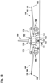
- Figures 1A and 1B jointly referred to as Figure 1 herein, show an aircraft 102, in particular an airplane, comprising a fuselage 130, which houses a cockpit 202 and a passenger cabin 204, and two wings 140, extending from the fuselage 130.
- Two horizontal stabilisers 170 and a vertical stabiliser 180 extend from a rear portion of the fuselage 130.
- An engine 150 is mounted to each of the wings 140, respectively.
- the aircraft 102 is shown in a top view in Figure 1A and shown in a front view in Figure 1B .
- the aircraft 102 of Figure 1 is equipped with a wide variety of exterior lights.
- the aircraft 102 is equipped with three navigation lights 106, two logo lights 108, two wing scan lights 110, two engine scan lights 112, two runway turn-off lights 114, two cargo loading lights 116, three white anti-collision strobe lights 118, two red-flashing anti-collision beacon lights 120, a landing light 122, a take-off light 124 and a taxi light 126. It is pointed out that these kinds of lights and their numbers are exemplary only and that the aircraft 102 may be equipped with additional lights that are not shown.
- the three navigation lights 106 are positioned in the left and right wing tips 142 as well as at the the tail 160 of the aircraft 102. In normal flight conditions, each one of the navigation lights 106 emits light in one of the colors green, red and white, thus indicating to the aircraft environment if they are looking at the port side, starboard side or tail side of the aircraft. The navigation lights 106 are normally on during all phases of the flight and in all flight conditions.
- the logo lights 108 are directed to the vertical stabiliser 180 of the aircraft 102 and are provided for illuminating the same, in particular for illuminating the logo commonly provided on the vertical stabiliser 180.
- the logo lights 108 are normally switched on for the entire duration of the flight during night flights. It is also possible that the logo lights are only used during taxiing on the airport and are normally switched off during the flight.
- the wing scan lights 110 and the engine scan lights 112 are positioned on the left and right sides of the fuselage 130, in front of the roots 144 of the wings 140 of the aircraft 102.
- the wing scan lights 110 and the engine scan lights 112 are normally off during the flight and may be switched on periodically or upon reasonable cause by the pilots or by the aircrew, in order to check the wings 140 and the engines 150 of the aircraft 102.
- the runway turn-off lights 114 are positioned in the roots 144 of the wings 140.
- the runway turn-off lights 114 are directed forwards and are normally switched off during the flight and switched on during taxiing, at least at night.
- the cargo loading lights 116 are positioned on the left and right sides of the fuselage 130, behind the wings 140 and in front of the tail structure of the aircraft 102. They are normally switched off during the flight of the aircraft 102.
- the white anti-collision strobe lights 118 are positioned in the left and right wing tips 142 as well as at the tail 160 of the aircraft 102.
- the white anti-collision strobe lights 118 emit respective sequences of white light flashes during normal operation of the aircraft 102. It is also possible that the white anti-collision strobe lights 118 are only operated during night and in bad weather conditions.
- the red-flashing anti-collision beacon lights 120 are positioned on the top and the bottom of the fuselage 130 of the aircraft 102. They are arranged at the height of the wings in the longitudinal direction of the aircraft 102. While one of the red-flashing anti-collision beacon lights 120 is disposed on the top of the fuselage 130, the other one of the red-flashing anti-collision beacon lights 120 is disposed on the bottom of the fuselage 130 and is therefore shown in phantom in Figure 1A .
- the red-flashing anti-collision beacon lights 120 are normally switched on during taxiing and during take-off and landing. Their output is perceived as a sequence of red light flashes in a given viewing direction.
- the runway turn-off lights 114 are located in the wings 140, in particular in the roots 144 of the wings 140, and the landing light 122, the take-off light 124 and the taxi light 126 are mounted to the front gear 135 of the aircraft 102.
- the front gear 135 is stored within the fuselage 130 of the aircraft 102 during flight, and it is deployed during landing, taxiing and take off.
- the runway turn-off lights 114 may be mounted to the front gear 135 and/or at least one of the landing light 122, the take-off light 124 and the taxi light 126 may be installed in the wings 140, in particular in the roots 144 of the wings 140, of the aircraft 102.
- the aircraft 102 may also comprise a multi-functional light, which combines the functionalities of at least two of the landing light 122, the take-off light 124, the taxi light 126, the runway turn-off lights 114, a navigation light 106, and a white strobe anti-collision light 118.
- the landing light 122, the take-off light 124, and the taxi light 126 are arranged on the bottom of the aircraft 102, they are also depicted in phantom in Figure 1A .
- Each of these exterior aircraft lights which has a white light output, may be an aircraft light according to an exemplary embodiment of the invention.
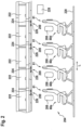
- Figure 2 shows a schematic longitudinal cross-sectional view of a section of the passenger cabin 204 of the aircraft 102 shown in Figure 1 .
- the passenger seats 81 are mounted to a floor 220 of the passenger cabin 204.
- Each of the depicted passenger seats 81 belongs to a different seat row 80a-80d.
- the seat rows 80a-80d are spaced apart from each other along the longitudinal direction L of the passenger cabin 204.
- a window 208 is provided, which allows the passengers to view the outside of the aircraft 102.
- a plurality of overhead baggage compartments 222 which provide storage space for the passengers' baggage, are provided above the passenger seats 81.
- Each seat row 80a-80d may include a plurality of passenger seats 81, for example three passenger seats 81, which are arranged next to each other along a lateral direction, which is orthogonal to the longitudinal direction L.
- the additional passenger seats, i.e. the middle seat and the window seat, of each seat row 80a-80d are not visible in Figure 2 , as they are arranged behind and therefore hidden by the depicted aisle seats 81.
- An aircraft overhead passenger service unit (PSU) 209 is provided above each of the seat rows 80a-80d, respectively.
- Each of the aircraft overhead passenger service units 209 may comprise at least one interior aircraft light.
- Each of the aircraft overhead passenger service units 209 may, for example, comprise a plurality of reading lights 224, wherein the light output of each of the reading lights 224 is directed towards one of the passenger seats 81 arranged below the respective aircraft overhead passenger service unit 209.
- Each of the aircraft overhead passenger service units 209 may further comprise one or more signal lights 226, which may, for example, light up in case a request for the cabin service personnel has been triggered by a passenger.
- the passenger cabin 204 may further comprise at least one general cabin illumination light 228 for illumination the passenger cabin 204.
- Washroom illumination lights may be installed within washrooms provided within the passenger cabin 204.
- Each of these interior aircraft lights may be an aircraft light according to an exemplary embodiment of the invention.
- Figure 3 depicts a schematic cross-sectional view of an aircraft light 2 according to an exemplary embodiment of the invention.
- the aircraft light 2 may be one of the white light emitting exterior aircraft lights, depicted in Figures 1A and 1B , or one of the interior aircraft lights depicted in Figure 2 .
- the aircraft light 2 comprises a support board 3, supporting a light source 4.
- the support board 3 may be a circuit board, in particular a printed circuit board.
- the circuit board may comprise electric connections 5, which are electrically coupled to the light source 4 for supplying electric power from an external electric power supply, which is not shown in Figure 3 , to the light source 4.
- the light source 4 comprises a light emitting semiconductor 6 for emitting light 16 having an initial light spectrum.
- the initial light spectrum may comprise light having only a single wavelength or light having a plurality of wavelengths.
- the initial light spectrum of the light 16, as emitted by the light emitting semiconductor 6, may be blue or blueish, i.e. the wavelengths of the light 16, emitted by the light emitting semiconductor 6, may predominantly be in the range of between 450 nm and 500 nm.
- Blue light is well suited for being converted into light of other colors by appropriate light converting materials and, thus, for yielding white light by mixing the original blue light with said light of other colors.
- the light emitting semiconductor 6 may, for example, include at least one of Indium Gallium Nitride (InGaN), Zinc Selenid (ZnSe), and Silicone Carbide (SiC). These materials have been found as being very effective for emitting blue light.
- InGaN Indium Gallium Nitride
- ZnSe Zinc Selenid
- SiC Silicone Carbide
- the light source 4 further comprises a first light converting material 8, which is arranged over the light emitting semiconductor 6.
- the first light converting material 8 is configured such that a first portion of the light 16, which is emitted by the light emitting semiconductor 6, is shifted towards longer wavelengths by / in the first light converting material 8. In other words, a first portion of the light 16, which is emitted by the light emitting semiconductor 6, experiences a wavelength shift, when passing through the first light converting material 8.
- the light source 4 also comprises a light transmissive layer 10, covering the first light converting material 8.
- the light transmissive layer 10 may in particular be a transparent layer, through which both the un-shifted light and the wavelength-shifted light pass in a substantially unaltered manner.
- the light source 4 comprises a support structure 9, which is arranged on the support board 3 and which supports the light emitting semiconductor 6 on a side facing away from the support board 3.
- the cavity 7 is formed in the support structure 9 around the light emitting semiconductor 6.
- the cavity 7 may have the shape of a truncated cone, having a smaller diameter at its lower end facing towards the support board 3 and having a larger diameter at its upper end facing away from the support board 3.
- the cavity 7 is filled with the first light converting material 8, such that the first light converting material 8 encloses the light emitting semiconductor 6, except for the side of the light emitting semiconductor 6 that is mounted to the support board 3.
- some or all of the components of the aircraft light 2 may have rotational symmetry around a central axis A. In other embodiments, which are not explicitly shown, some or all of the components of the aircraft light 2 may have a different shape.
- the light source 4 and/or the light emitting semiconductor 6 may, for example, have a polygonal shape, such as a rectangular shape, in particular a quadratic shape.
- the light source 4 may have a lateral extension D in the range of between 0.5 mm and 2.5 mm, in particular a lateral extension D in the range of between 1 mm and 2 mm.
- the lateral extension D may be the diameter of a light source with circular circumference or may be the length of one of the sides of a light source with quadratic circumference.
- the light source 4 further comprises a light transmissive layer 10, which covers the side of the first light converting material 8 that is opposite to the support board 3.
- a light transmissive layer 10 which covers the side of the first light converting material 8 that is opposite to the support board 3.
- an outer peripheral portion 10a of the light transmissive layer 10 additionally covers an outer peripheral portion 9a of the support structure 9.
- the aircraft light 2 further comprises a second light converting material 12 and a lens element 14.
- the second light converting material 12 is arranged over the light transmissive layer 10 of the light source 4, in particular on the side of the light transmissive layer 10 that is opposite to the first light converting material 8.
- the second light converting material 12 is configured such that the spectrum of a second portion of the light 16, which is emitted by the light emitting semiconductor 6, is shifted towards longer wavelengths by / in the second light converting material 12. In other words, some of the light 16, which is emitted by the light emitting semiconductor 6, experiences a wavelength shift when passing through the second light converting material 12.
- the second light converting material 12 As a result, a mix of light that is un-shifted in wavelength and light that is shifted in wavelength, leaves the second light converting material 12. As compared to the mix of light leaving the first light converting material 8, more light is wavelength-shifted in the mix of light leaving the second light converting material 12. In a case where the light emitting semiconductor 6 emits blue / blueish light and where the first and second wavelength converting materials 8, 12 provide a wavelength shift towards yellow light, the resulting color of the light, leaving the second light converting material 12, is a warmer / more yellowish light than the colder / more blueish light, leaving the first light converting material 8.
- the light leaving the first light converting material 8 may be a bluish kind of white
- the light leaving the second light converting material 12 may be a white shade in the aviation white color range.
- a white light output that is in accordance with the FAR may thus be achieved.
- the lens element 14 is arranged over the second light converting material 12, such that light exiting the lens element 14 forms at least a portion of the white light output of the aircraft light 2.
- the second light converting material 12 which is arranged over the light transmissive layer 10 of the light source 4, causes an additional shift of the spectrum of the light 16, which is emitted by the light emitting semiconductor 6, towards longer wavelengths.
- the second light converting material 12 may provide for a shift of the blueish white light, which exits the light transmissive layer 10 of the light source 4 and which enters the second light converting material 12, to an aviation white shade of light.
- the light output may in particular fulfill the requirements of aviation white light, as it is defined in section 25.1397 of the FAR.
- Each of the first and second light converting materials 8, 12 may be configured for emitting light having a second spectrum, when it is excited by light 16 having a first / initial spectrum, which is emitted by the light emitting semiconductor 6.
- the second spectrum may be shifted towards longer wavelengths with respect to the first spectrum, in order to achieve the desired effect of shifting the light 16 towards longer wavelengths when it passes through the respective light converting material 8, 12.
- the overall portion of wavelength-shifted light may be tuned and a desired light output may be achieved, with the desired light output resulting from a mix of light that is un-shifted in wavelength and light that is wavelength-shifted.
- the light emitting semiconductor 6, the first light converting material 8, and the light transmissive layer 10 may be provided as an integrated light source structure, in particular as a light emitting diode, which may be produced and sold as an integrated entity. Said integrated entity is at least partially covered with the second light converting material 12 for achieving above-described color conditioning.
- the light emitting diode may, in particular, be an off the shelf product, which may be produced in large numbers at low costs.
- the second light converting material 12 may be provided as a light converting layer, which is arranged on the light transmissive layer 10 of the light source 4.
- the second light converting material 12 may, for example, be a coating, which is applied to the light transmissive layer 10.
- the layer formed by the second light converting material 12 may have a thickness d of less than 1 mm, in particular a thickness d of less than 0.5 mm.
- the layer formed by the second light converting material 12 may have a thickness d of at least 0.1 mm.
- the first light converting material 8 and the second light converting material 12 may comprise the same optically active substance. In an alternative configuration, the first light converting material 8 and the second light converting material 12 may comprise different optically active substances.
- each of the first light converting material 8 and the second light converting material 12 may comprise Cerium doped Yttrium Aluminium Garnet and/or a nitridosilicate based light converting material as an optically active substance. It is also possible that one of the first light converting material 8 and the second light converting material 12 comprises Cerium doped Yttrium Aluminium Garnet and/or a nitridosilicate based light converting material as an optically active substance, while the other one of the first light converting material 8 and the second light converting material 12 comprises another optically active substance.
- the second light converting material 12 may comprise a carrier material, into which the optically active substance is embedded.
- the carrier material, including the optically active substance, may then be applied to the light transmissive layer 10 for forming the layer of the second light converting material 12 on the light transmissive layer 10.
- the carrier material may in particular include at least one of a silicone matrix, an epoxy matrix, and a polyurethane matrix.
- the light transmissive layer 10 may be a transparent layer.
- the light transmissive layer 10 may in particular be made from glass, sapphire, or silicone.
- the sapphire may be an artificial sapphire glass.
- the lens element 14 may have a predefined shape for forming a desired light output of the aircraft light 2.
- the lens element 14 can be a free-form lens that transforms the light, exiting the second light converting material 12, into a desired navigation light output, landing light output, take-off light output / etc.
- multiple light sources 4 are provided, each having a second light converting material 12 applied thereto, and that a joint lens element forms the desired light output of the aircraft light. This approach may in particular be employed in applications where a very high light intensity is required, such as for landing lights.
- the lens element 14 is shown to have a spherical outer contour for ease of illustration. It is understood that the lens element 14 may have any suitable shape for forming a desired light output.
- the lens element 14 may in particular be a silicone based lens element 14.
- the lens element 14 may be overmolded over the light source and the second light converting material 12.
- the lens element 14 may be configured to seal the light source 4 and the second light converting material 12 for protecting the light source 4 and the second light converting material 12 from adverse external influences, such as dirt, water and/ or moisture.
- the lens element 14 may further protect the light source 4 and the second light converting material 12 from mechanical impacts.
- the lens element 14 may be provided as a hard lens element 14, having a low elasticity.
- the lens element 14 may be provided as a soft lens element 14, which is elastic and which therefore allows for absorbing the forces of mechanical impact by elastic deformation.
- the aircraft light 2 may have further components not shown in Figure 3 .
- the aircraft light 2 may have a housing and a light transmissive protective cover.
- the components shown in Figure 3 may be arranged in the space between the housing and the light transmissive protective cover.
Landscapes
- Engineering & Computer Science (AREA)
- Aviation & Aerospace Engineering (AREA)
- General Engineering & Computer Science (AREA)
- Physics & Mathematics (AREA)
- Spectroscopy & Molecular Physics (AREA)
- Non-Portable Lighting Devices Or Systems Thereof (AREA)
Abstract
Description
- The present invention relates to aircraft lighting. In particular, the present invention relates to an aircraft light, further in particular to an aircraft light providing a white light output. The present invention further relates to an aircraft comprising such an aircraft light, and to a method of manufacturing an aircraft light providing a white light output.
- Almost all aircraft are equipped with numerous lights, including exterior aircraft lights and interior aircraft lights. In particular, large passenger air planes are provided with a wide variety of exterior and interior aircraft lights.
- Exterior aircraft lights are employed for a wide variety of different purposes, such as for allowing the passengers and/or air crew to view the outside, for passive visibility, for signaling purposes, etc. Examples of such exterior light units are navigation lights, also referred to as position lights, red-flashing beacon lights, white strobe anti-collision lights, wing scan lights, take-off lights, landing lights, taxi lights, runway turn-off lights, etc.
- Passenger aircraft, such as commercial air planes, comprising a passenger cabin with passenger seats, are usually equipped with general passenger cabin lights for illuminating the passenger cabin and washroom lights for illuminating washrooms. Such passenger aircraft are usually further equipped with a plurality of individually switchable passenger reading lights and a plurality of individually switchable signal lights. All of these lights are examples of interior aircraft lights.
- Many of these aircraft lights are desired to emit white light. Many exterior aircraft lights are in particular required to emit white light having a predefined chromaticity, as it is for example defined in section 25.1397 of the Federal Aviation Regulations (FAR), prescribed by the US Federal Aviation Administration (FAA). White light that fulfills such requirements is denoted as "aviation white light".
- From an efficiency and reliability point of view, it is often desirable to use light emitting semiconductor diodes (LEDs) as light sources for aircraft lights. Commercially available LEDs, however, do often not provide the desired spectrum of white light, such as aviation white light. This is in particular the case when the light emission surfaces of the LEDs are overmolded with an optically dense material, such as silicone.
- It would therefore be beneficial to provide an aircraft light that includes a semiconductor light source and that is capable to emit light having a desired kind of white light output. In particular, it would be beneficial to provide such an aircraft light that is capable to emit aviation white light, as it is defined in section 25.1397 of the FAR. It would further be beneficial to provide an aircraft having such aircraft light and a method of manufacturing such an aircraft light.
- Exemplary embodiments of the invention include an aircraft light, providing a white light output, which has a light source, wherein the light source comprises: a light emitting semiconductor for emitting light having an initial light spectrum; a first light converting material, which is arranged over the light emitting semiconductor, and a light transmissive layer, which covers the first light converting material. The first light converting material is configured such that a first portion of the light, which is emitted by the light emitting semiconductor, is shifted towards longer wavelengths by the first light converting material. The aircraft light further comprises a second light converting material, which is arranged over the light transmissive layer of the light source, in particular on the side of the light transmissive layer that is opposite to the first light converting material; and a lens element, which is arranged over the second light converting material, so that light exiting the lens element forms at least a portion of the white light output of the aircraft light. The second light converting material is configured such that a second portion of the light, which is emitted by the light emitting semiconductor, is shifted towards longer wavelengths by the second light converting material.
- The initial light spectrum may comprise light having only a single wavelength, or light having a plurality of wavelengths.
- Exemplary embodiments of the invention also include a method of manufacturing an aircraft light, which provides a white light output in operation, wherein the method comprises:
- providing a light source that comprises a light emitting semiconductor for emitting light having an initial light spectrum, a first light converting material, arranged over the light emitting semiconductor, and a light transmissive layer, covering the first light converting material, wherein the first light converting material is configured to effect a wavelength shift towards longer wavelengths for a first portion of the light, emitted by the light emitting semiconductor;
- arranging a second light converting material over the light transmissive layer of the light source, wherein the second light converting material is configured to effect a wavelength shift towards longer wavelengths for a second portion of the light, emitted by the light emitting semiconductor; and
- arranging a lens element over the second light converting material.
- In an aircraft light according to an exemplary embodiment of the invention, the spectrum of a portion of the light, which is emitted by the light emitting semiconductor, is shifted towards longer wavelengths, i.e. towards the red side of the spectrum, by the first light converting material, which is provided as part of the light source. This effect may, however, not be sufficient for generating the desired white light output of the aircraft light, i.e. a white light output having the desired chromaticity. The chromaticity may, for example, be represented in an International Commission on Illumination (CIE) 1931 chromaticity diagram. The spectrum shifting effect caused by the first light converting material may in particular not be sufficient in cases where a light output surface of the light source is covered with an optically dense material, such as silicone, because the optically dense material reduces the occurrence of internal reflection at said light output surface and, therefore, reduces the instances of wavelength shifting within the first light converting material.
- The second light converting material, when arranged over the light transmissive layer of the light source, causes additional instances of wavelength shifting and, therefore, causes a further shift of the spectrum of a portion of the light, which is emitted by the light emitting semiconductor. The second light converting material may in particular cause an additional shift of the spectrum of a portion of light that is emitted by the light emitting semiconductor and that has not been shifted by the first light converting material.
- The above described effect of the second light converting material results in an additional shift of the spectrum of the light emitted by the aircraft light towards longer wavelengths. By appropriately choosing the characteristics and the thickness of the second light converting material, the combination of the first and second light converting materials may cause a shift of the spectrum of the emitted light that results in the aircraft light emitting a desired shade of white light. In particular, the aircraft light may thus emit a white light output having a spectrum that is within or sufficiently close to aviation white light, as it is defined in section 25.1397 of the FAR.
- In case the aircraft light is an interior aircraft light, such as a passenger reading light, the spectrum of the light output may be shifted even further, i.e. beyond the spectrum of aviation white light, in order to output "warm" white light. Such "warm" white light may be perceived as more pleasant by the human eye.
- Each of the first and second light converting materials may be configured for emitting light having a second spectrum, when it is excited by light having a first spectrum, which is emitted by the light emitting semiconductor. The second spectrum may be shifted towards longer wavelengths with respect to the first spectrum. Absorbing blue light and emitting yellow or red light, i.e. light having longer wavelengths than the absorbed blue light, achieves the desired effect of shifting the light towards longer wavelengths, when it passes through the respective light converting material. Due to the color mixing of blue light, passing through the respective light converting material in an unaltered manner, and yellow / red light, having experienced the wavelength shift in the respective light converting material, the desired white light output may result.
- In an embodiment, the first light converting material and/or the second light converting material may comprise Cerium doped Yttrium Aluminium Garnet and/or a nitridosilicate based light converting material. Such materials have been found to be very effective in causing the desired shift of the spectrum of incoming light towards longer wavelengths.
- In the field of wavelength converted light sources, light converting materials are often referred to as phosphors. Accordingly, it can be said that the light source of the aircraft light, as described herein, comprises a first phosphor and that a second phosphor is arranged over the light transmissive layer of the light source. The terms light converting material and phosphor / phosphor material may be used interchangeably in the context of the present description.
- In an embodiment, the first light converting material and the second light converting material may have the same wavelength shifting characteristics. In particular, the first light converting material and the second light converting material may comprise the same optically active substance, such as Cerium doped Yttrium Aluminium Garnet and/or a nitridosilicate based light converting material.
- In an embodiment, the second light converting material comprises an optically active substance, such as Cerium doped Yttrium Aluminium Garnet and/or a nitridosilicate based light converting material, that is embedded into a carrier material. The may allow for conveniently, efficiently, and reliably applying and fixing the optically active substance to the light transmissive layer of the light source.
- In an embodiment, the carrier material includes a silicone matrix or an epoxy matrix or a polyurethane matrix. Such matrix materials have been found as well-suited for applying and permanently fixing the optically active substance to the light transmissive layer of the light source.
- In an embodiment, the initial light spectrum, i.e. the spectrum of the light, which is emitted by the light emitting semiconductor, may be blue or blueish, i.e. the wavelengths of the light, emitted by the light emitting semiconductor, may predominantly be in a range of between 450 nm and 500 nm. Blue light is well suited for being converted other light color(s) by appropriate light converting materials, with the remaining blue light and the other light color(s) then jointly providing white light.
- In an embodiment, the light emitting semiconductor includes at least one of Indium Gallium Nitride (InGaN), Zinc Selenid (ZnSe), and Silicone Carbide (SiC). These materials have been found as well suited for manufacturing light emitting semiconductors that emit blue / blueish light.
- In an embodiment, the white light output may be aviation white light, i.e. white light which fulfills the requirements as defined in section 25.1397 of the FAR.
- In an embodiment, the second light converting material is provided as a light converting layer, which is arranged on the light transmissive layer of the light source, in particular on the side of the light transmissive layer facing away from the first light converting material. In this way, the light transmissive layer may be sandwiched between the first and second light converting materials. The light transmissive layer may in particular be coated with the second light converting material.
- In an embodiment, the second light converting material has a thickness of less than 1 mm, the second light converting material may in particular have a thickness of less than 0.5 mm. The second light converting material may have a thickness of at least 0.1 mm. A thickness of less than 1 mm, in particular a thickness of less than 0.5 mm, has been found as resulting in a suitable shift of the spectrum of the light, emitted by the light source, towards longer wavelengths, without unduly reducing the intensity of the light emitted by the light source.
- In an embodiment, the light transmissive layer is a transparent layer, the light transmissive layer may in particular be a transparent layer that is made from glass or sapphire. The term sapphire is commonly used in the field of semiconductor light sources for the upper light transmissive layer. The term sapphire may refer to artificial sapphire glass. The light transmissive layer may be made from any suitable material, such as from the mentioned glass or sapphire, such as from silicone, or from other suitable materials that are able to sustain the operating temperature of the semiconductor light source.
- In an embodiment, the lens element is a silicone based lens element. A silicone based lens element has been found as being well-suited for reliably protecting the light source and the second light converting material from adverse external influences, such as dirt, water, moisture and mechanical impacts. Also, silicone has been found to have good optical properties for forming the lens element.
- In an embodiment, the lens element may be overmolded over the light source and the second light converting material for covering the light source and the second light converting material. In a method according to an exemplary embodiment of the invention, arranging the lens element over the second light converting material may include overmolding the lens element over the light source and the second light converting material.
- The lens element may be provided as a hard lens element, having a low elasticity, or as a soft lens element, which has some elasticity for absorbing the forces of mechanical impact by elastic deformation.
- In an embodiment, the light emitting semiconductor, the first light converting material, and the light transmissive layer are provided as an integrated light source structure, in particular as an integrated light emitting diode (LED). The LED may, in particular, be an off the shelf product, which may be produced in large numbers at lows costs. Such an off the shelf LED may be modified, in order to emit light having a desired spectrum of white light, by applying the second light converting material to the light transmissive layer of the LED.
- In an embodiment, the aircraft light comprises a plurality of light sources, wherein each of the plurality of light sources has a light emitting semiconductor, a first light converting material, and a light transmissive layer, respectively. Each of the plurality of light sources may have any of the features, alone or in combination, as has been described before. By providing a plurality of light sources, a high intensity of the white light output, emitted by the aircraft light, may be achieved.
- In an embodiment comprising a plurality of light sources, each of the plurality of light sources may be provided with a respective second light converting material and a respective lens element.
- In an alternative embodiment, a common lens element may be arranged over a plurality of light sources, wherein each light source is provided with a respective second light converting material. The common lens element may, for example, be configured for forming a highly targeted light output of the aircraft light. In particular, the highly targeted light output may be used for employing the aircraft light as an aircraft headlight, such as a landing light or a take-off light.
- In an embodiment, the aircraft light is an exterior aircraft light, i.e. an aircraft light which is configured for emitting light from an aircraft into an outside environment of the aircraft. The exterior aircraft light may in particular be one of a take-off light, a landing light, a taxi light, a runway turn-off light, a navigation light, in particular a white navigation light, and a white strobe anti-collision light. The exterior aircraft light may also be a multi-functional light, which combines the functionalities of at least two of a take-off light, a landing light, a taxi light, a runway turn-off light, a navigation light, in particular a white navigation light, and a white strobe anti-collision light.
- In an embodiment, the aircraft light is an interior aircraft light, which is provided within an aircraft for illuminating an area or space within the aircraft. The interior aircraft light may in particular be a general cabin illumination light for illuminating at least a potion of the cabin of an aircraft, a personal passenger reading light, a washroom illumination light for illuminating a washroom of an aircraft, or a signal light. The signal light may, for example, be a non-smoking light, a fasten-your-seatbelt light or an indicator light which lights up in case a request for the cabin service personnel has been triggered. An interior aircraft light according to an exemplary embodiment of the invention may also be used for indicating an exit, an emergency exit and/or the shortest way to the nearest exit and/or emergency exit.
- Exemplary embodiments of the invention further include an aircraft, in particular an airplane or a helicopter, comprising at least one aircraft light according to an exemplary embodiment of the invention.
- Further exemplary embodiments of the invention are described below with respect to the accompanying drawings, wherein:
-
Figure 1A shows a schematic top view of an aircraft, which is equipped with a variety of exterior aircraft lights. -
Figure 1B shows a schematic front view of the aircraft shown inFigure 1A . -
Figure 2 shows a schematic longitudinal cross-sectional view of a section of the passenger cabin of the aircraft shown inFigures 1A and1B . -
Figure 3 depicts a schematic cross-sectional view of an aircraft light according to an exemplary embodiment of the invention. -
Figures 1A and1B , jointly referred to asFigure 1 herein, show anaircraft 102, in particular an airplane, comprising afuselage 130, which houses acockpit 202 and apassenger cabin 204, and twowings 140, extending from thefuselage 130. Twohorizontal stabilisers 170 and avertical stabiliser 180 extend from a rear portion of thefuselage 130. Anengine 150 is mounted to each of thewings 140, respectively. Theaircraft 102 is shown in a top view inFigure 1A and shown in a front view inFigure 1B . - The
aircraft 102 ofFigure 1 is equipped with a wide variety of exterior lights. In particular, theaircraft 102 is equipped with threenavigation lights 106, twologo lights 108, twowing scan lights 110, twoengine scan lights 112, two runway turn-offlights 114, two cargo loading lights 116, three whiteanti-collision strobe lights 118, two red-flashinganti-collision beacon lights 120, alanding light 122, a take-off light 124 and ataxi light 126. It is pointed out that these kinds of lights and their numbers are exemplary only and that theaircraft 102 may be equipped with additional lights that are not shown. - The three
navigation lights 106 are positioned in the left andright wing tips 142 as well as at the thetail 160 of theaircraft 102. In normal flight conditions, each one of thenavigation lights 106 emits light in one of the colors green, red and white, thus indicating to the aircraft environment if they are looking at the port side, starboard side or tail side of the aircraft. Thenavigation lights 106 are normally on during all phases of the flight and in all flight conditions. - The logo lights 108 are directed to the
vertical stabiliser 180 of theaircraft 102 and are provided for illuminating the same, in particular for illuminating the logo commonly provided on thevertical stabiliser 180. The logo lights 108 are normally switched on for the entire duration of the flight during night flights. It is also possible that the logo lights are only used during taxiing on the airport and are normally switched off during the flight. - The
wing scan lights 110 and theengine scan lights 112 are positioned on the left and right sides of thefuselage 130, in front of theroots 144 of thewings 140 of theaircraft 102. Thewing scan lights 110 and theengine scan lights 112 are normally off during the flight and may be switched on periodically or upon reasonable cause by the pilots or by the aircrew, in order to check thewings 140 and theengines 150 of theaircraft 102. - The runway turn-off
lights 114 are positioned in theroots 144 of thewings 140. The runway turn-offlights 114 are directed forwards and are normally switched off during the flight and switched on during taxiing, at least at night. - The
cargo loading lights 116 are positioned on the left and right sides of thefuselage 130, behind thewings 140 and in front of the tail structure of theaircraft 102. They are normally switched off during the flight of theaircraft 102. - The white
anti-collision strobe lights 118 are positioned in the left andright wing tips 142 as well as at thetail 160 of theaircraft 102. The whiteanti-collision strobe lights 118 emit respective sequences of white light flashes during normal operation of theaircraft 102. It is also possible that the whiteanti-collision strobe lights 118 are only operated during night and in bad weather conditions. - The red-flashing
anti-collision beacon lights 120 are positioned on the top and the bottom of thefuselage 130 of theaircraft 102. They are arranged at the height of the wings in the longitudinal direction of theaircraft 102. While one of the red-flashing anti-collision beacon lights 120 is disposed on the top of thefuselage 130, the other one of the red-flashing anti-collision beacon lights 120 is disposed on the bottom of thefuselage 130 and is therefore shown in phantom inFigure 1A . The red-flashinganti-collision beacon lights 120 are normally switched on during taxiing and during take-off and landing. Their output is perceived as a sequence of red light flashes in a given viewing direction. - In the embodiment depicted in
Figures 1A and1B , the runway turn-offlights 114 are located in thewings 140, in particular in theroots 144 of thewings 140, and thelanding light 122, the take-off light 124 and thetaxi light 126 are mounted to thefront gear 135 of theaircraft 102. Thefront gear 135 is stored within thefuselage 130 of theaircraft 102 during flight, and it is deployed during landing, taxiing and take off. - In alternative embodiments, which are not explicitly shown in the figures, the runway turn-off
lights 114 may be mounted to thefront gear 135 and/or at least one of thelanding light 122, the take-off light 124 and thetaxi light 126 may be installed in thewings 140, in particular in theroots 144 of thewings 140, of theaircraft 102. - The
aircraft 102 may also comprise a multi-functional light, which combines the functionalities of at least two of thelanding light 122, the take-off light 124, thetaxi light 126, the runway turn-offlights 114, anavigation light 106, and a white strobeanti-collision light 118. - Since the
landing light 122, the take-off light 124, and thetaxi light 126 are arranged on the bottom of theaircraft 102, they are also depicted in phantom inFigure 1A . - Each of these exterior aircraft lights, which has a white light output, may be an aircraft light according to an exemplary embodiment of the invention.
-
Figure 2 shows a schematic longitudinal cross-sectional view of a section of thepassenger cabin 204 of theaircraft 102 shown inFigure 1 . - Four
seats 81, which are also referred to as passenger seats 81, are visible inFigure 2 . The passenger seats 81 are mounted to afloor 220 of thepassenger cabin 204. Each of the depictedpassenger seats 81 belongs to adifferent seat row 80a-80d. Theseat rows 80a-80d are spaced apart from each other along the longitudinal direction L of thepassenger cabin 204. - For each of the
seat rows 80a-80d, awindow 208 is provided, which allows the passengers to view the outside of theaircraft 102. Further, a plurality of overhead baggage compartments 222, which provide storage space for the passengers' baggage, are provided above the passenger seats 81. - Each
seat row 80a-80d may include a plurality ofpassenger seats 81, for example threepassenger seats 81, which are arranged next to each other along a lateral direction, which is orthogonal to the longitudinal direction L. The additional passenger seats, i.e. the middle seat and the window seat, of eachseat row 80a-80d are not visible inFigure 2 , as they are arranged behind and therefore hidden by the depicted aisle seats 81. - An aircraft overhead passenger service unit (PSU) 209 is provided above each of the
seat rows 80a-80d, respectively. - Each of the aircraft overhead
passenger service units 209 may comprise at least one interior aircraft light. Each of the aircraft overheadpassenger service units 209 may, for example, comprise a plurality of readinglights 224, wherein the light output of each of the reading lights 224 is directed towards one of the passenger seats 81 arranged below the respective aircraft overheadpassenger service unit 209. Each of the aircraft overheadpassenger service units 209 may further comprise one ormore signal lights 226, which may, for example, light up in case a request for the cabin service personnel has been triggered by a passenger. - The
passenger cabin 204 may further comprise at least one generalcabin illumination light 228 for illumination thepassenger cabin 204. Washroom illumination lights may be installed within washrooms provided within thepassenger cabin 204. - Each of these interior aircraft lights may be an aircraft light according to an exemplary embodiment of the invention.
-
Figure 3 depicts a schematic cross-sectional view of an aircraft light 2 according to an exemplary embodiment of the invention. The aircraft light 2 may be one of the white light emitting exterior aircraft lights, depicted inFigures 1A and1B , or one of the interior aircraft lights depicted inFigure 2 . - The aircraft light 2 comprises a
support board 3, supporting alight source 4. Thesupport board 3 may be a circuit board, in particular a printed circuit board. The circuit board may compriseelectric connections 5, which are electrically coupled to thelight source 4 for supplying electric power from an external electric power supply, which is not shown inFigure 3 , to thelight source 4. - The
light source 4 comprises alight emitting semiconductor 6 for emitting light 16 having an initial light spectrum. The initial light spectrum may comprise light having only a single wavelength or light having a plurality of wavelengths. - The initial light spectrum of the light 16, as emitted by the
light emitting semiconductor 6, may be blue or blueish, i.e. the wavelengths of the light 16, emitted by thelight emitting semiconductor 6, may predominantly be in the range of between 450 nm and 500 nm. Blue light is well suited for being converted into light of other colors by appropriate light converting materials and, thus, for yielding white light by mixing the original blue light with said light of other colors. - The
light emitting semiconductor 6 may, for example, include at least one of Indium Gallium Nitride (InGaN), Zinc Selenid (ZnSe), and Silicone Carbide (SiC). These materials have been found as being very effective for emitting blue light. - The
light source 4 further comprises a firstlight converting material 8, which is arranged over thelight emitting semiconductor 6. The firstlight converting material 8 is configured such that a first portion of the light 16, which is emitted by thelight emitting semiconductor 6, is shifted towards longer wavelengths by / in the firstlight converting material 8. In other words, a first portion of the light 16, which is emitted by thelight emitting semiconductor 6, experiences a wavelength shift, when passing through the firstlight converting material 8. - This is illustrated in
Figure 3 as follows. Some light rays, which pass through the firstlight converting material 8 in an un-shifted manner, are depicted as solid lines. Other light rays, which experience a wavelength shift in the firstlight converting material 8 and which are thus part of above mentioned first portion of the light 16, are indicated as solid lines, when leaving thelight emitting semiconductor 6, and change from being solid lines to being dashed lines within the firstlight converting material 8, with this change in line style indicating the wavelength shift. In this way, a mix of light that is un-shifted in wavelength and light that is shifted in wavelength, leaves the firstlight converting material 8. While the lines, changing their line style from solid to dashed, are shown as straight lines for ease of illustration, it is understood that the light may also change direction at the point of wavelength conversion. - The
light source 4 also comprises alight transmissive layer 10, covering the firstlight converting material 8. Thelight transmissive layer 10 may in particular be a transparent layer, through which both the un-shifted light and the wavelength-shifted light pass in a substantially unaltered manner. - In the exemplary embodiment depicted in
Figure 3 , thelight source 4 comprises asupport structure 9, which is arranged on thesupport board 3 and which supports thelight emitting semiconductor 6 on a side facing away from thesupport board 3. - On the side facing away from the
support board 3, acavity 7 is formed in thesupport structure 9 around thelight emitting semiconductor 6. Thecavity 7 may have the shape of a truncated cone, having a smaller diameter at its lower end facing towards thesupport board 3 and having a larger diameter at its upper end facing away from thesupport board 3. - The
cavity 7 is filled with the firstlight converting material 8, such that the firstlight converting material 8 encloses thelight emitting semiconductor 6, except for the side of thelight emitting semiconductor 6 that is mounted to thesupport board 3. - In the exemplary embodiment depicted in
Figure 3 , some or all of the components of the aircraft light 2 may have rotational symmetry around a central axis A. In other embodiments, which are not explicitly shown, some or all of the components of the aircraft light 2 may have a different shape. Thelight source 4 and/or thelight emitting semiconductor 6 may, for example, have a polygonal shape, such as a rectangular shape, in particular a quadratic shape. - The
light source 4 may have a lateral extension D in the range of between 0.5 mm and 2.5 mm, in particular a lateral extension D in the range of between 1 mm and 2 mm. The lateral extension D may be the diameter of a light source with circular circumference or may be the length of one of the sides of a light source with quadratic circumference. - The
light source 4 further comprises alight transmissive layer 10, which covers the side of the firstlight converting material 8 that is opposite to thesupport board 3. In the exemplary embodiment depicted inFigure 3 , an outerperipheral portion 10a of thelight transmissive layer 10 additionally covers an outer peripheral portion 9a of thesupport structure 9. - The aircraft light 2 further comprises a second
light converting material 12 and alens element 14. - The second
light converting material 12 is arranged over thelight transmissive layer 10 of thelight source 4, in particular on the side of thelight transmissive layer 10 that is opposite to the firstlight converting material 8. The secondlight converting material 12 is configured such that the spectrum of a second portion of the light 16, which is emitted by thelight emitting semiconductor 6, is shifted towards longer wavelengths by / in the secondlight converting material 12. In other words, some of the light 16, which is emitted by thelight emitting semiconductor 6, experiences a wavelength shift when passing through the secondlight converting material 12. - This is illustrated in
Figure 3 as follows. Some light rays, which have passed through the firstlight converting material 8 in an un-shifted manner and which pass through the secondlight converting material 12 in an un-shifted manner, are depicted as solid lines through the secondlight converting material 12. Other light rays, which have passed through the firstlight converting material 8 in an un-shifted manner and which experience a wavelength shift in the secondlight converting material 12 and which are thus part of above mentioned second portion of the light 16, are indicated as solid lines, when entering the secondlight converting material 12, and change from being solid lines to being dashed lines within the secondlight converting material 12, with this change in line style indicating the wavelength shift. Yet other light rays, which have experienced a wavelength shift in the firstlight converting material 8 and which pass through the secondlight converting material 12, are indicated as dashed lines through the secondlight converting material 12. While the lines, changing their line style from solid to dashed, are shown as straight lines for ease of illustration, it is understood that the light may also change direction at the point of wavelength conversion. - As a result, a mix of light that is un-shifted in wavelength and light that is shifted in wavelength, leaves the second
light converting material 12. As compared to the mix of light leaving the firstlight converting material 8, more light is wavelength-shifted in the mix of light leaving the secondlight converting material 12. In a case where thelight emitting semiconductor 6 emits blue / blueish light and where the first and secondwavelength converting materials light converting material 12, is a warmer / more yellowish light than the colder / more blueish light, leaving the firstlight converting material 8. In particular, while the light leaving the firstlight converting material 8 may be a bluish kind of white, the light leaving the secondlight converting material 12 may be a white shade in the aviation white color range. A white light output that is in accordance with the FAR may thus be achieved. - The
lens element 14 is arranged over the secondlight converting material 12, such that light exiting thelens element 14 forms at least a portion of the white light output of the aircraft light 2. - The second
light converting material 12, which is arranged over thelight transmissive layer 10 of thelight source 4, causes an additional shift of the spectrum of the light 16, which is emitted by thelight emitting semiconductor 6, towards longer wavelengths. In particular, the secondlight converting material 12 may provide for a shift of the blueish white light, which exits thelight transmissive layer 10 of thelight source 4 and which enters the secondlight converting material 12, to an aviation white shade of light. - This results in a "warmer" light output of the aircraft light 2, as compared to the chromaticity of the light that exits the
light transmissive layer 10 of thelight source 4. The light output, as emitted by the aircraft light 2 after the shift in the secondlight converting material 12, may in particular fulfill the requirements of aviation white light, as it is defined in section 25.1397 of the FAR. - Each of the first and second
light converting materials light emitting semiconductor 6. The second spectrum may be shifted towards longer wavelengths with respect to the first spectrum, in order to achieve the desired effect of shifting the light 16 towards longer wavelengths when it passes through the respectivelight converting material light converting materials - The
light emitting semiconductor 6, the firstlight converting material 8, and thelight transmissive layer 10 may be provided as an integrated light source structure, in particular as a light emitting diode, which may be produced and sold as an integrated entity. Said integrated entity is at least partially covered with the secondlight converting material 12 for achieving above-described color conditioning. - The light emitting diode may, in particular, be an off the shelf product, which may be produced in large numbers at low costs.
- As depicted in
Figure 3 , the secondlight converting material 12 may be provided as a light converting layer, which is arranged on thelight transmissive layer 10 of thelight source 4. The secondlight converting material 12 may, for example, be a coating, which is applied to thelight transmissive layer 10. - The layer formed by the second
light converting material 12 may have a thickness d of less than 1 mm, in particular a thickness d of less than 0.5 mm. The layer formed by the secondlight converting material 12 may have a thickness d of at least 0.1 mm. - The first
light converting material 8 and the secondlight converting material 12 may comprise the same optically active substance. In an alternative configuration, the firstlight converting material 8 and the secondlight converting material 12 may comprise different optically active substances. - In an exemplary embodiment, each of the first
light converting material 8 and the secondlight converting material 12 may comprise Cerium doped Yttrium Aluminium Garnet and/or a nitridosilicate based light converting material as an optically active substance. It is also possible that one of the firstlight converting material 8 and the secondlight converting material 12 comprises Cerium doped Yttrium Aluminium Garnet and/or a nitridosilicate based light converting material as an optically active substance, while the other one of the firstlight converting material 8 and the secondlight converting material 12 comprises another optically active substance. - The second
light converting material 12 may comprise a carrier material, into which the optically active substance is embedded. The carrier material, including the optically active substance, may then be applied to thelight transmissive layer 10 for forming the layer of the secondlight converting material 12 on thelight transmissive layer 10. - The carrier material may in particular include at least one of a silicone matrix, an epoxy matrix, and a polyurethane matrix.
- The
light transmissive layer 10 may be a transparent layer. Thelight transmissive layer 10 may in particular be made from glass, sapphire, or silicone. The sapphire may be an artificial sapphire glass. - The
lens element 14 may have a predefined shape for forming a desired light output of the aircraft light 2. For example, thelens element 14 can be a free-form lens that transforms the light, exiting the secondlight converting material 12, into a desired navigation light output, landing light output, take-off light output / etc. It is also possible that multiplelight sources 4 are provided, each having a secondlight converting material 12 applied thereto, and that a joint lens element forms the desired light output of the aircraft light. This approach may in particular be employed in applications where a very high light intensity is required, such as for landing lights. In the illustrative embodiment ofFigure 3 , thelens element 14 is shown to have a spherical outer contour for ease of illustration. It is understood that thelens element 14 may have any suitable shape for forming a desired light output. - The
lens element 14 may in particular be a silicone basedlens element 14. - The
lens element 14 may be overmolded over the light source and the secondlight converting material 12. - The
lens element 14 may be configured to seal thelight source 4 and the secondlight converting material 12 for protecting thelight source 4 and the secondlight converting material 12 from adverse external influences, such as dirt, water and/ or moisture. Thelens element 14 may further protect thelight source 4 and the secondlight converting material 12 from mechanical impacts. - The
lens element 14 may be provided as ahard lens element 14, having a low elasticity. Alternatively, thelens element 14 may be provided as asoft lens element 14, which is elastic and which therefore allows for absorbing the forces of mechanical impact by elastic deformation. - The aircraft light 2 may have further components not shown in
Figure 3 . For example, the aircraft light 2 may have a housing and a light transmissive protective cover. In that case, the components shown inFigure 3 may be arranged in the space between the housing and the light transmissive protective cover. - While the invention has been described with reference to exemplary embodiments, it will be understood by those skilled in the art that various changes may be made and equivalents may be substituted for elements thereof without departing from the scope of the invention. In addition, many modifications may be made to adapt a particular situation or material to the teachings of the invention without departing from the essential scope thereof. Therefore, it is intended that the invention not be limited to the particular embodiment disclosed, but that the invention will include all embodiments falling within the scope of the appended claims.
Claims (15)
- Aircraft light (2) with a white light output, the aircraft light (2) comprising:a light source (4) that comprises:a light emitting semiconductor (6) for emitting light (16) having an initial light spectrum;a first light converting material (8), arranged over the light emitting semiconductor (6), wherein a first portion of the light (16), emitted by the light emitting semiconductor (6), is shifted towards longer wavelengths by the first light converting material (8); anda light transmissive layer (10), covering the first light converting material (8);wherein the aircraft light (2) further comprises:a second light converting material (12), arranged over the light transmissive layer (10) of the light source (4), wherein a second portion of the light (16), emitted by the light emitting semiconductor (6), is shifted towards longer wavelengths by the second light converting material (12); anda lens element (14), arranged over the second light converting material (12), with light exiting the lens element (14) forming at least a portion of the white light output of the aircraft light (2).
- Aircraft light (2) according to claim 1,wherein the initial light spectrum is blueish;
and/orwherein the white light output is aviation white. - Aircraft light (2) according to claim 1 or 2,wherein the second light converting material (12) is provided as a light converting layer, arranged on the light transmissive layer (10) of the light source (4);
and/orwherein the second light converting material (12) has a thickness (d) of less than 1 mm, in particular a thickness of less than 0.5 mm. - Aircraft light (2) according to any of the preceding claims,wherein the first light converting material (8) and/or the second light converting material (12) comprise(s) Cerium doped Yttrium Aluminium Garnet and/or a nitridosilicate based light converting material;
and/orwherein the first light converting material (8) and the second light converting material (12) comprise the same optically active substance. - Aircraft light (2) according to any of the preceding claims, wherein the light transmissive layer (10) is a transparent layer, in particular a transparent layer made from glass or sapphire.
- Aircraft light (2) according to any of the preceding claims, wherein the second light converting material (12) comprises an optically active substance embedded into a carrier material, in particular embedded into a silicone matrix or an epoxy matrix or a polyurethane matrix.
- Aircraft light (2) according to any of the preceding claims,wherein the lens element (14) is a silicone based lens element (14);
and/orwherein the lens element (14) is overmolded over the light source (4) and the second light converting material (12). - Aircraft light (2) according to any of the preceding claims, wherein the light emitting semiconductor (6), the first light converting material (8), and the light transmissive layer (10) are provided as an integrated light source structure, wherein the light emitting semiconductor (6), the first light converting material (8), and the light transmissive layer (10) are in particular provided as a light emitting diode.
- Aircraft light (2) according to any of the preceding claims, wherein the aircraft light (2) comprises a plurality of light sources (4), wherein each of the plurality of light sources (4) has a light emitting semiconductor (6), a first light converting material (8), and a light transmissive layer (10), and wherein each of the plurality of light sources (4) is provided with a respective second light converting material (12) and a respective lens element (14).
- Aircraft light (2) according to any of the preceding claims, wherein the aircraft light (2) is an exterior aircraft light (2), wherein the exterior aircraft light (2) is in particular a landing light (122), a take-off light (124), a taxi light (126), a runway turn-off light (114), a navigation light (106), a white strobe anti-collision light (118), or a multi-functional light, which combines the functionalities of at least two of a landing light (122), a take-off light (124), a taxi light (126), a runway turn-off light (114), a navigation light (106) and a white strobe anti-collision light (118).
- Aircraft light (2) according to any of claims 1 to 9, wherein the aircraft light (2) is an interior aircraft light (2), wherein the interior aircraft light (2) is in particular a passenger reading light (224), a signal light (226), a general cabin illumination light (228), or a washroom illumination light.
- Aircraft (102), in particular an airplane or a helicopter, comprising at least one aircraft light (2) according to any of the preceding claims.
- Method of manufacturing an aircraft light (2) with a white light output, wherein the method comprises:providing a light source (4) that comprises a light emitting semiconductor (6) for emitting light (16) having an initial light spectrum, a first light converting material (8), arranged over the light emitting semiconductor (6), and a light transmissive layer (10), covering the first light converting material (8), wherein the first light converting material (8) is configured to effect a wavelength shift towards longer wavelengths for a first portion of the light (16), emitted by the light emitting semiconductor (6);arranging a second light converting material (12) over the light transmissive layer (10) of the light source (4), wherein the second light converting material (12) is configured to effect a wavelength shift towards longer wavelengths for a second portion of the light (16), emitted by the light emitting semiconductor (6); andarranging a lens element (14) over the second light converting material (12).
- Method according to claim 13, wherein the light emitting semiconductor (6), the first light converting material (8), and the light transmissive layer (10) are provided as an integrated light source structure, wherein the light emitting semiconductor (6), the first light converting material (8), and the light transmissive layer (10) are in particular provided as a light emitting diode.
- Method according to claim 13 or 14, wherein said arranging of the lens element (14) over the second light converting material (12) includes overmolding the lens element (14) over the light source (4) and the second light converting material (12).
Priority Applications (2)
| Application Number | Priority Date | Filing Date | Title |
|---|---|---|---|
| EP23153170.8A EP4406858B1 (en) | 2023-01-24 | 2023-01-24 | Aircraft light, aircraft comprising an aircraft light, and method of manufacturing an aircraft light |
| US18/408,387 US12072093B2 (en) | 2023-01-24 | 2024-01-09 | Aircraft light, aircraft comprising an aircraft light, and method of manufacturing an aircraft light |
Applications Claiming Priority (1)
| Application Number | Priority Date | Filing Date | Title |
|---|---|---|---|
| EP23153170.8A EP4406858B1 (en) | 2023-01-24 | 2023-01-24 | Aircraft light, aircraft comprising an aircraft light, and method of manufacturing an aircraft light |
Publications (2)
| Publication Number | Publication Date |
|---|---|
| EP4406858A1 true EP4406858A1 (en) | 2024-07-31 |
| EP4406858B1 EP4406858B1 (en) | 2026-04-15 |
Family
ID=85150587
Family Applications (1)
| Application Number | Title | Priority Date | Filing Date |
|---|---|---|---|
| EP23153170.8A Active EP4406858B1 (en) | 2023-01-24 | 2023-01-24 | Aircraft light, aircraft comprising an aircraft light, and method of manufacturing an aircraft light |
Country Status (2)
| Country | Link |
|---|---|
| US (1) | US12072093B2 (en) |
| EP (1) | EP4406858B1 (en) |
Citations (7)
| Publication number | Priority date | Publication date | Assignee | Title |
|---|---|---|---|---|
| US20020079505A1 (en) * | 2000-12-21 | 2002-06-27 | Stefan Becker | Semiconductor light unit and method for production of the same |
| US20070246734A1 (en) * | 2006-04-10 | 2007-10-25 | Samsung Electro-Mechanics Co., Ltd. | Multilayered white light emitting diode using quantum dots and method of fabricating the same |
| US20090010013A1 (en) * | 2007-07-02 | 2009-01-08 | Andre Hessling | Light for a vehicle, particularly flash warning light for an aircraft |
| WO2015178981A1 (en) * | 2014-05-20 | 2015-11-26 | The Boeing Company | Lighting and data communication system using a remotely located lighting array |
| US20190194537A1 (en) * | 2016-09-05 | 2019-06-27 | Toray Industries, Inc. | Color conversion composition, color conversion sheet, and light-emitting body, lighting device, backlight unit, and display each including same |
| US11060682B1 (en) * | 2020-01-23 | 2021-07-13 | Honeywell International Inc | Architecture and method for aircraft lighting system using a centralized blue light source and a plurality of distributed passive light-heads |
| WO2022265068A1 (en) * | 2021-06-17 | 2022-12-22 | 大日本印刷株式会社 | Optical member, planar light source device, and display device |
Family Cites Families (6)
| Publication number | Priority date | Publication date | Assignee | Title |
|---|---|---|---|---|
| EP2282354B1 (en) | 1996-06-26 | 2013-09-11 | OSRAM Opto Semiconductors GmbH | Light-emitting semiconductor device with luminescence conversion element |
| JP2010532104A (en) | 2007-06-27 | 2010-09-30 | ザ リージェンツ オブ ザ ユニバーシティ オブ カリフォルニア | Optical design for high efficiency white light emitting diodes |
| JPWO2009107535A1 (en) | 2008-02-25 | 2011-06-30 | 株式会社東芝 | White LED lamp, backlight, light emitting device, display device, and illumination device |
| US20110031516A1 (en) | 2009-08-07 | 2011-02-10 | Koninklijke Philips Electronics N.V. | Led with silicone layer and laminated remote phosphor layer |
| US9388959B2 (en) | 2012-03-02 | 2016-07-12 | Osram Sylvania Inc. | White-light emitter having a molded phosphor sheet and method of making same |
| EP3205584B1 (en) | 2016-02-12 | 2020-06-03 | Goodrich Lighting Systems GmbH | Exterior aircraft light and aircraft comprising the same |
-
2023
- 2023-01-24 EP EP23153170.8A patent/EP4406858B1/en active Active
-
2024
- 2024-01-09 US US18/408,387 patent/US12072093B2/en active Active
Patent Citations (7)
| Publication number | Priority date | Publication date | Assignee | Title |
|---|---|---|---|---|
| US20020079505A1 (en) * | 2000-12-21 | 2002-06-27 | Stefan Becker | Semiconductor light unit and method for production of the same |
| US20070246734A1 (en) * | 2006-04-10 | 2007-10-25 | Samsung Electro-Mechanics Co., Ltd. | Multilayered white light emitting diode using quantum dots and method of fabricating the same |
| US20090010013A1 (en) * | 2007-07-02 | 2009-01-08 | Andre Hessling | Light for a vehicle, particularly flash warning light for an aircraft |
| WO2015178981A1 (en) * | 2014-05-20 | 2015-11-26 | The Boeing Company | Lighting and data communication system using a remotely located lighting array |
| US20190194537A1 (en) * | 2016-09-05 | 2019-06-27 | Toray Industries, Inc. | Color conversion composition, color conversion sheet, and light-emitting body, lighting device, backlight unit, and display each including same |
| US11060682B1 (en) * | 2020-01-23 | 2021-07-13 | Honeywell International Inc | Architecture and method for aircraft lighting system using a centralized blue light source and a plurality of distributed passive light-heads |
| WO2022265068A1 (en) * | 2021-06-17 | 2022-12-22 | 大日本印刷株式会社 | Optical member, planar light source device, and display device |
Also Published As
| Publication number | Publication date |
|---|---|
| US12072093B2 (en) | 2024-08-27 |
| US20240247782A1 (en) | 2024-07-25 |
| EP4406858B1 (en) | 2026-04-15 |
Similar Documents
| Publication | Publication Date | Title |
|---|---|---|
| US11097855B2 (en) | Aircraft beacon light and aircraft comprising an aircraft beacon light | |
| EP3072813B1 (en) | Helicopter light system with layer material arranged on a rotor blade tip of the helicopter and helicopter comprising the same | |
| EP3670356B1 (en) | Combined forward navigation and anti-collision light for an aircraft and aircraft comprising the same | |
| US7040786B2 (en) | Anticollision light for aircraft | |
| US12072093B2 (en) | Aircraft light, aircraft comprising an aircraft light, and method of manufacturing an aircraft light | |
| US11260989B2 (en) | Aircraft beacon light, aircraft wing, aircraft beacon light system, and method of supplementing an aircraft beacon light system | |
| US20090010013A1 (en) | Light for a vehicle, particularly flash warning light for an aircraft | |
| US11905035B2 (en) | Aircraft light, aircraft, and method of assembling an aircraft light | |
| US12071258B2 (en) | Aircraft beacon light, and aircraft comprising an aircraft beacon light | |
| EP3378786B1 (en) | Aircraft light unit | |
| GB2540264A (en) | Navigation lights | |
| US12467603B2 (en) | Optics support system for an aircraft light, aircraft light comprising optics support system, and aircraft comprising the same | |
| US12576988B2 (en) | Aircraft light, aircraft comprising an aircraft light, and method of assembling an aircraft light | |
| US12325534B2 (en) | Aircraft light, aircraft comprising an aircraft light, and method of manufacturing an aircraft light | |
| US12449116B2 (en) | Aircraft light, aircraft comprising an aircraft light, method of assembling an aircraft light, and method of manufacturing a sensor cap for an aircraft light | |
| US20260049704A1 (en) | Aircraft tail navigation light, aircraft comprising an aircraft tail navigation light, and method of operating an aircraft tail navigation light | |
| US12607322B2 (en) | Aircraft light, aircraft comprising an aircraft light, and method of manufacturing an aircraft light | |
| US12365483B2 (en) | Aircraft light, aircraft comprising an aircraft light, and method of assembling an aircraft light | |
| US20250257858A1 (en) | Exterior aircraft light, aircraft comprising an exterior aircraft light, and method of manufacturing an exterior aircraft light | |
| US20130234866A1 (en) | Method for optically mixing visible and infrared lights for airfield landing aids and projecting through a shared aperture |
Legal Events
| Date | Code | Title | Description |
|---|---|---|---|
| PUAI | Public reference made under article 153(3) epc to a published international application that has entered the european phase |
Free format text: ORIGINAL CODE: 0009012 |
|
| STAA | Information on the status of an ep patent application or granted ep patent |
Free format text: STATUS: THE APPLICATION HAS BEEN PUBLISHED |
|
| AK | Designated contracting states |
Kind code of ref document: A1 Designated state(s): AL AT BE BG CH CY CZ DE DK EE ES FI FR GB GR HR HU IE IS IT LI LT LU LV MC ME MK MT NL NO PL PT RO RS SE SI SK SM TR |
|
| STAA | Information on the status of an ep patent application or granted ep patent |
Free format text: STATUS: REQUEST FOR EXAMINATION WAS MADE |
|
| 17P | Request for examination filed |
Effective date: 20250130 |
|
| GRAP | Despatch of communication of intention to grant a patent |
Free format text: ORIGINAL CODE: EPIDOSNIGR1 |
|
| STAA | Information on the status of an ep patent application or granted ep patent |
Free format text: STATUS: GRANT OF PATENT IS INTENDED |
|
| INTG | Intention to grant announced |
Effective date: 20251117 |
|
| GRAS | Grant fee paid |
Free format text: ORIGINAL CODE: EPIDOSNIGR3 |
|
| GRAA | (expected) grant |
Free format text: ORIGINAL CODE: 0009210 |
|
| STAA | Information on the status of an ep patent application or granted ep patent |
Free format text: STATUS: THE PATENT HAS BEEN GRANTED |
|
| AK | Designated contracting states |
Kind code of ref document: B1 Designated state(s): AL AT BE BG CH CY CZ DE DK EE ES FI FR GB GR HR HU IE IS IT LI LT LU LV MC ME MK MT NL NO PL PT RO RS SE SI SK SM TR |
|
| REG | Reference to a national code |
Ref country code: CH Ref legal event code: F10 Free format text: ST27 STATUS EVENT CODE: U-0-0-F10-F00 (AS PROVIDED BY THE NATIONAL OFFICE) Effective date: 20260415 |
|
| REG | Reference to a national code |
Ref country code: IE Ref legal event code: FG4D |
|
| REG | Reference to a national code |
Ref country code: DE Ref legal event code: R096 Ref document number: 602023015133 Country of ref document: DE |