EP4406833A1 - Flight vehicle - Google Patents
Flight vehicle Download PDFInfo
- Publication number
- EP4406833A1 EP4406833A1 EP22898414.2A EP22898414A EP4406833A1 EP 4406833 A1 EP4406833 A1 EP 4406833A1 EP 22898414 A EP22898414 A EP 22898414A EP 4406833 A1 EP4406833 A1 EP 4406833A1
- Authority
- EP
- European Patent Office
- Prior art keywords
- pair
- plate structures
- right direction
- plate structure
- plate
- Prior art date
- Legal status (The legal status is an assumption and is not a legal conclusion. Google has not performed a legal analysis and makes no representation as to the accuracy of the status listed.)
- Granted
Links
Images





Classifications
-
- B—PERFORMING OPERATIONS; TRANSPORTING
- B64—AIRCRAFT; AVIATION; COSMONAUTICS
- B64C—AEROPLANES; HELICOPTERS
- B64C21/00—Influencing air flow over aircraft surfaces by affecting boundary layer flow
- B64C21/02—Influencing air flow over aircraft surfaces by affecting boundary layer flow by use of slot, ducts, porous areas or the like
-
- B—PERFORMING OPERATIONS; TRANSPORTING
- B64—AIRCRAFT; AVIATION; COSMONAUTICS
- B64C—AEROPLANES; HELICOPTERS
- B64C23/00—Influencing air flow over aircraft surfaces, not otherwise provided for
- B64C23/06—Influencing air flow over aircraft surfaces, not otherwise provided for by generating vortices
-
- B—PERFORMING OPERATIONS; TRANSPORTING
- B64—AIRCRAFT; AVIATION; COSMONAUTICS
- B64C—AEROPLANES; HELICOPTERS
- B64C27/00—Rotorcraft; Rotors peculiar thereto
- B64C27/04—Helicopters
-
- B—PERFORMING OPERATIONS; TRANSPORTING
- B64—AIRCRAFT; AVIATION; COSMONAUTICS
- B64C—AEROPLANES; HELICOPTERS
- B64C27/00—Rotorcraft; Rotors peculiar thereto
- B64C27/32—Rotors
-
- B—PERFORMING OPERATIONS; TRANSPORTING
- B64—AIRCRAFT; AVIATION; COSMONAUTICS
- B64C—AEROPLANES; HELICOPTERS
- B64C7/00—Structures or fairings not otherwise provided for
Definitions
- the present disclosure relates to a flight vehicle including a rotary wing.
- Air resistance is generated when a rotary wing flight vehicle, such as a helicopter, performs forward flight.
- the air resistance limits a maximum speed and deteriorates fuel efficiency.
- PTL 1 discloses a fairing that reduces resistance generated at a rotor shaft projecting upward from a body of a helicopter.
- the fairing covers the rotor shaft in a space between the body and a rotor head.
- the fairing has a streamline shape that tapers toward a rear side.
- the resistance when the rotary wing flight vehicle performs the forward flight may be generated due to various factors.
- the present inventors have focused on the fact that: an airflow attaches to the rotor head and flows around the rotor head to a rear side, and this generates a wake region; and pressure resistance of the rotor head which is generated by the wake region becomes resistance of the flight vehicle.
- An object of the present disclosure is to reduce pressure resistance of a rotor head of a flight vehicle.
- a flight vehicle includes: a body; a rotor shaft projecting upward from the body; a rotor head connected to the rotor shaft at an upper side of the body; and a pair of plate structures located at the upper side of the body and extending in a front-rear direction at right and left sides of the rotor shaft.
- Each of the pair of plate structures includes a front end, a rear end, an inner surface facing inward in a left-right direction, and an outer surface facing outward in the left-right direction.
- the front ends of the pair of plate structures are located away from each other in the left-right direction.
- the rear ends of the pair of plate structures are located away from each other in the left-right direction.
- Each of the pair of plate structures has such a shape that during forward flight, pressure at a side where the outer surface is located becomes lower than pressure at a side where the inner surface is located.
- air having entered between the pair of plate structures from the front side during the forward flight of the flight vehicle flows to a rear side of the pair of plate structures.
- the air having entered between the pair of plate structures flows from the side where the inner surfaces of the plate structures are located, over upper ends of the plate structures in accordance with a pressure difference, and reaches the side where the left outer surface of the plate structure is located and the side where the right outer surface of the plate structure is located, and thereafter, the air flows to the rear side of the plate structures.
- the air flow having flowed through the plate structure when viewed in the front-rear direction, the air flow having flowed through the plate structure generates a vertical vortex in which the air flows from an outside of the plate structure through a lower side of the plate structure and returns to an inside of the plate structure.
- a pressure decrease of the wake region of the rotor head is suppressed. As a result, pressure resistance of the rotor head can be reduced.
- FIG. 1 is a perspective view showing a flight vehicle 1 according to the embodiment.
- the flight vehicle 1 is a rotary wing flight vehicle including a main rotary wing 3.
- the flight vehicle 1 is a compound helicopter including a body 2, the main rotary wing 3, a pair of main wings 4, a pair of propellers 5, a pair of horizontal empennages 6, and a vertical tail 7.
- the flight vehicle 1 may be a general helicopter that is not the compound helicopter.
- the number of main rotary wings may be two or more.
- a direction in which a rotor shaft 8 that connects the body 2 and a rotor head 16 of the main rotary wing 3 extends when the flight vehicle 1 is in a landed state is referred to as an upper-lower direction of the flight vehicle 1.
- one side of the body 2 where the rotor head 16 is located is referred to as an upper side.
- a surface orthogonal to the upper-lower direction is a horizontal surface. In this case, directions in the horizontal surface are horizontal directions.
- a direction in which the pair of main wings 4 extend is referred to as a left-right direction of the flight vehicle 1, and a direction orthogonal to the left-right direction is referred to as a front-rear direction.
- one side of a center of the body 2 where the pair of horizontal empennages 6 and the vertical tail 7 are located is referred to as a rear side, and its opposite side is a front side.
- the body 2 includes a front portion 11, an intermediate portion 12, a top portion 13, and a rear portion 14.
- the front portion 11 of the body 2 has a shape that tapers toward the front side.
- the pair of main wings 4 projecting to the left and right sides from the intermediate portion 12 are connected to the intermediate portion 12 of the body 2.
- Propellers 5 are located at the respective main wings 4.
- the top portion 13 of the body 2 has a columnar shape and projects upward from the intermediate portion 12.
- the rear portion 14 of the body 2 has a shape that tapers toward the rear side.
- the vertical tail 7 and the pair of horizontal empennages 6 are connected to the rear portion 14 of the body 2.
- the vertical tail 7 projects upward from the rear portion 14.
- the pair of horizontal empennages 6 project from the rear portion 14 to the left and right sides.
- the main rotary wing 3 is located at the upper side of the top portion 13 of the body 2. As shown in FIG. 2 , the main rotary wing 3 is rotated by the rotor shaft 8 to generate lift. The rotor shaft 8 is driven by a prime mover located inside the body 2.
- the main rotary wing 3 includes the rotor head 16 and rotor blades 17.
- the rotor head 16 is connected to the rotor shaft 8 projecting upward from the top portion 13.
- the rotor blades 17 radially project from the rotor head 16 in substantially the horizontal directions.
- the rotor head 16 does not perform parallel displacement or rotation displacement in a fixed coordinate system of the rotor shaft 8. In other words, the rotor head 16 performs only the rotation around an axis of the rotor shaft 8 during the flight.
- the rotor head 16 in the present embodiment has a disc shape.
- the rotor head 16 has a circular shape in a plan view.
- the rotor head 16 includes, for example, a hub and a hub cap.
- the hub is connected to the rotor shaft 8.
- the hub cap has a disc shape covering the entire hub.
- An outer shape of the rotor head 16 is an outer shape of the hub cap.
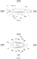
- FIG. 2 is a side view showing major components of the flight vehicle 1 of FIG. 1 .
- FIG. 3 is a plan view showing major components of the flight vehicle 1 of FIG. 1 .
- the top portion 13 of the body 2 includes a flat top surface 13a extending horizontally.
- An upper opening 13b through which the rotor shaft 8 extends is defined on the top surface 13a.
- the disc-shaped rotor head 16 is located at the upper side of the top surface 13a.
- the top portion 13 in the present embodiment is longer in the front-rear direction than in the left-right direction.
- the top portion 13 has a symmetrical shape in the left-right direction in a plan view.
- the top portion 13 has a streamline shape extending in the front-rear direction in a plan view.
- the shape of the top portion 13 is not limited to this. However, especially the shape of the top portion 13 which tapers toward the rear side hardly inhibits the flow generated by a pair of plate structures 30 of the present disclosure as compared to the other shapes. Therefore, this shape is suitably applicable to the pair of plate structures 30.
- the rotor shaft 8 projects upward from an inside of the body 2 through the upper opening 13b.
- the rotor head 16 is connected to the rotor shaft 8 at the upper side of the body 2.
- the top surface 13a is opposed to a lower surface 16b of the rotor head 16 in the upper-lower direction.
- the pair of plate structures 30 projecting upward from the top surface 13a are located at the top portion 13.
- the pair of plate structures 30 are separately located at the left and right sides of the rotor shaft 8.
- One of the pair of plate structures 30 extends in the front-rear direction at the right side of the rotor shaft 8.
- the other of the pair of plate structures 30 extends in the front-rear direction at the left side of the rotor shaft 8.
- the height of each plate structure 30 in the upper-lower direction is smaller than a distance between the top surface 13a and the rotor head 16 in the upper-lower direction.
- the upper end of each plate structure 30 is located lower than the lower surface 16b of the rotor head 16.
- the lower surface 16b of the rotor head 16 is a surface which is a lower contour of the rotor head 16 and faces downward.
- the right plate structure 30 and the left plate structure 30 are located symmetrically in the left-right direction with respect to a virtual vertical surface which extends in the front-rear direction through the axis of the rotor shaft 8.
- Each of the pair of plate structures 30 is a plate extending in the front-rear direction and including main surfaces facing in the left-right direction.
- Each plate structure 30 includes a front end 30a, a rear end 30b, an inner surface 30c facing inward in the left-right direction, and an outer surface 30d facing outward in the left-right direction.
- the pair of plate structures 30 in the present embodiment extend along left-right direction outer edges of the top surface 13a of the top portion 13.
- Each plate structure 30 in the present embodiment has a substantially rectangular shape in a side view. Specifically, in a side view, the front end of the plate structure 30 has a tapered shape including a diagonal ridgeline extending from the upper side to the lower side. The rear end 30b of the plate structure 30 extends in a direction perpendicular to the top surface 13a. Moreover, the thickness of the plate structure 30 in the present embodiment is, for example, constant. However, the plate structure 30 is not limited to this and may adopt various shapes. For example, the thickness of the plate structure 30 may change in the front-rear direction. To be specific, the position of the inner surface 30c of the plate structure 30 and the position of the outer surface 30d of the plate structure 30 in a plan view may be independently determined.
- the front ends 30a of the pair of plate structures 30 are located away from each other in the left-right direction.
- the rear ends 30b of the pair of plate structures 30 are located away from each other in the left-right direction.
- a distance L1 between the front ends 30a of the pair of plate structures 30 in the left-right direction is longer than a distance L2 between the rear ends 30b of the pair of plate structures 30 in the left-right direction.
- the front ends 30a of the plate structures 30 are located behind a front end of the top surface 13a.
- the front ends 30a of the plate structures 30 are located in front of the rotor shaft 8.
- the rear ends 30b of the plate structures 30 are located in front of a rear end of the top surface 13a.
- the rear ends 30b of the plate structures 30 are located behind the rotor shaft 8.
- the top portion 13 includes a rear portion 13c.
- the rear portion 13c is located behind the rear ends 30b of the plate structures 30.
- the rear portion 13c of the top portion 13 has a shape that tapers toward the rear side.
- the rear ends 30b of the plate structures 30 are located in front of a rear end 16a of the rotation trajectory of the radially outer end of the rotor head 16.
- the front ends 30a of the plate structures 30 are located behind the front end of the rotor head 16.
- the front ends 30a of the plate structures 30 may be located in front of the front end of the rotor head 16. At least a part of each plate structure 30 may overlap the rotor head 16 in a plan view.
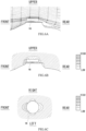
- FIG. 4 is a plan view for explaining air flow around the plate structures 30 of FIG. 3 during forward flight of the flight vehicle 1.
- FIG. 5 is a rear view for explaining the air flow around the plate structures 30 of FIG. 4 during the forward flight of the flight vehicle 1.
- the inner surface 30c of each plate structure 30 diagonally extends toward an inside in the left-right direction and the rear side.
- the outer surface 30d of each plate structure 30 diagonally extends toward the inside in the left-right direction and the rear side.
- each plate structure 30 has an angle of attack that is not zero with respect to a flow field around the plate structure 30.
- the plate structure 30 in the present embodiment has an arch shape projecting outward in the left-right direction.
- the plate structure 30 has a linear shape in FIG. 4 . To be specific, below-described effects can be obtained even when each plate structure 30 has the linear shape shown in FIG. 4 .
- each plate structure 30 In the flow field around each plate structure 30 during the forward flight of the flight vehicle 1, a stagnation point P is generated on the inner surface 30c of the plate structure 30, and pressure at a side where the inner surface 30c of the plate structure 30 is located becomes higher than pressure at a side where the outer surface 30d of the plate structure 30 is located. Moreover, in the flow field around the plate structure 30 during the forward flight of the flight vehicle 1, the flow of the air along the outer surface 30d of the plate structure 30 is made to turn diagonally relative to the front-rear direction, and this increases the flow velocity. As a result, the pressure at the side where the outer surface 30d of the plate structure 30 is located becomes low. As above, each plate structure 30 has such a shape that during the forward flight, the pressure at the side where the outer surface 30d is located becomes lower than the pressure at the side where the inner surface 30c is located.
- the air having entered between the pair of plate structures 30 from the front side during the forward flight of the flight vehicle 1 flows from the side where the inner surface 30c of each plate structure 30 is located to the side where the outer surface 30d of the plate structure 30 is located, over the upper end of the plate structure 30 in accordance with the pressure difference between the pressure at the side where the inner surface 30c of the plate structure 30 is located and the pressure at the side where the outer surface 30d of the plate structure 30 is located.
- the air flow having flowed through the plate structure 30 generates a vertical vortex V in which the air flows from an outside of the plate structure 30 through a lower side of the plate structure 30 and returns to an inside of the plate structure 30.
- the air of the vertical vortex V induces the flow from a region located inside the plate structure 30 in the left-right direction to the upper side. This flow passes through a wake region W of the rotor head 16. This suppresses a case where the airflow attaches to the rotor head 16 and flows around the rotor head 16 to the rear side. As a result, a pressure decrease of the wake region W of the rotor head 16 is suppressed.
- the distance L2 between the rear ends 30b of the pair of plate structures 30 in the left-right direction is a value that is twice or more and six times or less a maximum height H of the plate structure 30 in the upper-lower direction.
- a radius of the vertical vortex V which is generated by the plate structure 30 and may flow through the wake region W is represented by R, and a length of the plate structure 30 in the front-rear direction is represented by L.
- the radius R is regarded as being substantially equal to the maximum height H.
- the radius R of the vertical vortex V may be defined as a curvature radius of an outer edge of a region where vorticity exists.
- the radius R of the vertical vortex V may be defined as a curvature radius of a line whose speed in a rotational direction is the highest.
- the rear portion 13c of the top portion 13 has a shape that tapers toward the rear side. Therefore, the vertical vortexes V behind the plate structures 30 hardly hit the top portion 13. As a result, the flow in which the vertical vortexes V move upward can be promoted.
- the positions of the rear ends 30b of the plate structures 30 in the front-rear direction may be the same as or may be located in front of the position of the rear end of the top portion 13 in the front-rear direction.
- Example that is a result of simulation in which the flow field around the flight vehicle including the plate structures 30 is analyzed; and Comparative Example that is a result of simulation in which the flow field around a conventional flight vehicle not including the plate structures 30 is analyzed.
- Used in the present analysis is a model in which as the main rotary wing, the rotor blades 17 are omitted, and only the disc-shaped rotor head 16 is included.
- the flow field is locally and momentarily disturbed by the rotor blades, but the global flow field including the circumference of the rotor head 16 is not influenced by the rotor blades.
- the flow filed converges to the same flow field as when there is no rotor blade. Therefore, even when there is the rotor blade, the flow field around the rotor head 16 becomes the same as the flow field when there is no rotor blade, from the viewpoint of time average.
- FIG. 6A is a side view showing an analytical result of a streamline distribution of Comparative Example.
- FIG. 6B is a side view showing an analytical result of a pressure distribution of Comparative Example.
- FIG. 6C is a plan view showing an analytical result of the pressure distribution of Comparative Example.
- FIG. 6A in Comparative Example, there is the generation of typical wake behind the rotor head 16.
- FIGS. 6B and 6C in Comparative Example, a large pressure decrease occurs in the wake region of the rotor head 16. Therefore, pressure resistance of the rotor head 16 with respect to the forward flight is large.
- FIG. 7A is a side view showing the analytical result of the streamline distribution of Example.
- FIG. 7B is a side view showing the analytical result of the pressure distribution of Example.
- FIG. 7C is a plan view showing the analytical result of the pressure distribution of Example.
- the air flow having flowed through the plate structures 30 to the rear side flows diagonally upward and flows through the wake region of the rotor head 16.
- a large pressure decrease does not occur in the wake region of the rotor head 16. Therefore, the pressure resistance of the rotor head 16 with respect to the forward flight is small.
- each plate structure 30 has such a shape that during the forward flight of the flight vehicle 1, the pressure at the side where the outer surface 30d is located becomes lower than the pressure at the side where the inner surface 30c is located. Therefore, in a period from when the air has entered between the pair of plate structures 30 until when the air flows out to the rear side of the plate structures 30, the air having entered between the pair of plate structures 30 flows from the side where the inner surfaces 30c of the plate structures 30 are located, over the upper ends of the plate structures 30 in accordance with the pressure difference, and reaches the side where the left outer surface 30d of the plate structure 30 is located and the side where the right outer surface 30d of the plate structure 30 is located, and thereafter, the air flows to the rear side of the plate structures.
- the air flow having flowed through the plate structure 30 when viewed in the front-rear direction, the air flow having flowed through the plate structure 30 generates the vertical vortex V in which the air flows from the outside of the plate structure 30 through the lower side of the plate structure 30 and returns to the inside of the plate structure 30. Therefore, when the air of the vertical vortex V flows upward from the region located at the inside of the plate structure 30 in the left-right direction, the pressure decrease of the wake region W of the rotor head 16 is suppressed. As a result, the pressure resistance of the rotor head 16 can be reduced.
- each plate structure 30 diagonally extends toward the inside in the left-right direction and the rear side. Therefore, in the flow field around the plate structure 30 during the forward flight of the flight vehicle 1, the stagnation point P is generated on the inner surface 30c of the plate structure 30, and the pressure at the side where the inner surface 30c of the plate structure 30 is located becomes higher than the pressure at the side where the outer surface 30d of the plate structure 30 is located. Thus, the generation of the vertical vortex V is promoted, and the pressure resistance of the rotor head 16 can be reduced.
- each plate structure 30 diagonally extends toward the inside in the left-right direction and the rear side. Therefore, in the flow field around the plate structure 30 during the forward flight of the flight vehicle 1, the flow of the air along the outer surface 30d of the plate structure 30 is made to turn diagonally, and this increases the flow velocity. As a result, the pressure at the side where the outer surface 30d of the plate structure 30 is located becomes low. Thus, the generation of the vertical vortex V is promoted, and the pressure resistance of the rotor head 16 can be reduced.
- the rear ends 30b of the pair of plate structures 30 are located in front of the rotor head 16 or the rear end 16a of a rotation trajectory T of the radially outer end of the rotor head 16. Therefore, the vertical vortex V moves with the rearward flow and easily and appropriately flows to the wake region W of the rotor head 16.
- the distance L2 between the rear ends of the pair of plate structures 30 in the left-right direction is twice or more the maximum height H of the plate structure 30
- the interference between the vertical vortex V generated by the right plate structure 30 and the vertical vortex V generated by the left plate structure 30 is reduced.
- the upward flow of the vertical vortex V can be promoted.
- the distance L2 between the rear ends 30b of the plate structures 30 in the left-right direction is four times or less the maximum height of the plate structure 30, the flow of the vertical vortex V toward the wake region of the rotor head 16 can be improved.
- the rear portion 13c of the top portion 13 has a shape that tapers toward the rear side. Therefore, the vertical vortexes V behind the plate structures 30 hardly hit the top portion 13 of the body 2. As a result, the upward flow of the vertical vortexes V can be promoted.
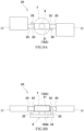
- FIG. 8A is a plan view showing a first modified example of the rotor head 16 of FIG. 1 and its vicinity.
- FIG. 8B is a side view showing the rotor head 16A of FIG. 8A and its vicinity.
- a main rotary wing 3A of the rotor head 16A is of a variable pitch type and does not include a hub cap.
- the main rotary wing 3A includes a hub 21, coupling bodies 22, flapping hinges 23, and rotor blades 17.
- the hub 21 is externally fitted to an upper portion of the rotor shaft 8 and rotates together with the rotor shaft 8.
- Each coupling body 22 connects the rotor blade 17 to the hub 21.
- One end portion of the coupling body 22 is coupled to the hub 21 so as to be able to perform a pitching operation.
- the rotor blade 17 is connected to the other end portion of the coupling body 22 through the flapping hinge 23.
- a swash plate 24 is located under the hub 21.
- the coupling bodies 22 are coupled to the swash plate 24 through pitch links 25.
- the rotor head 16A of the first modified example is the hub 21.
- the hub 21 performs only the rotation around the axis of the rotor shaft 8 during the flight.
- the coupling bodies 22, the flapping hinges 23, the swash plate 24, and the pitch links 25 perform other operations in addition to the rotation around the axis of the rotor shaft 8 during the flight. Therefore, these components are not included in the rotor head 16A.
- a two-dot chain line in FIGS. 8A and 8B shows the rotation trajectory T of the rotor head 16A.
- a lower surface 16Ab of the rotor head 16A of the first modified example is a main surface, which faces downward, of the rotation trajectory T of the hub 21.
- FIG. 9A is a plan view showing a second modified example of the rotor head 16 of FIG. 1 and its vicinity.
- FIG. 9B is a side view showing a rotor head 16B of FIG. 9A and its vicinity.
- the main rotary wing 3B of the rotor head 16B is of a variable pitch type and includes the hub cap.
- the main rotary wing 3B includes the hub 21, the coupling bodies 22, the flapping hinges 23, the rotor blades 17, and a hub cap 26.
- the hub 21, the coupling bodies 22, the flapping hinges 23, and the rotor blades 17 are the same as those of the first modified example.
- the hub cap 26 is fixed to the hub 21 so as to cover the hub 21.
- the rotor head 16B is an assembly including the hub 21 and the hub cap 26.
- the hub 21 performs only the rotation around the axis of the rotor shaft 8 during the flight.
- a two-dot chain line in FIGS. 9A and 9B shows the rotation trajectory T of the rotor head 16B.
- a lower surface 16Bb of the rotor head 16B of the second modified example is a main surface, which faces downward, of the rotation trajectory T of the hub 21.
- FIG. 10A is a plan view showing a third modified example of the rotor head 16 of FIG. 1 and its vicinity.
- FIG. 10B is a side view showing the rotor head 16C of FIG. 10A and its vicinity.
- the main rotary wing 3 of the rotor head 16C is of a fixed pitch type.
- the main rotary wing 3C includes the hub 21 and the rotor blades 17.
- the hub 21 is externally fitted to the upper portion of the rotor shaft 8 and rotates together with the rotor shaft 8.
- the rotor blades 17 are fixed to the hub 21.
- the rotor head 16C of the third modified example is the hub 21.
- the hub 21 performs only the rotation around the axis of the rotor shaft 8 during the flight.
- a two-dot chain line in FIGS. 10A and 10B is the rotation trajectory T of the rotor head 16C.
- a lower surface 16Cb of the rotor head 16C of the third modified example is a main surface, which faces downward, of the rotation trajectory T of the hub 21.
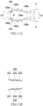
- FIG. 11A is a plan view showing a first modified example of the plate structures 30 of FIG. 3 .
- each of plate structures 130 of the first modified example has an arch shape that projects outward in the left-right direction.
- Each of rear half portions of the pair of plate structures 130 diagonally extends toward the inside in the left-right direction and the rear side.
- a distance L3 between front ends 130a of the pair of plate structures 130 in the left-right direction is equal to a distance L4 between rear ends 130b of the pair of plate structures 130 in the left-right direction.
- the angle of attack of each plate structure 130 is zero.
- the plate structure 130 has camber in a plan view. Therefore, in the flow field around the plate structure 130 during the forward flight, circulation occurs in terms of fluid dynamics, and the stagnation point P is generated on an inner surface 130c of the plate structure 130. Therefore, the pressure at a side where the inner surface 130c of the plate structure 130 is located becomes higher than the pressure at a side where an outer surface 130d of the plate structure 130 is located.
- the air having entered between the pair of plate structures 130 from the front side during the forward flight flows from the side where the inner surface 130c of each plate structure 130 is located to the side where the outer surface 130d of the plate structure 130 is located, over the upper end of the plate structure 130 in accordance with the pressure difference around the plate structure 130.
- the vertical vortexes V are generated.
- the pressure resistance of the rotor head 16 is reduced.
- each plate structure 130 of the first modified example described above does not have to be zero.
- the distance L3 between the front ends 130a of the pair of plate structures 130 in the left-right direction may be larger than the distance L4 between the rear ends 130b of the pair of plate structures 130 in the left-right direction.
- FIG. 11B is a plan view showing a second modified example of the plate structures 30 of FIG. 3 .
- each of plate structures 230 of the second modified example is an assembly of plate elements 231 to 233 adjacently lined up.
- the assembly of the plate elements 231 to 233 has a substantially plate shape as a whole.
- each of the plate elements 231 to 233 diagonally extends toward the inside in the left-right direction and the rear side.
- the plate elements 231 to 233 are located so as to be displaced from each other in the front-rear direction.
- the plate structure 230 diagonally extends toward the inside in the left-right direction and the rear side as a whole.
- the plate structure 230 is divided into three plate elements 231 to 233.
- the plate structure 230 may be divided into two plate elements or four or more plate elements.
- the shape of the plate structure in a side view is a rectangular shape extending in the front-rear direction.
- the shape of the plate structure in a side view may be a trapezoidal shape, a triangular shape, a semicircular shape, or the like.
- the plate structure is vertically attached to the top surface 13a and projects from the body 2 in the vertical direction.
- the direction in which the plate structure projects from the body 2 is not limited to this.
- the plate structure may be inclined relative to the vertical direction in a rear view in accordance with, for example, the angle of the top surface 13a.
- the plate structure may include a hole or a recess for weight reduction.
- the plate structure may have an airfoil shape in a plan view.
- the plate structure 30 may be located at the upper side of the top portion 13 and fixed to the outer surface of the top portion 13.
- the plate structure may be located at the upper side of the top surface 13a with a gap and supported by the top portion 13 through a bracket.
Landscapes
- Engineering & Computer Science (AREA)
- Aviation & Aerospace Engineering (AREA)
- Mechanical Engineering (AREA)
- Structures Of Non-Positive Displacement Pumps (AREA)
- Toys (AREA)
- Turbine Rotor Nozzle Sealing (AREA)
Abstract
Description
- The present disclosure relates to a flight vehicle including a rotary wing.
- Air resistance is generated when a rotary wing flight vehicle, such as a helicopter, performs forward flight. The air resistance limits a maximum speed and deteriorates fuel efficiency.
PTL 1 discloses a fairing that reduces resistance generated at a rotor shaft projecting upward from a body of a helicopter. The fairing covers the rotor shaft in a space between the body and a rotor head. Moreover, the fairing has a streamline shape that tapers toward a rear side. - PTL 1:
U.S. Patent No. 10,232,929 - The resistance when the rotary wing flight vehicle performs the forward flight may be generated due to various factors. The present inventors have focused on the fact that: an airflow attaches to the rotor head and flows around the rotor head to a rear side, and this generates a wake region; and pressure resistance of the rotor head which is generated by the wake region becomes resistance of the flight vehicle.
- An object of the present disclosure is to reduce pressure resistance of a rotor head of a flight vehicle.
- A flight vehicle according to one aspect of the present disclosure includes: a body; a rotor shaft projecting upward from the body; a rotor head connected to the rotor shaft at an upper side of the body; and a pair of plate structures located at the upper side of the body and extending in a front-rear direction at right and left sides of the rotor shaft. Each of the pair of plate structures includes a front end, a rear end, an inner surface facing inward in a left-right direction, and an outer surface facing outward in the left-right direction. The front ends of the pair of plate structures are located away from each other in the left-right direction. The rear ends of the pair of plate structures are located away from each other in the left-right direction. Each of the pair of plate structures has such a shape that during forward flight, pressure at a side where the outer surface is located becomes lower than pressure at a side where the inner surface is located.
- According to one aspect of the present disclosure, air having entered between the pair of plate structures from the front side during the forward flight of the flight vehicle flows to a rear side of the pair of plate structures. In a period from when the air has entered between the pair of plate structures until when the air flows out to the rear side of the plate structures, the air having entered between the pair of plate structures flows from the side where the inner surfaces of the plate structures are located, over upper ends of the plate structures in accordance with a pressure difference, and reaches the side where the left outer surface of the plate structure is located and the side where the right outer surface of the plate structure is located, and thereafter, the air flows to the rear side of the plate structures. Thus, when viewed in the front-rear direction, the air flow having flowed through the plate structure generates a vertical vortex in which the air flows from an outside of the plate structure through a lower side of the plate structure and returns to an inside of the plate structure. When the air of this vortex flows upward from a region located at the inside of the plate structure in the left-right direction, a pressure decrease of the wake region of the rotor head is suppressed. As a result, pressure resistance of the rotor head can be reduced.
-
-
FIG. 1 is a perspective view showing a flight vehicle according to an embodiment. -
FIG. 2 is a side view showing major components of the flight vehicle ofFIG. 1 . -
FIG. 3 is a plan view showing major components of the flight vehicle ofFIG. 1 . -
FIG. 4 is a plan view for explaining an air flow around plate structures ofFIG. 3 . -
FIG. 5 is a rear view for explaining the air flow around the plate structures ofFIG. 4 . -
FIG. 6A is a side view showing an analytical result of a streamline distribution of Comparative Example. -
FIG. 6B is a side view showing an analytical result of a pressure distribution of Comparative Example. -
FIG. 6C is a plan view showing the analytical result of the pressure distribution of Comparative Example. -
FIG. 7A is a side view showing the analytical result of the streamline distribution of Example. -
FIG. 7B is a side view showing the analytical result of the pressure distribution of Example. -
FIG. 7C is a plan view showing the analytical result of the pressure distribution of Example. -
FIG. 8A is a plan view showing a first modified example of a rotor head ofFIG. 1 and its vicinity. -
FIG. 8B is a side view showing the rotor head ofFIG. 8A and its vicinity. -
FIG. 9A is a plan view showing a second modified example of the rotor head ofFIG. 1 and its vicinity. -
FIG. 9B is a side view showing the rotor head ofFIG. 9A and its vicinity. -
FIG. 10A is a plan view showing a third modified example of the rotor head ofFIG. 1 and its vicinity. -
FIG. 10B is a side view showing the rotor head ofFIG. 10A and its vicinity. -
FIG. 11A is a plan view showing a first modified example of the plate structures ofFIG. 3 . -
FIG. 11B is a plan view showing a second modified example of the plate structures ofFIG. 3 . - Hereinafter, an embodiment will be described with reference to the drawings.
-
FIG. 1 is a perspective view showing aflight vehicle 1 according to the embodiment. As shown inFIG. 1 , theflight vehicle 1 is a rotary wing flight vehicle including a mainrotary wing 3. As one example, theflight vehicle 1 is a compound helicopter including abody 2, the mainrotary wing 3, a pair ofmain wings 4, a pair ofpropellers 5, a pair ofhorizontal empennages 6, and avertical tail 7. Theflight vehicle 1 may be a general helicopter that is not the compound helicopter. Moreover, the number of main rotary wings may be two or more. - In the description of the present embodiment, a direction in which a
rotor shaft 8 that connects thebody 2 and arotor head 16 of the mainrotary wing 3 extends when theflight vehicle 1 is in a landed state is referred to as an upper-lower direction of theflight vehicle 1. In this case, one side of thebody 2 where therotor head 16 is located is referred to as an upper side. Moreover, a surface orthogonal to the upper-lower direction is a horizontal surface. In this case, directions in the horizontal surface are horizontal directions. In addition, in the horizontal surface, a direction in which the pair ofmain wings 4 extend is referred to as a left-right direction of theflight vehicle 1, and a direction orthogonal to the left-right direction is referred to as a front-rear direction. In this case, one side of a center of thebody 2 where the pair ofhorizontal empennages 6 and thevertical tail 7 are located is referred to as a rear side, and its opposite side is a front side. - The
body 2 includes afront portion 11, anintermediate portion 12, atop portion 13, and arear portion 14. Thefront portion 11 of thebody 2 has a shape that tapers toward the front side. The pair ofmain wings 4 projecting to the left and right sides from theintermediate portion 12 are connected to theintermediate portion 12 of thebody 2.Propellers 5 are located at the respectivemain wings 4. Thetop portion 13 of thebody 2 has a columnar shape and projects upward from theintermediate portion 12. Therear portion 14 of thebody 2 has a shape that tapers toward the rear side. Thevertical tail 7 and the pair ofhorizontal empennages 6 are connected to therear portion 14 of thebody 2. Thevertical tail 7 projects upward from therear portion 14. The pair ofhorizontal empennages 6 project from therear portion 14 to the left and right sides. - The main
rotary wing 3 is located at the upper side of thetop portion 13 of thebody 2. As shown inFIG. 2 , the mainrotary wing 3 is rotated by therotor shaft 8 to generate lift. Therotor shaft 8 is driven by a prime mover located inside thebody 2. The mainrotary wing 3 includes therotor head 16 androtor blades 17. Therotor head 16 is connected to therotor shaft 8 projecting upward from thetop portion 13. Therotor blades 17 radially project from therotor head 16 in substantially the horizontal directions. - The
rotor head 16 does not perform parallel displacement or rotation displacement in a fixed coordinate system of therotor shaft 8. In other words, therotor head 16 performs only the rotation around an axis of therotor shaft 8 during the flight. - The
rotor head 16 in the present embodiment has a disc shape. Therotor head 16 has a circular shape in a plan view. Therotor head 16 includes, for example, a hub and a hub cap. The hub is connected to therotor shaft 8. The hub cap has a disc shape covering the entire hub. An outer shape of therotor head 16 is an outer shape of the hub cap. When the rotor head has a non-circular shape in a plan view, a rotation trajectory of a radially outer end of the rotor head is assumed as the outer shape of therotor head 16 in terms of fluid dynamics. When the actual rotor head has a circular shape in a plan view, the rotation trajectory of the radially outer end of the rotor head coincides with the outer shape of theactual rotor head 16. -
FIG. 2 is a side view showing major components of theflight vehicle 1 ofFIG. 1 .FIG. 3 is a plan view showing major components of theflight vehicle 1 ofFIG. 1 . As shown inFIGS. 2 and 3 , thetop portion 13 of thebody 2 includes a flattop surface 13a extending horizontally. Anupper opening 13b through which therotor shaft 8 extends is defined on thetop surface 13a. The disc-shapedrotor head 16 is located at the upper side of thetop surface 13a. Thetop portion 13 in the present embodiment is longer in the front-rear direction than in the left-right direction. Thetop portion 13 has a symmetrical shape in the left-right direction in a plan view. Thetop portion 13 has a streamline shape extending in the front-rear direction in a plan view. - The shape of the
top portion 13 is not limited to this. However, especially the shape of thetop portion 13 which tapers toward the rear side hardly inhibits the flow generated by a pair ofplate structures 30 of the present disclosure as compared to the other shapes. Therefore, this shape is suitably applicable to the pair ofplate structures 30. Therotor shaft 8 projects upward from an inside of thebody 2 through theupper opening 13b. Therotor head 16 is connected to therotor shaft 8 at the upper side of thebody 2. Thetop surface 13a is opposed to alower surface 16b of therotor head 16 in the upper-lower direction. - The pair of
plate structures 30 projecting upward from thetop surface 13a are located at thetop portion 13. The pair ofplate structures 30 are separately located at the left and right sides of therotor shaft 8. One of the pair ofplate structures 30 extends in the front-rear direction at the right side of therotor shaft 8. The other of the pair ofplate structures 30 extends in the front-rear direction at the left side of therotor shaft 8. The height of eachplate structure 30 in the upper-lower direction is smaller than a distance between thetop surface 13a and therotor head 16 in the upper-lower direction. To be specific, the upper end of eachplate structure 30 is located lower than thelower surface 16b of therotor head 16. Thelower surface 16b of therotor head 16 is a surface which is a lower contour of therotor head 16 and faces downward. Theright plate structure 30 and theleft plate structure 30 are located symmetrically in the left-right direction with respect to a virtual vertical surface which extends in the front-rear direction through the axis of therotor shaft 8. - Each of the pair of
plate structures 30 is a plate extending in the front-rear direction and including main surfaces facing in the left-right direction. Eachplate structure 30 includes afront end 30a, arear end 30b, aninner surface 30c facing inward in the left-right direction, and anouter surface 30d facing outward in the left-right direction. The pair ofplate structures 30 in the present embodiment extend along left-right direction outer edges of thetop surface 13a of thetop portion 13. - Each
plate structure 30 in the present embodiment has a substantially rectangular shape in a side view. Specifically, in a side view, the front end of theplate structure 30 has a tapered shape including a diagonal ridgeline extending from the upper side to the lower side. Therear end 30b of theplate structure 30 extends in a direction perpendicular to thetop surface 13a. Moreover, the thickness of theplate structure 30 in the present embodiment is, for example, constant. However, theplate structure 30 is not limited to this and may adopt various shapes. For example, the thickness of theplate structure 30 may change in the front-rear direction. To be specific, the position of theinner surface 30c of theplate structure 30 and the position of theouter surface 30d of theplate structure 30 in a plan view may be independently determined. - The front ends 30a of the pair of
plate structures 30 are located away from each other in the left-right direction. The rear ends 30b of the pair ofplate structures 30 are located away from each other in the left-right direction. A distance L1 between thefront ends 30a of the pair ofplate structures 30 in the left-right direction is longer than a distance L2 between therear ends 30b of the pair ofplate structures 30 in the left-right direction. - The front ends 30a of the
plate structures 30 are located behind a front end of thetop surface 13a. The front ends 30a of theplate structures 30 are located in front of therotor shaft 8. The rear ends 30b of theplate structures 30 are located in front of a rear end of thetop surface 13a. The rear ends 30b of theplate structures 30 are located behind therotor shaft 8. Thetop portion 13 includes arear portion 13c. Therear portion 13c is located behind the rear ends 30b of theplate structures 30. Therear portion 13c of thetop portion 13 has a shape that tapers toward the rear side. - The rear ends 30b of the
plate structures 30 are located in front of arear end 16a of the rotation trajectory of the radially outer end of therotor head 16. In the present embodiment, the front ends 30a of theplate structures 30 are located behind the front end of therotor head 16. However, the front ends 30a of theplate structures 30 may be located in front of the front end of therotor head 16. At least a part of eachplate structure 30 may overlap therotor head 16 in a plan view. -
FIG. 4 is a plan view for explaining air flow around theplate structures 30 ofFIG. 3 during forward flight of theflight vehicle 1.FIG. 5 is a rear view for explaining the air flow around theplate structures 30 ofFIG. 4 during the forward flight of theflight vehicle 1. As shown inFIGS. 4 and 5 , theinner surface 30c of eachplate structure 30 diagonally extends toward an inside in the left-right direction and the rear side. Theouter surface 30d of eachplate structure 30 diagonally extends toward the inside in the left-right direction and the rear side. - In the present embodiment, the thickness of each
plate structure 30 is constant. Therefore, theentire plate structure 30 diagonally extends toward the inside in the left-right direction and the rear side. During the forward flight of theflight vehicle 1, eachplate structure 30 has an angle of attack that is not zero with respect to a flow field around theplate structure 30. Theplate structure 30 in the present embodiment has an arch shape projecting outward in the left-right direction. However, for ease of explanation, theplate structure 30 has a linear shape inFIG. 4 . To be specific, below-described effects can be obtained even when eachplate structure 30 has the linear shape shown inFIG. 4 . - In the flow field around each
plate structure 30 during the forward flight of theflight vehicle 1, a stagnation point P is generated on theinner surface 30c of theplate structure 30, and pressure at a side where theinner surface 30c of theplate structure 30 is located becomes higher than pressure at a side where theouter surface 30d of theplate structure 30 is located. Moreover, in the flow field around theplate structure 30 during the forward flight of theflight vehicle 1, the flow of the air along theouter surface 30d of theplate structure 30 is made to turn diagonally relative to the front-rear direction, and this increases the flow velocity. As a result, the pressure at the side where theouter surface 30d of theplate structure 30 is located becomes low. As above, eachplate structure 30 has such a shape that during the forward flight, the pressure at the side where theouter surface 30d is located becomes lower than the pressure at the side where theinner surface 30c is located. - The air having entered between the pair of
plate structures 30 from the front side during the forward flight of theflight vehicle 1 flows from the side where theinner surface 30c of eachplate structure 30 is located to the side where theouter surface 30d of theplate structure 30 is located, over the upper end of theplate structure 30 in accordance with the pressure difference between the pressure at the side where theinner surface 30c of theplate structure 30 is located and the pressure at the side where theouter surface 30d of theplate structure 30 is located. Thus, when viewed in the front-rear direction, the air flow having flowed through theplate structure 30 generates a vertical vortex V in which the air flows from an outside of theplate structure 30 through a lower side of theplate structure 30 and returns to an inside of theplate structure 30. The air of the vertical vortex V induces the flow from a region located inside theplate structure 30 in the left-right direction to the upper side. This flow passes through a wake region W of therotor head 16. This suppresses a case where the airflow attaches to therotor head 16 and flows around therotor head 16 to the rear side. As a result, a pressure decrease of the wake region W of therotor head 16 is suppressed. - The distance L2 between the
rear ends 30b of the pair ofplate structures 30 in the left-right direction is a value that is twice or more and six times or less a maximum height H of theplate structure 30 in the upper-lower direction. A radius of the vertical vortex V which is generated by theplate structure 30 and may flow through the wake region W is represented by R, and a length of theplate structure 30 in the front-rear direction is represented by L. In this case, when an aspect ratio (= H/L) of theplate structure 30 is smaller than one, the radius R is regarded as being substantially equal to the maximum height H. When the aspect ratio (= H/L) of theplate structure 30 is one or more, the radius R is empirically regarded as being equal to the length L, and the range of the distance L2 is defined as being twice or more and six times or less the length L by using "R = L." - The radius R of the vertical vortex V may be defined as a curvature radius of an outer edge of a region where vorticity exists. For example, in a Rankine vortex model, the radius R of the vertical vortex V may be defined as a curvature radius of a line whose speed in a rotational direction is the highest. When the distance L2 is twice or more the radius R, interference between the vertical vortexes V generated behind the left and
right plate structures 30 can be suppressed, i.e., a loss generated by collision between vortexes in vortex rotation directions can be suppressed. Moreover, when the distance L2 is six times or less the radius R, the flow in which the left and right vertical vortexes V move upward can be suitably induced. As a result, the flow of the vertical vortexes V can suitably reach the wake region W of therotor head 16. - Moreover, as shown in
FIG. 3 , therear portion 13c of thetop portion 13 has a shape that tapers toward the rear side. Therefore, the vertical vortexes V behind theplate structures 30 hardly hit thetop portion 13. As a result, the flow in which the vertical vortexes V move upward can be promoted. The positions of the rear ends 30b of theplate structures 30 in the front-rear direction may be the same as or may be located in front of the position of the rear end of thetop portion 13 in the front-rear direction. - The following will describe: Example that is a result of simulation in which the flow field around the flight vehicle including the
plate structures 30 is analyzed; and Comparative Example that is a result of simulation in which the flow field around a conventional flight vehicle not including theplate structures 30 is analyzed. - Used in the present analysis is a model in which as the main rotary wing, the
rotor blades 17 are omitted, and only the disc-shapedrotor head 16 is included. According to the actual main rotary wing, the flow field is locally and momentarily disturbed by the rotor blades, but the global flow field including the circumference of therotor head 16 is not influenced by the rotor blades. Immediately after the rotor blade passes through the flow field in the vicinity of therotor head 16, the flow filed converges to the same flow field as when there is no rotor blade. Therefore, even when there is the rotor blade, the flow field around therotor head 16 becomes the same as the flow field when there is no rotor blade, from the viewpoint of time average. -
FIG. 6A is a side view showing an analytical result of a streamline distribution of Comparative Example.FIG. 6B is a side view showing an analytical result of a pressure distribution of Comparative Example.FIG. 6C is a plan view showing an analytical result of the pressure distribution of Comparative Example. As shown inFIG. 6A , in Comparative Example, there is the generation of typical wake behind therotor head 16. As shown inFIGS. 6B and 6C , in Comparative Example, a large pressure decrease occurs in the wake region of therotor head 16. Therefore, pressure resistance of therotor head 16 with respect to the forward flight is large. -
FIG. 7A is a side view showing the analytical result of the streamline distribution of Example.FIG. 7B is a side view showing the analytical result of the pressure distribution of Example.FIG. 7C is a plan view showing the analytical result of the pressure distribution of Example. As shown inFIG. 7A , in Example, the air flow having flowed through theplate structures 30 to the rear side flows diagonally upward and flows through the wake region of therotor head 16. As shown inFIGS. 7B and 7C , in Example, a large pressure decrease does not occur in the wake region of therotor head 16. Therefore, the pressure resistance of therotor head 16 with respect to the forward flight is small. - According to the above-described configuration, each
plate structure 30 has such a shape that during the forward flight of theflight vehicle 1, the pressure at the side where theouter surface 30d is located becomes lower than the pressure at the side where theinner surface 30c is located. Therefore, in a period from when the air has entered between the pair ofplate structures 30 until when the air flows out to the rear side of theplate structures 30, the air having entered between the pair ofplate structures 30 flows from the side where theinner surfaces 30c of theplate structures 30 are located, over the upper ends of theplate structures 30 in accordance with the pressure difference, and reaches the side where the leftouter surface 30d of theplate structure 30 is located and the side where the rightouter surface 30d of theplate structure 30 is located, and thereafter, the air flows to the rear side of the plate structures. - Thus, when viewed in the front-rear direction, the air flow having flowed through the
plate structure 30 generates the vertical vortex V in which the air flows from the outside of theplate structure 30 through the lower side of theplate structure 30 and returns to the inside of theplate structure 30. Therefore, when the air of the vertical vortex V flows upward from the region located at the inside of theplate structure 30 in the left-right direction, the pressure decrease of the wake region W of therotor head 16 is suppressed. As a result, the pressure resistance of therotor head 16 can be reduced. - The
inner surface 30c of eachplate structure 30 diagonally extends toward the inside in the left-right direction and the rear side. Therefore, in the flow field around theplate structure 30 during the forward flight of theflight vehicle 1, the stagnation point P is generated on theinner surface 30c of theplate structure 30, and the pressure at the side where theinner surface 30c of theplate structure 30 is located becomes higher than the pressure at the side where theouter surface 30d of theplate structure 30 is located. Thus, the generation of the vertical vortex V is promoted, and the pressure resistance of therotor head 16 can be reduced. - The
outer surface 30d of eachplate structure 30 diagonally extends toward the inside in the left-right direction and the rear side. Therefore, in the flow field around theplate structure 30 during the forward flight of theflight vehicle 1, the flow of the air along theouter surface 30d of theplate structure 30 is made to turn diagonally, and this increases the flow velocity. As a result, the pressure at the side where theouter surface 30d of theplate structure 30 is located becomes low. Thus, the generation of the vertical vortex V is promoted, and the pressure resistance of therotor head 16 can be reduced. - The rear ends 30b of the pair of
plate structures 30 are located in front of therotor head 16 or therear end 16a of a rotation trajectory T of the radially outer end of therotor head 16. Therefore, the vertical vortex V moves with the rearward flow and easily and appropriately flows to the wake region W of therotor head 16. - When the distance L2 between the rear ends of the pair of
plate structures 30 in the left-right direction is twice or more the maximum height H of theplate structure 30, the interference between the vertical vortex V generated by theright plate structure 30 and the vertical vortex V generated by theleft plate structure 30 is reduced. As a result, the upward flow of the vertical vortex V can be promoted. When the distance L2 between therear ends 30b of theplate structures 30 in the left-right direction is four times or less the maximum height of theplate structure 30, the flow of the vertical vortex V toward the wake region of therotor head 16 can be improved. - The
rear portion 13c of thetop portion 13 has a shape that tapers toward the rear side. Therefore, the vertical vortexes V behind theplate structures 30 hardly hit thetop portion 13 of thebody 2. As a result, the upward flow of the vertical vortexes V can be promoted. -
FIG. 8A is a plan view showing a first modified example of therotor head 16 ofFIG. 1 and its vicinity.FIG. 8B is a side view showing therotor head 16A ofFIG. 8A and its vicinity. As shown inFIGS. 8A and 8B , a mainrotary wing 3A of therotor head 16A is of a variable pitch type and does not include a hub cap. The mainrotary wing 3A includes ahub 21,coupling bodies 22, flapping hinges 23, androtor blades 17. Thehub 21 is externally fitted to an upper portion of therotor shaft 8 and rotates together with therotor shaft 8. - Each
coupling body 22 connects therotor blade 17 to thehub 21. One end portion of thecoupling body 22 is coupled to thehub 21 so as to be able to perform a pitching operation. Therotor blade 17 is connected to the other end portion of thecoupling body 22 through the flappinghinge 23. Aswash plate 24 is located under thehub 21. Thecoupling bodies 22 are coupled to theswash plate 24 through pitch links 25. - The
rotor head 16A of the first modified example is thehub 21. Thehub 21 performs only the rotation around the axis of therotor shaft 8 during the flight. Thecoupling bodies 22, the flapping hinges 23, theswash plate 24, and the pitch links 25 perform other operations in addition to the rotation around the axis of therotor shaft 8 during the flight. Therefore, these components are not included in therotor head 16A. A two-dot chain line inFIGS. 8A and 8B shows the rotation trajectory T of therotor head 16A. Moreover, a lower surface 16Ab of therotor head 16A of the first modified example is a main surface, which faces downward, of the rotation trajectory T of thehub 21. -
FIG. 9A is a plan view showing a second modified example of therotor head 16 ofFIG. 1 and its vicinity.FIG. 9B is a side view showing arotor head 16B ofFIG. 9A and its vicinity. As shown inFIGS. 9A and 9B , the mainrotary wing 3B of therotor head 16B is of a variable pitch type and includes the hub cap. The mainrotary wing 3B includes thehub 21, thecoupling bodies 22, the flapping hinges 23, therotor blades 17, and ahub cap 26. Thehub 21, thecoupling bodies 22, the flapping hinges 23, and therotor blades 17 are the same as those of the first modified example. - The
hub cap 26 is fixed to thehub 21 so as to cover thehub 21. Therotor head 16B is an assembly including thehub 21 and thehub cap 26. Thehub 21 performs only the rotation around the axis of therotor shaft 8 during the flight. A two-dot chain line inFIGS. 9A and 9B shows the rotation trajectory T of therotor head 16B. Moreover, a lower surface 16Bb of therotor head 16B of the second modified example is a main surface, which faces downward, of the rotation trajectory T of thehub 21. -
FIG. 10A is a plan view showing a third modified example of therotor head 16 ofFIG. 1 and its vicinity.FIG. 10B is a side view showing therotor head 16C ofFIG. 10A and its vicinity. As shown inFIGS. 10A and 10B , the mainrotary wing 3 of therotor head 16C is of a fixed pitch type. The mainrotary wing 3C includes thehub 21 and therotor blades 17. Thehub 21 is externally fitted to the upper portion of therotor shaft 8 and rotates together with therotor shaft 8. - The
rotor blades 17 are fixed to thehub 21. Therotor head 16C of the third modified example is thehub 21. Thehub 21 performs only the rotation around the axis of therotor shaft 8 during the flight. A two-dot chain line inFIGS. 10A and 10B is the rotation trajectory T of therotor head 16C. Moreover, a lower surface 16Cb of therotor head 16C of the third modified example is a main surface, which faces downward, of the rotation trajectory T of thehub 21. -
FIG. 11A is a plan view showing a first modified example of theplate structures 30 ofFIG. 3 . As shown inFIG. 11A , each ofplate structures 130 of the first modified example has an arch shape that projects outward in the left-right direction. Each of rear half portions of the pair ofplate structures 130 diagonally extends toward the inside in the left-right direction and the rear side. A distance L3 betweenfront ends 130a of the pair ofplate structures 130 in the left-right direction is equal to a distance L4 betweenrear ends 130b of the pair ofplate structures 130 in the left-right direction. To be specific, the angle of attack of eachplate structure 130 is zero. - The
plate structure 130 has camber in a plan view. Therefore, in the flow field around theplate structure 130 during the forward flight, circulation occurs in terms of fluid dynamics, and the stagnation point P is generated on aninner surface 130c of theplate structure 130. Therefore, the pressure at a side where theinner surface 130c of theplate structure 130 is located becomes higher than the pressure at a side where anouter surface 130d of theplate structure 130 is located. - The air having entered between the pair of
plate structures 130 from the front side during the forward flight flows from the side where theinner surface 130c of eachplate structure 130 is located to the side where theouter surface 130d of theplate structure 130 is located, over the upper end of theplate structure 130 in accordance with the pressure difference around theplate structure 130. Thus, the vertical vortexes V are generated. As a result, the pressure resistance of therotor head 16 is reduced. - The angle of attack of each
plate structure 130 of the first modified example described above does not have to be zero. For example, the distance L3 between thefront ends 130a of the pair ofplate structures 130 in the left-right direction may be larger than the distance L4 between therear ends 130b of the pair ofplate structures 130 in the left-right direction. -
FIG. 11B is a plan view showing a second modified example of theplate structures 30 ofFIG. 3 . As shown inFIG. 11B , each ofplate structures 230 of the second modified example is an assembly ofplate elements 231 to 233 adjacently lined up. The assembly of theplate elements 231 to 233 has a substantially plate shape as a whole. In the present modified example, each of theplate elements 231 to 233 diagonally extends toward the inside in the left-right direction and the rear side. Theplate elements 231 to 233 are located so as to be displaced from each other in the front-rear direction. Theplate structure 230 diagonally extends toward the inside in the left-right direction and the rear side as a whole. In the present modified example, theplate structure 230 is divided into threeplate elements 231 to 233. However, theplate structure 230 may be divided into two plate elements or four or more plate elements. - In the above embodiment, the shape of the plate structure in a side view is a rectangular shape extending in the front-rear direction. However, the above embodiment is not limited to this. The shape of the plate structure in a side view may be a trapezoidal shape, a triangular shape, a semicircular shape, or the like. In a rear view shown in
FIG. 5 , the plate structure is vertically attached to thetop surface 13a and projects from thebody 2 in the vertical direction. However, the direction in which the plate structure projects from thebody 2 is not limited to this. For example, the plate structure may be inclined relative to the vertical direction in a rear view in accordance with, for example, the angle of thetop surface 13a. Moreover, the plate structure may include a hole or a recess for weight reduction. The plate structure may have an airfoil shape in a plan view. Thus, during the forward flight, the pressure at the side where the outer surface of the plate structure is located becomes lower than the pressure at the side where the inner surface of the plate structure is located. Theplate structure 30 may be located at the upper side of thetop portion 13 and fixed to the outer surface of thetop portion 13. The plate structure may be located at the upper side of thetop surface 13a with a gap and supported by thetop portion 13 through a bracket. - The foregoing has described the embodiments as examples of the technology disclosed in the present application. However, the technology in the present disclosure is not limited to these and is applicable to embodiments in which modifications, replacements, additions, omissions, and the like have been suitably made. Moreover, a new embodiment may be prepared by combining the components described in the above embodiments. For example, some of components or methods in one embodiment may be applied to another embodiment. Some components in an embodiment may be separated from the other components in the embodiment and arbitrarily extracted. Furthermore, the components shown in the attached drawings and the detailed explanations include not only components essential to solve the problems but also components for exemplifying the above technology and not essential to solve the problems.
-
- 1
- flight vehicle
- 2
- body
- 3
- main rotary wing
- 8
- rotor shaft
- 13
- top portion
- 13b
- upper opening
- 13c
- rear portion
- 16
- rotor head
- 16a
- rear end
- 17
- rotor blade
- 30, 130, 230
- plate structure
- 30a
- front end
- 30b
- rear end
- 30c, 130c
- inner surface
- 30d, 130d
- outer surface
- T
- rotation trajectory
Claims (8)
- A flight vehicle comprising:a body;a rotor shaft projecting upward from the body;a rotor head connected to the rotor shaft at an upper side of the body; anda pair of plate structures located at the upper side of the body and extending in a front-rear direction at right and left sides of the rotor shaft, wherein:each of the pair of plate structures includes a front end, a rear end, an inner surface facing inward in a left-right direction, and an outer surface facing outward in the left-right direction;the front ends of the pair of plate structures are located away from each other in the left-right direction;the rear ends of the pair of plate structures are located away from each other in the left-right direction; andeach of the pair of plate structures has such a shape that during forward flight, pressure at a side where the outer surface is located becomes lower than pressure at a side where the inner surface is located.
- The flight vehicle according to claim 1, wherein each of the inner surfaces of the pair of plate structures diagonally extends toward an inside in the left-right direction and a rear side.
- The flight vehicle according to claim 1 or 2, wherein each of the outer surfaces of the pair of plate structures diagonally extends toward an inside in the left-right direction and a rear side.
- The flight vehicle according to claim 1, wherein each of the pair of plate structures has an arch shape projecting outward in the left-right direction.
- The flight vehicle according to any one of claims 1 to 4, wherein the rear ends of the pair of plate structures are located in front of a rear end of a rotation trajectory of a radially outer end of the rotor head.
- The flight vehicle according to any one of claims 1 to 5, wherein a distance between the rear ends of the pair of plate structures in the left-right direction is a value that is twice or more a maximum height of the plate structure.
- The flight vehicle according to any one of claims 1 to 6, wherein a distance between the rear ends of the pair of plate structures in the left-right direction is a value that is six times or less a maximum height of the plate structure.
- The flight vehicle according to any one of claims 1 to 7, wherein:the body includes a top portion that defines an upper opening through which the rotor shaft extends; andthe top portion includes a rear portion located behind the rear ends of the plate structures.
Applications Claiming Priority (2)
| Application Number | Priority Date | Filing Date | Title |
|---|---|---|---|
| JP2021189912A JP7749423B2 (en) | 2021-11-24 | 2021-11-24 | flying object |
| PCT/JP2022/041908 WO2023095630A1 (en) | 2021-11-24 | 2022-11-10 | Flight vehicle |
Publications (3)
| Publication Number | Publication Date |
|---|---|
| EP4406833A1 true EP4406833A1 (en) | 2024-07-31 |
| EP4406833A4 EP4406833A4 (en) | 2025-08-20 |
| EP4406833B1 EP4406833B1 (en) | 2026-06-17 |
Family
ID=86539485
Family Applications (1)
| Application Number | Title | Priority Date | Filing Date |
|---|---|---|---|
| EP22898414.2A Active EP4406833B1 (en) | 2021-11-24 | 2022-11-10 | Flight vehicle |
Country Status (4)
| Country | Link |
|---|---|
| US (1) | US12337952B2 (en) |
| EP (1) | EP4406833B1 (en) |
| JP (1) | JP7749423B2 (en) |
| WO (1) | WO2023095630A1 (en) |
Families Citing this family (1)
| Publication number | Priority date | Publication date | Assignee | Title |
|---|---|---|---|---|
| JP7849330B2 (en) | 2023-05-08 | 2026-04-21 | 三菱重工業株式会社 | Ammonia removal system, floating body, and ammonia supply method |
Family Cites Families (17)
| Publication number | Priority date | Publication date | Assignee | Title |
|---|---|---|---|---|
| US3008671A (en) * | 1956-12-31 | 1961-11-14 | United Aircraft Corp | Main rotor and pylon fairing |
| US3130942A (en) | 1963-02-26 | 1964-04-28 | United Aircraft Corp | Boundary layer control |
| US3331444A (en) * | 1966-12-28 | 1967-07-18 | Piasecki Aircraft Corp | Fairing assembly |
| JP2998972B2 (en) * | 1990-06-06 | 2000-01-17 | 三菱重工業株式会社 | Helicopter |
| JPH068887A (en) * | 1992-06-29 | 1994-01-18 | Mitsubishi Heavy Ind Ltd | Helicopter |
| JP2000219199A (en) | 1999-02-01 | 2000-08-08 | Ishikawajima Harima Heavy Ind Co Ltd | High-speed cruising rotor machine |
| US7229251B2 (en) * | 2005-05-31 | 2007-06-12 | Sikorsky Aircraft Corporation | Rotor hub fairing system for a counter-rotating, coaxial rotor system |
| WO2007055813A2 (en) * | 2005-09-30 | 2007-05-18 | Brannon William W Iii | Aerodynamic shroud having textured surface |
| US9132914B2 (en) * | 2012-07-30 | 2015-09-15 | Sikorsky Aircraft Corporation | Low drag high restoring moment airfoils |
| FR3027869A1 (en) * | 2014-10-31 | 2016-05-06 | Airbus Helicopters | GIRAVION TOP SLEEPING EQUIPPED WITH A MOBILE AIR FLOW GUIDING ORGAN ARRANGING TOWARD THE BACK OF THE GIRAVION |
| US10538313B2 (en) * | 2014-11-24 | 2020-01-21 | Sikorsky Aircraft Corporation | Active flow control system |
| EP3141473B1 (en) * | 2015-09-11 | 2020-04-15 | Sikorsky Aircraft Corporation | Drag reduction of high speed aircraft with a coaxial-rotor system |
| US10899438B2 (en) * | 2015-11-12 | 2021-01-26 | Sikorsky Aircraft Corporation | Seals for rotor system fairings |
| US10220939B2 (en) * | 2015-12-18 | 2019-03-05 | Sikorsky Aircraft Corporation | Active airflow system and method of reducing drag for aircraft |
| US10232929B2 (en) | 2015-12-18 | 2019-03-19 | Sikorsky Aircraft Corporation | Plate member for reducing drag on a fairing of an aircraft |
| US10882602B2 (en) * | 2018-04-27 | 2021-01-05 | Textron Innovations Inc. | Fairing edge handhold |
| US11565788B2 (en) * | 2020-03-05 | 2023-01-31 | Lockheed Martin Corporation | Pivoting sail fairing system and rotary wing aircraft including the same |
-
2021
- 2021-11-24 JP JP2021189912A patent/JP7749423B2/en active Active
-
2022
- 2022-11-10 WO PCT/JP2022/041908 patent/WO2023095630A1/en not_active Ceased
- 2022-11-10 EP EP22898414.2A patent/EP4406833B1/en active Active
-
2024
- 2024-05-21 US US18/669,917 patent/US12337952B2/en active Active
Also Published As
| Publication number | Publication date |
|---|---|
| EP4406833B1 (en) | 2026-06-17 |
| US20240300637A1 (en) | 2024-09-12 |
| JP7749423B2 (en) | 2025-10-06 |
| JP2023076891A (en) | 2023-06-05 |
| WO2023095630A1 (en) | 2023-06-01 |
| EP4406833A4 (en) | 2025-08-20 |
| US12337952B2 (en) | 2025-06-24 |
Similar Documents
| Publication | Publication Date | Title |
|---|---|---|
| EP2172648B1 (en) | Blade for a wind turbine rotor | |
| EP1888403B1 (en) | Rotor hub fairing system for a counter-rotating, coaxial rotor system | |
| US9061758B2 (en) | Noise and performance improved rotor blade for a helicopter | |
| EP3282120B1 (en) | Wind turbine blade, wind turbine rotor, wind turbine power generating apparatus, and method of mounting vortex generator | |
| US8985503B2 (en) | Aircraft stabilization systems and methods of modifying an aircraft with the same | |
| US5108044A (en) | Shroud-fin integration shelf for a helicopter empennage structure | |
| KR101537740B1 (en) | a rotor blade, a rotor, an aircraft, and a method | |
| JPS632799A (en) | Device for controlling azimuth and stability of rotary-wing aircraft | |
| EP3909848B1 (en) | Helicopter and method of manufacturing a helicopter | |
| US12337952B2 (en) | Flight vehicle | |
| CN115675846B (en) | Rotary wing aircraft with shrouded tail rotor | |
| EP3552960B1 (en) | Tail rotor of a helicopter | |
| US20200262551A1 (en) | Bi-Planer Rotor Blade | |
| US10577092B2 (en) | Rotor head, a rotor, and a rotorcraft | |
| EP3103718B1 (en) | Multi-element rotor blade | |
| KR102526692B1 (en) | Aircraft with asymmetric ducted fan | |
| US11338913B2 (en) | Autogyro rotor blade for generating lift by autorotation | |
| EP3919377B1 (en) | Compound helicopter | |
| US12595050B2 (en) | Rotorcraft with a tail boom having a duct-type portion | |
| JP2024106285A (en) | Helicopter, helicopter vertical tail, method for modifying helicopter vertical tail, and method for improving anti-torque by helicopter tail rotor | |
| KR20040040697A (en) | Counter-rotating Twin Vortex Generator for Helicopter BVI Noise Reduction | |
| CN223949360U (en) | Blades, propellers, power modules and aircraft | |
| EP4361035A1 (en) | A rotorcraft with a tail boom and an integral stabilizer arrangement | |
| WO2025234000A1 (en) | Blade | |
| JP2026018272A (en) | Propeller guard for a propulsion unit |
Legal Events
| Date | Code | Title | Description |
|---|---|---|---|
| STAA | Information on the status of an ep patent application or granted ep patent |
Free format text: STATUS: THE INTERNATIONAL PUBLICATION HAS BEEN MADE |
|
| PUAI | Public reference made under article 153(3) epc to a published international application that has entered the european phase |
Free format text: ORIGINAL CODE: 0009012 |
|
| STAA | Information on the status of an ep patent application or granted ep patent |
Free format text: STATUS: REQUEST FOR EXAMINATION WAS MADE |
|
| 17P | Request for examination filed |
Effective date: 20240405 |
|
| AK | Designated contracting states |
Kind code of ref document: A1 Designated state(s): AL AT BE BG CH CY CZ DE DK EE ES FI FR GB GR HR HU IE IS IT LI LT LU LV MC ME MK MT NL NO PL PT RO RS SE SI SK SM TR |
|
| DAV | Request for validation of the european patent (deleted) | ||
| DAX | Request for extension of the european patent (deleted) | ||
| REG | Reference to a national code |
Ref legal event code: R079 Ipc: B64C0023060000 Ref country code: DE Ref legal event code: R079 Ref document number: 602022038664 Country of ref document: DE Free format text: PREVIOUS MAIN CLASS: B64C0021020000 Ipc: B64C0023060000 |
|
| A4 | Supplementary search report drawn up and despatched |
Effective date: 20250723 |
|
| RIC1 | Information provided on ipc code assigned before grant |
Ipc: B64C 23/06 20060101AFI20250717BHEP Ipc: B64C 7/00 20060101ALI20250717BHEP Ipc: B64C 27/32 20060101ALI20250717BHEP Ipc: B64C 27/04 20060101ALI20250717BHEP |
|
| GRAP | Despatch of communication of intention to grant a patent |
Free format text: ORIGINAL CODE: EPIDOSNIGR1 |
|
| STAA | Information on the status of an ep patent application or granted ep patent |
Free format text: STATUS: GRANT OF PATENT IS INTENDED |
|
| INTG | Intention to grant announced |
Effective date: 20260402 |
|
| GRAS | Grant fee paid |
Free format text: ORIGINAL CODE: EPIDOSNIGR3 |
|
| GRAA | (expected) grant |
Free format text: ORIGINAL CODE: 0009210 |
|
| STAA | Information on the status of an ep patent application or granted ep patent |
Free format text: STATUS: THE PATENT HAS BEEN GRANTED |
|
| AK | Designated contracting states |
Kind code of ref document: B1 Designated state(s): AL AT BE BG CH CY CZ DE DK EE ES FI FR GB GR HR HU IE IS IT LI LT LU LV MC ME MK MT NL NO PL PT RO RS SE SI SK SM TR |
|
| REG | Reference to a national code |
Ref country code: CH Ref legal event code: F10 Free format text: ST27 STATUS EVENT CODE: U-0-0-F10-F00 (AS PROVIDED BY THE NATIONAL OFFICE) Effective date: 20260617 Ref country code: GB Ref legal event code: FG4D |
|
| REG | Reference to a national code |
Ref country code: DE Ref legal event code: R096 Ref document number: 602022038664 Country of ref document: DE |
|
| REG | Reference to a national code |
Ref country code: IE Ref legal event code: FG4D |