EP4406762A1 - Motorcycle tire set - Google Patents
Motorcycle tire set Download PDFInfo
- Publication number
- EP4406762A1 EP4406762A1 EP24152571.6A EP24152571A EP4406762A1 EP 4406762 A1 EP4406762 A1 EP 4406762A1 EP 24152571 A EP24152571 A EP 24152571A EP 4406762 A1 EP4406762 A1 EP 4406762A1
- Authority
- EP
- European Patent Office
- Prior art keywords
- tire
- groove
- tread
- wheel tire
- edge
- Prior art date
- Legal status (The legal status is an assumption and is not a legal conclusion. Google has not performed a legal analysis and makes no representation as to the accuracy of the status listed.)
- Granted
Links
Images





Classifications
-
- B—PERFORMING OPERATIONS; TRANSPORTING
- B60—VEHICLES IN GENERAL
- B60C—VEHICLE TYRES; TYRE INFLATION; TYRE CHANGING; CONNECTING VALVES TO INFLATABLE ELASTIC BODIES IN GENERAL; DEVICES OR ARRANGEMENTS RELATED TO TYRES
- B60C11/00—Tyre tread bands; Tread patterns; Anti-skid inserts
- B60C11/03—Tread patterns
- B60C11/13—Tread patterns characterised by the groove cross-section, e.g. for buttressing or preventing stone-trapping
- B60C11/1376—Three dimensional block surfaces departing from the enveloping tread contour
- B60C11/1392—Three dimensional block surfaces departing from the enveloping tread contour with chamfered block edges
-
- B—PERFORMING OPERATIONS; TRANSPORTING
- B60—VEHICLES IN GENERAL
- B60C—VEHICLE TYRES; TYRE INFLATION; TYRE CHANGING; CONNECTING VALVES TO INFLATABLE ELASTIC BODIES IN GENERAL; DEVICES OR ARRANGEMENTS RELATED TO TYRES
- B60C11/00—Tyre tread bands; Tread patterns; Anti-skid inserts
- B60C11/03—Tread patterns
- B60C11/12—Tread patterns characterised by the use of narrow slits or incisions, e.g. sipes
- B60C11/1272—Width of the sipe
- B60C11/1281—Width of the sipe different within the same sipe, i.e. enlarged width portion at sipe bottom or along its length
-
- B—PERFORMING OPERATIONS; TRANSPORTING
- B60—VEHICLES IN GENERAL
- B60C—VEHICLE TYRES; TYRE INFLATION; TYRE CHANGING; CONNECTING VALVES TO INFLATABLE ELASTIC BODIES IN GENERAL; DEVICES OR ARRANGEMENTS RELATED TO TYRES
- B60C11/00—Tyre tread bands; Tread patterns; Anti-skid inserts
- B60C11/03—Tread patterns
- B60C11/0302—Tread patterns directional pattern, i.e. with main rolling direction
-
- B—PERFORMING OPERATIONS; TRANSPORTING
- B60—VEHICLES IN GENERAL
- B60C—VEHICLE TYRES; TYRE INFLATION; TYRE CHANGING; CONNECTING VALVES TO INFLATABLE ELASTIC BODIES IN GENERAL; DEVICES OR ARRANGEMENTS RELATED TO TYRES
- B60C11/00—Tyre tread bands; Tread patterns; Anti-skid inserts
- B60C11/03—Tread patterns
- B60C11/032—Patterns comprising isolated recesses
-
- B—PERFORMING OPERATIONS; TRANSPORTING
- B60—VEHICLES IN GENERAL
- B60C—VEHICLE TYRES; TYRE INFLATION; TYRE CHANGING; CONNECTING VALVES TO INFLATABLE ELASTIC BODIES IN GENERAL; DEVICES OR ARRANGEMENTS RELATED TO TYRES
- B60C11/00—Tyre tread bands; Tread patterns; Anti-skid inserts
- B60C11/03—Tread patterns
- B60C11/12—Tread patterns characterised by the use of narrow slits or incisions, e.g. sipes
- B60C11/1204—Tread patterns characterised by the use of narrow slits or incisions, e.g. sipes with special shape of the sipe
-
- B—PERFORMING OPERATIONS; TRANSPORTING
- B60—VEHICLES IN GENERAL
- B60C—VEHICLE TYRES; TYRE INFLATION; TYRE CHANGING; CONNECTING VALVES TO INFLATABLE ELASTIC BODIES IN GENERAL; DEVICES OR ARRANGEMENTS RELATED TO TYRES
- B60C11/00—Tyre tread bands; Tread patterns; Anti-skid inserts
- B60C11/03—Tread patterns
- B60C11/12—Tread patterns characterised by the use of narrow slits or incisions, e.g. sipes
- B60C11/1272—Width of the sipe
-
- B—PERFORMING OPERATIONS; TRANSPORTING
- B60—VEHICLES IN GENERAL
- B60C—VEHICLE TYRES; TYRE INFLATION; TYRE CHANGING; CONNECTING VALVES TO INFLATABLE ELASTIC BODIES IN GENERAL; DEVICES OR ARRANGEMENTS RELATED TO TYRES
- B60C11/00—Tyre tread bands; Tread patterns; Anti-skid inserts
- B60C11/03—Tread patterns
- B60C11/13—Tread patterns characterised by the groove cross-section, e.g. for buttressing or preventing stone-trapping
- B60C11/1307—Tread patterns characterised by the groove cross-section, e.g. for buttressing or preventing stone-trapping with special features of the groove walls
- B60C11/1315—Tread patterns characterised by the groove cross-section, e.g. for buttressing or preventing stone-trapping with special features of the groove walls having variable inclination angles, e.g. warped groove walls
-
- B—PERFORMING OPERATIONS; TRANSPORTING
- B60—VEHICLES IN GENERAL
- B60C—VEHICLE TYRES; TYRE INFLATION; TYRE CHANGING; CONNECTING VALVES TO INFLATABLE ELASTIC BODIES IN GENERAL; DEVICES OR ARRANGEMENTS RELATED TO TYRES
- B60C11/00—Tyre tread bands; Tread patterns; Anti-skid inserts
- B60C11/03—Tread patterns
- B60C11/13—Tread patterns characterised by the groove cross-section, e.g. for buttressing or preventing stone-trapping
- B60C11/1307—Tread patterns characterised by the groove cross-section, e.g. for buttressing or preventing stone-trapping with special features of the groove walls
- B60C11/1323—Tread patterns characterised by the groove cross-section, e.g. for buttressing or preventing stone-trapping with special features of the groove walls asymmetric
-
- B—PERFORMING OPERATIONS; TRANSPORTING
- B60—VEHICLES IN GENERAL
- B60C—VEHICLE TYRES; TYRE INFLATION; TYRE CHANGING; CONNECTING VALVES TO INFLATABLE ELASTIC BODIES IN GENERAL; DEVICES OR ARRANGEMENTS RELATED TO TYRES
- B60C19/00—Tyre parts or constructions not otherwise provided for
- B60C19/001—Tyres requiring an asymmetric or a special mounting
-
- B—PERFORMING OPERATIONS; TRANSPORTING
- B60—VEHICLES IN GENERAL
- B60C—VEHICLE TYRES; TYRE INFLATION; TYRE CHANGING; CONNECTING VALVES TO INFLATABLE ELASTIC BODIES IN GENERAL; DEVICES OR ARRANGEMENTS RELATED TO TYRES
- B60C11/00—Tyre tread bands; Tread patterns; Anti-skid inserts
- B60C11/03—Tread patterns
- B60C2011/0337—Tread patterns characterised by particular design features of the pattern
- B60C2011/0339—Grooves
- B60C2011/0341—Circumferential grooves
- B60C2011/0353—Circumferential grooves characterised by width
-
- B—PERFORMING OPERATIONS; TRANSPORTING
- B60—VEHICLES IN GENERAL
- B60C—VEHICLE TYRES; TYRE INFLATION; TYRE CHANGING; CONNECTING VALVES TO INFLATABLE ELASTIC BODIES IN GENERAL; DEVICES OR ARRANGEMENTS RELATED TO TYRES
- B60C11/00—Tyre tread bands; Tread patterns; Anti-skid inserts
- B60C11/03—Tread patterns
- B60C2011/0337—Tread patterns characterised by particular design features of the pattern
- B60C2011/0339—Grooves
- B60C2011/0374—Slant grooves, i.e. having an angle of about 5 to 35 degrees to the equatorial plane
-
- B—PERFORMING OPERATIONS; TRANSPORTING
- B60—VEHICLES IN GENERAL
- B60C—VEHICLE TYRES; TYRE INFLATION; TYRE CHANGING; CONNECTING VALVES TO INFLATABLE ELASTIC BODIES IN GENERAL; DEVICES OR ARRANGEMENTS RELATED TO TYRES
- B60C11/00—Tyre tread bands; Tread patterns; Anti-skid inserts
- B60C11/03—Tread patterns
- B60C2011/0337—Tread patterns characterised by particular design features of the pattern
- B60C2011/0339—Grooves
- B60C2011/0374—Slant grooves, i.e. having an angle of about 5 to 35 degrees to the equatorial plane
- B60C2011/0376—Slant grooves, i.e. having an angle of about 5 to 35 degrees to the equatorial plane characterised by width
-
- B—PERFORMING OPERATIONS; TRANSPORTING
- B60—VEHICLES IN GENERAL
- B60C—VEHICLE TYRES; TYRE INFLATION; TYRE CHANGING; CONNECTING VALVES TO INFLATABLE ELASTIC BODIES IN GENERAL; DEVICES OR ARRANGEMENTS RELATED TO TYRES
- B60C11/00—Tyre tread bands; Tread patterns; Anti-skid inserts
- B60C11/03—Tread patterns
- B60C2011/0337—Tread patterns characterised by particular design features of the pattern
- B60C2011/0339—Grooves
- B60C2011/0381—Blind or isolated grooves
-
- B—PERFORMING OPERATIONS; TRANSPORTING
- B60—VEHICLES IN GENERAL
- B60C—VEHICLE TYRES; TYRE INFLATION; TYRE CHANGING; CONNECTING VALVES TO INFLATABLE ELASTIC BODIES IN GENERAL; DEVICES OR ARRANGEMENTS RELATED TO TYRES
- B60C11/00—Tyre tread bands; Tread patterns; Anti-skid inserts
- B60C11/03—Tread patterns
- B60C11/12—Tread patterns characterised by the use of narrow slits or incisions, e.g. sipes
- B60C11/1272—Width of the sipe
- B60C2011/1286—Width of the sipe being different from sipe to sipe
-
- B—PERFORMING OPERATIONS; TRANSPORTING
- B60—VEHICLES IN GENERAL
- B60C—VEHICLE TYRES; TYRE INFLATION; TYRE CHANGING; CONNECTING VALVES TO INFLATABLE ELASTIC BODIES IN GENERAL; DEVICES OR ARRANGEMENTS RELATED TO TYRES
- B60C2200/00—Tyres specially adapted for particular applications
- B60C2200/10—Tyres specially adapted for particular applications for motorcycles, scooters or the like
Definitions
- the present invention relates to a motorcycle tire set.
- Japanese Laid-Open Patent Publication No. 2020-142587 describes a tire for a motorcycle in which a plurality of inclined grooves are provided on a tread portion so as to be inclined with respect to the tire circumferential direction.
- Each of the inclined grooves includes a first portion on a crown region side, a second portion on a shoulder region side, and a third portion connecting the first portion and the second portion.
- the third portion has a smaller groove width than the first portion and the second portion.
- the present invention has been made in view of the above circumstances, and a main object of the present invention is to provide a motorcycle tire set that can have improved appearance by making wear less noticeable.
- the present invention is directed to a motorcycle tire set including a front wheel tire and a rear wheel tire, wherein: each of the front wheel tire and the rear wheel tire includes a tread portion having a designated tire rotation direction; each of the tread portions of the front wheel tire and the rear wheel tire has a plurality of inclined grooves provided so as to be inclined with respect to a tire circumferential direction; each of the plurality of inclined grooves includes a first portion extending in a crown region, a second portion extending in a shoulder region, and a third portion connecting the first portion and the second portion; the third portion has a smaller groove width than the first portion and the second portion; the first portion, the second portion, and the third portion are inclined in the same direction with respect to the tire circumferential direction; the third portion includes a pair of groove edges; the pair of groove edges include a first groove edge located on a leading edge side in the tire rotation direction, and a second groove edge located on a trailing edge side in the tire rotation direction; the first groove edge of the front wheel tire is provided with
- the motorcycle tire set according to the present invention can have improved appearance by making wear less noticeable.
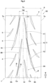
- FIG. 1 is a plan view in which a tread portion 2 of a front wheel tire S 1 of a motorcycle tire set (hereinafter, simply referred to as "tire set") S according to the present embodiment is developed in a flat surface.
- FIG. 2 is a plan view in which a tread portion 2 of a rear wheel tire S2 of the tire set S according to the present embodiment is developed in a flat surface.
- the tire set S is composed of the front wheel tire S1 and the rear wheel tire S2.
- each of the tires S1 and S2 is sometimes referred to as tire 1.
- the "standardized state” is a state where the tire 1 is fitted on a standardized rim (not shown) and inflated to a standardized internal pressure and no load is applied to the tire 1.
- the "standardized rim” is a rim that is defined, in a standard system including a standard on which the tire 1 is based, by the standard for each tire, and is, for example, the "standard rim” in the JATMA standard, the "Design Rim” in the TRA standard, or the “Measuring Rim” in the ETRTO standard.
- the "standardized internal pressure” is an air pressure that is defined, in a standard system including a standard on which the tire 1 is based, by the standard for each tire, and is the “maximum air pressure” in the JATMA standard, the maximum value indicated in the table "TIRE LOAD LIMITS AT VARIOUS COLD INFLATION PRESSURES" in the TRA standard, or the “INFLATION PRESSURE” in the ETRTO standard.
- each of the front wheel tire S1 and the rear wheel tire S2 includes a tread portion 2 having a designated tire rotation direction R.
- the tread portions 2 of the front wheel tire S1 and the rear wheel tire S2 come into contact with the ground from the upper side toward the lower side in the respective drawings based on the tire rotation direction R.
- Each of the tread portions 2 of the front wheel tire S1 and the rear wheel tire S2 has a plurality of inclined grooves 3 provided so as to be inclined with respect to the tire circumferential direction.
- Each of the plurality of inclined grooves 3 includes a first portion 11 extending in a crown region Cr, a second portion 12 extending in a shoulder region Sh, and a third portion 13 connecting the first portion 11 and the second portion 12.
- the third portion 13 has a smaller groove width Wc (shown in FIG. 3(B) ) than the first portion 11 and the second portion 12. Such a third portion 13 suppresses a decrease in the stiffness of a middle portion 3c in the longitudinal direction of the inclined groove 3 in which relatively large deformation is likely to occur. The third portion 13 also suppresses slipping of the first portion 11 and the second portion 12 mainly in the tire circumferential direction during contact with the ground. Accordingly, occurrence of uneven wear is suppressed.
- the first portion 11, the second portion 12, and the third portion 13 are inclined in the same direction with respect to the tire circumferential direction.
- Such an inclined groove 3 reduces a change in tread stiffness to suppress occurrence of uneven wear and suppress deterioration of appearance due to uneven wear.
- FIG. 3(A) is an enlarged view of a third portion 13 in FIG. 1 , and is a plan view of a third portion 13 of the front wheel tire S1.
- FIG. 3(B) is a cross-sectional view taken along a line A-A in FIG. 1 .
- FIG. 4(A) is an enlarged view of a third portion 13 in FIG. 2 , and is a plan view of a third portion 13 of the rear wheel tire S2.
- FIG. 4(B) is a cross-sectional view taken along a line B-B in FIG. 2 .
- each third portion 13 includes a pair of groove edges 20.
- the pair of groove edges 20 include a first groove edge 20e located on the leading edge side in the tire rotation direction R, and a second groove edge 20i located on the trailing edge side in the tire rotation direction R.
- the first groove edge 20e of the present embodiment is located on the outer side in the tire axial direction with respect to the second groove edge 20i.
- the front wheel tire S1 is mainly affected by a braking force, so that wear is likely to occur at each groove edge on the trailing edge side in the tire rotation direction R.
- the rear wheel tire S2 is mainly affected by a driving force, so that wear is likely to occur at each groove edge on the leading edge side in the tire rotation direction R.
- the first groove edge 20e of the front wheel tire S1 is provided with a chamfered portion 10.
- the second groove edge 20i on the trailing edge side of the rear wheel tire S2 is provided with a chamfered portion 10.
- the tire set S according to the present invention makes uneven wear less noticeable and can have improved appearance.
- each groove edge 20e or 20i is specified by the point of intersection of a first virtual line v1 and a second virtual line v2.
- the first virtual line v1 is a line obtained by smoothly extending a groove wall 13a of the third portion 13 to the outer side in the tire radial direction.
- the second virtual line v2 is a line obtained by smoothly extending a tread surface 2a to the groove width center line side.
- the groove width Wc of the third portion 13 is the shortest distance between the first groove edge 20e and the second groove edge 20i.
- a width Wd of the chamfered portion 10 is preferably not less than 40% and further preferably not less than 45% of the groove width Wc of the third portion 13, and is preferably not greater than 90% and further preferably not greater than 85% of the groove width Wc of the third portion 13.
- a length Dd in the tire radial direction of the chamfered portion 10 is preferably not less than 10% and further preferably not less than 15% of a groove depth Dc (shown in FIG. 7 ) of the third portion 13, and is preferably not greater than 35% and further preferably not greater than 30% of the groove depth Dc of the third portion 13.
- the crown region Cr is a region that comes into contact with a flat surface when the tire 1 in the standardized state is brought into contact with the flat surface with the standardized load at a camber angle of 0 degrees.
- the length in the tire axial direction between both ends Ce in the tire axial direction of the crown region Cr is defined as a tread ground-contact width TW.
- each shoulder region Sh is a region between the crown region Cr and a tread end Te.
- Each shoulder region Sh is a region that comes into contact with the ground when a camber angle is given to the tire 1.
- the tread ends Te correspond to both ends in the tire axial direction of the tread portion 2, and are, for example, ends that can come into contact with the ground during cornering around a maximum camber angle.
- the distance in the tire axial direction between the tread ends Te when the tread portion 2 is developed in a flat surface is defined as a tread development width Tx.
- a tire equator C is the midpoint between the tread ends Te.
- the "standardized load” is a load that is defined, in a standard system including a standard on which the tire 1 is based, by the standard for each tire, and is the "maximum load capacity" in the JATMA standard, the maximum value indicated in the table "TIRE LOAD LIMITS AT VARIOUS COLD INFLATION PRESSURES" in the TRA standard, or the "LOAD CAPACITY" in the ETRTO standard.
- the inclined grooves 3 include, for example, first inclined grooves 3A arranged between the tire equator C and one tread end (right side in the drawing) Te, and second inclined grooves 3B arranged between the tire equator C and the other tread end Te.
- first inclined grooves 3A and the second inclined grooves 3B are alternately arranged in the tire circumferential direction.
- the first inclined grooves 3A and the second inclined grooves 3B have a line symmetrical shape with respect to the tire equator C, for example.
- Each inclined groove 3 extends without crossing the tire equator C.
- Such an inclined groove 3 serves to suppress a decrease in the tread stiffness on the tire equator C to which a large ground-contact pressure is applied, and to suppress occurrence of uneven wear.
- a shortest distance Lm (shown in FIG. 1 ) between the inclined groove 3 and the tire equator C is preferably not greater than 10% and further preferably not greater than 8% of the tread ground-contact width TW.
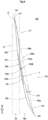
- FIG. 5 is a plan view of an inclined groove 3 of the rear wheel tire S2.
- the third portion 13 in the rear wheel tire S2 and the front wheel tire S1, the third portion 13 includes an inner end 13i connected to the first portion 11 and an outer end 13e connected to the second portion 12.
- the third portion 13 includes a first tapered portion 13A having a groove width that decreases from the inner end 13i toward the second portion 12, and an equal width portion 13B extending with a constant groove width.
- the third portion 13 also includes a second tapered portion 13C having a groove width that decreases from the outer end 13e toward the first portion 11.
- the equal width portion 13B includes not only a mode in which the groove width is uniform along the longitudinal direction but also a mode in which the difference between the maximum groove width and the minimum groove width is not greater than 2 mm.
- the difference between the maximum groove width and the minimum groove width of the equal width portion 13B is preferably not greater than 1 mm.
- the inner end 13i and the outer end 13e are ends located on the second groove edge 20i.
- a shortest distance Ls along a tread surface 2a between the inner end 13i and the tire equator C is preferably not less than 30% and further preferably not less than 35% of the tread ground-contact width TW (shown in FIG. 1 ), and is preferably not greater than 55% and further preferably not greater than 50% of the tread ground-contact width TW (shown in FIG. 1 ). Since the shortest distance Ls is not less than 30% of the tread ground-contact width TW, the first portion 11 can be positioned on the tire equator C side on which it is difficult to drain water, and drainage performance can be maintained at a high level.
- the inner end 13i can be located away from the outer side of the ground-contact width where slipping is likely to occur due to the difference in tread outer diameter, so that occurrence of uneven wear can be suppressed.
- a length Lt in the tire axial direction of the third portion 13 is preferably not less than 5% of the tread development width Tx (shown in FIG. 1 ). Such a third portion 13 keeps the tread stiffness of the shoulder region Sh at a high level and exhibits excellent uneven wear resistance.
- the length Lt of the third portion 13 is further preferably not less than 10% of the tread development width Tx, and is preferably not greater than 23% and further preferably not greater than 20% of the tread development width Tx.
- the third portion 13 is preferably not greater than 55% and further preferably not greater than 45% of the first portion 11 and the second portion 12. Since the groove width Wc of the third portion 13 is not greater than 55% of a groove width Wa of the first portion 11 and a groove width Wb of the second portion 12, the tread stiffness can be increased. If, as for the groove width, the third portion 13 is excessively smaller than the first portion 11 and the second portion 12, drainage performance may deteriorate. Therefore, the groove width Wc of the third portion 13 is preferably not less than 15% and further preferably not less than 20% of the groove width Wa of the first portion 11 and the groove width Wb of the second portion 12. The groove width Wc of the third portion 13 is preferably, for example, 1.2 to 3.5 mm.
- the groove width Wa of the first portion 11, the groove width Wb of the second portion 12, and the groove width Wc of the third portion 13 are each a groove width at the midpoint in the longitudinal direction.
- a groove volume V3 per unit area (not shown) on the tread surface 2a of the third portion 13 is preferably not less than 70% and further preferably not less than 75% of a groove volume V1 per unit area on the tread surface 2a of the first portion 11 and a groove volume V2 per unit area on the tread surface 2a of the second portion 12. Accordingly, smooth passage of water between the first portion 11 and the second portion 12 is maintained.
- the groove volume V3 of the third portion 13 is preferably not greater than 120% and further preferably not greater than 115% of the groove volume V1 of the first portion 11 and the groove volume V2 of the second portion 12.
- Each groove volume (V1, V2 and V3) per unit area is a value obtained by dividing the groove volume of each portion by the area (surface area) of each portion on the tread surface 2a.
- FIG. 6 is a plan view (tread plan view) of the inclined groove 3 of the rear wheel tire S2.
- the first groove edge 20e includes a first equal width edge portion 21e forming the equal width portion 13B.
- the second groove edge 20i includes a second equal width edge portion 21i forming the equal width portion 13B.
- the first portion 11 includes a first leading groove edge 18e located on the leading edge side in the tire rotation direction R, and a first trailing groove edge 18i located on the trailing edge side in the tire rotation direction R with respect to the first leading groove edge 18e.
- the second portion 12 includes a second leading groove edge 19e located on the leading edge side in the tire rotation direction R, and a second trailing groove edge 19i located on the trailing edge side in the tire rotation direction R with respect to the second leading groove edge 19e.
- the chamfered portion 10 includes an outer edge 10a on the tread surface 2a side.
- the outer edge 10a is smoothly connected to the first trailing groove edge 18i.
- the outer edge 10a is smoothly connected to the second trailing groove edge 19i, for example.
- the outer edge 10a of the chamfered portion 10 is smoothly connected to the first leading groove edge 18e and the second leading groove edge 19e.
- the third portion 13 extends in a straight manner in the present embodiment.
- Such a third portion 13 has low drainage resistance and serves to maintain drainage performance at a high level.
- the "straight manner" includes not only a mode in which the first equal width edge portion 21e and the second equal width edge portion 21i are formed only by straight lines, but also a mode in which, for example, the edge portions 21e and 21i are each formed by an arc having a radius of curvature r exceeding 200 mm.
- the third portion 13 may, for example, extend in a curved manner in which the edge portions 21e and 21i are each formed by an arc having a radius of curvature r of 20 to 200 mm.
- the third portion 13 extends in the crown region Cr and the shoulder region Sh.
- a midpoint 13s of the third portion 13 is located in the shoulder region Sh.
- the shoulder region Sh is a region that has a smaller tire circumferential length than the crown region Cr and in which slipping is likely to occur. Therefore, slipping in the shoulder region Sh is suppressed, and the difference in the amount of wear between the shoulder region Sh and the crown region Cr becomes smaller, so that occurrence of uneven wear is suppressed.
- An angle ⁇ 1 of the inclined groove 3 with respect to the tire circumferential direction is preferably not less than 5 degrees and further preferably not less than 7 degrees, and is preferably not greater than 15 degrees and further preferably not greater than 13 degrees.
- the angle ⁇ 1 of the inclined groove 3 is specified by a virtual line va connecting both ends e1 and e2 in the tire circumferential direction of the inclined groove 3.
- FIG. 7 is a cross-sectional view taken along a line D-D in FIG. 2 .
- the third portion 13 is preferably not less than 70% and further preferably not less than 75% of the first portion 11 and the second portion 12, and is preferably not greater than 120% and further preferably not greater than 115% of the first portion 11 and the second portion 12. Since the groove depth Dc of the third portion 13 is not less than 70% and not greater than 120% of a groove depth Da of the first portion 11 and a groove depth Db of the second portion 12, a change in the stiffness in the vicinity of the first portion 11, the second portion 12, and the third portion 13 can be reduced. Therefore, occurrence of uneven wear is suppressed, and appearance is improved.
- the groove depth Da of the first portion 11 and the groove depth Db of the second portion 12 are preferably, for example, 3.5 to 9.5 mm. Such a groove depth of the inclined groove 3 is applied to each of the front wheel tire S1 and the rear wheel tire S2.
- each of the tread portions 2 of the front wheel tire S1 and the rear wheel tire S2 is provided with first sub-inclined grooves 4 and second sub-inclined grooves 5 in the present embodiment.
- the first sub-inclined grooves 4 are, for example, located on the outer side in the tire axial direction with respect to the inclined grooves 3.
- the second sub-inclined grooves 5 are, for example, located on the outer side in the tire axial direction with respect to the first sub-inclined grooves 4.
- Each of the first sub-inclined grooves 4 and the second sub-inclined grooves 5 is not provided with a chamfered portion 10.
- FIG. 8 is a plan view of a tread portion 2 of a front wheel tire S1 according to another embodiment.
- FIG. 9 is a plan view of a tread portion 2 of a rear wheel tire S2 according to the other embodiment.
- each of the first groove edge 20e and the second groove edge 20i of the front wheel tire S1 is provided with a chamfered portion 10.
- each of the first groove edge 20e and the second groove edge 20i of the rear wheel tire S2 is provided with a chamfered portion 10. In such an embodiment as well, appearance can be improved.
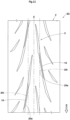
- FIG. 10 is a plan view of a tread portion 2 of a front wheel tire S1 according to still another embodiment.
- the first groove edge 20e is provided with a chamfered portion 10.
- the second groove edge 20i is not provided with a chamfered portion 10.
- the second groove edge 20i may be provided with a chamfered portion 10 (not shown).
- FIG. 11 is a plan view of a tread portion 2 of a rear wheel tire S2 according to still another embodiment.
- the second groove edge 20i is provided with a chamfered portion 10.
- the first groove edge 20e is not provided with a chamfered portion 10.
- the first groove edge 20e may be provided with a chamfered portion 10 (not shown).
- test motorcycle tire set was mounted on a motorcycle.
- a test rider rode the motorcycle on a dry asphalt circuit course. After the ride, the test rider made sensory evaluation for unnoticeability of wear in the vicinity of the third portions of the inclined grooves of the rear wheel tire.
- the test results are indicated as scores with the unnoticeability of wear of Comparative Example 1 being regarded as 100. The higher the value is, the better the appearance is.
- the present invention includes the following aspects.
- a motorcycle tire set including a front wheel tire and a rear wheel tire, wherein
- a groove volume per unit area on the tread surface of the third portion is not less than 70% of a groove volume per unit area on the tread surface of the first portion and a groove volume per unit area on the tread surface of the second portion.
Landscapes
- Engineering & Computer Science (AREA)
- Mechanical Engineering (AREA)
- Tires In General (AREA)
Abstract
Description
- The present invention relates to a motorcycle tire set.
-
Japanese Laid-Open Patent Publication No. 2020-142587 - In general, due to a driving force or a braking force by running, wear is likely to occur at one of a pair of groove edges of the inclined groove. In particular, the groove edges of a groove having a small groove width have a problem that this wear is easily noticeable.
- The present invention has been made in view of the above circumstances, and a main object of the present invention is to provide a motorcycle tire set that can have improved appearance by making wear less noticeable.
- The present invention is directed to a motorcycle tire set including a front wheel tire and a rear wheel tire, wherein: each of the front wheel tire and the rear wheel tire includes a tread portion having a designated tire rotation direction; each of the tread portions of the front wheel tire and the rear wheel tire has a plurality of inclined grooves provided so as to be inclined with respect to a tire circumferential direction; each of the plurality of inclined grooves includes a first portion extending in a crown region, a second portion extending in a shoulder region, and a third portion connecting the first portion and the second portion; the third portion has a smaller groove width than the first portion and the second portion; the first portion, the second portion, and the third portion are inclined in the same direction with respect to the tire circumferential direction; the third portion includes a pair of groove edges; the pair of groove edges include a first groove edge located on a leading edge side in the tire rotation direction, and a second groove edge located on a trailing edge side in the tire rotation direction; the first groove edge of the front wheel tire is provided with a chamfered portion; and the second groove edge of the rear wheel tire is provided with a chamfered portion.
- As a result of adopting the above configuration, the motorcycle tire set according to the present invention can have improved appearance by making wear less noticeable.
-
-
FIG. 1 is a plan view of a tread portion of a front wheel tire according to one embodiment of the present invention; -
FIG. 2 is a plan view of a tread portion of a rear wheel tire according to the one embodiment of the present invention; -
FIG. 3(A) is an enlarged view of a third portion inFIG. 1 ; -
FIG. 3(B) is a cross-sectional view taken along a line A-A inFIG. 1 ; -
FIG. 4(A) is an enlarged view of a third portion inFIG. 2 ; -
FIG. 4(B) is a cross-sectional view taken along a line B-B inFIG. 2 ; -
FIG. 5 is a plan view of an inclined groove of the rear wheel tire; -
FIG. 6 is a plan view of the inclined groove of the rear wheel tire; -
FIG. 7 is a cross-sectional view taken along a line D-D inFIG. 2 ; -
FIG. 8 is a plan view of a tread portion of a front wheel tire according to another embodiment; -
FIG. 9 is a plan view of a tread portion of a rear wheel tire according to the other embodiment; -
FIG. 10 is a plan view of a tread portion of a front wheel tire according to still another embodiment; and -
FIG. 11 is a plan view of a tread portion of a rear wheel tire according to still another embodiment. - Hereinafter, one embodiment of the present invention will be described with reference to the drawings. The drawings contain exaggerated expressions and expressions that differ from the dimensional ratio of the actual structure in order to help the understanding of the present invention. In addition, when there are a plurality of embodiments, the same or common elements are denoted by the same reference characters throughout the description, and the redundant description thereof is omitted.
-
FIG. 1 is a plan view in which atread portion 2 of a frontwheel tire S 1 of a motorcycle tire set (hereinafter, simply referred to as "tire set") S according to the present embodiment is developed in a flat surface.FIG. 2 is a plan view in which atread portion 2 of a rear wheel tire S2 of the tire set S according to the present embodiment is developed in a flat surface. The tire set S is composed of the front wheel tire S1 and the rear wheel tire S2. In the present specification, each of the tires S1 and S2 is sometimes referred to astire 1. - In the present specification, unless otherwise specified, dimensions and the like of components of the
tire 1 are values measured in a standardized state. The "standardized state" is a state where thetire 1 is fitted on a standardized rim (not shown) and inflated to a standardized internal pressure and no load is applied to thetire 1. - The "standardized rim" is a rim that is defined, in a standard system including a standard on which the
tire 1 is based, by the standard for each tire, and is, for example, the "standard rim" in the JATMA standard, the "Design Rim" in the TRA standard, or the "Measuring Rim" in the ETRTO standard. - The "standardized internal pressure" is an air pressure that is defined, in a standard system including a standard on which the
tire 1 is based, by the standard for each tire, and is the "maximum air pressure" in the JATMA standard, the maximum value indicated in the table "TIRE LOAD LIMITS AT VARIOUS COLD INFLATION PRESSURES" in the TRA standard, or the "INFLATION PRESSURE" in the ETRTO standard. - As shown in
FIG. 1 andFIG. 2 , each of the front wheel tire S1 and the rear wheel tire S2 includes atread portion 2 having a designated tire rotation direction R. In the present embodiment, thetread portions 2 of the front wheel tire S1 and the rear wheel tire S2 come into contact with the ground from the upper side toward the lower side in the respective drawings based on the tire rotation direction R. - Each of the
tread portions 2 of the front wheel tire S1 and the rear wheel tire S2 has a plurality ofinclined grooves 3 provided so as to be inclined with respect to the tire circumferential direction. Each of the plurality ofinclined grooves 3 includes afirst portion 11 extending in a crown region Cr, asecond portion 12 extending in a shoulder region Sh, and athird portion 13 connecting thefirst portion 11 and thesecond portion 12. - The
third portion 13 has a smaller groove width Wc (shown inFIG. 3(B) ) than thefirst portion 11 and thesecond portion 12. Such athird portion 13 suppresses a decrease in the stiffness of a middle portion 3c in the longitudinal direction of theinclined groove 3 in which relatively large deformation is likely to occur. Thethird portion 13 also suppresses slipping of thefirst portion 11 and thesecond portion 12 mainly in the tire circumferential direction during contact with the ground. Accordingly, occurrence of uneven wear is suppressed. - The
first portion 11, thesecond portion 12, and thethird portion 13 are inclined in the same direction with respect to the tire circumferential direction. Such aninclined groove 3 reduces a change in tread stiffness to suppress occurrence of uneven wear and suppress deterioration of appearance due to uneven wear. -
FIG. 3(A) is an enlarged view of athird portion 13 inFIG. 1 , and is a plan view of athird portion 13 of the front wheel tire S1.FIG. 3(B) is a cross-sectional view taken along a line A-A inFIG. 1 .FIG. 4(A) is an enlarged view of athird portion 13 inFIG. 2 , and is a plan view of athird portion 13 of the rear wheel tire S2.FIG. 4(B) is a cross-sectional view taken along a line B-B inFIG. 2 . As shown inFIG. 3 andFIG. 4 , eachthird portion 13 includes a pair ofgroove edges 20. The pair ofgroove edges 20 include afirst groove edge 20e located on the leading edge side in the tire rotation direction R, and asecond groove edge 20i located on the trailing edge side in the tire rotation direction R. Thefirst groove edge 20e of the present embodiment is located on the outer side in the tire axial direction with respect to thesecond groove edge 20i. - In the tire set S, the front wheel tire S1 is mainly affected by a braking force, so that wear is likely to occur at each groove edge on the trailing edge side in the tire rotation direction R. In addition, the rear wheel tire S2 is mainly affected by a driving force, so that wear is likely to occur at each groove edge on the leading edge side in the tire rotation direction R. In the present invention, the
first groove edge 20e of the front wheel tire S1 is provided with a chamferedportion 10. In addition, thesecond groove edge 20i on the trailing edge side of the rear wheel tire S2 is provided with a chamferedportion 10. Accordingly, even when more wear occurs at thesecond groove edge 20i in the front wheel tire S1, the appearance of thefirst groove edge 20e which is provided with the chamferedportion 10 and the appearance of thesecond groove edge 20i at which the wear has occurred become similar to each other, so that the uneven wear of thethird portion 13 is made less noticeable in appearance. Even when more wear occurs at thefirst groove edge 20e in the rear wheel tire S2, the appearance of thesecond groove edge 20i which is provided with the chamferedportion 10 and the appearance of thefirst groove edge 20e at which the wear has occurred become similar to each other, so that the uneven wear of thethird portion 13 is made less noticeable in appearance. Therefore, the tire set S according to the present invention makes uneven wear less noticeable and can have improved appearance. - In the case where the
first groove edge 20e or thesecond groove edge 20i is provided with achamfered portion 10, eachgroove edge groove wall 13a of thethird portion 13 to the outer side in the tire radial direction. The second virtual line v2 is a line obtained by smoothly extending atread surface 2a to the groove width center line side. The groove width Wc of thethird portion 13 is the shortest distance between thefirst groove edge 20e and thesecond groove edge 20i. - In the front wheel tire S1 and the rear wheel tire S2, a width Wd of the chamfered
portion 10 is preferably not less than 40% and further preferably not less than 45% of the groove width Wc of thethird portion 13, and is preferably not greater than 90% and further preferably not greater than 85% of the groove width Wc of thethird portion 13. A length Dd in the tire radial direction of the chamferedportion 10 is preferably not less than 10% and further preferably not less than 15% of a groove depth Dc (shown inFIG. 7 ) of thethird portion 13, and is preferably not greater than 35% and further preferably not greater than 30% of the groove depth Dc of thethird portion 13. - As shown in
FIG. 1 andFIG. 2 , in the present specification, the crown region Cr is a region that comes into contact with a flat surface when thetire 1 in the standardized state is brought into contact with the flat surface with the standardized load at a camber angle of 0 degrees. The length in the tire axial direction between both ends Ce in the tire axial direction of the crown region Cr is defined as a tread ground-contact width TW. In addition, each shoulder region Sh is a region between the crown region Cr and a tread end Te. Each shoulder region Sh is a region that comes into contact with the ground when a camber angle is given to thetire 1. - The tread ends Te correspond to both ends in the tire axial direction of the
tread portion 2, and are, for example, ends that can come into contact with the ground during cornering around a maximum camber angle. In the present specification, the distance in the tire axial direction between the tread ends Te when thetread portion 2 is developed in a flat surface is defined as a tread development width Tx. A tire equator C is the midpoint between the tread ends Te. - The "standardized load" is a load that is defined, in a standard system including a standard on which the
tire 1 is based, by the standard for each tire, and is the "maximum load capacity" in the JATMA standard, the maximum value indicated in the table "TIRE LOAD LIMITS AT VARIOUS COLD INFLATION PRESSURES" in the TRA standard, or the "LOAD CAPACITY" in the ETRTO standard. - In the
tire 1, theinclined grooves 3 include, for example, first inclinedgrooves 3A arranged between the tire equator C and one tread end (right side in the drawing) Te, and secondinclined grooves 3B arranged between the tire equator C and the other tread end Te. In the present embodiment, the firstinclined grooves 3A and the secondinclined grooves 3B are alternately arranged in the tire circumferential direction. The firstinclined grooves 3A and the secondinclined grooves 3B have a line symmetrical shape with respect to the tire equator C, for example. - Each
inclined groove 3 extends without crossing the tire equator C. Such aninclined groove 3 serves to suppress a decrease in the tread stiffness on the tire equator C to which a large ground-contact pressure is applied, and to suppress occurrence of uneven wear. In order to suppress occurrence of uneven wear and maintain the basic performance of thetire 1, a shortest distance Lm (shown inFIG. 1 ) between theinclined groove 3 and the tire equator C is preferably not greater than 10% and further preferably not greater than 8% of the tread ground-contact width TW. -
FIG. 5 is a plan view of aninclined groove 3 of the rear wheel tire S2. As represented inFIG. 5 , in the rear wheel tire S2 and the front wheel tire S1, thethird portion 13 includes aninner end 13i connected to thefirst portion 11 and anouter end 13e connected to thesecond portion 12. In addition, thethird portion 13 includes a firsttapered portion 13A having a groove width that decreases from theinner end 13i toward thesecond portion 12, and anequal width portion 13B extending with a constant groove width. In the present embodiment, thethird portion 13 also includes a secondtapered portion 13C having a groove width that decreases from theouter end 13e toward thefirst portion 11. Theequal width portion 13B includes not only a mode in which the groove width is uniform along the longitudinal direction but also a mode in which the difference between the maximum groove width and the minimum groove width is not greater than 2 mm. The difference between the maximum groove width and the minimum groove width of theequal width portion 13B is preferably not greater than 1 mm. In addition, in the present embodiment, theinner end 13i and theouter end 13e are ends located on thesecond groove edge 20i. - A shortest distance Ls along a
tread surface 2a between theinner end 13i and the tire equator C is preferably not less than 30% and further preferably not less than 35% of the tread ground-contact width TW (shown inFIG. 1 ), and is preferably not greater than 55% and further preferably not greater than 50% of the tread ground-contact width TW (shown inFIG. 1 ). Since the shortest distance Ls is not less than 30% of the tread ground-contact width TW, thefirst portion 11 can be positioned on the tire equator C side on which it is difficult to drain water, and drainage performance can be maintained at a high level. Since the shortest distance Ls is not greater than 55% of the tread ground-contact width TW, theinner end 13i can be located away from the outer side of the ground-contact width where slipping is likely to occur due to the difference in tread outer diameter, so that occurrence of uneven wear can be suppressed. - A length Lt in the tire axial direction of the
third portion 13 is preferably not less than 5% of the tread development width Tx (shown inFIG. 1 ). Such athird portion 13 keeps the tread stiffness of the shoulder region Sh at a high level and exhibits excellent uneven wear resistance. In consideration of suppressing a decrease in the basic performance of thetire 1, the length Lt of thethird portion 13 is further preferably not less than 10% of the tread development width Tx, and is preferably not greater than 23% and further preferably not greater than 20% of the tread development width Tx. - As for the groove width, the
third portion 13 is preferably not greater than 55% and further preferably not greater than 45% of thefirst portion 11 and thesecond portion 12. Since the groove width Wc of thethird portion 13 is not greater than 55% of a groove width Wa of thefirst portion 11 and a groove width Wb of thesecond portion 12, the tread stiffness can be increased. If, as for the groove width, thethird portion 13 is excessively smaller than thefirst portion 11 and thesecond portion 12, drainage performance may deteriorate. Therefore, the groove width Wc of thethird portion 13 is preferably not less than 15% and further preferably not less than 20% of the groove width Wa of thefirst portion 11 and the groove width Wb of thesecond portion 12. The groove width Wc of thethird portion 13 is preferably, for example, 1.2 to 3.5 mm. The groove width Wa of thefirst portion 11, the groove width Wb of thesecond portion 12, and the groove width Wc of thethird portion 13 are each a groove width at the midpoint in the longitudinal direction. - A groove volume V3 per unit area (not shown) on the
tread surface 2a of thethird portion 13 is preferably not less than 70% and further preferably not less than 75% of a groove volume V1 per unit area on thetread surface 2a of thefirst portion 11 and a groove volume V2 per unit area on thetread surface 2a of thesecond portion 12. Accordingly, smooth passage of water between thefirst portion 11 and thesecond portion 12 is maintained. In consideration of the viewpoint of maintaining the stiffness in the vicinity of thethird portion 13 at a high level, the groove volume V3 of thethird portion 13 is preferably not greater than 120% and further preferably not greater than 115% of the groove volume V1 of thefirst portion 11 and the groove volume V2 of thesecond portion 12. Each groove volume (V1, V2 and V3) per unit area is a value obtained by dividing the groove volume of each portion by the area (surface area) of each portion on thetread surface 2a. -
FIG. 6 is a plan view (tread plan view) of theinclined groove 3 of the rear wheel tire S2. As represented inFIG. 6 , in the front wheel tire S1 and the rear wheel tire S2, thefirst groove edge 20e includes a first equalwidth edge portion 21e forming theequal width portion 13B. In addition, thesecond groove edge 20i includes a second equalwidth edge portion 21i forming theequal width portion 13B. Furthermore, thefirst portion 11 includes a firstleading groove edge 18e located on the leading edge side in the tire rotation direction R, and a first trailinggroove edge 18i located on the trailing edge side in the tire rotation direction R with respect to the first leadinggroove edge 18e. In addition, thesecond portion 12 includes a secondleading groove edge 19e located on the leading edge side in the tire rotation direction R, and a second trailinggroove edge 19i located on the trailing edge side in the tire rotation direction R with respect to the second leadinggroove edge 19e. - The chamfered
portion 10 includes anouter edge 10a on thetread surface 2a side. In the present embodiment, theouter edge 10a is smoothly connected to the first trailinggroove edge 18i. In addition, theouter edge 10a is smoothly connected to the second trailinggroove edge 19i, for example. As shown inFIG. 1 , in the front wheel tire S1, theouter edge 10a of the chamferedportion 10 is smoothly connected to the first leadinggroove edge 18e and the second leadinggroove edge 19e. - As shown in
FIG. 6 , in the front wheel tire S1 and the rear wheel tire S2, thethird portion 13 extends in a straight manner in the present embodiment. Such athird portion 13 has low drainage resistance and serves to maintain drainage performance at a high level. In the present specification, the "straight manner" includes not only a mode in which the first equalwidth edge portion 21e and the second equalwidth edge portion 21i are formed only by straight lines, but also a mode in which, for example, theedge portions third portion 13 may, for example, extend in a curved manner in which theedge portions - In the present embodiment, the
third portion 13 extends in the crown region Cr and the shoulder region Sh. Amidpoint 13s of thethird portion 13 is located in the shoulder region Sh. The shoulder region Sh is a region that has a smaller tire circumferential length than the crown region Cr and in which slipping is likely to occur. Therefore, slipping in the shoulder region Sh is suppressed, and the difference in the amount of wear between the shoulder region Sh and the crown region Cr becomes smaller, so that occurrence of uneven wear is suppressed. - An angle θ1 of the
inclined groove 3 with respect to the tire circumferential direction is preferably not less than 5 degrees and further preferably not less than 7 degrees, and is preferably not greater than 15 degrees and further preferably not greater than 13 degrees. The angle θ1 of theinclined groove 3 is specified by a virtual line va connecting both ends e1 and e2 in the tire circumferential direction of theinclined groove 3. -
FIG. 7 is a cross-sectional view taken along a line D-D inFIG. 2 . As shown inFIG. 7 , as for the groove depth, thethird portion 13 is preferably not less than 70% and further preferably not less than 75% of thefirst portion 11 and thesecond portion 12, and is preferably not greater than 120% and further preferably not greater than 115% of thefirst portion 11 and thesecond portion 12. Since the groove depth Dc of thethird portion 13 is not less than 70% and not greater than 120% of a groove depth Da of thefirst portion 11 and a groove depth Db of thesecond portion 12, a change in the stiffness in the vicinity of thefirst portion 11, thesecond portion 12, and thethird portion 13 can be reduced. Therefore, occurrence of uneven wear is suppressed, and appearance is improved. The groove depth Da of thefirst portion 11 and the groove depth Db of thesecond portion 12 are preferably, for example, 3.5 to 9.5 mm. Such a groove depth of theinclined groove 3 is applied to each of the front wheel tire S1 and the rear wheel tire S2. - As shown in
FIG. 1 andFIG. 2 , each of thetread portions 2 of the front wheel tire S1 and the rear wheel tire S2 is provided with firstsub-inclined grooves 4 and secondsub-inclined grooves 5 in the present embodiment. The firstsub-inclined grooves 4 are, for example, located on the outer side in the tire axial direction with respect to theinclined grooves 3. The secondsub-inclined grooves 5 are, for example, located on the outer side in the tire axial direction with respect to the firstsub-inclined grooves 4. Each of the firstsub-inclined grooves 4 and the secondsub-inclined grooves 5 is not provided with a chamferedportion 10. -
FIG. 8 is a plan view of atread portion 2 of a front wheel tire S1 according to another embodiment.FIG. 9 is a plan view of atread portion 2 of a rear wheel tire S2 according to the other embodiment. As shown inFIG. 8 , in this embodiment, each of thefirst groove edge 20e and thesecond groove edge 20i of the front wheel tire S1 is provided with a chamferedportion 10. As shown inFIG. 9 , in this embodiment, each of thefirst groove edge 20e and thesecond groove edge 20i of the rear wheel tire S2 is provided with a chamferedportion 10. In such an embodiment as well, appearance can be improved. -
FIG. 10 is a plan view of atread portion 2 of a front wheel tire S1 according to still another embodiment. In this embodiment as well, in the front wheel tire S1, thefirst groove edge 20e is provided with a chamferedportion 10. In this embodiment, thesecond groove edge 20i is not provided with a chamferedportion 10. Thesecond groove edge 20i may be provided with a chamfered portion 10 (not shown). -
FIG. 11 is a plan view of atread portion 2 of a rear wheel tire S2 according to still another embodiment. In this embodiment as well, in the rear wheel tire S2, thesecond groove edge 20i is provided with a chamferedportion 10. In addition, in this embodiment, thefirst groove edge 20e is not provided with a chamferedportion 10. Thefirst groove edge 20e may be provided with a chamfered portion 10 (not shown). - Although the motorcycle tire set according to the embodiments of the present invention has been described in detail above, the present invention is not limited to the above specific embodiments, and various modifications can be made to implement the present invention.
- Motorcycle tire sets having the basic pattern in
FIG. 1 orFIG. 2 were produced as test motorcycle tire sets, and were tested for appearance. The common specifications and the test method for the respective test tires are as follows. - Each test motorcycle tire set was mounted on a motorcycle. A test rider rode the motorcycle on a dry asphalt circuit course. After the ride, the test rider made sensory evaluation for unnoticeability of wear in the vicinity of the third portions of the inclined grooves of the rear wheel tire. The test results are indicated as scores with the unnoticeability of wear of Comparative Example 1 being regarded as 100. The higher the value is, the better the appearance is.
- Tire size: 120/70ZR17 (front wheel), 200/55ZR17 (rear wheel)
- Rim size: MT3.50×17 (front wheel), MT6.00x 17 (rear wheel)
- Internal pressure: 250 kPa (front wheel), 290 kPa (rear wheel)
- Engine displacement: 1000 cc
- Riding distance: 200 km
- Average speed: 120 km/h
- The test results are shown in Table 1.
- As a result of the test, it is confirmed that as for the rear wheel tire, the tire of each Example has improved appearance (initial period of wear) as compared to the tire of Comparative Example 1. In addition, the same results were obtained for the front wheel tire.
- The present invention includes the following aspects.
- A motorcycle tire set including a front wheel tire and a rear wheel tire, wherein
- each of the front wheel tire and the rear wheel tire includes a tread portion having a designated tire rotation direction,
- each of the tread portions of the front wheel tire and the rear wheel tire has a plurality of inclined grooves provided so as to be inclined with respect to a tire circumferential direction,
- each of the plurality of inclined grooves includes a first portion extending in a crown region, a second portion extending in a shoulder region, and a third portion connecting the first portion and the second portion,
- the third portion has a smaller groove width than the first portion and the second portion,
- the first portion, the second portion, and the third portion are inclined in the same direction with respect to the tire circumferential direction,
- the third portion includes a pair of groove edges,
- the pair of groove edges include a first groove edge located on a leading edge side in the tire rotation direction, and a second groove edge located on a trailing edge side in the tire rotation direction,
- the first groove edge of the front wheel tire is provided with a chamfered portion, and
- the second groove edge of the rear wheel tire is provided with a chamfered portion.
- The motorcycle tire set according to
Present Invention 1, wherein the second groove edge of the front wheel tire is provided with a chamfered portion. - The motorcycle tire set according to
Present Invention - The motorcycle tire set according to any one of
Present Inventions 1 to 3, wherein - the third portion includes an inner end connected to the first portion, and
- a shortest distance along a tread surface between the inner end and a tire equator is 30% to 55% of a tread ground-contact width.
- The motorcycle tire set according to any one of
Present Inventions 1 to 4, wherein, in a tread plan view in which the tread portion is developed in a flat surface, the third portion extends in a straight manner. - The motorcycle tire set according to any one of
Present Inventions 1 to 4, wherein, in a tread plan view in which the tread portion is developed in a flat surface, the third portion extends in a curved manner. - The motorcycle tire set according to any one of
Present Inventions 1 to 6, wherein, as for a groove depth, the third portion is 70% to 120% of the first portion and the second portion. - The motorcycle tire set according to any one of
Present Inventions 1 to 7, wherein, as for a groove width, the third portion is not greater than 60% of the first portion and the second portion. - The motorcycle tire set according to any one of
Present Inventions 1 to 8, wherein a length in a tire axial direction of the third portion is not less than 5% of a tread development width. - The motorcycle tire set according to any one of
Present Inventions 1 to 9, wherein a groove volume per unit area on the tread surface of the third portion is not less than 70% of a groove volume per unit area on the tread surface of the first portion and a groove volume per unit area on the tread surface of the second portion.
| Comparative Example 1 | Example 1 | Example 2 | |
| Wd (mm) | 1.5 | 1.5 | 1.5 |
| Groove edge provided with chamfered portion | Only first groove edge | Only second groove edge | Pair of groove edges |
| Appearance [Score: higher value is better] | 100 | 110 | 108 |
Claims (10)
- A motorcycle tire set (S) comprising a front wheel tire (S1) and a rear wheel tire (S2), whereineach of the front wheel tire (S1) and the rear wheel tire (S2) includes a tread portion (2) having a designated tire rotation direction (R),each of the tread portions (2) of the front wheel tire (S1) and the rear wheel tire (S2) has a plurality of inclined grooves (3) provided so as to be inclined with respect to a tire circumferential direction,each of the plurality of inclined grooves (3) includes a first portion (11) extending in a crown region (Cr), a second portion (12) extending in a shoulder region (Sh), and a third portion (13) connecting the first portion (11) and the second portion (12),the third portion (13) has a smaller groove width (Wc) than the first portion (11) and the second portion (12),the first portion (11), the second portion (12), and the third portion (13) are inclined in the same direction with respect to the tire circumferential direction,the third portion (13) includes a pair of groove edges (20),the pair of groove edges (20) include a first groove edge (20e) located on a leading edge side in the tire rotation direction (R), and a second groove edge (20i) located on a trailing edge side in the tire rotation direction (R),the first groove edge (20e) of the front wheel tire (S1) is provided with a chamfered portion (10), andthe second groove edge (20i) of the rear wheel tire (S2) is provided with a chamfered portion (10).
- The motorcycle tire set (S) according to claim 1, wherein the second groove edge (20i) of the front wheel tire (S1) is provided with a chamfered portion (10).
- The motorcycle tire set (S) according to claim 1 or 2, wherein the first groove edge (20e) of the rear wheel tire (S2) is provided with a chamfered portion (10).
- The motorcycle tire set (S) according to any one of claims 1 to 3, whereinthe third portion (13) includes an inner end (13i) connected to the first portion (11), anda shortest distance (Ls) along a tread surface (2a) between the inner end (13i) and a tire equator (C) is 30% to 55% of a tread ground-contact width (TW).
- The motorcycle tire set (S) according to any one of claims 1 to 4, wherein, in a tread plan view in which the tread portion (2) is developed in a flat surface, the third portion (13) extends in a straight manner.
- The motorcycle tire set (S) according to any one of claims 1 to 4, wherein, in a tread plan view in which the tread portion (2) is developed in a flat surface, the third portion (13) extends in a curved manner.
- The motorcycle tire set (S) according to any one of claims 1 to 6, wherein, as for a groove depth, the third portion (13) is 70% to 120% of the first portion (11) and the second portion (12).
- The motorcycle tire set (S) according to any one of claims 1 to 7, wherein, as for a groove width, the third portion (13) is not greater than 60% of the first portion (11) and the second portion (12).
- The motorcycle tire set (S) according to any one of claims 1 to 8, wherein a length (Lt) in a tire axial direction of the third portion (13) is not less than 5% of a tread development width (Tx).
- The motorcycle tire set (S) according to any one of claims 1 to 9, wherein a groove volume (V3) per unit area on the tread surface (2a) of the third portion (13) is not less than 70% of a groove volume (V1) per unit area on the tread surface (2a) of the first portion (11) and a groove volume (V2) per unit area on the tread surface (2a) of the second portion (12).
Applications Claiming Priority (1)
| Application Number | Priority Date | Filing Date | Title |
|---|---|---|---|
| JP2023009622A JP2024105072A (en) | 2023-01-25 | 2023-01-25 | Motorcycle tire set |
Publications (2)
| Publication Number | Publication Date |
|---|---|
| EP4406762A1 true EP4406762A1 (en) | 2024-07-31 |
| EP4406762B1 EP4406762B1 (en) | 2025-10-01 |
Family
ID=89661516
Family Applications (1)
| Application Number | Title | Priority Date | Filing Date |
|---|---|---|---|
| EP24152571.6A Active EP4406762B1 (en) | 2023-01-25 | 2024-01-18 | Motorcycle tire set |
Country Status (4)
| Country | Link |
|---|---|
| US (1) | US12434512B2 (en) |
| EP (1) | EP4406762B1 (en) |
| JP (1) | JP2024105072A (en) |
| CN (1) | CN118386735A (en) |
Cited By (1)
| Publication number | Priority date | Publication date | Assignee | Title |
|---|---|---|---|---|
| EP4245573B1 (en) * | 2022-03-15 | 2024-12-11 | Sumitomo Rubber Industries, Ltd. | Motorcycle tire |
Families Citing this family (6)
| Publication number | Priority date | Publication date | Assignee | Title |
|---|---|---|---|---|
| USD1059251S1 (en) * | 2023-06-14 | 2025-01-28 | Compagnie Generale Des Etablissements Michelin | Tire |
| USD1074574S1 (en) * | 2023-08-16 | 2025-05-13 | Sichuan Yuanxing Rubber Co., Ltd. | Tire |
| JP1785504S (en) * | 2023-12-12 | 2024-11-26 | Motorcycle tires | |
| JP1785505S (en) * | 2023-12-12 | 2024-11-26 | Motorcycle tires | |
| JP1798607S (en) * | 2024-10-24 | 2025-05-15 | Motorcycle tires | |
| JP1798606S (en) * | 2024-10-24 | 2025-05-15 | Motorcycle tires |
Citations (3)
| Publication number | Priority date | Publication date | Assignee | Title |
|---|---|---|---|---|
| JP2020142587A (en) | 2019-03-05 | 2020-09-10 | 住友ゴム工業株式会社 | tire |
| EP3705313B1 (en) * | 2019-03-05 | 2021-04-21 | Sumitomo Rubber Industries, Ltd. | Tyre |
| JP2022165795A (en) * | 2021-04-20 | 2022-11-01 | 住友ゴム工業株式会社 | Motorcycle tires and tire sets |
Family Cites Families (5)
| Publication number | Priority date | Publication date | Assignee | Title |
|---|---|---|---|---|
| JP2009012543A (en) * | 2007-07-03 | 2009-01-22 | Sumitomo Rubber Ind Ltd | Motorcycle tires |
| JP4989753B2 (en) * | 2010-06-09 | 2012-08-01 | 住友ゴム工業株式会社 | Motorcycle tires |
| JP7625871B2 (en) * | 2021-01-25 | 2025-02-04 | 住友ゴム工業株式会社 | Motorcycle tires and motorcycle tire pairs |
| JP7711415B2 (en) | 2021-04-09 | 2025-07-23 | 住友ゴム工業株式会社 | Motorcycle tires |
| JP7647266B2 (en) * | 2021-04-09 | 2025-03-18 | 住友ゴム工業株式会社 | Motorcycle tires |
-
2023
- 2023-01-25 JP JP2023009622A patent/JP2024105072A/en active Pending
- 2023-12-18 CN CN202311736837.8A patent/CN118386735A/en active Pending
- 2023-12-28 US US18/398,415 patent/US12434512B2/en active Active
-
2024
- 2024-01-18 EP EP24152571.6A patent/EP4406762B1/en active Active
Patent Citations (4)
| Publication number | Priority date | Publication date | Assignee | Title |
|---|---|---|---|---|
| JP2020142587A (en) | 2019-03-05 | 2020-09-10 | 住友ゴム工業株式会社 | tire |
| US20200282775A1 (en) * | 2019-03-05 | 2020-09-10 | Sumitomo Rubber Industries, Ltd. | Tyre |
| EP3705313B1 (en) * | 2019-03-05 | 2021-04-21 | Sumitomo Rubber Industries, Ltd. | Tyre |
| JP2022165795A (en) * | 2021-04-20 | 2022-11-01 | 住友ゴム工業株式会社 | Motorcycle tires and tire sets |
Cited By (1)
| Publication number | Priority date | Publication date | Assignee | Title |
|---|---|---|---|---|
| EP4245573B1 (en) * | 2022-03-15 | 2024-12-11 | Sumitomo Rubber Industries, Ltd. | Motorcycle tire |
Also Published As
| Publication number | Publication date |
|---|---|
| JP2024105072A (en) | 2024-08-06 |
| CN118386735A (en) | 2024-07-26 |
| US12434512B2 (en) | 2025-10-07 |
| US20240246365A1 (en) | 2024-07-25 |
| EP4406762B1 (en) | 2025-10-01 |
Similar Documents
| Publication | Publication Date | Title |
|---|---|---|
| EP4406762B1 (en) | Motorcycle tire set | |
| EP3705314B1 (en) | Tyre | |
| EP4406761B1 (en) | Motorcycle tire set | |
| EP3178668B1 (en) | Pneumatic tire | |
| EP1437237B1 (en) | Pneumatic tire | |
| EP2594417B1 (en) | Run-flat tire | |
| EP3705313B1 (en) | Tyre | |
| US11267290B2 (en) | Tire | |
| CN114734757B (en) | Pneumatic radial tire | |
| KR20100066357A (en) | Pneumatic tire | |
| EP3456552B1 (en) | Tire | |
| EP4538064A1 (en) | Motorcycle tire | |
| JP5890790B2 (en) | Pneumatic tire | |
| JP7095410B2 (en) | tire | |
| US11904639B2 (en) | Tire | |
| US11618284B2 (en) | Tire | |
| JP7275782B2 (en) | tire | |
| EP3718789B1 (en) | Tire | |
| US20250178379A1 (en) | Two-wheeled vehicle tire for running on rough terrain | |
| JP4285617B2 (en) | Pneumatic radial tire | |
| EP3718787B1 (en) | Tire | |
| US11772429B2 (en) | Tire | |
| EP4566843B1 (en) | Pneumatic tire | |
| US11505006B2 (en) | Tyre | |
| CN116766832A (en) | Tyre for motorcycle |
Legal Events
| Date | Code | Title | Description |
|---|---|---|---|
| PUAI | Public reference made under article 153(3) epc to a published international application that has entered the european phase |
Free format text: ORIGINAL CODE: 0009012 |
|
| STAA | Information on the status of an ep patent application or granted ep patent |
Free format text: STATUS: THE APPLICATION HAS BEEN PUBLISHED |
|
| AK | Designated contracting states |
Kind code of ref document: A1 Designated state(s): AL AT BE BG CH CY CZ DE DK EE ES FI FR GB GR HR HU IE IS IT LI LT LU LV MC ME MK MT NL NO PL PT RO RS SE SI SK SM TR |
|
| STAA | Information on the status of an ep patent application or granted ep patent |
Free format text: STATUS: REQUEST FOR EXAMINATION WAS MADE |
|
| 17P | Request for examination filed |
Effective date: 20240926 |
|
| RBV | Designated contracting states (corrected) |
Designated state(s): AL AT BE BG CH CY CZ DE DK EE ES FI FR GB GR HR HU IE IS IT LI LT LU LV MC ME MK MT NL NO PL PT RO RS SE SI SK SM TR |
|
| P01 | Opt-out of the competence of the unified patent court (upc) registered |
Free format text: CASE NUMBER: APP_12401/2025 Effective date: 20250313 |
|
| GRAP | Despatch of communication of intention to grant a patent |
Free format text: ORIGINAL CODE: EPIDOSNIGR1 |
|
| STAA | Information on the status of an ep patent application or granted ep patent |
Free format text: STATUS: GRANT OF PATENT IS INTENDED |
|
| INTG | Intention to grant announced |
Effective date: 20250625 |
|
| RIN1 | Information on inventor provided before grant (corrected) |
Inventor name: OTANI, MASAFUMI Inventor name: SATO, RYOTA |
|
| GRAS | Grant fee paid |
Free format text: ORIGINAL CODE: EPIDOSNIGR3 |
|
| GRAA | (expected) grant |
Free format text: ORIGINAL CODE: 0009210 |
|
| STAA | Information on the status of an ep patent application or granted ep patent |
Free format text: STATUS: THE PATENT HAS BEEN GRANTED |
|
| AK | Designated contracting states |
Kind code of ref document: B1 Designated state(s): AL AT BE BG CH CY CZ DE DK EE ES FI FR GB GR HR HU IE IS IT LI LT LU LV MC ME MK MT NL NO PL PT RO RS SE SI SK SM TR |
|
| REG | Reference to a national code |
Ref country code: GB Ref legal event code: FG4D Ref country code: CH Ref legal event code: F10 Free format text: ST27 STATUS EVENT CODE: U-0-0-F10-F00 (AS PROVIDED BY THE NATIONAL OFFICE) Effective date: 20251001 |
|
| REG | Reference to a national code |
Ref country code: IE Ref legal event code: FG4D |
|
| REG | Reference to a national code |
Ref country code: DE Ref legal event code: R096 Ref document number: 602024000758 Country of ref document: DE |
|
| REG | Reference to a national code |
Ref country code: NL Ref legal event code: MP Effective date: 20251001 |
|
| REG | Reference to a national code |
Ref country code: AT Ref legal event code: MK05 Ref document number: 1842179 Country of ref document: AT Kind code of ref document: T Effective date: 20251001 |
|
| PG25 | Lapsed in a contracting state [announced via postgrant information from national office to epo] |
Ref country code: NL Free format text: LAPSE BECAUSE OF FAILURE TO SUBMIT A TRANSLATION OF THE DESCRIPTION OR TO PAY THE FEE WITHIN THE PRESCRIBED TIME-LIMIT Effective date: 20251001 |
|
| PG25 | Lapsed in a contracting state [announced via postgrant information from national office to epo] |
Ref country code: ES Free format text: LAPSE BECAUSE OF FAILURE TO SUBMIT A TRANSLATION OF THE DESCRIPTION OR TO PAY THE FEE WITHIN THE PRESCRIBED TIME-LIMIT Effective date: 20251001 |
|
| REG | Reference to a national code |
Ref country code: LT Ref legal event code: MG9D |
|
| PG25 | Lapsed in a contracting state [announced via postgrant information from national office to epo] |
Ref country code: NO Free format text: LAPSE BECAUSE OF FAILURE TO SUBMIT A TRANSLATION OF THE DESCRIPTION OR TO PAY THE FEE WITHIN THE PRESCRIBED TIME-LIMIT Effective date: 20260101 |
|
| PGFP | Annual fee paid to national office [announced via postgrant information from national office to epo] |
Ref country code: DE Payment date: 20260328 Year of fee payment: 3 |
|
| PG25 | Lapsed in a contracting state [announced via postgrant information from national office to epo] |
Ref country code: FI Free format text: LAPSE BECAUSE OF FAILURE TO SUBMIT A TRANSLATION OF THE DESCRIPTION OR TO PAY THE FEE WITHIN THE PRESCRIBED TIME-LIMIT Effective date: 20251001 Ref country code: HR Free format text: LAPSE BECAUSE OF FAILURE TO SUBMIT A TRANSLATION OF THE DESCRIPTION OR TO PAY THE FEE WITHIN THE PRESCRIBED TIME-LIMIT Effective date: 20251001 Ref country code: AT Free format text: LAPSE BECAUSE OF FAILURE TO SUBMIT A TRANSLATION OF THE DESCRIPTION OR TO PAY THE FEE WITHIN THE PRESCRIBED TIME-LIMIT Effective date: 20251001 |
|
| PG25 | Lapsed in a contracting state [announced via postgrant information from national office to epo] |
Ref country code: RS Free format text: LAPSE BECAUSE OF FAILURE TO SUBMIT A TRANSLATION OF THE DESCRIPTION OR TO PAY THE FEE WITHIN THE PRESCRIBED TIME-LIMIT Effective date: 20260101 |
|
| PG25 | Lapsed in a contracting state [announced via postgrant information from national office to epo] |
Ref country code: IS Free format text: LAPSE BECAUSE OF FAILURE TO SUBMIT A TRANSLATION OF THE DESCRIPTION OR TO PAY THE FEE WITHIN THE PRESCRIBED TIME-LIMIT Effective date: 20260201 |
|
| PGFP | Annual fee paid to national office [announced via postgrant information from national office to epo] |
Ref country code: FR Payment date: 20260123 Year of fee payment: 3 |
|
| PG25 | Lapsed in a contracting state [announced via postgrant information from national office to epo] |
Ref country code: CZ Free format text: LAPSE BECAUSE OF FAILURE TO SUBMIT A TRANSLATION OF THE DESCRIPTION OR TO PAY THE FEE WITHIN THE PRESCRIBED TIME-LIMIT Effective date: 20251001 Ref country code: PT Free format text: LAPSE BECAUSE OF FAILURE TO SUBMIT A TRANSLATION OF THE DESCRIPTION OR TO PAY THE FEE WITHIN THE PRESCRIBED TIME-LIMIT Effective date: 20260202 |
|
| PG25 | Lapsed in a contracting state [announced via postgrant information from national office to epo] |
Ref country code: PL Free format text: LAPSE BECAUSE OF FAILURE TO SUBMIT A TRANSLATION OF THE DESCRIPTION OR TO PAY THE FEE WITHIN THE PRESCRIBED TIME-LIMIT Effective date: 20251001 |
|
| PG25 | Lapsed in a contracting state [announced via postgrant information from national office to epo] |
Ref country code: LV Free format text: LAPSE BECAUSE OF FAILURE TO SUBMIT A TRANSLATION OF THE DESCRIPTION OR TO PAY THE FEE WITHIN THE PRESCRIBED TIME-LIMIT Effective date: 20251001 |
|
| PG25 | Lapsed in a contracting state [announced via postgrant information from national office to epo] |
Ref country code: BG Free format text: LAPSE BECAUSE OF FAILURE TO SUBMIT A TRANSLATION OF THE DESCRIPTION OR TO PAY THE FEE WITHIN THE PRESCRIBED TIME-LIMIT Effective date: 20251001 |