EP4406759A1 - Tire - Google Patents
Tire Download PDFInfo
- Publication number
- EP4406759A1 EP4406759A1 EP22872480.3A EP22872480A EP4406759A1 EP 4406759 A1 EP4406759 A1 EP 4406759A1 EP 22872480 A EP22872480 A EP 22872480A EP 4406759 A1 EP4406759 A1 EP 4406759A1
- Authority
- EP
- European Patent Office
- Prior art keywords
- tire
- groove
- shoulder
- width direction
- tread surface
- Prior art date
- Legal status (The legal status is an assumption and is not a legal conclusion. Google has not performed a legal analysis and makes no representation as to the accuracy of the status listed.)
- Granted
Links
Images



Classifications
-
- B—PERFORMING OPERATIONS; TRANSPORTING
- B60—VEHICLES IN GENERAL
- B60C—VEHICLE TYRES; TYRE INFLATION; TYRE CHANGING; CONNECTING VALVES TO INFLATABLE ELASTIC BODIES IN GENERAL; DEVICES OR ARRANGEMENTS RELATED TO TYRES
- B60C11/00—Tyre tread bands; Tread patterns; Anti-skid inserts
- B60C11/03—Tread patterns
- B60C11/12—Tread patterns characterised by the use of narrow slits or incisions, e.g. sipes
- B60C11/1272—Width of the sipe
- B60C11/1281—Width of the sipe different within the same sipe, i.e. enlarged width portion at sipe bottom or along its length
-
- B—PERFORMING OPERATIONS; TRANSPORTING
- B60—VEHICLES IN GENERAL
- B60C—VEHICLE TYRES; TYRE INFLATION; TYRE CHANGING; CONNECTING VALVES TO INFLATABLE ELASTIC BODIES IN GENERAL; DEVICES OR ARRANGEMENTS RELATED TO TYRES
- B60C11/00—Tyre tread bands; Tread patterns; Anti-skid inserts
- B60C11/03—Tread patterns
- B60C11/0306—Patterns comprising block rows or discontinuous ribs
-
- B—PERFORMING OPERATIONS; TRANSPORTING
- B60—VEHICLES IN GENERAL
- B60C—VEHICLE TYRES; TYRE INFLATION; TYRE CHANGING; CONNECTING VALVES TO INFLATABLE ELASTIC BODIES IN GENERAL; DEVICES OR ARRANGEMENTS RELATED TO TYRES
- B60C11/00—Tyre tread bands; Tread patterns; Anti-skid inserts
- B60C11/03—Tread patterns
- B60C11/0327—Tread patterns characterised by special properties of the tread pattern
- B60C11/0332—Tread patterns characterised by special properties of the tread pattern by the footprint-ground contacting area of the tyre tread
-
- B—PERFORMING OPERATIONS; TRANSPORTING
- B60—VEHICLES IN GENERAL
- B60C—VEHICLE TYRES; TYRE INFLATION; TYRE CHANGING; CONNECTING VALVES TO INFLATABLE ELASTIC BODIES IN GENERAL; DEVICES OR ARRANGEMENTS RELATED TO TYRES
- B60C11/00—Tyre tread bands; Tread patterns; Anti-skid inserts
- B60C11/03—Tread patterns
- B60C11/12—Tread patterns characterised by the use of narrow slits or incisions, e.g. sipes
- B60C11/1272—Width of the sipe
-
- B—PERFORMING OPERATIONS; TRANSPORTING
- B60—VEHICLES IN GENERAL
- B60C—VEHICLE TYRES; TYRE INFLATION; TYRE CHANGING; CONNECTING VALVES TO INFLATABLE ELASTIC BODIES IN GENERAL; DEVICES OR ARRANGEMENTS RELATED TO TYRES
- B60C11/00—Tyre tread bands; Tread patterns; Anti-skid inserts
- B60C11/03—Tread patterns
- B60C11/12—Tread patterns characterised by the use of narrow slits or incisions, e.g. sipes
- B60C2011/129—Sipe density, i.e. the distance between the sipes within the pattern
-
- Y—GENERAL TAGGING OF NEW TECHNOLOGICAL DEVELOPMENTS; GENERAL TAGGING OF CROSS-SECTIONAL TECHNOLOGIES SPANNING OVER SEVERAL SECTIONS OF THE IPC; TECHNICAL SUBJECTS COVERED BY FORMER USPC CROSS-REFERENCE ART COLLECTIONS [XRACs] AND DIGESTS
- Y02—TECHNOLOGIES OR APPLICATIONS FOR MITIGATION OR ADAPTATION AGAINST CLIMATE CHANGE
- Y02T—CLIMATE CHANGE MITIGATION TECHNOLOGIES RELATED TO TRANSPORTATION
- Y02T10/00—Road transport of goods or passengers
- Y02T10/80—Technologies aiming to reduce greenhouse gasses emissions common to all road transportation technologies
- Y02T10/86—Optimisation of rolling resistance, e.g. weight reduction
Definitions
- This disclosure relates to a tire.
- Patent Document 1 Tires having sipes whose width at the bottom portion is widened in order to control the decrease in drainage performance of the tire when tire wear has progressed, have been disclosed (Patent Document 1).
- the purpose of the present disclosure is to provide a tire with sufficient drainage performance even when tire wear has progressed.
- the gist of the present disclosure is as follows.
- a tire having a plurality of circumferential main grooves extending in the tire circumferential direction on a tread surface
- the present disclosure can provide a tire with sufficient drainage performance even when tire wear has progressed.
- the tire of the present disclosure can be used for any type of tire, but can suitably be used for passenger car tires.
- Figure 1 schematically illustrates the contact patch of a tire 10 according to the first embodiment of this disclosure, viewed in the tire axial direction.
- the grooves in a plan view of the tread surface 1 when tire wear has progressed are also indicated by dotted lines.
- the outer contour line of the contact patch when tire wear has progressed is schematically indicated by the dotted line C1.
- the term "tread surface (1)” means the outer circumferential surface of the tire that is in contact with the road surface when the tire is assembled on a rim, filled with prescribed internal pressure, and rolled under a maximum load.
- tread edge (TE) means the outer edge of the tread surface (1) in the tire width direction.
- rim refers to the standard rim in the applicable size (Measuring Rim in ETRTO's STANDARDS MANUAL and Design Rim in TRA's YEAR BOOK) as described or as may be described in the future in the industrial standard, which is valid for the region in which the tire is produced and used, such as JATMA YEAR BOOK of JATMA (Japan Automobile Tyre Manufacturers Association) in Japan, STANDARDS MANUAL of ETRTO (The European Tyre and Rim Technical Organization) in Europe, and YEAR BOOK of TRA (The Tire and Rim Association, Inc.) in the United States (That is, the term "rim” includes current sizes as well as future sizes to be listed in the aforementioned industrial standards.
- an example of the "size as described in the future” could be the sizes listed as “ FUTURE DEVELOPMENTS” in the ETRTO 2013 editi on.).
- the term “applicable rim” refers to a rim with a width corresponding to the bead width of the pneumatic tire.
- the term “prescribed internal pressure” refers to the air pressure (maximum air pressure) corresponding to the maximum load capacity of a single wheel in the applicable size and ply rating, as described in the aforementioned JATMA YEAR BOOK and other industrial standards. In the case that the size is not listed in the aforementioned industrial standards, the “prescribed internal pressure” refers to the air pressure (maximum air pressure) corresponding to the maximum load capacity specified for each vehicle in which the tire is mounted.
- maximum load refers to the load corresponding to the above maximum load capacity.
- the air here can be replaced by inert gas such as nitrogen gas or other inert gas.
- each element such as grooves and land portions, ground width (TW), etc., shall be measured in the "reference condition" described below.
- reference condition refers to the condition in which the tire is assembled on the rim, filled with the above prescribed internal pressure, and unloaded.
- groove width refers to the distance between a pair of mutually opposing groove wall surfaces when measured perpendicularly to the extending direction of the groove.
- groove depth refers to the distance from the tread surface to the groove bottom position in a cross-section along the groove width direction, in the direction perpendicular to the tread surface.
- contact patch shall mean the outer surface of the tire that contacts the road surface when the tire is assembled on the rim, filled with the prescribed internal pressure, and grounded with the maximum load applied.
- tire circumferential direction is also referred to as “tire circumferential direction CD1” or “tire circumferential direction CD2”
- tire width direction is also referred to as “tire width direction WD”.
- CD tire circumferential direction
- WD tire width direction
- the tire 10 has a plurality of circumferential main grooves 2 extending in the tire circumferential direction on the tread surface.
- a pair of circumferential main grooves 2a arranged at the outermost sides in the tire width direction and a circumferential main groove 2b extending along the tire equatorial plane CL are arranged.
- the number of circumferential main grooves 2 is three, but it can be two or four or more.
- both circumferential main grooves 2a and 2b extend without inclination with respect to the tire circumferential direction, but at least one circumferential main groove 2 may extend at an angle with respect to the tire circumferential direction.
- the circumferential main groove may extend at an angle of, for example, 5° or less with respect to the tire circumferential direction.
- each circumferential main groove 2 may extend in a straight line along the tire circumferential direction, as illustrated in Figure 1 , or it may extend circumferentially in a zigzag or wavy shape, etc.
- the widths of the circumferential main grooves 2a and 2b are not limited, however, from the viewpoint of drainage performance and steering stability, it is preferable that the grooves be configured so that, for example, when the tire is mounted on the rim, filled with the prescribed internal pressure, and subjected to the maximum load, the pair of opposing groove walls do not come into contact with each other immediately under the load. More specifically, the groove width in the reference condition is preferably greater than 1.5 mm.
- the groove depths of the circumferential main grooves 2a and 2b are also not limited, however, from the viewpoint of sufficient drainage performance and maintenance of tire rigidity, for example, it is preferable that the groove depth be 3 mm or more and 20 mm or less.
- shoulder land portions 3a and 3b are divided by the pair of circumferential main grooves 2a located at the outermost side in the tire width direction, and the tread edges TE; and center land portions 3c and 3d are divided by the circumferential main groove 2b and the pair of circumferential main grooves 2a.
- the shoulder land portions 3a and 3b and the center land portions 3c and 3d are rib-like land portions that are not divided in the tire circumferential direction, but can be block-like land portions divided by width direction grooves.
- the center land portions 3c and 3d do not have grooves or the like extending in the tire width direction, but grooves or the like extending in the tire width direction can be provided as appropriate.
- At least one shoulder groove 4 is provided in the shoulder land portions 3a and 3b, respectively.
- the shoulder grooves 4 are provided within a contact patch, two each in the shoulder land portions 3a and 3b, but the number and arrangement of the shoulder grooves 4 are not limited. For example, only one of the shoulder land portions 3a and 3b may have the shoulder groove 4.
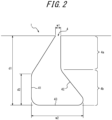
- shoulder groove 4 Further details of the shoulder groove 4 are described below with reference to Figures 1 , 2 , and 3 , using the shoulder groove 4 in the shoulder land portion 3a as a typical example.
- Figure 2 is a cross-sectional view along the line A-A in Figure 1
- Figure 3 is a schematic perspective view for explaining the shape of the shoulder groove.
- the shoulder groove 4 extends along the tire width direction WD on the tread surface 1.
- extending "along the tire width direction” means that the shoulder groove 4 is parallel to the tire width direction WD in the tire plane view, or the shoulder groove 4 extends at an angle of 5° or less with respect to the tire width direction.
- the shoulder groove 4 may extend in a straight line in the tire width direction as illustrated in Figure 1 , or it may extend in a zigzag or wavy pattern, etc. in the tire width direction.
- zigzag pattern in the tire width direction means that each of the linear portions constituting the zigzag pattern extends along the tire width direction.
- the shoulder groove 4 opens at the tread edge TE of the shoulder land portion 3a, extends toward the circumferential main groove 2a, and terminates in the shoulder land portion 3a.
- the configuration of the shoulder groove 4 is not limited to this, for example, it may open to both the tread edge TE and the circumferential main groove 2a.
- groove width of the shoulder groove 4 at the tread surface 1 is not particularly limited.
- the shoulder groove 4 has a widened section on the groove bottom side where the groove width is larger than that on the tread surface 1 side.
- this embodiment has a first widened section 4a on the groove bottom 43 side (in the example illustrated in the figure, in the bottom direction of the paper), where the groove width is larger than that of the tread surface 1 side; and a second widened section 4b on the groove bottom side than the first widened section 4a, where the groove width is larger than that on the first widened section 4a.
- the shape of the first widened section 4a and 4b is not limited to a particular shape.
- the first widened section 4a may be shaped so that the groove width increases in steps from the tread surface 1 toward the second widened section 4b side, or the groove 4 may have a constant groove width without widening from the tread surface 1 to the second widened section 4b.
- the groove 4 may be shaped in a cross-sectional view to have a maximum width portion near the groove bottom 43, with the groove width increasing in steps from the tread surface 1 side to the groove bottom 43 side.
- the shape of the second widened section 4b is not limited, and the cross-sectional shape of the second widened section 4b may be rectangular or otherwise have a constant groove width from the first widened section 4a side to the groove bottom 43.
- the cross-sectional shape of the second widened section 4b may be circular or elliptical, for example, with a maximum width portion halfway from the first widened section 4a side to the groove bottom 43 side.
- the shoulder groove 4 may have the boundaries of the groove walls 41 and 42 and the groove bottom 43 as arc-shaped side walls and groove bottom having any radius of curvature, as illustrated in Figure 2 , or the groove walls 41 and 42 and the groove bottom 43 may each be straight in a cross section perpendicular to the extending direction of the groove.
- the shoulder groove 4 extends along the tire width direction WD on the tread surface 1, as illustrated in Figure 1 .
- the maximum width portion Pw in the tire radial direction of the second widened section 4b of the shoulder groove 4 is configured so that the inclination angle ⁇ 1 with respect to the tire width direction WD is 25° or more in a plane view of the tread surface 1 (i.e., it extends at an angle of 25° or more with respect to the tire width direction WD).
- the maximum width portion (Pw) of the second widened section 4b means the portion of the shoulder groove 4 where the distance between a pair of mutually opposing groove wall surfaces when measured, in the reference condition, perpendicular to the extending direction of the second widened section 4b is the largest.
- the inclination angle ⁇ 1 of the maximum width portion Pw in a plan view of the tread surface 1 means the inclination angle of the line segment connecting one end of the shoulder groove 4 (in the example illustrated in Figure 1 , the one end in the tire width direction) and the other end of the shoulder groove 4 (in the example illustrated in Figure 1 , the other end in the tire width direction) with respect to the tire width direction WD, as illustrated in Figure 1 (in the example in Figure 1 , the line segment connecting the center in the groove width direction of one end of the shoulder groove 4 with the center in the groove width direction of the other end of the shoulder groove 4).
- the shoulder groove 4 extends along the tire width direction WD at the tread surface 1 and continuously changes its inclination angle with respect to the tire width direction WD from the tread surface 1 toward the groove bottom side, so that the inclination angle ⁇ 1 is to be 25° or more.
- the shoulder groove 4 is not limited to this configuration and may be configured so that the portion from the tread surface 1 to the second widened section 4b extends along the tire width direction WD and the second widened section 4b extends at a constant inclination angle ⁇ 1.
- the shoulder groove 4 may be configured to have a stepwise angle change from the tread surface 1 to the groove bottom.
- the shoulder grooves 4 extending along the tire width direction WD on the tread surface 1 in the shoulder land portions 3a and 3b which are located on the outermost side in the tire width direction. Since the shoulder groove 4 extends along the tire width direction WD, the tire 10 will be grounded along the contour line of the stepping-in side of the ground contact patch when the tire 10 is moving straight ahead, thereby reducing uneven wear and noise generation at the edge of shoulder groove 4.
- the shoulder groove 4 has the widened section (in this embodiment, the first widened section 4a and the second widened section 4b) on the groove bottom side, where the groove width is larger than that on the tread surface 1 side, thus ensuring sufficient drainage performance when tire wear has progressed.
- the shoulder groove 4 is inclined at more than 25° with respect to the tire width direction WD when tire wear has progressed.
- the outer contour line of the contact patch changes from the state before wear progressed, as illustrated by the dotted line C1 in Figure 1 .
- the drainage performance of the grooves tends to increase as the grooves extend in a direction perpendicular to the outer contour line of the contact patch at a position closer to the stepping-in side of the tire.
- the shoulder groove 4 extends along the tire width direction before tire wear progresses, and the shoulder groove 4 (the second widened section 4b in this embodiment) extends at an angle of 25° or more with respect to the tire width direction after tire wear has progressed. This promotes, after tire wear has progressed, drainage from the inside in the tier width direction toward the tread edge TE side of the tire, at the timing that the groove is approximately perpendicular to the outer contour line of the ground contact patch, when the shoulder groove 4 is closer to the stepping-in side of the tire as the tire rotates.
- the shoulder grooves 4 in the shoulder land portion drainage toward the tread edge TE is more easily facilitated than when they are disposed in the center land portion, and sufficient drainage performance can be ensured when tire wear has progressed.
- the groove depth d1 of the shoulder groove 4 is not particularly limited, but from the viewpoint of ensuring sufficient drainage performance and maintaining tire rigidity, it is preferable to make it as deep as the circumferential main grooves 2a and 2b. More specifically, the groove depth d1 is preferably, for example, 3 mm or more and 20 mm or less. More preferably, it is 5 mm or more and 10 mm or less.
- the length d2 of the second widened section 4b of the shoulder groove 4 in the groove depth direction is not particularly limited, but from the viewpoint of maintaining sufficient rigidity of the shoulder land portion where the shoulder groove 4 is provided while effectively ensuring sufficient drainage performance, the length d2 is preferably 30% or more and 70% or less of the overall depth d1 of the shoulder groove 4. More preferably, the length d2 is 40% or more and 60% or less of the groove depth d1.
- the groove width w1 of the shoulder groove 4 on the tread surface 1 is not particularly limited, but from the viewpoint of effectively maintaining the rigidity of the tire when new, it is suitable to be less than 1.5 mm in the reference condition. From the standpoint of ensuring sufficient drainage performance of the shoulder groove 4, it is suitably at least 1 mm.
- the groove width w2 of the maximum width portion Pw of the second widened section 4b of the shoulder groove 4 is not particularly limited, but from the viewpoint of sufficient drainage performance when tire wear has progressed, for example, the groove width w2 can be 1.5 mm or more, and from the viewpoint of maintaining sufficient rigidity of the shoulder land portion in which the shoulder groove 4 is provided, for example, it is suitably 4 mm or less. More suitably, the groove width w2 is 2.0 mm or more and 3.5 mm or less from the viewpoint of both sufficient drainage performance and maintaining the rigidity of the land portions when tire wear has progressed.
- the extension length L1 of the shoulder groove 4 on the tread surface 1 is not particularly limited, but is preferably at least 25% of the ground contact width TW of the tire. By setting the extension length L1 to 25% or more of the ground contact width TW of the tire, water from the road surface can be fully captured in the grooves and sufficient drainage performance can be effectively ensured.
- the number of the shoulder grooves 4 is not particularly limited, but from the viewpoint of ensuring sufficient drainage performance, it is preferable that two or more grooves are arranged on the shoulder land portions 3a and 3b, respectively, within the contact patch of the tire. More preferably, from the viewpoint of ensuring sufficient drainage performance and rigidity of the land portion where the shoulder grooves 4 are provided, three to ten grooves are preferably arranged in the shoulder land portions 3a and 3b, respectively, within the contact patch.
- the term "arranged within the contact patch” shall mean that the shoulder groove 4 is arranged within the contact patch if any part of the shoulder groove 4 is located within the contact patch.
- the inclination angle (angle on the acute side) ⁇ 1 of the maximum width portion Pw in the tire radial direction of the second widened section 4b of the shoulder groove 4 with respect to the tire circumferential direction WD in a plan view of the tread surface 1 is not particularly limited as long as it is 25° or more, but it is preferably 50° or less in order to effectively ensure sufficient drainage performance while maintaining the sufficient circumferential traction performance of the tire. More suitably, the inclination angle ⁇ 1 of the second widened section 4b is 28° or more and 45° or less.
- the direction of rotation of the tire 10 is not particularly limited, it is preferable that the tire 10 be mounted so that it rotates in the direction of tire circumferential direction CD1 in Figure 1 , or that the tire 10 is a tire which is specified or recommended to be mounted to rotate in that direction, to promote more effective drainage from the inside edge in the tire width direction of the shoulder groove 4 to the tread edge TE side when tire wear has progressed.
- Such mounting promotes more effective drainage by the second widened section 4b of shoulder groove 4 from the stepping-in side to the kicking-out side of the contact patch of the tire. Furthermore, after the tire wear progresses, the grooves will be sloped and extending in the direction of water drainage from the stepping-in side of the contact patch of the tire, which will provide sufficient wet grip with the road surface.
- the tire 20 of the second embodiment has the same configuration as the tire of the first embodiment, except that the shoulder land portion has a different configuration. Therefore, the components similar to those in the first embodiment are given the same reference numerals and their descriptions will be omitted.
- Figure 4 schematically illustrates the contact patch of a tire 20 according to the second embodiment of this disclosure.
- the grooves in a plan view of the tread surface 11 when tire wear has progressed are also indicated by dotted lines.
- shoulder land portions 30a and 30b are divided by the pair of circumferential main grooves 2a located at the outermost side in the tire width direction, and the tread edges TE, and center land portions 3c and 3d are divided by the circumferential main groove 2b and a pair of circumferential main grooves 2a.
- the shoulder land portions 30a and 30b are divided into a plurality of block land portions 301a and 301b by a plurality of width direction grooves 50 (in this embodiment, within the contact patch, two of the width direction grooves 50 in the shoulder land portions 30a and 30b, respectively) extending in the tire width direction and connected to the tread edge TE and the circumferential main groove 2a (in this embodiment, there is one block land portion 301a and 301b each in which the entire block land portion is located within the contact patch, and there are two block land portions 301a and 301b each in which a portion of the block land portion is located within the contact patch).
- the width direction grooves 50 may extend parallel to the tire width direction WD in the tire plane view, or may extend at an inclination angle of 45° or less with respect to the tire width direction WD. Also, the width direction grooves 50 may extend in a straight line in the tire width direction, as illustrated in Figure 4 , or may extend in a zigzag or wavy pattern, etc. in the tire width direction.
- the number of block land portions disposed within the contact patch is not particularly limited, but it is preferred that two to ten of the block land portions 301a and 301b are arranged within the contact patch of the tire, respectively.
- the term "arranged within the contact patch” shall mean that the block land portions 301a and 301b are arranged within the contact patch if any part of the block land portions are located within the contact patch.
- one or more shoulder grooves 4 are arranged in the block land portions 301a and 301b respectively, from the viewpoint of effectively ensuring sufficient drainage performance when tire wear has progressed.
- the number of the shoulder grooves 4 is preferably no more than three in the block land portions 301a and 301b respectively, from the viewpoint of maintaining sufficient rigidity of the block land portions where the shoulder grooves 4 are arranged.
- the tire of the present disclosure can be used for any type of tire, but can suitably be used for passenger car tires.
Landscapes
- Engineering & Computer Science (AREA)
- Mechanical Engineering (AREA)
- Tires In General (AREA)
Abstract
Description
- This disclosure relates to a tire.
- This application claims priority based on Patent Application No.
2021-154870 filed in Japan on September 22, 2021 - Tires having sipes whose width at the bottom portion is widened in order to control the decrease in drainage performance of the tire when tire wear has progressed, have been disclosed (Patent Document 1).
- PTL 1:
JP 2018-111421 A - However, there is room for further improvement in the prior art with regard to drainage performance when tire wear has progressed.
- Therefore, the purpose of the present disclosure is to provide a tire with sufficient drainage performance even when tire wear has progressed.
- The gist of the present disclosure is as follows.
- A tire having a plurality of circumferential main grooves extending in the tire circumferential direction on a tread surface,
- at least one shoulder groove is provided in a shoulder land portion, which is divided by the circumferential main groove located at the outermost side in the tire width direction and a tread edge,
- the shoulder groove has a widened section on the groove bottom side where a groove width is larger than that on the tread surface side,
- the shoulder groove extends along the tire width direction on the tread surface, and
- a maximum width portion in the tire radial direction of the widened section extends at an angle of 25° or more with respect to the tire width direction in a plane view of the tread surface.
- The present disclosure can provide a tire with sufficient drainage performance even when tire wear has progressed.
- In the accompanying drawings:
-
FIG. 1 schematically illustrates the contact patch of a tire according to the first embodiment of this disclosure, viewed in the tire axial direction; -
FIG. 2 is a cross-sectional view along the line A-A inFIG. 1 ; -
FIG. 3 is a schematic perspective view for explaining the shape of the shoulder groove; and -
FIG. 4 schematically illustrates the contact patch of a tire according to the second embodiment of this disclosure. - The tire of the present disclosure can be used for any type of tire, but can suitably be used for passenger car tires.
- The following is illustrative descriptions of embodiments of the tire according to the present disclosure, with reference to the drawings. In each figure, common components are given the same reference numerals.
-
Figure 1 schematically illustrates the contact patch of atire 10 according to the first embodiment of this disclosure, viewed in the tire axial direction. InFigure 1 , the grooves in a plan view of the tread surface 1 when tire wear has progressed are also indicated by dotted lines. Also, inFigure 1 , the outer contour line of the contact patch when tire wear has progressed is schematically indicated by the dotted line C1. - As used herein, the term "tread surface (1)" means the outer circumferential surface of the tire that is in contact with the road surface when the tire is assembled on a rim, filled with prescribed internal pressure, and rolled under a maximum load.
- In this document, the term "tread edge (TE)" means the outer edge of the tread surface (1) in the tire width direction.
- As used herein, the term "rim" refers to the standard rim in the applicable size (Measuring Rim in ETRTO's STANDARDS MANUAL and Design Rim in TRA's YEAR BOOK) as described or as may be described in the future in the industrial standard, which is valid for the region in which the tire is produced and used, such as JATMA YEAR BOOK of JATMA (Japan Automobile Tyre Manufacturers Association) in Japan, STANDARDS MANUAL of ETRTO (The European Tyre and Rim Technical Organization) in Europe, and YEAR BOOK of TRA (The Tire and Rim Association, Inc.) in the United States (That is, the term "rim" includes current sizes as well as future sizes to be listed in the aforementioned industrial standards. An example of the "size as described in the future" could be the sizes listed as "FUTURE DEVELOPMENTS" in the ETRTO 2013 edition.). For sizes not listed in these industrial standards, the term "applicable rim" refers to a rim with a width corresponding to the bead width of the pneumatic tire.
- Also, the term "prescribed internal pressure" refers to the air pressure (maximum air pressure) corresponding to the maximum load capacity of a single wheel in the applicable size and ply rating, as described in the aforementioned JATMA YEAR BOOK and other industrial standards. In the case that the size is not listed in the aforementioned industrial standards, the "prescribed internal pressure" refers to the air pressure (maximum air pressure) corresponding to the maximum load capacity specified for each vehicle in which the tire is mounted.
- The term "maximum load" refers to the load corresponding to the above maximum load capacity.
- The air here can be replaced by inert gas such as nitrogen gas or other inert gas.
- In this document, unless otherwise noted, the dimensions of each element such as grooves and land portions, ground width (TW), etc., shall be measured in the "reference condition" described below.
- As used herein, the term "reference condition" refers to the condition in which the tire is assembled on the rim, filled with the above prescribed internal pressure, and unloaded.
- In this document, the term "groove width" refers to the distance between a pair of mutually opposing groove wall surfaces when measured perpendicularly to the extending direction of the groove. As used herein, the term "groove depth" refers to the distance from the tread surface to the groove bottom position in a cross-section along the groove width direction, in the direction perpendicular to the tread surface.
- Also, in this document, the term "contact patch" shall mean the outer surface of the tire that contacts the road surface when the tire is assembled on the rim, filled with the prescribed internal pressure, and grounded with the maximum load applied.
- As used herein, the term "tire circumferential direction" is also referred to as "tire circumferential direction CD1" or "tire circumferential direction CD2", and the term "tire width direction" is also referred to as "tire width direction WD". In each figure, the tire circumferential direction (CD) is indicated by the arrows CD1 and CD2, and the tire width direction (WD) is indicated by the arrow WD.
- As illustrated in
Figure 1 , thetire 10 according to the first embodiment of this disclosure has a plurality of circumferentialmain grooves 2 extending in the tire circumferential direction on the tread surface. In this embodiment, a pair of circumferentialmain grooves 2a arranged at the outermost sides in the tire width direction and a circumferentialmain groove 2b extending along the tire equatorial plane CL are arranged. In the example illustrated inFigure 1 , the number of circumferentialmain grooves 2 is three, but it can be two or four or more. - In the tread plane view of the tread surface 1 of the
tire 10 according to this embodiment, both circumferentialmain grooves main groove 2 may extend at an angle with respect to the tire circumferential direction. In such a case, the circumferential main groove may extend at an angle of, for example, 5° or less with respect to the tire circumferential direction. In addition, each circumferentialmain groove 2 may extend in a straight line along the tire circumferential direction, as illustrated inFigure 1 , or it may extend circumferentially in a zigzag or wavy shape, etc. - The widths of the circumferential
main grooves - Also, the groove depths of the circumferential
main grooves - On the tread surface 1 of the
tire 10 of this embodiment,shoulder land portions main grooves 2a located at the outermost side in the tire width direction, and the tread edges TE; andcenter land portions main groove 2b and the pair of circumferentialmain grooves 2a. - In the
tire 10 of this embodiment, theshoulder land portions center land portions - In the example illustrated in
Figure 1 , thecenter land portions - In the
tire 10 of this embodiment, at least oneshoulder groove 4 is provided in theshoulder land portions Figure 1 , theshoulder grooves 4 are provided within a contact patch, two each in theshoulder land portions shoulder grooves 4 are not limited. For example, only one of theshoulder land portions shoulder groove 4. - Further details of the
shoulder groove 4 are described below with reference toFigures 1 ,2 , and3 , using theshoulder groove 4 in theshoulder land portion 3a as a typical example. -
Figure 2 is a cross-sectional view along the line A-A inFigure 1 , andFigure 3 is a schematic perspective view for explaining the shape of the shoulder groove. - In this embodiment, the
shoulder groove 4 extends along the tire width direction WD on the tread surface 1. Here, extending "along the tire width direction" means that theshoulder groove 4 is parallel to the tire width direction WD in the tire plane view, or theshoulder groove 4 extends at an angle of 5° or less with respect to the tire width direction. Theshoulder groove 4 may extend in a straight line in the tire width direction as illustrated inFigure 1 , or it may extend in a zigzag or wavy pattern, etc. in the tire width direction. Here, "zigzag pattern in the tire width direction" means that each of the linear portions constituting the zigzag pattern extends along the tire width direction. - In the example illustrated in
Figure 1 , theshoulder groove 4 opens at the tread edge TE of theshoulder land portion 3a, extends toward the circumferentialmain groove 2a, and terminates in theshoulder land portion 3a. However, the configuration of theshoulder groove 4 is not limited to this, for example, it may open to both the tread edge TE and the circumferentialmain groove 2a. - Note, that the groove width of the
shoulder groove 4 at the tread surface 1 is not particularly limited. - The
shoulder groove 4 has a widened section on the groove bottom side where the groove width is larger than that on the tread surface 1 side. As illustrated inFigure 2 , this embodiment has a first widenedsection 4a on the groove bottom 43 side (in the example illustrated in the figure, in the bottom direction of the paper), where the groove width is larger than that of the tread surface 1 side; and a second widenedsection 4b on the groove bottom side than the first widenedsection 4a, where the groove width is larger than that on the first widenedsection 4a. The shape of the first widenedsection - For example, as illustrated in
Figure 2 , the first widenedsection 4a may be shaped so that the groove width increases in steps from the tread surface 1 toward the second widenedsection 4b side, or thegroove 4 may have a constant groove width without widening from the tread surface 1 to the second widenedsection 4b. - In addition, as illustrated in
Figure 2 , thegroove 4 may be shaped in a cross-sectional view to have a maximum width portion near the groove bottom 43, with the groove width increasing in steps from the tread surface 1 side to the groove bottom 43 side. The shape of the second widenedsection 4b is not limited, and the cross-sectional shape of the second widenedsection 4b may be rectangular or otherwise have a constant groove width from the first widenedsection 4a side to thegroove bottom 43. In addition, the cross-sectional shape of the second widenedsection 4b may be circular or elliptical, for example, with a maximum width portion halfway from the first widenedsection 4a side to the groove bottom 43 side. - The
shoulder groove 4 may have the boundaries of thegroove walls Figure 2 , or thegroove walls - As mentioned above, in the
tire 10 of the first embodiment, theshoulder groove 4 extends along the tire width direction WD on the tread surface 1, as illustrated inFigure 1 . On the other hand, as illustrated by the dotted line inFigure 1 , the maximum width portion Pw in the tire radial direction of the second widenedsection 4b of theshoulder groove 4 is configured so that the inclination angle θ1 with respect to the tire width direction WD is 25° or more in a plane view of the tread surface 1 (i.e., it extends at an angle of 25° or more with respect to the tire width direction WD). - Here, the maximum width portion (Pw) of the second widened
section 4b means the portion of theshoulder groove 4 where the distance between a pair of mutually opposing groove wall surfaces when measured, in the reference condition, perpendicular to the extending direction of the second widenedsection 4b is the largest. - In addition, the inclination angle θ1 of the maximum width portion Pw in a plan view of the tread surface 1 means the inclination angle of the line segment connecting one end of the shoulder groove 4 (in the example illustrated in
Figure 1 , the one end in the tire width direction) and the other end of the shoulder groove 4 (in the example illustrated inFigure 1 , the other end in the tire width direction) with respect to the tire width direction WD, as illustrated inFigure 1 (in the example inFigure 1 , the line segment connecting the center in the groove width direction of one end of theshoulder groove 4 with the center in the groove width direction of the other end of the shoulder groove 4). - As illustrated in
Figure 3 , in thetire 10 of this embodiment, theshoulder groove 4 extends along the tire width direction WD at the tread surface 1 and continuously changes its inclination angle with respect to the tire width direction WD from the tread surface 1 toward the groove bottom side, so that the inclination angle θ1 is to be 25° or more. Theshoulder groove 4 is not limited to this configuration and may be configured so that the portion from the tread surface 1 to the second widenedsection 4b extends along the tire width direction WD and the second widenedsection 4b extends at a constant inclination angle θ1. Also, theshoulder groove 4 may be configured to have a stepwise angle change from the tread surface 1 to the groove bottom. - The effects of the tire of the first embodiment are described below.
- According to the
tire 10 of this embodiment, drainage performance can be ensured by disposing theshoulder grooves 4 extending along the tire width direction WD on the tread surface 1 in theshoulder land portions shoulder groove 4 extends along the tire width direction WD, thetire 10 will be grounded along the contour line of the stepping-in side of the ground contact patch when thetire 10 is moving straight ahead, thereby reducing uneven wear and noise generation at the edge ofshoulder groove 4. - In addition, the
shoulder groove 4 has the widened section (in this embodiment, the first widenedsection 4a and the second widenedsection 4b) on the groove bottom side, where the groove width is larger than that on the tread surface 1 side, thus ensuring sufficient drainage performance when tire wear has progressed. - Furthermore, the
shoulder groove 4 is inclined at more than 25° with respect to the tire width direction WD when tire wear has progressed. When tire wear has progressed, the outer contour line of the contact patch changes from the state before wear progressed, as illustrated by the dotted line C1 inFigure 1 . The drainage performance of the grooves tends to increase as the grooves extend in a direction perpendicular to the outer contour line of the contact patch at a position closer to the stepping-in side of the tire. Therefore, in this embodiment, as illustrated inFigure 1 , theshoulder groove 4 extends along the tire width direction before tire wear progresses, and the shoulder groove 4 (the second widenedsection 4b in this embodiment) extends at an angle of 25° or more with respect to the tire width direction after tire wear has progressed. This promotes, after tire wear has progressed, drainage from the inside in the tier width direction toward the tread edge TE side of the tire, at the timing that the groove is approximately perpendicular to the outer contour line of the ground contact patch, when theshoulder groove 4 is closer to the stepping-in side of the tire as the tire rotates. In addition, by providing theshoulder grooves 4 in the shoulder land portion, drainage toward the tread edge TE is more easily facilitated than when they are disposed in the center land portion, and sufficient drainage performance can be ensured when tire wear has progressed. - The following is a description of suitable configurations, variations, etc., of the tire of the first embodiment.
- The groove depth d1 of the
shoulder groove 4 is not particularly limited, but from the viewpoint of ensuring sufficient drainage performance and maintaining tire rigidity, it is preferable to make it as deep as the circumferentialmain grooves - The length d2 of the second widened
section 4b of theshoulder groove 4 in the groove depth direction is not particularly limited, but from the viewpoint of maintaining sufficient rigidity of the shoulder land portion where theshoulder groove 4 is provided while effectively ensuring sufficient drainage performance, the length d2 is preferably 30% or more and 70% or less of the overall depth d1 of theshoulder groove 4. More preferably, the length d2 is 40% or more and 60% or less of the groove depth d1. - The groove width w1 of the
shoulder groove 4 on the tread surface 1 is not particularly limited, but from the viewpoint of effectively maintaining the rigidity of the tire when new, it is suitable to be less than 1.5 mm in the reference condition. From the standpoint of ensuring sufficient drainage performance of theshoulder groove 4, it is suitably at least 1 mm. - The groove width w2 of the maximum width portion Pw of the second widened
section 4b of theshoulder groove 4 is not particularly limited, but from the viewpoint of sufficient drainage performance when tire wear has progressed, for example, the groove width w2 can be 1.5 mm or more, and from the viewpoint of maintaining sufficient rigidity of the shoulder land portion in which theshoulder groove 4 is provided, for example, it is suitably 4 mm or less. More suitably, the groove width w2 is 2.0 mm or more and 3.5 mm or less from the viewpoint of both sufficient drainage performance and maintaining the rigidity of the land portions when tire wear has progressed. - The extension length L1 of the
shoulder groove 4 on the tread surface 1 is not particularly limited, but is preferably at least 25% of the ground contact width TW of the tire. By setting the extension length L1 to 25% or more of the ground contact width TW of the tire, water from the road surface can be fully captured in the grooves and sufficient drainage performance can be effectively ensured. - The number of the
shoulder grooves 4 is not particularly limited, but from the viewpoint of ensuring sufficient drainage performance, it is preferable that two or more grooves are arranged on theshoulder land portions shoulder grooves 4 are provided, three to ten grooves are preferably arranged in theshoulder land portions - Here, the term "arranged within the contact patch" shall mean that the
shoulder groove 4 is arranged within the contact patch if any part of theshoulder groove 4 is located within the contact patch. - The inclination angle (angle on the acute side) θ1 of the maximum width portion Pw in the tire radial direction of the second widened
section 4b of theshoulder groove 4 with respect to the tire circumferential direction WD in a plan view of the tread surface 1 is not particularly limited as long as it is 25° or more, but it is preferably 50° or less in order to effectively ensure sufficient drainage performance while maintaining the sufficient circumferential traction performance of the tire. More suitably, the inclination angle θ1 of the second widenedsection 4b is 28° or more and 45° or less. - Although the direction of rotation of the
tire 10 is not particularly limited, it is preferable that thetire 10 be mounted so that it rotates in the direction of tire circumferential direction CD1 inFigure 1 , or that thetire 10 is a tire which is specified or recommended to be mounted to rotate in that direction, to promote more effective drainage from the inside edge in the tire width direction of theshoulder groove 4 to the tread edge TE side when tire wear has progressed. In the example inFigure 1 , this means, after the tire wear progresses, that the tire is rotated so that the maximum width portion Pw slopes from the stepping-in side to the kicking-out side of the tire as it moves from the inside to the outside of the tire width direction. Such mounting promotes more effective drainage by the second widenedsection 4b ofshoulder groove 4 from the stepping-in side to the kicking-out side of the contact patch of the tire. Furthermore, after the tire wear progresses, the grooves will be sloped and extending in the direction of water drainage from the stepping-in side of the contact patch of the tire, which will provide sufficient wet grip with the road surface. - Next, the tire according to the other embodiment of this disclosure (the second embodiment) is described with reference to
Figure 4 . Thetire 20 of the second embodiment has the same configuration as the tire of the first embodiment, except that the shoulder land portion has a different configuration. Therefore, the components similar to those in the first embodiment are given the same reference numerals and their descriptions will be omitted. -
Figure 4 schematically illustrates the contact patch of atire 20 according to the second embodiment of this disclosure. InFigure 4 , the grooves in a plan view of the tread surface 11 when tire wear has progressed are also indicated by dotted lines. - On the tread surface 11 of the
tire 20 of this embodiment,shoulder land portions main grooves 2a located at the outermost side in the tire width direction, and the tread edges TE, andcenter land portions main groove 2b and a pair of circumferentialmain grooves 2a. - The
shoulder land portions block land portions width direction grooves 50 in theshoulder land portions main groove 2a (in this embodiment, there is oneblock land portion block land portions - The
width direction grooves 50 may extend parallel to the tire width direction WD in the tire plane view, or may extend at an inclination angle of 45° or less with respect to the tire width direction WD. Also, thewidth direction grooves 50 may extend in a straight line in the tire width direction, as illustrated inFigure 4 , or may extend in a zigzag or wavy pattern, etc. in the tire width direction. - In the
tire 20 of this embodiment, the number of block land portions disposed within the contact patch is not particularly limited, but it is preferred that two to ten of theblock land portions block land portions - Here, the term "arranged within the contact patch" shall mean that the
block land portions - In the
tire 20 of this embodiment, it is preferable that one ormore shoulder grooves 4 are arranged in theblock land portions shoulder grooves 4 is preferably no more than three in theblock land portions shoulder grooves 4 are arranged. - The tire of the present disclosure can be used for any type of tire, but can suitably be used for passenger car tires.
-
- 1, 11
- Tread surface
- 2, 2a, 2b
- Circumferential main groove
- 3a, 3b, 30a, 30b
- Shoulder land portion
- 3c, 3d
- Center land portion
- 4
- Shoulder groove
- 4a
- Widened section
- 4b
- Narrowed groove section
- 10, 20
- Tire
- 41, 42
- Groove wall
- 43
- Groove bottom
- 50
- Width direction groove
- 301a, 301b
- Block land portion
- Pw
- Maximum width portion
- WD
- Tire width direction
- CD1, CD2
- Tire circumferential direction
- TE
- Tread edge
Claims (6)
- A tire having a plurality of circumferential main grooves extending in the tire circumferential direction on a tread surface,at least one shoulder groove is provided in a shoulder land portion, which is divided by the circumferential main groove located at the outermost side in the tire width direction and a tread edge,the shoulder groove has a widened section on the groove bottom side where a groove width is larger than that on the tread surface side,the shoulder groove extends along the tire width direction on the tread surface, anda maximum width portion in the tire radial direction of the widened section extends at an angle of 25° or more with respect to the tire width direction in a plane view of the tread surface.
- The tire according to claim 1, wherein a groove width on the tread surface of the shoulder groove is less than 1.5 mm.
- The tire according to claim 1 or 2, wherein extension length on the tread surface of the shoulder groove is 25% or more of a ground contact width of the tire.
- The tire according to any one of claims 1 to 3, wherein three to ten of the shoulder grooves are arranged in the shoulder land portion within a contact patch of the tire.
- The tire according to any one of claims 1 to 4, wherein the shoulder land portion is divided into a plurality of block land portions by a plurality of width direction grooves extending in the tire width direction and connected to the tread edge and the circumferential main groove, and
two to ten of the block land portions are arranged within a contact patch of the tire. - The tire according to claim 5, wherein one to three of the shoulder grooves are arranged in each of the block land portions.
Applications Claiming Priority (2)
| Application Number | Priority Date | Filing Date | Title |
|---|---|---|---|
| JP2021154870A JP7721380B2 (en) | 2021-09-22 | 2021-09-22 | tire |
| PCT/JP2022/024414 WO2023047722A1 (en) | 2021-09-22 | 2022-06-17 | Tire |
Publications (3)
| Publication Number | Publication Date |
|---|---|
| EP4406759A1 true EP4406759A1 (en) | 2024-07-31 |
| EP4406759A4 EP4406759A4 (en) | 2024-12-25 |
| EP4406759B1 EP4406759B1 (en) | 2025-12-17 |
Family
ID=85720431
Family Applications (1)
| Application Number | Title | Priority Date | Filing Date |
|---|---|---|---|
| EP22872480.3A Active EP4406759B1 (en) | 2021-09-22 | 2022-06-17 | Tire |
Country Status (5)
| Country | Link |
|---|---|
| US (1) | US20250074119A1 (en) |
| EP (1) | EP4406759B1 (en) |
| JP (1) | JP7721380B2 (en) |
| CN (1) | CN117980157A (en) |
| WO (1) | WO2023047722A1 (en) |
Family Cites Families (14)
| Publication number | Priority date | Publication date | Assignee | Title |
|---|---|---|---|---|
| JPH01101205A (en) * | 1987-10-12 | 1989-04-19 | Bridgestone Corp | Pneumatic tire |
| JPH0632114A (en) * | 1992-07-14 | 1994-02-08 | Yokohama Rubber Co Ltd:The | Pneumatic tire |
| JPH06143943A (en) * | 1992-11-05 | 1994-05-24 | Yokohama Rubber Co Ltd:The | Pneumatic tire |
| JPH11208223A (en) * | 1998-01-28 | 1999-08-03 | Bridgestone Corp | Pneumatic tire |
| JP5374565B2 (en) * | 2011-10-28 | 2013-12-25 | 住友ゴム工業株式会社 | Pneumatic tire |
| JP2015101211A (en) * | 2013-11-25 | 2015-06-04 | 横浜ゴム株式会社 | Pneumatic tire |
| FR3039097B1 (en) * | 2015-07-24 | 2017-07-21 | Michelin & Cie | HEAVY-WEIGHT TIRE TREADBAND IMPROVING ROLLING NOISE |
| JP7081185B2 (en) | 2018-02-05 | 2022-06-07 | 住友ゴム工業株式会社 | tire |
| JP7116014B2 (en) * | 2019-06-12 | 2022-08-09 | 株式会社ブリヂストン | pneumatic tire |
| JP7116016B2 (en) * | 2019-06-14 | 2022-08-09 | 株式会社ブリヂストン | pneumatic tire |
| JP7116709B2 (en) * | 2019-06-14 | 2022-08-10 | 株式会社ブリヂストン | pneumatic tire |
| JP7333253B2 (en) | 2019-12-05 | 2023-08-24 | 株式会社ブリヂストン | pneumatic tire |
| JP7332453B2 (en) | 2019-12-05 | 2023-08-23 | 株式会社ブリヂストン | pneumatic tire |
| JP7316245B2 (en) | 2020-03-27 | 2023-07-27 | 日立Astemo株式会社 | Vehicle control system and vehicle control device |
-
2021
- 2021-09-22 JP JP2021154870A patent/JP7721380B2/en active Active
-
2022
- 2022-06-17 EP EP22872480.3A patent/EP4406759B1/en active Active
- 2022-06-17 CN CN202280064421.3A patent/CN117980157A/en active Pending
- 2022-06-17 WO PCT/JP2022/024414 patent/WO2023047722A1/en not_active Ceased
- 2022-06-17 US US18/684,836 patent/US20250074119A1/en active Pending
Also Published As
| Publication number | Publication date |
|---|---|
| EP4406759B1 (en) | 2025-12-17 |
| US20250074119A1 (en) | 2025-03-06 |
| JP7721380B2 (en) | 2025-08-12 |
| WO2023047722A1 (en) | 2023-03-30 |
| CN117980157A (en) | 2024-05-03 |
| EP4406759A4 (en) | 2024-12-25 |
| JP2023046133A (en) | 2023-04-03 |
Similar Documents
| Publication | Publication Date | Title |
|---|---|---|
| EP3118025B1 (en) | Pneumatic tire | |
| EP3023268B1 (en) | Heavy duty tire | |
| EP3260308B1 (en) | Tire | |
| CN107053957B (en) | Pneumatic tire | |
| EP2614966B1 (en) | Heavy duty pneumatic tire | |
| EP3095623B1 (en) | Pneumatic tire | |
| EP2732985B1 (en) | Pneumatic tire | |
| EP3213930B1 (en) | Pneumatic tire | |
| EP3012119B1 (en) | Pneumatic tire | |
| EP2982520B1 (en) | Pneumatic tire | |
| EP3521064B1 (en) | Tyre | |
| EP3078506B1 (en) | Pneumatic tire | |
| US10272725B2 (en) | Pneumatic tire | |
| EP3375633B1 (en) | Tire | |
| EP3354483B1 (en) | Tire | |
| EP2777950B1 (en) | Pneumatic tire | |
| EP3335910B1 (en) | Tire | |
| EP2738019A1 (en) | Tire | |
| EP3409507B1 (en) | Tire | |
| EP2689940B1 (en) | Pneumatic tire | |
| EP4265441A1 (en) | Pneumatic tire | |
| EP3305554B1 (en) | Pneumatic tire | |
| US20250074119A1 (en) | Tire | |
| EP3995327B1 (en) | Pneumatic tire | |
| EP3988331A1 (en) | Pneumatic tire |
Legal Events
| Date | Code | Title | Description |
|---|---|---|---|
| STAA | Information on the status of an ep patent application or granted ep patent |
Free format text: STATUS: THE INTERNATIONAL PUBLICATION HAS BEEN MADE |
|
| PUAI | Public reference made under article 153(3) epc to a published international application that has entered the european phase |
Free format text: ORIGINAL CODE: 0009012 |
|
| STAA | Information on the status of an ep patent application or granted ep patent |
Free format text: STATUS: REQUEST FOR EXAMINATION WAS MADE |
|
| 17P | Request for examination filed |
Effective date: 20240229 |
|
| AK | Designated contracting states |
Kind code of ref document: A1 Designated state(s): AL AT BE BG CH CY CZ DE DK EE ES FI FR GB GR HR HU IE IS IT LI LT LU LV MC MK MT NL NO PL PT RO RS SE SI SK SM TR |
|
| A4 | Supplementary search report drawn up and despatched |
Effective date: 20241121 |
|
| RIC1 | Information provided on ipc code assigned before grant |
Ipc: B60C 11/13 20060101ALI20241115BHEP Ipc: B60C 11/12 20060101ALI20241115BHEP Ipc: B60C 11/03 20060101AFI20241115BHEP |
|
| DAV | Request for validation of the european patent (deleted) | ||
| DAX | Request for extension of the european patent (deleted) | ||
| GRAP | Despatch of communication of intention to grant a patent |
Free format text: ORIGINAL CODE: EPIDOSNIGR1 |
|
| STAA | Information on the status of an ep patent application or granted ep patent |
Free format text: STATUS: GRANT OF PATENT IS INTENDED |
|
| INTG | Intention to grant announced |
Effective date: 20250718 |
|
| GRAS | Grant fee paid |
Free format text: ORIGINAL CODE: EPIDOSNIGR3 |
|
| GRAA | (expected) grant |
Free format text: ORIGINAL CODE: 0009210 |
|
| STAA | Information on the status of an ep patent application or granted ep patent |
Free format text: STATUS: THE PATENT HAS BEEN GRANTED |
|
| P01 | Opt-out of the competence of the unified patent court (upc) registered |
Free format text: CASE NUMBER: UPC_APP_9422_4406759/2025 Effective date: 20251009 |
|
| AK | Designated contracting states |
Kind code of ref document: B1 Designated state(s): AL AT BE BG CH CY CZ DE DK EE ES FI FR GB GR HR HU IE IS IT LI LT LU LV MC MK MT NL NO PL PT RO RS SE SI SK SM TR |
|
| REG | Reference to a national code |
Ref country code: CH Ref legal event code: F10 Free format text: ST27 STATUS EVENT CODE: U-0-0-F10-F00 (AS PROVIDED BY THE NATIONAL OFFICE) Effective date: 20251217 Ref country code: GB Ref legal event code: FG4D |
|
| REG | Reference to a national code |
Ref country code: DE Ref legal event code: R096 Ref document number: 602022027195 Country of ref document: DE |
|
| REG | Reference to a national code |
Ref country code: LT Ref legal event code: MG9D |
|
| PG25 | Lapsed in a contracting state [announced via postgrant information from national office to epo] |
Ref country code: NO Free format text: LAPSE BECAUSE OF FAILURE TO SUBMIT A TRANSLATION OF THE DESCRIPTION OR TO PAY THE FEE WITHIN THE PRESCRIBED TIME-LIMIT Effective date: 20260317 |
|
| PG25 | Lapsed in a contracting state [announced via postgrant information from national office to epo] |
Ref country code: FI Free format text: LAPSE BECAUSE OF FAILURE TO SUBMIT A TRANSLATION OF THE DESCRIPTION OR TO PAY THE FEE WITHIN THE PRESCRIBED TIME-LIMIT Effective date: 20251217 Ref country code: HR Free format text: LAPSE BECAUSE OF FAILURE TO SUBMIT A TRANSLATION OF THE DESCRIPTION OR TO PAY THE FEE WITHIN THE PRESCRIBED TIME-LIMIT Effective date: 20251217 |
|
| PG25 | Lapsed in a contracting state [announced via postgrant information from national office to epo] |
Ref country code: RS Free format text: LAPSE BECAUSE OF FAILURE TO SUBMIT A TRANSLATION OF THE DESCRIPTION OR TO PAY THE FEE WITHIN THE PRESCRIBED TIME-LIMIT Effective date: 20260317 |
|
| REG | Reference to a national code |
Ref country code: NL Ref legal event code: MP Effective date: 20251217 |
|
| PG25 | Lapsed in a contracting state [announced via postgrant information from national office to epo] |
Ref country code: LV Free format text: LAPSE BECAUSE OF FAILURE TO SUBMIT A TRANSLATION OF THE DESCRIPTION OR TO PAY THE FEE WITHIN THE PRESCRIBED TIME-LIMIT Effective date: 20251217 |
|
| PG25 | Lapsed in a contracting state [announced via postgrant information from national office to epo] |
Ref country code: BG Free format text: LAPSE BECAUSE OF FAILURE TO SUBMIT A TRANSLATION OF THE DESCRIPTION OR TO PAY THE FEE WITHIN THE PRESCRIBED TIME-LIMIT Effective date: 20251217 |
|
| REG | Reference to a national code |
Ref country code: AT Ref legal event code: MK05 Ref document number: 1868183 Country of ref document: AT Kind code of ref document: T Effective date: 20251217 |
|
| PG25 | Lapsed in a contracting state [announced via postgrant information from national office to epo] |
Ref country code: NL Free format text: LAPSE BECAUSE OF FAILURE TO SUBMIT A TRANSLATION OF THE DESCRIPTION OR TO PAY THE FEE WITHIN THE PRESCRIBED TIME-LIMIT Effective date: 20251217 |
|
| PG25 | Lapsed in a contracting state [announced via postgrant information from national office to epo] |
Ref country code: LT Free format text: LAPSE BECAUSE OF FAILURE TO SUBMIT A TRANSLATION OF THE DESCRIPTION OR TO PAY THE FEE WITHIN THE PRESCRIBED TIME-LIMIT Effective date: 20251217 |
|
| PG25 | Lapsed in a contracting state [announced via postgrant information from national office to epo] |
Ref country code: SM Free format text: LAPSE BECAUSE OF FAILURE TO SUBMIT A TRANSLATION OF THE DESCRIPTION OR TO PAY THE FEE WITHIN THE PRESCRIBED TIME-LIMIT Effective date: 20251217 |
|
| PG25 | Lapsed in a contracting state [announced via postgrant information from national office to epo] |
Ref country code: ES Free format text: LAPSE BECAUSE OF FAILURE TO SUBMIT A TRANSLATION OF THE DESCRIPTION OR TO PAY THE FEE WITHIN THE PRESCRIBED TIME-LIMIT Effective date: 20251217 |
|
| PG25 | Lapsed in a contracting state [announced via postgrant information from national office to epo] |
Ref country code: PL Free format text: LAPSE BECAUSE OF FAILURE TO SUBMIT A TRANSLATION OF THE DESCRIPTION OR TO PAY THE FEE WITHIN THE PRESCRIBED TIME-LIMIT Effective date: 20251217 |
|
| PG25 | Lapsed in a contracting state [announced via postgrant information from national office to epo] |
Ref country code: IT Free format text: LAPSE BECAUSE OF FAILURE TO SUBMIT A TRANSLATION OF THE DESCRIPTION OR TO PAY THE FEE WITHIN THE PRESCRIBED TIME-LIMIT Effective date: 20251217 |
|
| PGFP | Annual fee paid to national office [announced via postgrant information from national office to epo] |
Ref country code: DE Payment date: 20260622 Year of fee payment: 5 |
|
| PG25 | Lapsed in a contracting state [announced via postgrant information from national office to epo] |
Ref country code: AT Free format text: LAPSE BECAUSE OF FAILURE TO SUBMIT A TRANSLATION OF THE DESCRIPTION OR TO PAY THE FEE WITHIN THE PRESCRIBED TIME-LIMIT Effective date: 20251217 |
|
| PG25 | Lapsed in a contracting state [announced via postgrant information from national office to epo] |
Ref country code: EE Free format text: LAPSE BECAUSE OF FAILURE TO SUBMIT A TRANSLATION OF THE DESCRIPTION OR TO PAY THE FEE WITHIN THE PRESCRIBED TIME-LIMIT Effective date: 20251217 |
|
| PG25 | Lapsed in a contracting state [announced via postgrant information from national office to epo] |
Ref country code: PT Free format text: LAPSE BECAUSE OF FAILURE TO SUBMIT A TRANSLATION OF THE DESCRIPTION OR TO PAY THE FEE WITHIN THE PRESCRIBED TIME-LIMIT Effective date: 20260417 Ref country code: IS Free format text: LAPSE BECAUSE OF FAILURE TO SUBMIT A TRANSLATION OF THE DESCRIPTION OR TO PAY THE FEE WITHIN THE PRESCRIBED TIME-LIMIT Effective date: 20260417 |
|
| PG25 | Lapsed in a contracting state [announced via postgrant information from national office to epo] |
Ref country code: CZ Free format text: LAPSE BECAUSE OF FAILURE TO SUBMIT A TRANSLATION OF THE DESCRIPTION OR TO PAY THE FEE WITHIN THE PRESCRIBED TIME-LIMIT Effective date: 20251217 |
|
| PGFP | Annual fee paid to national office [announced via postgrant information from national office to epo] |
Ref country code: FR Payment date: 20260626 Year of fee payment: 5 |
|
| PG25 | Lapsed in a contracting state [announced via postgrant information from national office to epo] |
Ref country code: SK Free format text: LAPSE BECAUSE OF FAILURE TO SUBMIT A TRANSLATION OF THE DESCRIPTION OR TO PAY THE FEE WITHIN THE PRESCRIBED TIME-LIMIT Effective date: 20251217 |
|
| PG25 | Lapsed in a contracting state [announced via postgrant information from national office to epo] |
Ref country code: SE Free format text: LAPSE BECAUSE OF FAILURE TO SUBMIT A TRANSLATION OF THE DESCRIPTION OR TO PAY THE FEE WITHIN THE PRESCRIBED TIME-LIMIT Effective date: 20251217 |