EP4406717A1 - Method for preforming a workpiece, composite manufacturing method and system associcated therewith - Google Patents
Method for preforming a workpiece, composite manufacturing method and system associcated therewith Download PDFInfo
- Publication number
- EP4406717A1 EP4406717A1 EP23209353.4A EP23209353A EP4406717A1 EP 4406717 A1 EP4406717 A1 EP 4406717A1 EP 23209353 A EP23209353 A EP 23209353A EP 4406717 A1 EP4406717 A1 EP 4406717A1
- Authority
- EP
- European Patent Office
- Prior art keywords
- workpiece
- worktable
- conformable member
- work surface
- conformable
- Prior art date
- Legal status (The legal status is an assumption and is not a legal conclusion. Google has not performed a legal analysis and makes no representation as to the accuracy of the status listed.)
- Granted
Links
Images





Classifications
-
- B—PERFORMING OPERATIONS; TRANSPORTING
- B29—WORKING OF PLASTICS; WORKING OF SUBSTANCES IN A PLASTIC STATE IN GENERAL
- B29B—PREPARATION OR PRETREATMENT OF THE MATERIAL TO BE SHAPED; MAKING GRANULES OR PREFORMS; RECOVERY OF PLASTICS OR OTHER CONSTITUENTS OF WASTE MATERIAL CONTAINING PLASTICS
- B29B11/00—Making preforms
- B29B11/14—Making preforms characterised by structure or composition
- B29B11/16—Making preforms characterised by structure or composition comprising fillers or reinforcement
-
- B—PERFORMING OPERATIONS; TRANSPORTING
- B29—WORKING OF PLASTICS; WORKING OF SUBSTANCES IN A PLASTIC STATE IN GENERAL
- B29C—SHAPING OR JOINING OF PLASTICS; SHAPING OF MATERIAL IN A PLASTIC STATE, NOT OTHERWISE PROVIDED FOR; AFTER-TREATMENT OF THE SHAPED PRODUCTS, e.g. REPAIRING
- B29C70/00—Shaping composites, i.e. plastics material comprising reinforcements, fillers or preformed parts, e.g. inserts
- B29C70/68—Shaping composites, i.e. plastics material comprising reinforcements, fillers or preformed parts, e.g. inserts by incorporating or moulding on preformed parts, e.g. inserts or layers, e.g. foam blocks
- B29C70/681—Component parts, details or accessories; Auxiliary operations
- B29C70/683—Pretreatment of the preformed part, e.g. insert
-
- B—PERFORMING OPERATIONS; TRANSPORTING
- B29—WORKING OF PLASTICS; WORKING OF SUBSTANCES IN A PLASTIC STATE IN GENERAL
- B29C—SHAPING OR JOINING OF PLASTICS; SHAPING OF MATERIAL IN A PLASTIC STATE, NOT OTHERWISE PROVIDED FOR; AFTER-TREATMENT OF THE SHAPED PRODUCTS, e.g. REPAIRING
- B29C37/00—Component parts, details, accessories or auxiliary operations, not covered by group B29C33/00 or B29C35/00
- B29C37/0003—Discharging moulded articles from the mould
-
- B—PERFORMING OPERATIONS; TRANSPORTING
- B29—WORKING OF PLASTICS; WORKING OF SUBSTANCES IN A PLASTIC STATE IN GENERAL
- B29C—SHAPING OR JOINING OF PLASTICS; SHAPING OF MATERIAL IN A PLASTIC STATE, NOT OTHERWISE PROVIDED FOR; AFTER-TREATMENT OF THE SHAPED PRODUCTS, e.g. REPAIRING
- B29C2791/00—Shaping characteristics in general
- B29C2791/004—Shaping under special conditions
- B29C2791/006—Using vacuum
-
- B—PERFORMING OPERATIONS; TRANSPORTING
- B29—WORKING OF PLASTICS; WORKING OF SUBSTANCES IN A PLASTIC STATE IN GENERAL
- B29K—INDEXING SCHEME ASSOCIATED WITH SUBCLASSES B29B, B29C OR B29D, RELATING TO MOULDING MATERIALS OR TO MATERIALS FOR MOULDS, REINFORCEMENTS, FILLERS OR PREFORMED PARTS, e.g. INSERTS
- B29K2105/00—Condition, form or state of moulded material or of the material to be shaped
- B29K2105/06—Condition, form or state of moulded material or of the material to be shaped containing reinforcements, fillers or inserts
- B29K2105/08—Condition, form or state of moulded material or of the material to be shaped containing reinforcements, fillers or inserts of continuous length, e.g. cords, rovings, mats, fabrics, strands or yarns
- B29K2105/0872—Prepregs
- B29K2105/089—Prepregs fabric
-
- B—PERFORMING OPERATIONS; TRANSPORTING
- B29—WORKING OF PLASTICS; WORKING OF SUBSTANCES IN A PLASTIC STATE IN GENERAL
- B29K—INDEXING SCHEME ASSOCIATED WITH SUBCLASSES B29B, B29C OR B29D, RELATING TO MOULDING MATERIALS OR TO MATERIALS FOR MOULDS, REINFORCEMENTS, FILLERS OR PREFORMED PARTS, e.g. INSERTS
- B29K2307/00—Use of elements other than metals as reinforcement
- B29K2307/04—Carbon
Definitions
- the present disclosure relates generally to preforming a workpiece to a desired shape and, particularly, to shaping a workpiece disposed between a shaping work surface and a conformable member.
- Various examples of preforming methods and systems disclose features that facilitate use of the conformable member to transport the shaped workpiece to a subsequent manufacturing station.
- applications of the disclosed methods and systems to various types of reinforcement fabrics for composite manufacturing are disclosed herein.
- Applications to various other types of workpieces are also contemplated.
- preforming accuracy is governed by the number of pogos/prongs in an end effector used for the preforming.
- Actuators in such end effectors are large components that limit fidelity of the equipment.
- the quantity of actuators is limited by the size of the actuator while the desired fidelity is based on target contours for the preforming operation.
- the desired fidelity simply cannot be achieved because there is not enough space for the amount of actuators required to properly match the target contours.
- workpiece deformation is not accurate and creates problems meeting production requirements.
- the following is a non-exhaustive list of examples, which may or may not be claimed, of the subject matter according to the present disclosure.
- the disclosed method for preforming a workpiece includes:
- the disclosed method for preforming a workpiece includes:
- the disclosed method for preforming a workpiece includes: (1) engaging at least a portion of an engagement surface of a conformable member with at least a portion of a work surface of a worktable, wherein the workpiece is prepositioned on the work surface; (2) sandwiching the workpiece between the engagement surface of the conformable member and the work surface of the worktable in conjunction with the engaging; (3) while the workpiece is sandwiched between the engagement surface and the work surface, shaping the work surface of the worktable to shape the workpiece and the conformable member to a desired shape; and (4) disengaging the conformable member from the worktable while maintaining the desired shape of the workpiece, wherein the workpiece is retained on the engagement surface of the conformable member and removed from the work surface of the worktable.
- the disclosed composite manufacturing method includes: (1) engaging an engagement surface of a conformable member with a work surface of a worktable; (2) while the engagement surface of the conformable member is engaged with the work surface of the worktable, shaping the work surface of the worktable to shape the conformable member to a desired shape; (3) maintaining the conformable member at the desired shape; and (4) disengaging the conformable member from the worktable while maintaining the conformable member at the desired shape.
- the disclosed system for preforming a workpiece includes a conformable member with an engagement surface and a worktable with a work surface opposing the engagement surface.
- the conformable member is configured to engage at least a portion of the engagement surface with at least a portion of the work surface of the worktable to compress the workpiece between the engagement surface and the work surface after the workpiece is prepositioned on the work surface of the worktable.
- the work surface of the worktable is configured to shape the workpiece to a desired shape while the workpiece is sandwiched between the engagement surface and the work surface.
- the conformable member is configured to disengage from the worktable while maintaining engagement with the workpiece and while maintaining the desired shape of the workpiece.
- Figs. 1-5 show examples of a method 100 that compresses a prepositioned workpiece 602 between a conformable member 604 and a work surface 610, shapes the workpiece 602, and disengages from the work surface 610 while retaining the workpiece 602 on the conformable member 604 and maintaining the shape of the workpiece 602.
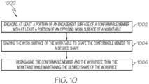
- Fig. 10 shows an example of a method 1000 for preforming the workpiece 602 in slightly different scope.
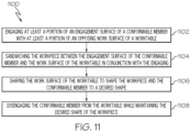
- FIG. 11 shows an example of a method 1100 that engages the conformable member 604 with the work surface 610 upon which the workpiece 602 was prepositioned, sandwiches the workpiece 602 between the conformable member 604 and the work surface 610, shapes the workpiece 602, and disengages from the work surface 610 while retaining the workpiece 602 on the conformable member 604 and maintaining the shape of the conformable member 604 and the workpiece 602.
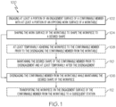
- a method 100 for preforming a workpiece 602 includes engaging 102 at least a portion of an engagement surface 606 of a conformable member 604 with at least a portion of an opposing work surface 610 of a worktable 608.
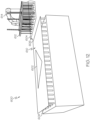
- the workpiece 602 is prepositioned on the work surface 610 (see, e.g., Fig. 12 ) such that the workpiece 602 is compressed between the engagement surface 606 and the work surface 610 in conjunction with the engaging 102.
- the conformable member 604 is disengaged from the worktable 608 while maintaining the desired shape of the workpiece 602 (see, e.g., Fig. 14 ).
- the workpiece 602 is retained on the engagement surface 606 of the conformable member 604 and removed from the work surface 610 of the worktable 608.
- the workpiece 602 may include one or more plies cut from a roll of fabric. As such, the workpiece 602 may initially be relatively flat prior to its shaping.
- the conformable member 604 is a shape retaining component that selectively changes between a more flexible state to a stiffer state. The features of the conformable member 604 are described in more detail below.
- the worktable 608, particularly the work surface 610, is the shaping component that is configured to shape the workpiece 602 and the conformable member 604 based on the desired shape. The features of the worktable 608 are also described in more detail below.
- the worktable 608 may also be referred to as a shape forming table, an adaptive table, an adjustable table or other similarly descriptive names.
- the desired shape includes a three-dimensional shape, a first curved shape, a second curved shape with a double curvature, a third curved shape with two or more curvatures, a two-dimensional shape, or any other suitable shape.
- the method 100 also includes at least temporarily adhering 108 the workpiece 602 to the conformable member 604 prior to the disengaging 106 of the conformable member 604 from the worktable 608.
- the method also includes maintaining 110 the desired shape of the conformable member 604 prior to disengagement and at least temporarily after the disengagement.
- the method 100 also includes transporting 112 the workpiece 602 on the engagement surface 606 of the conformable member 604 from the worktable 608 to a subsequent station.
- the workpiece 602 may be transported to a layup tool for resin infusion.
- the workpiece 602 comprises at least one ply of a reinforcement fabric.
- the reinforcement fabric comprises carbon fibers.
- the reinforcement fabric comprises pre-impregnated fibers.
- the reinforcement fabric may include a dry carbon fabric, a carbon fabric, a graphite fabric, a pre-impregnated fabric, a fiberglass fabric, an aramid fabric, a nylon fabric, or any suitable reinforcement fabric.
- the workpiece 602 comprises a first ply of reinforcement fabric, a second ply of reinforcement fabric, and a thermoplastic veil between the first ply of reinforcement fabric and the second ply of reinforcement fabric.
- the first ply of reinforcement fabric is tack adhered to the second ply of reinforcement fabric.
- the workpiece 602 comprises a first ply of pre-impregnated reinforcement fabric and a second ply of pre-impregnated reinforcement fabric.
- the workpiece 602 is a dry composite material.
- the engaging 102 may include sandwiching 202 the workpiece 602 between the engagement surface 606 of the conformable member 604 and the work surface 610 of the worktable 608 prior to shaping 104 the work surface 610 of the worktable 608 to shape the workpiece 602.
- the shaping 104 the work surface 610 of the worktable 608 may include selectively adjusting 204 at least a portion of the worktable 608 in at least one of a vertical axis and a pitch axis.
- the worktable 608 may include a plurality of actuators arranged in a grid pattern and configured to selectively raise and lower the work surface 610 in the vertical axis to represent curvatures and contours associated with the desired shape for the workpiece 602.
- additional actuators may be used to control the pitch of one or more of the vertical axis actuators to achieve the desired shape.
- the shaping 104 the work surface 610 of the worktable 608 may include selectively moving 206 at least a portion of the worktable 608 to shape the workpiece 602 to at least one interim shaping position.
- the use of multiple shaping position may improve the shaping operation by avoiding wrinkles, bridging, and other defects that can occur in a preformed workpiece.
- the conformable member 604 comprises an electrostatic layer 702.
- at least temporarily adhering 108 the workpiece 602 to the conformable member 604 may include applying 302 an electrostatic charge to the electrostatic layer 702 to at least temporarily adhere the workpiece 602 to the conformable member 604.
- the conformable member 604 comprises a vacuum layer 704.
- at least temporarily adhering 108 the workpiece 602 to the conformable member 604 may include drawing 304 a vacuum on the workpiece 602 from the vacuum layer 704 to at least temporarily adhere the workpiece 602 to the conformable member 604.
- the conformable member 604 comprises a first flexible membrane 802, a conformable core layer 804, and a second flexible membrane 806.
- the first flexible membrane 802 and the second flexible membrane 806 are sealed around a perimeter of the conformable core layer 804.
- maintaining 110 the desired shape of the conformable member 604 may include drawing 402 a vacuum between the first flexible membrane 802 and the second flexible membrane 806 to stiffen the conformable member 604.
- the engaging 102 may include drawing 502 a vacuum between the work surface 610 of the worktable 608 and the engagement surface 606 of the conformable member 604.
- the vacuum may be drawn via at least one of the worktable 608 and the conformable member 604.
- the disengaging 106 of Fig. 1 may include ceasing 504 the vacuum between the work surface 610 of the worktable 608 and the engagement surface 606 of the conformable member 604 to facilitate the disengaging 106 of the conformable member 604 from the worktable 608.
- the engaging 102 may include applying 506 an electromagnetic force to at least one of the work surface 610 of the worktable 608 and the engagement surface 606 of the conformable member 604.
- the electromagnetic force facilitates sandwiching 202 of the workpiece 602 between the engagement surface 606 of the conformable member 604 and the work surface 610 of the worktable 608.
- the disengaging 106 of Fig. 1 may include removing 508 the electromagnetic force to facilitate the disengaging 106 of the conformable member 604 from the worktable 608.
- the engaging 102 may include applying 510 a passive force to at least the conformable member 604.
- the passive force facilitates sandwiching 202 of the workpiece 602 between the engagement surface 606 of the conformable member 604 and the work surface 610 of the worktable 608.
- the disengaging 106 of Fig. 1 may include removing 512 the passive force to facilitate the disengaging 106 of the conformable member 604 from the worktable 608.
- the present disclosure is directed to a system 600 for preforming a workpiece 602.
- the system 600 includes a conformable member 604 with an engagement surface 606 and a worktable 608 with a work surface 610.
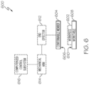
- Fig. 6 shows a functional diagram of these components along with optional end effector 612, mechanical arm 614 and computerized control subsystem 616 components.
- Figs. 7A, 7B , and 8 show functional diagrams of the conformable member 604 and further optional components.
- a system 600 for preforming a workpiece 602 includes a conformable member 604 with an engagement surface 606 and a worktable 608 with a work surface 610.
- the work surface 610 opposing the engagement surface 606.
- the conformable member 604 is configured to engage at least a portion of the engagement surface 606 with at least a portion of the work surface 610 of the worktable 608 to compress the workpiece 602 between the engagement surface 606 and the work surface 610 after the workpiece 602 is prepositioned on the work surface 610 of the worktable 608 (see, e.g., Fig. 12 ).
- the work surface 610 of the worktable 608 is configured to shape the workpiece 602 to a desired shape (see, e.g., Fig. 13 ) while the workpiece 602 is sandwiched between the engagement surface 606 and the work surface 610.
- the conformable member 604 is configured to disengage from the worktable 608 while maintaining engagement with the workpiece 602 and while maintaining the desired shape of the workpiece 602 (see, e.g., Fig. 14 ).
- the system 600 also includes an end effector 612, a mechanical arm 614 and a computerized control subsystem 616.
- the end effector 612 configured to receive the conformable member 604.
- the mechanical arm 614 configured to receive the end effector 612.
- the computerized control subsystem 616 configured to control the mechanical arm 614, the end effector 612, and the conformable member 604 to engage the engagement surface 606 of the conformable member 604 with the work surface 610 of the worktable 608, to disengage the conformable member 604 from the worktable 608, and to transport the workpiece 602 on the engagement surface 606 of the conformable member 604 from the worktable 608 to a subsequent station.
- the end effector 612 may include a pick and place (PnP) end effector suitable for gripping the conformable member 604.
- the system 600 may include a hand-held lifting device to position the conformable member 604 on the worktable 608.
- the hand-held lifting device may be used to remove the conformable member 604 and the workpiece 602 from the worktable 608.
- the hand-held lifting device may be configured to enable multi-person lifting to accommodate safety requirements.
- the conformable member 604 and the worktable 608 are configured to sandwich the workpiece 602 between the engagement surface 606 of the conformable member 604 and the work surface 610 of the worktable 608.
- the worktable 608 is configured to shape the workpiece 602 to the desired shape by selectively adjusting 204 (see Fig. 2 ) at least a portion of the worktable 608 in at least one of a vertical axis and a pitch axis.
- the worktable 608 is configured to selectively move at least a portion of the worktable 608 to shape the workpiece 602 to at least one interim shaping position.
- the worktable 608 is configured to selectively move at least another portion of the worktable 608 to shape the workpiece 602 to a desired shaping position representative of the desired shape.
- the desired shape includes a three-dimensional shape, a first curved shape, a second curved shape with a double curvature, a third curved shape with two or more curvatures, a two-dimensional shape, or any other suitable shape.
- the conformable member 604 is configured to at least temporarily adhere the workpiece 602 to the conformable member 604 prior to disengaging 106 (see Fig. 1 ) from the worktable 608.
- the conformable member 604 is configured to maintain the desired shape prior to disengagement and at least temporarily after the disengagement.
- system 600 is configured to draw a vacuum between the work surface 610 of the worktable 608 and the engagement surface 606 of the conformable member 604.
- at least one of the worktable 608 and the conformable member 604 are configured to draw the vacuum.
- the system 600 is configured to cease the vacuum between the work surface 610 of the worktable 608 and the engagement surface 606 of the conformable member 604 to facilitate disengaging 106 (see Fig. 1 ) of the conformable member 604 from the worktable 608.
- the system 600 is configured to apply an electromagnetic force to at least one of the work surface 610 of the worktable 608 and the engagement surface 606 of the conformable member 604.
- the electromagnetic force facilitates sandwiching 202 (see Fig. 2 ) of the workpiece 602 between the engagement surface 606 of the conformable member 604 and the work surface 610 of the worktable 608.
- the system 600 is configured to remove the electromagnetic force to facilitate disengaging 106 (see Fig. 1 ) of the conformable member 604 from the worktable 608.
- system 600 is configured to apply a passive force to at least the conformable member 604.
- the passive force facilitates sandwiching 202 (see Fig. 2 ) of the workpiece 602 between the engagement surface 606 of the conformable member 604 and the work surface 610 of the worktable 608.
- the system 600 is configured to remove the passive force to facilitate disengaging 106 (see Fig. 1 ) of the conformable member 604 from the worktable 608.
- the conformable member 604 of Fig. 6 may include an electrostatic layer 702.
- the conformable member 604 is configured to apply an electrostatic charge to the electrostatic layer 702 to at least temporarily adhere the workpiece 602 to the conformable member 604.
- the conformable member 604 of Fig. 6 may include a vacuum layer 704.
- the conformable member 604 is configured to draw a vacuum on the workpiece 602 using the vacuum layer 704 to at least temporarily adhere the workpiece 602 to the conformable member 604.
- the conformable member 604 of Fig. 6 may include a first flexible membrane 802, a conformable core layer 804 and a second flexible membrane 806.
- the first flexible membrane 802 and the second flexible membrane 806 are sealed around a perimeter of the conformable core layer (804).
- the conformable member 604 is configured to permit a vacuum to be drawn between the first flexible membrane 802 and the second flexible membrane 806 to stiffen the conformable member 604.
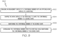
- Fig. 9 shows an example of a method 900 that engages a conformable member 604 with the work surface 610, shapes the conformal member 604, maintains the shape of the conformable member 604, and disengages from the work surface 610 while maintaining the shape of the conformable member 604.
- a composite manufacturing method 900 includes engaging 902 an engagement surface 606 of a conformable member 604 with an opposing work surface 610 of a worktable 608.
- the engagement surface 606 of the conformable member 604 is engaged with the work surface 610 of the worktable 608, shaping 904 the work surface 610 of the worktable 608 to shape the conformable member 604 to a desired shape (see, e.g., Fig. 13 ).
- the conformable member 604 is maintained at the desired shape.
- disengaging 908 the conformable member 604 from the worktable 608 while maintaining 906 the conformable member 604 at the desired shape see, e.g., Fig. 14 ).
- a workpiece 602 is prepositioned on the work surface 610 (see, e.g., Fig. 12 ).
- the workpiece 602 is compressed between the engagement surface 606 of the conformable member 604 and the work surface 610 of the worktable 608.
- the shaping 904 the work surface 610 of the worktable 608 also shapes the workpiece 602 to the desired shape.
- the desired shape of the workpiece 602 is maintained.
- the workpiece 602 is retained on the engagement surface 606 of the conformable member 604 and removed from the work surface 610 of the worktable 608.
- the conformable member 604 comprises a first flexible membrane 802, a conformable core layer 804, and a second flexible membrane 806.
- the first flexible membrane 802 and the second flexible membrane 806 are sealed around a perimeter of the conformable core layer 804.
- maintaining 906 the conformable member 604 at the desired shape may include drawing a vacuum on the conformable member 604 to stiffen the conformable member 604 at the desired shape.
- a method 1000 for preforming a workpiece 602 includes engaging 1002 at least a portion of an engagement surface 606 of a conformable member 604 with at least a portion of an opposing work surface 610 of a worktable 608.
- the workpiece 602 is prepositioned on the work surface 610 (see, e.g., Fig. 12 ) such that the workpiece 602 is compressed between the engagement surface 606 and the work surface 610 in conjunction with the engaging 1002.
- the conformable member 604 and the workpiece 602 are disengaged from the worktable 608 while maintaining the desired shape of the workpiece 602 (see, e.g., Fig. 14 ).
- the workpiece 602 is retained on the engagement surface 606 of the conformable member 604 and removed from the work surface 610 of the worktable 608.
- a method 1100 for preforming a workpiece 602 includes engaging 1102 at least a portion of an engagement surface 606 of a conformable member 604 with at least a portion of an opposing work surface 610 of a worktable 608.
- the workpiece 602 is prepositioned on the work surface 610 (see, e.g., Fig. 12 ).
- the workpiece 602 is sandwiched between the engagement surface 606 of the conformable member 604 and the work surface 610 of the worktable 608 in conjunction with the engaging 1102.
- the conformable member 604 is disengaged from the worktable 608 while maintaining the desired shape of the workpiece 602 (see, e.g., Fig. 14 ).
- the workpiece 602 is retained on the engagement surface 606 of the conformable member 604 and removed from the work surface 610 of the worktable 608.
- Examples of the methods 100, 900, 1000, 1100 and the system 600 may be related to, or used in the context of workpiece (e.g., part) fabrication for aircraft manufacturing.
- workpiece e.g., part
- the examples and principles disclosed herein may be applied to other products in the aerospace industry and other industries, such as the automotive industry, the space industry, the construction industry, and other design and manufacturing industries. Accordingly, in addition to aircraft, the examples and principles disclosed herein may apply to stamp forming workpieces to form an assembly for other types of vehicles (e.g., land vehicles, marine vehicles, space vehicles, etc.), stand-alone structures, high-traffic surfaces, and other high-contact surfaces.
- vehicles e.g., land vehicles, marine vehicles, space vehicles, etc.
- stand-alone structures e.g., high-traffic surfaces, and other high-contact surfaces.
- example means that one or more feature, structure, element, component, characteristic, and/or operational step described in connection with the example is included in at least one aspect, embodiment, and/or implementation of the subject matter according to the present disclosure.
- the phrases “an example,” “another example,” “one or more examples,” and similar language throughout the present disclosure may, but do not necessarily, refer to the same example.
- the subject matter characterizing any one example may, but does not necessarily, include the subject matter characterizing any other example.
- subject matter characterizing any one example may be, but is not necessarily, combined with the subject matter characterizing any other example.
- a system, apparatus, device, structure, article, element, component, or hardware "configured to” perform a specified function is indeed capable of performing the specified function without any alteration, rather than merely having potential to perform the specified function after further modification.
- the system, apparatus, device, structure, article, element, component, or hardware "configured to” perform a specified function is specifically selected, created, implemented, utilized, programmed, and/or designed for the purpose of performing the specified function.
- "configured to” denotes existing characteristics of a system, apparatus, structure, article, element, component, or hardware that enable the system, apparatus, structure, article, element, component, or hardware to perform the specified function without further modification.
- a system, apparatus, device, structure, article, element, component, or hardware described as being “configured to” perform a particular function may additionally or alternatively be described as being “adapted to” and/or as being “operative to” perform that function.
- first,” “second,” “third,” etc. are used herein merely as labels, and are not intended to impose ordinal, positional, or hierarchical requirements on the items to which these terms refer. Moreover, reference to, e.g., a “second” item does not require or preclude the existence of, e.g., a "first” or lower-numbered item, and/or, e.g., a "third” or higher-numbered item.
- the phrase "at least one of,” when used with a list of items, means different combinations of one or more of the listed items may be used and only one of each item in the list may be needed.
- “at least one of item A, item B, and item C” may include, without limitation, item A or item A and item B. This example also may include item A, item B, and item C, or item B and item C.
- "at least one of' may be, for example, without limitation, two of item A, one of item B, and ten of item C; four of item B and seven of item C; and other suitable combinations.
- the term “and/or” and the "/" symbol includes any and all combinations of one or more of the associated listed items.
- Coupled refers to two or more elements that are joined, linked, fastened, attached, connected, put in communication, or otherwise associated (e.g., mechanically, electrically, fluidly, optically, electromagnetically) with one another.
- the elements may be associated directly or indirectly.
- element A may be directly associated with element B.
- element A may be indirectly associated with element B, for example, via another element C. It will be understood that not all associations among the various disclosed elements are necessarily represented. Accordingly, couplings other than those depicted in the figures may also exist.
- the term “approximately” refers to or represents a condition that is close to, but not exactly, the stated condition that still performs the desired function or achieves the desired result.
- the term “approximately” refers to a condition that is within an acceptable predetermined tolerance or accuracy, such as to a condition that is within 10% of the stated condition.
- the term “approximately” does not exclude a condition that is exactly the stated condition.
- the term “substantially” refers to a condition that is essentially the stated condition that performs the desired function or achieves the desired result.
- Figs. 6 , 7A , 7B and 8 may represent functional elements, features, or components thereof and do not necessarily imply any particular structure. Accordingly, modifications, additions and/or omissions may be made to the illustrated structure. Additionally, those skilled in the art will appreciate that not all elements, features, and/or components described and illustrated in Figs. 6 , 7A , 7B and 8 , referred to above, need be included in every example and not all elements, features, and/or components described herein are necessarily depicted in each illustrative example. Accordingly, some of the elements, features, and/or components described and illustrated in Figs.
- Figs. 1-5 and 9-11 referred to above, the blocks may represent operations, steps, and/or portions thereof, and lines connecting the various blocks do not imply any particular order or dependency of the operations or portions thereof. It will be understood that not all dependencies among the various disclosed operations are necessarily represented. Figs. 1-5 and 9-11 and the accompanying disclosure describing the operations of the disclosed methods set forth herein should not be interpreted as necessarily determining a sequence in which the operations are to be performed. Rather, although one illustrative order is indicated, it is to be understood that the sequence of the operations may be modified when appropriate. Accordingly, modifications, additions and/or omissions may be made to the operations illustrated and certain operations may be performed in a different order or simultaneously. Additionally, those skilled in the art will appreciate that not all operations described need be performed.
- references throughout the present specification to features, advantages, or similar language used herein do not imply that all the features and advantages that may be realized with the examples disclosed herein should be, or are in, any single example. Rather, language referring to the features and advantages is understood to mean that a specific feature, advantage, or characteristic described in connection with an example is included in at least one example. Thus, discussion of features, advantages, and similar language used throughout the present disclosure may, but does not necessarily, refer to the same example.
Landscapes
- Engineering & Computer Science (AREA)
- Mechanical Engineering (AREA)
- Chemical & Material Sciences (AREA)
- Composite Materials (AREA)
- Processing And Handling Of Plastics And Other Materials For Molding In General (AREA)
- Blow-Moulding Or Thermoforming Of Plastics Or The Like (AREA)
Abstract
Description
- The present disclosure relates generally to preforming a workpiece to a desired shape and, particularly, to shaping a workpiece disposed between a shaping work surface and a conformable member. Various examples of preforming methods and systems disclose features that facilitate use of the conformable member to transport the shaped workpiece to a subsequent manufacturing station. For example, applications of the disclosed methods and systems to various types of reinforcement fabrics for composite manufacturing are disclosed herein. Applications to various other types of workpieces are also contemplated.
- Existing solutions for preforming workpieces, particularly for preforming lightweight fabrics for composite manufacturing, require bulky and heavy equipment. For example, preforming accuracy is governed by the number of pogos/prongs in an end effector used for the preforming. Actuators in such end effectors are large components that limit fidelity of the equipment. In other words, the quantity of actuators is limited by the size of the actuator while the desired fidelity is based on target contours for the preforming operation. Often the desired fidelity simply cannot be achieved because there is not enough space for the amount of actuators required to properly match the target contours. Thus, workpiece deformation is not accurate and creates problems meeting production requirements.
- Accordingly, those skilled in the art continue with research and development efforts to preform workpieces to desired shapes and improve manufacturing processes.
- Disclosed are examples of a method for preforming a workpiece, a composite manufacturing method and a system associated therewith. The following is a non-exhaustive list of examples, which may or may not be claimed, of the subject matter according to the present disclosure.
- In an example, the disclosed method for preforming a workpiece includes:
- (1) engaging at least a portion of an engagement surface of a conformable member with at least a portion of a work surface of a worktable, wherein the workpiece is prepositioned on the work surface such that the workpiece is compressed between the engagement surface and the work surface in conjunction with the engaging; (2) while the workpiece is sandwiched between the engagement surface of the conformable member and the work surface of the worktable, shaping the work surface of the worktable to shape the workpiece to a desired shape; and
- (3) disengaging the conformable member from the worktable while maintaining the desired shape of the workpiece, wherein the workpiece is retained on the engagement surface of the conformable member and removed from the work surface of the worktable.
- In another example, the disclosed method for preforming a workpiece includes:
- (1) engaging at least a portion of an engagement surface of a conformable member with at least a portion of a work surface of a worktable, wherein the workpiece is prepositioned on the work surface such that the workpiece is compressed between the engagement surface and the work surface in conjunction with the engaging; (2) while the workpiece is sandwiched between the engagement surface of the conformable member and the work surface of the worktable, shaping the work surface of the worktable to shape the conformable member to a desired shape; and
- (3) disengaging the conformable member and the workpiece from the worktable while maintaining the desired shape of the workpiece, wherein the workpiece is retained on the engagement surface of the conformable member and removed from the work surface of the worktable.
- In another example, the disclosed method for preforming a workpiece, includes:
(1) engaging at least a portion of an engagement surface of a conformable member with at least a portion of a work surface of a worktable, wherein the workpiece is prepositioned on the work surface; (2) sandwiching the workpiece between the engagement surface of the conformable member and the work surface of the worktable in conjunction with the engaging; (3) while the workpiece is sandwiched between the engagement surface and the work surface, shaping the work surface of the worktable to shape the workpiece and the conformable member to a desired shape; and (4) disengaging the conformable member from the worktable while maintaining the desired shape of the workpiece, wherein the workpiece is retained on the engagement surface of the conformable member and removed from the work surface of the worktable. - In an example, the disclosed composite manufacturing method includes: (1) engaging an engagement surface of a conformable member with a work surface of a worktable; (2) while the engagement surface of the conformable member is engaged with the work surface of the worktable, shaping the work surface of the worktable to shape the conformable member to a desired shape; (3) maintaining the conformable member at the desired shape; and (4) disengaging the conformable member from the worktable while maintaining the conformable member at the desired shape.
- In an example, the disclosed system for preforming a workpiece includes a conformable member with an engagement surface and a worktable with a work surface opposing the engagement surface. The conformable member is configured to engage at least a portion of the engagement surface with at least a portion of the work surface of the worktable to compress the workpiece between the engagement surface and the work surface after the workpiece is prepositioned on the work surface of the worktable. The work surface of the worktable is configured to shape the workpiece to a desired shape while the workpiece is sandwiched between the engagement surface and the work surface. The conformable member is configured to disengage from the worktable while maintaining engagement with the workpiece and while maintaining the desired shape of the workpiece.
- Other examples of the disclosed methods and system will become apparent from the following detailed description, the accompanying drawings, and the appended claims.
-
-
Fig. 1 is a flow diagram of an example of a method for preforming a workpiece; -
Fig. 2 , in combination withFig. 1 , is a flow diagram of another example of a method for preforming a workpiece; -
Fig. 3 , in combination withFig. 1 , is a flow diagram of yet another example of a method for preforming a workpiece; -
Fig. 4 , in combination withFig. 1 , is a flow diagram of still another example of a method for preforming a workpiece; -
Fig. 5 , in combination withFig. 1 , is a flow diagram of still yet another example of a method for preforming a workpiece; -
Fig. 6 is a schematic of an example of a system for preforming a workpiece, depicted in a functional diagram; -
Figs. 7A and 7B are schematics showing examples of a conformable member shown in the system ofFig. 6 , depicted in functional diagrams; -
Fig. 8 is a schematic showing another example of the conformable member shown in the system ofFig. 6 , depicted in a functional diagram; -
Fig. 9 is a flow diagram of an example of a composite manufacturing method; -
Fig. 10 is a flow diagram of another example of a method for preforming a workpiece; and -
Fig. 11 is a flow diagram of yet another example of a method for preforming a workpiece; -
Fig. 12 is a perspective view of an example of a system for preforming a workpiece showing an initial condition with the workpiece prepositioned; -
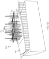
Fig. 13 is another perspective view of the system ofFig. 12 showing the work surface, workpiece, and conforming member in a three-dimensional shape; and -
Fig. 14 is yet another perspective view of the system ofFig. 12 showing the conforming member and workpiece disengaged from the surface of the worktable. - Referring generally to
Figs. 1-6 ,7A ,7B ,8 ,10 and11-14 , by way of examples, the present disclosure is directed to amethod workpiece 602.Figs. 1-5 show examples of amethod 100 that compresses aprepositioned workpiece 602 between aconformable member 604 and awork surface 610, shapes theworkpiece 602, and disengages from thework surface 610 while retaining theworkpiece 602 on theconformable member 604 and maintaining the shape of theworkpiece 602.Fig. 10 shows an example of amethod 1000 for preforming theworkpiece 602 in slightly different scope.Fig. 11 shows an example of amethod 1100 that engages theconformable member 604 with thework surface 610 upon which theworkpiece 602 was prepositioned, sandwiches theworkpiece 602 between theconformable member 604 and thework surface 610, shapes theworkpiece 602, and disengages from thework surface 610 while retaining theworkpiece 602 on theconformable member 604 and maintaining the shape of theconformable member 604 and theworkpiece 602. - With reference again to
Figs. 1 ,6 and12-14 , in one or more examples, amethod 100 for preforming aworkpiece 602 includes engaging 102 at least a portion of anengagement surface 606 of aconformable member 604 with at least a portion of anopposing work surface 610 of aworktable 608. Theworkpiece 602 is prepositioned on the work surface 610 (see, e.g.,Fig. 12 ) such that theworkpiece 602 is compressed between theengagement surface 606 and thework surface 610 in conjunction with the engaging 102. Next, while theworkpiece 602 is sandwiched between theengagement surface 606 of theconformable member 604 and thework surface 610 of theworktable 608, shaping 104 thework surface 610 of theworktable 608 to shape theworkpiece 602 to a desired shape (see, e.g.,Fig. 13 ). At 106, theconformable member 604 is disengaged from theworktable 608 while maintaining the desired shape of the workpiece 602 (see, e.g.,Fig. 14 ). Theworkpiece 602 is retained on theengagement surface 606 of theconformable member 604 and removed from thework surface 610 of theworktable 608. - The
workpiece 602 may include one or more plies cut from a roll of fabric. As such, theworkpiece 602 may initially be relatively flat prior to its shaping. Theconformable member 604 is a shape retaining component that selectively changes between a more flexible state to a stiffer state. The features of theconformable member 604 are described in more detail below. Theworktable 608, particularly thework surface 610, is the shaping component that is configured to shape theworkpiece 602 and theconformable member 604 based on the desired shape. The features of theworktable 608 are also described in more detail below. Theworktable 608 may also be referred to as a shape forming table, an adaptive table, an adjustable table or other similarly descriptive names. - In another example of the
method 100, the desired shape includes a three-dimensional shape, a first curved shape, a second curved shape with a double curvature, a third curved shape with two or more curvatures, a two-dimensional shape, or any other suitable shape. - In yet another example, the
method 100 also includes at least temporarily adhering 108 theworkpiece 602 to theconformable member 604 prior to the disengaging 106 of theconformable member 604 from theworktable 608. - In a further example, the method also includes maintaining 110 the desired shape of the
conformable member 604 prior to disengagement and at least temporarily after the disengagement. - In still another example, the
method 100 also includes transporting 112 theworkpiece 602 on theengagement surface 606 of theconformable member 604 from theworktable 608 to a subsequent station. For example, theworkpiece 602 may be transported to a layup tool for resin infusion. - In still yet another example of the
method 100, theworkpiece 602 comprises at least one ply of a reinforcement fabric. In a further example, the reinforcement fabric comprises carbon fibers. In another further example, the reinforcement fabric comprises pre-impregnated fibers. In other examples, the reinforcement fabric may include a dry carbon fabric, a carbon fabric, a graphite fabric, a pre-impregnated fabric, a fiberglass fabric, an aramid fabric, a nylon fabric, or any suitable reinforcement fabric. - In another example of the
method 100, theworkpiece 602 comprises a first ply of reinforcement fabric, a second ply of reinforcement fabric, and a thermoplastic veil between the first ply of reinforcement fabric and the second ply of reinforcement fabric. In a further embodiment, the first ply of reinforcement fabric is tack adhered to the second ply of reinforcement fabric. - In yet another example of the
method 100, theworkpiece 602 comprises a first ply of pre-impregnated reinforcement fabric and a second ply of pre-impregnated reinforcement fabric. - In still another example of the
method 100, theworkpiece 602 is a dry composite material. - With reference again to
Figs. 1 ,2 and6 , in another example of themethod 100 ofFig. 1 , the engaging 102 may include sandwiching 202 theworkpiece 602 between theengagement surface 606 of theconformable member 604 and thework surface 610 of theworktable 608 prior to shaping 104 thework surface 610 of theworktable 608 to shape theworkpiece 602. - In yet another example of the
method 100 ofFig. 1 , the shaping 104 thework surface 610 of theworktable 608 may include selectively adjusting 204 at least a portion of theworktable 608 in at least one of a vertical axis and a pitch axis. For example, theworktable 608 may include a plurality of actuators arranged in a grid pattern and configured to selectively raise and lower thework surface 610 in the vertical axis to represent curvatures and contours associated with the desired shape for theworkpiece 602. Similarly, additional actuators may be used to control the pitch of one or more of the vertical axis actuators to achieve the desired shape. - In still another example of the
method 100 ofFig. 1 , the shaping 104 thework surface 610 of theworktable 608 may include selectively moving 206 at least a portion of theworktable 608 to shape theworkpiece 602 to at least one interim shaping position. Next, selectively moving 208 at least another portion of theworktable 608 to shape theworkpiece 602 to a desired shaping position representative of the desired shape. The use of multiple shaping position may improve the shaping operation by avoiding wrinkles, bridging, and other defects that can occur in a preformed workpiece. - With reference again to
Figs. 1 ,3 ,6 and7A , in still yet another example of themethod 100 ofFig. 1 , theconformable member 604 comprises anelectrostatic layer 702. In this example, at least temporarily adhering 108 theworkpiece 602 to theconformable member 604 may include applying 302 an electrostatic charge to theelectrostatic layer 702 to at least temporarily adhere theworkpiece 602 to theconformable member 604. - With reference again to
Figs. 1 ,3 ,6 and7B , in another example of themethod 100 ofFig. 1 , theconformable member 604 comprises avacuum layer 704. In this example, at least temporarily adhering 108 theworkpiece 602 to theconformable member 604 may include drawing 304 a vacuum on theworkpiece 602 from thevacuum layer 704 to at least temporarily adhere theworkpiece 602 to theconformable member 604. - With reference again to
Figs. 1 ,4 ,6 and8 , in yet another example of themethod 100 ofFig. 1 , theconformable member 604 comprises a firstflexible membrane 802, aconformable core layer 804, and a secondflexible membrane 806. The firstflexible membrane 802 and the secondflexible membrane 806 are sealed around a perimeter of theconformable core layer 804. In this example, maintaining 110 the desired shape of theconformable member 604 may include drawing 402 a vacuum between the firstflexible membrane 802 and the secondflexible membrane 806 to stiffen theconformable member 604. - With reference again to
Figs. 1 ,5 and6 , in still another example of themethod 100 ofFig. 1 , the engaging 102 may include drawing 502 a vacuum between thework surface 610 of theworktable 608 and theengagement surface 606 of theconformable member 604. In a further example, the vacuum may be drawn via at least one of theworktable 608 and theconformable member 604. In another further example, the disengaging 106 ofFig. 1 may include ceasing 504 the vacuum between thework surface 610 of theworktable 608 and theengagement surface 606 of theconformable member 604 to facilitate the disengaging 106 of theconformable member 604 from theworktable 608. - In still yet another example of the
method 100 ofFig. 1 , the engaging 102 may include applying 506 an electromagnetic force to at least one of thework surface 610 of theworktable 608 and theengagement surface 606 of theconformable member 604. In a further example, the electromagnetic force facilitates sandwiching 202 of theworkpiece 602 between theengagement surface 606 of theconformable member 604 and thework surface 610 of theworktable 608. In another further example, the disengaging 106 ofFig. 1 may include removing 508 the electromagnetic force to facilitate the disengaging 106 of theconformable member 604 from theworktable 608. - In another example of the
method 100 ofFig. 1 , the engaging 102 may include applying 510 a passive force to at least theconformable member 604. In a further example, the passive force facilitates sandwiching 202 of theworkpiece 602 between theengagement surface 606 of theconformable member 604 and thework surface 610 of theworktable 608. In another further example, the disengaging 106 ofFig. 1 may include removing 512 the passive force to facilitate the disengaging 106 of theconformable member 604 from theworktable 608. - Referring generally to
Figs. 6 ,7A ,7B ,8 and12-14 , by way of examples, the present disclosure is directed to asystem 600 for preforming aworkpiece 602. Thesystem 600 includes aconformable member 604 with anengagement surface 606 and aworktable 608 with awork surface 610.Fig. 6 shows a functional diagram of these components along withoptional end effector 612,mechanical arm 614 andcomputerized control subsystem 616 components.Figs. 7A, 7B , and8 , for example, show functional diagrams of theconformable member 604 and further optional components. - With reference again to
Fig. 6 and12-14 , in one or more examples, asystem 600 for preforming aworkpiece 602 includes aconformable member 604 with anengagement surface 606 and aworktable 608 with awork surface 610. Thework surface 610 opposing theengagement surface 606. Theconformable member 604 is configured to engage at least a portion of theengagement surface 606 with at least a portion of thework surface 610 of theworktable 608 to compress theworkpiece 602 between theengagement surface 606 and thework surface 610 after theworkpiece 602 is prepositioned on thework surface 610 of the worktable 608 (see, e.g.,Fig. 12 ). Thework surface 610 of theworktable 608 is configured to shape theworkpiece 602 to a desired shape (see, e.g.,Fig. 13 ) while theworkpiece 602 is sandwiched between theengagement surface 606 and thework surface 610. Theconformable member 604 is configured to disengage from theworktable 608 while maintaining engagement with theworkpiece 602 and while maintaining the desired shape of the workpiece 602 (see, e.g.,Fig. 14 ). - In another example, the
system 600 also includes anend effector 612, amechanical arm 614 and acomputerized control subsystem 616. Theend effector 612 configured to receive theconformable member 604. Themechanical arm 614 configured to receive theend effector 612. Thecomputerized control subsystem 616 configured to control themechanical arm 614, theend effector 612, and theconformable member 604 to engage theengagement surface 606 of theconformable member 604 with thework surface 610 of theworktable 608, to disengage theconformable member 604 from theworktable 608, and to transport theworkpiece 602 on theengagement surface 606 of theconformable member 604 from theworktable 608 to a subsequent station. For example, theend effector 612 may include a pick and place (PnP) end effector suitable for gripping theconformable member 604. - In a more simplified example, the
system 600 may include a hand-held lifting device to position theconformable member 604 on theworktable 608. Similarly, the hand-held lifting device may be used to remove theconformable member 604 and theworkpiece 602 from theworktable 608. The hand-held lifting device may be configured to enable multi-person lifting to accommodate safety requirements. - In yet another example of the
system 600, theconformable member 604 and theworktable 608 are configured to sandwich theworkpiece 602 between theengagement surface 606 of theconformable member 604 and thework surface 610 of theworktable 608. - In still another example of the
system 600, theworktable 608 is configured to shape theworkpiece 602 to the desired shape by selectively adjusting 204 (seeFig. 2 ) at least a portion of theworktable 608 in at least one of a vertical axis and a pitch axis. - In still yet another example of the
system 600, theworktable 608 is configured to selectively move at least a portion of theworktable 608 to shape theworkpiece 602 to at least one interim shaping position. Theworktable 608 is configured to selectively move at least another portion of theworktable 608 to shape theworkpiece 602 to a desired shaping position representative of the desired shape. - In another example of the
system 600, the desired shape includes a three-dimensional shape, a first curved shape, a second curved shape with a double curvature, a third curved shape with two or more curvatures, a two-dimensional shape, or any other suitable shape. - In yet another example of the
system 600, theconformable member 604 is configured to at least temporarily adhere theworkpiece 602 to theconformable member 604 prior to disengaging 106 (seeFig. 1 ) from theworktable 608. In a further example, theconformable member 604 is configured to maintain the desired shape prior to disengagement and at least temporarily after the disengagement. - In still another example, the
system 600 is configured to draw a vacuum between thework surface 610 of theworktable 608 and theengagement surface 606 of theconformable member 604. In a further example, at least one of theworktable 608 and theconformable member 604 are configured to draw the vacuum. In another further example, thesystem 600 is configured to cease the vacuum between thework surface 610 of theworktable 608 and theengagement surface 606 of theconformable member 604 to facilitate disengaging 106 (seeFig. 1 ) of theconformable member 604 from theworktable 608. - In still yet another example, the
system 600 is configured to apply an electromagnetic force to at least one of thework surface 610 of theworktable 608 and theengagement surface 606 of theconformable member 604. In a further example, the electromagnetic force facilitates sandwiching 202 (seeFig. 2 ) of theworkpiece 602 between theengagement surface 606 of theconformable member 604 and thework surface 610 of theworktable 608. In another further example, thesystem 600 is configured to remove the electromagnetic force to facilitate disengaging 106 (seeFig. 1 ) of theconformable member 604 from theworktable 608. - In another example, the
system 600 is configured to apply a passive force to at least theconformable member 604. In a further example, the passive force facilitates sandwiching 202 (seeFig. 2 ) of theworkpiece 602 between theengagement surface 606 of theconformable member 604 and thework surface 610 of theworktable 608. In another further example, thesystem 600 is configured to remove the passive force to facilitate disengaging 106 (seeFig. 1 ) of theconformable member 604 from theworktable 608. - With reference again to
Figs. 6 and7 , in one or more examples, theconformable member 604 ofFig. 6 may include anelectrostatic layer 702. In this example, theconformable member 604 is configured to apply an electrostatic charge to theelectrostatic layer 702 to at least temporarily adhere theworkpiece 602 to theconformable member 604. - In another example, the
conformable member 604 ofFig. 6 may include avacuum layer 704. In this example, theconformable member 604 is configured to draw a vacuum on theworkpiece 602 using thevacuum layer 704 to at least temporarily adhere theworkpiece 602 to theconformable member 604. - With reference again to
Figs. 6 and8 , in one or more examples, theconformable member 604 ofFig. 6 may include a firstflexible membrane 802, aconformable core layer 804 and a secondflexible membrane 806. The firstflexible membrane 802 and the secondflexible membrane 806 are sealed around a perimeter of the conformable core layer (804). In this example, theconformable member 604 is configured to permit a vacuum to be drawn between the firstflexible membrane 802 and the secondflexible membrane 806 to stiffen theconformable member 604. - Referring generally to
Figs. 6 ,8 ,9 and12-14 , by way of examples, the present disclosure is directed to acomposite manufacturing method 900.Fig. 9 shows an example of amethod 900 that engages aconformable member 604 with thework surface 610, shapes theconformal member 604, maintains the shape of theconformable member 604, and disengages from thework surface 610 while maintaining the shape of theconformable member 604. - With reference again to
Figs. 6 ,9 and12-14 , in one or more examples, acomposite manufacturing method 900 includes engaging 902 anengagement surface 606 of aconformable member 604 with an opposingwork surface 610 of aworktable 608. Next, while theengagement surface 606 of theconformable member 604 is engaged with thework surface 610 of theworktable 608, shaping 904 thework surface 610 of theworktable 608 to shape theconformable member 604 to a desired shape (see, e.g.,Fig. 13 ). At 906, theconformable member 604 is maintained at the desired shape. Next, disengaging 908 theconformable member 604 from theworktable 608 while maintaining 906 theconformable member 604 at the desired shape (see, e.g.,Fig. 14 ). - In another example of the
method 900, aworkpiece 602 is prepositioned on the work surface 610 (see, e.g.,Fig. 12 ). In this example, theworkpiece 602 is compressed between theengagement surface 606 of theconformable member 604 and thework surface 610 of theworktable 608. The shaping 904 thework surface 610 of theworktable 608 also shapes theworkpiece 602 to the desired shape. The desired shape of theworkpiece 602 is maintained. Theworkpiece 602 is retained on theengagement surface 606 of theconformable member 604 and removed from thework surface 610 of theworktable 608. - With reference again to
Figs. 6 ,8 , and9 , in one or more examples of themethod 900, theconformable member 604 comprises a firstflexible membrane 802, aconformable core layer 804, and a secondflexible membrane 806. The firstflexible membrane 802 and the secondflexible membrane 806 are sealed around a perimeter of theconformable core layer 804. In this example, maintaining 906 theconformable member 604 at the desired shape may include drawing a vacuum on theconformable member 604 to stiffen theconformable member 604 at the desired shape. - With reference again to
Figs. 6 ,10 and12-14 , in one or more examples, amethod 1000 for preforming aworkpiece 602 includes engaging 1002 at least a portion of anengagement surface 606 of aconformable member 604 with at least a portion of an opposingwork surface 610 of aworktable 608. Theworkpiece 602 is prepositioned on the work surface 610 (see, e.g.,Fig. 12 ) such that theworkpiece 602 is compressed between theengagement surface 606 and thework surface 610 in conjunction with the engaging 1002. Next, while theworkpiece 602 is sandwiched between theengagement surface 606 of theconformable member 604 and thework surface 610 of theworktable 608, shaping 1004 thework surface 610 of theworktable 608 to shape theconformable member 604 to a desired shape (see, e.g.,Fig. 13 ). At 1006, theconformable member 604 and theworkpiece 602 are disengaged from theworktable 608 while maintaining the desired shape of the workpiece 602 (see, e.g.,Fig. 14 ). Theworkpiece 602 is retained on theengagement surface 606 of theconformable member 604 and removed from thework surface 610 of theworktable 608. - With reference again to
Figs. 6 and11-14 , in one or more examples, amethod 1100 for preforming aworkpiece 602 includes engaging 1102 at least a portion of anengagement surface 606 of aconformable member 604 with at least a portion of an opposingwork surface 610 of aworktable 608. Theworkpiece 602 is prepositioned on the work surface 610 (see, e.g.,Fig. 12 ). At 1104, theworkpiece 602 is sandwiched between theengagement surface 606 of theconformable member 604 and thework surface 610 of theworktable 608 in conjunction with the engaging 1102. Next, while theworkpiece 602 is sandwiched between theengagement surface 606 and thework surface 610, shaping 1106 thework surface 610 of theworktable 608 to shape theworkpiece 602 and theconformable member 604 to a desired shape (see, e.g.,Fig. 13 ). At 1108, theconformable member 604 is disengaged from theworktable 608 while maintaining the desired shape of the workpiece 602 (see, e.g.,Fig. 14 ). Theworkpiece 602 is retained on theengagement surface 606 of theconformable member 604 and removed from thework surface 610 of theworktable 608. - Examples of the
methods system 600 may be related to, or used in the context of workpiece (e.g., part) fabrication for aircraft manufacturing. Although an aircraft example is described, the examples and principles disclosed herein may be applied to other products in the aerospace industry and other industries, such as the automotive industry, the space industry, the construction industry, and other design and manufacturing industries. Accordingly, in addition to aircraft, the examples and principles disclosed herein may apply to stamp forming workpieces to form an assembly for other types of vehicles (e.g., land vehicles, marine vehicles, space vehicles, etc.), stand-alone structures, high-traffic surfaces, and other high-contact surfaces. - The preceding detailed description refers to the accompanying drawings, which illustrate specific examples described by the present disclosure. Other examples having different structures and operations do not depart from the scope of the present disclosure. Like reference numerals may refer to the same feature, element, or component in the different drawings. Throughout the present disclosure, any one of a plurality of items may be referred to individually as the item and a plurality of items may be referred to collectively as the items and may be referred to with like reference numerals. Moreover, as used herein, a feature, element, component, or step preceded with the word "a" or "an" should be understood as not excluding a plurality of features, elements, components, or steps, unless such exclusion is explicitly recited.
- Illustrative, non-exhaustive examples, which may be, but are not necessarily, claimed, of the subject matter according to the present disclosure are provided above. Reference herein to "example" means that one or more feature, structure, element, component, characteristic, and/or operational step described in connection with the example is included in at least one aspect, embodiment, and/or implementation of the subject matter according to the present disclosure. Thus, the phrases "an example," "another example," "one or more examples," and similar language throughout the present disclosure may, but do not necessarily, refer to the same example. Further, the subject matter characterizing any one example may, but does not necessarily, include the subject matter characterizing any other example. Moreover, the subject matter characterizing any one example may be, but is not necessarily, combined with the subject matter characterizing any other example.
- As used herein, a system, apparatus, device, structure, article, element, component, or hardware "configured to" perform a specified function is indeed capable of performing the specified function without any alteration, rather than merely having potential to perform the specified function after further modification. In other words, the system, apparatus, device, structure, article, element, component, or hardware "configured to" perform a specified function is specifically selected, created, implemented, utilized, programmed, and/or designed for the purpose of performing the specified function. As used herein, "configured to" denotes existing characteristics of a system, apparatus, structure, article, element, component, or hardware that enable the system, apparatus, structure, article, element, component, or hardware to perform the specified function without further modification. For purposes of this disclosure, a system, apparatus, device, structure, article, element, component, or hardware described as being "configured to" perform a particular function may additionally or alternatively be described as being "adapted to" and/or as being "operative to" perform that function.
- Unless otherwise indicated, the terms "first," "second," "third," etc. are used herein merely as labels, and are not intended to impose ordinal, positional, or hierarchical requirements on the items to which these terms refer. Moreover, reference to, e.g., a "second" item does not require or preclude the existence of, e.g., a "first" or lower-numbered item, and/or, e.g., a "third" or higher-numbered item.
- As used herein, the phrase "at least one of," when used with a list of items, means different combinations of one or more of the listed items may be used and only one of each item in the list may be needed. For example, "at least one of item A, item B, and item C" may include, without limitation, item A or item A and item B. This example also may include item A, item B, and item C, or item B and item C. In other examples, "at least one of' may be, for example, without limitation, two of item A, one of item B, and ten of item C; four of item B and seven of item C; and other suitable combinations. As used herein, the term "and/or" and the "/" symbol includes any and all combinations of one or more of the associated listed items.
- For the purpose of this disclosure, the terms "coupled," "coupling," and similar terms refer to two or more elements that are joined, linked, fastened, attached, connected, put in communication, or otherwise associated (e.g., mechanically, electrically, fluidly, optically, electromagnetically) with one another. In various examples, the elements may be associated directly or indirectly. As an example, element A may be directly associated with element B. As another example, element A may be indirectly associated with element B, for example, via another element C. It will be understood that not all associations among the various disclosed elements are necessarily represented. Accordingly, couplings other than those depicted in the figures may also exist.
- As used herein, the term "approximately" refers to or represents a condition that is close to, but not exactly, the stated condition that still performs the desired function or achieves the desired result. As an example, the term "approximately" refers to a condition that is within an acceptable predetermined tolerance or accuracy, such as to a condition that is within 10% of the stated condition. However, the term "approximately" does not exclude a condition that is exactly the stated condition. As used herein, the term "substantially" refers to a condition that is essentially the stated condition that performs the desired function or achieves the desired result.
-
Figs. 6 ,7A ,7B and8 , referred to above, may represent functional elements, features, or components thereof and do not necessarily imply any particular structure. Accordingly, modifications, additions and/or omissions may be made to the illustrated structure. Additionally, those skilled in the art will appreciate that not all elements, features, and/or components described and illustrated inFigs. 6 ,7A ,7B and8 , referred to above, need be included in every example and not all elements, features, and/or components described herein are necessarily depicted in each illustrative example. Accordingly, some of the elements, features, and/or components described and illustrated inFigs. 6 ,7A ,7B and8 may be combined in various ways without the need to include other features described and illustrated inFigs. 6 ,7A ,7B and8 , other drawing figures, and/or the accompanying disclosure, even though such combination or combinations are not explicitly illustrated herein. Similarly, additional features not limited to the examples presented, may be combined with some or all the features shown and described herein. Unless otherwise explicitly stated, the schematic illustrations of the examples depicted inFigs. 6 ,7A ,7B and8 , referred to above, are not meant to imply structural limitations with respect to the illustrative example. Rather, although one illustrative structure is indicated, it is to be understood that the structure may be modified when appropriate. Accordingly, modifications, additions and/or omissions may be made to the illustrated structure. Furthermore, elements, features, and/or components that serve a similar, or at least substantially similar, purpose are labeled with like numbers in each ofFigs. 6 ,7A ,7B and8 , and such elements, features, and/or components may not be discussed in detail herein with reference to each ofFigs. 6 ,7A ,7B and8 . Similarly, all elements, features, and/or components may not be labeled in each ofFigs. 6 ,7A ,7B and8 , but reference numerals associated therewith may be utilized herein for consistency. - In
Figs. 1-5 and9-11 , referred to above, the blocks may represent operations, steps, and/or portions thereof, and lines connecting the various blocks do not imply any particular order or dependency of the operations or portions thereof. It will be understood that not all dependencies among the various disclosed operations are necessarily represented.Figs. 1-5 and 9-11 and the accompanying disclosure describing the operations of the disclosed methods set forth herein should not be interpreted as necessarily determining a sequence in which the operations are to be performed. Rather, although one illustrative order is indicated, it is to be understood that the sequence of the operations may be modified when appropriate. Accordingly, modifications, additions and/or omissions may be made to the operations illustrated and certain operations may be performed in a different order or simultaneously. Additionally, those skilled in the art will appreciate that not all operations described need be performed. - Further, the disclosure comprises examples, which are intended to aid in understanding the present invention, according to the following clauses:
- Clause 1. A method for preforming a workpiece, the method comprising:
- engaging at least a portion of an engagement surface of a conformable member with at least a portion of a work surface of a worktable, wherein the workpiece is prepositioned on the work surface such that the workpiece is compressed between the engagement surface and the work surface in conjunction with the engaging;
- while the workpiece is sandwiched between the engagement surface of the conformable member and the work surface of the worktable, shaping the work surface of the worktable to shape the workpiece to a desired shape; and
- disengaging the conformable member from the worktable while maintaining the desired shape of the workpiece, wherein the workpiece is retained on the engagement surface of the conformable member and removed from the work surface of the worktable.
- Clause 2. The method of Clause 1, wherein engaging comprises:
sandwiching the workpiece between the engagement surface of the conformable member and the work surface of the worktable prior to shaping the work surface of the worktable to shape the workpiece. - Clause 3. The method of Clause 1 or 2, wherein shaping the work surface of the worktable comprises:
selectively adjusting at least a portion of the worktable in at least one of a vertical axis and a pitch axis. - Clause 4. The method of any of Clauses 1-3, wherein shaping the work surface of the worktable comprises:
- selectively moving at least a portion of the worktable to shape the workpiece to at least one interim shaping position; and
- selectively moving at least another portion of the worktable to shape the workpiece to a desired shaping position representative of the desired shape.
- Clause 5. The method of any of Clauses 1-4, wherein the desired shape includes at least one of a three-dimensional shape, a first curved shape, a second curved shape with a double curvature, a third curved shape with two or more curvatures, and a two-dimensional shape.
- Clause 6. The method of any of Clauses 1-5, further comprising:
at least temporarily adhering the workpiece to the conformable member prior to the disengaging of the conformable member from the worktable. - Clause 7. The method of Clause 6, wherein the conformable member comprises an electrostatic layer, and wherein at least temporarily adhering the workpiece to the conformable member comprises:
applying an electrostatic charge to the electrostatic layer to at least temporarily adhere the workpiece to the conformable member. - Clause 8. The method of Claim 6 or 7, wherein the conformable member comprises a vacuum layer, and wherein at least temporarily adhering the workpiece to the conformable member comprises:
drawing a vacuum on the workpiece from the vacuum layer to at least temporarily adhere the workpiece to the conformable member. - Clause 9. The method of any of Clauses 6-8, further comprising:
maintaining the desired shape of the conformable member prior to disengagement and at least temporarily after the disengagement. - Clause 10. The method of Clause 9, wherein the conformable member comprises a first flexible membrane, a conformable core layer, and a second flexible membrane, wherein the first flexible membrane and the second flexible membrane are sealed around a perimeter of the conformable core layer, and wherein maintaining the desired shape of the conformable member comprises:
drawing a vacuum between the first flexible membrane and the second flexible membrane to stiffen the conformable member. - Clause 11. The method of any of Clauses 1-10, wherein the engaging comprises:
drawing a vacuum between the work surface of the worktable and the engagement surface of the conformable member. - Clause 12. The method of Clause 11, wherein the vacuum is drawn via at least one of the worktable and the conformable member.
- Clause 13. The method of Clause 11 or 12, wherein the disengaging comprises:
ceasing the vacuum between the work surface of the worktable and the engagement surface of the conformable member to facilitate the disengaging of the conformable member from the worktable. - Clause 14. The method of any of Clauses 1-13, wherein the engaging comprises:
applying an electromagnetic force to at least one of the work surface of the worktable and the engagement surface of the conformable member. - Clause 15. The method of Clause 14, wherein the electromagnetic force facilitates sandwiching of the workpiece between the engagement surface of the conformable member and the work surface of the worktable.
- Clause 16. The method of Clause 14 or 15, wherein the disengaging comprises:
removing the electromagnetic force to facilitate the disengaging of the conformable member from the worktable. - Clause 17. The method of any of Clauses 1-16, wherein the engaging comprises:
applying a passive force to at least the conformable member. - Clause 18. The method of Clause 17, wherein the passive force facilitates sandwiching of the workpiece between the engagement surface of the conformable member and the work surface of the worktable.
- Clause 19. The method of Clause 17 or 18, wherein the disengaging comprises:
removing the passive force to facilitate the disengaging of the conformable member from the worktable. - Clause 20. The method of any of Clauses 1-19, further comprising:
transporting the workpiece on the engagement surface of the conformable member from the worktable to a subsequent station. - Clause 21. The method of any of Clauses 1-20, wherein the workpiece comprises at least one ply of a reinforcement fabric.
- Clause 22. The method of Clause 21, wherein the reinforcement fabric comprises carbon fibers.
- Clause 23. The method of Clause 21 or 22, wherein the reinforcement fabric comprises pre-impregnated fibers.
- Clause 24. The method of any of Clauses 1-23, wherein the workpiece comprises a first ply of reinforcement fabric, a second ply of reinforcement fabric, and a thermoplastic veil between the first ply of reinforcement fabric and the second ply of reinforcement fabric.
- Clause 25. The method of Clause 24, wherein the first ply of reinforcement fabric is tack adhered to the second ply of reinforcement fabric.
- Clause 26. The method of any of Clauses 1-25, wherein the workpiece comprises a first ply of pre-impregnated reinforcement fabric and a second ply of pre-impregnated reinforcement fabric.
- Clause 27. The method of any of Clauses 1-26, wherein the workpiece is a dry composite material.
- Clause 28. A system for preforming a workpiece, the system comprising:
- a conformable member with an engagement surface; and
- a worktable with a work surface opposing the engagement surface,
- wherein the conformable member is configured to engage at least a portion of the engagement surface with at least a portion of the work surface of the worktable to compress the workpiece between the engagement surface and the work surface after the workpiece is prepositioned on the work surface of the worktable,
- wherein the work surface of the worktable is configured to shape the workpiece to a desired shape while the workpiece is sandwiched between the engagement surface and the work surface, and
- wherein the conformable member is configured to disengage from the worktable while maintaining engagement with the workpiece and while maintaining the desired shape of the workpiece.
- Clause 29. The system of Clause 28, further comprising:
- an end effector configured to receive the conformable member;
- a mechanical arm configured to receive the end effector; and
- a computerized control subsystem configured to control the mechanical arm, the end effector, and the conformable member to engage the engagement surface of the conformable member with the work surface of the worktable, to disengage the conformable member from the worktable, and to transport the workpiece on the engagement surface of the conformable member from the worktable to a subsequent station.
- Clause 30. The system of Clause 28 or 29, wherein the conformable member and the worktable are configured to sandwich the workpiece between the engagement surface of the conformable member and the work surface of the worktable.
- Clause 31. The system of any of Clauses 28-30, wherein the worktable is configured to shape the workpiece to the desired shape by selectively adjusting at least a portion of the worktable in at least one of a vertical axis and a pitch axis.
- Clause 32. The system of any of Clauses 28-31, wherein the worktable is configured to selectively move at least a portion of the worktable to shape the workpiece to at least one interim shaping position, wherein the worktable is configured to selectively move at least another portion of the worktable to shape the workpiece to a desired shaping position representative of the desired shape.
- Clause 33. The system of any of Clauses 28-32, wherein the desired shape includes at least one of a three-dimensional shape, a first curved shape, a second curved shape with a double curvature, a third curved shape with two or more curvatures, and a two-dimensional shape.
- Clause 34. The system of any of Clauses 28-33, wherein the conformable member is configured to at least temporarily adhere the workpiece to the conformable member prior to disengaging from the worktable.
- Clause 35. The system of Clause 34, the conformable member comprising:
- an electrostatic layer,
- wherein the conformable member is configured to apply an electrostatic charge to the electrostatic layer to at least temporarily adhere the workpiece to the conformable member.
- Clause 36. The system of Clause 34 or 35, the conformable member comprising:
- a vacuum layer,
- wherein the conformable member is configured to draw a vacuum on the workpiece using the vacuum layer to at least temporarily adhere the workpiece to the conformable member.
- Clause 37. The system of any of Clauses 34-36, wherein the conformable member is configured to maintain the desired shape prior to disengagement and at least temporarily after the disengagement.
- Clause 38. The system of Clause 37, the conformable member comprising:
- a first flexible membrane;
- a conformable core layer; and
- a second flexible membrane,
- wherein the first flexible membrane and the second flexible membrane are sealed around a perimeter of the conformable core layer, and
- wherein the conformable member is configured to permit a vacuum to be drawn between the first flexible membrane and the second flexible membrane to stiffen the conformable member.
- Clause 39. The system of any of Clauses 28-38, wherein the system is configured to draw a vacuum between the work surface of the worktable and the engagement surface of the conformable member.
- Clause 40. The system of Clause 39, wherein at least one of the worktable and the conformable member are configured to draw the vacuum.
- Clause 41. The system of Clause 39 or 40, wherein the system is configured to cease the vacuum between the work surface of the worktable and the engagement surface of the conformable member to facilitate disengaging of the conformable member from the worktable.
- Clause 42. The system of any of Clauses 28-41, wherein the system is configured to apply an electromagnetic force to at least one of the work surface of the worktable and the engagement surface of the conformable member.
- Clause 43. The system of Clause 42, wherein the electromagnetic force facilitates sandwiching of the workpiece between the engagement surface of the conformable member and the work surface of the worktable.
- Clause 44. The system of Clause 42 or 43, wherein the system is configured to remove the electromagnetic force to facilitate disengaging of the conformable member from the worktable.
- Clause 45. The system of any of Clauses 28-44, wherein the system is configured to apply a passive force to at least the conformable member.
- Clause 46. The system of Clause 45, wherein the passive force facilitates sandwiching of the workpiece between the engagement surface of the conformable member and the work surface of the worktable.
- Clause 47. The system of Clause 45 or 46, wherein the system is configured to remove the passive force to facilitate disengaging of the conformable member from the worktable.
- Clause 48. A composite manufacturing method comprising:
- engaging an engagement surface of a conformable member with a work surface of a worktable;
- while the engagement surface of the conformable member is engaged with the work surface of the worktable, shaping the work surface of the worktable to shape the conformable member to a desired shape;
- maintaining the conformable member at the desired shape; and
- disengaging the conformable member from the worktable while maintaining the conformable member at the desired shape.
- Clause 49. The method of Clause 48, wherein the conformable member comprises a first flexible membrane, a conformable core layer, and a second flexible membrane, wherein the first flexible membrane and the second flexible membrane are sealed around a perimeter of the conformable core layer, maintaining the conformable member at the desired shape comprising:
drawing a vacuum on the conformable member to stiffen the conformable member at the desired shape. - Clause 50. The method of Clause 48 or 49, wherein a workpiece is prepositioned on the work surface, wherein the workpiece is compressed between the engagement surface of the conformable member and the work surface of the worktable, wherein the shaping the work surface of the worktable also shapes the workpiece to the desired shape, wherein the desired shape of the workpiece is maintained, wherein the workpiece is retained on the engagement surface of the conformable member and removed from the work surface of the worktable.
- Clause 51. A method for preforming a workpiece, the method comprising:
- engaging at least a portion of an engagement surface of a conformable member with at least a portion of a work surface of a worktable, wherein the workpiece is prepositioned on the work surface such that the workpiece is compressed between the engagement surface and the work surface in conjunction with the engaging;
- while the workpiece is sandwiched between the engagement surface of the conformable member and the work surface of the worktable, shaping the work surface of the worktable to shape the conformable member to a desired shape; and
- disengaging the conformable member and the workpiece from the worktable while maintaining the desired shape of the workpiece, wherein the workpiece is retained on the engagement surface of the conformable member and removed from the work surface of the worktable.
- Clause 52. A method for preforming a workpiece, the method comprising:
- engaging at least a portion of an engagement surface of a conformable member with at least a portion of a work surface of a worktable, wherein the workpiece is prepositioned on the work surface;
- sandwiching the workpiece between the engagement surface of the conformable member and the work surface of the worktable in conjunction with the engaging;
- while the workpiece is sandwiched between the engagement surface and the work surface, shaping the work surface of the worktable to shape the workpiece and the conformable member to a desired shape; and
- disengaging the conformable member from the worktable while maintaining the desired shape of the workpiece, wherein the workpiece is retained on the engagement surface of the conformable member and removed from the work surface of the worktable.
- Further, references throughout the present specification to features, advantages, or similar language used herein do not imply that all the features and advantages that may be realized with the examples disclosed herein should be, or are in, any single example. Rather, language referring to the features and advantages is understood to mean that a specific feature, advantage, or characteristic described in connection with an example is included in at least one example. Thus, discussion of features, advantages, and similar language used throughout the present disclosure may, but does not necessarily, refer to the same example.
- The described features, advantages, and characteristics of one example may be combined in any suitable manner in one or more other examples. One skilled in the relevant art will recognize that the examples described herein may be practiced without one or more of the specific features or advantages of a particular example. In other instances, additional features and advantages may be recognized in certain examples that may not be present in all examples. Furthermore, although various examples of the
methods system 600 have been shown and described, modifications may occur to those skilled in the art upon reading the specification. The present application includes such modifications and is limited only by the scope of the claims.
Claims (15)
- A method (100) for preforming a workpiece, the method (602) comprising:engaging (102) at least a portion of an engagement surface (606) of a conformable member (604) with at least a portion of a work surface (610) of a worktable (608), wherein the workpiece (602), which preferably is dry composite material, is prepositioned on the work surface (610) such that the workpiece (602) is compressed between the engagement surface (606) and the work surface (610) in conjunction with the engaging (102);while the workpiece (602) is sandwiched between the engagement surface (606) of the conformable member (604) and the work surface (610) of the worktable (608), shaping (104) the work surface (610) of the worktable (608) to shape the workpiece (602) to a desired shape; anddisengaging (106) the conformable member (604) from the worktable (608) while maintaining the desired shape of the workpiece (602), wherein the workpiece (602) is retained on the engagement surface (606) of the conformable member (604) and removed from the work surface (610) of the worktable (608).
- The method of Claim 1, wherein engaging (102) comprises:
sandwiching (202) the workpiece (602) between the engagement surface (606) of the conformable member (604) and the work surface (610) of the worktable (608) prior to shaping (104) the work surface (610) of the worktable (608) to shape the workpiece (602). - The method of Claim 1 or 2, wherein shaping (104) the work surface (610) of the worktable (608) comprises:
selectively adjusting (204) at least a portion of the worktable (608) in at least one of a vertical axis and a pitch axis. - The method of any of Claims 1-3, wherein shaping (104) the work surface (610) of the worktable (608) comprises:selectively moving (206) at least a portion of the worktable (608) to shape the workpiece (602) to at least one interim shaping position; andselectively moving (208) at least another portion of the worktable (608) to shape the workpiece (602) to a desired shaping position representative of the desired shape.
- The method of any of Claims 1-4, wherein the desired shape includes at least one of a three-dimensional shape, a first curved shape, a second curved shape with a double curvature, a third curved shape with two or more curvatures, and a two-dimensional shape.
- The method of any of Claims 1-5, further comprising:at least temporarily adhering (108) the workpiece (602) to the conformable member (604) prior to the disengaging (106) of the conformable member (604) from the worktable (608),wherein preferably the conformable member (604) comprises an electrostatic layer (702), and wherein preferably at least temporarily adhering (108) the workpiece (602) to the conformable member (604) comprises:applying (302) an electrostatic charge to the electrostatic layer (702) to at least temporarily adhere the workpiece (602) to the conformable member (604),wherein preferably the conformable member (604) comprises a vacuum layer (704), and wherein preferably at least temporarily adhering (108) the workpiece (602) to the conformable member (604) comprises:
drawing (304) a vacuum on the workpiece (602) from the vacuum layer (704) to at least temporarily adhere the workpiece (602) to the conformable member (604). - The method of Claim 6, further comprising:maintaining (110) the desired shape of the conformable member (604) prior to disengagement and at least temporarily after the disengagement,wherein preferably the conformable member (604) comprises a first flexible membrane (802), a conformable core layer (804), and a second flexible membrane (806), wherein the first flexible membrane (802) and the second flexible membrane (806) are sealed around a perimeter of the conformable core layer (804), and wherein maintaining (110) the desired shape of the conformable member (604) preferably comprises:
drawing (402) a vacuum between the first flexible membrane (802) and the second flexible membrane (806) to stiffen the conformable member (604). - The method of any of Claims 1-7, wherein the engaging (102) comprises:drawing (502) a vacuum between the work surface (610) of the worktable (608) and the engagement surface (606) of the conformable member (604),wherein preferably the vacuum is drawn via at least one of the worktable (608) and the conformable member (604); and/orwherein the disengaging (106) preferably comprises:
ceasing (504) the vacuum between the work surface (610) of the worktable (608) and the engagement surface (606) of the conformable member (604) to facilitate the disengaging (106) of the conformable member (604) from the worktable (608). - The method of any of Claims 1-8, wherein the engaging (102) comprises:applying (506) an electromagnetic force to at least one of the work surface (610) of the worktable (608) and the engagement surface (606) of the conformable member (604),wherein preferably the electromagnetic force facilitates sandwiching (202) of the workpiece (602) between the engagement surface (606) of the conformable member (604) and the work surface (610) of the worktable (608); and/or wherein the disengaging (106) preferably comprises:
removing (508) the electromagnetic force to facilitate the disengaging (106) of the conformable member (604) from the worktable (608). - The method of any pf Claims 1-9, wherein the engaging (102) comprises:applying (510) a passive force to at least the conformable member (604);wherein preferably the passive force facilitates sandwiching (202) of the workpiece (602) between the engagement surface (606) of the conformable member (604) and the work surface (610) of the worktable (608); and/or wherein the disengaging (106) preferably comprises:
removing (512) the passive force to facilitate the disengaging (106) of the conformable member (604) from the worktable (608). - The method of any of Claims 1-10, further comprising:
transporting (112) the workpiece (602) on the engagement surface (606) of the conformable member (604) from the worktable (608) to a subsequent station. - The method of any of Claims 1-11, wherein the workpiece (602) comprises at least one ply of a reinforcement fabric; wherein preferably the reinforcement fabric comprises carbon fibers, or wherein the reinforcement fabric comprises pre-impregnated fibers.
- The method of any of Claims 1-12, wherein the workpiece (602) comprises a first ply of reinforcement fabric, a second ply of reinforcement fabric, and a thermoplastic veil between the first ply of reinforcement fabric and the second ply of reinforcement fabric; wherein the first ply of reinforcement fabric preferably is tack adhered to the second ply of reinforcement fabric.
- The method of any of Claims 1-13, wherein the workpiece (602) comprises a first ply of pre-impregnated reinforcement fabric and a second ply of pre-impregnated reinforcement fabric.
- A system (600) for preforming a workpiece (602), the system comprising:a conformable member (604) with an engagement surface (606); anda worktable (608) with a work surface (610) opposing the engagement surface (606),wherein the conformable member (604) is configured to engage at least a portion of the engagement surface (606) with at least a portion of the work surface (610) of the worktable (608) to compress the workpiece (602) between the engagement surface (606) and the work surface (610) after the workpiece (602) is prepositioned on the work surface (610) of the worktable (608),wherein the work surface (610) of the worktable (608) is configured to shape the workpiece (602) to a desired shape while the workpiece (602) is sandwiched between the engagement surface (606) and the work surface (610), andwherein the conformable member (604) is configured to disengage from the worktable (608) while maintaining engagement with the workpiece (602) and while maintaining the desired shape of the workpiece (602).
Applications Claiming Priority (1)
| Application Number | Priority Date | Filing Date | Title |
|---|---|---|---|
| US18/161,170 US12611824B2 (en) | 2023-01-30 | 2023-01-30 | Method for preforming a workpiece, composite manufacturing method and system associated therewith |
Publications (2)
| Publication Number | Publication Date |
|---|---|
| EP4406717A1 true EP4406717A1 (en) | 2024-07-31 |
| EP4406717B1 EP4406717B1 (en) | 2025-10-29 |
Family
ID=88833864
Family Applications (1)
| Application Number | Title | Priority Date | Filing Date |
|---|---|---|---|
| EP23209353.4A Active EP4406717B1 (en) | 2023-01-30 | 2023-11-13 | Method for preforming a workpiece, composite manufacturing method and system associcated therewith |
Country Status (3)
| Country | Link |
|---|---|
| US (1) | US12611824B2 (en) |
| EP (1) | EP4406717B1 (en) |
| ES (1) | ES3060651T3 (en) |
Citations (2)
| Publication number | Priority date | Publication date | Assignee | Title |
|---|---|---|---|---|
| GB2268699A (en) * | 1992-07-16 | 1994-01-19 | British Aerospace | Forming fibre reinforced plastics laminate |
| EP3290177A1 (en) * | 2016-08-30 | 2018-03-07 | Magna International Inc. | An automated mold preform system |
Family Cites Families (19)
| Publication number | Priority date | Publication date | Assignee | Title |
|---|---|---|---|---|
| FR2586660B1 (en) * | 1985-08-27 | 1988-04-01 | Aerospatiale | ELECTROSTATIC MANIPULATOR FOR SHEET MATERIALS |
| US5151277A (en) * | 1991-03-27 | 1992-09-29 | The Charles Stark Draper Lab., Inc. | Reconfigurable fiber-forming resin transfer system |
| FR2693146B1 (en) * | 1992-07-02 | 1994-08-19 | Snecma | Installation for the draping of multilayer structures in composite materials. |
| US5846464A (en) * | 1997-03-28 | 1998-12-08 | Mcdonnell Douglas Corporation | Method for forming composite parts using reconfigurable modular tooling |
| US7267542B2 (en) * | 2003-11-13 | 2007-09-11 | The Boeing Company | Molding apparatus and method |
| US8557165B2 (en) * | 2008-10-25 | 2013-10-15 | The Boeing Company | Forming highly contoured composite parts |
| US8057206B1 (en) * | 2007-09-13 | 2011-11-15 | Hrl Laboratories, Llc | Reconfigurable tooling using variable stiffness material |
| US7691222B2 (en) * | 2008-05-28 | 2010-04-06 | The Boeing Company | Flexible tooling method and apparatus |
| EP2266785A1 (en) * | 2009-06-22 | 2010-12-29 | Eurocopter Deutschland GmbH | Apparatus and method for taking up, positioning and draping dry textile fibre semi-finished products |
| DE102009029575B4 (en) * | 2009-09-18 | 2011-06-22 | Airbus Operations GmbH, 21129 | Method for stiffening a fiber composite component and arrangement for producing a stiffened fiber composite component |
| DE102010043036A1 (en) * | 2010-10-28 | 2012-05-03 | Fraunhofer-Gesellschaft zur Förderung der angewandten Forschung e.V. | Convertible adaptive gripper system |
| US9427898B2 (en) * | 2012-11-06 | 2016-08-30 | Taylor Cable Products, Inc. | Apparatus for molding polymers and composite laminates |
| US10076884B2 (en) * | 2014-04-02 | 2018-09-18 | Magna International Inc. | End of arm tooling |
| EP3444092A1 (en) * | 2017-08-14 | 2019-02-20 | INL - International Iberian Nanotechnology Laboratory | Mold, method for forming a molded component and methods for providing a mold |
| US11001016B2 (en) * | 2019-04-22 | 2021-05-11 | Massachusetts Institute Of Technology | Methods and apparatus for reconfigurable heated mold |
| US11577431B2 (en) * | 2020-09-23 | 2023-02-14 | Saudi Arabian Oil Company | Active self-shaping non-Newtonian fluid based system and method for rapid mold tooling |
| US11938690B2 (en) | 2021-12-13 | 2024-03-26 | The Boeing Company | Methods for replicating a contour of a surface and transporting a composite material |
| US12030265B2 (en) | 2022-03-08 | 2024-07-09 | The Boeing Company | Forming a curvature into a charge |
| US12304159B2 (en) | 2022-04-13 | 2025-05-20 | The Boeing Company | Apparatus, system and method for applying composite layups |
-
2023
- 2023-01-30 US US18/161,170 patent/US12611824B2/en active Active
- 2023-11-13 ES ES23209353T patent/ES3060651T3/en active Active
- 2023-11-13 EP EP23209353.4A patent/EP4406717B1/en active Active
Patent Citations (2)
| Publication number | Priority date | Publication date | Assignee | Title |
|---|---|---|---|---|
| GB2268699A (en) * | 1992-07-16 | 1994-01-19 | British Aerospace | Forming fibre reinforced plastics laminate |
| EP3290177A1 (en) * | 2016-08-30 | 2018-03-07 | Magna International Inc. | An automated mold preform system |
Also Published As
| Publication number | Publication date |
|---|---|
| US20240253316A1 (en) | 2024-08-01 |
| US12611824B2 (en) | 2026-04-28 |
| EP4406717B1 (en) | 2025-10-29 |
| ES3060651T3 (en) | 2026-03-27 |
Similar Documents
| Publication | Publication Date | Title |
|---|---|---|
| EP3015258B1 (en) | Method and apparatus for vacuum forming composite laminates | |
| EP3498461B1 (en) | Method and apparatus for forming composite plies on contoured tool surfaces | |
| US11654641B2 (en) | Composite ply placement system and method | |
| EP4261022B1 (en) | Apparatus, system and method for applying composite layups | |
| US11806949B2 (en) | Bladder mandrel package | |
| US10407262B2 (en) | Fabric positioning apparatus | |
| EP4008533B1 (en) | System and method for fabricating a composite structure | |
| US12611824B2 (en) | Method for preforming a workpiece, composite manufacturing method and system associated therewith | |
| EP4194172B1 (en) | Pliable structures and associated methods and systems for replicating a contour of a surface | |
| US20250387926A1 (en) | Pick and place end effector | |
| US20240359343A1 (en) | End effector assembly |
Legal Events
| Date | Code | Title | Description |
|---|---|---|---|
| PUAI | Public reference made under article 153(3) epc to a published international application that has entered the european phase |
Free format text: ORIGINAL CODE: 0009012 |
|
| STAA | Information on the status of an ep patent application or granted ep patent |
Free format text: STATUS: THE APPLICATION HAS BEEN PUBLISHED |
|
| AK | Designated contracting states |
Kind code of ref document: A1 Designated state(s): AL AT BE BG CH CY CZ DE DK EE ES FI FR GB GR HR HU IE IS IT LI LT LU LV MC ME MK MT NL NO PL PT RO RS SE SI SK SM TR |
|
| STAA | Information on the status of an ep patent application or granted ep patent |
Free format text: STATUS: REQUEST FOR EXAMINATION WAS MADE |
|
| 17P | Request for examination filed |
Effective date: 20250131 |
|
| GRAP | Despatch of communication of intention to grant a patent |
Free format text: ORIGINAL CODE: EPIDOSNIGR1 |
|
| STAA | Information on the status of an ep patent application or granted ep patent |
Free format text: STATUS: GRANT OF PATENT IS INTENDED |
|
| INTG | Intention to grant announced |
Effective date: 20250702 |
|
| GRAS | Grant fee paid |
Free format text: ORIGINAL CODE: EPIDOSNIGR3 |
|
| GRAA | (expected) grant |
Free format text: ORIGINAL CODE: 0009210 |
|
| STAA | Information on the status of an ep patent application or granted ep patent |
Free format text: STATUS: THE PATENT HAS BEEN GRANTED |
|
| AK | Designated contracting states |
Kind code of ref document: B1 Designated state(s): AL AT BE BG CH CY CZ DE DK EE ES FI FR GB GR HR HU IE IS IT LI LT LU LV MC ME MK MT NL NO PL PT RO RS SE SI SK SM TR |
|
| REG | Reference to a national code |
Ref country code: CH Ref legal event code: F10 Free format text: ST27 STATUS EVENT CODE: U-0-0-F10-F00 (AS PROVIDED BY THE NATIONAL OFFICE) Effective date: 20251029 Ref country code: GB Ref legal event code: FG4D |
|
| P01 | Opt-out of the competence of the unified patent court (upc) registered |
Free format text: CASE NUMBER: UPC_APP_8047_4406717/2025 Effective date: 20250926 |
|
| REG | Reference to a national code |
Ref country code: IE Ref legal event code: FG4D |
|
| REG | Reference to a national code |
Ref country code: DE Ref legal event code: R096 Ref document number: 602023008013 Country of ref document: DE |
|
| REG | Reference to a national code |
Ref country code: SE Ref legal event code: TRGR |
|
| PGFP | Annual fee paid to national office [announced via postgrant information from national office to epo] |
Ref country code: DE Payment date: 20251128 Year of fee payment: 3 |
|
| PGFP | Annual fee paid to national office [announced via postgrant information from national office to epo] |
Ref country code: AT Payment date: 20260113 Year of fee payment: 3 |
|
| PGFP | Annual fee paid to national office [announced via postgrant information from national office to epo] |
Ref country code: FR Payment date: 20251125 Year of fee payment: 3 |
|
| PGFP | Annual fee paid to national office [announced via postgrant information from national office to epo] |
Ref country code: SE Payment date: 20251127 Year of fee payment: 3 |
|
| PGFP | Annual fee paid to national office [announced via postgrant information from national office to epo] |
Ref country code: ES Payment date: 20251201 Year of fee payment: 3 |
|
| REG | Reference to a national code |
Ref country code: NL Ref legal event code: MP Effective date: 20251029 |
|
| REG | Reference to a national code |
Ref country code: ES Ref legal event code: FG2A Ref document number: 3060651 Country of ref document: ES Kind code of ref document: T3 Effective date: 20260327 |
|
| REG | Reference to a national code |
Ref country code: LT Ref legal event code: MG9D |
|
| PG25 | Lapsed in a contracting state [announced via postgrant information from national office to epo] |
Ref country code: NO Free format text: LAPSE BECAUSE OF FAILURE TO SUBMIT A TRANSLATION OF THE DESCRIPTION OR TO PAY THE FEE WITHIN THE PRESCRIBED TIME-LIMIT Effective date: 20260129 |
|
| PG25 | Lapsed in a contracting state [announced via postgrant information from national office to epo] |
Ref country code: FI Free format text: LAPSE BECAUSE OF FAILURE TO SUBMIT A TRANSLATION OF THE DESCRIPTION OR TO PAY THE FEE WITHIN THE PRESCRIBED TIME-LIMIT Effective date: 20251029 Ref country code: AT Free format text: LAPSE BECAUSE OF FAILURE TO SUBMIT A TRANSLATION OF THE DESCRIPTION OR TO PAY THE FEE WITHIN THE PRESCRIBED TIME-LIMIT Effective date: 20251029 Ref country code: HR Free format text: LAPSE BECAUSE OF FAILURE TO SUBMIT A TRANSLATION OF THE DESCRIPTION OR TO PAY THE FEE WITHIN THE PRESCRIBED TIME-LIMIT Effective date: 20251029 |
|
| PGFP | Annual fee paid to national office [announced via postgrant information from national office to epo] |
Ref country code: IT Payment date: 20251130 Year of fee payment: 3 |
|
| REG | Reference to a national code |
Ref country code: AT Ref legal event code: MK05 Ref document number: 1851103 Country of ref document: AT Kind code of ref document: T Effective date: 20251029 |
|
| PG25 | Lapsed in a contracting state [announced via postgrant information from national office to epo] |
Ref country code: NL Free format text: LAPSE BECAUSE OF FAILURE TO SUBMIT A TRANSLATION OF THE DESCRIPTION OR TO PAY THE FEE WITHIN THE PRESCRIBED TIME-LIMIT Effective date: 20251029 |
|
| PG25 | Lapsed in a contracting state [announced via postgrant information from national office to epo] |
Ref country code: RS Free format text: LAPSE BECAUSE OF FAILURE TO SUBMIT A TRANSLATION OF THE DESCRIPTION OR TO PAY THE FEE WITHIN THE PRESCRIBED TIME-LIMIT Effective date: 20260129 |
|
| PG25 | Lapsed in a contracting state [announced via postgrant information from national office to epo] |
Ref country code: IS Free format text: LAPSE BECAUSE OF FAILURE TO SUBMIT A TRANSLATION OF THE DESCRIPTION OR TO PAY THE FEE WITHIN THE PRESCRIBED TIME-LIMIT Effective date: 20260228 |
|
| PG25 | Lapsed in a contracting state [announced via postgrant information from national office to epo] |
Ref country code: PT Free format text: LAPSE BECAUSE OF FAILURE TO SUBMIT A TRANSLATION OF THE DESCRIPTION OR TO PAY THE FEE WITHIN THE PRESCRIBED TIME-LIMIT Effective date: 20260302 |
|
| PG25 | Lapsed in a contracting state [announced via postgrant information from national office to epo] |
Ref country code: PL Free format text: LAPSE BECAUSE OF FAILURE TO SUBMIT A TRANSLATION OF THE DESCRIPTION OR TO PAY THE FEE WITHIN THE PRESCRIBED TIME-LIMIT Effective date: 20251029 |
|
| PG25 | Lapsed in a contracting state [announced via postgrant information from national office to epo] |
Ref country code: LV Free format text: LAPSE BECAUSE OF FAILURE TO SUBMIT A TRANSLATION OF THE DESCRIPTION OR TO PAY THE FEE WITHIN THE PRESCRIBED TIME-LIMIT Effective date: 20251029 |
|
| PG25 | Lapsed in a contracting state [announced via postgrant information from national office to epo] |
Ref country code: BG Free format text: LAPSE BECAUSE OF FAILURE TO SUBMIT A TRANSLATION OF THE DESCRIPTION OR TO PAY THE FEE WITHIN THE PRESCRIBED TIME-LIMIT Effective date: 20251029 |
|
| PG25 | Lapsed in a contracting state [announced via postgrant information from national office to epo] |
Ref country code: RO Free format text: LAPSE BECAUSE OF FAILURE TO SUBMIT A TRANSLATION OF THE DESCRIPTION OR TO PAY THE FEE WITHIN THE PRESCRIBED TIME-LIMIT Effective date: 20251029 |
|
| PG25 | Lapsed in a contracting state [announced via postgrant information from national office to epo] |
Ref country code: LT Free format text: LAPSE BECAUSE OF FAILURE TO SUBMIT A TRANSLATION OF THE DESCRIPTION OR TO PAY THE FEE WITHIN THE PRESCRIBED TIME-LIMIT Effective date: 20251029 |
|
| PG25 | Lapsed in a contracting state [announced via postgrant information from national office to epo] |
Ref country code: SM Free format text: LAPSE BECAUSE OF FAILURE TO SUBMIT A TRANSLATION OF THE DESCRIPTION OR TO PAY THE FEE WITHIN THE PRESCRIBED TIME-LIMIT Effective date: 20251029 |
|
| PG25 | Lapsed in a contracting state [announced via postgrant information from national office to epo] |
Ref country code: MC Free format text: LAPSE BECAUSE OF FAILURE TO SUBMIT A TRANSLATION OF THE DESCRIPTION OR TO PAY THE FEE WITHIN THE PRESCRIBED TIME-LIMIT Effective date: 20251029 |
|
| PG25 | Lapsed in a contracting state [announced via postgrant information from national office to epo] |
Ref country code: DK Free format text: LAPSE BECAUSE OF FAILURE TO SUBMIT A TRANSLATION OF THE DESCRIPTION OR TO PAY THE FEE WITHIN THE PRESCRIBED TIME-LIMIT Effective date: 20251029 |
|
| PG25 | Lapsed in a contracting state [announced via postgrant information from national office to epo] |
Ref country code: LU Free format text: LAPSE BECAUSE OF NON-PAYMENT OF DUE FEES Effective date: 20251113 |
|
| PG25 | Lapsed in a contracting state [announced via postgrant information from national office to epo] |
Ref country code: EE Free format text: LAPSE BECAUSE OF FAILURE TO SUBMIT A TRANSLATION OF THE DESCRIPTION OR TO PAY THE FEE WITHIN THE PRESCRIBED TIME-LIMIT Effective date: 20251029 |
|
| PG25 | Lapsed in a contracting state [announced via postgrant information from national office to epo] |
Ref country code: CZ Free format text: LAPSE BECAUSE OF FAILURE TO SUBMIT A TRANSLATION OF THE DESCRIPTION OR TO PAY THE FEE WITHIN THE PRESCRIBED TIME-LIMIT Effective date: 20251029 |
|
| PG25 | Lapsed in a contracting state [announced via postgrant information from national office to epo] |
Ref country code: SK Free format text: LAPSE BECAUSE OF FAILURE TO SUBMIT A TRANSLATION OF THE DESCRIPTION OR TO PAY THE FEE WITHIN THE PRESCRIBED TIME-LIMIT Effective date: 20251029 |