EP4406696A1 - Machine tool, control method, and control program - Google Patents
Machine tool, control method, and control program Download PDFInfo
- Publication number
- EP4406696A1 EP4406696A1 EP22872832.5A EP22872832A EP4406696A1 EP 4406696 A1 EP4406696 A1 EP 4406696A1 EP 22872832 A EP22872832 A EP 22872832A EP 4406696 A1 EP4406696 A1 EP 4406696A1
- Authority
- EP
- European Patent Office
- Prior art keywords
- tooling
- holding portion
- machine tool
- hsk
- unit
- Prior art date
- Legal status (The legal status is an assumption and is not a legal conclusion. Google has not performed a legal analysis and makes no representation as to the accuracy of the status listed.)
- Withdrawn
Links
Images






Classifications
-
- B—PERFORMING OPERATIONS; TRANSPORTING
- B23—MACHINE TOOLS; METAL-WORKING NOT OTHERWISE PROVIDED FOR
- B23Q—DETAILS, COMPONENTS, OR ACCESSORIES FOR MACHINE TOOLS, e.g. ARRANGEMENTS FOR COPYING OR CONTROLLING; MACHINE TOOLS IN GENERAL CHARACTERISED BY THE CONSTRUCTION OF PARTICULAR DETAILS OR COMPONENTS; COMBINATIONS OR ASSOCIATIONS OF METAL-WORKING MACHINES, NOT DIRECTED TO A PARTICULAR RESULT
- B23Q17/00—Arrangements for observing, indicating or measuring on machine tools
-
- B—PERFORMING OPERATIONS; TRANSPORTING
- B23—MACHINE TOOLS; METAL-WORKING NOT OTHERWISE PROVIDED FOR
- B23Q—DETAILS, COMPONENTS, OR ACCESSORIES FOR MACHINE TOOLS, e.g. ARRANGEMENTS FOR COPYING OR CONTROLLING; MACHINE TOOLS IN GENERAL CHARACTERISED BY THE CONSTRUCTION OF PARTICULAR DETAILS OR COMPONENTS; COMBINATIONS OR ASSOCIATIONS OF METAL-WORKING MACHINES, NOT DIRECTED TO A PARTICULAR RESULT
- B23Q15/00—Automatic control or regulation of feed movement, cutting velocity or position of tool or work
- B23Q15/007—Automatic control or regulation of feed movement, cutting velocity or position of tool or work while the tool acts upon the workpiece
- B23Q15/12—Adaptive control, i.e. adjusting itself to have a performance which is optimum according to a preassigned criterion
-
- B—PERFORMING OPERATIONS; TRANSPORTING
- B23—MACHINE TOOLS; METAL-WORKING NOT OTHERWISE PROVIDED FOR
- B23Q—DETAILS, COMPONENTS, OR ACCESSORIES FOR MACHINE TOOLS, e.g. ARRANGEMENTS FOR COPYING OR CONTROLLING; MACHINE TOOLS IN GENERAL CHARACTERISED BY THE CONSTRUCTION OF PARTICULAR DETAILS OR COMPONENTS; COMBINATIONS OR ASSOCIATIONS OF METAL-WORKING MACHINES, NOT DIRECTED TO A PARTICULAR RESULT
- B23Q17/00—Arrangements for observing, indicating or measuring on machine tools
- B23Q17/002—Arrangements for observing, indicating or measuring on machine tools for indicating or measuring the holding action of work or tool holders
- B23Q17/003—Arrangements for observing, indicating or measuring on machine tools for indicating or measuring the holding action of work or tool holders by measuring a position
-
- B—PERFORMING OPERATIONS; TRANSPORTING
- B23—MACHINE TOOLS; METAL-WORKING NOT OTHERWISE PROVIDED FOR
- B23Q—DETAILS, COMPONENTS, OR ACCESSORIES FOR MACHINE TOOLS, e.g. ARRANGEMENTS FOR COPYING OR CONTROLLING; MACHINE TOOLS IN GENERAL CHARACTERISED BY THE CONSTRUCTION OF PARTICULAR DETAILS OR COMPONENTS; COMBINATIONS OR ASSOCIATIONS OF METAL-WORKING MACHINES, NOT DIRECTED TO A PARTICULAR RESULT
- B23Q17/00—Arrangements for observing, indicating or measuring on machine tools
- B23Q17/24—Arrangements for observing, indicating or measuring on machine tools using optics or electromagnetic waves
- B23Q17/2452—Arrangements for observing, indicating or measuring on machine tools using optics or electromagnetic waves for measuring features or for detecting a condition of machine parts, tools or workpieces
- B23Q17/2476—Arrangements for observing, indicating or measuring on machine tools using optics or electromagnetic waves for measuring features or for detecting a condition of machine parts, tools or workpieces of clamping devices, e.g. work or tool holders
-
- B—PERFORMING OPERATIONS; TRANSPORTING
- B23—MACHINE TOOLS; METAL-WORKING NOT OTHERWISE PROVIDED FOR
- B23Q—DETAILS, COMPONENTS, OR ACCESSORIES FOR MACHINE TOOLS, e.g. ARRANGEMENTS FOR COPYING OR CONTROLLING; MACHINE TOOLS IN GENERAL CHARACTERISED BY THE CONSTRUCTION OF PARTICULAR DETAILS OR COMPONENTS; COMBINATIONS OR ASSOCIATIONS OF METAL-WORKING MACHINES, NOT DIRECTED TO A PARTICULAR RESULT
- B23Q3/00—Devices holding, supporting, or positioning work or tools, of a kind normally removable from the machine
- B23Q3/155—Arrangements for automatic insertion or removal of tools, e.g. combined with manual handling
Definitions
- the present disclosure relates to a machine tool, a control method, and a control program.
- Patent Document 1 JP 2006-315158 discloses a machine tool with an object of detecting abnormal mounting of a tool holder. This machine tool "determines that there is an abnormality in the mounting of the tool holder to the main shaft based on change over time in the amount of displacement of the outer circumferential surface of the flange of the tool holder”.
- Patent Document 1 JP 2006-315158A
- a tool is mounted to the machine tool via a tooling.
- the tooling functions as a connection interface between the tool and the machine tool.
- the tooling is constituted by a tool holder, which is the tool holding portion, and a shank, which is the portion for connection to the machine tool.
- shank standards include a BT shank, a BBT shank, and an HSK shank.
- the machine tool disclosed in Patent Document 1 detects a mounting abnormality with regard to the tool holder of a BT shank or a BBT shank.
- An HSK shank is provided with two grooves that have with different depths.
- the two grooves of the HSK shank engage with one or two engaging portions provided in the tooling holding portion.
- the tooling is fixed to the tooling holding portion in this way.
- the two grooves provided in the HSK shank are provided so as to oppose each other. Because the difference between the depths of the grooves is very small, the HSK shank can possibly be mounted to the tooling holding portion in a state inverted 180 degrees from the intended orientation. If machining is performed while the HSK shank is abnormally mounted to the tooling holding portion, the workpiece machining accuracy may decrease. There is also a possibility that the HSK shank may fall while performing workpiece machining. If the HSK shank falls, there is a risk of damage to the workpiece, the tool, or the body of the machine tool. Therefore, there is desire for a technology for detecting abnormal mounting of an HSK shank to a machine tool.
- a machine tool in a first aspect of the present disclosure, includes a tooling holding portion having an insertion opening for a tooling.
- the tooling includes a tool holding portion configured to hold a tool, and an HSK shank configured to be inserted into the insertion opening.
- the machine tool further includes: a detection unit configured to detect physical information indicating a state of a gap between the tooling and the tooling holding portion; and a control unit configured to control the machine tool.
- the control unit includes an acquisition unit configured to acquire the physical information from the detection unit while the tooling is mounted to the tooling holding portion, a determining unit configured to determine, based on the acquired physical information, whether or not the tooling is mounted to the tooling holding portion in an inverted state of being inverted around an insertion direction in which the tooling is inserted into the tooling holding portion, and an execution unit configured to execute predetermined processing in a case where the determining unit determined that the tooling is mounted to the tooling holding portion in the inverted state.
- the detection unit includes a camera.
- the camera is configured to acquire, as the physical information, an image showing the gap.
- the tooling holding portion includes an interlocking member configured to interlock with the HSK shank when the HSK shank is inserted into the insertion opening.
- the detection unit includes a position sensor configured to detect a position of the interlocking member as the physical information.
- the HSK shank includes a cylindrical portion.
- the cylindrical portion includes a first groove having a first depth in a direction along a central axis of the cylindrical portion, and a second groove having a second depth in the direction along the central axis of the cylindrical portion. The second depth is different from the first depth.
- the tooling holding portion includes a first engaging portion configured to engage with the first groove when the HSK shank is inserted into the insertion opening, and a second engaging portion configured to engage with the second groove when the HSK shank is inserted into the insertion opening.
- the determining unit determines that the tooling is mounted to the tooling holding portion in the inverted state.
- the tooling holding portion includes at least one of a magazine, a spindle, and a tool rest.
- a control method for controlling a machine tool includes a tooling holding portion having an insertion opening for a tooling.
- the tooling includes a tool holding portion configured to hold a tool, and an HSK shank configured to be inserted into the insertion opening.
- the machine tool further includes a detection unit configured to detect physical information indicating a state of a gap between the tooling and the tooling holding portion.
- the control method includes: a step of acquiring the physical information from the detection unit while the tooling is mounted to the tooling holding portion; a step of determining, based on the acquired physical information, whether or not the tooling is mounted to the tooling holding portion in an inverted state of being inverted around an insertion direction in which the tooling is inserted into the tooling holding portion; and a step of executing predetermined processing in a case where it was determined that the tooling is mounted to the tooling holding portion in the inverted state.
- a control program for controlling a machine tool includes a tooling holding portion having an insertion opening for a tooling.
- the tooling includes a tool holding portion configured to hold a tool, and an HSK shank configured to be inserted into the insertion opening.
- the machine tool further includes a detection unit configured to detect physical information indicating a state of a gap between the tooling and the tooling holding portion.
- the control program causes the machine tool to execute: a step of acquiring the physical information from the detection unit while the tooling is mounted to the tooling holding portion; a step of determining, based on the acquired physical information, whether or not the tooling is mounted to the tooling holding portion in an inverted state of being inverted around an insertion direction in which the tooling is inserted into the tooling holding portion; and a step of executing predetermined processing in a case where it was determined that the tooling is mounted to the tooling holding portion in the inverted state.
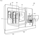
- FIG. 1 is a diagram showing the appearance of the machine tool 100.
- the term "machine tool” as used in the present specification is a concept that includes various types of devices that have the function of processing a workpiece.
- the machine tool 100 may be a horizontal machining center or a vertical machining center.
- the machine tool 100 may be a lathe, an additive processing machine, or another type of cutting machine or grinding machine.
- the machine tool 100 has a tool storage unit 40A and a machining body 40B.
- the tool storage unit 40A and the machining body 40B are partitioned by a cover.
- a magazine 150 and an ATC (Automatic Tool Changer) 160 are provided in the tool storage unit 40A.
- a spindle 170 is provided in the machining body 40B.
- a worker can load tools into the magazine 150 through a door D1.
- the machining body 40B processes a workpiece using at least one of various tools held in the magazine 150.
- the machine tool 100 drives the magazine 150 to move one tool (hereinafter also referred to as the "next tool") that corresponds to a machining process to a first tool exchange position.
- the machine tool 100 also drives the spindle 170 to move the tool mounted on the spindle 170 (hereinafter also referred to as the "used tool") to a second tool exchange position.
- the ATC 160 exchanges the next tool waiting at the first tool exchange position with the used tool waiting at the second tool exchange position.
- Tools are exchanged via a door D2 provided in the partition between the machining body 40B and the tool storage unit 40A.
- the door D2 is a sliding door, for example, and is opened and closed by a drive source such as a motor.
- the spindle 170 processes the workpiece using the next tool that was mounted.
- the machine tool 100 is also provided with an operation panel 500.
- the operation panel 500 includes a display 505 for displaying various types of information regarding machining, and operation keys 506 for receiving various types of operations performed on the machine tool 100.
- FIG. 2 is a diagram showing an example of the drive mechanism of the machine tool 100.
- the machine tool 100 includes a control unit 50, drive units 110, 120, and 130, the magazine 150, the ATC 160, and the spindle 170.
- the gravitational direction will also be referred to as the "X-axis direction” below.
- the direction orthogonal to the X-axis on the horizontal plane will also be referred to as the "Y-axis direction”.
- the direction orthogonal to both the X-axis direction and the Y-axis direction will also be referred to as the "Z-axis direction”.
- control unit 50 in the present specification means the device that controls the machine tool 100.
- the control unit 50 may have any device configuration.
- the control unit 50 may be constituted by a single control unit, or may be constituted by a plurality of control units.
- the control unit 50 is constituted by a CPU unit 200, a CNC unit 300, and an information processing device 400.
- the control unit 50 may include the above-described operation panel 500 (see FIG. 1 ).
- the CPU unit 200 and the CNC unit 300 communicate with each other via a bus B, for example.
- the CNC unit 300 and the information processing device 400 communicate with each other via a network NW, for example.
- the CPU unit 200 is a PLC (Programmable Logic Controller), for example.
- the CPU unit 200 controls the drive unit 110 in accordance with a PLC program designed in advance.
- This PLC program is written using a ladder program, for example.
- the drive unit 110 is a drive mechanism for driving the magazine 150 to rotate.
- the drive unit 110 may have any device configuration.
- the drive unit 110 may be constituted by a single drive unit, or may be constituted by a plurality of drive units. In the example shown in FIG. 2 , the drive unit 110 is constituted by a motor driver 111M and a motor 112M.
- the motor driver 111M drives the magazine 150 in accordance with control commands from the CPU unit 200.
- the magazine 150 is provided with the motor 112M.
- the motor 112M may be a servo motor, may be a stepping motor, or may be another type of motor.
- the motor driver 111M receives input of a target rotation speed from the CPU unit 200, and controls the motor 112M accordingly.
- the motor 112M drives the magazine 150 to rotate in accordance with an output current from the motor driver 111M, and drives a designated next tool T1 in the magazine 150 to a designated position.
- the CPU unit 200 controls the drive unit 120 in accordance with a PLC program designed in advance.
- the drive unit 120 is a drive mechanism for driving the ATC 160.
- the drive unit 120 may have any device configuration.
- the drive unit 120 may be constituted by a single drive unit, or may be constituted by a plurality of drive units. In the example shown in FIG. 2 , the drive unit 120 is constituted by an ATC driver 121A and motors 122A and 122B.
- the ATC driver 121A is a two-axis integrated driver, and controls the driving of the motors 122A and 122B connected to the ATC 160, for example.
- the ATC 160 includes a central shaft 165 and an arm 166.
- the arm 166 is a double arm that can hold two tools at the same time, for example.
- the arm 166 has a tool gripper 166A that extends from the central shaft 165 toward one side in the direction orthogonal to the axial direction of the central shaft 165 (e.g., toward one side in the X-axis direction), and a tool gripper 166B that extends from the central shaft 165 toward the opposite side.
- the motors 122A and 122B may be a servo motor, may be a stepping motor, or may be another type of motor.
- the ATC driver 121A receives input of a target rotation speed for the motor 122A and input of a target rotation speed for the motor 122B from the CPU unit 200, and controls the motors 122A and 122B accordingly.
- the motor 122A feeds the arm 166 of the ATC 160 in accordance with an output current from the ATC driver 121A, and drives the arm 166 to any position in the axial direction of the central shaft 165.
- the motor 122B drives the arm 166 of the ATC 160 to rotate in accordance with an output current from the ATC driver 121A, and drives the arm 166 to any rotation angle about the central shaft 165.
- the ATC 160 acquires the next tool T1 from the magazine 150 based on receiving a tool exchange command. Thereafter, the ATC 160 removes a used tool T2 from the spindle 170 and mounts the next tool T1 to the spindle 170. Thereafter, the ATC 160 stores the used tool T2, which was removed from the spindle 170, in the magazine 150.
- the CNC unit 300 Upon receiving a machining start command from the CPU unit 200, the CNC unit 300 starts the execution of a machining program designed in advance. This machining program is written using an NC (Numerical Control) program, for example.
- NC Numerical Control
- the CNC unit 300 drives the drive unit 130 in accordance with the machining program.
- the drive unit 130 is a drive mechanism for moving the spindle 170.
- the drive unit 130 may have any device configuration.
- the drive unit 130 may be constituted by a single drive unit, or may be constituted by a plurality of drive units.
- the drive unit 130 is constituted by motor drivers 131B, 131C, 131X, 131Y, and 131Z, and motors 132B, 132C, 132X, 132Y, and 132Z.
- the motor driver 131B successively receives input of target rotation speeds from the CNC unit 300, and controls the motor 132B accordingly.
- the motor 132B drives the spindle 170 to rotate around the Y-axis direction.
- the motor 132B may be an AC motor, may be a stepping motor, may be a servo motor, or may be another type of motor.
- the motor driver 131B calculates an actual rotation speed of the motor 132B based on a feedback signal from an encoder (not shown) for detecting the rotation angle of the motor 132B.
- the motor driver 131B increases the rotation speed of the motor 132B if the calculated actual rotation speed is smaller than the target rotation speed, and decreases the rotation speed of the motor 132B if the calculated actual rotation speed is larger than the target rotation speed. In this way, the motor driver 131B brings the rotation speed of the motor 132B closer to the target rotation speed while successively receiving feedback regarding the rotation speed of the motor 132B.
- the motor driver 131C successively receives input of target positions from the CNC unit 300, and controls motor 132C accordingly.
- the motor 132C drives the spindle 170 to rotate about the axial direction of the spindle 170.
- the motor 132C may be an AC motor, may be a stepping motor, may be a servo motor, or may be another type of motor.
- the control of the motor 132C by the motor driver 131C is performed by a method similar to the control performed by the motor driver 131B, and therefore a description thereof will not be repeated.
- the motor driver 131X successively receives input of target positions from the CNC unit 300, and controls the motor 132X accordingly.
- the motor 132X feeds the spindle 170, and moves the spindle 170 to any position in the X-axis direction.
- the motor 132X may be an AC motor, may be a stepping motor, may be a servo motor, or may be another type of motor.
- the control of the motor 132X by the motor driver 131X is performed by a method similar to the control performed by the motor driver 131B, and therefore a description thereof will not be repeated.
- the motor driver 131Y successively receives input of target positions from the CNC unit 300, and controls the motor 132Y accordingly.
- the motor 132Y feeds the spindle 170, and moves the spindle 170 to any position in the Y-axis direction.
- the motor 132Y may be an AC motor, may be a stepping motor, may be a servo motor, or may be another type of motor.
- the control of the motor 132Y by the motor driver 131Y is performed by a method similar to the control performed by the motor driver 131B, and therefore a description thereof will not be repeated.
- the motor driver 131Z successively receives input of target positions from the CNC unit 300, and controls the motor 132Z accordingly.
- the motor 132Z feeds the spindle 170, and moves the spindle 170 to any position in the Z-axis direction.
- the motor 132Z may be an AC motor, may be a stepping motor, may be a servo motor, or may be another type of motor.
- the control of the motor 132Z by the motor driver 131Z is performed by a method similar to the control performed by the motor driver 131B, and therefore a description thereof will not be repeated.
- the information processing device 400 is a computer.
- the information processing device 400 may be a desktop computer, may be a notebook computer, or may be tablet terminal.
- a camera 180 is connected to the information processing device 400.
- a predetermined image processing program is installed in the information processing device 400, and the information processing device 400 detects abnormal mounting of a tool based on an input image received from the camera 180. Details of the detection processing will be described later.
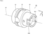
- FIG. 3 is a perspective view showing an HSK tooling 60.
- FIG. 4 is a side view of the HSK tooling 60 viewed from the X-axis direction shown in FIG. 3 .
- FIG. 5 is a cross-sectional view of the HSK tooling 60 viewed from the X-axis direction shown in FIG. 3 .
- the HSK tooling 60 is a type of tool standard specified by the ISO (International Organization for Standardization).
- the HSK tooling 60 functions as a connection interface between a tool and the machine tool 100.
- the HSK tooling 60 is constituted by a tool holder 62 (tool holding portion), a flange 63, and an HSK shank 64.
- the tool holder 62 is configured to be able to hold a tool.
- the tool holder 62 is connected to one end of the flange 63.
- the HSK shank 64 is connected to the other end of the flange 63.
- the HSK shank 64 has a hollow cylindrical portion.
- the inner surface and the outer surface of the cylindrical portion extend in the axial direction of a central axis AX.
- the axial direction of the central axis AX corresponds to the direction in which the tool is attached to and removed from the tool holder 62.
- the HSK shank 64 has a groove 65A (first groove) having a depth "DA" in the axial direction of the central axis AX, and a groove 65B (second groove) having a depth "DB" in the axial direction of the central axis AX.
- the direction that is parallel to the central axis AX and that is the direction in which the tool is attached to and removed from the HSK tooling 60 will also be referred to as the "Z-axis direction”.
- the direction that is orthogonal to the Z-axis direction and that is the direction from the groove 65A toward the groove 65B will also be referred to as the "X-axis direction”.
- the direction orthogonal to both the Z-axis direction and the X-axis direction will also be referred to as the "Y-axis direction”.
- the groove 65A has a recessed shape and is recessed in the Z-axis direction.
- the groove 65B has a recessed shape and is recessed in the Z-axis direction.
- the groove 65A and the groove 65B are provided at positions opposing each other across the central axis AX at the center.
- the depth “DA” of the groove 65A in the Z-axis direction is different from the depth "DB" of the groove 65B in the Z-axis direction.
- the depth "DA" of the groove 65A is shallower than the depth "DB" of the groove 65B.
- FIGS. 6 and 7 are diagrams schematically showing an aspect of mounting of the HSK tooling 60 to the tooling holding portion 70.
- the HSK tooling 60 functions as a connection interface between a tool T and the tooling holding portion 70.
- the "tooling holding portion 70" as used in the present specification means any unit capable of holding the HSK tooling 60.
- Examples of the tooling holding portion 70 include the above-described magazine 150 (see FIG. 1 ), the above-described ATC 160 (see FIG. 1 ), the above-described spindle 170 (see FIG. 1 ), and a tool rest (not shown).
- the tooling holding portion 70 has an insertion opening 75 for the HSK tooling 60.
- the insertion opening 75 is formed so as to match the shape of the HSK shank 64 described above.
- the HSK tooling 60 has the groove 65A that is recessed in the Z-axis direction.
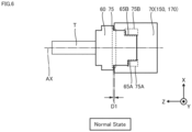
- the tooling holding portion 70 has an engaging portion 75A (first engaging portion) that engages with the groove 65A when the HSK shank 64 of the HSK tooling 60 is inserted into the insertion opening 75.
- the HSK tooling 60 has the groove 65B that is recessed in the Z-axis direction.
- the tooling holding portion 70 has an engaging portion 75B (second engaging portion) that engages with the groove 65B when the HSK shank 64 of the HSK tooling 60 is inserted into the insertion opening 75.
- the width of the engaging portion 75A in the central axis AX direction is equivalent to the depth "DA" (see FIG. 4 ) of the groove 65A in the central axis AX direction.
- the width of the engaging portion 75B in the axial direction of the central axis AX is equivalent to the depth "DB" (see FIG. 5 ) of the groove 65B in the axial direction of the central axis AX.
- the width of the engaging portion 75B in the central axis AX direction is longer than the width of the engaging portion 75A in the central axis AX direction.
- the two grooves 65A and 65B provided in the HSK tooling 60 are provided at positions opposing each other across the central axis AX at the center. Also, since the difference between the depth "DA" of the groove 65A and the depth "DB" of the groove 65B is very small, the HSK tooling 60 can possibly be mounted to the tooling holding portion 70 in a state inverted 180 degrees from the intended orientation.
- FIG. 6 shows a state in which the HSK tooling 60 is normally mounted to the tooling holding portion 70.
- the width of a gap between the HSK tooling 60 and the tooling holding portion 70 is "D1".
- FIG. 7 shows a state in which the HSK tooling 60 is abnormally mounted to the tooling holding portion 70.
- the width of the gap between the HSK tooling 60 and the tooling holding portion 70 is "D2".
- the width of the gap "D2" in the abnormally mounted state is longer than the width "D 1" of the gap in the normally mounted state.
- the machine tool 100 determines whether or not the HSK tooling 60 is normally mounted to the tooling holding portion 70 based on physical information indicating the state of the gap between the HSK tooling 60 and the tooling holding portion 70.
- physical information as used in the present specification is a concept that includes any indicator correlated with the width of the gap between the HSK tooling 60 and the tooling holding portion 70.
- the physical information includes image information showing the state of the gap between the HSK tooling 60 and the tooling holding portion 70.
- the physical information includes distance information indicating the width of the gap between the HSK tooling 60 and the tooling holding portion 70.
- the machine tool 100 executes predetermined warning processing. Accordingly, the worker can become aware that the HSK tooling 60 is abnormally mounted to the tooling holding portion 70.
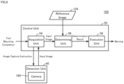
- FIG. 8 is a diagram showing an example of the functional configuration of the machine tool 100.
- the control unit 50 of the machine tool 100 includes an acquisition unit 54, a determining unit 56, and an execution unit 58 as functional components. These configurations will be described below in order.
- the functional components shown in FIG. 8 can be implemented in any unit constituting the control unit 50. In one example, some or all of the functional components shown in FIG. 8 are implemented in the above-described CPU unit 200 (see FIG. 2 ). In another example, some or all of the functional components shown in FIG. 8 are implemented in the above-described CNC unit 300 (see FIG. 2 ). In another example, some or all of the functional components shown in FIG. 8 are implemented in the above-described information processing device 400 (see FIG. 2 ). In another example, some or all of the functional components shown in FIG. 8 are implemented in the above-described operation panel 500 (see FIG. 1 ).
- FIG. 8 may be implemented in an external device such as a server, or may be implemented in dedicated hardware.
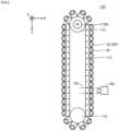
- FIG. 9 is a diagram showing the magazine 150 from the front.
- the acquisition unit 54 is implemented in the information processing device 400 (see FIG. 2 ).
- the acquisition unit 54 acquires physical information indicating the state of the gap between the HSK tooling 60 and the tooling holding portion 70 from a detection unit 45.
- the camera 180 is shown as an example of the detection unit 45.
- the acquisition unit 54 outputs an image capture instruction to the camera 180 at least at one timing while the HSK tooling 60 is mounted to the tooling holding portion 70. As a result, the acquisition unit 54 acquires, from the camera 180, a later-described input image 125 (see FIG. 10 ) showing the mounted portion between the HSK tooling 60 and the tooling holding portion 70, as the physical information.
- the camera 180 is provided to capture images of the magazine 150 in the tool storage unit 40A (see FIG. 1 ), for example.
- the magazine 150 includes a motor 112M, a driving sprocket 113, a driven sprocket 114, and an endless chain 115.
- the driving sprocket 113 is coupled to the output shaft of the above-described motor 112M (see FIG. 2 ).
- the driving sprocket 113 rotates while receiving motive power transmitted from the motor 112M.
- the endless chain 115 is wound around the driving sprocket 113 and the driven sprocket 114.
- motive power from the motor 112M is transmitted to the driven sprocket 114 via the endless chain 115.
- the driven sprocket 114 and the endless chain 115 rotate in conjunction with the driving sprocket 113.
- the endless chain 115 is provided with a plurality of pots 70P.
- the pots 70P are each an example of the above-described tooling holding portion 70 (see FIG. 6 ).
- One HSK tooling 60 can be mounted in each of the pots 70P.
- the machine tool 100 can drive a designated tool to any position by controlling the motor 112M.
- a worker can mount the HSK tooling 60 to the magazine 150. As a specific mounting procedure, the worker calls a pot 70P, and the machine tool 100 accordingly drives an empty pot 70P to a position in front of the above-described door D1. The worker then opens the door D1 and mounts the HSK tooling 60 to the empty pot 70P. The worker then closes the door D1.
- the acquisition unit 54 After the worker has mounted the HSK tooling 60 to the pot 70P, the acquisition unit 54 outputs an image capture instruction to the camera 180, and acquires a later-described input image 125 showing the mounted portion between the HSK tooling 60 and the pot 70P.
- the camera 180 is provided in the tool storage unit 40A (see FIG. 1 ) such that the gap between the HSK tooling 60 and the pot 70P is included in a field of view CR of the camera 180. Accordingly, the camera 180 acquires image information indicating the state of the gap between the HSK tooling 60 and the pot 70P.
- An image capture instruction is output to the camera 180 at any timing while the HSK tooling 60 is mounted to the tooling holding portion 70. Typically, an image capture instruction is output at the timing when the worker mounts the HSK tooling 60 to the pot 70P.
- the door D1 (see FIG. 1 ) of the machine tool 100 is provided with an open/closed sensor (not shown). After the HSK tooling 60 is mounted to a pot 70P, the worker closes the door D1. Accordingly, in the case where the output value of the open/closed sensor changes from a value indicating the open state of the door D1 to a value indicating the closed state of the door D1, the acquisition unit 54 outputs an image capture instruction to the camera 180.
- the machine tool 100 is provided with a tool mounting completion button (not shown). After the HSK tooling 60 is mounted to the pot 70P, the worker presses the mounting completion button. Therefore, based on the pressing of the mounting completion button, the acquisition unit 54 outputs an image capture instruction to the camera 180.
- the camera 180 does not necessarily need to be provided inside the tool storage unit 40A.
- the camera 180 may be provided inside the machining body 40B.
- the control unit 50 drives the above-described drive unit 130 to move the spindle 170, to which the HSK tooling 60 is mounted, to a position in front of the camera 180.
- the spindle 170 is an example of the above-described tooling holding portion 70 (see FIG. 6 ).
- the acquisition unit 54 then outputs an image capture instruction to the camera 180 and acquires an input image 125 showing the mounted portion between the HSK tooling 60 and the tooling holding portion 70.
- the camera 180 may be provided so as to capture images of a tool rest (not shown) in the machine tool 100.
- the tool rest is an example of the tooling holding portion 70 (see FIG. 6 ) described above.
- the tool rest has a turret.
- the turret is configured such that a plurality of HSK toolings 60 can be mounted thereto.
- the turret is configured to be able to rotate, and a HSK tooling 60 is rotated to a predetermined position when performing workpiece machining.
- the control unit 50 moves the HSK tooling 60 to a position in front of the camera 180.
- the acquisition unit 54 then outputs an image capture instruction to the camera 180 and acquires an input image 125 showing the mounted portion between the HSK tooling 60 and the tooling holding portion 70.
- the determining unit 56 is implemented in the information processing device 400 (see FIG. 2 ).
- FIG. 10 is a conceptual diagram schematically showing processing for detecting abnormal mounting of the HSK tooling 60.
- a reference image 124 and an input image 125 are shown in FIG. 10 .
- the determining unit 56 compares the input image 125 acquired by the acquisition unit 54 with the reference image 124, and determines whether or not the HSK tooling 60 is normally mounted to the tooling holding portion 70.
- the reference image 124 is an image of the HSK tooling 60 obtained in advance while the HSK tooling 60 is normally mounted to the tooling holding portion 70.
- the reference image 124 is stored in advance in a storage device of the machine tool 100, for example.
- the determining unit 56 generates a difference image 126 by subtracting the reference image 124 from the input image 125. The determining unit 56 then determines whether or not the HSK tooling 60 is normally mounted to the tooling holding portion 70 based on the difference image 126.
- the determining unit 56 assigns "0" (black) to pixels whose pixel value is less than or equal to a threshold value th in the difference image 126, and assigns "255" (white) to pixels whose pixel value is greater than the threshold value th in the difference image 126.
- the determining unit 56 thus generates a binarized image from the difference image 126.
- the determining unit 56 counts the number of pixels having a pixel value of "0”, and if the count value is greater than or equal to a predetermined value, it is determined that the HSK tooling 60 is normally mounted to the tooling holding portion 70. On the other hand, if the count value is less than the predetermined value, the determining unit 56 determines that the HSK tooling 60 is abnormally mounted to the tooling holding portion 70.
- the determining unit 56 does not necessarily need to use the reference image 124 when detecting abnormal mounting of the HSK tooling 60.
- Various image processing algorithms may be used for the detection processing.
- the determining unit 56 detects abnormal mounting of the HSK tooling 60 using a trained model.
- the trained model is generated in advance by learning processing performed using a training data set.
- the training data set includes a plurality of training images showing mounting states of the HSK tooling 60 and the tooling holding portion 70. Each training image is associated with a label indicating whether or not the HSK tooling 60 is normally mounted to the tooling holding portion 70.
- the internal parameters of the trained model have been optimized in advance through training processing performed using such a training data set.
- CNN convolutional neural network
- FCN full-layer convolutional neural network
- support vector machine a convolutional neural network
- the determining unit 56 Upon acquiring the input image 125 from the camera 180, the determining unit 56 inputs the input image 125 to the trained model. As a result, the trained model outputs a probability that the HSK tooling 60 is abnormally mounted. If the probability exceeds a predetermined value, the determining unit 56 determines that the HSK tooling 60 is abnormally mounted to the tooling holding portion 70.
- the execution unit 58 is implemented in the information processing device 400 described above or the operation panel 500 described above, for example.
- the execution unit 58 executes predetermined warning processing in the case where the determining unit 56 determines that the HSK tooling 60 is abnormally mounted to the tooling holding portion 70.
- the warning processing is processing for notifying the worker that the HSK tooling 60 is abnormally mounted to the tooling holding portion 70.
- the execution unit 58 displays a warning indicating abnormal mounting of the HSK tooling 60 on the display 505 of the operation panel 500.
- This warning includes a message prompting the worker to invert the HSK tooling 60 by 180 degrees and remount it to the tooling holding portion 70, for example. The worker can thus easily understand how to remount the HSK tooling 60 to the tooling holding portion 70.
- the warning may be displayed by another display unit.
- the mode in which the warning is output is not limited to display.
- the warning may be output as a sound such as a buzzer sound or speech.
- the warning may be sent to another device by an electronic message or the like.
- FIG. 11 is a diagram showing an example of the hardware configuration of the CPU unit 200.
- the CPU unit 200 includes a control circuit 201, a ROM (Read Only Memory) 202, a RAM (Random Access Memory) 203, a fieldbus controller 204, and an auxiliary storage device 220. These components are connected to an internal bus 209.
- the control circuit 201 is constituted by at least one integrated circuit, for example.
- An integrated circuit may be constituted by at least one CPU, at least one GPU (Graphics Processing Unit), at least one ASIC (Application Specific Integrated Circuit), at least one FPGA (Field Programmable Gate Array), or a combination thereof, for example.
- the control circuit 201 controls the operation of the CPU unit 200 by executing various programs, such as a control program 222. Upon receiving an execution command for the control program 222, the control circuit 201 reads the control program 222 from the auxiliary storage device 220 or the ROM 202 to the RAM 203.
- the RAM 203 functions as a working memory and temporarily stores various types of data necessary for executing the control program 222.
- the fieldbus controller 204 is a communication unit for realizing communication with various units connected to the fieldbus.
- Examples of communication standards that can be adopted for the field network include EtherCAT (registered trademark), EtherNet/IP (registered trademark), CC-Link (registered trademark), and CompoNet (registered trademark).
- Examples of units connected to the fieldbus include the motor driver 111M, the ATC driver 121A, and the CNC unit 300 that are described above.
- the auxiliary storage device 220 is a storage medium such as a hard disk or a flash memory, for example.
- the auxiliary storage device 220 stores the control program 222 and the like.
- the control program 222 is not limited to being stored in the auxiliary storage device 220, and can also be stored in a storage area (e.g., a cache memory) of the control circuit 201, the ROM 202, the RAM 203, an external device (e.g., a server), or the like.
- control program 222 may be provided as part of a program.
- various types of processing pertaining to the present embodiment are realized in cooperation with the program. Even if the program does not include such a portion of modules, the program does not depart from the spirit of the control program 222 pertaining to the present embodiment.
- some or all of the functions provided by the control program 222 may be realized by dedicated hardware.
- the CPU unit 200 may be configured in a mode such as a so-called cloud service in which at least one server executes a part of the processing of the control program 222.
- FIG. 12 is a diagram showing an example of the hardware configuration of the CNC unit 300.
- the CNC unit 300 includes a control circuit 301, a ROM 302, a RAM 303, a communication interface 304, a communication interface 305, a fieldbus controller 306, and an auxiliary storage device 320. These components are connected to an internal bus 309.
- the control circuit 301 is constituted by at least one integrated circuit, for example.
- An integrated circuit may be constituted by at least one CPU, at least one GPU, at least one ASIC, at least one FPGA, or a combination thereof, for example.
- the control circuit 301 controls the operation of the CNC unit 300 by executing various programs, such as a machining program 322.
- the machining program 322 is a program for realizing workpiece machining.
- the control circuit 301 Upon receiving an execution command for the machining program 322, the control circuit 301 reads the machining program 322 from the ROM 302 to the RAM 303.
- the RAM 303 functions as a working memory and temporarily stores various types of data necessary for executing the machining program 322.
- a LAN, a WLAN, Bluetooth (registered trademark), or the like is connected to the communication interface 304.
- the CNC unit 300 exchanges data with an external device via the communication interface 304.
- Examples of the external device include the above-described information processing device 400, the operation panel 500, and a server (not shown).
- the communication interface 305 is an interface for realizing communication with an external device.
- the CNC unit 300 exchanges data with an external device via the communication interface 305.
- the external device include various drive units for workpiece machining (e.g., the above-described motor drivers 131B, 131C, and 131X to 131Z).
- the fieldbus controller 306 is a communication unit for realizing communication with various units connected to a fieldbus. Examples of communication standards that can be adopted for the field network include EtherCAT, EtherNet/IP, CC-Link, and CompoNet. One example of a unit connected to the fieldbus is the CPU unit 200.
- the auxiliary storage device 320 is a storage medium such as a hard disk or a flash memory, for example.
- the auxiliary storage device 320 stores the machining program 322 and the like.
- the machining program 322 is not limited to being stored in the auxiliary storage device 320, and can also be stored in a storage area (e.g., a cache memory) of the control circuit 301, the ROM 302, the RAM 303, an external device (e.g., a server), or the like.
- FIG. 13 is a diagram showing an example of the hardware configuration of the information processing device 400.
- the information processing device 400 includes a control circuit 401, a ROM 402, a RAM 403, a communication interface 404, a camera interface 405, and an auxiliary storage device 420. These components are connected to an internal bus 409.
- the control circuit 401 is constituted by at least one integrated circuit, for example.
- An integrated circuit may be constituted by at least one CPU, at least one GPU, at least one ASIC, at least one FPGA, or a combination thereof, for example.
- the control circuit 401 controls the operation of the information processing device 400 by executing various programs, such as a control program 422 for detecting abnormal mounting of the HSK tooling 60. Upon receiving an execution command for any of various program, the control circuit 401 reads the program to be executed from the auxiliary storage device 420 or the ROM 402 to the RAM 403.
- the RAM 403 functions as a working memory and temporarily stores various types of data necessary for program execution.
- the communication interface 404 is an interface for realizing communication using a LAN, a WLAN, Bluetooth, or the like.
- the information processing device 400 exchanges data with an external device (e.g., the CNC unit 300 or a server) via the communication interface 404.
- the information processing device 400 may be configured to be able to download the control program 422 via the communication interface 404.
- the camera interface 405 is an interface for connecting to the camera 180 by wire or wirelessly.
- the camera 180 may be a CCD (Charge Coupled Device) camera, an infrared camera (thermography), or another type of camera.
- CCD Charge Coupled Device
- thermography infrared camera
- the auxiliary storage device 420 is a storage medium such as a hard disk or a flash memory, for example.
- the auxiliary storage device 420 stores the above-described reference image 124 and the control program 422, for example.
- the reference image 124 and the control program 422 are not limited to being stored in the auxiliary storage device 420, and can also be stored in a storage area (e.g., a cache memory) of the control circuit 401, the ROM 402, the RAM 403, an external device (e.g., a server), or the like.
- control program 422 may be provided as part of a program. In this case, processing pertaining to the present embodiment is realized in cooperation with the program. Even if the program does not include such a portion of modules, the program does not depart from the spirit of the machine tool 100 pertaining to the present embodiment. Also, some or all of the functions provided by the control program 422 pertaining to the present embodiment may be realized by dedicated hardware. Furthermore, processing pertaining to the present embodiment may be realized by cooperation between the machine tool 100 and a server. Furthermore, the information processing device 400 may be configured in a mode such as a so-called cloud service in which at least one server implements processing according to the present embodiment.
- FIG. 14 is a diagram showing an example of the hardware configuration of the operation panel 500.
- the operation panel 500 includes a control circuit 501, a ROM (Read Only Memory) 502, a RAM (Random Access Memory) 503, a communication interface 504, a display 505, operation keys 506, and an auxiliary storage device 520. These components are connected to an internal bus 509.
- the control circuit 501 is configured by at least one integrated circuit, for example.
- An integrated circuit may be comprised of at least one CPU, at least one GPU, at least one ASIC, at least one FPGA, or a combination thereof, for example.
- the control circuit 501 controls the operation of the operation panel 500 by executing various programs, such as a control program 522.
- the control program 522 defines commands for controlling the operation panel 500.
- the control circuit 501 Upon receiving an execution command for the control program 522, the control circuit 501 reads the control program 522 from the auxiliary storage device 520 or the ROM 502 to the RAM 503.
- the RAM 503 functions as a working memory and temporarily stores various types of data necessary for executing the control program 522.
- the communication interface 504 is a communication unit for realizing communication using a LAN (Local Area Network) cable, a WLAN, Bluetooth, or the like.
- the operation panel 500 realizes communication with an external device such as the above-described CNC unit 300 via the communication interface 504.
- the display 505 is a liquid crystal display, an organic EL display, or another display device, for example.
- the display 505 transmits an image signal for displaying an image to the display 505 in accordance with a command from the control circuit 501 or the like.
- the display 505 is constituted by a touch panel, for example, and receives various operations performed on the machine tool 100 through touch operations.
- the operation keys 506 are constituted by a plurality of hardware keys, and receive various user operations performed on the operation panel 500. Signals corresponding to pressed keys are output to control circuit 501.
- the auxiliary storage device 520 is a storage medium such as a hard disk or a flash memory, for example.
- the auxiliary storage device 520 stores the control program 522 and the like.
- the control program 522 is not limited to being stored in the auxiliary storage device 520, and can also be stored in a storage area (e.g., a cache memory) of the control circuit 501, the ROM 502, the RAM 503, an external device (e.g., a server), or the like.
- FIG. 15 is a flowchart showing part of the processing executed by the control unit 50 of the machine tool 100.
- the processing shown in FIG. 15 is realized by the control unit 50 executing a control program (e.g., the above-described control program 422 or the above-described control program 522). In other aspects, some or all of the processing may be executed by circuit elements or other hardware.
- a control program e.g., the above-described control program 422 or the above-described control program 522. In other aspects, some or all of the processing may be executed by circuit elements or other hardware.
- step S110 the control unit 50 determines whether or not an HSK tooling 60 has been mounted to the tooling holding portion 70.
- Various methods can be used to determine whether or not an HSK tooling 60 has been mounted to the tooling holding portion 70.
- the door D1 (see FIG. 1 ) of the machine tool 100 is provided with an open/closed sensor (not shown). Upon completing the mounting of the HSK tooling 60 to the tooling holding portion 70, the worker closes the door D1.
- the control unit 50 determines that an HSK tooling 60 has been mounted to the tooling holding portion 70.
- the machine tool 100 includes a mounting completion button (not shown). Upon completing the mounting of the HSK tooling 60 to the tooling holding portion 70, the worker presses the mounting completion button. Based on the fact that the mounting completion button was pressed, the control unit 50 determines that the HSK tooling 60 was mounted to the tooling holding portion 70.
- step S110 Upon determining that the HSK tooling 60 was mounted to the tooling holding portion 70 (YES in step S110), the control unit 50 switches the control to step S112. In the other case (NO in step S110), the control unit 50 executes the processing of step S110 again.
- step S112 the control unit 50 functions as the above-described acquisition unit 54 (see FIG. 8 ) and outputs an image capture instruction to the above-described camera 180. Thereby, the control unit 50 acquires the above-described input image 125 (see FIG. 10 ) show the mounting portion between the HSK tooling 60 and the tooling holding portion 70.
- step S114 the control unit 50 compares the input image 125 acquired in step S112 with the reference image 124.
- the reference image 124 and the input image 125 are compared by the method described above with reference to FIG. 10 and the like, and thus the description thereof will not be repeated.
- step S120 the control unit 50 functions as the above-described determining unit 56 (see FIG. 8 ), and determines whether or not the HSK tooling 60 is abnormally mounted to the tooling holding portion 70 based on the comparison result in step S114. Upon determining that the HSK tooling 60 is abnormally mounted to the tooling holding portion 70 (YES in step S120), the control unit 50 switches the control to step S122. In the other case (NO in step S120), the control unit 50 ends the processing shown in FIG. 15 .
- step S122 the control unit 50 functions as the above-described execution unit 58 (see FIG. 8 ) and executes predetermined warning processing.
- the control unit 50 displays a warning indicating abnormal mounting of the HSK tooling 60 on the display 505 of the operation panel 500.
- This warning includes a message prompting the worker to invert the HSK tooling 60 by 180 degrees and remount it to the tooling holding portion 70, for example.
- the machine tool 100 detects abnormal mounting of the HSK tooling 60 to the tooling holding portion 70 by using the camera 180 to capture an image of the state of the gap between the HSK tooling 60 and the tooling holding portion 70.
- the machine tool 100 detects abnormal mounting of the HSK tooling 60 to the tooling holding portion 70 with use of a position sensor for detecting physical information correlated with the width of the gap between the HSK tooling 60 and the tooling holding portion 70. Since aspects other than the point of using the position sensor are as described above, the description of aspects other than that will not be repeated below.
- FIGS. 16 and 17 are diagrams schematically showing aspects of mounting of the HSK tooling 60 to the tooling holding portion 70.
- the tooling holding portion 70 includes an interlocking member 90 that interlocks with the HSK shank 64 when the HSK shank 64 is inserted into the insertion opening 75.
- the interlocking member 90 is provided in the tooling holding portion 70 so as to be able to move in the axial direction relative to the central axis AX.
- the interlocking member 90 is a pin extending in the axial direction of the central axis AX.
- the tooling holding portion 70 includes a hole H.
- the hole H extends in the axial direction of the central axis AX.
- the interlocking member 90 is provided in the tooling holding portion 70 so as to pass through the hole H.
- FIG. 16 shows an aspect in which the HSK tooling 60 is normally mounted to the tooling holding portion 70.
- the groove 65A comes into contact with the interlocking member 90
- the groove 65B comes into contact with the engaging portion 75B.
- the interlocking member 90 is pushed in the insertion direction of the HSK tooling 60 (i.e., in the axial direction of the central axis AX) by the groove 65A.
- FIG. 17 shows an aspect in which the HSK tooling 60 is abnormally mounted to the tooling holding portion 70.
- the groove 65A comes into contact with the engaging portion 75B, and the groove 65B comes into contact with the interlocking member 90.
- the interlocking member 90 is pushed in the insertion direction of the HSK tooling 60 (i.e., in the axial direction of the central axis AX) by the groove 65B.
- the amount by which the interlocking member 90 moves when the HSK tooling 60 is inserted into the tooling holding portion 70 is correlated with the width of the gap between the HSK tooling 60 and the tooling holding portion 70. Therefore, the amount of movement can serve as an indicator for determining whether or not the HSK tooling 60 is normally mounted to the tooling holding portion 70.
- the machine tool 100 uses the position sensor 190 to detect the amount of movement of the interlocking member 90 when the HSK tooling 60 is mounted to the tooling holding portion 70.
- the position sensor 190 detects the position of the interlocking member 90 as physical information indicating the state of the gap between the HSK tooling 60 and the tooling holding portion 70.
- the position sensor 190 is a non-contact proximity sensor that can detect the presence or absence of an object within a detectable range.
- the position sensor 190 may be a contact-type switch capable of detecting contact with the interlocking member 90.
- the position sensor 190 may be a distance sensor capable of detecting the distance to the interlocking member 90.
- FIGS. 16 and 17 show a non-contact proximity sensor as an example of the position sensor 190.
- the position sensor 190 is provided in the tooling holding portion 70 such that when the HSK tooling 60 is mounted to the tooling holding portion 70, the interlocking member 90 moves into or out of the detectable range of the position sensor 190.
- the interlocking member 90 moves from outside the detectable range of the position sensor 190 to a position within the detectable range of the position sensor 190.
- the interlocking member 90 does not move to a position within the detectable range of the position sensor 190. Accordingly, the machine tool 10 can detect abnormal mounting of the HSK tooling 60 based on the output value of the position sensor 190.
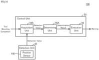
- FIG. 18 is a diagram showing an example of the functional configuration of the machine tool 100 according to a variation.
- the control unit 50 of the machine tool 100 includes an acquisition unit 54A, a determining unit 56A, and the execution unit 58 as functional components.
- the functional configuration shown in FIG. 18 is different from the functional configuration shown in FIG. 8 in that the acquisition unit 54A is provided in place of the acquisition unit 54, and the determining unit 56A is provided in place of the determining unit 56. Since the functions of the execution unit 58 are as described above, the description thereof will not be repeated below.
- the acquisition unit 54A is implemented in the information processing device 400 (see FIG. 2 ).
- the acquisition unit 54 acquires physical information indicating the state of the gap between the HSK tooling 60 and the tooling holding portion 70 from the detection unit 45.
- the above-described position sensor 190 is shown as an example of the detection unit 45.
- the position sensor 190 detects, as the physical information, a detection value indicating the state of the gap between the HSK tooling 60 and the tooling holding portion 70.
- the acquisition unit 54A may acquire the detection value of the position sensor 190 at any timing. Typically, the acquisition unit 54A acquires the detection value from the position sensor 190 when the worker has mounted the HSK tooling 60 to the tooling holding portion 70.
- the door D1 (see FIG. 1 ) of the machine tool 100 is provided with an open/closed sensor (not shown).
- the worker closes the door D1.
- the acquisition unit 54A acquires the detection value from the position sensor 190.
- the machine tool 100 includes a mounting completion button (not shown). Upon completing the mounting of the HSK tooling 60 to the tooling holding portion 70, the worker presses the mounting completion button. Therefore, based on the pressing of the mounting completion button, the acquisition unit 54A acquires the detection value from the position sensor 190.
- the determining unit 56A is implemented in the information processing device 400 (see FIG. 2 ).
- the determining unit 56A determines that the HSK tooling 60 is abnormally mounted to the tooling holding portion 70.
- the abnormal mounting determination algorithm used by the determining unit 56A is designed according to the type of the position sensor 190.
- the position sensor 190 is a proximity sensor that indicates the presence or absence of an object using binary values. In this case, if the output value of the position sensor 190 is "0", that indicates that the interlocking member 90 is not located at a position in front of the position sensor 190. On the other hand, if the output value of the position sensor 190 is "1", that indicates that the interlocking member 90 is located at a position in front of the position sensor 190.
- the determining unit 56A determines that the HSK tooling 60 is abnormally mounted to the tooling holding portion 70.
- the determining unit 56A determines that the HSK tooling 60 is normally mounted to the tooling holding portion 70.
- the position sensor 190 is a distance sensor that outputs the distance to an object. In this case, if the output value of the position sensor 190 is greater than or equal to the predetermined value, that indicates that the interlocking member 90 is not located at a position in front of the position sensor 190. On the other hand, if the output value of the position sensor 190 is less than the predetermined value, that indicates that the interlocking member 90 is located at a position in front of the position sensor 190.
- the determining unit 56A determines that the HSK tooling 60 is abnormally mounted to the tooling holding portion 70.
- the determining unit 56A determines that the HSK tooling 60 is normally mounted to the tooling holding portion 70.
- the machine tool 100 acquires physical information indicating the state of the gap between the HSK tooling 60 and the tooling holding portion 70 from the detection unit 45. Based on that physical information, the machine tool 100 determines whether or not the HSK tooling 60 is normally mounted to the tooling holding portion 70. If the HSK tooling 60 is not normally mounted to the tooling holding portion 70, the machine tool 100 executes predetermined warning processing. Accordingly, the worker can become aware that the HSK tooling 60 is abnormally mounted to the tooling holding portion 70.
Landscapes
- Engineering & Computer Science (AREA)
- Mechanical Engineering (AREA)
- Physics & Mathematics (AREA)
- Optics & Photonics (AREA)
- Automatic Tool Replacement In Machine Tools (AREA)
- Machine Tool Sensing Apparatuses (AREA)
- Gripping On Spindles (AREA)
- Numerical Control (AREA)
Abstract
Description
- The present disclosure relates to a machine tool, a control method, and a control program.
-
JP 2006-315158 - Patent Document 1:
JP 2006-315158A - A tool is mounted to the machine tool via a tooling. In other words, the tooling functions as a connection interface between the tool and the machine tool.
- The tooling is constituted by a tool holder, which is the tool holding portion, and a shank, which is the portion for connection to the machine tool. Examples of shank standards include a BT shank, a BBT shank, and an HSK shank. The machine tool disclosed in
Patent Document 1 detects a mounting abnormality with regard to the tool holder of a BT shank or a BBT shank. - An HSK shank is provided with two grooves that have with different depths. When an HSK shank is inserted into the tooling holding portion of a spindle or a magazine, the two grooves of the HSK shank engage with one or two engaging portions provided in the tooling holding portion. The tooling is fixed to the tooling holding portion in this way.
- The two grooves provided in the HSK shank are provided so as to oppose each other. Because the difference between the depths of the grooves is very small, the HSK shank can possibly be mounted to the tooling holding portion in a state inverted 180 degrees from the intended orientation. If machining is performed while the HSK shank is abnormally mounted to the tooling holding portion, the workpiece machining accuracy may decrease. There is also a possibility that the HSK shank may fall while performing workpiece machining. If the HSK shank falls, there is a risk of damage to the workpiece, the tool, or the body of the machine tool. Therefore, there is desire for a technology for detecting abnormal mounting of an HSK shank to a machine tool.
- In a first aspect of the present disclosure, a machine tool includes a tooling holding portion having an insertion opening for a tooling. The tooling includes a tool holding portion configured to hold a tool, and an HSK shank configured to be inserted into the insertion opening. The machine tool further includes: a detection unit configured to detect physical information indicating a state of a gap between the tooling and the tooling holding portion; and a control unit configured to control the machine tool. The control unit includes an acquisition unit configured to acquire the physical information from the detection unit while the tooling is mounted to the tooling holding portion, a determining unit configured to determine, based on the acquired physical information, whether or not the tooling is mounted to the tooling holding portion in an inverted state of being inverted around an insertion direction in which the tooling is inserted into the tooling holding portion, and an execution unit configured to execute predetermined processing in a case where the determining unit determined that the tooling is mounted to the tooling holding portion in the inverted state.
- In an aspect of the present disclosure, the detection unit includes a camera. The camera is configured to acquire, as the physical information, an image showing the gap.
- In an aspect of the present disclosure, the tooling holding portion includes an interlocking member configured to interlock with the HSK shank when the HSK shank is inserted into the insertion opening. The detection unit includes a position sensor configured to detect a position of the interlocking member as the physical information.
- In an aspect of the present disclosure, the HSK shank includes a cylindrical portion. The cylindrical portion includes a first groove having a first depth in a direction along a central axis of the cylindrical portion, and a second groove having a second depth in the direction along the central axis of the cylindrical portion. The second depth is different from the first depth. The tooling holding portion includes a first engaging portion configured to engage with the first groove when the HSK shank is inserted into the insertion opening, and a second engaging portion configured to engage with the second groove when the HSK shank is inserted into the insertion opening.
- In an aspect of the present disclosure, in a case where the physical information indicates that a width of the gap is greater than or equal to a predetermined value, the determining unit determines that the tooling is mounted to the tooling holding portion in the inverted state.
- In an aspect of the present disclosure, the tooling holding portion includes at least one of a magazine, a spindle, and a tool rest.
- In another aspect of the present disclosure, a control method for controlling a machine tool is provided. The machine tool includes a tooling holding portion having an insertion opening for a tooling. The tooling includes a tool holding portion configured to hold a tool, and an HSK shank configured to be inserted into the insertion opening. The machine tool further includes a detection unit configured to detect physical information indicating a state of a gap between the tooling and the tooling holding portion. The control method includes: a step of acquiring the physical information from the detection unit while the tooling is mounted to the tooling holding portion; a step of determining, based on the acquired physical information, whether or not the tooling is mounted to the tooling holding portion in an inverted state of being inverted around an insertion direction in which the tooling is inserted into the tooling holding portion; and a step of executing predetermined processing in a case where it was determined that the tooling is mounted to the tooling holding portion in the inverted state.
- In another aspect of the present disclosure, a control program for controlling a machine tool is provided. The machine tool includes a tooling holding portion having an insertion opening for a tooling. The tooling includes a tool holding portion configured to hold a tool, and an HSK shank configured to be inserted into the insertion opening. The machine tool further includes a detection unit configured to detect physical information indicating a state of a gap between the tooling and the tooling holding portion. The control program causes the machine tool to execute: a step of acquiring the physical information from the detection unit while the tooling is mounted to the tooling holding portion; a step of determining, based on the acquired physical information, whether or not the tooling is mounted to the tooling holding portion in an inverted state of being inverted around an insertion direction in which the tooling is inserted into the tooling holding portion; and a step of executing predetermined processing in a case where it was determined that the tooling is mounted to the tooling holding portion in the inverted state.
- These and other objects, features, aspects, and advantages of the present invention will become apparent from the following detailed description of the invention, taken in conjunction with the accompanying drawings.
-
-
FIG. 1 is a diagram showing the appearance of a machine tool. -
FIG. 2 is a diagram showing an example of a drive mechanism of the machine tool. -
FIG. 3 is a perspective view showing an HSK tooling. -
FIG. 4 is a side view of the HSK tooling viewed from an X-axis direction shown inFIG. 3 . -
FIG. 5 is a cross-sectional view of the HSK tooling viewed from the X-axis direction shown inFIG. 3 . -
FIG. 6 is a diagram schematically showing an aspect of mounting of the HSK tooling to a tooling holding portion. -
FIG. 7 is a diagram schematically showing an aspect of mounting of the HSK tooling to the tooling holding portion. -
FIG. 8 is a diagram showing an example of a functional configuration of the machine tool. -
FIG. 9 is a front view of a magazine. -
FIG. 10 is a conceptual diagram schematically showing processing for detecting abnormal mounting of the HSK tooling. -
FIG. 11 is a diagram showing an example of a hardware configuration of a CPU (Central Processing Unit) unit. -
FIG. 12 is a diagram showing an example of a hardware configuration of a CNC (Computer Numerical Control) unit. -
FIG. 13 is a diagram showing an example of a hardware configuration of an information processing device. -
FIG. 14 is a diagram showing an example of a hardware configuration of an operation panel. -
FIG. 15 is a flowchart showing part of processing executed by a control unit of the machine tool. -
FIG. 16 is a diagram schematically showing an aspect of mounting of the HSK tooling to the tooling holding portion. -
FIG. 17 is a diagram schematically showing an aspect of mounting of the HSK tooling to the tooling holding portion. -
FIG. 18 is a diagram showing an example of a functional configuration of a machine tool according to a variation. - Hereinafter, embodiments of the present invention will be described with reference to the drawings. In the following description, parts and constituent elements that are the same are denoted by the same reference numerals. They also have the same names and functions. Therefore, detailed description thereof will not be repeated. Note that the embodiments and the variations described below may be selectively combined as appropriate.
- First, a
machine tool 100 according to an embodiment will be described with reference toFIG. 1. FIG. 1 is a diagram showing the appearance of themachine tool 100. - The term "machine tool" as used in the present specification is a concept that includes various types of devices that have the function of processing a workpiece. The
machine tool 100 may be a horizontal machining center or a vertical machining center. Alternatively, themachine tool 100 may be a lathe, an additive processing machine, or another type of cutting machine or grinding machine. - The
machine tool 100 has atool storage unit 40A and amachining body 40B. Thetool storage unit 40A and themachining body 40B are partitioned by a cover. - A
magazine 150 and an ATC (Automatic Tool Changer) 160 are provided in thetool storage unit 40A. Aspindle 170 is provided in themachining body 40B. - A worker can load tools into the
magazine 150 through a door D1. Themachining body 40B processes a workpiece using at least one of various tools held in themagazine 150. - More specifically, the
machine tool 100 drives themagazine 150 to move one tool (hereinafter also referred to as the "next tool") that corresponds to a machining process to a first tool exchange position. Themachine tool 100 also drives thespindle 170 to move the tool mounted on the spindle 170 (hereinafter also referred to as the "used tool") to a second tool exchange position. Thereafter, theATC 160 exchanges the next tool waiting at the first tool exchange position with the used tool waiting at the second tool exchange position. Tools are exchanged via a door D2 provided in the partition between themachining body 40B and thetool storage unit 40A. The door D2 is a sliding door, for example, and is opened and closed by a drive source such as a motor. Thereafter, thespindle 170 processes the workpiece using the next tool that was mounted. - The
machine tool 100 is also provided with anoperation panel 500. Theoperation panel 500 includes adisplay 505 for displaying various types of information regarding machining, andoperation keys 506 for receiving various types of operations performed on themachine tool 100. - Next, various configurations of the
machine tool 100 will be described with reference toFIG. 2. FIG. 2 is a diagram showing an example of the drive mechanism of themachine tool 100. - As shown in
FIG. 2 , themachine tool 100 includes acontrol unit 50,drive units magazine 150, theATC 160, and thespindle 170. - For convenience in the description, the gravitational direction will also be referred to as the "X-axis direction" below. The direction orthogonal to the X-axis on the horizontal plane will also be referred to as the "Y-axis direction". The direction orthogonal to both the X-axis direction and the Y-axis direction will also be referred to as the "Z-axis direction".
- The "
control unit 50" in the present specification means the device that controls themachine tool 100. Thecontrol unit 50 may have any device configuration. Thecontrol unit 50 may be constituted by a single control unit, or may be constituted by a plurality of control units. In the example shown inFIG. 2 , thecontrol unit 50 is constituted by aCPU unit 200, aCNC unit 300, and aninformation processing device 400. Note that thecontrol unit 50 may include the above-described operation panel 500 (seeFIG. 1 ). - The
CPU unit 200 and theCNC unit 300 communicate with each other via a bus B, for example. TheCNC unit 300 and theinformation processing device 400 communicate with each other via a network NW, for example. - The
CPU unit 200 is a PLC (Programmable Logic Controller), for example. TheCPU unit 200 controls thedrive unit 110 in accordance with a PLC program designed in advance. This PLC program is written using a ladder program, for example. - The
drive unit 110 is a drive mechanism for driving themagazine 150 to rotate. Thedrive unit 110 may have any device configuration. Thedrive unit 110 may be constituted by a single drive unit, or may be constituted by a plurality of drive units. In the example shown inFIG. 2 , thedrive unit 110 is constituted by amotor driver 111M and amotor 112M. - The
motor driver 111M drives themagazine 150 in accordance with control commands from theCPU unit 200. Themagazine 150 is provided with themotor 112M. Themotor 112M may be a servo motor, may be a stepping motor, or may be another type of motor. - As more specific processing, the
motor driver 111M receives input of a target rotation speed from theCPU unit 200, and controls themotor 112M accordingly. Themotor 112M drives themagazine 150 to rotate in accordance with an output current from themotor driver 111M, and drives a designated next tool T1 in themagazine 150 to a designated position. - Also, the
CPU unit 200 controls thedrive unit 120 in accordance with a PLC program designed in advance. Thedrive unit 120 is a drive mechanism for driving theATC 160. Thedrive unit 120 may have any device configuration. Thedrive unit 120 may be constituted by a single drive unit, or may be constituted by a plurality of drive units. In the example shown inFIG. 2 , thedrive unit 120 is constituted by anATC driver 121A andmotors 122A and 122B. - The
ATC driver 121A is a two-axis integrated driver, and controls the driving of themotors 122A and 122B connected to theATC 160, for example. TheATC 160 includes acentral shaft 165 and anarm 166. Thearm 166 is a double arm that can hold two tools at the same time, for example. Specifically, thearm 166 has atool gripper 166A that extends from thecentral shaft 165 toward one side in the direction orthogonal to the axial direction of the central shaft 165 (e.g., toward one side in the X-axis direction), and atool gripper 166B that extends from thecentral shaft 165 toward the opposite side. - The
motors 122A and 122B may be a servo motor, may be a stepping motor, or may be another type of motor. For example, theATC driver 121A receives input of a target rotation speed for the motor 122A and input of a target rotation speed for themotor 122B from theCPU unit 200, and controls themotors 122A and 122B accordingly. The motor 122A feeds thearm 166 of theATC 160 in accordance with an output current from theATC driver 121A, and drives thearm 166 to any position in the axial direction of thecentral shaft 165. Themotor 122B drives thearm 166 of theATC 160 to rotate in accordance with an output current from theATC driver 121A, and drives thearm 166 to any rotation angle about thecentral shaft 165. - In one example, the
ATC 160 acquires the next tool T1 from themagazine 150 based on receiving a tool exchange command. Thereafter, theATC 160 removes a used tool T2 from thespindle 170 and mounts the next tool T1 to thespindle 170. Thereafter, theATC 160 stores the used tool T2, which was removed from thespindle 170, in themagazine 150. - Upon receiving a machining start command from the
CPU unit 200, theCNC unit 300 starts the execution of a machining program designed in advance. This machining program is written using an NC (Numerical Control) program, for example. TheCNC unit 300 drives thedrive unit 130 in accordance with the machining program. - The
drive unit 130 is a drive mechanism for moving thespindle 170. Thedrive unit 130 may have any device configuration. Thedrive unit 130 may be constituted by a single drive unit, or may be constituted by a plurality of drive units. In the example shown inFIG. 2 , thedrive unit 130 is constituted bymotor drivers motors - The
motor driver 131B successively receives input of target rotation speeds from theCNC unit 300, and controls themotor 132B accordingly. Themotor 132B drives thespindle 170 to rotate around the Y-axis direction. Themotor 132B may be an AC motor, may be a stepping motor, may be a servo motor, or may be another type of motor. - In the case where the
motor 132B is a servo motor, themotor driver 131B calculates an actual rotation speed of themotor 132B based on a feedback signal from an encoder (not shown) for detecting the rotation angle of themotor 132B. Themotor driver 131B increases the rotation speed of themotor 132B if the calculated actual rotation speed is smaller than the target rotation speed, and decreases the rotation speed of themotor 132B if the calculated actual rotation speed is larger than the target rotation speed. In this way, themotor driver 131B brings the rotation speed of themotor 132B closer to the target rotation speed while successively receiving feedback regarding the rotation speed of themotor 132B. - The
motor driver 131C successively receives input of target positions from theCNC unit 300, and controls motor 132C accordingly. Themotor 132C drives thespindle 170 to rotate about the axial direction of thespindle 170. Themotor 132C may be an AC motor, may be a stepping motor, may be a servo motor, or may be another type of motor. The control of themotor 132C by themotor driver 131C is performed by a method similar to the control performed by themotor driver 131B, and therefore a description thereof will not be repeated. - The
motor driver 131X successively receives input of target positions from theCNC unit 300, and controls themotor 132X accordingly. Themotor 132X feeds thespindle 170, and moves thespindle 170 to any position in the X-axis direction. Themotor 132X may be an AC motor, may be a stepping motor, may be a servo motor, or may be another type of motor. The control of themotor 132X by themotor driver 131X is performed by a method similar to the control performed by themotor driver 131B, and therefore a description thereof will not be repeated. - The
motor driver 131Y successively receives input of target positions from theCNC unit 300, and controls themotor 132Y accordingly. Themotor 132Y feeds thespindle 170, and moves thespindle 170 to any position in the Y-axis direction. Themotor 132Y may be an AC motor, may be a stepping motor, may be a servo motor, or may be another type of motor. The control of themotor 132Y by themotor driver 131Y is performed by a method similar to the control performed by themotor driver 131B, and therefore a description thereof will not be repeated. - The
motor driver 131Z successively receives input of target positions from theCNC unit 300, and controls themotor 132Z accordingly. Themotor 132Z feeds thespindle 170, and moves thespindle 170 to any position in the Z-axis direction. Themotor 132Z may be an AC motor, may be a stepping motor, may be a servo motor, or may be another type of motor. The control of themotor 132Z by themotor driver 131Z is performed by a method similar to the control performed by themotor driver 131B, and therefore a description thereof will not be repeated. - The
information processing device 400 is a computer. For example, theinformation processing device 400 may be a desktop computer, may be a notebook computer, or may be tablet terminal. - A
camera 180 is connected to theinformation processing device 400. A predetermined image processing program is installed in theinformation processing device 400, and theinformation processing device 400 detects abnormal mounting of a tool based on an input image received from thecamera 180. Details of the detection processing will be described later. - Next, the structure of an HSK tooling will be described with reference to
FIGS. 3 to 5 .FIG. 3 is a perspective view showing anHSK tooling 60.FIG. 4 is a side view of theHSK tooling 60 viewed from the X-axis direction shown inFIG. 3 .FIG. 5 is a cross-sectional view of theHSK tooling 60 viewed from the X-axis direction shown inFIG. 3 . - The
HSK tooling 60 is a type of tool standard specified by the ISO (International Organization for Standardization). TheHSK tooling 60 functions as a connection interface between a tool and themachine tool 100. - The
HSK tooling 60 is constituted by a tool holder 62 (tool holding portion), aflange 63, and anHSK shank 64. - The
tool holder 62 is configured to be able to hold a tool. Thetool holder 62 is connected to one end of theflange 63. - The
HSK shank 64 is connected to the other end of theflange 63. TheHSK shank 64 has a hollow cylindrical portion. The inner surface and the outer surface of the cylindrical portion extend in the axial direction of a central axis AX. The axial direction of the central axis AX corresponds to the direction in which the tool is attached to and removed from thetool holder 62. Also, theHSK shank 64 has agroove 65A (first groove) having a depth "DA" in the axial direction of the central axis AX, and agroove 65B (second groove) having a depth "DB" in the axial direction of the central axis AX. - For convenience in the description, hereinafter, the direction that is parallel to the central axis AX and that is the direction in which the tool is attached to and removed from the
HSK tooling 60 will also be referred to as the "Z-axis direction". Also, the direction that is orthogonal to the Z-axis direction and that is the direction from thegroove 65A toward thegroove 65B will also be referred to as the "X-axis direction". Moreover, the direction orthogonal to both the Z-axis direction and the X-axis direction will also be referred to as the "Y-axis direction". - The
groove 65A has a recessed shape and is recessed in the Z-axis direction. Similarly, thegroove 65B has a recessed shape and is recessed in the Z-axis direction. Thegroove 65A and thegroove 65B are provided at positions opposing each other across the central axis AX at the center. - The depth "DA" of the
groove 65A in the Z-axis direction is different from the depth "DB" of thegroove 65B in the Z-axis direction. In the example shown inFIGS. 4 and5 , the depth "DA" of thegroove 65A is shallower than the depth "DB" of thegroove 65B. - Next, an aspect of mounting of the
HSK tooling 60 to thetooling holding portion 70 will be described with reference toFIGS. 6 and7 .FIGS. 6 and7 are diagrams schematically showing an aspect of mounting of theHSK tooling 60 to thetooling holding portion 70. - As shown in
FIGS. 6 and7 , theHSK tooling 60 functions as a connection interface between a tool T and thetooling holding portion 70. The "tooling holding portion 70" as used in the present specification means any unit capable of holding theHSK tooling 60. Examples of thetooling holding portion 70 include the above-described magazine 150 (seeFIG. 1 ), the above-described ATC 160 (seeFIG. 1 ), the above-described spindle 170 (seeFIG. 1 ), and a tool rest (not shown). - The
tooling holding portion 70 has aninsertion opening 75 for theHSK tooling 60. Theinsertion opening 75 is formed so as to match the shape of theHSK shank 64 described above. - As described above, the
HSK tooling 60 has thegroove 65A that is recessed in the Z-axis direction. Correspondingly, thetooling holding portion 70 has an engagingportion 75A (first engaging portion) that engages with thegroove 65A when theHSK shank 64 of theHSK tooling 60 is inserted into theinsertion opening 75. - Furthermore, the
HSK tooling 60 has thegroove 65B that is recessed in the Z-axis direction. Correspondingly, thetooling holding portion 70 has an engagingportion 75B (second engaging portion) that engages with thegroove 65B when theHSK shank 64 of theHSK tooling 60 is inserted into theinsertion opening 75. - The width of the engaging
portion 75A in the central axis AX direction is equivalent to the depth "DA" (seeFIG. 4 ) of thegroove 65A in the central axis AX direction. The width of the engagingportion 75B in the axial direction of the central axis AX is equivalent to the depth "DB" (seeFIG. 5 ) of thegroove 65B in the axial direction of the central axis AX. Also, the width of the engagingportion 75B in the central axis AX direction is longer than the width of the engagingportion 75A in the central axis AX direction. - As described above, the two
grooves HSK tooling 60 are provided at positions opposing each other across the central axis AX at the center. Also, since the difference between the depth "DA" of thegroove 65A and the depth "DB" of thegroove 65B is very small, theHSK tooling 60 can possibly be mounted to thetooling holding portion 70 in a state inverted 180 degrees from the intended orientation. -
FIG. 6 shows a state in which theHSK tooling 60 is normally mounted to thetooling holding portion 70. As shown inFIG. 6 , when theHSK tooling 60 is normally mounted to thetooling holding portion 70, the width of a gap between theHSK tooling 60 and thetooling holding portion 70 is "D1". -
FIG. 7 shows a state in which theHSK tooling 60 is abnormally mounted to thetooling holding portion 70. As shown inFIG. 7 , in the case where theHSK tooling 60 is mounted to thetooling holding portion 70 in an inverted state, the width of the gap between theHSK tooling 60 and thetooling holding portion 70 is "D2". The width of the gap "D2" in the abnormally mounted state is longer than the width "D 1" of the gap in the normally mounted state. - In view of this, the
machine tool 100 determines whether or not theHSK tooling 60 is normally mounted to thetooling holding portion 70 based on physical information indicating the state of the gap between theHSK tooling 60 and thetooling holding portion 70. The term "physical information" as used in the present specification is a concept that includes any indicator correlated with the width of the gap between theHSK tooling 60 and thetooling holding portion 70. As one example, the physical information includes image information showing the state of the gap between theHSK tooling 60 and thetooling holding portion 70. As another example, the physical information includes distance information indicating the width of the gap between theHSK tooling 60 and thetooling holding portion 70. - In the case of determining that the
HSK tooling 60 is not normally mounted to thetooling holding portion 70, themachine tool 100 executes predetermined warning processing. Accordingly, the worker can become aware that theHSK tooling 60 is abnormally mounted to thetooling holding portion 70. - A functional configuration for detecting abnormal mounting of the
HSK tooling 60 will be described below with reference toFIGS. 8 to 10 .FIG. 8 is a diagram showing an example of the functional configuration of themachine tool 100. - The
control unit 50 of themachine tool 100 includes anacquisition unit 54, a determiningunit 56, and anexecution unit 58 as functional components. These configurations will be described below in order. - Note that the functional components shown in
FIG. 8 can be implemented in any unit constituting thecontrol unit 50. In one example, some or all of the functional components shown inFIG. 8 are implemented in the above-described CPU unit 200 (seeFIG. 2 ). In another example, some or all of the functional components shown inFIG. 8 are implemented in the above-described CNC unit 300 (seeFIG. 2 ). In another example, some or all of the functional components shown inFIG. 8 are implemented in the above-described information processing device 400 (seeFIG. 2 ). In another example, some or all of the functional components shown inFIG. 8 are implemented in the above-described operation panel 500 (seeFIG. 1 ). - Note that some of the functional components shown in
FIG. 8 may be implemented in an external device such as a server, or may be implemented in dedicated hardware. - First, functions of the
acquisition unit 54 shown inFIG. 8 will be described with reference toFIG. 9. FIG. 9 is a diagram showing themagazine 150 from the front. In one example, theacquisition unit 54 is implemented in the information processing device 400 (seeFIG. 2 ). - While the
HSK tooling 60 is mounted to thetooling holding portion 70, theacquisition unit 54 acquires physical information indicating the state of the gap between theHSK tooling 60 and thetooling holding portion 70 from adetection unit 45. InFIG. 8 , thecamera 180 is shown as an example of thedetection unit 45. - The
acquisition unit 54 outputs an image capture instruction to thecamera 180 at least at one timing while theHSK tooling 60 is mounted to thetooling holding portion 70. As a result, theacquisition unit 54 acquires, from thecamera 180, a later-described input image 125 (seeFIG. 10 ) showing the mounted portion between theHSK tooling 60 and thetooling holding portion 70, as the physical information. - The
camera 180 is provided to capture images of themagazine 150 in thetool storage unit 40A (seeFIG. 1 ), for example. Themagazine 150 includes amotor 112M, a drivingsprocket 113, a drivensprocket 114, and anendless chain 115. - The driving
sprocket 113 is coupled to the output shaft of the above-describedmotor 112M (seeFIG. 2 ). The drivingsprocket 113 rotates while receiving motive power transmitted from themotor 112M. - The
endless chain 115 is wound around the drivingsprocket 113 and the drivensprocket 114. As themotor 112M drives the drivingsprocket 113 to rotate, motive power from themotor 112M is transmitted to the drivensprocket 114 via theendless chain 115. As a result, the drivensprocket 114 and theendless chain 115 rotate in conjunction with the drivingsprocket 113. - Also, the
endless chain 115 is provided with a plurality ofpots 70P. Thepots 70P are each an example of the above-described tooling holding portion 70 (seeFIG. 6 ). OneHSK tooling 60 can be mounted in each of thepots 70P. Themachine tool 100 can drive a designated tool to any position by controlling themotor 112M. - A worker can mount the
HSK tooling 60 to themagazine 150. As a specific mounting procedure, the worker calls apot 70P, and themachine tool 100 accordingly drives anempty pot 70P to a position in front of the above-described door D1. The worker then opens the door D1 and mounts theHSK tooling 60 to theempty pot 70P. The worker then closes the door D1. - After the worker has mounted the
HSK tooling 60 to thepot 70P, theacquisition unit 54 outputs an image capture instruction to thecamera 180, and acquires a later-describedinput image 125 showing the mounted portion between theHSK tooling 60 and thepot 70P. - The
camera 180 is provided in thetool storage unit 40A (seeFIG. 1 ) such that the gap between theHSK tooling 60 and thepot 70P is included in a field of view CR of thecamera 180. Accordingly, thecamera 180 acquires image information indicating the state of the gap between theHSK tooling 60 and thepot 70P. - An image capture instruction is output to the
camera 180 at any timing while theHSK tooling 60 is mounted to thetooling holding portion 70. Typically, an image capture instruction is output at the timing when the worker mounts theHSK tooling 60 to thepot 70P. - More specifically, the door D1 (see
FIG. 1 ) of themachine tool 100 is provided with an open/closed sensor (not shown). After theHSK tooling 60 is mounted to apot 70P, the worker closes the door D1. Accordingly, in the case where the output value of the open/closed sensor changes from a value indicating the open state of the door D1 to a value indicating the closed state of the door D1, theacquisition unit 54 outputs an image capture instruction to thecamera 180. - In another example, the
machine tool 100 is provided with a tool mounting completion button (not shown). After theHSK tooling 60 is mounted to thepot 70P, the worker presses the mounting completion button. Therefore, based on the pressing of the mounting completion button, theacquisition unit 54 outputs an image capture instruction to thecamera 180. - Note that although the above example has been described on the assumption that the
camera 180 is provided inside thetool storage unit 40A, thecamera 180 does not necessarily need to be provided inside thetool storage unit 40A. For example, thecamera 180 may be provided inside themachining body 40B. In this case, thecontrol unit 50 drives the above-describeddrive unit 130 to move thespindle 170, to which theHSK tooling 60 is mounted, to a position in front of thecamera 180. Thespindle 170 is an example of the above-described tooling holding portion 70 (seeFIG. 6 ). Theacquisition unit 54 then outputs an image capture instruction to thecamera 180 and acquires aninput image 125 showing the mounted portion between theHSK tooling 60 and thetooling holding portion 70. - As another example, the
camera 180 may be provided so as to capture images of a tool rest (not shown) in themachine tool 100. The tool rest is an example of the tooling holding portion 70 (seeFIG. 6 ) described above. The tool rest has a turret. The turret is configured such that a plurality of HSK toolings 60 can be mounted thereto. The turret is configured to be able to rotate, and aHSK tooling 60 is rotated to a predetermined position when performing workpiece machining. When aHSK tooling 60 is mounted to the tool rest, thecontrol unit 50 moves theHSK tooling 60 to a position in front of thecamera 180. Theacquisition unit 54 then outputs an image capture instruction to thecamera 180 and acquires aninput image 125 showing the mounted portion between theHSK tooling 60 and thetooling holding portion 70. - Next, functions of the determining
unit 56 shown inFIG. 8 will be described with reference toFIG. 10 . In one example, the determiningunit 56 is implemented in the information processing device 400 (seeFIG. 2 ). -
FIG. 10 is a conceptual diagram schematically showing processing for detecting abnormal mounting of theHSK tooling 60. Areference image 124 and aninput image 125 are shown inFIG. 10 . The determiningunit 56 compares theinput image 125 acquired by theacquisition unit 54 with thereference image 124, and determines whether or not theHSK tooling 60 is normally mounted to thetooling holding portion 70. - The
reference image 124 is an image of theHSK tooling 60 obtained in advance while theHSK tooling 60 is normally mounted to thetooling holding portion 70. Thereference image 124 is stored in advance in a storage device of themachine tool 100, for example. - In one example, the determining
unit 56 generates adifference image 126 by subtracting thereference image 124 from theinput image 125. The determiningunit 56 then determines whether or not theHSK tooling 60 is normally mounted to thetooling holding portion 70 based on thedifference image 126. - More specifically, first, the determining
unit 56 assigns "0" (black) to pixels whose pixel value is less than or equal to a threshold value th in thedifference image 126, and assigns "255" (white) to pixels whose pixel value is greater than the threshold value th in thedifference image 126. The determiningunit 56 thus generates a binarized image from thedifference image 126. Thereafter, the determiningunit 56 counts the number of pixels having a pixel value of "0", and if the count value is greater than or equal to a predetermined value, it is determined that theHSK tooling 60 is normally mounted to thetooling holding portion 70. On the other hand, if the count value is less than the predetermined value, the determiningunit 56 determines that theHSK tooling 60 is abnormally mounted to thetooling holding portion 70. - Note that the determining
unit 56 does not necessarily need to use thereference image 124 when detecting abnormal mounting of theHSK tooling 60. Various image processing algorithms may be used for the detection processing. In one example, the determiningunit 56 detects abnormal mounting of theHSK tooling 60 using a trained model. - The trained model is generated in advance by learning processing performed using a training data set. The training data set includes a plurality of training images showing mounting states of the
HSK tooling 60 and thetooling holding portion 70. Each training image is associated with a label indicating whether or not theHSK tooling 60 is normally mounted to thetooling holding portion 70. The internal parameters of the trained model have been optimized in advance through training processing performed using such a training data set. - Various machine learning algorithms can be adopted as the training method for generating the trained model. For example, deep learning, a convolutional neural network (CNN), a full-layer convolutional neural network (FCN), a support vector machine, or the like is adopted as the machine learning algorithm.
- Upon acquiring the
input image 125 from thecamera 180, the determiningunit 56 inputs theinput image 125 to the trained model. As a result, the trained model outputs a probability that theHSK tooling 60 is abnormally mounted. If the probability exceeds a predetermined value, the determiningunit 56 determines that theHSK tooling 60 is abnormally mounted to thetooling holding portion 70. - Next, functions of the
execution unit 58 shown inFIG. 8 will be described. Theexecution unit 58 is implemented in theinformation processing device 400 described above or theoperation panel 500 described above, for example. - The
execution unit 58 executes predetermined warning processing in the case where the determiningunit 56 determines that theHSK tooling 60 is abnormally mounted to thetooling holding portion 70. The warning processing is processing for notifying the worker that theHSK tooling 60 is abnormally mounted to thetooling holding portion 70. - In one example, the
execution unit 58 displays a warning indicating abnormal mounting of theHSK tooling 60 on thedisplay 505 of theoperation panel 500. This warning includes a message prompting the worker to invert theHSK tooling 60 by 180 degrees and remount it to thetooling holding portion 70, for example. The worker can thus easily understand how to remount theHSK tooling 60 to thetooling holding portion 70. - Note that, in the above description, an example has been described in which a warning indicating abnormal mounting is displayed on the
display 505 of theoperation panel 500, but the warning may be displayed by another display unit. Also, the mode in which the warning is output is not limited to display. In one example, the warning may be output as a sound such as a buzzer sound or speech. Alternatively, the warning may be sent to another device by an electronic message or the like. - The hardware configuration of the above-described
CPU unit 200 shown inFIG. 2 will be described below with reference toFIG. 11. FIG. 11 is a diagram showing an example of the hardware configuration of theCPU unit 200. - The
CPU unit 200 includes acontrol circuit 201, a ROM (Read Only Memory) 202, a RAM (Random Access Memory) 203, afieldbus controller 204, and anauxiliary storage device 220. These components are connected to aninternal bus 209. - The
control circuit 201 is constituted by at least one integrated circuit, for example. An integrated circuit may be constituted by at least one CPU, at least one GPU (Graphics Processing Unit), at least one ASIC (Application Specific Integrated Circuit), at least one FPGA (Field Programmable Gate Array), or a combination thereof, for example. - The
control circuit 201 controls the operation of theCPU unit 200 by executing various programs, such as acontrol program 222. Upon receiving an execution command for thecontrol program 222, thecontrol circuit 201 reads thecontrol program 222 from theauxiliary storage device 220 or theROM 202 to theRAM 203. TheRAM 203 functions as a working memory and temporarily stores various types of data necessary for executing thecontrol program 222. - The
fieldbus controller 204 is a communication unit for realizing communication with various units connected to the fieldbus. Examples of communication standards that can be adopted for the field network include EtherCAT (registered trademark), EtherNet/IP (registered trademark), CC-Link (registered trademark), and CompoNet (registered trademark). Examples of units connected to the fieldbus include themotor driver 111M, theATC driver 121A, and theCNC unit 300 that are described above. - The
auxiliary storage device 220 is a storage medium such as a hard disk or a flash memory, for example. Theauxiliary storage device 220 stores thecontrol program 222 and the like. Note that thecontrol program 222 is not limited to being stored in theauxiliary storage device 220, and can also be stored in a storage area (e.g., a cache memory) of thecontrol circuit 201, theROM 202, theRAM 203, an external device (e.g., a server), or the like. - Furthermore, rather than being a standalone program, the
control program 222 may be provided as part of a program. In this case, various types of processing pertaining to the present embodiment are realized in cooperation with the program. Even if the program does not include such a portion of modules, the program does not depart from the spirit of thecontrol program 222 pertaining to the present embodiment. Also, some or all of the functions provided by thecontrol program 222 may be realized by dedicated hardware. Furthermore, theCPU unit 200 may be configured in a mode such as a so-called cloud service in which at least one server executes a part of the processing of thecontrol program 222. - Next, the hardware configuration of the above-described
CNC unit 300 shown inFIG. 2 will be described with reference toFIG. 12. FIG. 12 is a diagram showing an example of the hardware configuration of theCNC unit 300. - The
CNC unit 300 includes acontrol circuit 301, aROM 302, aRAM 303, acommunication interface 304, acommunication interface 305, afieldbus controller 306, and anauxiliary storage device 320. These components are connected to aninternal bus 309. - The
control circuit 301 is constituted by at least one integrated circuit, for example. An integrated circuit may be constituted by at least one CPU, at least one GPU, at least one ASIC, at least one FPGA, or a combination thereof, for example. - The
control circuit 301 controls the operation of theCNC unit 300 by executing various programs, such as amachining program 322. Themachining program 322 is a program for realizing workpiece machining. Upon receiving an execution command for themachining program 322, thecontrol circuit 301 reads themachining program 322 from theROM 302 to theRAM 303. TheRAM 303 functions as a working memory and temporarily stores various types of data necessary for executing themachining program 322. - A LAN, a WLAN, Bluetooth (registered trademark), or the like is connected to the
communication interface 304. TheCNC unit 300 exchanges data with an external device via thecommunication interface 304. Examples of the external device include the above-describedinformation processing device 400, theoperation panel 500, and a server (not shown). - The
communication interface 305 is an interface for realizing communication with an external device. In one example, theCNC unit 300 exchanges data with an external device via thecommunication interface 305. Examples of the external device include various drive units for workpiece machining (e.g., the above-describedmotor drivers - The
fieldbus controller 306 is a communication unit for realizing communication with various units connected to a fieldbus. Examples of communication standards that can be adopted for the field network include EtherCAT, EtherNet/IP, CC-Link, and CompoNet. One example of a unit connected to the fieldbus is theCPU unit 200. - The
auxiliary storage device 320 is a storage medium such as a hard disk or a flash memory, for example. Theauxiliary storage device 320 stores themachining program 322 and the like. Note that themachining program 322 is not limited to being stored in theauxiliary storage device 320, and can also be stored in a storage area (e.g., a cache memory) of thecontrol circuit 301, theROM 302, theRAM 303, an external device (e.g., a server), or the like. - Next, the hardware configuration of the
information processing device 400 shown inFIG. 2 will be described with reference toFIG. 13. FIG. 13 is a diagram showing an example of the hardware configuration of theinformation processing device 400. - The
information processing device 400 includes acontrol circuit 401, aROM 402, aRAM 403, acommunication interface 404, acamera interface 405, and anauxiliary storage device 420. These components are connected to aninternal bus 409. - The
control circuit 401 is constituted by at least one integrated circuit, for example. An integrated circuit may be constituted by at least one CPU, at least one GPU, at least one ASIC, at least one FPGA, or a combination thereof, for example. - The
control circuit 401 controls the operation of theinformation processing device 400 by executing various programs, such as acontrol program 422 for detecting abnormal mounting of theHSK tooling 60. Upon receiving an execution command for any of various program, thecontrol circuit 401 reads the program to be executed from theauxiliary storage device 420 or theROM 402 to theRAM 403. TheRAM 403 functions as a working memory and temporarily stores various types of data necessary for program execution. - The
communication interface 404 is an interface for realizing communication using a LAN, a WLAN, Bluetooth, or the like. Theinformation processing device 400 exchanges data with an external device (e.g., theCNC unit 300 or a server) via thecommunication interface 404. Theinformation processing device 400 may be configured to be able to download thecontrol program 422 via thecommunication interface 404. - The
camera interface 405 is an interface for connecting to thecamera 180 by wire or wirelessly. Thecamera 180 may be a CCD (Charge Coupled Device) camera, an infrared camera (thermography), or another type of camera. - The
auxiliary storage device 420 is a storage medium such as a hard disk or a flash memory, for example. Theauxiliary storage device 420 stores the above-describedreference image 124 and thecontrol program 422, for example. Note that thereference image 124 and thecontrol program 422 are not limited to being stored in theauxiliary storage device 420, and can also be stored in a storage area (e.g., a cache memory) of thecontrol circuit 401, theROM 402, theRAM 403, an external device (e.g., a server), or the like. - Note that rather than being a standalone program, the
control program 422 may be provided as part of a program. In this case, processing pertaining to the present embodiment is realized in cooperation with the program. Even if the program does not include such a portion of modules, the program does not depart from the spirit of themachine tool 100 pertaining to the present embodiment. Also, some or all of the functions provided by thecontrol program 422 pertaining to the present embodiment may be realized by dedicated hardware. Furthermore, processing pertaining to the present embodiment may be realized by cooperation between themachine tool 100 and a server. Furthermore, theinformation processing device 400 may be configured in a mode such as a so-called cloud service in which at least one server implements processing according to the present embodiment. - Next, the hardware configuration of the
operation panel 500 shown inFIG. 2 will be described with reference toFIG. 14. FIG. 14 is a diagram showing an example of the hardware configuration of theoperation panel 500. - The
operation panel 500 includes acontrol circuit 501, a ROM (Read Only Memory) 502, a RAM (Random Access Memory) 503, acommunication interface 504, adisplay 505,operation keys 506, and anauxiliary storage device 520. These components are connected to aninternal bus 509. - The
control circuit 501 is configured by at least one integrated circuit, for example. An integrated circuit may be comprised of at least one CPU, at least one GPU, at least one ASIC, at least one FPGA, or a combination thereof, for example. - The
control circuit 501 controls the operation of theoperation panel 500 by executing various programs, such as acontrol program 522. Thecontrol program 522 defines commands for controlling theoperation panel 500. Upon receiving an execution command for thecontrol program 522, thecontrol circuit 501 reads thecontrol program 522 from theauxiliary storage device 520 or theROM 502 to theRAM 503. TheRAM 503 functions as a working memory and temporarily stores various types of data necessary for executing thecontrol program 522. - The
communication interface 504 is a communication unit for realizing communication using a LAN (Local Area Network) cable, a WLAN, Bluetooth, or the like. In one example, theoperation panel 500 realizes communication with an external device such as the above-describedCNC unit 300 via thecommunication interface 504. - The
display 505 is a liquid crystal display, an organic EL display, or another display device, for example. Thedisplay 505 transmits an image signal for displaying an image to thedisplay 505 in accordance with a command from thecontrol circuit 501 or the like. Thedisplay 505 is constituted by a touch panel, for example, and receives various operations performed on themachine tool 100 through touch operations. - The
operation keys 506 are constituted by a plurality of hardware keys, and receive various user operations performed on theoperation panel 500. Signals corresponding to pressed keys are output to controlcircuit 501. - The
auxiliary storage device 520 is a storage medium such as a hard disk or a flash memory, for example. Theauxiliary storage device 520 stores thecontrol program 522 and the like. Note that thecontrol program 522 is not limited to being stored in theauxiliary storage device 520, and can also be stored in a storage area (e.g., a cache memory) of thecontrol circuit 501, theROM 502, theRAM 503, an external device (e.g., a server), or the like. - Next, the control structure of the
machine tool 100 will be described with reference toFIG. 15. FIG. 15 is a flowchart showing part of the processing executed by thecontrol unit 50 of themachine tool 100. - The processing shown in
FIG. 15 is realized by thecontrol unit 50 executing a control program (e.g., the above-describedcontrol program 422 or the above-described control program 522). In other aspects, some or all of the processing may be executed by circuit elements or other hardware. - In step S110, the
control unit 50 determines whether or not anHSK tooling 60 has been mounted to thetooling holding portion 70. Various methods can be used to determine whether or not anHSK tooling 60 has been mounted to thetooling holding portion 70. - In one example, the door D1 (see
FIG. 1 ) of themachine tool 100 is provided with an open/closed sensor (not shown). Upon completing the mounting of theHSK tooling 60 to thetooling holding portion 70, the worker closes the door D1. In view of this, in the case where the output value of the open/closed sensor changes from a value indicating the open state of the door D1 to a value indicating the closed state of the door D1, thecontrol unit 50 determines that anHSK tooling 60 has been mounted to thetooling holding portion 70. - In another example, the
machine tool 100 includes a mounting completion button (not shown). Upon completing the mounting of theHSK tooling 60 to thetooling holding portion 70, the worker presses the mounting completion button. Based on the fact that the mounting completion button was pressed, thecontrol unit 50 determines that theHSK tooling 60 was mounted to thetooling holding portion 70. - Upon determining that the
HSK tooling 60 was mounted to the tooling holding portion 70 (YES in step S110), thecontrol unit 50 switches the control to step S112. In the other case (NO in step S110), thecontrol unit 50 executes the processing of step S110 again. - In step S112, the
control unit 50 functions as the above-described acquisition unit 54 (seeFIG. 8 ) and outputs an image capture instruction to the above-describedcamera 180. Thereby, thecontrol unit 50 acquires the above-described input image 125 (seeFIG. 10 ) show the mounting portion between theHSK tooling 60 and thetooling holding portion 70. - In step S114, the
control unit 50 compares theinput image 125 acquired in step S112 with thereference image 124. Thereference image 124 and theinput image 125 are compared by the method described above with reference toFIG. 10 and the like, and thus the description thereof will not be repeated. - In step S120, the
control unit 50 functions as the above-described determining unit 56 (seeFIG. 8 ), and determines whether or not theHSK tooling 60 is abnormally mounted to thetooling holding portion 70 based on the comparison result in step S114. Upon determining that theHSK tooling 60 is abnormally mounted to the tooling holding portion 70 (YES in step S120), thecontrol unit 50 switches the control to step S122. In the other case (NO in step S120), thecontrol unit 50 ends the processing shown inFIG. 15 . - In step S122, the
control unit 50 functions as the above-described execution unit 58 (seeFIG. 8 ) and executes predetermined warning processing. For example, thecontrol unit 50 displays a warning indicating abnormal mounting of theHSK tooling 60 on thedisplay 505 of theoperation panel 500. This warning includes a message prompting the worker to invert theHSK tooling 60 by 180 degrees and remount it to thetooling holding portion 70, for example. - Next, a variation of the method for detecting abnormal mounting of the
HSK tooling 60 will be described. - In the above description, the
machine tool 100 detects abnormal mounting of theHSK tooling 60 to thetooling holding portion 70 by using thecamera 180 to capture an image of the state of the gap between theHSK tooling 60 and thetooling holding portion 70. Alternatively, themachine tool 100 according to this variation detects abnormal mounting of theHSK tooling 60 to thetooling holding portion 70 with use of a position sensor for detecting physical information correlated with the width of the gap between theHSK tooling 60 and thetooling holding portion 70. Since aspects other than the point of using the position sensor are as described above, the description of aspects other than that will not be repeated below. - First, aspects of mounting of the
HSK tooling 60 to thetooling holding portion 70 will be described with reference toFIGS. 16 and17 .FIGS. 16 and17 are diagrams schematically showing aspects of mounting of theHSK tooling 60 to thetooling holding portion 70. - The
tooling holding portion 70 according to this variation includes an interlockingmember 90 that interlocks with theHSK shank 64 when theHSK shank 64 is inserted into theinsertion opening 75. The interlockingmember 90 is provided in thetooling holding portion 70 so as to be able to move in the axial direction relative to the central axis AX. For example, the interlockingmember 90 is a pin extending in the axial direction of the central axis AX. - The
tooling holding portion 70 includes a hole H. The hole H extends in the axial direction of the central axis AX. The interlockingmember 90 is provided in thetooling holding portion 70 so as to pass through the hole H. -
FIG. 16 shows an aspect in which theHSK tooling 60 is normally mounted to thetooling holding portion 70. When theHSK tooling 60 is normally mounted to thetooling holding portion 70, thegroove 65A comes into contact with the interlockingmember 90, and thegroove 65B comes into contact with the engagingportion 75B. As a result, the interlockingmember 90 is pushed in the insertion direction of the HSK tooling 60 (i.e., in the axial direction of the central axis AX) by thegroove 65A. -
FIG. 17 shows an aspect in which theHSK tooling 60 is abnormally mounted to thetooling holding portion 70. When theHSK tooling 60 is abnormally mounted to thetooling holding portion 70, thegroove 65A comes into contact with the engagingportion 75B, and thegroove 65B comes into contact with the interlockingmember 90. As a result, the interlockingmember 90 is pushed in the insertion direction of the HSK tooling 60 (i.e., in the axial direction of the central axis AX) by thegroove 65B. - The amount by which the interlocking
member 90 moves when theHSK tooling 60 is inserted into thetooling holding portion 70 is correlated with the width of the gap between theHSK tooling 60 and thetooling holding portion 70. Therefore, the amount of movement can serve as an indicator for determining whether or not theHSK tooling 60 is normally mounted to thetooling holding portion 70. - In view of this, the
machine tool 100 according to this variation uses theposition sensor 190 to detect the amount of movement of the interlockingmember 90 when theHSK tooling 60 is mounted to thetooling holding portion 70. Theposition sensor 190 detects the position of the interlockingmember 90 as physical information indicating the state of the gap between theHSK tooling 60 and thetooling holding portion 70. - Note that there are no particular limitations on the type of the
position sensor 190. Any sensor capable of specifying the position of interlockingmember 90 in at least two stages may be employed as theposition sensor 190. In one example, theposition sensor 190 is a non-contact proximity sensor that can detect the presence or absence of an object within a detectable range. In another example, theposition sensor 190 may be a contact-type switch capable of detecting contact with the interlockingmember 90. In another example, theposition sensor 190 may be a distance sensor capable of detecting the distance to the interlockingmember 90. -
FIGS. 16 and17 show a non-contact proximity sensor as an example of theposition sensor 190. Theposition sensor 190 is provided in thetooling holding portion 70 such that when theHSK tooling 60 is mounted to thetooling holding portion 70, the interlockingmember 90 moves into or out of the detectable range of theposition sensor 190. - More specifically, when the
HSK tooling 60 is normally inserted into thetooling holding portion 70, the interlockingmember 90 moves from outside the detectable range of theposition sensor 190 to a position within the detectable range of theposition sensor 190. On the other hand, when theHSK tooling 60 is abnormally mounted to thetooling holding portion 70, the interlockingmember 90 does not move to a position within the detectable range of theposition sensor 190. Accordingly, the machine tool 10 can detect abnormal mounting of theHSK tooling 60 based on the output value of theposition sensor 190. - Next, the functional configuration of the
machine tool 100 according to a variation will be described with reference toFIG. 18. FIG. 18 is a diagram showing an example of the functional configuration of themachine tool 100 according to a variation. - As shown in
FIG. 18 , thecontrol unit 50 of themachine tool 100 includes anacquisition unit 54A, a determiningunit 56A, and theexecution unit 58 as functional components. The functional configuration shown inFIG. 18 is different from the functional configuration shown inFIG. 8 in that theacquisition unit 54A is provided in place of theacquisition unit 54, and the determiningunit 56A is provided in place of the determiningunit 56. Since the functions of theexecution unit 58 are as described above, the description thereof will not be repeated below. - First, functions of the
acquisition unit 54A shown inFIG. 18 will be described. In one example, theacquisition unit 54A is implemented in the information processing device 400 (seeFIG. 2 ). - The
acquisition unit 54 acquires physical information indicating the state of the gap between theHSK tooling 60 and thetooling holding portion 70 from thedetection unit 45. InFIG. 18 , the above-describedposition sensor 190 is shown as an example of thedetection unit 45. Theposition sensor 190 detects, as the physical information, a detection value indicating the state of the gap between theHSK tooling 60 and thetooling holding portion 70. - The
acquisition unit 54A may acquire the detection value of theposition sensor 190 at any timing. Typically, theacquisition unit 54A acquires the detection value from theposition sensor 190 when the worker has mounted theHSK tooling 60 to thetooling holding portion 70. - More specifically, the door D1 (see
FIG. 1 ) of themachine tool 100 is provided with an open/closed sensor (not shown). Upon completing the mounting of theHSK tooling 60 to thetooling holding portion 70, the worker closes the door D1. Accordingly, in the case where the output value of the open/closed sensor changes from a value indicating the open state of the door D1 to a value indicating the closed state of the door D1, theacquisition unit 54A acquires the detection value from theposition sensor 190. - In another example, the
machine tool 100 includes a mounting completion button (not shown). Upon completing the mounting of theHSK tooling 60 to thetooling holding portion 70, the worker presses the mounting completion button. Therefore, based on the pressing of the mounting completion button, theacquisition unit 54A acquires the detection value from theposition sensor 190. - Next, functions of the determining
unit 56A shown inFIG. 18 will be described. In one example, the determiningunit 56A is implemented in the information processing device 400 (seeFIG. 2 ). - In the case where the detection value of the
position sensor 190 indicates that the width of the gap between theHSK tooling 60 and thetooling holding portion 70 is greater than or equal to a predetermined value, the determiningunit 56A determines that theHSK tooling 60 is abnormally mounted to thetooling holding portion 70. - The abnormal mounting determination algorithm used by the determining
unit 56A is designed according to the type of theposition sensor 190. For example, assume that theposition sensor 190 is a proximity sensor that indicates the presence or absence of an object using binary values. In this case, if the output value of theposition sensor 190 is "0", that indicates that the interlockingmember 90 is not located at a position in front of theposition sensor 190. On the other hand, if the output value of theposition sensor 190 is "1", that indicates that the interlockingmember 90 is located at a position in front of theposition sensor 190. - In view of this, if the detection value of the
position sensor 190 is "0" when theHSK tooling 60 is mounted to thetooling holding portion 70, the determiningunit 56A determines that theHSK tooling 60 is abnormally mounted to thetooling holding portion 70. On the other hand, if the detection value of theposition sensor 190 is "1" when theHSK tooling 60 is mounted to thetooling holding portion 70, the determiningunit 56A determines that theHSK tooling 60 is normally mounted to thetooling holding portion 70. - In another example, assume that the
position sensor 190 is a distance sensor that outputs the distance to an object. In this case, if the output value of theposition sensor 190 is greater than or equal to the predetermined value, that indicates that the interlockingmember 90 is not located at a position in front of theposition sensor 190. On the other hand, if the output value of theposition sensor 190 is less than the predetermined value, that indicates that the interlockingmember 90 is located at a position in front of theposition sensor 190. - In view of this, if the detection value of the
position sensor 190 is greater than or equal to the predetermined value when theHSK tooling 60 is mounted to thetooling holding portion 70, the determiningunit 56A determines that theHSK tooling 60 is abnormally mounted to thetooling holding portion 70. On the other hand, if the detection value of theposition sensor 190 is less than the predetermined value when theHSK tooling 60 is mounted to thetooling holding portion 70, the determiningunit 56A determines that theHSK tooling 60 is normally mounted to thetooling holding portion 70. - As described above, while the
HSK tooling 60 is mounted to thetooling holding portion 70, themachine tool 100 acquires physical information indicating the state of the gap between theHSK tooling 60 and thetooling holding portion 70 from thedetection unit 45. Based on that physical information, themachine tool 100 determines whether or not theHSK tooling 60 is normally mounted to thetooling holding portion 70. If theHSK tooling 60 is not normally mounted to thetooling holding portion 70, themachine tool 100 executes predetermined warning processing. Accordingly, the worker can become aware that theHSK tooling 60 is abnormally mounted to thetooling holding portion 70. - The embodiments disclosed herein are intended to be considered to be illustrative in all respects and not restrictive. The scope of the present invention is indicated by the claims rather than the above description, and it is intended that equivalent meanings and all changes within the scope of the claims are included.
-
- 10
- Machine tool
- 40A
- Tool storage unit
- 40B
- Machining body
- 45
- Detection unit
- 50
- Control unit
- 54
- Acquisition unit
- 54A
- Acquisition unit
- 56
- Determining unit
- 56A
- Determining unit
- 58
- Execution unit
- 60
- HSK tooling
- 62
- Tool holder
- 63
- Flange
- 64
- HSK shank
- 65A
- Groove
- 65B
- Groove
- 70
- Tooling holding portion
- 70P
- Pot
- 75
- Insertion opening
- 75A
- Engaging portion
- 75B
- Engaging portion
- 90
- Interlocking member
- 100
- Machine tool
- 110
- Drive unit
- 111M
- Motor driver
- 112M
- Motor
- 113
- Driving sprocket
- 114
- Driven sprocket
- 115
- Endless chain
- 120
- Drive unit
- 121A
- ATC driver
- 122A
- Motor
- 122B
- Motor
- 124
- Reference image
- 125
- Input image
- 126
- Difference image
- 130
- Drive unit
- 131B
- Motor driver
- 131C
- Motor driver
- 131X
- Motor driver
- 131Y
- Motor driver
- 131Z
- Motor driver
- 132B
- Motor
- 132C
- Motor
- 132X
- Motor
- 132Y
- Motor
- 132Z
- Motor
- 150
- Magazine
- 165
- Central shaft
- 166
- Arm
- 166A
- Tool gripper
- 166B
- Tool gripper
- 170
- Spindle
- 180
- Camera
- 190
- Position sensor
- 200
- CPU unit
- 201
- Control circuit
- 202
- ROM
- 203
- RAM
- 204
- Fieldbus controller
- 209
- Internal bus
- 220
- Auxiliary storage device
- 222
- Control program
- 300
- CNC unit
- 301
- Control circuit
- 302
- ROM
- 303
- RAM
- 304
- Communication interface
- 305
- Communication interface
- 306
- Fieldbus controller
- 309
- Internal bus
- 320
- Auxiliary storage device
- 322
- Machining program
- 400
- Information processing device
- 401
- Control circuit
- 402
- ROM
- 403
- RAM
- 404
- Communication interface
- 405
- Camera interface
- 409
- Internal bus
- 420
- Auxiliary storage device
- 422
- Control program
- 500
- Operation panel
- 501
- Control circuit
- 502
- ROM
- 503
- RAM
- 504
- Communication interface
- 505
- Display
- 506
- Operation key
- 509
- Internal bus
- 520
- Auxiliary storage device
- 522
- Control program
Claims (9)
- A machine tool comprising:a tooling holding portion having an insertion opening for a tooling,the tooling includinga tool holding portion configured to hold a tool, andan HSK shank configured to be inserted into the insertion opening, the machine tool further comprising:a detection unit configured to detect physical information indicating a state of a gap between the tooling and the tooling holding portion; anda control unit configured to control the machine tool,the control unit includingan acquisition unit configured to acquire the physical information from the detection unit while the tooling is mounted to the tooling holding portion,a determining unit configured to determine, based on the acquired physical information, whether or not the tooling is mounted to the tooling holding portion in an inverted state of being inverted around an insertion direction in which the tooling is inserted into the tooling holding portion, andan execution unit configured to execute predetermined processing in a case where the determining unit determined that the tooling is mounted to the tooling holding portion in the inverted state.
- The machine tool according to claim 1,wherein the detection unit includes a camera, andthe camera is configured to acquire, as the physical information, an image showing the gap.
- The machine tool according to claim 1 or 2,wherein the tooling holding portion includes an interlocking member configured to interlock with the HSK shank when the HSK shank is inserted into the insertion opening, andthe detection unit includes a position sensor configured to detect a position of the interlocking member as the physical information.
- The machine tool according to any one of claims 1 to 3,wherein the HSK shank includes a cylindrical portion,the cylindrical portion includesa first groove having a first depth in a direction along a central axis of the cylindrical portion, anda second groove having a second depth in the direction along the central axis of the cylindrical portion,the second depth is different from the first depth, andthe tooling holding portion includesa first engaging portion configured to engage with the first groove when the HSK shank is inserted into the insertion opening, anda second engaging portion configured to engage with the second groove when the HSK shank is inserted into the insertion opening.
- The machine tool according to any one of claims 1 to 4,
wherein in a case where the physical information indicates that a width of the gap is greater than or equal to a predetermined value, the determining unit determines that the tooling is mounted to the tooling holding portion in the inverted state. - The machine tool according to any one of claims 1 to 5,
wherein the tooling holding portion includes at least one of a magazine, a spindle, and a tool rest. - The machine tool according to any one of claims 1 to 6, further comprising:a display,wherein the predetermined processing includes processing of display a warning indicating abnormal mounting of the tooling on the display, andthe warning includes a message prompting inversion and remounting of the tooling to the tooling holding portion.
- A control method for controlling a machine tool,the machine tool including a tooling holding portion having an insertion opening for a tooling,the tooling includinga tool holding portion configured to hold a tool, andan HSK shank configured to be inserted into the insertion opening,the machine tool further including a detection unit configured to detect physical information indicating a state of a gap between the tooling and the tooling holding portion, andthe control method comprising:a step of acquiring the physical information from the detection unit while the tooling is mounted to the tooling holding portion;a step of determining, based on the acquired physical information, whether or not the tooling is mounted to the tooling holding portion in an inverted state of being inverted around an insertion direction in which the tooling is inserted into the tooling holding portion; anda step of executing predetermined processing in a case where it was determined that the tooling is mounted to the tooling holding portion in the inverted state.
- A control program for controlling a machine tool,the machine tool including a tooling holding portion having an insertion opening for a tooling,the tooling includinga tool holding portion configured to hold a tool, andan HSK shank configured to be inserted into the insertion opening,the machine tool further including a detection unit configured to detect physical information indicating a state of a gap between the tooling and the tooling holding portion, andthe control program causing the machine tool to execute:a step of acquiring the physical information from the detection unit while the tooling is mounted to the tooling holding portion;a step of determining, based on the acquired physical information, whether or not the tooling is mounted to the tooling holding portion in an inverted state of being inverted around an insertion direction in which the tooling is inserted into the tooling holding portion; anda step of executing predetermined processing in a case where it was determined that the tooling is mounted to the tooling holding portion in the inverted state.
Applications Claiming Priority (2)
| Application Number | Priority Date | Filing Date | Title |
|---|---|---|---|
| JP2021152818A JP7055928B1 (en) | 2021-09-21 | 2021-09-21 | Machine tools, control methods, and control programs |
| PCT/JP2022/034708 WO2023048078A1 (en) | 2021-09-21 | 2022-09-16 | Machine tool, control method, and control program |
Publications (2)
| Publication Number | Publication Date |
|---|---|
| EP4406696A1 true EP4406696A1 (en) | 2024-07-31 |
| EP4406696A4 EP4406696A4 (en) | 2025-01-01 |
Family
ID=81289271
Family Applications (1)
| Application Number | Title | Priority Date | Filing Date |
|---|---|---|---|
| EP22872832.5A Withdrawn EP4406696A4 (en) | 2021-09-21 | 2022-09-16 | Machine tool, control method, and control program |
Country Status (5)
| Country | Link |
|---|---|
| US (1) | US20250001538A1 (en) |
| EP (1) | EP4406696A4 (en) |
| JP (1) | JP7055928B1 (en) |
| CN (1) | CN118076462A (en) |
| WO (1) | WO2023048078A1 (en) |
Cited By (1)
| Publication number | Priority date | Publication date | Assignee | Title |
|---|---|---|---|---|
| US20250001538A1 (en) * | 2021-09-21 | 2025-01-02 | Dmg Mori Co., Ltd. | Machine tool, control method, and control program |
Family Cites Families (11)
| Publication number | Priority date | Publication date | Assignee | Title |
|---|---|---|---|---|
| DE4415306A1 (en) * | 1994-04-30 | 1995-11-02 | Chiron Werke Gmbh | Machine tool |
| JP2002331442A (en) | 2001-05-07 | 2002-11-19 | Yamazaki Mazak Corp | Eccentricity detecting device of tool holder of machine tool |
| ITBO20010385A1 (en) * | 2001-06-18 | 2002-12-18 | Marposs Spa | METHOD AND EQUIPMENT FOR THE CONTROL OF THE OPERATING POSITION OF A TOOL |
| DE10323593A1 (en) * | 2003-05-16 | 2004-12-09 | Chiron-Werke Gmbh & Co Kg | machine tool |
| JP4799044B2 (en) | 2005-05-16 | 2011-10-19 | 株式会社東京精密 | Machine tool and tool holder mounting state abnormality determination method |
| US9205524B2 (en) * | 2009-01-16 | 2015-12-08 | John Wayne Stoneback | Test gauge |
| AT512250B1 (en) * | 2011-11-18 | 2013-11-15 | Anger Machining Gmbh | TOOLING MACHINE WITH A VARIETY OF FIXED TOOL SPINDLES |
| US10239176B2 (en) * | 2015-03-02 | 2019-03-26 | Makino Milling Machine Co., Ltd. | Method for evaluating tool installation, and machine tool |
| US11660677B2 (en) * | 2018-05-30 | 2023-05-30 | Amera-Seiki Direct, Llc | Tooling assemblies for lathe machines, CNC threading lathes, and methods of milling threads in tubular workpieces |
| JP6868147B1 (en) | 2020-08-04 | 2021-05-12 | Dmg森精機株式会社 | Machine tools, detection methods, and detection programs |
| JP7055928B1 (en) * | 2021-09-21 | 2022-04-18 | Dmg森精機株式会社 | Machine tools, control methods, and control programs |
-
2021
- 2021-09-21 JP JP2021152818A patent/JP7055928B1/en not_active Expired - Fee Related
-
2022
- 2022-09-16 WO PCT/JP2022/034708 patent/WO2023048078A1/en not_active Ceased
- 2022-09-16 EP EP22872832.5A patent/EP4406696A4/en not_active Withdrawn
- 2022-09-16 US US18/693,188 patent/US20250001538A1/en active Pending
- 2022-09-16 CN CN202280063309.8A patent/CN118076462A/en not_active Withdrawn
Cited By (1)
| Publication number | Priority date | Publication date | Assignee | Title |
|---|---|---|---|---|
| US20250001538A1 (en) * | 2021-09-21 | 2025-01-02 | Dmg Mori Co., Ltd. | Machine tool, control method, and control program |
Also Published As
| Publication number | Publication date |
|---|---|
| JP2023044778A (en) | 2023-04-03 |
| JP7055928B1 (en) | 2022-04-18 |
| EP4406696A4 (en) | 2025-01-01 |
| WO2023048078A1 (en) | 2023-03-30 |
| US20250001538A1 (en) | 2025-01-02 |
| CN118076462A (en) | 2024-05-24 |
Similar Documents
| Publication | Publication Date | Title |
|---|---|---|
| US10118295B2 (en) | Manual feed apparatus of robot for calculating operable range of robot | |
| KR102431825B1 (en) | Machine tool | |
| JP3923053B2 (en) | Robot teaching device | |
| US10315283B2 (en) | Tool cleaning device for machine tool | |
| EP3822022B1 (en) | Machine tool system, and tool determining method | |
| US20160048122A1 (en) | Arrangement and Method for Monitoring a Position of a Hand-Held Tool | |
| US20100063615A1 (en) | Machining status monitoring method and machining status monitoring apparatus | |
| US12193895B2 (en) | Dental machining system for predicting the wear condition of a dental tool | |
| US20100063617A1 (en) | Machining state checking method and machining state checking apparatus | |
| JP6709315B1 (en) | Machine Tools | |
| US20250001538A1 (en) | Machine tool, control method, and control program | |
| JP2017167892A (en) | Machining time prediction device, cutting system, and machining time prediction method | |
| KR20130074854A (en) | Handling robot for cast and control method thereof | |
| JP2022029120A (en) | Machine tools, detection methods, and detection programs | |
| CN106203252B (en) | Finding the robot axis angle and selecting the robot by means of a camera | |
| JP2006289588A (en) | How to adjust the origin of industrial robots | |
| US12145807B2 (en) | Pallet transport system, pallet transport method, and pallet transport program | |
| JP6832408B1 (en) | Production system | |
| US20250181052A1 (en) | Method and system for predicting collision detection of moving path of machine tool | |
| JP6842591B1 (en) | Machine tools, machine tool control methods, and machine tool control programs | |
| WO2023042249A1 (en) | Machine tool, control method, and control program | |
| JP7038939B1 (en) | Machine tools, machine tool control methods, and machine tool control programs | |
| Heimann et al. | Mobile Machine Tending with ROS2: Evaluation of system capabilities | |
| JP7042939B1 (en) | Machine tools, machine tool control methods, and machine tool control programs | |
| JP4991504B2 (en) | Interference confirmation device |
Legal Events
| Date | Code | Title | Description |
|---|---|---|---|
| STAA | Information on the status of an ep patent application or granted ep patent |
Free format text: STATUS: THE INTERNATIONAL PUBLICATION HAS BEEN MADE |
|
| PUAI | Public reference made under article 153(3) epc to a published international application that has entered the european phase |
Free format text: ORIGINAL CODE: 0009012 |
|
| STAA | Information on the status of an ep patent application or granted ep patent |
Free format text: STATUS: REQUEST FOR EXAMINATION WAS MADE |
|
| 17P | Request for examination filed |
Effective date: 20240320 |
|
| AK | Designated contracting states |
Kind code of ref document: A1 Designated state(s): AL AT BE BG CH CY CZ DE DK EE ES FI FR GB GR HR HU IE IS IT LI LT LU LV MC MK MT NL NO PL PT RO RS SE SI SK SM TR |
|
| DAV | Request for validation of the european patent (deleted) | ||
| DAX | Request for extension of the european patent (deleted) | ||
| A4 | Supplementary search report drawn up and despatched |
Effective date: 20241202 |
|
| RIC1 | Information provided on ipc code assigned before grant |
Ipc: B23Q 17/24 20060101ALI20241126BHEP Ipc: B23Q 3/155 20060101ALI20241126BHEP Ipc: B23B 31/00 20060101ALI20241126BHEP Ipc: B23Q 17/00 20060101AFI20241126BHEP |
|
| STAA | Information on the status of an ep patent application or granted ep patent |
Free format text: STATUS: THE APPLICATION IS DEEMED TO BE WITHDRAWN |
|
| 18D | Application deemed to be withdrawn |
Effective date: 20250621 |