EP4406643A1 - Analysis method - Google Patents
Analysis method Download PDFInfo
- Publication number
- EP4406643A1 EP4406643A1 EP22872374.8A EP22872374A EP4406643A1 EP 4406643 A1 EP4406643 A1 EP 4406643A1 EP 22872374 A EP22872374 A EP 22872374A EP 4406643 A1 EP4406643 A1 EP 4406643A1
- Authority
- EP
- European Patent Office
- Prior art keywords
- sample
- column
- port
- solution
- mobile phase
- Prior art date
- Legal status (The legal status is an assumption and is not a legal conclusion. Google has not performed a legal analysis and makes no representation as to the accuracy of the status listed.)
- Pending
Links
Images








Classifications
-
- G—PHYSICS
- G01—MEASURING; TESTING
- G01N—INVESTIGATING OR ANALYSING MATERIALS BY DETERMINING THEIR CHEMICAL OR PHYSICAL PROPERTIES
- G01N30/00—Investigating or analysing materials by separation into components using adsorption, absorption or similar phenomena or using ion-exchange, e.g. chromatography or field flow fractionation
- G01N30/02—Column chromatography
- G01N30/86—Signal analysis
- G01N30/8624—Detection of slopes or peaks; baseline correction
- G01N30/8631—Peaks
-
- B—PERFORMING OPERATIONS; TRANSPORTING
- B01—PHYSICAL OR CHEMICAL PROCESSES OR APPARATUS IN GENERAL
- B01J—CHEMICAL OR PHYSICAL PROCESSES, e.g. CATALYSIS OR COLLOID CHEMISTRY; THEIR RELEVANT APPARATUS
- B01J20/00—Solid sorbent compositions or filter aid compositions; Sorbents for chromatography; Processes for preparing, regenerating or reactivating thereof
- B01J20/281—Sorbents specially adapted for preparative, analytical or investigative chromatography
- B01J20/286—Phases chemically bonded to a substrate, e.g. to silica or to polymers
- B01J20/287—Non-polar phases; Reversed phases
-
- G—PHYSICS
- G01—MEASURING; TESTING
- G01N—INVESTIGATING OR ANALYSING MATERIALS BY DETERMINING THEIR CHEMICAL OR PHYSICAL PROPERTIES
- G01N30/00—Investigating or analysing materials by separation into components using adsorption, absorption or similar phenomena or using ion-exchange, e.g. chromatography or field flow fractionation
- G01N30/02—Column chromatography
- G01N30/26—Conditioning of the fluid carrier; Flow patterns
- G01N30/38—Flow patterns
- G01N30/46—Flow patterns using more than one column
- G01N30/461—Flow patterns using more than one column with serial coupling of separation columns
- G01N30/463—Flow patterns using more than one column with serial coupling of separation columns for multidimensional chromatography
-
- G—PHYSICS
- G01—MEASURING; TESTING
- G01N—INVESTIGATING OR ANALYSING MATERIALS BY DETERMINING THEIR CHEMICAL OR PHYSICAL PROPERTIES
- G01N30/00—Investigating or analysing materials by separation into components using adsorption, absorption or similar phenomena or using ion-exchange, e.g. chromatography or field flow fractionation
- G01N30/02—Column chromatography
- G01N30/26—Conditioning of the fluid carrier; Flow patterns
- G01N30/38—Flow patterns
- G01N30/46—Flow patterns using more than one column
- G01N30/466—Flow patterns using more than one column with separation columns in parallel
-
- G—PHYSICS
- G01—MEASURING; TESTING
- G01N—INVESTIGATING OR ANALYSING MATERIALS BY DETERMINING THEIR CHEMICAL OR PHYSICAL PROPERTIES
- G01N30/00—Investigating or analysing materials by separation into components using adsorption, absorption or similar phenomena or using ion-exchange, e.g. chromatography or field flow fractionation
- G01N30/02—Column chromatography
- G01N30/88—Integrated analysis systems specially adapted therefor, not covered by a single one of the groups G01N30/04 - G01N30/86
-
- G—PHYSICS
- G01—MEASURING; TESTING
- G01N—INVESTIGATING OR ANALYSING MATERIALS BY DETERMINING THEIR CHEMICAL OR PHYSICAL PROPERTIES
- G01N33/00—Investigating or analysing materials by specific methods not covered by groups G01N1/00 - G01N31/00
- G01N33/02—Food
- G01N33/12—Meat; Fish
-
- G—PHYSICS
- G01—MEASURING; TESTING
- G01N—INVESTIGATING OR ANALYSING MATERIALS BY DETERMINING THEIR CHEMICAL OR PHYSICAL PROPERTIES
- G01N30/00—Investigating or analysing materials by separation into components using adsorption, absorption or similar phenomena or using ion-exchange, e.g. chromatography or field flow fractionation
- G01N30/02—Column chromatography
- G01N2030/022—Column chromatography characterised by the kind of separation mechanism
- G01N2030/027—Liquid chromatography
-
- G—PHYSICS
- G01—MEASURING; TESTING
- G01N—INVESTIGATING OR ANALYSING MATERIALS BY DETERMINING THEIR CHEMICAL OR PHYSICAL PROPERTIES
- G01N30/00—Investigating or analysing materials by separation into components using adsorption, absorption or similar phenomena or using ion-exchange, e.g. chromatography or field flow fractionation
- G01N30/02—Column chromatography
- G01N30/04—Preparation or injection of sample to be analysed
- G01N30/06—Preparation
- G01N2030/067—Preparation by reaction, e.g. derivatising the sample
-
- G—PHYSICS
- G01—MEASURING; TESTING
- G01N—INVESTIGATING OR ANALYSING MATERIALS BY DETERMINING THEIR CHEMICAL OR PHYSICAL PROPERTIES
- G01N30/00—Investigating or analysing materials by separation into components using adsorption, absorption or similar phenomena or using ion-exchange, e.g. chromatography or field flow fractionation
- G01N30/02—Column chromatography
- G01N30/04—Preparation or injection of sample to be analysed
- G01N30/16—Injection
- G01N30/20—Injection using a sampling valve
- G01N2030/201—Injection using a sampling valve multiport valves, i.e. having more than two ports
-
- G—PHYSICS
- G01—MEASURING; TESTING
- G01N—INVESTIGATING OR ANALYSING MATERIALS BY DETERMINING THEIR CHEMICAL OR PHYSICAL PROPERTIES
- G01N30/00—Investigating or analysing materials by separation into components using adsorption, absorption or similar phenomena or using ion-exchange, e.g. chromatography or field flow fractionation
- G01N30/02—Column chromatography
- G01N30/04—Preparation or injection of sample to be analysed
- G01N30/16—Injection
- G01N30/20—Injection using a sampling valve
- G01N2030/202—Injection using a sampling valve rotary valves
-
- G—PHYSICS
- G01—MEASURING; TESTING
- G01N—INVESTIGATING OR ANALYSING MATERIALS BY DETERMINING THEIR CHEMICAL OR PHYSICAL PROPERTIES
- G01N30/00—Investigating or analysing materials by separation into components using adsorption, absorption or similar phenomena or using ion-exchange, e.g. chromatography or field flow fractionation
- G01N30/02—Column chromatography
- G01N30/04—Preparation or injection of sample to be analysed
- G01N30/16—Injection
- G01N30/20—Injection using a sampling valve
- G01N2030/207—Injection using a sampling valve with metering cavity, e.g. sample loop
-
- G—PHYSICS
- G01—MEASURING; TESTING
- G01N—INVESTIGATING OR ANALYSING MATERIALS BY DETERMINING THEIR CHEMICAL OR PHYSICAL PROPERTIES
- G01N30/00—Investigating or analysing materials by separation into components using adsorption, absorption or similar phenomena or using ion-exchange, e.g. chromatography or field flow fractionation
- G01N30/02—Column chromatography
- G01N30/88—Integrated analysis systems specially adapted therefor, not covered by a single one of the groups G01N30/04 - G01N30/86
- G01N2030/8809—Integrated analysis systems specially adapted therefor, not covered by a single one of the groups G01N30/04 - G01N30/86 analysis specially adapted for the sample
- G01N2030/8813—Integrated analysis systems specially adapted therefor, not covered by a single one of the groups G01N30/04 - G01N30/86 analysis specially adapted for the sample biological materials
-
- G—PHYSICS
- G01—MEASURING; TESTING
- G01N—INVESTIGATING OR ANALYSING MATERIALS BY DETERMINING THEIR CHEMICAL OR PHYSICAL PROPERTIES
- G01N30/00—Investigating or analysing materials by separation into components using adsorption, absorption or similar phenomena or using ion-exchange, e.g. chromatography or field flow fractionation
- G01N30/02—Column chromatography
- G01N30/88—Integrated analysis systems specially adapted therefor, not covered by a single one of the groups G01N30/04 - G01N30/86
- G01N2030/8809—Integrated analysis systems specially adapted therefor, not covered by a single one of the groups G01N30/04 - G01N30/86 analysis specially adapted for the sample
- G01N2030/8872—Integrated analysis systems specially adapted therefor, not covered by a single one of the groups G01N30/04 - G01N30/86 analysis specially adapted for the sample impurities
-
- G—PHYSICS
- G01—MEASURING; TESTING
- G01N—INVESTIGATING OR ANALYSING MATERIALS BY DETERMINING THEIR CHEMICAL OR PHYSICAL PROPERTIES
- G01N30/00—Investigating or analysing materials by separation into components using adsorption, absorption or similar phenomena or using ion-exchange, e.g. chromatography or field flow fractionation
- G01N30/02—Column chromatography
- G01N30/04—Preparation or injection of sample to be analysed
- G01N30/24—Automatic injection systems
-
- G—PHYSICS
- G01—MEASURING; TESTING
- G01N—INVESTIGATING OR ANALYSING MATERIALS BY DETERMINING THEIR CHEMICAL OR PHYSICAL PROPERTIES
- G01N30/00—Investigating or analysing materials by separation into components using adsorption, absorption or similar phenomena or using ion-exchange, e.g. chromatography or field flow fractionation
- G01N30/02—Column chromatography
- G01N30/26—Conditioning of the fluid carrier; Flow patterns
- G01N30/28—Control of physical parameters of the fluid carrier
- G01N30/34—Control of physical parameters of the fluid carrier of fluid composition, e.g. gradient
-
- G—PHYSICS
- G01—MEASURING; TESTING
- G01N—INVESTIGATING OR ANALYSING MATERIALS BY DETERMINING THEIR CHEMICAL OR PHYSICAL PROPERTIES
- G01N30/00—Investigating or analysing materials by separation into components using adsorption, absorption or similar phenomena or using ion-exchange, e.g. chromatography or field flow fractionation
- G01N30/02—Column chromatography
- G01N30/60—Construction of the column
- G01N30/6034—Construction of the column joining multiple columns
- G01N30/6043—Construction of the column joining multiple columns in parallel
Definitions
- the present invention relates to an analytical method.
- a liquid chromatograph disclosed in Patent Document 1 below is configured to be able to simultaneously execute analysis processing using a plurality of columns.
- Patent Document 1 WO 2020/183663 A
- the inventor of the present application has studied performing analysis using the liquid chromatograph as described above in order to analyze both freshness and spoilage of food such as meat (including fish) in a short time.
- the freshness of food can be measured by analyzing ATP-related substances including inosinic acid.
- food spoilage can be measured by analyzing histamine.
- specific amino acids hereinafter, it is referred to as "histamine/amino acid”
- histamine and glutamic acid are analyzed, they are derivatized and then detected by a detector.
- guanylic acid which is an example of a flavor component
- inosinic acid and guanylic acid contained in food simultaneously with an ATP-related substance and histamine/amino acid.
- inosinic acid contained in ATP-related substances has a retention time close to that of guanylic acid. Therefore, it has been found that it is difficult to acquire a chromatogram in which peaks corresponding to inosinic acid and guanylic acid are separated.
- the present invention has been made in view of the above circumstances, and an object thereof is to provide an analytical method capable of separating peaks corresponding to inosinic acid and guanylic acid contained in a first sample when analyzing components contained in each of a non-derivatized first sample and a derivatized second sample in parallel.
- a first aspect of the present invention is an analytical method for performing, in parallel, a first analysis step of introducing a non-derivatized first sample into a first column together with a first mobile phase, and analyzing components contained in the first sample, and a second analysis step of introducing a derivatized second sample into a second column together with a second mobile phase, and analyzing components contained in the second sample, using the first column and the second column each constituted by an ODS column, wherein the first sample contains inosinic acid and guanylic acid, and in the first analysis step, by separating components contained in the first sample using the first column having a length of 185 mm or more, a chromatogram is obtained in which peaks corresponding to inosinic acid and guanylic acid are separated with a separation degree of 1.5 or more.
- peaks corresponding to inosinic acid and guanylic acid contained in the first sample can be separated.
- FIG. 1 is a block diagram illustrating an example of a configuration of a liquid chromatograph 10 of the present embodiment. As illustrated in FIG. 1 , the liquid chromatograph 10 includes a first analysis system 20 and a second analysis system 60.
- the first analysis system 20 includes a container 22, a piping 24, a first pump 26, a piping 28, a container 30, a piping 32, a second pump 34, a piping 36, a first mixer 38, a piping 40, a first switching valve 102, a piping 42, a first column 44, a piping 46, a first detector 48, and the like.
- the second analysis system 60 includes a container 62, a piping 64, a third pump 66, a piping 68, a container 70, a piping 72, a fourth pump 74, a piping 76, a second mixer 78, a piping 80, a second switching valve 110, a piping 82, a second column 84, a piping 86, a second detector 88, and the like.
- an upstream end of the piping 24 is inserted into the container 22, and a downstream end is connected to the first pump 26.
- the upstream end of the piping 28 is connected to the first pump 26, and the downstream end is connected to the first mixer 38.
- the upstream end of the piping 32 is inserted into the container 30, and the downstream end is connected to the second pump 34.
- the upstream end of the piping 36 is connected to the second pump 34, and the downstream end is connected to the first mixer 38.
- the upstream end of the piping 40 is connected to the first mixer 38, and the downstream end is connected to the first switching valve 102.
- the upstream end of the piping 42 is connected to the first switching valve 102, and the downstream end is connected to the first column 44.
- the upstream end of the piping 46 is connected to the first column 44, and the downstream end is connected to the first detector 48.
- first solution 50 is contained in the container 22, and the second solution 52 is contained in the container 30.
- first solution 50 and the second solution 52 are solvents constituting a mobile phase, and the second solution 52 has a higher content ratio of the organic solvent than that of the first solution 50.
- the upstream end of the piping 64 is inserted into the container 62, and the downstream end is connected to the third pump 66.
- the upstream end of the piping 68 is connected to the third pump 66, and the downstream end is connected to the second mixer 78.
- the upstream end of the piping 72 is inserted into the container 70, and the downstream end is connected to the fourth pump 74.
- the upstream end of the piping 76 is connected to the fourth pump 74, and the downstream end is connected to the second mixer 78.
- the upstream end of the piping 80 is connected to the second mixer 78, and the downstream end is connected to the second switching valve 110.
- the upstream end of the piping 82 is connected to the second switching valve 110, and the downstream end is connected to the second column 84.
- the upstream end of the piping 86 is connected to the second column 84, and the downstream end is connected to the second detector 88.
- a third solution 90 is contained in the container 62, and a fourth solution 92 is contained in the container 70.
- the third solution 90 and the fourth solution 92 are solvents constituting the mobile phase, and the fourth solution 92 has a higher content ratio of the organic solvent than the third solution 90.
- the first switching valve 102 and the second switching valve 110 constitute a part of an autosampler 100.
- the autosampler 100 is shared by the first analysis system 20 and the second analysis system 60.
- the first solution 50 and the second solution 52 are mixed by the first mixer 38 to generate the first mobile phase 54, and the first mobile phase 54 is led out from the first mixer 38 to the piping 40. That is, in this case, the first mobile phase 54 includes the first solution 50 and the second solution 52.
- the second solution 52 is not introduced into the first mixer 38, so that the first mobile phase 54 containing only the first solution 50 is led out from the first mixer 38 to the piping 40.
- the first solution 50 is not introduced into the first mixer 38, so that the first mobile phase 54 containing only the second solution 52 is led out from the first mixer 38 to the piping 40.
- the mixing ratio of the first solution 50 and the second solution 52 in the first mobile phase 54 can be adjusted to perform gradient analysis.
- a sample is injected into the first mobile phase 54 using the first switching valve 102 of the autosampler 100. Furthermore, the first mobile phase 54 into which the sample is injected is introduced into the first detector 48 after passing through the first column 44, whereby a chromatogram including peaks corresponding to respective components in the sample separated in the process of passing through the first column 44 is acquired.
- the second analysis system 60 similarly to the first analysis system 20, by appropriately driving the third pump 66 and the fourth pump 74, it is possible to perform gradient analysis by adjusting the mixing ratio of the third solution 90 and the fourth solution 92.
- the second mobile phase 94 in which the mixing ratio of the third solution 90 and the fourth solution 92 is adjusted is led out from the second mixer 78 to the piping 80.
- a sample is injected into the second mobile phase 94 using the second switching valve 110 of the autosampler 100. Furthermore, the second mobile phase 94 into which the sample is injected is introduced into the second detector 88 after passing through the second column 84, whereby a chromatogram including peaks corresponding to the respective components in the sample separated in the process of passing through the second column 84 is acquired.
- FIG. 2 is a schematic view illustrating an example of a configuration of the autosampler 100 of the present embodiment.
- the autosampler 100 includes a first sample loop 104, a first injection port 106, an on-off valve 108, a second sample loop 112, a second injection port 114, a third switching valve 116, a rinsing port 118, a metering pump 120, a needle loop 122, a needle 124, and the like.
- the first switching valve 102 is a six-way valve having six ports A1 to A6.
- the port A1 is connected to the first injection port 106.
- the port A2 is connected to the on-off valve 108.
- the port A3 is connected to the port A6 via the first sample loop 104.
- the port A4 is connected to the piping 40.
- the port A5 is connected to the piping 42.
- the rotor seal (not illustrated) of the first switching valve 102 has three passages that connect adjacent ports to each other.
- the first switching valve 102 is switched between the first state and the second state by the rotation of the rotor seal.
- the first state and the second state are different from each other in a combination of ports connected to each other.
- the port A1 and the port A2 are connected, the port A3 and the port A4 are connected, and the port A5 and the port A6 are connected.
- the piping 40 is connected to the piping 42 via the port A4, the port A3, the first sample loop 104, the port A6, the port A5, and the like.
- the first injection port 106 is connected to the on-off valve 108 via the port A1, the port A2, and the like.
- the port A2 and the port A3 are connected, the port A4 and the port A5 are connected, and the port A6 and the port A1 are connected.
- the piping 40 is connected to the piping 42 via the port A4, the port A5, and the like.
- the first injection port 106 is connected to the on-off valve 108 via the portAl, the port A6, the first sample loop 104, the port A3, the port A2, and the like.
- the second switching valve 110 is a six-way valve having six ports B1 to B6.
- the port B1 is connected to the port B4 via the second sample loop 112.
- the port B2 is connected to the piping 80.
- the port B3 is connected to the piping 82.
- the port B5 is connected to the second injection port 114.
- the port B6 is connected to the drainage passage.
- the rotor seal (not illustrated) of the second switching valve 110 has three passages connecting adjacent ports to each other, and is switched between the first state and the second state by the rotation of the rotor seal, similarly to the first switching valve 102.
- the port B1 and the port B2 are connected, the port B3 and the port B4 are connected, and the port B5 and the port B6 are connected.
- the piping 80 is connected to the piping 82 via the port B2, the port B1, the second sample loop 112, the port B4, the port B3, and the like.
- the second injection port 114 is connected to the drainage passage via the port B5, the port B6, and the like.
- the second switching valve 110 when the second switching valve 110 is in the second state (refer to FIG. 7 ), the port B2 and the port B3 are connected, the port B4 and the port B5 are connected, and the port B6 and the port B1 are connected.
- the piping 80 is connected to the piping 82 via the port B2, the port B3, and the like.
- the second injection port 114 is connected to the drainage passage via the port B5, the port B4, the second sample loop 112, the port B1, the port B6, and the like.
- the third switching valve 116 is a rotary valve having five ports C1 to C5.
- the port C 1 is connected to the rinsing port 118.
- the port C2 is disposed outside the autosampler 100 and connected to a container 126 that contains the washing solution 128.
- the port C3 is connected to the suction side of the metering pump 120.
- the port C4 is connected to the blow-out side of the metering pump 120.
- the port C5 is connected to the needle 124 via the needle loop 122.
- the rotor seal (not illustrated) of the third switching valve 116 has a passage that connects any one of the port C1, the port C2, the port C3, and the port C4 to the port C5, and a passage that connects adjacent ports to each other.
- the third switching valve 116 can be switched to the first state, the second state, the third state, the fourth state, the fifth state, or the sixth state by the rotation of the rotor seal, and the combination of the ports connected to each other is different in each of the first state to the sixth state.
- the port C3 and the port C5 are connected as illustrated in FIG. 2 . That is, when the third switching valve 116 is in the first state, the suction side of the metering pump 120 is connected to the needle 124 via the port C3, the port C5, the needle loop 122, and the like.
- the port C4 and the port C1 are connected. That is, when the third switching valve 116 is in the second state, the blow-out side of the metering pump 120 is connected to the rinsing port 118 via the port C4, the port C 1, and the like.
- the port C2 and the port C3 are connected. That is, when the third switching valve 116 is in the third state, the suction side of the metering pump 120 is connected to the container 126 via the port C3, the port C2, and the like.
- the port C4 and the port C5 are connected. That is, when the third switching valve 116 is in the fourth state, the blow-out side of the metering pump 120 is connected to the needle 124 via the port C4, the port C5, the needle loop 122, and the like.
- the port C 1 and the port C5 are connected. That is, when the third switching valve 116 is in the fifth state, the rinsing port 118 is connected to the needle 124 via the port C 1, the port C5, the needle loop 122, and the like.
- the port C2 and the port C5 are connected. That is, when the third switching valve 116 is in the sixth state, the container 126 is connected to the needle 124 via the port C2, the port C5, the needle loop 122, and the like.
- the autosampler 100 movably supports the needle 124 and includes an electrically controllable moving mechanism.
- the first switching valve 102, the on-off valve 108, the second switching valve 110, the third switching valve 116, the metering pump 120, and the like can be electrically controlled.
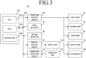
- FIG. 3 is a block diagram illustrating an example of an electrical configuration of the liquid chromatograph 10 of the present embodiment.
- the liquid chromatograph 10 includes a control unit 200, an operation control circuit 210, a display control circuit 212, a display unit 214, an operation detection circuit 216, an operation unit 218, and the like in addition to the first pump 26, the second pump 34, the first detector 48, the third pump 66, the fourth pump 74, the second detector 88, the autosampler 100, and the like.
- each of the first detector 48, the second detector 88, the control unit 200, the operation control circuit 210, the display control circuit 212, and the operation detection circuit 216 is electrically connected to each other via a wiring 208 such as a bus.
- the operation control circuit 210 is electrically connected to the first pump 26, the second pump 34, the third pump 66, the fourth pump 74, and the autosampler 100. Furthermore, the display control circuit 212 is electrically connected to the display unit 214, and the operation detection circuit 216 is electrically connected to the operation unit 218.
- the control unit 200 is responsible for overall control of the liquid chromatograph 10.
- the control unit 200 includes a central processing unit (CPU) 202.
- the control unit 200 includes a random access memory (RAM) 204 and a storage unit 206 that can be directly accessed by the CPU 202.
- CPU central processing unit
- RAM random access memory
- the CPU 202 controls each component of the liquid chromatograph 10.
- RAM 204 is used as a work area and a buffer area of the CPU 202.
- the storage unit 206 is a nonvolatile memory, and for example, a hard disc drive (HDD), a solid state drive (SSD), or the like is used as the storage unit 206.
- HDD hard disc drive
- SSD solid state drive
- the storage unit 206 stores a control program for controlling each component of the liquid chromatograph 10, execution data required for executing the control program, and the like. Note that the storage unit 206 may be configured to include the RAM 204.
- the operation control circuit 210 generates a voltage for driving the first pump 26, the second pump 34, the third pump 66, the fourth pump 74, the autosampler 100, and the like, and appropriately applies the voltage thereto.
- the display control circuit 212 includes a graphics processing unit (GPU), a video random access memory (VRAM), and the like, and the GPU generates a display image for displaying various screens on the display unit 214 in the VRAM under an instruction of the CPU 202 and outputs the generated display image to the display unit 214.
- GPU graphics processing unit
- VRAM video random access memory
- the display unit 214 is a general-purpose display device such as a liquid crystal display (LCD) or an electro-luminescence (EL) display.
- LCD liquid crystal display
- EL electro-luminescence
- the operation detection circuit 216 outputs a signal or data corresponding to the operation of the operation unit 218 to the control unit 200, specifically, the CPU 202.
- the operation unit 218 includes hardware keys (operation keys). Examples of the operation key include a power key and the like. In addition, the operation unit 218 includes an input device. Examples of the input device include a keyboard and a mouse.
- the input device may include a touch panel.
- the touch panel is provided on the display surface of the display unit 214. Further, the touch panel and the display unit 214 may be integrally formed.
- the dispensing step can be performed at an optional timing. For example, when a predetermined operation on the operation unit 218 is detected, the dispensing step is performed.
- the dispensing step is a step of suctioning and discharging the sample.
- the first mobile phase 54 is introduced into the first column 44 and the second mobile phase 94 is introduced into the second column 84.
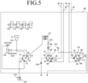
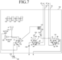
- FIGS. 4 to 7 are schematic views for explaining a dispensing step of the present embodiment. As illustrated in FIGS. 4 to 7 , a container 130 for containing a first sample 132 and a container 134 for containing a second sample 136 are set in advance in the autosampler 100.
- the second sample 136 is derivatized using a derivatization reagent 133 contained in the container 131.
- the derivatization reagent 133 is injected from the container 131 into the empty container 135, and the second sample 136 is injected from the container 134, whereby the derivatized second sample 137 is contained in the container 135.
- An example of derivatization includes fluorescent derivatization.
- the type of the derivatization reagent 133 is not particularly limited, and may be a mixture of a plurality of types (for example, two types) of derivatization reagents, or may be one type of derivatization reagent.
- the first sample 132 is not derivatized.
- the first suction operation for suctioning the first sample 132 is performed.
- the needle 124 is inserted into the container 130 as illustrated in FIG. 4 .
- the first switching valve 102, the second switching valve 110, and the third switching valve 116 are in the first state.
- the metering pump 120 is controlled, and the first sample 132 is introduced into the needle loop 122 via the needle 124.
- the first sample 132 introduced into the needle loop 122 is stored in the needle loop 122.
- a first discharge operation for discharging the first sample 132 is performed.
- the needle 124 is inserted into the first injection port 106 as illustrated in FIG. 5 .
- the first switching valve 102 is switched from the first state to the second state, and the third switching valve 116 is switched from the first state to the fourth state. Further, when the first discharge operation is performed, the on-off valve 108 is opened.
- the metering pump 120 is controlled, and the first sample 132 in the needle loop 122 is introduced into the first sample loop 104 via the first injection port 106.
- the on-off valve 108 is closed so that the first sample 132 in the first sample loop 104 does not flow out.
- the first sample 132 introduced into the first sample loop 104 is stored in the first sample loop 104.
- a washing operation for washing the needle 124 is performed.
- the third switching valve 116 is switched from the fourth state to the third state, so that the suction side of the metering pump 120 is connected to the container 126 via the port C3, the port C2, and the like, and the washing solution 128 in the container 126 is suctioned.
- the third switching valve 116 is switched from the third state to the second state, so that the blow-out side of the metering pump 120 is connected to the rinsing port 118 via the port C4, the port C 1, and the like, and the washing solution 128 is introduced into the rinsing port 118.
- the washing solution 128 is introduced into the rinsing port 118, the needle 124 is inserted into the rinsing port 118, and the needle 124 is cleaned.
- the first suction operation, the first discharge operation, and the washing operation as described above are performed after the derivatization reagent 133 and the second sample 136 are injected into the empty container 135, the derivatization of the second sample 136 can be efficiently performed using the time.
- a second suction operation for suctioning the derivatized second sample 137 is performed.
- the needle 124 is inserted into the container 135 as illustrated in FIG. 6 .
- the third switching valve 116 is switched from the second state to the first state.
- the metering pump 120 is controlled, and the derivatized second sample 137 is introduced into the needle loop 122 via the needle 124.
- the derivatized second sample 137 introduced into the needle loop 122 is stored in the needle loop 122.
- a second discharge operation for discharging the derivatized second sample 137 is performed.
- the needle 124 is inserted into the second injection port 114 as illustrated in FIG. 7 .
- the second switching valve 110 is switched from the first state to the second state, and the third switching valve 116 is switched from the first state to the fourth state.
- the metering pump 120 is controlled to introduce the derivatized second sample 137 in the needle loop 122 into the second sample loop 112 via the second injection port 114.
- the drainage passage is connected to the blow-out side of the metering pump 120 via the port B6, the port C4, and the like, and the port C3 connected to the suction side of the metering pump 120 is sealed.
- the derivatized second sample 137 introduced into the second sample loop 112 is stored in the second sample loop 112.
- the first analysis step is a step of introducing the first sample 132 into the first column 44 together with the first mobile phase 54 and analyzing components contained in the first sample 132.
- the second analysis step is a step of introducing the derivatized second sample 137 into the second column 84 together with the second mobile phase 94 and analyzing components contained in the second sample 137.
- "parallel" is not limited to a case where the first analysis step and the second analysis step are simultaneously started, and is a concept including a case where at least a part of the first analysis step and the second analysis step is simultaneously performed. Therefore, at least one of the start timing and the end timing of the first analysis step and the second analysis step may not be simultaneous.
- FIG. 8 is a schematic view for explaining the first analysis step and the second analysis step of the present embodiment.
- the first switching valve 102 and the second switching valve 110 are switched from the second state to the first state.
- the first switching valve 102 When the first switching valve 102 is switched from the second state to the first state, the first sample 132 in the first sample loop 104 is introduced into the first mobile phase 54 introduced from the piping 40. Therefore, the first sample 132 is introduced into the first column 44 together with the first mobile phase 54.
- the derivatized second sample 137 in the second sample loop 112 is introduced into the second mobile phase 94 introduced from the piping 80. Therefore, the derivatized second sample 137 is introduced into the second column 84 together with the second mobile phase 94.
- the first sample 132 passes through the first column 44, components in the first sample 132 are separated, and the separated components are detected by the first detector 48.
- the first detector 48 When each component is detected by the first detector 48, the first chromatogram is acquired based on the detection result.
- each component in the second sample 137 is separated, and each separated component is detected by the second detector 88.
- the second chromatogram is acquired based on the detection result.
- the introduction of the first mobile phase 54 into the first column 44 and the introduction of the second mobile phase 94 into the second column 84 are continued until both the first analysis step and the second analysis step are completed.
- the separation degree of each component in the first chromatogram changes according to the dimension and type of the first column 44
- the separation degree of each component in the second chromatogram changes according to the dimension and type of the second column 84.
- the configuration of the autosampler 100 is not particularly limited as long as the first analysis step and the second analysis step can be performed in parallel as described above.
- the first sample 132 may be introduced into the first column 44 along the total volume injection method
- the derivatized second sample 137 may be introduced into the second column 84 along the loop injection method.
- the freshness of food can be measured by analyzing ATP-related substances.
- the ATP-related substances include nucleic acid-related substances such as hypoxanthine (Hx), inosinic acid (IMP), inosine (HxR), adenosine monophosphate (AMP), adenosine diphosphate (ADP), and adenosine triphosphate (ATP).
- the first sample 132 contains at least inosinic acid (IMP) among the above-described six components of ATP-related substances.
- the first sample 132 contains guanylic acid (GMP), which is an example of a flavor component contained in food, in addition to the ATP-related substances.
- the first sample 132 is subjected to pretreatment.
- Food spoilage can be measured by analyzing histamine (Him).
- Other analytes may include specific amino acids known as nutritional components (including flavor components).
- specific amino acid include aspartic acid (Asp), glutamic acid (Glu), asparagine (Asn), serine (Ser), glutamine (Gln), glycine (Gly), histidine (His), threonine (Thr), ⁇ -alanine ( ⁇ -Ala), arginine (Arg), alanine (Ala), taurine (Tau), anserine (Ans), carnosine (Car), tyrosine (Tyr), valine (Val), methionine (Met), cystine ((Cys) 2 ), tryptophan (Trp), phenylalanine (Phe), isoleucine (Ile), leucine (Leu), lysine (Lys), and proline (Pro).
- the second sample 136 contains histamine (Him) and at least one
- the ODS column is a column in which a filler in which octadecylsilyl groups are chemically bonded to a silica gel carrier is packed.
- the first column 44 has an inner diameter of 3.0 mm, and the particle size of the particle to be separated is 3 pm.
- the second column 84 has an inner diameter of 3.0 mm, and the particle size of the particle to be separated is 2.7 pm.
- the flow rate of the first mobile phase 54 in the first column 44 was 0.8 mL/min, and the first column 44 was used in a state of being heated to 30°C. In addition, 5 ⁇ L of the first sample 132 was injected into the first mobile phase 54.
- As the first detector 48 a photodiode array detector having a measurement wavelength of 260 nm was used.
- the flow rate of the second mobile phase 94 in the second column 84 is 0.8 mL/min, which is the same as the flow rate of the first mobile phase 54 in the first column 44.
- the second column 84 was used in a state of being heated to 35°C.
- 1 ⁇ L of the derivatized second sample 137 was injected into the second mobile phase 94.
- a fluorescence detector was used. More specifically, as the fluorescence detector, a multichannel detector having a channel for detecting fluorescence of 450 nm at an excitation wavelength of 350 nm and a channel for detecting fluorescence of 305 nm at an excitation wavelength of 266 nm was used.
- the length of the second column 84 is 100 mm.
- the first column 44 having a length of 100 mm was used similarly to the second column 84, there was a peak that could not be separated with a sufficient separation degree in the obtained first chromatogram. Therefore, a case where the first column 44 having a length of 100 mm is used will be described below as a comparative example.
- FIG. 9 is a diagram illustrating a first chromatogram in a comparative example.
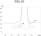
- FIG. 10 is an enlarged view of a part of the first chromatogram in FIG. 9 .
- FIG. 9 a plurality of peaks corresponding to the ATP-related substance and the like contained in the first sample 132 appear.
- the highest peak appearing in the vicinity of the retention time of 2.3 min is enlarged and illustrated in FIG. 10 .
- This peak can be divided into a peak corresponding to inosinic acid (IMP) and a peak corresponding to guanylic acid (GMP) as additionally illustrated in FIG. 10 . That is, in the first chromatogram, since the retention times of inosinic acid and guanylic acid are close, the peak corresponding to inosinic acid and the peak corresponding to guanylic acid cannot be sufficiently separated, and appear as one peak.
- IMP inosinic acid
- GMP guanylic acid
- Equation (1) the separation degree between the peak corresponding to inosinic acid and the peak corresponding to guanylic acid can be calculated using the following Equation (1).
- R represents a separation degree
- t 1 represents a retention time of guanylic acid
- t 2 represents retention time of inosinic acid
- W 1 represents a peak width of guanylic acid
- W 2 represents a peak width of inosinic acid.
- the separation degree between the peak corresponding to inosinic acid and the peak corresponding to guanylic acid was calculated using the above Equation (1), the separation degree was 1.1. That is, when a column having a length of 100 mm is used as the first column 44, the peak corresponding to inosinic acid and the peak corresponding to guanylic acid can hardly be separated. In addition, since inosinic acid and guanylic acid have the same detection wavelength, they cannot be separated by the wavelength.
- the peak corresponding to inosinic acid and the peak corresponding to guanylic acid are sufficiently separated using a column having a length equal to or longer than a predetermined threshold as the first column 44. That is, the separation degree between the peak corresponding to inosinic acid and the peak corresponding to guanylic acid is set to 1.5 or more.
- Equation (2) R is a separation degree
- N is a theoretical plate number
- a is a separation coefficient
- k is a retention coefficient
- the separation degree is proportional to the square root of the theoretical plate number. Therefore, if the separation degree is improved from R to R 1 , that is, if the separation degree is multiplied by R 1 / R, the theoretical plate number needs to be multiplied by ( R 1 2 )/( R 2 ).
- the length of the column is proportional to the theoretical plate number, if the length L of the column corresponding to the separation degree R is multiplied by ( R 1 2 )/( R 2 ) the length L 1 of the column required to obtain the separation degree R 1 is calculated. Therefore, the length L 1 of the column is expressed by the following Equation (3).
- the separation degree between the peak corresponding to inosinic acid and the peak corresponding to guanylic acid was 1.1 in the first chromatogram obtained using the first column 44.
- the separation degree required for sufficiently separating the peak corresponding to inosinic acid and the peak corresponding to guanylic acid is 1.5 or more.
- the length L 1 of the first column 44 necessary for obtaining the separation degree 1.5 is calculated to be 185 mm. Therefore, in the example, the length of the first column 44 is 185 mm or more.
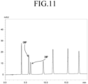
- FIG. 11 is a diagram illustrating a first chromatogram in example.
- FIG. 12 is a diagram illustrating another first chromatogram in example.
- the first chromatogram illustrated in FIG. 11 corresponds to a case where a mixed standard solution is separated by the first column 44
- the first chromatogram illustrated in FIG. 12 corresponds to a case where a sample extracted from tuna is separated by the first column 44.
- the standard solution herein is a solution obtained by mixing the same components as the components contained in the first sample 132 in the same amounts (50 ⁇ mol/L each).
- the peak corresponding to inosinic acid (IMP) and the peak corresponding to guanylic acid (GMP) are completely separated.
- the peak corresponding to inosinic acid (IMP) and the peak corresponding to guanylic acid (GMP) are completely separated although the peak heights are different.
- the separation degree between the peak corresponding to inosinic acid and the peak corresponding to guanylic acid was 1.9 as calculated using the above Equation (1).
- FIG. 13 is a diagram illustrating an example of UV spectra in the examples in FIGS. 11 and 12 .
- a spectrum Aof a peak corresponding to guanylic acid (GMP) having a retention time of about 5.7 min in the example of FIG. 11 and a spectrum B of a peak having a retention time of about 5.7 min in the example of FIG. 12 are shown on the same graph.
- the spectrum A and the spectrum B substantially coincide with each other. That is, in the first chromatogram illustrated in FIG. 11 , it is found that a peak having a retention time of about 5.7 min is a peak corresponding to guanylic acid.
- a gradient step is performed by controlling the drive of the first pump 26 and the second pump 34 during the first analysis step. That is, the first analysis step includes the gradient step.
- the mixing ratio of the first solution 50 and the second solution 52 is changed to gradually increase the ratio of the organic solvent in the first mobile phase 54.
- the first solution 50 is obtained by mixing water and acetonitrile at a volume ratio of 100: 1
- the second solution 52 is obtained by mixing water and acetonitrile at a volume ratio of 80: 20. Both the first solution 50 and the second solution 52 contain 0.15 mol/L of phosphoric acid and 0.225 mol/L of triethylamine.
- the ratio of the first solution 50 in the first mobile phase 54 is gradually reduced, and the ratio of the second solution 52 is gradually increased. Specifically, only the first solution 50 is introduced as the first mobile phase 54 until 5 minutes elapse from the start of the first analysis step, and thereafter, the ratio of the second solution 52 in the first mobile phase 54 is gradually increased. As a result, when 19 minutes have elapsed from the start of the first analysis step, the ratio of the second solution 52 in the first mobile phase 54 becomes 24%.
- the first mobile phase 54 can be introduced into the first column 44 by increasing the content ratio of the organic solvent in the second solution 52 and increasing the ratio of the second solution 52 with a high gradient as described above.
- the gradient step is performed by controlling the drive of the third pump 66 and the fourth pump 74. That is, the second analysis step includes a gradient step. In the gradient step, the mixing ratio of the third solution 90 and the fourth solution 92 is changed to gradually increase the ratio of the organic solvent in the second mobile phase 94.
- the third solution 90 is a phosphate buffer having a pH of 6.5 containing 20 mmol/L of phosphate
- the fourth solution 92 is obtained by mixing acetonitrile, methanol, and water at a volume ratio of 45: 40: 15.
- the ratio of the third solution 90 in the second mobile phase 94 is gradually reduced, and the ratio of the fourth solution 92 is gradually increased. Specifically, until 8 minutes elapse from the start of the second analysis step, the ratio of the fourth solution 92 in the second mobile phase 94 is gradually increased from 5% to 13%. Thereafter, the ratio of the fourth solution 92 in the second mobile phase 94 is gradually increased from 13% to 25% until 15 minutes elapse from the start of the second analysis step. Thereafter, the ratio of the fourth solution 92 in the second mobile phase 94 is gradually increased from 25% to 52% until 21.5 minutes elapse from the start of the second analysis step.
- the time until the elution of each component is completed can be shortened without deteriorating the separation degree at the peak of the component having a short retention time among the components contained in the first sample 132 or the derivatized second sample 137. That is, it is possible to suppress the time until the elution of each component contained in the first sample 132 or the derivatized second sample 137 is completed from becoming longer as the length of the first column 44 or the second column 84 becomes longer.
- the first analysis step and the second analysis step include a washing step.
- the washing step is performed after the gradient step.
- the washing step in the first analysis step is a step of introducing only the second solution 52 as the first mobile phase 54 into the first column 44 and washing the inside of the first column 44 for 19.10 min to 25.00 min from the start of the first analysis step. Thereafter, only the first solution 50 is introduced into the first column 44 as the first mobile phase 54 for 25.10 min to 32.00 min from the start of the first analysis step.
- the washing step in the second analysis step is a step of introducing only the fourth solution 92 as the second mobile phase 94 into the second column 84 and washing the inside of the second column 84 for 21.51 min to 27.50 min from the start of the second analysis step. Thereafter, only the third solution 90 is introduced into the second column 84 as the second mobile phase 94 for 27.51 min to 32.00 min from the start of the second analysis step.
- the washing step since contaminants are not accumulated in the first column 44 or the second column 84, it is possible to suppress an increase in load on the first column 44 or the second column 84. That is, deterioration of the first column 44 or the second column 84 can be suppressed.
- the first column 44 having a length of 185 mm or more can be sufficiently washed by performing the washing step during the first analysis step over a relatively long time before both the first analysis step and the second analysis step are completed.
- FIG. 14 is a block diagram specifically illustrating an electrical configuration of the liquid chromatograph 10 of the present embodiment.
- the storage unit 206 is not illustrated.
- the RAM 204 stores execution data read in advance from the storage unit 206.
- execution data read in advance from the storage unit 206.
- the acquired data is temporarily stored in the RAM 204.
- the RAM 204 stores control data 220, first chromatogram data 222, second chromatogram data 224, display image data 226, and operation data 228.
- the control data 220 is various data necessary for controlling the operation in the liquid chromatograph 10.
- the first chromatogram data 222 is data corresponding to the first chromatogram.
- the second chromatogram data 224 is data corresponding to the second chromatogram.
- the display image data 226 is data corresponding to the display image.
- the operation data 228 is data representing an operation state of the operation unit 218.
- a control program read in advance from the storage unit 206 is stored in the RAM 204, and when the CPU 202 executes the control program, the control unit 200 functions as a dispensing processing unit 230, a first analysis processing unit 232, a second analysis processing unit 238, a first acquisition processing unit 240, a second acquisition processing unit 242, a display processing unit 244, and an operation detection processing unit 246.
- the first analysis processing unit 232 includes a gradient processing unit 234 and a washing processing unit 236.
- the second analysis processing unit 238 also includes a gradient processing unit and a washing processing unit.
- the dispensing processing unit 230 controls the autosampler 100 using the control data 220 to perform the dispensing step.
- the first analysis processing unit 232 performs the first analysis step by controlling the first pump 26, the second pump 34, and the autosampler 100 using the control data 220.
- the gradient processing unit 234 performs a gradient step by controlling the first pump 26 and the second pump 34 using the control data 220. After the gradient step is performed, the washing processing unit 236 controls the second pump 34 using the control data 220 to perform the washing step.
- the second analysis processing unit 238 controls the third pump 66, the fourth pump 74, and the autosampler 100 to perform the second analysis step.
- the first acquisition processing unit 240 acquires the first chromatogram data 222 based on the signal from the first detector 48 and stores the first chromatogram data 222 in the RAM 204.
- the second acquisition processing unit 242 acquires the second chromatogram data 224 based on the signal from the second detector 88 and stores the second chromatogram data in the RAM 204.
- the display processing unit 244 outputs the display image data 226 to the display unit 214.
- the operation detection processing unit 246 detects an operation on the operation unit 218 and stores the operation data 228 in the RAM 204 in chronological order.
- An analytical method is an analytical method for performing, in parallel, a first analysis step of introducing a non-derivatized first sample into a first column together with a first mobile phase, and analyzing components contained in the first sample, and a second analysis step of introducing a derivatized second sample into the second column together with a second mobile phase, and analyzing components contained in the second sample, using a first column and a second column each constituted by an ODS column, wherein the first sample may contain inosinic acid and guanylic acid, and in the first analysis step, by separating components contained in the first sample using the first column having a length of 185 mm or more, a chromatogram may be obtained in which peaks corresponding to inosinic acid and guanylic acid are separated with a separation degree of 1.5 or more.
- the analytical method described in Aspect 1 it is possible to acquire a chromatogram in which peaks corresponding to inosinic acid and guanylic acid contained in the first sample are sufficiently separated while analyzing components contained in each of the non-derivatized first sample and the derivatized second sample in parallel. That is, the peak corresponding to guanylic acid, which is an example of a flavor component contained in food, can be separated from the peak corresponding to inosinic acid without separately providing a column.
- Aspect 2 The analytical method according to Aspect 1, wherein the first analysis step may include a gradient step of gradually increasing a ratio of an organic solvent in the first mobile phase to be introduced into the first column by changing a mixing ratio between the first solution and the second solution having a higher organic solvent content ratio than that of the first solution.
- Aspect 3 The analytical method according to Aspect 2, wherein the first analysis step may include a washing step of washing the inside of the first column by introducing only the second solution into the first column after the gradient step.
- the first column can be sufficiently washed by performing the washing step during the first analysis step over a relatively long time before both the first analysis step and the second analysis step are completed.
Landscapes
- Chemical & Material Sciences (AREA)
- Analytical Chemistry (AREA)
- Health & Medical Sciences (AREA)
- Life Sciences & Earth Sciences (AREA)
- Biochemistry (AREA)
- Physics & Mathematics (AREA)
- General Health & Medical Sciences (AREA)
- General Physics & Mathematics (AREA)
- Immunology (AREA)
- Pathology (AREA)
- Food Science & Technology (AREA)
- Engineering & Computer Science (AREA)
- Medicinal Chemistry (AREA)
- Organic Chemistry (AREA)
- Chemical Kinetics & Catalysis (AREA)
- Sampling And Sample Adjustment (AREA)
Abstract
Description
- The present invention relates to an analytical method.
- For example, a liquid chromatograph disclosed in Patent Document 1 below is configured to be able to simultaneously execute analysis processing using a plurality of columns.
- Patent Document 1:
WO 2020/183663 A - The inventor of the present application has studied performing analysis using the liquid chromatograph as described above in order to analyze both freshness and spoilage of food such as meat (including fish) in a short time. The freshness of food can be measured by analyzing ATP-related substances including inosinic acid. Meanwhile, food spoilage can be measured by analyzing histamine. When specific amino acids (hereinafter, it is referred to as "histamine/amino acid") including histamine and glutamic acid are analyzed, they are derivatized and then detected by a detector.
- When both ATP-related substances and histamine/amino acids are analyzed, it is necessary to analyze ATP-related substances that are not derivatized and histamine/amino acids that are derivatized in different analysis systems. In this case, it is conceivable to prepare an analysis device for analyzing ATP-related substances and an analysis device for analyzing histamine and amino acids, but there arises a problem of installation space of the device and the like. Therefore, it is conceivable to analyze ATP-related substances on one of the two columns and to analyze histamine and amino acids on the other column using the liquid chromatograph as described above.
- In the course of such studies, the inventors of the present application have attempted to analyze guanylic acid, which is an example of a flavor component, together with inosinic acid and guanylic acid contained in food simultaneously with an ATP-related substance and histamine/amino acid. In this case, it is conceivable to separately provide a column for analyzing guanylic acid and perform analysis on three columns, but it is efficient to perform analysis using the same column as the ATP-related substance that is not derivatized.
- However, inosinic acid contained in ATP-related substances has a retention time close to that of guanylic acid. Therefore, it has been found that it is difficult to acquire a chromatogram in which peaks corresponding to inosinic acid and guanylic acid are separated.
- The present invention has been made in view of the above circumstances, and an object thereof is to provide an analytical method capable of separating peaks corresponding to inosinic acid and guanylic acid contained in a first sample when analyzing components contained in each of a non-derivatized first sample and a derivatized second sample in parallel.
- A first aspect of the present invention is an analytical method for performing, in parallel, a first analysis step of introducing a non-derivatized first sample into a first column together with a first mobile phase, and analyzing components contained in the first sample, and a second analysis step of introducing a derivatized second sample into a second column together with a second mobile phase, and analyzing components contained in the second sample, using the first column and the second column each constituted by an ODS column, wherein the first sample contains inosinic acid and guanylic acid, and in the first analysis step, by separating components contained in the first sample using the first column having a length of 185 mm or more, a chromatogram is obtained in which peaks corresponding to inosinic acid and guanylic acid are separated with a separation degree of 1.5 or more.
- According to the present invention, when components contained in each of the non-derivatized first sample and the derivatized second sample are analyzed in parallel, peaks corresponding to inosinic acid and guanylic acid contained in the first sample can be separated.
-
-
FIG. 1 is a block diagram illustrating an example of a configuration of a liquid chromatograph of the present embodiment. -
FIG. 2 is a schematic view illustrating an example of a configuration of an autosampler of the present embodiment. -
FIG. 3 is a block diagram illustrating an example of an electrical configuration of a liquid chromatograph of the present embodiment. -
FIG. 4 is a schematic view for explaining a dispensing step of the present embodiment. -
FIG. 5 is a schematic view for explaining the dispensing step of the present embodiment. -
FIG. 6 is a schematic view for explaining the dispensing step of the present embodiment. -
FIG. 7 is a schematic view for explaining the dispensing step of the present embodiment. -
FIG. 8 is a schematic view for explaining a first analysis step and a second analysis step of the present embodiment. -
FIG. 9 is a diagram illustrating a first chromatogram in a comparative example. -
FIG. 10 is an enlarged view illustrating a part of the first chromatogram inFIG. 9 . -
FIG. 11 is a diagram illustrating the first chromatogram in examples. -
FIG. 12 is a diagram illustrating another first chromatogram in examples. -
FIG. 13 is a diagram illustrating an example of UV spectra in examples corresponding toFIGS. 11 and12 . -
FIG. 14 is a block diagram specifically illustrating an electrical configuration of a liquid chromatograph of the present embodiment. -
FIG. 1 is a block diagram illustrating an example of a configuration of aliquid chromatograph 10 of the present embodiment. As illustrated inFIG. 1 , theliquid chromatograph 10 includes afirst analysis system 20 and asecond analysis system 60. - The
first analysis system 20 includes a container 22, apiping 24, afirst pump 26, apiping 28, acontainer 30, apiping 32, asecond pump 34, apiping 36, afirst mixer 38, apiping 40, afirst switching valve 102, apiping 42, afirst column 44, apiping 46, afirst detector 48, and the like. - The
second analysis system 60 includes acontainer 62, apiping 64, athird pump 66, apiping 68, acontainer 70, apiping 72, afourth pump 74, apiping 76, asecond mixer 78, apiping 80, asecond switching valve 110, apiping 82, asecond column 84, apiping 86, asecond detector 88, and the like. - In the
first analysis system 20, an upstream end of thepiping 24 is inserted into the container 22, and a downstream end is connected to thefirst pump 26. The upstream end of thepiping 28 is connected to thefirst pump 26, and the downstream end is connected to thefirst mixer 38. - The upstream end of the
piping 32 is inserted into thecontainer 30, and the downstream end is connected to thesecond pump 34. The upstream end of thepiping 36 is connected to thesecond pump 34, and the downstream end is connected to thefirst mixer 38. - The upstream end of the
piping 40 is connected to thefirst mixer 38, and the downstream end is connected to thefirst switching valve 102. The upstream end of thepiping 42 is connected to thefirst switching valve 102, and the downstream end is connected to thefirst column 44. The upstream end of thepiping 46 is connected to thefirst column 44, and the downstream end is connected to thefirst detector 48. - In addition, the
first solution 50 is contained in the container 22, and thesecond solution 52 is contained in thecontainer 30. Specifically, thefirst solution 50 and thesecond solution 52 are solvents constituting a mobile phase, and thesecond solution 52 has a higher content ratio of the organic solvent than that of thefirst solution 50. - In the
second analysis system 60, the upstream end of thepiping 64 is inserted into thecontainer 62, and the downstream end is connected to thethird pump 66. The upstream end of thepiping 68 is connected to thethird pump 66, and the downstream end is connected to thesecond mixer 78. - The upstream end of the
piping 72 is inserted into thecontainer 70, and the downstream end is connected to thefourth pump 74. The upstream end of thepiping 76 is connected to thefourth pump 74, and the downstream end is connected to thesecond mixer 78. - The upstream end of the
piping 80 is connected to thesecond mixer 78, and the downstream end is connected to thesecond switching valve 110. The upstream end of thepiping 82 is connected to thesecond switching valve 110, and the downstream end is connected to thesecond column 84. The upstream end of thepiping 86 is connected to thesecond column 84, and the downstream end is connected to thesecond detector 88. - In addition, a
third solution 90 is contained in thecontainer 62, and afourth solution 92 is contained in thecontainer 70. Specifically, thethird solution 90 and thefourth solution 92 are solvents constituting the mobile phase, and thefourth solution 92 has a higher content ratio of the organic solvent than thethird solution 90. - The
first switching valve 102 and thesecond switching valve 110 constitute a part of anautosampler 100. Theautosampler 100 is shared by thefirst analysis system 20 and thesecond analysis system 60. - In the
first analysis system 20, for example, when thefirst pump 26 and thesecond pump 34 are driven, thefirst solution 50 and thesecond solution 52 are mixed by thefirst mixer 38 to generate the firstmobile phase 54, and the firstmobile phase 54 is led out from thefirst mixer 38 to thepiping 40. That is, in this case, the firstmobile phase 54 includes thefirst solution 50 and thesecond solution 52. - For example, when only the
first pump 26 is driven, thesecond solution 52 is not introduced into thefirst mixer 38, so that the firstmobile phase 54 containing only thefirst solution 50 is led out from thefirst mixer 38 to thepiping 40. - Furthermore, when only the
second pump 34 is driven, thefirst solution 50 is not introduced into thefirst mixer 38, so that the firstmobile phase 54 containing only thesecond solution 52 is led out from thefirst mixer 38 to thepiping 40. - Therefore, in the
first analysis system 20, by appropriately driving thefirst pump 26 and thesecond pump 34 and adjusting the flow rates of thefirst solution 50 and thesecond solution 52, the mixing ratio of thefirst solution 50 and thesecond solution 52 in the firstmobile phase 54 can be adjusted to perform gradient analysis. - In addition, a sample is injected into the first
mobile phase 54 using thefirst switching valve 102 of theautosampler 100. Furthermore, the firstmobile phase 54 into which the sample is injected is introduced into thefirst detector 48 after passing through thefirst column 44, whereby a chromatogram including peaks corresponding to respective components in the sample separated in the process of passing through thefirst column 44 is acquired. - In the
second analysis system 60, similarly to thefirst analysis system 20, by appropriately driving thethird pump 66 and thefourth pump 74, it is possible to perform gradient analysis by adjusting the mixing ratio of thethird solution 90 and thefourth solution 92. The secondmobile phase 94 in which the mixing ratio of thethird solution 90 and thefourth solution 92 is adjusted is led out from thesecond mixer 78 to thepiping 80. - In addition, a sample is injected into the second
mobile phase 94 using thesecond switching valve 110 of theautosampler 100. Furthermore, the secondmobile phase 94 into which the sample is injected is introduced into thesecond detector 88 after passing through thesecond column 84, whereby a chromatogram including peaks corresponding to the respective components in the sample separated in the process of passing through thesecond column 84 is acquired. -
FIG. 2 is a schematic view illustrating an example of a configuration of theautosampler 100 of the present embodiment. As illustrated inFIG. 2 , in addition to thefirst switching valve 102 and thesecond switching valve 110 described above, theautosampler 100 includes afirst sample loop 104, afirst injection port 106, an on-offvalve 108, asecond sample loop 112, asecond injection port 114, athird switching valve 116, a rinsingport 118, ametering pump 120, aneedle loop 122, aneedle 124, and the like. - The
first switching valve 102 is a six-way valve having six ports A1 to A6. The port A1 is connected to thefirst injection port 106. The port A2 is connected to the on-offvalve 108. The port A3 is connected to the port A6 via thefirst sample loop 104. The port A4 is connected to thepiping 40. The port A5 is connected to thepiping 42. - Further, the rotor seal (not illustrated) of the
first switching valve 102 has three passages that connect adjacent ports to each other. Thefirst switching valve 102 is switched between the first state and the second state by the rotation of the rotor seal. The first state and the second state are different from each other in a combination of ports connected to each other. - When the
first switching valve 102 is in the first state, as illustrated inFIG. 2 , the port A1 and the port A2 are connected, the port A3 and the port A4 are connected, and the port A5 and the port A6 are connected. - That is, when the
first switching valve 102 is in the first state, the piping 40 is connected to the piping 42 via the port A4, the port A3, thefirst sample loop 104, the port A6, the port A5, and the like. Thefirst injection port 106 is connected to the on-offvalve 108 via the port A1, the port A2, and the like. - On the other hand, when the
first switching valve 102 is in the second state, the port A2 and the port A3 are connected, the port A4 and the port A5 are connected, and the port A6 and the port A1 are connected. - That is, when the
first switching valve 102 is in the second state (refer toFIG. 5 ), the piping 40 is connected to the piping 42 via the port A4, the port A5, and the like. In addition, thefirst injection port 106 is connected to the on-offvalve 108 via the portAl, the port A6, thefirst sample loop 104, the port A3, the port A2, and the like. - The
second switching valve 110 is a six-way valve having six ports B1 to B6. The port B1 is connected to the port B4 via thesecond sample loop 112. The port B2 is connected to thepiping 80. The port B3 is connected to thepiping 82. The port B5 is connected to thesecond injection port 114. The port B6 is connected to the drainage passage. - Further, the rotor seal (not illustrated) of the
second switching valve 110 has three passages connecting adjacent ports to each other, and is switched between the first state and the second state by the rotation of the rotor seal, similarly to thefirst switching valve 102. - When the
second switching valve 110 is in the first state, as illustrated inFIG. 2 , the port B1 and the port B2 are connected, the port B3 and the port B4 are connected, and the port B5 and the port B6 are connected. - That is, when the
second switching valve 110 is in the first state, the piping 80 is connected to the piping 82 via the port B2, the port B1, thesecond sample loop 112, the port B4, the port B3, and the like. Thesecond injection port 114 is connected to the drainage passage via the port B5, the port B6, and the like. - On the other hand, when the
second switching valve 110 is in the second state (refer toFIG. 7 ), the port B2 and the port B3 are connected, the port B4 and the port B5 are connected, and the port B6 and the port B1 are connected. - That is, when the
second switching valve 110 is in the second state, the piping 80 is connected to the piping 82 via the port B2, the port B3, and the like. In addition, thesecond injection port 114 is connected to the drainage passage via the port B5, the port B4, thesecond sample loop 112, the port B1, the port B6, and the like. - The
third switching valve 116 is a rotary valve having five ports C1 to C5. The port C 1 is connected to the rinsingport 118. The port C2 is disposed outside theautosampler 100 and connected to acontainer 126 that contains thewashing solution 128. The port C3 is connected to the suction side of themetering pump 120. The port C4 is connected to the blow-out side of themetering pump 120. The port C5 is connected to theneedle 124 via theneedle loop 122. - The rotor seal (not illustrated) of the
third switching valve 116 has a passage that connects any one of the port C1, the port C2, the port C3, and the port C4 to the port C5, and a passage that connects adjacent ports to each other. - The
third switching valve 116 can be switched to the first state, the second state, the third state, the fourth state, the fifth state, or the sixth state by the rotation of the rotor seal, and the combination of the ports connected to each other is different in each of the first state to the sixth state. - When the
third switching valve 116 is in the first state, the port C3 and the port C5 are connected as illustrated inFIG. 2 . That is, when thethird switching valve 116 is in the first state, the suction side of themetering pump 120 is connected to theneedle 124 via the port C3, the port C5, theneedle loop 122, and the like. - When the
third switching valve 116 is in the second state, the port C4 and the port C1 are connected. That is, when thethird switching valve 116 is in the second state, the blow-out side of themetering pump 120 is connected to the rinsingport 118 via the port C4, the port C 1, and the like. - When the
third switching valve 116 is in the third state, the port C2 and the port C3 are connected. That is, when thethird switching valve 116 is in the third state, the suction side of themetering pump 120 is connected to thecontainer 126 via the port C3, the port C2, and the like. - When the
third switching valve 116 is in the fourth state (refer toFIG. 5 ), the port C4 and the port C5 are connected. That is, when thethird switching valve 116 is in the fourth state, the blow-out side of themetering pump 120 is connected to theneedle 124 via the port C4, the port C5, theneedle loop 122, and the like. - When the
third switching valve 116 is in the fifth state, the port C 1 and the port C5 are connected. That is, when thethird switching valve 116 is in the fifth state, the rinsingport 118 is connected to theneedle 124 via the port C 1, the port C5, theneedle loop 122, and the like. - When the
third switching valve 116 is in the sixth state, the port C2 and the port C5 are connected. That is, when thethird switching valve 116 is in the sixth state, thecontainer 126 is connected to theneedle 124 via the port C2, the port C5, theneedle loop 122, and the like. - Although not illustrated, the
autosampler 100 movably supports theneedle 124 and includes an electrically controllable moving mechanism. Thefirst switching valve 102, the on-offvalve 108, thesecond switching valve 110, thethird switching valve 116, themetering pump 120, and the like can be electrically controlled. -
FIG. 3 is a block diagram illustrating an example of an electrical configuration of theliquid chromatograph 10 of the present embodiment. As illustrated inFIG. 3 , theliquid chromatograph 10 includes acontrol unit 200, anoperation control circuit 210, adisplay control circuit 212, adisplay unit 214, anoperation detection circuit 216, anoperation unit 218, and the like in addition to thefirst pump 26, thesecond pump 34, thefirst detector 48, thethird pump 66, thefourth pump 74, thesecond detector 88, theautosampler 100, and the like. - In addition, each of the
first detector 48, thesecond detector 88, thecontrol unit 200, theoperation control circuit 210, thedisplay control circuit 212, and theoperation detection circuit 216 is electrically connected to each other via awiring 208 such as a bus. - Further, the
operation control circuit 210 is electrically connected to thefirst pump 26, thesecond pump 34, thethird pump 66, thefourth pump 74, and theautosampler 100. Furthermore, thedisplay control circuit 212 is electrically connected to thedisplay unit 214, and theoperation detection circuit 216 is electrically connected to theoperation unit 218. - The
control unit 200 is responsible for overall control of theliquid chromatograph 10. Thecontrol unit 200 includes a central processing unit (CPU) 202. In addition, thecontrol unit 200 includes a random access memory (RAM) 204 and astorage unit 206 that can be directly accessed by theCPU 202. - The
CPU 202 controls each component of theliquid chromatograph 10.RAM 204 is used as a work area and a buffer area of theCPU 202. Thestorage unit 206 is a nonvolatile memory, and for example, a hard disc drive (HDD), a solid state drive (SSD), or the like is used as thestorage unit 206. - The
storage unit 206 stores a control program for controlling each component of theliquid chromatograph 10, execution data required for executing the control program, and the like. Note that thestorage unit 206 may be configured to include theRAM 204. - The
operation control circuit 210 generates a voltage for driving thefirst pump 26, thesecond pump 34, thethird pump 66, thefourth pump 74, theautosampler 100, and the like, and appropriately applies the voltage thereto. - The
display control circuit 212 includes a graphics processing unit (GPU), a video random access memory (VRAM), and the like, and the GPU generates a display image for displaying various screens on thedisplay unit 214 in the VRAM under an instruction of theCPU 202 and outputs the generated display image to thedisplay unit 214. - The
display unit 214 is a general-purpose display device such as a liquid crystal display (LCD) or an electro-luminescence (EL) display. - The
operation detection circuit 216 outputs a signal or data corresponding to the operation of theoperation unit 218 to thecontrol unit 200, specifically, theCPU 202. - The
operation unit 218 includes hardware keys (operation keys). Examples of the operation key include a power key and the like. In addition, theoperation unit 218 includes an input device. Examples of the input device include a keyboard and a mouse. - Furthermore, the input device may include a touch panel. In this case, the touch panel is provided on the display surface of the
display unit 214. Further, the touch panel and thedisplay unit 214 may be integrally formed. - In such a
liquid chromatograph 10, the dispensing step can be performed at an optional timing. For example, when a predetermined operation on theoperation unit 218 is detected, the dispensing step is performed. - The dispensing step is a step of suctioning and discharging the sample. In the present embodiment, during the dispensing step, the first
mobile phase 54 is introduced into thefirst column 44 and the secondmobile phase 94 is introduced into thesecond column 84. -
FIGS. 4 to 7 are schematic views for explaining a dispensing step of the present embodiment. As illustrated inFIGS. 4 to 7 , acontainer 130 for containing afirst sample 132 and acontainer 134 for containing asecond sample 136 are set in advance in theautosampler 100. - In the present embodiment, the
second sample 136 is derivatized using aderivatization reagent 133 contained in thecontainer 131. Specifically, thederivatization reagent 133 is injected from thecontainer 131 into theempty container 135, and thesecond sample 136 is injected from thecontainer 134, whereby the derivatizedsecond sample 137 is contained in thecontainer 135. An example of derivatization includes fluorescent derivatization. The type of thederivatization reagent 133 is not particularly limited, and may be a mixture of a plurality of types (for example, two types) of derivatization reagents, or may be one type of derivatization reagent. On the other hand, thefirst sample 132 is not derivatized. - After the derivatization of the
second sample 136 is started as described above, the first suction operation for suctioning thefirst sample 132 is performed. When the first suction operation is performed, theneedle 124 is inserted into thecontainer 130 as illustrated inFIG. 4 . When the first suction operation is performed, thefirst switching valve 102, thesecond switching valve 110, and thethird switching valve 116 are in the first state. - In the first suction operation, the
metering pump 120 is controlled, and thefirst sample 132 is introduced into theneedle loop 122 via theneedle 124. Thefirst sample 132 introduced into theneedle loop 122 is stored in theneedle loop 122. - After the first suction operation is performed, a first discharge operation for discharging the
first sample 132 is performed. When the first discharge operation is performed, theneedle 124 is inserted into thefirst injection port 106 as illustrated inFIG. 5 . When the first discharge operation is performed, thefirst switching valve 102 is switched from the first state to the second state, and thethird switching valve 116 is switched from the first state to the fourth state. Further, when the first discharge operation is performed, the on-offvalve 108 is opened. - In the first discharge operation, the
metering pump 120 is controlled, and thefirst sample 132 in theneedle loop 122 is introduced into thefirst sample loop 104 via thefirst injection port 106. When the first discharge operation is performed, the on-offvalve 108 is closed so that thefirst sample 132 in thefirst sample loop 104 does not flow out. Thefirst sample 132 introduced into thefirst sample loop 104 is stored in thefirst sample loop 104. - After the first discharge operation is performed, a washing operation for washing the
needle 124 is performed. Although not illustrated, when the washing operation is started, thethird switching valve 116 is switched from the fourth state to the third state, so that the suction side of themetering pump 120 is connected to thecontainer 126 via the port C3, the port C2, and the like, and thewashing solution 128 in thecontainer 126 is suctioned. - When the
washing solution 128 in thecontainer 126 is suctioned, thethird switching valve 116 is switched from the third state to the second state, so that the blow-out side of themetering pump 120 is connected to the rinsingport 118 via the port C4, the port C 1, and the like, and thewashing solution 128 is introduced into the rinsingport 118. - Further, when the
washing solution 128 is introduced into the rinsingport 118, theneedle 124 is inserted into the rinsingport 118, and theneedle 124 is cleaned. In the present embodiment, since the first suction operation, the first discharge operation, and the washing operation as described above are performed after thederivatization reagent 133 and thesecond sample 136 are injected into theempty container 135, the derivatization of thesecond sample 136 can be efficiently performed using the time. - When the washing operation is performed in this manner, next, a second suction operation for suctioning the derivatized
second sample 137 is performed. When the second suction operation is performed, theneedle 124 is inserted into thecontainer 135 as illustrated inFIG. 6 . When the second suction operation is performed, thethird switching valve 116 is switched from the second state to the first state. - In the second suction operation, the
metering pump 120 is controlled, and the derivatizedsecond sample 137 is introduced into theneedle loop 122 via theneedle 124. The derivatizedsecond sample 137 introduced into theneedle loop 122 is stored in theneedle loop 122. - After the second suction operation is performed, a second discharge operation for discharging the derivatized
second sample 137 is performed. When the second discharge operation is performed, theneedle 124 is inserted into thesecond injection port 114 as illustrated inFIG. 7 . When the second discharge operation is performed, thesecond switching valve 110 is switched from the first state to the second state, and thethird switching valve 116 is switched from the first state to the fourth state. - In the second discharge operation, the
metering pump 120 is controlled to introduce the derivatizedsecond sample 137 in theneedle loop 122 into thesecond sample loop 112 via thesecond injection port 114. At this time, the drainage passage is connected to the blow-out side of themetering pump 120 via the port B6, the port C4, and the like, and the port C3 connected to the suction side of themetering pump 120 is sealed. As a result, the derivatizedsecond sample 137 introduced into thesecond sample loop 112 is stored in thesecond sample loop 112. - In the present embodiment, after the dispensing step is performed in this manner, the first analysis step and the second analysis step are performed in parallel. The first analysis step is a step of introducing the
first sample 132 into thefirst column 44 together with the firstmobile phase 54 and analyzing components contained in thefirst sample 132. The second analysis step is a step of introducing the derivatizedsecond sample 137 into thesecond column 84 together with the secondmobile phase 94 and analyzing components contained in thesecond sample 137. Note that "parallel" is not limited to a case where the first analysis step and the second analysis step are simultaneously started, and is a concept including a case where at least a part of the first analysis step and the second analysis step is simultaneously performed. Therefore, at least one of the start timing and the end timing of the first analysis step and the second analysis step may not be simultaneous. -
FIG. 8 is a schematic view for explaining the first analysis step and the second analysis step of the present embodiment. When the first analysis step and the second analysis step are performed, as illustrated inFIG. 8 , thefirst switching valve 102 and thesecond switching valve 110 are switched from the second state to the first state. - When the
first switching valve 102 is switched from the second state to the first state, thefirst sample 132 in thefirst sample loop 104 is introduced into the firstmobile phase 54 introduced from thepiping 40. Therefore, thefirst sample 132 is introduced into thefirst column 44 together with the firstmobile phase 54. - When the
second switching valve 110 is switched from the second state to the first state, the derivatizedsecond sample 137 in thesecond sample loop 112 is introduced into the secondmobile phase 94 introduced from thepiping 80. Therefore, the derivatizedsecond sample 137 is introduced into thesecond column 84 together with the secondmobile phase 94. - When the
first sample 132 passes through thefirst column 44, components in thefirst sample 132 are separated, and the separated components are detected by thefirst detector 48. When each component is detected by thefirst detector 48, the first chromatogram is acquired based on the detection result. - On the other hand, when the derivatized
second sample 137 passes through thesecond column 84, each component in thesecond sample 137 is separated, and each separated component is detected by thesecond detector 88. When each component is detected by thesecond detector 88, the second chromatogram is acquired based on the detection result. - The introduction of the first
mobile phase 54 into thefirst column 44 and the introduction of the secondmobile phase 94 into thesecond column 84 are continued until both the first analysis step and the second analysis step are completed. In addition, the separation degree of each component in the first chromatogram changes according to the dimension and type of thefirst column 44, and the separation degree of each component in the second chromatogram changes according to the dimension and type of thesecond column 84. - Furthermore, the configuration of the
autosampler 100 is not particularly limited as long as the first analysis step and the second analysis step can be performed in parallel as described above. For example, thefirst sample 132 may be introduced into thefirst column 44 along the total volume injection method, and the derivatizedsecond sample 137 may be introduced into thesecond column 84 along the loop injection method. - Hereinafter, an example in which the
first sample 132 and thesecond sample 136 are analyzed using theliquid chromatograph 10 as described above will be described. In this example, analysis conditions in a case where both freshness and spoilage of food such as meat (including fish) are analyzed by oneliquid chromatograph 10, and a flavor component contained in the food is also simultaneously analyzed by theliquid chromatograph 10 were examined. - The freshness of food can be measured by analyzing ATP-related substances. The ATP-related substances include nucleic acid-related substances such as hypoxanthine (Hx), inosinic acid (IMP), inosine (HxR), adenosine monophosphate (AMP), adenosine diphosphate (ADP), and adenosine triphosphate (ATP). The
first sample 132 contains at least inosinic acid (IMP) among the above-described six components of ATP-related substances. In addition, thefirst sample 132 contains guanylic acid (GMP), which is an example of a flavor component contained in food, in addition to the ATP-related substances. Thefirst sample 132 is subjected to pretreatment. - Food spoilage can be measured by analyzing histamine (Him). Other analytes may include specific amino acids known as nutritional components (including flavor components). Specifically, examples of the specific amino acid include aspartic acid (Asp), glutamic acid (Glu), asparagine (Asn), serine (Ser), glutamine (Gln), glycine (Gly), histidine (His), threonine (Thr), β-alanine (β-Ala), arginine (Arg), alanine (Ala), taurine (Tau), anserine (Ans), carnosine (Car), tyrosine (Tyr), valine (Val), methionine (Met), cystine ((Cys)2), tryptophan (Trp), phenylalanine (Phe), isoleucine (Ile), leucine (Leu), lysine (Lys), and proline (Pro). The
second sample 136 contains histamine (Him) and at least one of the 24 specific amino acids. Thesecond sample 136 is subjected to pretreatment. The pretreatment performed on thesecond sample 136 may be the same as the pretreatment performed on thefirst sample 132. - As the
first column 44 and thesecond column 84, an ODS (Octadecyl silane) column was used. The ODS column is a column in which a filler in which octadecylsilyl groups are chemically bonded to a silica gel carrier is packed. Thefirst column 44 has an inner diameter of 3.0 mm, and the particle size of the particle to be separated is 3 pm. On the other hand, thesecond column 84 has an inner diameter of 3.0 mm, and the particle size of the particle to be separated is 2.7 pm. - The flow rate of the first
mobile phase 54 in thefirst column 44 was 0.8 mL/min, and thefirst column 44 was used in a state of being heated to 30°C. In addition, 5 µL of thefirst sample 132 was injected into the firstmobile phase 54. As thefirst detector 48, a photodiode array detector having a measurement wavelength of 260 nm was used. - The flow rate of the second
mobile phase 94 in thesecond column 84 is 0.8 mL/min, which is the same as the flow rate of the firstmobile phase 54 in thefirst column 44. Thesecond column 84 was used in a state of being heated to 35°C. In addition, 1 µL of the derivatizedsecond sample 137 was injected into the secondmobile phase 94. As thesecond detector 88, a fluorescence detector was used. More specifically, as the fluorescence detector, a multichannel detector having a channel for detecting fluorescence of 450 nm at an excitation wavelength of 350 nm and a channel for detecting fluorescence of 305 nm at an excitation wavelength of 266 nm was used. - The length of the
second column 84 is 100 mm. When thefirst column 44 having a length of 100 mm was used similarly to thesecond column 84, there was a peak that could not be separated with a sufficient separation degree in the obtained first chromatogram. Therefore, a case where thefirst column 44 having a length of 100 mm is used will be described below as a comparative example. -
FIG. 9 is a diagram illustrating a first chromatogram in a comparative example.FIG. 10 is an enlarged view of a part of the first chromatogram inFIG. 9 . - In
FIG. 9 , a plurality of peaks corresponding to the ATP-related substance and the like contained in thefirst sample 132 appear. Among the plurality of peaks, the highest peak appearing in the vicinity of the retention time of 2.3 min is enlarged and illustrated inFIG. 10 . This peak can be divided into a peak corresponding to inosinic acid (IMP) and a peak corresponding to guanylic acid (GMP) as additionally illustrated inFIG. 10 . That is, in the first chromatogram, since the retention times of inosinic acid and guanylic acid are close, the peak corresponding to inosinic acid and the peak corresponding to guanylic acid cannot be sufficiently separated, and appear as one peak. - In the examples of
FIGS. 9 and10 , the separation degree between the peak corresponding to inosinic acid and the peak corresponding to guanylic acid can be calculated using the following Equation (1). In Equation (1), R represents a separation degree, t1 represents a retention time of guanylic acid, t2 represents retention time of inosinic acid, W1 represents a peak width of guanylic acid, and W2 represents a peak width of inosinic acid. -

- When the separation degree between the peak corresponding to inosinic acid and the peak corresponding to guanylic acid was calculated using the above Equation (1), the separation degree was 1.1. That is, when a column having a length of 100 mm is used as the
first column 44, the peak corresponding to inosinic acid and the peak corresponding to guanylic acid can hardly be separated. In addition, since inosinic acid and guanylic acid have the same detection wavelength, they cannot be separated by the wavelength. - Therefore, in the example, the peak corresponding to inosinic acid and the peak corresponding to guanylic acid are sufficiently separated using a column having a length equal to or longer than a predetermined threshold as the
first column 44. That is, the separation degree between the peak corresponding to inosinic acid and the peak corresponding to guanylic acid is set to 1.5 or more. - Hereinafter, the predetermined threshold value related to the length of the
first column 44 will be described. When the widths of adjacent peaks are equal, the separation degree is expressed by the following Equation (2). In Equation (2), R is a separation degree, N is a theoretical plate number, a is a separation coefficient, and k is a retention coefficient. -

- According to the above Equation (2), the separation degree is proportional to the square root of the theoretical plate number. Therefore, if the separation degree is improved from R to R1, that is, if the separation degree is multiplied by R1 /R, the theoretical plate number needs to be multiplied by (R1 2 )/(R2 ).
- In addition, since the length of the column is proportional to the theoretical plate number, if the length L of the column corresponding to the separation degree R is multiplied by (R1 2 )/(R2 ) the length L1 of the column required to obtain the separation degree R1 is calculated. Therefore, the length L1 of the column is expressed by the following Equation (3).
-

- As in comparative example described above, when the length of the
first column 44 was 100 mm, the separation degree between the peak corresponding to inosinic acid and the peak corresponding to guanylic acid was 1.1 in the first chromatogram obtained using thefirst column 44. In addition, the separation degree required for sufficiently separating the peak corresponding to inosinic acid and the peak corresponding to guanylic acid is 1.5 or more. - Therefore, in the above Equation (3), when L is 100, R is 1.1, and R1 is 1.5, the length L1 of the
first column 44 necessary for obtaining the separation degree 1.5 is calculated to be 185 mm. Therefore, in the example, the length of thefirst column 44 is 185 mm or more. - For example, when the length of the
first column 44 is 250 mm, the first chromatogram as illustrated inFIGS. 11 and12 is obtained.FIG. 11 is a diagram illustrating a first chromatogram in example.FIG. 12 is a diagram illustrating another first chromatogram in example. The first chromatogram illustrated inFIG. 11 corresponds to a case where a mixed standard solution is separated by thefirst column 44, and the first chromatogram illustrated inFIG. 12 corresponds to a case where a sample extracted from tuna is separated by thefirst column 44. The standard solution herein is a solution obtained by mixing the same components as the components contained in thefirst sample 132 in the same amounts (50 µmol/L each). - As illustrated in
FIG. 11 , in the first chromatogram obtained when the mixed standard solution is separated by thefirst column 44, the peak corresponding to inosinic acid (IMP) and the peak corresponding to guanylic acid (GMP) are completely separated. Also in the first chromatogram using the actual sample illustrated inFIG. 12 , the peak corresponding to inosinic acid (IMP) and the peak corresponding to guanylic acid (GMP) are completely separated although the peak heights are different. In the first chromatograms illustrated inFIGS. 11 and12 , the separation degree between the peak corresponding to inosinic acid and the peak corresponding to guanylic acid was 1.9 as calculated using the above Equation (1). - In the first chromatogram illustrated in
FIG. 12 , the reason why the peak having a retention time of about 5.7 min is a peak corresponding to guanylic acid is illustrated inFIG. 13. FIG. 13 is a diagram illustrating an example of UV spectra in the examples inFIGS. 11 and12 . InFIG. 13 , a spectrum Aof a peak corresponding to guanylic acid (GMP) having a retention time of about 5.7 min in the example ofFIG. 11 and a spectrum B of a peak having a retention time of about 5.7 min in the example ofFIG. 12 are shown on the same graph. As illustrated inFIG. 13 , the spectrum A and the spectrum B substantially coincide with each other. That is, in the first chromatogram illustrated inFIG. 11 , it is found that a peak having a retention time of about 5.7 min is a peak corresponding to guanylic acid. - In this way, by separating the components contained in the
first sample 132 with thefirst column 44 having a length of 185 mm or more, a first chromatogram in which a peak corresponding to inosinic acid (IMP) and a peak corresponding to guanylic acid (GMP) are separated with a separation degree of 1.5 or more is obtained. - In the above example, a gradient step is performed by controlling the drive of the
first pump 26 and thesecond pump 34 during the first analysis step. That is, the first analysis step includes the gradient step. In the gradient step in the first analysis step, the mixing ratio of thefirst solution 50 and thesecond solution 52 is changed to gradually increase the ratio of the organic solvent in the firstmobile phase 54. - The
first solution 50 is obtained by mixing water and acetonitrile at a volume ratio of 100: 1, and thesecond solution 52 is obtained by mixing water and acetonitrile at a volume ratio of 80: 20. Both thefirst solution 50 and thesecond solution 52 contain 0.15 mol/L of phosphoric acid and 0.225 mol/L of triethylamine. - In the gradient step in the first analysis step, the ratio of the
first solution 50 in the firstmobile phase 54 is gradually reduced, and the ratio of thesecond solution 52 is gradually increased. Specifically, only thefirst solution 50 is introduced as the firstmobile phase 54 until 5 minutes elapse from the start of the first analysis step, and thereafter, the ratio of thesecond solution 52 in the firstmobile phase 54 is gradually increased. As a result, when 19 minutes have elapsed from the start of the first analysis step, the ratio of thesecond solution 52 in the firstmobile phase 54 becomes 24%. Since the retention time is long in thefirst column 44 having a length of 185 mm or more, the firstmobile phase 54 can be introduced into thefirst column 44 by increasing the content ratio of the organic solvent in thesecond solution 52 and increasing the ratio of thesecond solution 52 with a high gradient as described above. - Also during the second analysis step performed in parallel with the first analysis step, the gradient step is performed by controlling the drive of the
third pump 66 and thefourth pump 74. That is, the second analysis step includes a gradient step. In the gradient step, the mixing ratio of thethird solution 90 and thefourth solution 92 is changed to gradually increase the ratio of the organic solvent in the secondmobile phase 94. - The
third solution 90 is a phosphate buffer having a pH of 6.5 containing 20 mmol/L of phosphate, and thefourth solution 92 is obtained by mixing acetonitrile, methanol, and water at a volume ratio of 45: 40: 15. - In the gradient step in the second analysis step, the ratio of the
third solution 90 in the secondmobile phase 94 is gradually reduced, and the ratio of thefourth solution 92 is gradually increased. Specifically, until 8 minutes elapse from the start of the second analysis step, the ratio of thefourth solution 92 in the secondmobile phase 94 is gradually increased from 5% to 13%. Thereafter, the ratio of thefourth solution 92 in the secondmobile phase 94 is gradually increased from 13% to 25% until 15 minutes elapse from the start of the second analysis step. Thereafter, the ratio of thefourth solution 92 in the secondmobile phase 94 is gradually increased from 25% to 52% until 21.5 minutes elapse from the start of the second analysis step. - According to the gradient step, the time until the elution of each component is completed can be shortened without deteriorating the separation degree at the peak of the component having a short retention time among the components contained in the
first sample 132 or the derivatizedsecond sample 137. That is, it is possible to suppress the time until the elution of each component contained in thefirst sample 132 or the derivatizedsecond sample 137 is completed from becoming longer as the length of thefirst column 44 or thesecond column 84 becomes longer. - Further, the first analysis step and the second analysis step include a washing step. The washing step is performed after the gradient step.
- The washing step in the first analysis step is a step of introducing only the
second solution 52 as the firstmobile phase 54 into thefirst column 44 and washing the inside of thefirst column 44 for 19.10 min to 25.00 min from the start of the first analysis step. Thereafter, only thefirst solution 50 is introduced into thefirst column 44 as the firstmobile phase 54 for 25.10 min to 32.00 min from the start of the first analysis step. - The washing step in the second analysis step is a step of introducing only the
fourth solution 92 as the secondmobile phase 94 into thesecond column 84 and washing the inside of thesecond column 84 for 21.51 min to 27.50 min from the start of the second analysis step. Thereafter, only thethird solution 90 is introduced into thesecond column 84 as the secondmobile phase 94 for 27.51 min to 32.00 min from the start of the second analysis step. - According to the washing step, since contaminants are not accumulated in the
first column 44 or thesecond column 84, it is possible to suppress an increase in load on thefirst column 44 or thesecond column 84. That is, deterioration of thefirst column 44 or thesecond column 84 can be suppressed. - In such a
liquid chromatograph 10, as described above, since the introduction of the firstmobile phase 54 into thefirst column 44 and the introduction of the secondmobile phase 94 into thesecond column 84 are continued until both the first analysis step and the second analysis step are completed, even if each component contained in thefirst sample 132 is already detected by thefirst detector 48, the firstmobile phase 54 is continuously introduced into thefirst column 44 until each component contained in the derivatizedsecond sample 137 is detected by thesecond detector 88. In the first analysis step, each component contained in thefirst sample 132 is detected by thefirst detector 48 until 19 minutes elapse from the start of the first analysis step. - As described above, since the analysis of each component contained in the
first sample 132 is completed before the analysis of each component contained in the derivatizedsecond sample 137 is completed, thefirst column 44 having a length of 185 mm or more can be sufficiently washed by performing the washing step during the first analysis step over a relatively long time before both the first analysis step and the second analysis step are completed. -
FIG. 14 is a block diagram specifically illustrating an electrical configuration of theliquid chromatograph 10 of the present embodiment. InFIG. 14 , thestorage unit 206 is not illustrated. - The
RAM 204 stores execution data read in advance from thestorage unit 206. In addition, when acquired data acquired using a device, a sensor, or the like is stored in thestorage unit 206, the acquired data is temporarily stored in theRAM 204. - In the example illustrated in
FIG. 14 , theRAM 204 stores controldata 220,first chromatogram data 222,second chromatogram data 224,display image data 226, andoperation data 228. - The
control data 220 is various data necessary for controlling the operation in theliquid chromatograph 10. Thefirst chromatogram data 222 is data corresponding to the first chromatogram. Thesecond chromatogram data 224 is data corresponding to the second chromatogram. Thedisplay image data 226 is data corresponding to the display image. Theoperation data 228 is data representing an operation state of theoperation unit 218. - Although not illustrated, a control program read in advance from the
storage unit 206 is stored in theRAM 204, and when theCPU 202 executes the control program, thecontrol unit 200 functions as a dispensingprocessing unit 230, a firstanalysis processing unit 232, a secondanalysis processing unit 238, a firstacquisition processing unit 240, a secondacquisition processing unit 242, adisplay processing unit 244, and an operationdetection processing unit 246. The firstanalysis processing unit 232 includes agradient processing unit 234 and awashing processing unit 236. Although not illustrated, the secondanalysis processing unit 238 also includes a gradient processing unit and a washing processing unit. - The dispensing
processing unit 230 controls theautosampler 100 using thecontrol data 220 to perform the dispensing step. The firstanalysis processing unit 232 performs the first analysis step by controlling thefirst pump 26, thesecond pump 34, and theautosampler 100 using thecontrol data 220. - The
gradient processing unit 234 performs a gradient step by controlling thefirst pump 26 and thesecond pump 34 using thecontrol data 220. After the gradient step is performed, thewashing processing unit 236 controls thesecond pump 34 using thecontrol data 220 to perform the washing step. - The second
analysis processing unit 238 controls thethird pump 66, thefourth pump 74, and theautosampler 100 to perform the second analysis step. - The first
acquisition processing unit 240 acquires thefirst chromatogram data 222 based on the signal from thefirst detector 48 and stores thefirst chromatogram data 222 in theRAM 204. The secondacquisition processing unit 242 acquires thesecond chromatogram data 224 based on the signal from thesecond detector 88 and stores the second chromatogram data in theRAM 204. - The
display processing unit 244 outputs thedisplay image data 226 to thedisplay unit 214. The operationdetection processing unit 246 detects an operation on theoperation unit 218 and stores theoperation data 228 in theRAM 204 in chronological order. - It is understood by those skilled in the art that the plurality of exemplary embodiments described above are specific examples of the following aspects.
- (Aspect 1) An analytical method according to one aspect is an analytical method for performing, in parallel, a first analysis step of introducing a non-derivatized first sample into a first column together with a first mobile phase, and analyzing components contained in the first sample, and a second analysis step of introducing a derivatized second sample into the second column together with a second mobile phase, and analyzing components contained in the second sample, using a first column and a second column each constituted by an ODS column, wherein the first sample may contain inosinic acid and guanylic acid, and in the first analysis step, by separating components contained in the first sample using the first column having a length of 185 mm or more, a chromatogram may be obtained in which peaks corresponding to inosinic acid and guanylic acid are separated with a separation degree of 1.5 or more.
- According to the analytical method described in Aspect 1, it is possible to acquire a chromatogram in which peaks corresponding to inosinic acid and guanylic acid contained in the first sample are sufficiently separated while analyzing components contained in each of the non-derivatized first sample and the derivatized second sample in parallel. That is, the peak corresponding to guanylic acid, which is an example of a flavor component contained in food, can be separated from the peak corresponding to inosinic acid without separately providing a column.
- (Aspect 2) The analytical method according to Aspect 1, wherein
the first analysis step may include a gradient step of gradually increasing a ratio of an organic solvent in the first mobile phase to be introduced into the first column by changing a mixing ratio between the first solution and the second solution having a higher organic solvent content ratio than that of the first solution. - According to the analytical method described in Aspect 2, it is possible to shorten the time until the elution of each component is completed without deteriorating the separation degree at the peak of the component having a short retention time among the components contained in the first sample. That is, it is possible to suppress the time until the elution of each component contained in the first sample is completed from becoming longer as the length of the first column becomes longer.
- (Aspect 3) The analytical method according to Aspect 2, wherein
the first analysis step may include a washing step of washing the inside of the first column by introducing only the second solution into the first column after the gradient step. - According to the analytical method described in Aspect 3, since the contaminants are not accumulated in the first column, it is possible to suppress an increase in load on the first column. That is, deterioration of the first column can be suppressed.
- In addition, if the analysis of each component contained in the first sample is completed before the analysis of each component contained in the derivatized second sample is completed, the first column can be sufficiently washed by performing the washing step during the first analysis step over a relatively long time before both the first analysis step and the second analysis step are completed.
-
- 44
- first column
- 50
- first solution
- 52
- second solution
- 54
- first mobile phase
- 84
- second column
- 94
- second mobile phase
- 132
- first sample
- 136
- second sample
- 137
- derivatized second sample
- 222
- first chromatogram data
- 232
- first analysis processing unit
- 234
- gradient processing unit
- 236
- washing processing unit
- 238
- second analysis processing unit
- 240
- first acquisition processing unit
Claims (3)
- An analytical method for performing, in parallel:a first analysis step of introducing a non-derivatized first sample into a first column together with a first mobile phase, and analyzing components contained in the first sample; anda second analysis step of introducing a derivatized second sample into a second column together with a second mobile phase, and analyzing components contained in the second sample, using the first column and the second column each constituted by an ODS column,wherein the first sample contains inosinic acid and guanylic acid, andin the first analysis step, by separating components contained in the first sample using the first column having a length of 185 mm or more, a chromatogram is obtained in which peaks corresponding to inosinic acid and guanylic acid are separated with a separation degree of 1.5 or more.
- The analytical method according to claim 1, wherein the first analysis step includes a gradient step of gradually increasing a ratio of an organic solvent in the first mobile phase to be introduced into the first column by changing a mixing ratio between a first solution and a second solution having a higher organic solvent content ratio than that of the first solution.
- The analytical method according to claim 2, wherein the first analysis step includes a washing step of washing an inside of the first column by introducing only the second solution into the first column after the gradient step.
Applications Claiming Priority (2)
| Application Number | Priority Date | Filing Date | Title |
|---|---|---|---|
| JP2021155278 | 2021-09-24 | ||
| PCT/JP2022/004043 WO2023047615A1 (en) | 2021-09-24 | 2022-02-02 | Analysis method |
Publications (2)
| Publication Number | Publication Date |
|---|---|
| EP4406643A1 true EP4406643A1 (en) | 2024-07-31 |
| EP4406643A4 EP4406643A4 (en) | 2025-09-10 |
Family
ID=85720346
Family Applications (1)
| Application Number | Title | Priority Date | Filing Date |
|---|---|---|---|
| EP22872374.8A Pending EP4406643A4 (en) | 2021-09-24 | 2022-02-02 | ANALYSIS METHODS |
Country Status (5)
| Country | Link |
|---|---|
| US (1) | US20250244300A1 (en) |
| EP (1) | EP4406643A4 (en) |
| JP (1) | JP7666619B2 (en) |
| CN (1) | CN117940770A (en) |
| WO (1) | WO2023047615A1 (en) |
Family Cites Families (3)
| Publication number | Priority date | Publication date | Assignee | Title |
|---|---|---|---|---|
| JPS61254852A (en) * | 1985-05-08 | 1986-11-12 | Shimadzu Corp | Histamine analysis method and device |
| JPS63232846A (en) * | 1987-03-20 | 1988-09-28 | Haruo Ogura | Novel stationary phase carrier |
| CN113474647B (en) | 2019-03-13 | 2024-01-23 | 株式会社岛津制作所 | Automatic sampler for chromatograph |
-
2022
- 2022-02-02 CN CN202280062803.2A patent/CN117940770A/en active Pending
- 2022-02-02 JP JP2023549323A patent/JP7666619B2/en active Active
- 2022-02-02 WO PCT/JP2022/004043 patent/WO2023047615A1/en not_active Ceased
- 2022-02-02 US US18/694,771 patent/US20250244300A1/en active Pending
- 2022-02-02 EP EP22872374.8A patent/EP4406643A4/en active Pending
Also Published As
| Publication number | Publication date |
|---|---|
| JP7666619B2 (en) | 2025-04-22 |
| US20250244300A1 (en) | 2025-07-31 |
| EP4406643A4 (en) | 2025-09-10 |
| WO2023047615A1 (en) | 2023-03-30 |
| CN117940770A (en) | 2024-04-26 |
| JPWO2023047615A1 (en) | 2023-03-30 |
Similar Documents
| Publication | Publication Date | Title |
|---|---|---|
| US8621915B2 (en) | Apparatus and methods for multidimensional analysis | |
| Tanaka et al. | Estimation of binding constants by capillary electrophoresis | |
| Stoll et al. | High resolution two-dimensional liquid chromatography coupled with mass spectrometry for robust and sensitive characterization of therapeutic antibodies at the peptide level | |
| Nováková et al. | Hydrophilic interaction chromatography of polar and ionizable compounds by UHPLC | |
| US20180284079A1 (en) | Liquid chromatograph | |
| JP2834224B2 (en) | Sample analyzer by liquid chromatography | |
| JP2005172829A (en) | Chromatograph system with mobile phase recirculation function | |
| Hsieh et al. | Direct cocktail analysis of drug discovery compounds in pooled plasma samples using liquid chromatography–tandem mass spectrometry | |
| Kapron et al. | Quantitation of midazolam in human plasma by automated chip‐based infusion nanoelectrospray tandem mass spectrometry | |
| Chocholouš et al. | Fast simultaneous spectrophotometric determination of naphazoline nitrate and methylparaben by sequential injection chromatography | |
| Gilar et al. | Solvent selectivity and strength in reversed-phase liquid chromatography separation of peptides | |
| Van Eeckhaut et al. | Toward greener analytical techniques for the absolute quantification of peptides in pharmaceutical and biological samples | |
| Novotny | Capillary biomolecular separations | |
| Fekete et al. | Ion-pair reversed-phase chromatography analysis of oligonucleotides using ultra-short (20 x 2.1 mm) columns. Tutorial | |
| EP4406643A1 (en) | Analysis method | |
| JP7388206B2 (en) | Liquid chromatography and analytical methods | |
| Taleuzzaman et al. | Particle size role, Importance and Strategy of HPLC Analysis-An update | |
| Huclová et al. | Sequential injection extraction based on restricted access material for determination of furosemide in serum | |
| JP3550479B2 (en) | Chromatography analysis method and chromatography analyzer | |
| CN116879443A (en) | Method for detecting 21 oligopeptides in cosmetics | |
| Tempels et al. | On-line coupling of size exclusion chromatography and capillary electrophoresis via solid-phase extraction and a Tee-split interface | |
| Hsieh et al. | Direct simultaneous determination of drug discovery compounds in monkey plasma using mixed-function column liquid chromatography/tandem mass spectrometry | |
| Langford et al. | Demystifying sample preparation for headspace analysis using direct injection mass spectrometry | |
| Ogunkunle et al. | Small molecules released from islets of Langerhans determined by liquid chromatography–mass spectrometry | |
| Fa et al. | Color and alcohol removal for the simultaneous detection of amino acids and sugars in wine by two-dimensional ion chromatography |
Legal Events
| Date | Code | Title | Description |
|---|---|---|---|
| STAA | Information on the status of an ep patent application or granted ep patent |
Free format text: STATUS: THE INTERNATIONAL PUBLICATION HAS BEEN MADE |
|
| PUAI | Public reference made under article 153(3) epc to a published international application that has entered the european phase |
Free format text: ORIGINAL CODE: 0009012 |
|
| STAA | Information on the status of an ep patent application or granted ep patent |
Free format text: STATUS: REQUEST FOR EXAMINATION WAS MADE |
|
| 17P | Request for examination filed |
Effective date: 20240328 |
|
| AK | Designated contracting states |
Kind code of ref document: A1 Designated state(s): AL AT BE BG CH CY CZ DE DK EE ES FI FR GB GR HR HU IE IS IT LI LT LU LV MC MK MT NL NO PL PT RO RS SE SI SK SM TR |
|
| DAV | Request for validation of the european patent (deleted) | ||
| DAX | Request for extension of the european patent (deleted) | ||
| A4 | Supplementary search report drawn up and despatched |
Effective date: 20250811 |
|
| RIC1 | Information provided on ipc code assigned before grant |
Ipc: B01J 20/281 20060101AFI20250805BHEP Ipc: B01J 20/283 20060101ALI20250805BHEP Ipc: G01N 30/06 20060101ALI20250805BHEP Ipc: G01N 30/34 20060101ALI20250805BHEP Ipc: G01N 30/50 20060101ALI20250805BHEP Ipc: G01N 30/86 20060101ALI20250805BHEP Ipc: G01N 30/88 20060101ALI20250805BHEP Ipc: G01N 30/46 20060101ALI20250805BHEP Ipc: G01N 30/60 20060101ALN20250805BHEP Ipc: G01N 30/20 20060101ALN20250805BHEP |