EP4406527A1 - Topical agent for skin and hair, cosmetic operation method, and fine water particle supply device - Google Patents
Topical agent for skin and hair, cosmetic operation method, and fine water particle supply device Download PDFInfo
- Publication number
- EP4406527A1 EP4406527A1 EP22872882.0A EP22872882A EP4406527A1 EP 4406527 A1 EP4406527 A1 EP 4406527A1 EP 22872882 A EP22872882 A EP 22872882A EP 4406527 A1 EP4406527 A1 EP 4406527A1
- Authority
- EP
- European Patent Office
- Prior art keywords
- fine water
- tank
- moisture
- external preparation
- base
- Prior art date
- Legal status (The legal status is an assumption and is not a legal conclusion. Google has not performed a legal analysis and makes no representation as to the accuracy of the status listed.)
- Pending
Links
- XLYOFNOQVPJJNP-UHFFFAOYSA-N water Substances O XLYOFNOQVPJJNP-UHFFFAOYSA-N 0.000 title claims abstract description 231
- 238000000034 method Methods 0.000 title claims abstract description 54
- 239000002245 particle Substances 0.000 title claims abstract description 28
- 239000002537 cosmetic Substances 0.000 title claims abstract description 20
- 239000003860 topical agent Substances 0.000 title 1
- 238000002360 preparation method Methods 0.000 claims abstract description 78
- 239000004480 active ingredient Substances 0.000 claims abstract description 42
- 229920001940 conductive polymer Polymers 0.000 claims description 43
- 238000003756 stirring Methods 0.000 claims description 41
- 239000003795 chemical substances by application Substances 0.000 claims description 34
- 238000010521 absorption reaction Methods 0.000 claims description 28
- 238000004891 communication Methods 0.000 claims description 19
- 230000001965 increasing effect Effects 0.000 claims description 10
- 239000002090 nanochannel Substances 0.000 claims description 9
- 230000007423 decrease Effects 0.000 claims description 5
- 230000035699 permeability Effects 0.000 abstract description 13
- 239000012466 permeate Substances 0.000 abstract description 11
- 230000001737 promoting effect Effects 0.000 abstract description 4
- 238000012423 maintenance Methods 0.000 abstract description 2
- 210000003491 skin Anatomy 0.000 description 38
- 238000010586 diagram Methods 0.000 description 10
- 239000000463 material Substances 0.000 description 9
- 230000000694 effects Effects 0.000 description 7
- 230000003020 moisturizing effect Effects 0.000 description 7
- 210000000434 stratum corneum Anatomy 0.000 description 6
- 229920001609 Poly(3,4-ethylenedioxythiophene) Polymers 0.000 description 5
- YTPLMLYBLZKORZ-UHFFFAOYSA-N Thiophene Chemical compound C=1C=CSC=1 YTPLMLYBLZKORZ-UHFFFAOYSA-N 0.000 description 4
- 150000002632 lipids Chemical class 0.000 description 4
- 238000001179 sorption measurement Methods 0.000 description 4
- 125000000542 sulfonic acid group Chemical group 0.000 description 4
- DNIAPMSPPWPWGF-UHFFFAOYSA-N Propylene glycol Chemical compound CC(O)CO DNIAPMSPPWPWGF-UHFFFAOYSA-N 0.000 description 3
- 150000002500 ions Chemical class 0.000 description 3
- 229910052751 metal Inorganic materials 0.000 description 3
- 239000002184 metal Substances 0.000 description 3
- CIWBSHSKHKDKBQ-JLAZNSOCSA-N Ascorbic acid Chemical compound OC[C@H](O)[C@H]1OC(=O)C(O)=C1O CIWBSHSKHKDKBQ-JLAZNSOCSA-N 0.000 description 2
- PEDCQBHIVMGVHV-UHFFFAOYSA-N Glycerine Chemical compound OCC(O)CO PEDCQBHIVMGVHV-UHFFFAOYSA-N 0.000 description 2
- RADKZDMFGJYCBB-UHFFFAOYSA-N Pyridoxal Chemical compound CC1=NC=C(CO)C(C=O)=C1O RADKZDMFGJYCBB-UHFFFAOYSA-N 0.000 description 2
- AUNGANRZJHBGPY-SCRDCRAPSA-N Riboflavin Chemical compound OC[C@@H](O)[C@@H](O)[C@@H](O)CN1C=2C=C(C)C(C)=CC=2N=C2C1=NC(=O)NC2=O AUNGANRZJHBGPY-SCRDCRAPSA-N 0.000 description 2
- XSQUKJJJFZCRTK-UHFFFAOYSA-N Urea Chemical compound NC(N)=O XSQUKJJJFZCRTK-UHFFFAOYSA-N 0.000 description 2
- FPIPGXGPPPQFEQ-OVSJKPMPSA-N all-trans-retinol Chemical compound OC\C=C(/C)\C=C\C=C(/C)\C=C\C1=C(C)CCCC1(C)C FPIPGXGPPPQFEQ-OVSJKPMPSA-N 0.000 description 2
- 239000006071 cream Substances 0.000 description 2
- 229940124447 delivery agent Drugs 0.000 description 2
- 230000002708 enhancing effect Effects 0.000 description 2
- 239000010419 fine particle Substances 0.000 description 2
- BXWNKGSJHAJOGX-UHFFFAOYSA-N hexadecan-1-ol Chemical compound CCCCCCCCCCCCCCCCO BXWNKGSJHAJOGX-UHFFFAOYSA-N 0.000 description 2
- JVTAAEKCZFNVCJ-UHFFFAOYSA-N lactic acid Chemical compound CC(O)C(O)=O JVTAAEKCZFNVCJ-UHFFFAOYSA-N 0.000 description 2
- 239000006210 lotion Substances 0.000 description 2
- 239000007769 metal material Substances 0.000 description 2
- GLDOVTGHNKAZLK-UHFFFAOYSA-N octadecan-1-ol Chemical compound CCCCCCCCCCCCCCCCCCO GLDOVTGHNKAZLK-UHFFFAOYSA-N 0.000 description 2
- 239000000047 product Substances 0.000 description 2
- 239000007787 solid Substances 0.000 description 2
- 229910001220 stainless steel Inorganic materials 0.000 description 2
- 239000010935 stainless steel Substances 0.000 description 2
- 229930192474 thiophene Natural products 0.000 description 2
- YYGNTYWPHWGJRM-UHFFFAOYSA-N (6E,10E,14E,18E)-2,6,10,15,19,23-hexamethyltetracosa-2,6,10,14,18,22-hexaene Chemical compound CC(C)=CCCC(C)=CCCC(C)=CCCC=C(C)CCC=C(C)CCC=C(C)C YYGNTYWPHWGJRM-UHFFFAOYSA-N 0.000 description 1
- FPIPGXGPPPQFEQ-UHFFFAOYSA-N 13-cis retinol Natural products OCC=C(C)C=CC=C(C)C=CC1=C(C)CCCC1(C)C FPIPGXGPPPQFEQ-UHFFFAOYSA-N 0.000 description 1
- RYGMFSIKBFXOCR-UHFFFAOYSA-N Copper Chemical compound [Cu] RYGMFSIKBFXOCR-UHFFFAOYSA-N 0.000 description 1
- FBPFZTCFMRRESA-FSIIMWSLSA-N D-Glucitol Natural products OC[C@H](O)[C@H](O)[C@@H](O)[C@H](O)CO FBPFZTCFMRRESA-FSIIMWSLSA-N 0.000 description 1
- AUNGANRZJHBGPY-UHFFFAOYSA-N D-Lyxoflavin Natural products OCC(O)C(O)C(O)CN1C=2C=C(C)C(C)=CC=2N=C2C1=NC(=O)NC2=O AUNGANRZJHBGPY-UHFFFAOYSA-N 0.000 description 1
- FBPFZTCFMRRESA-JGWLITMVSA-N D-glucitol Chemical compound OC[C@H](O)[C@@H](O)[C@H](O)[C@H](O)CO FBPFZTCFMRRESA-JGWLITMVSA-N 0.000 description 1
- 208000001840 Dandruff Diseases 0.000 description 1
- 102000004190 Enzymes Human genes 0.000 description 1
- 108090000790 Enzymes Proteins 0.000 description 1
- UFHFLCQGNIYNRP-UHFFFAOYSA-N Hydrogen Chemical compound [H][H] UFHFLCQGNIYNRP-UHFFFAOYSA-N 0.000 description 1
- 102000004882 Lipase Human genes 0.000 description 1
- 239000004367 Lipase Substances 0.000 description 1
- 108090001060 Lipase Proteins 0.000 description 1
- 239000002202 Polyethylene glycol Substances 0.000 description 1
- 102000019197 Superoxide Dismutase Human genes 0.000 description 1
- 108010012715 Superoxide dismutase Proteins 0.000 description 1
- BHEOSNUKNHRBNM-UHFFFAOYSA-N Tetramethylsqualene Natural products CC(=C)C(C)CCC(=C)C(C)CCC(C)=CCCC=C(C)CCC(C)C(=C)CCC(C)C(C)=C BHEOSNUKNHRBNM-UHFFFAOYSA-N 0.000 description 1
- 102000003425 Tyrosinase Human genes 0.000 description 1
- 108060008724 Tyrosinase Proteins 0.000 description 1
- 230000002378 acidificating effect Effects 0.000 description 1
- 238000004220 aggregation Methods 0.000 description 1
- 230000002776 aggregation Effects 0.000 description 1
- OENHQHLEOONYIE-UKMVMLAPSA-N all-trans beta-carotene Natural products CC=1CCCC(C)(C)C=1/C=C/C(/C)=C/C=C/C(/C)=C/C=C/C=C(C)C=CC=C(C)C=CC1=C(C)CCCC1(C)C OENHQHLEOONYIE-UKMVMLAPSA-N 0.000 description 1
- 229910052782 aluminium Inorganic materials 0.000 description 1
- XAGFODPZIPBFFR-UHFFFAOYSA-N aluminium Chemical compound [Al] XAGFODPZIPBFFR-UHFFFAOYSA-N 0.000 description 1
- 235000010323 ascorbic acid Nutrition 0.000 description 1
- 229960005070 ascorbic acid Drugs 0.000 description 1
- 239000011668 ascorbic acid Substances 0.000 description 1
- 235000013734 beta-carotene Nutrition 0.000 description 1
- 239000011648 beta-carotene Substances 0.000 description 1
- TUPZEYHYWIEDIH-WAIFQNFQSA-N beta-carotene Natural products CC(=C/C=C/C=C(C)/C=C/C=C(C)/C=C/C1=C(C)CCCC1(C)C)C=CC=C(/C)C=CC2=CCCCC2(C)C TUPZEYHYWIEDIH-WAIFQNFQSA-N 0.000 description 1
- 229960002747 betacarotene Drugs 0.000 description 1
- 230000015572 biosynthetic process Effects 0.000 description 1
- 239000004202 carbamide Substances 0.000 description 1
- 235000013877 carbamide Nutrition 0.000 description 1
- 239000003575 carbonaceous material Substances 0.000 description 1
- 229910010293 ceramic material Inorganic materials 0.000 description 1
- 229960000541 cetyl alcohol Drugs 0.000 description 1
- 229930002875 chlorophyll Natural products 0.000 description 1
- 235000019804 chlorophyll Nutrition 0.000 description 1
- ATNHDLDRLWWWCB-AENOIHSZSA-M chlorophyll a Chemical compound C1([C@@H](C(=O)OC)C(=O)C2=C3C)=C2N2C3=CC(C(CC)=C3C)=[N+]4C3=CC3=C(C=C)C(C)=C5N3[Mg-2]42[N+]2=C1[C@@H](CCC(=O)OC\C=C(/C)CCC[C@H](C)CCC[C@H](C)CCCC(C)C)[C@H](C)C2=C5 ATNHDLDRLWWWCB-AENOIHSZSA-M 0.000 description 1
- 239000003086 colorant Substances 0.000 description 1
- 150000001875 compounds Chemical class 0.000 description 1
- 239000004020 conductor Substances 0.000 description 1
- 229920001577 copolymer Polymers 0.000 description 1
- 229910052802 copper Inorganic materials 0.000 description 1
- 239000010949 copper Substances 0.000 description 1
- 238000005520 cutting process Methods 0.000 description 1
- GVJHHUAWPYXKBD-UHFFFAOYSA-N d-alpha-tocopherol Natural products OC1=C(C)C(C)=C2OC(CCCC(C)CCCC(C)CCCC(C)C)(C)CCC2=C1C GVJHHUAWPYXKBD-UHFFFAOYSA-N 0.000 description 1
- 230000003247 decreasing effect Effects 0.000 description 1
- PRAKJMSDJKAYCZ-UHFFFAOYSA-N dodecahydrosqualene Natural products CC(C)CCCC(C)CCCC(C)CCCCC(C)CCCC(C)CCCC(C)C PRAKJMSDJKAYCZ-UHFFFAOYSA-N 0.000 description 1
- 239000000975 dye Substances 0.000 description 1
- 239000003974 emollient agent Substances 0.000 description 1
- 210000002615 epidermis Anatomy 0.000 description 1
- 239000011888 foil Substances 0.000 description 1
- 125000000524 functional group Chemical group 0.000 description 1
- 239000000499 gel Substances 0.000 description 1
- 150000002303 glucose derivatives Chemical class 0.000 description 1
- 235000011187 glycerol Nutrition 0.000 description 1
- 230000003779 hair growth Effects 0.000 description 1
- 230000003699 hair surface Effects 0.000 description 1
- 239000012676 herbal extract Substances 0.000 description 1
- 229910052739 hydrogen Inorganic materials 0.000 description 1
- 239000001257 hydrogen Substances 0.000 description 1
- 230000005764 inhibitory process Effects 0.000 description 1
- 230000001678 irradiating effect Effects 0.000 description 1
- 230000009191 jumping Effects 0.000 description 1
- 235000014655 lactic acid Nutrition 0.000 description 1
- 239000004310 lactic acid Substances 0.000 description 1
- 235000019421 lipase Nutrition 0.000 description 1
- 239000007788 liquid Substances 0.000 description 1
- 238000004519 manufacturing process Methods 0.000 description 1
- 239000012528 membrane Substances 0.000 description 1
- GOQYKNQRPGWPLP-UHFFFAOYSA-N n-heptadecyl alcohol Natural products CCCCCCCCCCCCCCCCCO GOQYKNQRPGWPLP-UHFFFAOYSA-N 0.000 description 1
- 239000002674 ointment Substances 0.000 description 1
- 229940056211 paraffin Drugs 0.000 description 1
- 239000012188 paraffin wax Substances 0.000 description 1
- 229920000172 poly(styrenesulfonic acid) Polymers 0.000 description 1
- 229920001223 polyethylene glycol Polymers 0.000 description 1
- 229920000642 polymer Polymers 0.000 description 1
- 235000013772 propylene glycol Nutrition 0.000 description 1
- 235000008164 pyridoxal Nutrition 0.000 description 1
- 229960003581 pyridoxal Drugs 0.000 description 1
- 239000011674 pyridoxal Substances 0.000 description 1
- 229960003471 retinol Drugs 0.000 description 1
- 235000020944 retinol Nutrition 0.000 description 1
- 239000011607 retinol Substances 0.000 description 1
- 229960002477 riboflavin Drugs 0.000 description 1
- 239000002151 riboflavin Substances 0.000 description 1
- 235000019192 riboflavin Nutrition 0.000 description 1
- 210000002374 sebum Anatomy 0.000 description 1
- 210000002966 serum Anatomy 0.000 description 1
- 229920002545 silicone oil Polymers 0.000 description 1
- 239000000600 sorbitol Substances 0.000 description 1
- 235000010356 sorbitol Nutrition 0.000 description 1
- 229940031439 squalene Drugs 0.000 description 1
- TUHBEKDERLKLEC-UHFFFAOYSA-N squalene Natural products CC(=CCCC(=CCCC(=CCCC=C(/C)CCC=C(/C)CC=C(C)C)C)C)C TUHBEKDERLKLEC-UHFFFAOYSA-N 0.000 description 1
- 229940012831 stearyl alcohol Drugs 0.000 description 1
- 125000004079 stearyl group Chemical group [H]C([*])([H])C([H])([H])C([H])([H])C([H])([H])C([H])([H])C([H])([H])C([H])([H])C([H])([H])C([H])([H])C([H])([H])C([H])([H])C([H])([H])C([H])([H])C([H])([H])C([H])([H])C([H])([H])C([H])([H])C([H])([H])[H] 0.000 description 1
- 210000000498 stratum granulosum Anatomy 0.000 description 1
- 210000000437 stratum spinosum Anatomy 0.000 description 1
- 239000000126 substance Substances 0.000 description 1
- 235000010384 tocopherol Nutrition 0.000 description 1
- 229960001295 tocopherol Drugs 0.000 description 1
- 229930003799 tocopherol Natural products 0.000 description 1
- 239000011732 tocopherol Substances 0.000 description 1
- 239000011782 vitamin Substances 0.000 description 1
- 229940088594 vitamin Drugs 0.000 description 1
- 229930003231 vitamin Natural products 0.000 description 1
- 235000013343 vitamin Nutrition 0.000 description 1
- GVJHHUAWPYXKBD-IEOSBIPESA-N α-tocopherol Chemical compound OC1=C(C)C(C)=C2O[C@@](CCC[C@H](C)CCC[C@H](C)CCCC(C)C)(C)CCC2=C1C GVJHHUAWPYXKBD-IEOSBIPESA-N 0.000 description 1
- OENHQHLEOONYIE-JLTXGRSLSA-N β-Carotene Chemical compound CC=1CCCC(C)(C)C=1\C=C\C(\C)=C\C=C\C(\C)=C\C=C\C=C(/C)\C=C\C=C(/C)\C=C\C1=C(C)CCCC1(C)C OENHQHLEOONYIE-JLTXGRSLSA-N 0.000 description 1
Images




Classifications
-
- B—PERFORMING OPERATIONS; TRANSPORTING
- B05—SPRAYING OR ATOMISING IN GENERAL; APPLYING FLUENT MATERIALS TO SURFACES, IN GENERAL
- B05B—SPRAYING APPARATUS; ATOMISING APPARATUS; NOZZLES
- B05B5/00—Electrostatic spraying apparatus; Spraying apparatus with means for charging the spray electrically; Apparatus for spraying liquids or other fluent materials by other electric means
- B05B5/002—Electrostatic spraying apparatus; Spraying apparatus with means for charging the spray electrically; Apparatus for spraying liquids or other fluent materials by other electric means comprising means for neutralising the spray of charged droplets or particules
-
- A—HUMAN NECESSITIES
- A45—HAND OR TRAVELLING ARTICLES
- A45D—HAIRDRESSING OR SHAVING EQUIPMENT; EQUIPMENT FOR COSMETICS OR COSMETIC TREATMENTS, e.g. FOR MANICURING OR PEDICURING
- A45D44/00—Other cosmetic or toiletry articles, e.g. for hairdressers' rooms
-
- A—HUMAN NECESSITIES
- A61—MEDICAL OR VETERINARY SCIENCE; HYGIENE
- A61H—PHYSICAL THERAPY APPARATUS, e.g. DEVICES FOR LOCATING OR STIMULATING REFLEX POINTS IN THE BODY; ARTIFICIAL RESPIRATION; MASSAGE; BATHING DEVICES FOR SPECIAL THERAPEUTIC OR HYGIENIC PURPOSES OR SPECIFIC PARTS OF THE BODY
- A61H33/00—Bathing devices for special therapeutic or hygienic purposes
- A61H33/06—Artificial hot-air or cold-air baths; Steam or gas baths or douches, e.g. sauna or Finnish baths
- A61H33/12—Steam baths for the face
-
- A—HUMAN NECESSITIES
- A61—MEDICAL OR VETERINARY SCIENCE; HYGIENE
- A61K—PREPARATIONS FOR MEDICAL, DENTAL OR TOILETRY PURPOSES
- A61K8/00—Cosmetics or similar toiletry preparations
- A61K8/02—Cosmetics or similar toiletry preparations characterised by special physical form
- A61K8/0241—Containing particulates characterized by their shape and/or structure
- A61K8/0245—Specific shapes or structures not provided for by any of the groups of A61K8/0241
-
- A—HUMAN NECESSITIES
- A61—MEDICAL OR VETERINARY SCIENCE; HYGIENE
- A61K—PREPARATIONS FOR MEDICAL, DENTAL OR TOILETRY PURPOSES
- A61K8/00—Cosmetics or similar toiletry preparations
- A61K8/02—Cosmetics or similar toiletry preparations characterised by special physical form
- A61K8/14—Liposomes; Vesicles
-
- A—HUMAN NECESSITIES
- A61—MEDICAL OR VETERINARY SCIENCE; HYGIENE
- A61K—PREPARATIONS FOR MEDICAL, DENTAL OR TOILETRY PURPOSES
- A61K9/00—Medicinal preparations characterised by special physical form
- A61K9/10—Dispersions; Emulsions
- A61K9/127—Synthetic bilayered vehicles, e.g. liposomes or liposomes with cholesterol as the only non-phosphatidyl surfactant
-
- A—HUMAN NECESSITIES
- A61—MEDICAL OR VETERINARY SCIENCE; HYGIENE
- A61K—PREPARATIONS FOR MEDICAL, DENTAL OR TOILETRY PURPOSES
- A61K9/00—Medicinal preparations characterised by special physical form
- A61K9/14—Particulate form, e.g. powders, Processes for size reducing of pure drugs or the resulting products, Pure drug nanoparticles
- A61K9/19—Particulate form, e.g. powders, Processes for size reducing of pure drugs or the resulting products, Pure drug nanoparticles lyophilised, i.e. freeze-dried, solutions or dispersions
-
- A—HUMAN NECESSITIES
- A61—MEDICAL OR VETERINARY SCIENCE; HYGIENE
- A61M—DEVICES FOR INTRODUCING MEDIA INTO, OR ONTO, THE BODY; DEVICES FOR TRANSDUCING BODY MEDIA OR FOR TAKING MEDIA FROM THE BODY; DEVICES FOR PRODUCING OR ENDING SLEEP OR STUPOR
- A61M11/00—Sprayers or atomisers specially adapted for therapeutic purposes
-
- A—HUMAN NECESSITIES
- A61—MEDICAL OR VETERINARY SCIENCE; HYGIENE
- A61Q—SPECIFIC USE OF COSMETICS OR SIMILAR TOILETRY PREPARATIONS
- A61Q19/00—Preparations for care of the skin
-
- B—PERFORMING OPERATIONS; TRANSPORTING
- B01—PHYSICAL OR CHEMICAL PROCESSES OR APPARATUS IN GENERAL
- B01J—CHEMICAL OR PHYSICAL PROCESSES, e.g. CATALYSIS OR COLLOID CHEMISTRY; THEIR RELEVANT APPARATUS
- B01J13/00—Colloid chemistry, e.g. the production of colloidal materials or their solutions, not otherwise provided for; Making microcapsules or microballoons
- B01J13/0095—Preparation of aerosols
-
- B—PERFORMING OPERATIONS; TRANSPORTING
- B01—PHYSICAL OR CHEMICAL PROCESSES OR APPARATUS IN GENERAL
- B01J—CHEMICAL OR PHYSICAL PROCESSES, e.g. CATALYSIS OR COLLOID CHEMISTRY; THEIR RELEVANT APPARATUS
- B01J13/00—Colloid chemistry, e.g. the production of colloidal materials or their solutions, not otherwise provided for; Making microcapsules or microballoons
- B01J13/02—Making microcapsules or microballoons
- B01J13/04—Making microcapsules or microballoons by physical processes, e.g. drying, spraying
-
- B—PERFORMING OPERATIONS; TRANSPORTING
- B05—SPRAYING OR ATOMISING IN GENERAL; APPLYING FLUENT MATERIALS TO SURFACES, IN GENERAL
- B05B—SPRAYING APPARATUS; ATOMISING APPARATUS; NOZZLES
- B05B17/00—Apparatus for spraying or atomising liquids or other fluent materials, not covered by the preceding groups
- B05B17/04—Apparatus for spraying or atomising liquids or other fluent materials, not covered by the preceding groups operating with special methods
-
- B—PERFORMING OPERATIONS; TRANSPORTING
- B05—SPRAYING OR ATOMISING IN GENERAL; APPLYING FLUENT MATERIALS TO SURFACES, IN GENERAL
- B05B—SPRAYING APPARATUS; ATOMISING APPARATUS; NOZZLES
- B05B7/00—Spraying apparatus for discharge of liquids or other fluent materials from two or more sources, e.g. of liquid and air, of powder and gas
- B05B7/0075—Nozzle arrangements in gas streams
-
- B—PERFORMING OPERATIONS; TRANSPORTING
- B05—SPRAYING OR ATOMISING IN GENERAL; APPLYING FLUENT MATERIALS TO SURFACES, IN GENERAL
- B05B—SPRAYING APPARATUS; ATOMISING APPARATUS; NOZZLES
- B05B7/00—Spraying apparatus for discharge of liquids or other fluent materials from two or more sources, e.g. of liquid and air, of powder and gas
- B05B7/0081—Apparatus supplied with low pressure gas, e.g. "hvlp"-guns; air supplied by a fan
-
- B—PERFORMING OPERATIONS; TRANSPORTING
- B05—SPRAYING OR ATOMISING IN GENERAL; APPLYING FLUENT MATERIALS TO SURFACES, IN GENERAL
- B05B—SPRAYING APPARATUS; ATOMISING APPARATUS; NOZZLES
- B05B7/00—Spraying apparatus for discharge of liquids or other fluent materials from two or more sources, e.g. of liquid and air, of powder and gas
- B05B7/02—Spray pistols; Apparatus for discharge
- B05B7/04—Spray pistols; Apparatus for discharge with arrangements for mixing liquids or other fluent materials before discharge
- B05B7/0408—Spray pistols; Apparatus for discharge with arrangements for mixing liquids or other fluent materials before discharge with arrangements for mixing two or more liquids
-
- B—PERFORMING OPERATIONS; TRANSPORTING
- B05—SPRAYING OR ATOMISING IN GENERAL; APPLYING FLUENT MATERIALS TO SURFACES, IN GENERAL
- B05B—SPRAYING APPARATUS; ATOMISING APPARATUS; NOZZLES
- B05B7/00—Spraying apparatus for discharge of liquids or other fluent materials from two or more sources, e.g. of liquid and air, of powder and gas
- B05B7/02—Spray pistols; Apparatus for discharge
- B05B7/08—Spray pistols; Apparatus for discharge with separate outlet orifices, e.g. to form parallel jets, i.e. the axis of the jets being parallel, to form intersecting jets, i.e. the axis of the jets converging but not necessarily intersecting at a point
- B05B7/0807—Spray pistols; Apparatus for discharge with separate outlet orifices, e.g. to form parallel jets, i.e. the axis of the jets being parallel, to form intersecting jets, i.e. the axis of the jets converging but not necessarily intersecting at a point to form intersecting jets
- B05B7/0846—Spray pistols; Apparatus for discharge with separate outlet orifices, e.g. to form parallel jets, i.e. the axis of the jets being parallel, to form intersecting jets, i.e. the axis of the jets converging but not necessarily intersecting at a point to form intersecting jets with jets being only jets constituted by a liquid or a mixture containing a liquid
-
- B—PERFORMING OPERATIONS; TRANSPORTING
- B82—NANOTECHNOLOGY
- B82Y—SPECIFIC USES OR APPLICATIONS OF NANOSTRUCTURES; MEASUREMENT OR ANALYSIS OF NANOSTRUCTURES; MANUFACTURE OR TREATMENT OF NANOSTRUCTURES
- B82Y40/00—Manufacture or treatment of nanostructures
-
- B—PERFORMING OPERATIONS; TRANSPORTING
- B82—NANOTECHNOLOGY
- B82Y—SPECIFIC USES OR APPLICATIONS OF NANOSTRUCTURES; MEASUREMENT OR ANALYSIS OF NANOSTRUCTURES; MANUFACTURE OR TREATMENT OF NANOSTRUCTURES
- B82Y5/00—Nanobiotechnology or nanomedicine, e.g. protein engineering or drug delivery
-
- A—HUMAN NECESSITIES
- A61—MEDICAL OR VETERINARY SCIENCE; HYGIENE
- A61K—PREPARATIONS FOR MEDICAL, DENTAL OR TOILETRY PURPOSES
- A61K2800/00—Properties of cosmetic compositions or active ingredients thereof or formulation aids used therein and process related aspects
- A61K2800/40—Chemical, physico-chemical or functional or structural properties of particular ingredients
- A61K2800/41—Particular ingredients further characterized by their size
- A61K2800/413—Nanosized, i.e. having sizes below 100 nm
-
- A—HUMAN NECESSITIES
- A61—MEDICAL OR VETERINARY SCIENCE; HYGIENE
- A61K—PREPARATIONS FOR MEDICAL, DENTAL OR TOILETRY PURPOSES
- A61K2800/00—Properties of cosmetic compositions or active ingredients thereof or formulation aids used therein and process related aspects
- A61K2800/80—Process related aspects concerning the preparation of the cosmetic composition or the storage or application thereof
- A61K2800/805—Corresponding aspects not provided for by any of codes A61K2800/81 - A61K2800/95
-
- B—PERFORMING OPERATIONS; TRANSPORTING
- B05—SPRAYING OR ATOMISING IN GENERAL; APPLYING FLUENT MATERIALS TO SURFACES, IN GENERAL
- B05B—SPRAYING APPARATUS; ATOMISING APPARATUS; NOZZLES
- B05B17/00—Apparatus for spraying or atomising liquids or other fluent materials, not covered by the preceding groups
- B05B17/04—Apparatus for spraying or atomising liquids or other fluent materials, not covered by the preceding groups operating with special methods
- B05B17/06—Apparatus for spraying or atomising liquids or other fluent materials, not covered by the preceding groups operating with special methods using ultrasonic or other kinds of vibrations
- B05B17/0607—Apparatus for spraying or atomising liquids or other fluent materials, not covered by the preceding groups operating with special methods using ultrasonic or other kinds of vibrations generated by electrical means, e.g. piezoelectric transducers
- B05B17/0615—Apparatus for spraying or atomising liquids or other fluent materials, not covered by the preceding groups operating with special methods using ultrasonic or other kinds of vibrations generated by electrical means, e.g. piezoelectric transducers spray being produced at the free surface of the liquid or other fluent material in a container and subjected to the vibrations
Definitions
- the present disclosure relates to an external preparation for skin or hair, a cosmetic treatment method, and a fine water supply device.
- Patent Literature 1 describes a method and a device to increase a permeation amount of an external preparation by generating charged fine particles by using discharge in the atmosphere and releasing the charged fine particles to the external preparation that is applied to skin.
- Patent Literature 2 describes a method and a device to promote permeation of a cosmetic component into skin by applying the cosmetic component to the skin and then irradiating the skin with positive ions and negative ions that are bonded to water molecules by discharge in the atmosphere.
- the present disclosure is to more appropriately improve the permeability of an active ingredient when an external preparation is applied to skin or hair.
- the present disclosure has adopted the following means to achieve the above product, method, and device.
- An external preparation of the present disclosure is an external preparation for skin or hair and includes: a predetermined active ingredient; and a base. At least one of the active ingredient and the base contains fine water that is uncharged and has a particle size of less than or equal to 50 nanometers.
- the external preparation of the present disclosure contains, in at least one of the active ingredient and the base, fine water that is uncharged and has a particle size of less than or equal to 50 nanometers.
- the fine water enters the skin or hair to contribute to maintenance of moisturization, and at the same time, forms a route through which the active ingredient permeates, thereby promoting the permeation of the active ingredient; therefore, the permeability of the active ingredient can be more appropriately improved.
- a first cosmetic treatment method of the present disclosure includes: applying, to skin or hair, an external preparation including a predetermined active ingredient and a base, and at least one of the active ingredient and the base contains fine water that is uncharged and has a particle size of less than or equal to 50 nanometers. Therefore, it is possible to more appropriately improve the permeability of the active ingredient when the external preparation is applied to the skin or hair.
- the cosmetic treatment method may include supplying fine water to the external preparation until the step of applying is started. In this way, the external preparation can be applied in a state where the external preparation is prevented from being dried and sufficiently contains fine water, so that the permeation effect can be reliably improved.
- a second cosmetic treatment method of the present disclosure includes: disposing, in a tank, a base containing a predetermined active ingredient or an external preparation having the base, as a target agent; increasing a concentration of the fine water in the tank, by repeating a moisture absorption state to adsorb moisture in the air to the conductive polymer film in which air outside the tank is supplied to a conductive polymer film at a lowered temperature while an inside of the tank is sealed, and a moisture release state to cause the moisture adsorbed to the conductive polymer film to be released into the tank as fine water having a particle size of less than or equal to 50 nanometers in which the air in the tank is circulated to the conductive polymer film at a raised temperature; supplying the fine water to the target agent for a predetermined time; and taking out the target agent from the tank and applying the target agent to skin or hair as an external preparation.
- the fine water is supplied to the target agent for a predetermined time in a state where the concentration of the fine water in the tank is increased, and the target agent is taken out from the tank and applied to skin or hair as an external preparation. Therefore, the target agent is applied after the fine water is made to be sufficiently contained in the target agent, so that the permeability of the active ingredient can be further improved while enhancing a moisturizing effect.
- a fine water supply device of the present disclosure includes: a fine water generator that changes to a moisture absorption state in which moisture in air is made to be adsorbed to a conductive polymer film due to a decrease in temperature and to a moisture release state in which the moisture adsorbed to the conductive polymer film is made to be released into a tank as fine water having a particle size of less than or equal to 50 nanometers due to an increase in temperature; and a control unit that controls the fine water generator such that, in a state where a base containing a predetermined active ingredient or an external preparation having the base is disposed in the tank as a target agent, the fine water is supplied to the target agent.
- the fine water generator is controlled such that the fine water is supplied to the target agent in a state where the base or the external preparation is disposed in the tank as the target agent, so that the external preparation containing the fine water can be relatively easily produced.
- the external preparation is applied to skin or hair, the permeability of the active ingredient can be more appropriately improved.
- the fine water supply device of the present disclosure may include a stirring unit that stirs the target agent in the tank, and the control unit may control the stirring unit such that the stirring unit stirs the target agent in at least one of the moisture absorption state and the moisture release state.
- the fine water supply device of the present disclosure may include a switching part that selects any one of a sealed state in which communication between the fine water generator and the tank is blocked and the air outside the tank is supplied to the fine water generator, and a circulation state in which communication is established between the fine water generator and the tank and air inside the tank is supplied to the fine water generator.
- the control unit may bring, in the sealed state of the switching part, the fine water generator into the moisture absorption state and may bring, in the circulation state of the switching part, the fine water generator into the moisture release state such that the concentration of the fine water in the tank is increased. This configuration makes it possible to bring the inside of the tank in a high concentration environment of fine water and to cause the fine water to be sufficiently contained in the base.
- the first cosmetic treatment method of the present disclosure may include: adsorbing moisture to a conductive polymer film having a nanochannel; increasing a temperature of the conductive polymer film to release the moisture adsorbed to the conductive polymer film; and causing the fine water to be contained in at least one of the active ingredient and the base.
- This configuration makes it possible to cause fine water having a smaller particle size to be contained, so that the permeability of the active ingredient can be further improved.
- FIG. 1 is a configuration diagram schematically illustrating a configuration of a fine water supply device 10 of a first embodiment
- FIG. 2A is a configuration diagram schematically illustrating a configuration of a fine water generation cartridge 30
- FIG. 2B is a configuration diagram schematically illustrating a configuration of a fine water release element 34.
- the fine water supply device 10 includes: a fine water supply unit 20 that supplies fine water; a supply tank 50 that contains a supply target of the fine water; and a control unit 60 that controls the entire device.
- the supply target of the fine water is an external preparation P to be applied to skin, hair, or the like, or a base B serving as a base component of the external preparation P.
- the external preparation P to be applied to skin include cosmetics such as lotions, serums, milky lotions, and creams, and external preparations such as ointments, gels, and creams.
- examples of the external preparation P to be applied to hair include hair care preparations such as coloring agents, treatment agents, and perming agents.
- the base B is mixed with a cosmetic component, a medicinal component, or the like as a predetermined active ingredient.
- Examples of the base B and the active ingredient include, without being limited thereto: moisturizing components, herbal extracts, enzymes such as tyrosinase, superoxide dismutase, and lipase; vitamins and derivatives thereof such as retinol, ascorbic acid, tocopherol, pyridoxal, and riboflavin; organic dyes such as ⁇ -carotene and chlorophyll; moisture components such as glycerin, sorbitol, urea, lactic acid, propylene glycol, polyethylene glycol, and copolymers, and glucose derivatives; emollient components such as paraffin, stearyl alcohol, cetyl alcohol, squalene, silicone oil, and stearyl; treatment components; dandruff inhibition components; pilatory and hair growth components; and the like.
- the fine water supply unit 20 includes a duct 21 in which an air passage 22 is formed, the fine water generation cartridge 30, an energization circuit 35, and a fan 40.
- the fine water supply unit 20 is attached to the supply tank 50 such that the duct 21 penetrates through a side wall of the supply tank 50.
- the duct 21 is a tubular member whose both ends are opened, and has an opening 21a opened laterally (horizontally) outside the supply tank 50 and an opening 21b opened downward (vertically) inside the supply tank 50.
- the duct 21 and the air passage 22 extend linearly in the horizontal direction from the opening 21a to the inside of the supply tank 50, and then extend so as to curve downward toward the opening 21b.
- the fine water generation cartridge 30 and the fan 40 are disposed in a straight portion of the air passage 22 in the order of the fan 40 and the fine water generation cartridge 30 from the opening 21a side.
- the fine water generation cartridge 30 includes: a case 32 in a cylindrical shape having such an outer diameter that the case can be disposed in the air passage 22; and a fine water generation element 34 provided in the case 32.
- the fine water generation element 34 includes a base material 34a and a conductive polymer film 34b formed on the surface of the base material 34a.
- the base material 34a is formed of a conductive material such as a metal material including a stainless steel-based metal or a copper-based metal, a carbon material, or a conductive ceramic material.
- a metal foil of stainless steel to which aluminum is added is used.
- the fine water generation element 34 is formed in a corrugated plate shape, a honeycomb shape, a spiral shape, or the like so that air can flow through and a surface area of the base material 34a (conductive polymer film 34b) is as large as possible.
- An energization circuit 35 including a power supply and a switch is connected to the base material 34a.
- the energization circuit 35 When the switch is turned on by the control unit 60, the energization circuit 35 enters an energization state for energizing the base material 34a, and when the switch is turned off by the control unit 60, the energization circuit 35 enters a non-energization state for cutting off energization to the base material 34a.
- the conductive polymer film 34b is formed of a polymer compound having conductivity such as a thiophene-based conductive polymer.
- the conductive polymer 34b is formed of PEDOT/PSS (poly (3,4-ethylenedioxythiophene)/poly (styrenesulfonic acid)) among thiophene-based conductive polymers.
- PEDOT/PSS has a structure in which PEDOT is dispersed in PSS having a sulfonic acid group, which is a hydrogen bondable acidic functional group.
- nanochannels which are channels having a nanometer size of about 2 nanometers (nm) are formed at boundary portions between PEDOT and PSS.
- the fine water generation cartridge 30 changes to a moisture absorption state where moisture in the air is adsorbed to the conductive polymer film 34b due to a decrease in temperature, and changes to a moisture release state where the adsorbed moisture is released from the conductive polymer film 34b due to an increase in temperature.
- a thickness of the conductive polymer film 34b can be appropriately determined in accordance with a required adsorption amount (release amount) of the fine water. For example, when conductive polymer film 34b is formed to have a thickness of, for example, 1 to 30 micrometers, moisture sufficient to release fine water can be adsorbed to the conductive polymer film 34b in about several seconds to several tens of seconds.
- the fine water generation cartridge 30 releases, from the conductive polymer film 34b of the fine water generation element 34, uncharged fine water having a water particle size of 50 nanometers or less, for example, a particle size of about 1 to 2 nanometers.
- the reason that the particles have such a particle size is considered as follows. Since the size of the nanochannels is 2 nanometers or less, the increase in the temperature of the conductive polymer film increases the mobility and a pressure of water in the nanochannels, so that the moisture jumps out from the nanochannels. In addition, even when the water particles aggregate after jumping out, the particle size of the aggregation is distributed in the range of 50 nanometers or less.
- the fan 40 rotates in a first rotation direction to blow air from the opening 21a outside the supply tank 50 toward the opening 21b inside the supply tank 50. Therefore, the air sucked into the air passage 22 can be sent into the supply tank 50 through the fine water generation cartridge 30.
- the fan 40 blows air from the opening 21b in the supply tank 50 toward the opening 21a outside the supply tank 50.
- the fan 40 is rotationally driven by a motor (not illustrated), and is controlled by the control unit 60 by pulse width modulation (PWM) control, voltage control, or the like.
- PWM pulse width modulation
- the fan 40 may be a propeller fan, a sirocco fan, or the like.
- the supply tank 50 is a case having a rectangular parallelepiped shape or a tubular shape, the fine water supply unit 20 is attached to the side wall as described above, and there are formed, in the side walls, an opening 50a for putting in and taking out the base B as the supply target or the like and an exhaust port 50b for exhausting the air in the supply tank 50 to the outside.
- the opening 50a can be manually opened and closed with an opening and closing plate 51.
- the supply tank 50 is provided with a stirring device 55 for stirring the base B and the like as the supply target.
- the stirring device 55 includes: a motor 56 fixed to an upper wall of the supply tank 50; a shaft 57 connected to a rotation shaft of the motor 56 and extending downward; and a plurality of stirring blades 58 radially extending in the horizontal direction from a lower end of the shaft 57.
- the stirring device 55 transmits a rotational driving force of the motor 56 to the stirring blades 58 via the shaft 57, and rotates the stirring blades 58 to stir the base B and the like.
- the control unit 60 is configured as a microprocessor mainly configured with a CPU, and includes a ROM, a RAM, and input and output ports in addition to the CPU. To the control unit 60 there are input, via the input port: an operation signal from a start switch 62 to start an operation of the fine water supply device 10 (fine water supply unit 20); an operation signal from an air volume control switch 64 to control an air volume of the fan 40; an operation signal from a stirring switch 66 to set the presence or absence of the stirring operation by the stirring device 55; and other signals.
- control unit 60 there are output, via the output port: a drive signal to the motor for rotationally driving the fan 40; a drive signal to the switch of the energization circuit 35; a drive signal to the motor 56 of the stirring device 55; and other signals.
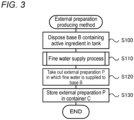
- FIG. 3 is a process chart illustrating an example of an external preparation producing method.
- An operator such as a manufacturer of the external preparation P first disposes the base B containing the above-mentioned active ingredient in the supply tank 50 (step S100).
- the operator operates the start switch 62 to perform the fine water supply process by the fine water supply unit 20 (step S110). Note that it is assumed here that the stirring switch 66 has been turned on and "stirring operation is performed" has thus been set.
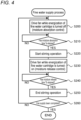
- FIG. 4 is a flowchart illustrating an example of the fine water supply process.
- the control unit 60 performs moisture absorption control in which the fan 40 is driven while energization to the fine water generation cartridge 30 is turned off so that moisture adsorbs to the conductive polymer film 34b (S200), and the controller waits for a predetermined moisture absorption time Ta to elapse (S210).
- the control unit 60 drives the fan 40 to rotate in the second rotation direction. Therefore, the air sucked into the air passage 22 from the opening 21b in the supply tank 50 is released from the opening 21a (see the solid arrows in FIG. 1 ).
- control unit 60 since control unit 60 turns off the energization circuit 35, the energization circuit 35 enters the non-energization state in which energization to the base material 34a is cut off, and the temperature of the conductive polymer film 34b decreases, thereby promoting adsorption of moisture.
- control unit 60 determines in S210 that the moisture absorption time Ta has elapsed, the control unit 60 activates the stirring device 55 to start the stirring operation of the base B (S220), and the control unit 60 drive the fan 40 in the first rotation direction to perform moisture release control while the energization to the fine water generation cartridge 30 is turned on (S230).
- the control unit 60 rotationally drives the fan 40 in the first rotation direction. Therefore, the air sucked into the air passage 22 from the opening 21a outside the supply tank 50 is released into the supply tank 50 from the opening 21b (see the dotted arrows in FIG. 1 ).
- the control unit 60 turns on the energization circuit 35, the energization circuit 35 enters the energization state for energizing the base material 34a, and the temperature of the conductive polymer film 34b increases, thereby promoting the release of the fine water.
- the released fine water is supplied into the supply tank 50 together with air and is radiated on the base B.
- the base B is irradiated with the fine water while being stirred, the fine water can be uniformly supplied to the base B and mixed.
- the control unit 60 After the control unit 60 performs the moisture release control in S230, the control unit 60 waits for a predetermined moisture release time Tb to elapse (S240), and if the control unit 60 determines that the moisture release time Tb has elapsed, the control unit 60 stops the operation of the stirring device 55 to end the stirring operation of the base B (S250) and determines if the supply of fine water has been completed (S260). If the control unit 60 determines that the supply of fine water is not completed, the control unit 60 returns to S200 to perform the moisture absorption control. In this manner, the control unit 60 alternately repeats the moisture absorption control and the moisture release control.
- the moisture absorption time Ta and the moisture release time Tb can be appropriately set in accordance with a moisture absorption capacity (moisture release capacity) of the fine water generation cartridge 30, a size of the supply tank 50, a type and amount of the base B, the active ingredient to be contained, and the like.
- a moisture absorption capacity moisture release capacity
- the moisture absorption time Ta is set to about twice the moisture release time Tb, and when the moisture release time Tb is set to 30 seconds or 1 minute, the moisture absorption time Ta is set to 1 minute, 2 minutes, or the like.
- control unit 60 determines in S260 that the supply of the fine water has been completed, the control unit 60 ends the fine water supply process.
- the worker takes out, from the supply tank 50, the external preparation P produced by the fine water being supplied to the base B (S120) and stores the external preparation P in a predetermined container C for the external preparation P (S130).
- the external preparation producing method is ended.
- the fine water is mainly contained in the base B, but the fine water may be contained in the active ingredient in the base B or may be contained in both the base B and the active ingredient.
- a predetermined amount of the thus produced external preparation P is taken out from the container C by a user and applied to skin or hair.
- the external preparation P may be applied after fine water is supplied to the external preparation P until immediately before use (application).
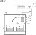
- FIG. 5 is a configuration diagram schematically illustrating a configuration of a fine water permeation chamber 15.
- the fine water permeation chamber 15 includes: a fine water supply unit 20; a supply tank 50B; and a control unit 60, and is disposed at a delivery agent (sales floor) of the external preparation P, an aesthetic salon, and the like.
- the supply tank 50B does not include a stirring device 55, and containers C from which lids are removed are disposed.
- the supply tank 50B is configured to be vertically dividable, for example, and the containers C are put in and taken out in a state where the upper sides (lids) are removed. Of course, it may be taken in and out through an opening 50a in a side wall, like the supply tank 50.
- FIG. 6 is a process chart illustrating an example of an external preparation application method.
- a practitioner store clerk of a delivery agent, an aesthetic salon, or the like places the container C (external preparation P) with the lid opened, in the supply tank 50B (step S300).
- the practitioner operates a start switch 62 of the fine water permeation chamber 15 to perform a fine water supply process by the fine water supply unit 20 (step S310).
- Step S310 is performed similarly to the fine water supply process in FIG. 4 except that there is no stirring operation, and the description thereof is therefore omitted.
- the practitioner takes out the container C in which fine water is supplied (replenished) to the external preparation P (step S320) and applies the external preparation P to the skin or hair of a person being treated to cause the external preparation P to permeate into the skin or hair by a permeation route formed by the fine water and by a permeation force of the fine water (step S330), and the process of external preparation application is ended.
- the fine water permeation chamber 15 may be disposed at the home of a purchaser of the external preparation P and at other places, and the purchaser (user) of the external preparation P may perform the external preparation application method of FIG. 6 .
- FIG. 7 is an explanatory view illustrating an image in which the fine water permeates into skin.
- an epidermis of skin includes a stratum corneum covered with a sebum membrane, a stratum granulosum, a stratum spinosum, a basal layer (not illustrated), and the like.
- the fine water enters the stratum corneum and enters the intercellular lipids between the horny cells (see the arrows in FIG. 7 ).
- the horny surface has gaps of about 20 to 50 nanometers or less. Since the fine water has a particle size of 50 nanometers or less and about 1 to 2 nanometers, the fine water easily enters into the stratum corneum.
- the skin is generally positively charged, if the water particles are negatively charged, the water particles are electrically attracted by the skin surface and hardly enter into the stratum corneum, and if the water particles are positively charged, the water particles are repelled and hardly reach the skin surface. Because the fine water is not charged, such situations do not occur.
- the fine water that has thus entered into the stratum corneum forms routes of water along the intercellular lipids around the horny cells. At that time, the moisture amount of the intercellular lipids is improved, and the moisture also enters into the natural moisturizing component in the horny cells; therefore, the moisture amount of the entire stratum corneum can be brought close to an appropriate value, thereby improving the moisture retaining property.
- the active ingredient of the external preparation P passes through the routes of water formed in the intercellular lipids by the fine water and diffuses in the skin; therefore, permeation of the active ingredient can be promoted.
- the routes of water are formed of fine water and the medicinal agent is diffused through the routes
- the fine water provides the effect of improving the moisture retaining property due to the supply of moisture, and provides synergistically provides the effect of improving the permeability of the active ingredient accompanying the formation of the routes of water formed of fine water or provides the effect of improving the permeability of the active ingredient due to the permeation force of the fine water.
- the fine water similarly permeates into and remains in the fine gaps (about 50 nm or less) between cuticles on the hair surface to moisturize the hair, and water routes are formed of fine water.
- the medical substance diffuses through the water routes, and, in addition, the medicinal agent is pushed in together with the fine water by the permeation force of the fine water.
- the external preparation P described above contains fine water having a particle size of less than or equal to 50 nanometers in the base B (or the active ingredient). Therefore, when the external preparation P is applied to skin or hair, the fine water permeates, so that routes of water in which the active ingredient permeates can be formed and so that moisturization can be sufficiently performed. Therefore, it is possible to enhance the moisturizing effect and the permeation effect.
- the base B may be either fat-soluble or water-soluble, but if the base B is fat-soluble, the base B more easily permeates into skin or the like than the water-soluble base B; therefore, it is possible to further improve the permeability of the active ingredient due the contained fine water.
- the fine water supply device 10 supplies the fine water in the state where the base B is disposed in the supply tank 50, the external preparation P containing the fine water in the base B can be appropriately produced.
- the fine water supply device 10 stirs the base B with the stirring device 55 when the fine water generation cartridge 30 is in the moisture release state, the fine water can be uniformly contained in the base B.
- the external preparation P since the fine water is supplied to the external preparation P disposed in the supply tank 50B of the fine water permeation chamber 15 until immediately before application (use), the external preparation P can be applied in the state of sufficiently containing the fine water. Therefore, for example, even when part of the contained fine water evaporates during a period from when the external preparation P is produced to when the external preparation P is used, the fine water can be replenished before application. Therefore, the moisturizing effect and the permeation effect by the fine water can be appropriately exhibited.
- FIG. 8 is a configuration diagram schematically illustrating a configuration of a fine water supply device 100 of the second embodiment.
- the fine water supply device 100 includes a fine water supply unit 120, a supply tank 150, and a control unit 160.
- the fine water supply unit 120 includes an air passage 121, a fine water generation cartridge 130, an energization circuit 135, and a fan 140, and has the same configuration as the first embodiment except the air passage 121; therefore, the description thereof is omitted.
- the air passage 121 includes a main passage 122, a first communication passage 124, and a second communication passage 127, and is provided with a first switching part 125 and a second switching part 128.
- the main passage 122 is a tubular passage whose both ends are opened.
- the fan 140 and the fine water generation cartridge 130 are provided in this order from a first opening 122a on one side toward a second opening 122b on the other side.
- the first communication passage 124 and the second communication passage 127 communicate the main passage 122 with the supply tank 150.
- the first communication passage 124 is connected to the main passage 122 on the first opening 122a side with respect to the fan 140 and extends into the supply tank 150.
- the second communication passage 127 is connected to the main passage 122 on the second opening 122b side with respect to the fine water generation cartridge 130 and extends into the supply tank 150.
- the first switching part 125 includes a switching plate 126 that operates by being driven by a motor (not illustrated), and the second switching part 128 includes a switching plate 129 that operates by being driven by a motor (not illustrated).
- the first switching part 125 closes (blocks) the first communication passage 124 and opens the first opening 122a side to allow air to flow through the first opening 122a.
- the second switching part 128 closes (blocks) the second communication passage 127 and opens the second opening 122b side to allow air to flow through the second opening 122b.
- the mixing tank 112 is blocked from the main passage 122 and sealed; therefore, this state is referred to as a sealed state (blocked state).
- the first switching part 125 opens the first communication passage 124 and closes the first opening 122a side to block the flow of air through the first opening 122a.
- the second switching part 128 opens the second communication passage 127 and closes the second opening 122b side to block the flow of air through the second opening 122b.
- this state is referred to as a circulation state (communication state).
- the fan 140 rotates in a first rotation direction to blow air from the first opening 122a side toward the second opening 122b side. Furthermore, the fan 140 rotates in a second rotation direction opposite to the first rotation direction to blow air from the second opening 122b side toward the first opening 122a side.
- FIG. 9 is a flowchart illustrating an example of a fine water supply process according to the second embodiment.
- the same processing as that in the first embodiment ( FIG. 4 ) is denoted by the same step number, and a detailed description thereof is omitted.
- the control unit 160 establishes the above-described sealed state and performs moisture absorption control in which the fan 140 is rotationally driven in the second rotation direction while energization to the fine water generation cartridge 130 is turned off, thereby causing moisture to adsorb to the conductive polymer film 34b (S200b). Therefore, the air sucked into the main passage 122 from the second opening 122b flows toward the first opening 122a (see the solid arrows in FIG. 8 ), and the temperature of the conductive polymer film 34b decreases since the energization circuit 35 is turned off, so that the adsorption of moisture is promoted.
- the rotation direction of the fan 140 may be the first rotation direction.
- the control unit 160 establishes the above-described circulation state and performs moisture release control in which the fan 140 is rotationally driven in the first rotation direction while energization to the fine water generation cartridge 130 is turned on so that the fine water released from the conductive polymer film 34b is supplied into the supply tank 150 (S230b). Therefore, the air sent from the fan 140 circulates such that the air sent from the fan 140 flows from the second communication passage 127 into the supply tank 150 through the fine water generation cartridge 130 and then returns to the main passage 122 through the first communication passage 124 (see the dotted arrows in FIG. 8 ).
- the fine water is supplied from the fine water generation cartridge 130 into the mixing tank 112 by using the circulating air without causing new air to flow in, the number of particles of the fine water in the mixing tank 112 increases, so that a high concentration environment of the fine water can be established. This makes it possible to cause the base B to sufficiently absorb the fine water.
- the external preparation application method using the fine water supply device 100 is performed as follows. First, a practitioner disposes the base B as the target agent in the supply tank 150 (step S100). Next, the above-described moisture absorption control (S200b) and the moisture release control (S230b) are repeated, and the fine water is supplied to the base B in a high concentration environment of fine water. Then, after the fine water is supplied to the base B for a predetermined time (S260), the practitioner takes out the target agent from the supply tank 150 and applies, as the external preparation P, the target agent to the skin or hair of a person to be treated.
- the concentration of the fine water in the supply tank 150 can be increased so that the target agent can sufficiently contain the fine water; therefore, it is possible to further improve the moisturizing effect and the permeation effect when the external preparation P is applied to the skin or hair.
- the stirring operation is performed during the moisture release control of the fine water in the fine water supply process, but the present invention is not limited thereto, and the stirring operation may be performed during the moisture absorption control, or the stirring operation may be performed during both the moisture release control and the moisture absorption control.
- the present invention does not need to include the stirring device 55 or 155, and it is not necessary to include the stirring device 55 or 155.
- the external preparation P may be produced by storing the base B in the container C, and the fine water may be supplied by the fine water supply device 10 or 100 in a state where the lid of the container C is opened.
- the fine water in the fine water supply process, the fine water is continuously suppled (constantly supplied) while the moisture absorption control and the moisture release control are alternately performed, but the present invention is not limited thereto.
- an operation time and a non-operation time may be settable so that the fine water may be intermittently supplied by stopping the moisture absorption control and the moisture release control in the non-operation time.
- the fine water supply unit 20 or 120 of each embodiment may include a temperature control cartridge (heat exchanger) in addition to the fine water generation cartridge 30 or 130 and the fan 40 or 140.
- the temperature control cartridge is formed of a metal material in, for example, a corrugated plate shape, a honeycomb shape, a spiral shape, or the like so that the temperature control cartridge has a large heat capacity and high heat exchange efficiency. Then, the air containing the fine water released from the fine water generation cartridge 30 or 130 during the moisture release control may be supplied into the supply tank 50 (50B) or 150 after passing through the temperature control cartridge. In this way, because the air whose temperature has increased in the fine water generation cartridge 30 or 130 is cooled to near room temperature when passing through the temperature control cartridge, the fine water can be appropriately supplied without raising the temperature of the target agent such as the base B.
- a humidity sensor is provided in the supply tank 50 (50B) or 150, and the humidity detected by the humidity sensor is used as an alternative characteristic of the number of fine water particles, thereby adjusting the moisture absorption time Ta, the moisture release time Tb, and a non-operation time between the moisture absorption control and the moisture release control, adjusting the air volume for the moisture release control and the moisture release control, and determining completion of the supply of the fine water.
- the external preparation application method (S330) corresponds to the first cosmetic treatment method.
- the fine water supply device 10 (100) corresponds to the "fine water supply device”
- the fine water generation cartridge 30 (130) corresponds to the "fine water generator”
- the control unit 60 (160) corresponds to the "control unit”.
- the stirring device 55 (155) corresponds to the "stirring unit”.
- the present disclosure can be used for cosmetic treatment in which an external preparation for skin or hair is applied.
Landscapes
- Health & Medical Sciences (AREA)
- Chemical & Material Sciences (AREA)
- Life Sciences & Earth Sciences (AREA)
- Engineering & Computer Science (AREA)
- General Health & Medical Sciences (AREA)
- Public Health (AREA)
- Veterinary Medicine (AREA)
- Animal Behavior & Ethology (AREA)
- Epidemiology (AREA)
- Organic Chemistry (AREA)
- Nanotechnology (AREA)
- Medicinal Chemistry (AREA)
- Pharmacology & Pharmacy (AREA)
- Dispersion Chemistry (AREA)
- Physics & Mathematics (AREA)
- Crystallography & Structural Chemistry (AREA)
- Birds (AREA)
- Chemical Kinetics & Catalysis (AREA)
- Bioinformatics & Cheminformatics (AREA)
- Biomedical Technology (AREA)
- Hematology (AREA)
- Dermatology (AREA)
- Heart & Thoracic Surgery (AREA)
- Anesthesiology (AREA)
- Biophysics (AREA)
- Biotechnology (AREA)
- General Engineering & Computer Science (AREA)
- Medical Informatics (AREA)
- Molecular Biology (AREA)
- Rehabilitation Therapy (AREA)
- Physical Education & Sports Medicine (AREA)
- Pain & Pain Management (AREA)
- Condensed Matter Physics & Semiconductors (AREA)
- General Physics & Mathematics (AREA)
- Manufacturing & Machinery (AREA)
- Geometry (AREA)
- Cosmetics (AREA)
Abstract
Description
- The present disclosure relates to an external preparation for skin or hair, a cosmetic treatment method, and a fine water supply device.
- Conventionally, there have been proposed a product, a method, and a device that promote permeability, to skin, of an external preparation such as a cosmetic liquid applied to the skin. For example, Patent Literature 1 describes a method and a device to increase a permeation amount of an external preparation by generating charged fine particles by using discharge in the atmosphere and releasing the charged fine particles to the external preparation that is applied to skin. Patent Literature 2 describes a method and a device to promote permeation of a cosmetic component into skin by applying the cosmetic component to the skin and then irradiating the skin with positive ions and negative ions that are bonded to water molecules by discharge in the atmosphere.
-
- Patent Literature 1:
JP 2016 -59703 A - Patent Literature 2:
WO 2015/156017 A - However, when an external preparation or water particles are charged by discharge or the like as described above, the external preparation or the water particles are electrically sucked by a surface of a horny layer of the skin, and the permeability into the horny layer may be rather reduced. Furthermore, in the case where ions are further irradiated after the cosmetic component is applied to the skin, it takes time to perform a treatment.
- The present disclosure is to more appropriately improve the permeability of an active ingredient when an external preparation is applied to skin or hair.
- The present disclosure has adopted the following means to achieve the above product, method, and device.
- An external preparation of the present disclosure is an external preparation for skin or hair and includes: a predetermined active ingredient; and a base. At least one of the active ingredient and the base contains fine water that is uncharged and has a particle size of less than or equal to 50 nanometers.
- The external preparation of the present disclosure contains, in at least one of the active ingredient and the base, fine water that is uncharged and has a particle size of less than or equal to 50 nanometers. When the external preparation is applied to skin or hair, the fine water enters the skin or hair to contribute to maintenance of moisturization, and at the same time, forms a route through which the active ingredient permeates, thereby promoting the permeation of the active ingredient; therefore, the permeability of the active ingredient can be more appropriately improved.
- A first cosmetic treatment method of the present disclosure includes: applying, to skin or hair, an external preparation including a predetermined active ingredient and a base, and at least one of the active ingredient and the base contains fine water that is uncharged and has a particle size of less than or equal to 50 nanometers. Therefore, it is possible to more appropriately improve the permeability of the active ingredient when the external preparation is applied to the skin or hair. The cosmetic treatment method may include supplying fine water to the external preparation until the step of applying is started. In this way, the external preparation can be applied in a state where the external preparation is prevented from being dried and sufficiently contains fine water, so that the permeation effect can be reliably improved.
- A second cosmetic treatment method of the present disclosure includes: disposing, in a tank, a base containing a predetermined active ingredient or an external preparation having the base, as a target agent; increasing a concentration of the fine water in the tank, by repeating a moisture absorption state to adsorb moisture in the air to the conductive polymer film in which air outside the tank is supplied to a conductive polymer film at a lowered temperature while an inside of the tank is sealed, and a moisture release state to cause the moisture adsorbed to the conductive polymer film to be released into the tank as fine water having a particle size of less than or equal to 50 nanometers in which the air in the tank is circulated to the conductive polymer film at a raised temperature; supplying the fine water to the target agent for a predetermined time; and taking out the target agent from the tank and applying the target agent to skin or hair as an external preparation.
- In the second cosmetic treatment method of the present disclosure, the fine water is supplied to the target agent for a predetermined time in a state where the concentration of the fine water in the tank is increased, and the target agent is taken out from the tank and applied to skin or hair as an external preparation. Therefore, the target agent is applied after the fine water is made to be sufficiently contained in the target agent, so that the permeability of the active ingredient can be further improved while enhancing a moisturizing effect.
- A fine water supply device of the present disclosure includes: a fine water generator that changes to a moisture absorption state in which moisture in air is made to be adsorbed to a conductive polymer film due to a decrease in temperature and to a moisture release state in which the moisture adsorbed to the conductive polymer film is made to be released into a tank as fine water having a particle size of less than or equal to 50 nanometers due to an increase in temperature; and a control unit that controls the fine water generator such that, in a state where a base containing a predetermined active ingredient or an external preparation having the base is disposed in the tank as a target agent, the fine water is supplied to the target agent.
- In the fine water supply device of the present disclosure, the fine water generator is controlled such that the fine water is supplied to the target agent in a state where the base or the external preparation is disposed in the tank as the target agent, so that the external preparation containing the fine water can be relatively easily produced. When the external preparation is applied to skin or hair, the permeability of the active ingredient can be more appropriately improved.
- The fine water supply device of the present disclosure may include a stirring unit that stirs the target agent in the tank, and the control unit may control the stirring unit such that the stirring unit stirs the target agent in at least one of the moisture absorption state and the moisture release state. This configuration makes it possible to cause the fine water to be uniformly contained in the base; therefore, the permeability of the active ingredient can be further improved while enhancing the moisturizing effect.
- The fine water supply device of the present disclosure may include a switching part that selects any one of a sealed state in which communication between the fine water generator and the tank is blocked and the air outside the tank is supplied to the fine water generator, and a circulation state in which communication is established between the fine water generator and the tank and air inside the tank is supplied to the fine water generator. The control unit may bring, in the sealed state of the switching part, the fine water generator into the moisture absorption state and may bring, in the circulation state of the switching part, the fine water generator into the moisture release state such that the concentration of the fine water in the tank is increased. This configuration makes it possible to bring the inside of the tank in a high concentration environment of fine water and to cause the fine water to be sufficiently contained in the base.
- The first cosmetic treatment method of the present disclosure may include: adsorbing moisture to a conductive polymer film having a nanochannel; increasing a temperature of the conductive polymer film to release the moisture adsorbed to the conductive polymer film; and causing the fine water to be contained in at least one of the active ingredient and the base. This configuration makes it possible to cause fine water having a smaller particle size to be contained, so that the permeability of the active ingredient can be further improved.
-
-
FIG. 1 is a configuration diagram schematically illustrating a configuration of a finewater supply device 10. -
FIG. 2A is a configuration diagram schematically illustrating a configuration of a finewater generation cartridge 30, andFIG. 2B is a configuration diagram schematically illustrating a configuration of a finewater release element 34. -
FIG. 3 is a process chart illustrating an example of an external preparation producing method. -
FIG. 4 is a flowchart illustrating an example of a fine water supply process. -
FIG. 5 is a configuration diagram schematically illustrating a configuration of a finewater permeation chamber 15. -
FIG. 6 is a process chart illustrating an example of an external preparation application method. -
FIG. 7 is an explanatory view illustrating an image in which fine water permeates into skin. -
FIG. 8 is a configuration diagram schematically illustrating a configuration of a finewater supply device 100 of a second embodiment. -
FIG. 9 is a flowchart illustrating an example of a fine water supply process of the second embodiment. - Next, a first embodiment of the present disclosure will be described with reference to the drawings.
FIG. 1 is a configuration diagram schematically illustrating a configuration of a finewater supply device 10 of a first embodiment,FIG. 2A is a configuration diagram schematically illustrating a configuration of a finewater generation cartridge 30, andFIG. 2B is a configuration diagram schematically illustrating a configuration of a finewater release element 34. The finewater supply device 10 includes: a finewater supply unit 20 that supplies fine water; asupply tank 50 that contains a supply target of the fine water; and acontrol unit 60 that controls the entire device. - Here, the supply target of the fine water is an external preparation P to be applied to skin, hair, or the like, or a base B serving as a base component of the external preparation P. Examples of the external preparation P to be applied to skin include cosmetics such as lotions, serums, milky lotions, and creams, and external preparations such as ointments, gels, and creams. Furthermore, examples of the external preparation P to be applied to hair include hair care preparations such as coloring agents, treatment agents, and perming agents. Furthermore, the base B is mixed with a cosmetic component, a medicinal component, or the like as a predetermined active ingredient. Examples of the base B and the active ingredient include, without being limited thereto: moisturizing components, herbal extracts, enzymes such as tyrosinase, superoxide dismutase, and lipase; vitamins and derivatives thereof such as retinol, ascorbic acid, tocopherol, pyridoxal, and riboflavin; organic dyes such as β-carotene and chlorophyll; moisture components such as glycerin, sorbitol, urea, lactic acid, propylene glycol, polyethylene glycol, and copolymers, and glucose derivatives; emollient components such as paraffin, stearyl alcohol, cetyl alcohol, squalene, silicone oil, and stearyl; treatment components; dandruff inhibition components; pilatory and hair growth components; and the like.
- As illustrated in
FIG. 1 , the finewater supply unit 20 includes aduct 21 in which anair passage 22 is formed, the finewater generation cartridge 30, anenergization circuit 35, and afan 40. The finewater supply unit 20 is attached to thesupply tank 50 such that theduct 21 penetrates through a side wall of thesupply tank 50. - The
duct 21 is a tubular member whose both ends are opened, and has an opening 21a opened laterally (horizontally) outside thesupply tank 50 and an opening 21b opened downward (vertically) inside thesupply tank 50. Theduct 21 and theair passage 22 extend linearly in the horizontal direction from the opening 21a to the inside of thesupply tank 50, and then extend so as to curve downward toward the opening 21b. The finewater generation cartridge 30 and thefan 40 are disposed in a straight portion of theair passage 22 in the order of thefan 40 and the finewater generation cartridge 30 from the opening 21a side. - As illustrated in
FIG. 2A , the finewater generation cartridge 30 includes: acase 32 in a cylindrical shape having such an outer diameter that the case can be disposed in theair passage 22; and a finewater generation element 34 provided in thecase 32. As shown inFIG. 2B , the finewater generation element 34 includes abase material 34a and aconductive polymer film 34b formed on the surface of thebase material 34a. - The
base material 34a is formed of a conductive material such as a metal material including a stainless steel-based metal or a copper-based metal, a carbon material, or a conductive ceramic material. In the present embodiment, a metal foil of stainless steel to which aluminum is added is used. The finewater generation element 34 is formed in a corrugated plate shape, a honeycomb shape, a spiral shape, or the like so that air can flow through and a surface area of thebase material 34a (conductive polymer film 34b) is as large as possible. Anenergization circuit 35 including a power supply and a switch is connected to thebase material 34a. When the switch is turned on by thecontrol unit 60, theenergization circuit 35 enters an energization state for energizing thebase material 34a, and when the switch is turned off by thecontrol unit 60, theenergization circuit 35 enters a non-energization state for cutting off energization to thebase material 34a. - The
conductive polymer film 34b is formed of a polymer compound having conductivity such as a thiophene-based conductive polymer. In the present embodiment, theconductive polymer 34b is formed of PEDOT/PSS (poly (3,4-ethylenedioxythiophene)/poly (styrenesulfonic acid)) among thiophene-based conductive polymers. PEDOT/PSS has a structure in which PEDOT is dispersed in PSS having a sulfonic acid group, which is a hydrogen bondable acidic functional group. In addition, nanochannels which are channels having a nanometer size of about 2 nanometers (nm) are formed at boundary portions between PEDOT and PSS. Because a large amount of a sulfonic acid group is present in the nanochannels, moisture present on the surface ofconductive polymer film 34b moves inside along the sulfonic acid group in the nanochannels due to a concentration difference between the surface and the inside when the amount of moisture on the surface is large and the amount of moisture in the inside is small. Consequently, theconductive polymer film 34b adsorbs moisture. In addition, when the amount of moisture on the surface is small and the amount of moisture inside is large in a state where the moisture is adsorbed inside, the moisture moves to the surface along the sulfonic acid group in the nanochannels due to the concentration difference between the surface and the inside. Consequently, moisture is released as fine water from theconductive polymer film 34b. Furthermore, in a state where the temperature of theconductive polymer film 34b has increased, rapid release of moisture (fine water) is promoted as compared with a case where the moisture moves only by the concentration difference, and in a state where the temperature ofconductive polymer film 34b has decreased, rapid adsorption of moisture is promoted as compared with a case where the moisture moves only by the concentration difference. As described above, the fine water generation cartridge 30 (fine water generation element 34) changes to a moisture absorption state where moisture in the air is adsorbed to theconductive polymer film 34b due to a decrease in temperature, and changes to a moisture release state where the adsorbed moisture is released from theconductive polymer film 34b due to an increase in temperature. Note that a thickness of theconductive polymer film 34b can be appropriately determined in accordance with a required adsorption amount (release amount) of the fine water. For example, whenconductive polymer film 34b is formed to have a thickness of, for example, 1 to 30 micrometers, moisture sufficient to release fine water can be adsorbed to theconductive polymer film 34b in about several seconds to several tens of seconds. - In addition, the fine
water generation cartridge 30 releases, from theconductive polymer film 34b of the finewater generation element 34, uncharged fine water having a water particle size of 50 nanometers or less, for example, a particle size of about 1 to 2 nanometers. The reason that the particles have such a particle size is considered as follows. Since the size of the nanochannels is 2 nanometers or less, the increase in the temperature of the conductive polymer film increases the mobility and a pressure of water in the nanochannels, so that the moisture jumps out from the nanochannels. In addition, even when the water particles aggregate after jumping out, the particle size of the aggregation is distributed in the range of 50 nanometers or less. A detailed description about such generation of fine water in the fine water generation cartridge 30 (conductive polymer film 34b) is described inWO 2020/054100 A ,JP 2019-018195 A - The
fan 40 rotates in a first rotation direction to blow air from theopening 21a outside thesupply tank 50 toward theopening 21b inside thesupply tank 50. Therefore, the air sucked into theair passage 22 can be sent into thesupply tank 50 through the finewater generation cartridge 30. In addition, being rotationally driven in a second rotation direction opposite to the first rotation direction, thefan 40 blows air from theopening 21b in thesupply tank 50 toward theopening 21a outside thesupply tank 50. Thefan 40 is rotationally driven by a motor (not illustrated), and is controlled by thecontrol unit 60 by pulse width modulation (PWM) control, voltage control, or the like. Note that thefan 40 may be a propeller fan, a sirocco fan, or the like. - The
supply tank 50 is a case having a rectangular parallelepiped shape or a tubular shape, the finewater supply unit 20 is attached to the side wall as described above, and there are formed, in the side walls, anopening 50a for putting in and taking out the base B as the supply target or the like and anexhaust port 50b for exhausting the air in thesupply tank 50 to the outside. Theopening 50a can be manually opened and closed with an opening and closingplate 51. In addition, thesupply tank 50 is provided with a stirringdevice 55 for stirring the base B and the like as the supply target. - The stirring
device 55 includes: amotor 56 fixed to an upper wall of thesupply tank 50; ashaft 57 connected to a rotation shaft of themotor 56 and extending downward; and a plurality of stirringblades 58 radially extending in the horizontal direction from a lower end of theshaft 57. The stirringdevice 55 transmits a rotational driving force of themotor 56 to thestirring blades 58 via theshaft 57, and rotates thestirring blades 58 to stir the base B and the like. - The
control unit 60 is configured as a microprocessor mainly configured with a CPU, and includes a ROM, a RAM, and input and output ports in addition to the CPU. To thecontrol unit 60 there are input, via the input port: an operation signal from astart switch 62 to start an operation of the fine water supply device 10 (fine water supply unit 20); an operation signal from an airvolume control switch 64 to control an air volume of thefan 40; an operation signal from a stirringswitch 66 to set the presence or absence of the stirring operation by the stirringdevice 55; and other signals. Furthermore, from thecontrol unit 60 there are output, via the output port: a drive signal to the motor for rotationally driving thefan 40; a drive signal to the switch of theenergization circuit 35; a drive signal to themotor 56 of the stirringdevice 55; and other signals. - Next, a description will be given on a method for producing the external preparation P by using the fine
water supply device 10 configured as described above and an application method for applying the produced external preparation P to skin or hair.FIG. 3 is a process chart illustrating an example of an external preparation producing method. An operator such as a manufacturer of the external preparation P first disposes the base B containing the above-mentioned active ingredient in the supply tank 50 (step S100). Next, the operator operates thestart switch 62 to perform the fine water supply process by the fine water supply unit 20 (step S110). Note that it is assumed here that the stirringswitch 66 has been turned on and "stirring operation is performed" has thus been set. -
FIG. 4 is a flowchart illustrating an example of the fine water supply process. In the fine water supply process, thecontrol unit 60 performs moisture absorption control in which thefan 40 is driven while energization to the finewater generation cartridge 30 is turned off so that moisture adsorbs to theconductive polymer film 34b (S200), and the controller waits for a predetermined moisture absorption time Ta to elapse (S210). In the moisture absorption control, thecontrol unit 60 drives thefan 40 to rotate in the second rotation direction. Therefore, the air sucked into theair passage 22 from theopening 21b in thesupply tank 50 is released from theopening 21a (see the solid arrows inFIG. 1 ). In addition, sincecontrol unit 60 turns off theenergization circuit 35, theenergization circuit 35 enters the non-energization state in which energization to thebase material 34a is cut off, and the temperature of theconductive polymer film 34b decreases, thereby promoting adsorption of moisture. - If the
control unit 60 determines in S210 that the moisture absorption time Ta has elapsed, thecontrol unit 60 activates the stirringdevice 55 to start the stirring operation of the base B (S220), and thecontrol unit 60 drive thefan 40 in the first rotation direction to perform moisture release control while the energization to the finewater generation cartridge 30 is turned on (S230). In the moisture release control, thecontrol unit 60 rotationally drives thefan 40 in the first rotation direction. Therefore, the air sucked into theair passage 22 from theopening 21a outside thesupply tank 50 is released into thesupply tank 50 from theopening 21b (see the dotted arrows inFIG. 1 ). Furthermore, since thecontrol unit 60 turns on theenergization circuit 35, theenergization circuit 35 enters the energization state for energizing thebase material 34a, and the temperature of theconductive polymer film 34b increases, thereby promoting the release of the fine water. The released fine water is supplied into thesupply tank 50 together with air and is radiated on the base B. As described above, since the base B is irradiated with the fine water while being stirred, the fine water can be uniformly supplied to the base B and mixed. - After the
control unit 60 performs the moisture release control in S230, thecontrol unit 60 waits for a predetermined moisture release time Tb to elapse (S240), and if thecontrol unit 60 determines that the moisture release time Tb has elapsed, thecontrol unit 60 stops the operation of the stirringdevice 55 to end the stirring operation of the base B (S250) and determines if the supply of fine water has been completed (S260). If thecontrol unit 60 determines that the supply of fine water is not completed, thecontrol unit 60 returns to S200 to perform the moisture absorption control. In this manner, thecontrol unit 60 alternately repeats the moisture absorption control and the moisture release control. The moisture absorption time Ta and the moisture release time Tb can be appropriately set in accordance with a moisture absorption capacity (moisture release capacity) of the finewater generation cartridge 30, a size of thesupply tank 50, a type and amount of the base B, the active ingredient to be contained, and the like. Although not particularly limited, for example, the moisture absorption time Ta is set to about twice the moisture release time Tb, and when the moisture release time Tb is set to 30 seconds or 1 minute, the moisture absorption time Ta is set to 1 minute, 2 minutes, or the like. - Furthermore, in S260, for example, when a process time from the start of the fine water supply process reaches a predetermined time such as several tens of minutes, it may be determined that the supply is completed, or when the number of repetitions of the moisture absorption control and the moisture release control reaches a predetermined number of times, it may be determined that the supply is completed. If the
control unit 60 determines in S260 that the supply of the fine water has been completed, thecontrol unit 60 ends the fine water supply process. - In the external preparation producing method in
FIG. 3 , after the fine water supply process in S110 is performed, the worker takes out, from thesupply tank 50, the external preparation P produced by the fine water being supplied to the base B (S120) and stores the external preparation P in a predetermined container C for the external preparation P (S130). The external preparation producing method is ended. Note that the fine water is mainly contained in the base B, but the fine water may be contained in the active ingredient in the base B or may be contained in both the base B and the active ingredient. A predetermined amount of the thus produced external preparation P is taken out from the container C by a user and applied to skin or hair. Alternatively, the external preparation P may be applied after fine water is supplied to the external preparation P until immediately before use (application). -
FIG. 5 is a configuration diagram schematically illustrating a configuration of a finewater permeation chamber 15. Similarly to the finewater supply device 10, the finewater permeation chamber 15 includes: a finewater supply unit 20; asupply tank 50B; and acontrol unit 60, and is disposed at a delivery agent (sales floor) of the external preparation P, an aesthetic salon, and the like. Thesupply tank 50B does not include a stirringdevice 55, and containers C from which lids are removed are disposed. Note that thesupply tank 50B is configured to be vertically dividable, for example, and the containers C are put in and taken out in a state where the upper sides (lids) are removed. Of course, it may be taken in and out through anopening 50a in a side wall, like thesupply tank 50. -
FIG. 6 is a process chart illustrating an example of an external preparation application method. A practitioner (store clerk) of a delivery agent, an aesthetic salon, or the like places the container C (external preparation P) with the lid opened, in thesupply tank 50B (step S300). Next, the practitioner operates astart switch 62 of the finewater permeation chamber 15 to perform a fine water supply process by the fine water supply unit 20 (step S310). Step S310 is performed similarly to the fine water supply process inFIG. 4 except that there is no stirring operation, and the description thereof is therefore omitted. - Then, when the fine water supply process is performed for a predetermined time such as, ten and several minutes or several tens of minutes, the practitioner takes out the container C in which fine water is supplied (replenished) to the external preparation P (step S320) and applies the external preparation P to the skin or hair of a person being treated to cause the external preparation P to permeate into the skin or hair by a permeation route formed by the fine water and by a permeation force of the fine water (step S330), and the process of external preparation application is ended. Note that the fine
water permeation chamber 15 may be disposed at the home of a purchaser of the external preparation P and at other places, and the purchaser (user) of the external preparation P may perform the external preparation application method ofFIG. 6 . - Here,
FIG. 7 is an explanatory view illustrating an image in which the fine water permeates into skin. As illustrated, an epidermis of skin includes a stratum corneum covered with a sebum membrane, a stratum granulosum, a stratum spinosum, a basal layer (not illustrated), and the like. When the external preparation P is applied to the skin, the fine water enters the stratum corneum and enters the intercellular lipids between the horny cells (see the arrows inFIG. 7 ). The horny surface has gaps of about 20 to 50 nanometers or less. Since the fine water has a particle size of 50 nanometers or less and about 1 to 2 nanometers, the fine water easily enters into the stratum corneum. Furthermore, because the skin is generally positively charged, if the water particles are negatively charged, the water particles are electrically attracted by the skin surface and hardly enter into the stratum corneum, and if the water particles are positively charged, the water particles are repelled and hardly reach the skin surface. Because the fine water is not charged, such situations do not occur. The fine water that has thus entered into the stratum corneum forms routes of water along the intercellular lipids around the horny cells. At that time, the moisture amount of the intercellular lipids is improved, and the moisture also enters into the natural moisturizing component in the horny cells; therefore, the moisture amount of the entire stratum corneum can be brought close to an appropriate value, thereby improving the moisture retaining property. In addition, the active ingredient of the external preparation P passes through the routes of water formed in the intercellular lipids by the fine water and diffuses in the skin; therefore, permeation of the active ingredient can be promoted. Note that, in addition to the above-described pattern in which the routes of water are formed of fine water and the medicinal agent is diffused through the routes, there can be considered a pattern of permeation of medicinal agent, in which pattern the medicinal agent is pushed in together with the fine water by the permeation force of the fine water at the same time as the fine water permeates. As described above, the fine water provides the effect of improving the moisture retaining property due to the supply of moisture, and provides synergistically provides the effect of improving the permeability of the active ingredient accompanying the formation of the routes of water formed of fine water or provides the effect of improving the permeability of the active ingredient due to the permeation force of the fine water. How the fine water permeates into the skin is described above. However, the following pattern of permeation of medicinal agent can also be considered. The fine water similarly permeates into and remains in the fine gaps (about 50 nm or less) between cuticles on the hair surface to moisturize the hair, and water routes are formed of fine water. The medical substance diffuses through the water routes, and, in addition, the medicinal agent is pushed in together with the fine water by the permeation force of the fine water. - The external preparation P described above contains fine water having a particle size of less than or equal to 50 nanometers in the base B (or the active ingredient). Therefore, when the external preparation P is applied to skin or hair, the fine water permeates, so that routes of water in which the active ingredient permeates can be formed and so that moisturization can be sufficiently performed. Therefore, it is possible to enhance the moisturizing effect and the permeation effect. Note that the base B may be either fat-soluble or water-soluble, but if the base B is fat-soluble, the base B more easily permeates into skin or the like than the water-soluble base B; therefore, it is possible to further improve the permeability of the active ingredient due the contained fine water.
- Furthermore, since the fine
water supply device 10 supplies the fine water in the state where the base B is disposed in thesupply tank 50, the external preparation P containing the fine water in the base B can be appropriately produced. In addition, since the finewater supply device 10 stirs the base B with the stirringdevice 55 when the finewater generation cartridge 30 is in the moisture release state, the fine water can be uniformly contained in the base B. - Furthermore, in the external preparation application method, since the fine water is supplied to the external preparation P disposed in the
supply tank 50B of the finewater permeation chamber 15 until immediately before application (use), the external preparation P can be applied in the state of sufficiently containing the fine water. Therefore, for example, even when part of the contained fine water evaporates during a period from when the external preparation P is produced to when the external preparation P is used, the fine water can be replenished before application. Therefore, the moisturizing effect and the permeation effect by the fine water can be appropriately exhibited. - Next, a second embodiment of the present disclosure will be described.
FIG. 8 is a configuration diagram schematically illustrating a configuration of a finewater supply device 100 of the second embodiment. The finewater supply device 100 includes a finewater supply unit 120, asupply tank 150, and acontrol unit 160. The finewater supply unit 120 includes anair passage 121, a finewater generation cartridge 130, anenergization circuit 135, and afan 140, and has the same configuration as the first embodiment except theair passage 121; therefore, the description thereof is omitted. - The
air passage 121 includes amain passage 122, afirst communication passage 124, and asecond communication passage 127, and is provided with afirst switching part 125 and asecond switching part 128. Themain passage 122 is a tubular passage whose both ends are opened. In themain passage 122, thefan 140 and the finewater generation cartridge 130 are provided in this order from afirst opening 122a on one side toward asecond opening 122b on the other side. Thefirst communication passage 124 and thesecond communication passage 127 communicate themain passage 122 with thesupply tank 150. Thefirst communication passage 124 is connected to themain passage 122 on thefirst opening 122a side with respect to thefan 140 and extends into thesupply tank 150. Thesecond communication passage 127 is connected to themain passage 122 on thesecond opening 122b side with respect to the finewater generation cartridge 130 and extends into thesupply tank 150. - The
first switching part 125 includes aswitching plate 126 that operates by being driven by a motor (not illustrated), and thesecond switching part 128 includes aswitching plate 129 that operates by being driven by a motor (not illustrated). As indicated by the solid lines inFIG. 8 , when the switchingplate 126 is at a normal position (initial position), thefirst switching part 125 closes (blocks) thefirst communication passage 124 and opens thefirst opening 122a side to allow air to flow through thefirst opening 122a. Further, when the switchingplate 129 is at a normal position, thesecond switching part 128 closes (blocks) thesecond communication passage 127 and opens thesecond opening 122b side to allow air to flow through thesecond opening 122b. In this state, the mixing tank 112 is blocked from themain passage 122 and sealed; therefore, this state is referred to as a sealed state (blocked state). - On the other hand, as indicated by the dotted lines in
FIG. 8 , when driving of the motor causes theswitching plate 126 to operate and move to an operation position where the switchingplate 126 is rotated by 90 degrees, thefirst switching part 125 opens thefirst communication passage 124 and closes thefirst opening 122a side to block the flow of air through thefirst opening 122a. Furthermore, when driving of the motor causes thesecond switching plate 129 to operate and move to an operation position where the switchingplate 129 is rotated by 90 degrees, thesecond switching part 128 opens thesecond communication passage 127 and closes thesecond opening 122b side to block the flow of air through thesecond opening 122b. In this state, the mixing tank 112 and themain passage 122 communicate with each other through thefirst communication passage 124 and thesecond communication passage 127, so that air can circulate through the mixing tank 112 and themain passage 122; therefore, this state is referred to as a circulation state (communication state). - Note that the
fan 140 rotates in a first rotation direction to blow air from thefirst opening 122a side toward thesecond opening 122b side. Furthermore, thefan 140 rotates in a second rotation direction opposite to the first rotation direction to blow air from thesecond opening 122b side toward thefirst opening 122a side. - An operation of the fine
water supply device 100 configured as described above will be described. Here, the operation in a case of performing the fine water supply process of S 110 of the external preparation producing method inFIG. 3 will be described.FIG. 9 is a flowchart illustrating an example of a fine water supply process according to the second embodiment. In this fine water supply process, the same processing as that in the first embodiment (FIG. 4 ) is denoted by the same step number, and a detailed description thereof is omitted. - In the fine water supply process, the
control unit 160 establishes the above-described sealed state and performs moisture absorption control in which thefan 140 is rotationally driven in the second rotation direction while energization to the finewater generation cartridge 130 is turned off, thereby causing moisture to adsorb to theconductive polymer film 34b (S200b). Therefore, the air sucked into themain passage 122 from thesecond opening 122b flows toward thefirst opening 122a (see the solid arrows inFIG. 8 ), and the temperature of theconductive polymer film 34b decreases since theenergization circuit 35 is turned off, so that the adsorption of moisture is promoted. Note that the rotation direction of thefan 140 may be the first rotation direction. - Furthermore, when a stirring operation of a stirring device 155 has been started in S220, the
control unit 160 establishes the above-described circulation state and performs moisture release control in which thefan 140 is rotationally driven in the first rotation direction while energization to the finewater generation cartridge 130 is turned on so that the fine water released from theconductive polymer film 34b is supplied into the supply tank 150 (S230b). Therefore, the air sent from thefan 140 circulates such that the air sent from thefan 140 flows from thesecond communication passage 127 into thesupply tank 150 through the finewater generation cartridge 130 and then returns to themain passage 122 through the first communication passage 124 (see the dotted arrows inFIG. 8 ). As a result, since the fine water is supplied from the finewater generation cartridge 130 into the mixing tank 112 by using the circulating air without causing new air to flow in, the number of particles of the fine water in the mixing tank 112 increases, so that a high concentration environment of the fine water can be established. This makes it possible to cause the base B to sufficiently absorb the fine water. - The external preparation application method using the fine
water supply device 100 is performed as follows. First, a practitioner disposes the base B as the target agent in the supply tank 150 (step S100). Next, the above-described moisture absorption control (S200b) and the moisture release control (S230b) are repeated, and the fine water is supplied to the base B in a high concentration environment of fine water. Then, after the fine water is supplied to the base B for a predetermined time (S260), the practitioner takes out the target agent from thesupply tank 150 and applies, as the external preparation P, the target agent to the skin or hair of a person to be treated. As described above, in the external preparation application method (second cosmetic treatment method) of the second embodiment, the concentration of the fine water in thesupply tank 150 can be increased so that the target agent can sufficiently contain the fine water; therefore, it is possible to further improve the moisturizing effect and the permeation effect when the external preparation P is applied to the skin or hair. - In each of the above-described embodiments, the stirring operation is performed during the moisture release control of the fine water in the fine water supply process, but the present invention is not limited thereto, and the stirring operation may be performed during the moisture absorption control, or the stirring operation may be performed during both the moisture release control and the moisture absorption control. Alternatively, the present invention does not need to include the stirring
device 55 or 155, and it is not necessary to include the stirringdevice 55 or 155. Furthermore, in the process of producing the external preparation P, the external preparation P may be produced by storing the base B in the container C, and the fine water may be supplied by the finewater supply device - In each embodiment, in the fine water supply process, the fine water is continuously suppled (constantly supplied) while the moisture absorption control and the moisture release control are alternately performed, but the present invention is not limited thereto. For example, an operation time and a non-operation time may be settable so that the fine water may be intermittently supplied by stopping the moisture absorption control and the moisture release control in the non-operation time.
- The fine
water supply unit water generation cartridge fan water generation cartridge water generation cartridge - Each embodiment may have the following configuration. A humidity sensor is provided in the supply tank 50 (50B) or 150, and the humidity detected by the humidity sensor is used as an alternative characteristic of the number of fine water particles, thereby adjusting the moisture absorption time Ta, the moisture release time Tb, and a non-operation time between the moisture absorption control and the moisture release control, adjusting the air volume for the moisture release control and the moisture release control, and determining completion of the supply of the fine water.
- The correspondence relationship between the main elements of the embodiments and the main elements of the present disclosure described in the section of SOLUTIONS TO PROBLEMS will be described. In the embodiments, the external preparation application method (S330) corresponds to the first cosmetic treatment method. Furthermore, the fine water supply device 10 (100) corresponds to the "fine water supply device", the fine water generation cartridge 30 (130) corresponds to the "fine water generator ", and the control unit 60 (160) corresponds to the "control unit". The stirring device 55 (155) corresponds to the "stirring unit".
- Note that the correspondence relationship between the main elements of the embodiments and the main elements of the present disclosure described in the section of SOLUTIONS TO PROBLEMS is an example for specifically describing forms for carrying out the present disclosure described in the section of SOLUTIONS TO PROBLEMS; therefore, the correspondence relationship does not limit the elements of the present disclosure described in the section of SOLUTIONS TO PROBLEMS. That is, the interpretation of the present disclosure described in the section of SOLUTIONS TO PROBLEMS should be made based on the description in the section, and the embodiments are merely a specific example of the present disclosure described in the section of SOLUTIONS TO PROBLEMS Although the embodiments for carrying out the present disclosure have been described above with reference to the embodiments, the present disclosure is not limited to such embodiments at all, and can be carried out in various forms without departing from the gist of the present disclosure.
- The present disclosure can be used for cosmetic treatment in which an external preparation for skin or hair is applied.
Claims (7)
- An external preparation for skin or hair comprising:a predetermined active ingredient; and a base,wherein at least one of the active ingredient and the base contains fine water that is uncharged and has a particle size of less than or equal to 50 nanometers.
- A cosmetic treatment method comprising
applying, to skin or hair, an external preparation including a predetermined active ingredient and a base, wherein at least one of the active ingredient and the base contains fine water that is uncharged and has a particle size of less than or equal to 50 nanometers. - A cosmetic treatment method comprising:disposing, in a tank, a base containing a predetermined active ingredient or an external preparation having the base, as a target agent;increasing a concentration of the fine water in the tank, by repeating a moisture absorption state to adsorb moisture in the air to the conductive polymer film in which air outside the tank is supplied to a conductive polymer film at a lowered temperature while an inside of the tank is sealed, and a moisture release state to cause the moisture adsorbed to the conductive polymer film to be released into the tank as fine water having a particle size of less than or equal to 50 nanometers in which the air in the tank is circulated to the conductive polymer film at a raised temperature;supplying the fine water to the target agent for a predetermined time; andtaking out the target agent from the tank and applying the target agent to skin or hair as an external preparation.
- A fine water supply device comprising:a fine water generator that changes to a moisture absorption state in which moisture in air is made to be adsorbed to a conductive polymer film due to a decrease in temperature and to a moisture release state in which the moisture adsorbed to the conductive polymer film is made to be released into a tank as fine water having a particle size of less than or equal to 50 nanometers due to an increase in temperature; anda control unit that controls the fine water generator such that, in a state where a base containing a predetermined active ingredient or an external preparation having the base is disposed in the tank as a target agent, the fine water is supplied to the target agent.
- The fine water supply device according to claim 4, further comprising a stirring unit that stirs the target agent in the tank,
wherein the control unit controls the stirring unit such that the stirring unit stirs the target agent in at least one of the moisture absorption state and the moisture release state. - The fine water supply device according to claim 5, further comprising a switching part that selects any one of a sealed state in which communication between the fine water generator and the tank is blocked and the air outside the tank is supplied to the fine water generator, and a circulation state in which communication is established between the fine water generator and the tank and air inside the tank is supplied to the fine water generator,
wherein the control unit brings, in the sealed state of the switching part, the fine water generator unit into the moisture absorption state and brings, in the circulation state of the switching part, the fine water generator into the moisture release state such that a concentration of the fine water in the tank is increased. - The cosmetic treatment method according to claim 2, further comprising:adsorbing moisture to a conductive polymer film having a nanochannel;increasing a temperature of the conductive polymer film to release the moisture adsorbed to the conductive polymer film; andcausing the fine water to be contained in at least one of the active ingredient and the base.
Applications Claiming Priority (4)
| Application Number | Priority Date | Filing Date | Title |
|---|---|---|---|
| JP2021152889A JP7622599B2 (en) | 2021-09-21 | 2021-09-21 | Spray for skin or hair, cosmetic treatment method and spray device |
| JP2021152888A JP7567731B2 (en) | 2021-09-21 | 2021-09-21 | External preparation for skin or hair, cosmetic treatment method, and fine water supply device |
| JP2021165726 | 2021-10-07 | ||
| PCT/JP2022/034955 WO2023048130A1 (en) | 2021-09-21 | 2022-09-20 | Topical agent for skin and hair, cosmetic operation method, and fine water particle supply device |
Publications (2)
| Publication Number | Publication Date |
|---|---|
| EP4406527A1 true EP4406527A1 (en) | 2024-07-31 |
| EP4406527A4 EP4406527A4 (en) | 2025-01-29 |
Family
ID=85776359
Family Applications (2)
| Application Number | Title | Priority Date | Filing Date |
|---|---|---|---|
| EP22872882.0A Pending EP4406527A4 (en) | 2021-09-21 | 2022-09-20 | Topical agent for skin and hair, cosmetic operation method, and fine water particle supply device |
| EP22872940.6A Pending EP4406528A4 (en) | 2021-09-21 | 2022-09-21 | Aerosolized agent for skin or hair, cosmetic treatment method, and spraying device |
Family Applications After (1)
| Application Number | Title | Priority Date | Filing Date |
|---|---|---|---|
| EP22872940.6A Pending EP4406528A4 (en) | 2021-09-21 | 2022-09-21 | Aerosolized agent for skin or hair, cosmetic treatment method, and spraying device |
Country Status (3)
| Country | Link |
|---|---|
| EP (2) | EP4406527A4 (en) |
| JP (1) | JP7567731B2 (en) |
| WO (1) | WO2023048130A1 (en) |
Family Cites Families (8)
| Publication number | Priority date | Publication date | Assignee | Title |
|---|---|---|---|---|
| JP5212654B2 (en) * | 2009-06-30 | 2013-06-19 | 花王株式会社 | Steam generator |
| WO2015156017A1 (en) | 2014-04-10 | 2015-10-15 | シャープ株式会社 | Method for promoting penetration of beauty care ingredient into skin, and device for promoting penetration of beauty care ingredient into skin |
| JP2016059703A (en) | 2014-09-19 | 2016-04-25 | パナソニックIpマネジメント株式会社 | Agent permeability improvement method and device |
| JP7091692B2 (en) * | 2017-07-19 | 2022-06-28 | 株式会社アイシン | Manufacturing method of fine water particle discharging element, fine water particle discharging device and fine water particle discharging element |
| US10987288B2 (en) | 2017-12-08 | 2021-04-27 | Yin-Ming Lo | Deep-sea water concentrate skin application kit and use thereof |
| JP7196923B2 (en) * | 2018-09-14 | 2022-12-27 | 株式会社アイシン | Fine water discharge device |
| JP2020116032A (en) | 2019-01-22 | 2020-08-06 | アイシン精機株式会社 | Heating blower |
| KR102313171B1 (en) * | 2019-11-22 | 2021-10-15 | 안양대학교 산학협력단 | Cosmetics containing ultra-microporous foam for improving skin permeability, cosmetic production system containing ultra-micro-foam foam for improving skin permeability, cosmetic manufacturing method containing ultra-micro-foam foam for improving skin permeability |
-
2021
- 2021-09-21 JP JP2021152888A patent/JP7567731B2/en active Active
-
2022
- 2022-09-20 EP EP22872882.0A patent/EP4406527A4/en active Pending
- 2022-09-20 WO PCT/JP2022/034955 patent/WO2023048130A1/en not_active Ceased
- 2022-09-21 EP EP22872940.6A patent/EP4406528A4/en active Pending
Also Published As
| Publication number | Publication date |
|---|---|
| EP4406527A4 (en) | 2025-01-29 |
| EP4406528A1 (en) | 2024-07-31 |
| JP2023044821A (en) | 2023-04-03 |
| WO2023048130A1 (en) | 2023-03-30 |
| JP7567731B2 (en) | 2024-10-16 |
| EP4406528A4 (en) | 2025-03-12 |
Similar Documents
| Publication | Publication Date | Title |
|---|---|---|
| Richard et al. | Vesicular systems for dermal and transdermal drug delivery | |
| CN101128136B (en) | Device for conveying mechanical energy to large skin | |
| US11464955B2 (en) | Three-dimensional microfluidics devices for the delivery of actives | |
| Bala et al. | Transdermal drug delivery system (TDDS)-a multifaceted approach for drug delivery | |
| EP1194092B1 (en) | Exothermic topical delivery device | |
| CA2727726C (en) | Transdermal delivery apparatus and method | |
| US20150045723A1 (en) | Compositions, methods and apparatus for use with energy activatible materials | |
| JPH08502424A (en) | Ultrasonic transdermal drug delivery system | |
| CA2375655A1 (en) | Exothermic bandage | |
| Martins et al. | Bifunctional therapeutic application of low-frequency ultrasound associated with zinc phthalocyanine-loaded micelles | |
| US20250325757A1 (en) | External preparation for skin or hair, cosmetic treatment method, and fine water supply device | |
| KR20220077962A (en) | Skin care massage device coated with skin improvement substance | |
| JP7567731B2 (en) | External preparation for skin or hair, cosmetic treatment method, and fine water supply device | |
| JP6279255B2 (en) | Coating composition and coated product using the coating composition | |
| CN118019516A (en) | External preparation for skin or hair, beauty application method and micro water supply device | |
| JP7622599B2 (en) | Spray for skin or hair, cosmetic treatment method and spray device | |
| CA3158361A1 (en) | Continuous or periodical transdermal delivery of exogenous molecule | |
| JPWO2023048097A5 (en) | ||
| CN122031290A (en) | Percutaneous permeation promoting system and preparation method and application thereof | |
| KISHORE | TRANSDERMAL DRUG DELIVERY SYSTEMS | |
| JP2023044821A5 (en) | ||
| Prisada et al. | Modalities to enhance the transepidermal penetration of therapeutics of topic usage | |
| Fernandes | Preparation of particles for cosmetic applications in human hair |
Legal Events
| Date | Code | Title | Description |
|---|---|---|---|
| STAA | Information on the status of an ep patent application or granted ep patent |
Free format text: STATUS: THE INTERNATIONAL PUBLICATION HAS BEEN MADE |
|
| PUAI | Public reference made under article 153(3) epc to a published international application that has entered the european phase |
Free format text: ORIGINAL CODE: 0009012 |
|
| STAA | Information on the status of an ep patent application or granted ep patent |
Free format text: STATUS: REQUEST FOR EXAMINATION WAS MADE |
|
| 17P | Request for examination filed |
Effective date: 20240313 |
|
| AK | Designated contracting states |
Kind code of ref document: A1 Designated state(s): AL AT BE BG CH CY CZ DE DK EE ES FI FR GB GR HR HU IE IS IT LI LT LU LV MC MK MT NL NO PL PT RO RS SE SI SK SM TR |
|
| DAV | Request for validation of the european patent (deleted) | ||
| DAX | Request for extension of the european patent (deleted) | ||
| A4 | Supplementary search report drawn up and despatched |
Effective date: 20250107 |
|
| RIC1 | Information provided on ipc code assigned before grant |
Ipc: A61H 33/12 20060101ALI20241220BHEP Ipc: A45D 44/00 20060101ALI20241220BHEP Ipc: A61M 11/00 20060101ALI20241220BHEP Ipc: A61Q 19/00 20060101ALI20241220BHEP Ipc: A61Q 5/00 20060101ALI20241220BHEP Ipc: A61K 8/19 20060101AFI20241220BHEP |