EP4406492A2 - Suture based closure device - Google Patents
Suture based closure device Download PDFInfo
- Publication number
- EP4406492A2 EP4406492A2 EP24176148.5A EP24176148A EP4406492A2 EP 4406492 A2 EP4406492 A2 EP 4406492A2 EP 24176148 A EP24176148 A EP 24176148A EP 4406492 A2 EP4406492 A2 EP 4406492A2
- Authority
- EP
- European Patent Office
- Prior art keywords
- needle
- distal
- suture
- proximal
- shuttle
- Prior art date
- Legal status (The legal status is an assumption and is not a legal conclusion. Google has not performed a legal analysis and makes no representation as to the accuracy of the status listed.)
- Pending
Links
Images


















Classifications
-
- A—HUMAN NECESSITIES
- A61—MEDICAL OR VETERINARY SCIENCE; HYGIENE
- A61B—DIAGNOSIS; SURGERY; IDENTIFICATION
- A61B17/00—Surgical instruments, devices or methods
- A61B17/04—Surgical instruments, devices or methods for suturing wounds; Holders or packages for needles or suture materials
- A61B17/0469—Suturing instruments for use in minimally invasive surgery, e.g. endoscopic surgery
-
- A—HUMAN NECESSITIES
- A61—MEDICAL OR VETERINARY SCIENCE; HYGIENE
- A61B—DIAGNOSIS; SURGERY; IDENTIFICATION
- A61B1/00—Instruments for performing medical examinations of the interior of cavities or tubes of the body by visual or photographical inspection, e.g. endoscopes; Illuminating arrangements therefor
-
- A—HUMAN NECESSITIES
- A61—MEDICAL OR VETERINARY SCIENCE; HYGIENE
- A61B—DIAGNOSIS; SURGERY; IDENTIFICATION
- A61B1/00—Instruments for performing medical examinations of the interior of cavities or tubes of the body by visual or photographical inspection, e.g. endoscopes; Illuminating arrangements therefor
- A61B1/00064—Constructional details of the endoscope body
- A61B1/00071—Insertion part of the endoscope body
- A61B1/0008—Insertion part of the endoscope body characterised by distal tip features
- A61B1/00087—Tools
-
- A—HUMAN NECESSITIES
- A61—MEDICAL OR VETERINARY SCIENCE; HYGIENE
- A61B—DIAGNOSIS; SURGERY; IDENTIFICATION
- A61B1/00—Instruments for performing medical examinations of the interior of cavities or tubes of the body by visual or photographical inspection, e.g. endoscopes; Illuminating arrangements therefor
- A61B1/00131—Accessories for endoscopes
- A61B1/00137—End pieces at either end of the endoscope, e.g. caps, seals or forceps plugs
-
- A—HUMAN NECESSITIES
- A61—MEDICAL OR VETERINARY SCIENCE; HYGIENE
- A61B—DIAGNOSIS; SURGERY; IDENTIFICATION
- A61B1/00—Instruments for performing medical examinations of the interior of cavities or tubes of the body by visual or photographical inspection, e.g. endoscopes; Illuminating arrangements therefor
- A61B1/012—Instruments for performing medical examinations of the interior of cavities or tubes of the body by visual or photographical inspection, e.g. endoscopes; Illuminating arrangements therefor characterised by internal passages or accessories therefor
- A61B1/018—Instruments for performing medical examinations of the interior of cavities or tubes of the body by visual or photographical inspection, e.g. endoscopes; Illuminating arrangements therefor characterised by internal passages or accessories therefor for receiving instruments
-
- A—HUMAN NECESSITIES
- A61—MEDICAL OR VETERINARY SCIENCE; HYGIENE
- A61B—DIAGNOSIS; SURGERY; IDENTIFICATION
- A61B17/00—Surgical instruments, devices or methods
- A61B17/00234—Surgical instruments, devices or methods for minimally invasive surgery
-
- A—HUMAN NECESSITIES
- A61—MEDICAL OR VETERINARY SCIENCE; HYGIENE
- A61B—DIAGNOSIS; SURGERY; IDENTIFICATION
- A61B17/00—Surgical instruments, devices or methods
- A61B17/04—Surgical instruments, devices or methods for suturing wounds; Holders or packages for needles or suture materials
- A61B17/0482—Needle or suture guides
-
- A—HUMAN NECESSITIES
- A61—MEDICAL OR VETERINARY SCIENCE; HYGIENE
- A61B—DIAGNOSIS; SURGERY; IDENTIFICATION
- A61B17/00—Surgical instruments, devices or methods
- A61B17/04—Surgical instruments, devices or methods for suturing wounds; Holders or packages for needles or suture materials
- A61B17/0491—Sewing machines for surgery
-
- A—HUMAN NECESSITIES
- A61—MEDICAL OR VETERINARY SCIENCE; HYGIENE
- A61B—DIAGNOSIS; SURGERY; IDENTIFICATION
- A61B17/00—Surgical instruments, devices or methods
- A61B17/04—Surgical instruments, devices or methods for suturing wounds; Holders or packages for needles or suture materials
- A61B17/06—Needles ; Sutures; Needle-suture combinations; Holders or packages for needles or suture materials
- A61B17/06166—Sutures
-
- A—HUMAN NECESSITIES
- A61—MEDICAL OR VETERINARY SCIENCE; HYGIENE
- A61B—DIAGNOSIS; SURGERY; IDENTIFICATION
- A61B17/00—Surgical instruments, devices or methods
- A61B17/04—Surgical instruments, devices or methods for suturing wounds; Holders or packages for needles or suture materials
- A61B17/06—Needles ; Sutures; Needle-suture combinations; Holders or packages for needles or suture materials
- A61B17/062—Needle manipulators
- A61B17/0625—Needle manipulators the needle being specially adapted to interact with the manipulator, e.g. being ridged to snap fit in a hole of the manipulator
-
- A—HUMAN NECESSITIES
- A61—MEDICAL OR VETERINARY SCIENCE; HYGIENE
- A61B—DIAGNOSIS; SURGERY; IDENTIFICATION
- A61B17/00—Surgical instruments, devices or methods
- A61B17/00234—Surgical instruments, devices or methods for minimally invasive surgery
- A61B2017/00292—Surgical instruments, devices or methods for minimally invasive surgery mounted on or guided by flexible, e.g. catheter-like, means
- A61B2017/00296—Surgical instruments, devices or methods for minimally invasive surgery mounted on or guided by flexible, e.g. catheter-like, means mounted on an endoscope
-
- A—HUMAN NECESSITIES
- A61—MEDICAL OR VETERINARY SCIENCE; HYGIENE
- A61B—DIAGNOSIS; SURGERY; IDENTIFICATION
- A61B17/00—Surgical instruments, devices or methods
- A61B17/00234—Surgical instruments, devices or methods for minimally invasive surgery
- A61B2017/00349—Needle-like instruments having hook or barb-like gripping means, e.g. for grasping suture or tissue
-
- A—HUMAN NECESSITIES
- A61—MEDICAL OR VETERINARY SCIENCE; HYGIENE
- A61B—DIAGNOSIS; SURGERY; IDENTIFICATION
- A61B17/00—Surgical instruments, devices or methods
- A61B2017/00477—Coupling
-
- A—HUMAN NECESSITIES
- A61—MEDICAL OR VETERINARY SCIENCE; HYGIENE
- A61B—DIAGNOSIS; SURGERY; IDENTIFICATION
- A61B17/00—Surgical instruments, devices or methods
- A61B17/0057—Implements for plugging an opening in the wall of a hollow or tubular organ, e.g. for sealing a vessel puncture or closing a cardiac septal defect
- A61B2017/00646—Type of implements
- A61B2017/00663—Type of implements the implement being a suture
-
- A—HUMAN NECESSITIES
- A61—MEDICAL OR VETERINARY SCIENCE; HYGIENE
- A61B—DIAGNOSIS; SURGERY; IDENTIFICATION
- A61B17/00—Surgical instruments, devices or methods
- A61B17/04—Surgical instruments, devices or methods for suturing wounds; Holders or packages for needles or suture materials
- A61B2017/0496—Surgical instruments, devices or methods for suturing wounds; Holders or packages for needles or suture materials for tensioning sutures
-
- A—HUMAN NECESSITIES
- A61—MEDICAL OR VETERINARY SCIENCE; HYGIENE
- A61B—DIAGNOSIS; SURGERY; IDENTIFICATION
- A61B17/00—Surgical instruments, devices or methods
- A61B17/04—Surgical instruments, devices or methods for suturing wounds; Holders or packages for needles or suture materials
- A61B17/06—Needles ; Sutures; Needle-suture combinations; Holders or packages for needles or suture materials
- A61B17/06004—Means for attaching suture to needle
- A61B2017/06047—Means for attaching suture to needle located at the middle of the needle
-
- A—HUMAN NECESSITIES
- A61—MEDICAL OR VETERINARY SCIENCE; HYGIENE
- A61B—DIAGNOSIS; SURGERY; IDENTIFICATION
- A61B17/00—Surgical instruments, devices or methods
- A61B17/04—Surgical instruments, devices or methods for suturing wounds; Holders or packages for needles or suture materials
- A61B17/06—Needles ; Sutures; Needle-suture combinations; Holders or packages for needles or suture materials
- A61B17/06066—Needles, e.g. needle tip configurations
- A61B2017/0609—Needles, e.g. needle tip configurations having sharp tips at both ends, e.g. shuttle needle alternately retained and released by first and second facing jaws of a suturing instrument
Definitions
- the disclosure is directed to devices for suturing tissue and more particularly to devices that work with an endoscope or similar device for endoscopically suturing tissue.
- endoscopic treatments may result in defects (or wounds) that are too large for hemostasis clips to easily bridge and thus help to close the defect.
- endoscopic treatments include removal of large lesions, tunneling under the mucosal layer, full thickness removal of tissue, treating other organs by passing outside of the gastrointestinal tract, and repair of post-surgical issues such as post-surgical leaks, failing surgical staple lines and anastomotic leaks.
- Endoscopic treatments also include bariatric revision procedures. Of the known devices and methods for endoscopically closing large defects, each has certain advantages and disadvantages.
- a suture device for use in combination with a delivery system including a lumen extending through the delivery system includes a suture translation assembly that is configured to be axially translatable within the lumen of the delivery system and a distal assembly that is configured to be securable to the distal end of the delivery system.
- the suture translation assembly may be considered to be an active suture translation assembly while the distal assembly may be considered to be a passive distal assembly.
- the suture translation assembly may move relative to the delivery system while the distal assembly remains stationary relative to the delivery system.
- the suture translation assembly includes a needle usable to carry a suture, a distal shuttle that is configured to releasably secure the needle.
- a user interface extends proximally from the distal shuttle and is configured to releasably secure the needle.
- the distal assembly includes an endcap that is configured to releasably engage and disengage the needle, the endcap configured to engage the needle when the needle is advanced distally into the endcap, and to release the needle when the needle is locked to the distal shuttle and the distal shuttle is withdrawn proximally.
- a guide member is configured to permit the suture translation assembly to extend through the guide member and to translate relative to the guide member.
- the needle may include a distal region and a proximal region, the distal region including a distal detent for releasably engaging the endcap, the proximal region including a proximal detent for releasably engaging the distal shuttle.
- the endcap may include a proximal needle opening that is configured to accommodate the needle when the needle is advanced distally into the endcap, the proximal needle opening aligned with a longitudinal axis of the needle, one or more securement openings that are arranged orthogonal to the proximal needle opening and one or more securements that are disposed within the securement openings and are configured to releasably engage the distal detent of the needle.
- the one or more securement openings may comprise an aperture that tapers from a first diameter that is larger than a diameter of a securement disposed therein to a second diameter that is about equal in diameter to the diameter of the securement.
- the distal assembly further includes a set screw opening that is orthogonal to the securement opening and a set screw threadedly engaged in the set screw opening such that the set screw adjustably engages the securement.
- the set screw opening is disposed closer to the first diameter than to the second diameter.
- the one or more securements may be spring-loaded.
- the guide member may include a channel cut longitudinally into the guide member in order to accommodate a suture therethrough.
- the distal shuttle may include a distal needle opening that is configured to accommodate the needle when the distal shuttle is advanced distally over the needle, the distal needle opening aligned with a longitudinal axis of the needle, one or more bearing ball openings that are arranged orthogonal to the distal needle opening such that the one or more bearing ball openings align with the proximal detent when the needle is secured to the distal shuttle and one or more bearing balls that are disposed within the one or more bearing ball openings and disposable within the proximal detent when the needle is secured to the distal shuttle.
- the user interface may further include a member that is disposable over the distal shuttle and is movable between a locked position in which the needle is secured to the distal shuttle and an unlocked position in which the needle is releasable from the distal shuttle.
- the member may include one or more member openings smaller in diameter than the one or more bearing balls.
- the one or more member openings When in the locked position, the one or more member openings may be misaligned with the one or more bearing ball openings such that the one or more bearing balls engage the proximal detent of the needle and when in the unlocked position, the one or more member openings may be aligned with the one or more bearing ball openings such that the one or more bearing balls can move radially outward a distance sufficient to permit the one or more bearing balls to clear the proximal detent of the needle.
- the user interface may include a proximal handle, a translating handle disposed relative to the proximal handle and a cable extending distally from the translating handle to the member. Axial movement of the translating handle relative to the proximal handle may cause the member to translate relative to the distal shuttle.
- the distal shuttle may further include an internal void and a member capture element slidingly disposed within the internal void, the cable secured to the member capture element and the member capture element secured to the member, such that axial movement of the translating handle relative to the proximal handle causes the member capture element to translate within the internal void and thus permit the member to translate relative to the distal shuttle.
- the member may further include one or more member capture apertures disposed within the sleeve, and the member capture member may be secured to the member via a pin extending through the member capture apertures and through the member capture member.
- the translating handle may have a neutral position.
- moving the translating handle distally from the neutral position may cause the member to move to the locked position and moving the translating handle proximally from the neutral position may cause the member to move to the unlocked position.
- the delivery system may include an endoscope and the lumen may be a working channel of the endoscope.
- the distal shuttle may include an inner member that is configured to accommodate the needle and a locking member that is slidingly disposed over the inner member, the locking member movable between a locked configuration in which the needle is secured to the distal shuttle and an unlocked configuration in which the needle is released from the distal shuttle.
- the inner member may include a plurality of arms that releasably engage a proximal detent in the needle.
- the locking member when in the locked configuration, the locking member is in a position in which the locking member prevents radially outward movement of the plurality of arms, and when in the unlocked configuration, the locking member has been withdrawn proximally relative to the inner member such that the arms are able to move radially outwardly.
- the locking member is coupled to a control member that extends proximally and allows the locking member to be translated distally and proximally relative to the inner member.
- the distal shuttle may include an inner member that is configured to accommodate the needle and a locking member that is slidingly disposed over the inner member, the inner member including one or more slots, the locking member including one or more tabs that releasably extend through the slots in order to engage the proximal detent of the needle.
- the distal shuttle is movable between a locked configuration in which the one or more tabs of the locking member extend through the one or more slots of the inner member and an unlocked configuration in which the tabs are forced distally of the one or more slots, thereby releasing the needle.
- the inner member further includes a pin extending radially outwardly from the inner member
- the locking member further includes an elongate slot to accommodate the pin, the pin and the elongate slot in combination limiting relative translation between the inner member and the locking member.
- a suture device for use in combination with an endoscope having a working channel and a distal end includes a translation assembly configured to be axially translatable within the working channel and a distal assembly configured to be securable to the distal end of the endoscope.
- the translation assembly includes a needle that is configured to carry a suture, a distal shuttle that is configured to releasably secure the needle and a sleeve that is disposable over the distal shuttle and is movable between a locked position in which the needle is secured to the distal shuttle and an unlocked position in which the needle is releasable from the distal shuttle.
- the distal assembly includes an endcap that is configured to engage the needle when the needle is advanced distally into the endcap and to release the needle when the needle is locked to the distal shuttle and the distal shuttle is withdrawn proximally.
- the translation assembly may further include a user interface that extends proximally from the distal shuttle and sleeve and is configured to enable a user to move the sleeve between the locked position and the unlocked position.
- the user interface may include a proximal handle and a translating handle that is disposed relative to the proximal handle and movable both distally and proximally from a neutral position and a cable extending distally from the translating handle to the sleeve.
- Axial movement of the translating handle relative to the proximal handle may cause the sleeve to translate relative to the distal shuttle.
- moving the translating handle distally from the neutral position may cause the sleeve to move to the locked position and moving the translating handle proximally from the neutral position may cause the sleeve to move to the unlocked position.
- translating the proximal handle distally may advance the distal shuttle and thus the needle towards the endcap and translating the proximal handle distally may withdraw the distal shuttle and thus the needle proximally away from the endcap.
- the suture device may further include a flexible silicone tube that is configured to secure the distal assembly to the distal end of the endoscope.
- the distal assembly may further comprise a side-saddled lumen attachment element that is configured to provide a side lumen extending through an aperture in the body of the distal assembly.
- the side-saddled lumen attachment element may be pivotally attached to the aperture in the body of the distal assembly.
- the distal assembly may further comprise a tissue release mechanism that may be pivotally secured relative to the distal assembly.
- the distal assembly may be spring-loaded or actuated via a separate control wire.
- the user interface may include a friction disk that is disposed between the proximal handle and the translating handle such that the friction disk resists relative movement between the proximal handle and the translating handle.
- the translatable needle assembly includes a distal shuttle configured to releasably secure the needle and a sleeve that is disposable over the distal shuttle and is movable between a locked position in which the needle is secured to the distal shuttle and an unlocked position in which the needle is releasable from the distal shuttle.
- a cable is coupled with the distal shuttle and the sleeve and coaxially aligned with the distal shuttle and the sleeve.
- the suture device includes a proximal handle and a translating handle that is disposed relative to the proximal handle and secured to the cable and that is translatable to cause the sleeve to move between the locked position and the unlocked position.
- translating the proximal handle distally may advance the distal shuttle and thus the needle towards the distal assembly and translating the proximal handle distally may withdraw the distal shuttle and thus the needle proximally away from the distal assembly.
- the disclosure pertains to devices that are configured to be used in combination with an endoscope or a similar delivery device for closing wounds within the body.
- the suture devices described herein may be configured such that they may be used within a single working or available channel of an endoscope, and in some cases may be operated by a single individual, although in some cases a second individual may be involved. In some cases, the suture devices described herein may be considered as operating along a single line of operation.
- the device itself may be translatable distally and proximally within a working channel, and a handle portion may itself be translatable distally and proximally along the same line of operation in locking and unlocking a needle to be able to pass the needle back and forth between an active portion of the suture device and a passive portion of the suture device.
- the device may be configured to enable the needle to be selectively locked into either of a more distal position or a more proximal position, and the device may itself be translated distally or proximally with the needle locked in place in order to move the needle, and hence a suture, relative to the tissue being repaired.
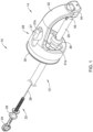
- FIG. 1 is a perspective view of a suture device 10 that may be considered as being configured for use in combination with a delivery system including a lumen that extends through the delivery system.
- the delivery system may be an endoscope having a working channel.
- the delivery system may also be a catheter. It will be appreciated that there is a change in scale on either side of the break line shown.
- the suture device 10 may be considered as including a suture translation assembly 12 that is configured to be axially translatable within the lumen of the delivery system and a distal assembly 14 that is configured to be secured to a distal end of the delivery system.
- the suture translation assembly 12 extends into the distal assembly 14 and includes a needle 16 that may be used to carry a suture as well as a distal shuttle 18 that is configured to releasably secure the needle 16.
- a member 20 may be disposed over the distal shuttle 18 and, as will be shown in subsequent Figures, is movable between a locked position in which the needle 16 is secured to the distal shuttle 18 and an unlocked position in which the needle 16 is releasable from the distal shuttle 18.
- the member 20 may be a sleeve 20.
- a user interface 22 extends proximally from the distal shuttle 18 and the sleeve 20, and may be configured to move the sleeve 20 between the locked position and the unlocked position.
- the user interface 22 may include a proximal handle 24 and a translating handle 26 that is disposed relative to the proximal handle 24.
- the proximal handle 24 may be used to move the suture device 10 proximally or distally, while the translating handle 26 may be used to move the needle 16 between the distal shuttle 18 and the distal assembly 14.
- a shaft 28 may extend distally from the proximal handle 24 to the suture translation assembly 12, and may in particular be coupled to the sleeve 20.
- the distal assembly 14 includes a body 29 having a proximal connector 30 that may be configured to be coupled to the distal end of an endoscope or other delivery system.
- the body 29 includes an arm 32 that extends to an endcap 34.
- the endcap 34 may be configured to releasably engage and disengage the needle 16.
- the endcap 34 may be configured to engage the needle 16 when the needle 16 is advanced distally into the endcap 34, and to release the needle 16 when the needle 16 is locked into the distal shuttle 18 (as will be discussed) and the distal shuttle 18 is withdrawn proximally.
- the distal assembly 14 may be considered as including a guide member 36 that may be secured to or integrally formed with the body 29, and may permit the suture translation assembly 12 to extend through the guide member 36 and to translate relative to the guide member 36.
- the body 29 may include an aperture 27 that may enable other devices to be inserted through the aperture 27.
- the aperture 27 may be configured to accommodate a side-saddled lumen attachment element.
- the aperture 27 may include one or more of a pin aperture 31a and a pin aperture 31b that may, for example, be used to mount the aforementioned side-saddled lumen attachment element, or possibly other features as well.
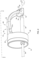
- Figure 2 and Figure 3 show the suture translation assembly 12 extended through the guide member 36 and into the distal assembly 14.
- the suture translation assembly 12 is shown in an extended position in which the needle 16 extends into the endcap 34 while in Figure 3 , the suture translation assembly 12 is shown in a retracted position in which the needle 16 has been withdrawn proximally from the endcap 34.
- the endcap 34 includes a proximal needle opening 36 that is configured to help guide the needle 16 into the proximal needle opening 36 as well as to accommodate the needle 16 when the needle 16 is advanced distally into the endcap 34.
- the proximal needle opening 36 may extend all the way through the endcap 34 while in other cases the proximal needle opening 36 may not pass all the way through the endcap 34. In some instances, as shown, the proximal needle opening 36 may be considered as being aligned with a longitudinal axis 38 of the needle 16 (as shown in Figure 3 ).
- One or more securement openings 40 may be arranged orthogonal to the proximal needle opening 36 and one or more securements 42 that are configured to be disposed within the one or more securement openings 40, and which are configured to releasably engage the distal detent (as will be discussed) of the needle 16.
- there may be a pair of securement openings 40 one on either side of the endcap 34.
- there may be a pair of securements 42 with one disposed within each of the pair of securement openings 40.
- the one or more securements 42 may be springs or coils, for example.
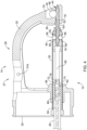
- Figure 4 is a cross-sectional view of the distal assembly 14, with the suture translation assembly 12 disposed within the distal assembly 14.
- Figure 5 is an exploded view of the suture translation assembly 12.
- the needle 16 may be considered as including a distal region 44 and a proximal region 46.
- the distal region 44 may include a distal detent 48 for releasably engaging the endcap 34 and the proximal region 46 may include a proximal detent 50 for releasably engaging the distal shuttle 18.
- the needle 16 may, as shown, include an aperture 52 for accommodating a suture line passing therethrough.
- the distal shuttle 18 may be considered as including a distal needle opening 54 that is configured to accommodate the needle 16 when the distal shuttle 18 is advanced distally over the needle 16 and that is aligned with the longitudinal axis 38 of the needle 16.
- One or more bearing ball openings 56 may be arranged orthogonal to the distal needle opening 54 such that the one or more bearing ball openings 56 align with the proximal detent 50 when the needle 16 is secured to the distal shuttle 18.
- one or more bearing balls 58 may be disposed within the one or more bearing ball openings 56 and may be configured to be disposed within the proximal detent 50 when the needle is secured to the distal shuttle 18.
- the distal shuttle 18 includes an internal void 60 and a sleeve capture member 62 that is slidingly disposed within the internal void 60.
- the sleeve capture member 62 may be coupled to a cable 64 extending distally from the user interface 22 within the shaft 28 and into a cable aperture 66 and secured via a crimp or other mechanical connection 68.
- the sleeve capture member 62 may be coupled to the sleeve 20 via a pin 70 that extends through first and second sleeve connection apertures 72, 74 and a corresponding aperture 76 extending through the sleeve capture member 62 as well as extending through the internal void 60.
- the sleeve 20 includes one or more sleeve openings 80 that may be smaller in diameter, or smaller in width, than the diameter of the one or more bearing balls 58.
- the sleeve 20 may include a pair of sleeve openings 80, corresponding to a pair of bearing ball openings 56 and a pair of bearing balls 58.
- the one or more sleeve openings 80 are misaligned with, or do not align with, the one or more bearing ball openings 56, and so the one or more bearing balls 58 engage the proximal detent 50 of the needle 16.
- the sleeve 20 prevents the one or more bearing balls 58 from being pushed out of the proximal detent 50.
- the one or more sleeve openings 80 are aligned with the one or more bearing ball openings 56. This permits the one or more bearing balls 58 to move radially out, into the one or more sleeve openings 80, a distance sufficient to permit the one or more bearing balls 58 to clear the proximal detent 50 of the needle 16 in response to a force applied to the one or more bearing balls 58 by the needle 16.
- the distal shuttle 18, and the sleeve 20, in combination provide an active connection to the needle 16 while the distal endcap 34 provides a passive connection to the needle 16. If the needle 16 is moved distally into the distal endcap 34, the distal endcap 34 will grab onto the needle 16, with the one or more securements 42 engaging the distal detent 48. If the needle 16 is subsequently moved proximally, the axial force applied overcomes any resistance provided by the one or more securements 42, and the needle 16 is able to move proximally.
- the active connection to the needle 16 provided by the distal shuttle 18 and the sleeve 20 requires action to move the sleeve 20, relative to the distal shuttle 18, between the locked position and the unlocked position.
- the user interface 22 provides a mechanism for positively moving the sleeve 20 between the locked and unlocked positions.
- Figure 7 is a perspective view of the user interface 22 and Figure 8 is a cross-sectional view along line 8-8 of Figure 7 .
- the cable 64 which extends through the shaft 28, is coupled to the translating handle 26 via a connector 90.
- the connector 90 is able to translate relative to the proximal handle 24, and thus enable the translating handle 26 to translate relative to the proximal handle 24, by translating within a void 92 formed within the proximal handle 24.
- the shaft 28 includes a coil 94. It will be appreciated that the relative position of the translating handle 26 (relative to the proximal handle 24) shown in Figures 7 and 8 corresponds to the sleeve 20 being in the locked position (as shown in Figure 6A ).
- the proximal handle 24 includes a handle portion 96.
- Figure 9A is a perspective view of the user interface 22 with the translating handle 26 shown in an intermediate position relative to the proximal handle 24 while Figure 9B is a perspective view of the user interface 22 with the translating handle 26 shown in a retracted, unlocked position.
- a user may move the translating handle 26 distally relative to the proximal handle 24, from the neutral position.
- a user may move the translating handle 26 proximally relative to the proximal handle 24, from the neutral position.
- a user has to intentionally engage the translating handle 26 in order to lock or unlock the needle 16 relative to the distal shuttle 18.
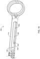
- Figure 10 is a side view of an alternate proximal handle 24a that may, for example, be used in forming the user interface 22.
- the proximal handle 24a may include a void 92a having several one or more handle detents 100 that are formed within a surface 102 of the void 92a.
- the surface 102 may include one or more distinct sections 104, 106 that provide varying frictional forces to a friction disk that may be secured within the translating handle 26 and that may interact with the surface 102 as the translating handle 26 is moved distally and proximally relative to the proximal handle 24a.
- providing varying frictional forces to a friction disk can provide feedback to an operator as to the position of the translating handle 26 relative to the proximal handle 24a, and thus provide the operator with feedback as to whether the sleeve 20 ( Figure 1 ) is in locked position, an unlocked position or an intermediate position.
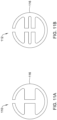
- Figures 11A and 11B provide illustrative but non-limiting examples of friction disks that may be used.
- a friction disk 110 may be seen as having a circular outer profile 116 and one or more voids or slots configured to accommodate features on the proximal handle 24a.
- a friction disk 112 may be seen as having a circular outer profile 116 and one or more voids or slots configured to accommodate features on the proximal handle 24a.
- the friction disks 110, 112 may be formed of any suitable material such as Delrin and may be dimensioned to slidingly engage an outer surface 114 of the proximal handle 24a.
- Figure 12 shows the friction disk 112 disposed about the proximal handle 24a while Figure 13 also shows a translating handle 26a in position relative to the proximal handle 24a.
- the outer profile 116 of the friction disk 112 engages into a corresponding slot 118 formed within the translating handle 26a such that as the translating handle 26a moves distally or proximally relative to the proximal handle 24a, the friction disk 112 frictionally engages the outer surface 114 of the proximal handle 24a.
- Figure 14 is a side view of a distal assembly 14a that may, for example, be usable in the suture device 10 shown in Figure 1 .
- the distal assembly 14a is similar to the distal assembly 14 shown in previous Figures, but includes a side-saddled lumen attachment element 120 that is coupled to the body 29 of the distal assembly 14a.
- the side-saddled lumen attachment element 120 may include one or two pegs 122 that fit into the pin apertures 31a and 31b (pin aperture 31a is visible in this view) and thus enable the side-saddled lumen attachment element 120 to pivot relative to the body 29 of the distal assembly 14a.
- the side-saddled lumen attachment element 120 includes a ring 124, from which the pegs 122 extend, a distal region 126 and a body 128 that in some instances has a curvature to it.
- the distal region 126 and the body 128 have a semi-circular profile in order to accommodate a lumen such as a flexible lumen 130 that may engage within the side-saddled lumen attachment element 120 via a frictional or compressive fit as shown in Figure 15 .
- the flexible lumen 130 may be polymeric or metallic.
- a polymeric lumen may, for example, be expanded to a full working dimension by extending a mandrel through the flexible lumen 130 after the flexible lumen 130 has been placed relative to the side-saddled lumen attachment element 120.
- the side-saddled attachment element 120 (and accompanying flexible lumen 130) may be used as a secondary working channel and may contain the suture used in the procedure. In some cases, it may be large enough to accommodate secondary tools for use during the procedure for tissue acquisition or manipulation allowing secondary tool use without requiring a dedicated dual-channel delivery system such as a dual channel endoscope. If desired, a dual-channel delivery system could be used to provide even more options in a procedure.
- the side-saddled attachment element 120 may have an exit port in the distal assembly 14a such that secondary tools extend along an axis suitable for tissue manipulation. This axis may cross the axis of the suture carrying element, allowing a secondary tool to pull tissue into the suture carrying element's projected path. For example, this could be used to pull tissue in line with a needle to assist in driving the needle 16 through the tissue. Maintaining tension on the suture through the side-saddled attachment element 120 may keep the suture from interfering with the procedure.
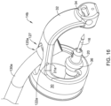
- Figure 16 is a perspective view of a distal assembly 14b that includes a shorter side-saddled lumen attachment element 120a that may be pivotally secured to the body 29 via one or more pegs 122a that extend into the pin apertures 31a, 31b.
- a lumen 130a coupled with the side-saddled lumen attachment element 120a to provide a working channel through which the suture or other tools may be extended.
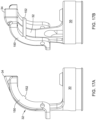
- Figure 17A and 17B are views of a tissue release mechanism 150 that may fit over the arm 32.
- the tissue release mechanism 150 may assist in a procedure by helping to remove tissue that may otherwise become stuck on the needle 16.
- the tissue release mechanism 150 may be spring-loaded to engage the needle 16, or may be separately and independently actuated.
- the tissue release mechanism 150 includes a cross-bar 152 that provides an additional surface that can push tissue off of the needle 16.
- the distal assembly 14 may be secured to a delivery device such as an endoscope.
- an attachment enabler such as a flexible silicone tube
- the side-saddled lumen attachment element 120 may be secured to the distal assembly 14.
- the suture may be passed through the needle 16, and fed back towards the user interface 22.
- the device 10 may be extended through the body to the defect site.
- the defect may require a full thickness repair, while in other cases, the defect may not pass through all of the tissue layers.
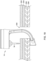
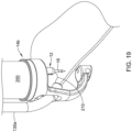
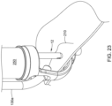
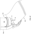
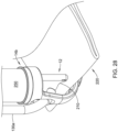
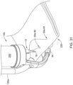
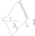
- Figures 18 through 25 provide an illustrative but non-limiting example of a full thickness tissue repair while Figures 26 through 32 provide an illustrative but non-limiting example of a partial thickness tissue repair.
- Figure 18 shows the distal assembly 14 positioned relative to a defect 200.
- the defect 200 extends through the mucosa layer 202, the submucosa layer 204, the muscularis layer 206 and the serosa layer 208.
- the distal assembly 14b is coupled to an endoscope 250, and has been positioned with a suture 210 coupled to the needle 16.
- the suture 210 may, for example, be monofilament, braided, barbed and the like.
- the suture translation element 12 has been pushed distally until the needle 16 pushes through the tissue and locks into the endcap 34 (not visible).
- the user pulls on the translating handle 26 to unlock the needle 16 and pulls the suture device 10 proximally clear of the needle 16.
- the endoscope 250 may be pushed distally to pass the needle 16 entirely through the tissue. This completes the first suture site.
- the suture device 10 may be moved to the opposite side of the defect 200, with the needle 16 still locked into the endcap 34.
- the suture 210 is allowed to advance freely to provide sufficient play to create suture site #2.
- the operator pushes the suture device 10 distally to push the tissue over the needle 16 while maintaining the translation handle 26 in an unlocked position.
- the translation handle 26 is pushed distally to lock the needle 16 into the suture translation element 12.
- the suture translation element 12 is pulled proximally to pull the rest of the needle 16 through the tissue. These steps are repeated until all suture sites are complete.
- the needle 16 may be used as an anchor for the last stitch. In some instances, the needle 16 may be biosorbable.
- Figure 26 shows the distal assembly 14 positioned relative to the defect 200, with the endcap 34 positioned between the mucosa layer 202 and the submucosa layer 204.
- injection of a suitable fluid such as saline may provide working space between the layers.
- the suture device 10 may be placed at one end of the defect 200, and a bleb 220 may be created where the tissue is doubled over on itself. With the needle 16 exposed, and with respect to Figure 28 , the suture translation element 12 may be pushed distally until the needle 16 passes through the tissue and locks into the endcap 34.
- the user pulls on the translating handle 26 to unlock the needle 16 and to pull the suture translation element 12 proximally clear of the needle 16.
- the delivery device may be pushed distally to push the needle 16 completely through the tissue. This completes suture site #1.
- the suture device 10 is moved to a new suture site, as seen in Figure 30 , with the needle 16 still locked into the endcap 34.
- Suture 210 is allowed to advance freely to provide sufficient play to create suture site #2.
- Another bleb 220 of tissue is formed. As seen in Figure 31 , the operator pushes the suture device 10 distally to push the tissue over the needle 16 while maintaining the translating handle 26 in the unlocked position.
- the translating handle 26 may be pushed distally to lock the needle 16 into the suture translation element 12.
- the suture translation element 12 then is pulled proximally to pull the needle 16 through the tissue. These steps continue until the defect 200 has been closed.
- the needle 16 may be used as an anchor for the last stitch.
- Figure 33 is a perspective view of a distal assembly 14c that may, for example, be usable in the suture device 10 shown in Figure 1 .
- the distal assembly 14c is similar to the distal assembly 14 shown in previous Figures, but includes several modifications that may be useful, particularly in bariatric revision procedures.
- a bariatric procedure commonly refers to a procedure in which the effective useful volume of a patient's stomach may be surgically reduced in order to effect long-term weight loss for the patient and may be performed laparoscopically.
- a bariatric revision procedure is a procedure, performed endoscopically, in which changes may be made to what was originally done to the patient's stomach.
- the distal assembly 14c may also be used in other suturing procedures, such as but not limited to the full tissue thickness procedure shown in Figures 18 through 25 and/or the partial tissue thickness shown in Figures 26 through 32 . These are just illustrative examples of the use of the distal assembly 14c.
- Figures 43 through 47 to be discussed subsequently, provide an example of a tangential approach useful in bariatric revision procedures.
- the distal assembly 14c may include a body 29a having a proximal connector 30a that may be configured to be coupled to the distal end of an endoscope or other delivery system, for example.
- the body 29a includes an arm 32a that extends to an endcap 34a.
- the body 29a, including the arm 32a may be similar to the body 29 and arm 32 referenced previously with respect to the distal assembly 14, the distal assembly 14a and the distal assembly 14b.
- the body 29a and the arm 32a may be adapted to accommodate thicker tissue, which may for example mean a change in the overall shape of the body 29a and/or the arm 32a relative to the body 29 and/or the arm 32.
- the distal assembly 14c may be considered as including a guide member 36a that may be secured to or integrally formed with the body 29a, and may be configured to permit a suture translation assembly (such as the suture translation assembly 12, a suture translation assembly 12a, shown in Figures 34 through 38 , or a suture translation assembly 12b, shown in Figures 39 through Figure 42 ) to extend through the guide member 36a and to translate relative to the guide member 36a.
- a suture translation assembly such as the suture translation assembly 12, a suture translation assembly 12a, shown in Figures 34 through 38 , or a suture translation assembly 12b, shown in Figures 39 through Figure 42
- the guide member 36a includes a channel 300.
- the channel 300 permits a suture to pass between the suture translation assembly 12, 12a, 12b and a working channel of the endoscope or other delivery device to which the distal assembly 14c is attached.
- the channel 300 may, for example, be designed to include a lead in that would help to align the suture with the channel 300 when passing the suture translation assembly 12, 12a, 12b through the working channel of the endoscope or other delivery device.
- the distal assembly 14c includes a guide structure 27a that is attached to or integrally formed with the body 29a.
- the guide structure 27a may instead be pivotably attached to the body 29a.
- the guide structure 27a may be configured to accommodate a polymeric tubular member attached thereof, in order to guide tools through the endoscope and into position relative to the working site.
- the guide structure 27a may be configured to accommodate a metallic tubular member attached thereto.
- the guide structure 27a and accompanying tubular member may accommodate a graspers or similar tool that allows a user to grasp tissue and pull it into position so that the needle 16 may be passed through the tissue.
- the relative position, or offset of the guide structure 27a, relative to the relative position or offset illustrated with respect to the distal assembly 14, the distal assembly 14a or the distal assembly 14b may be greater in order to provide more room for tools and/or to accommodate larger and/or thicker portions of tissue.
- the end cap 34a includes one or more securement openings 40a that may be, as can be seen, be arranged orthogonally to a proximal needle opening (not illustrated), such as the proximal needle opening 36 illustrated for example in Figure 3 .
- One or more securements 42a may correspondingly be disposed within the one or more securement openings 40a.
- the one or more securements 42a may be a coil spring that is disposed within the one or more securement openings 40a.
- the securement 42a may releasably engage a detent on the needle 16, as discussed with respect to the distal assembly 14.
- the securement opening 40a visible on the right side may have a diameter that is greater than an overall diameter of the securement 42a and the securement opening 40a may taper to a diameter on the left side (not seen) that is about the same as the diameter of the securement 42a.
- the securement 42a may be welded, soldered, adhesively secured or otherwise attached at the left side of the securement opening 40a, and may be free to move somewhat at the right side of the securement opening 40a.
- the distal assembly 14c may include an opening 302 that is orthogonal to the securement opening 40a. The opening 302 may be threaded in order to threadedly engage a set screw 304.
- the opening 302 may be offset closer to the right side of the securement opening 40a, away from the secured end of the securement 42a, such that the set screw 304 may be considered as supporting the free end of the securement 42a.
- Rotating the set screw 304 in a first direction such as clockwise, may cause the set screw 304 to translate towards the securement 42a, thereby increasing an interference between the securement 42a and the needle 16 and increasing a retentive force that can be applied to the needle 16.
- rotating the set screw in a second direction such as counter-clockwise, may cause the set screw 304 to translate away from the securement 42a, thereby decreasing the retentive force that can be applied to the needle 16. This may help to adjust for manufacturing tolerances, for example.
- the distal assembly 14c may be used in combination with the suture translation assembly 12 discussed previously with respect to Figure 5 , for example.
- the distal assembly 14c may also be used with a suture translation assembly 12a, shown in Figure 34 through Figure 38 , as well as with a suture translation assembly 12b, shown in Figure 39 through Figure 42 .
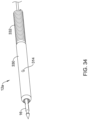
- Figure 34 is a perspective view of the suture translation assembly 12a, shown holding the needle 16, while Figure 35 is a partially exploded view of the suture translation assembly 12a.
- the suture translation assembly 12a includes an inner member 310 that hold the needle 16.
- a locking member 312 is slidingly disposed over the inner member 310.
- the inner member 310 includes a pin 314 that extends radially outwardly from the inner member 310 and extends through a corresponding slot 316 that is formed in the locking member 312.
- the pin 314 serves to prevent relative rotation between the inner member 310 and the locking member 312.
- the pin 314 also serves to limit translation of the locking member 312 relative to the inner member 310.
- a control member 318 is secured relative to a proximal end 320 of the locking member 312, and extends distally to a handle such as the translating handle 26 ( Figure 1 ).
- the locking member 312 may be translated distally and/or proximally relative to the inner member 310.
- the suture translation assembly 12a includes an outer sleeve 330 that may be pinned via the pin 314 to the inner member 310.
- the outer sleeve 330 may be coupled with a coil 332, for example. In some cases, the outer sleeve 330 may be a single tubular member.
- the outer sleeve 330 may actually include one or more of an outer sleeve 334, a slotted sleeve 336, and an inner outer sleeve 338.
- the slotted sleeve 336 may be configured to permit a suture to pass therethrough. This is merely illustrative, and is not intended to be limiting in any fashion.
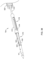
- the inner member 310 includes several arms 322 that, as seen in Figure 36 , which shows the distal portion of the inner member 310, include curved tabs 324 that are configured to engage corresponding detents within the needle 16. While a total of four arms 322 are shown, it will be appreciated that the inner member 310 may include any number of arms 322. It will be appreciated that the arms 322 are relatively long in length, and as a result may be considered as being relatively flexible. With the locking member 312 extended distally into a locking configuration, as shown for example in Figure 37 , the locking member 312 prevents outward movement of the arms 322. As a result, the curved tabs 324 remain in engagement with the corresponding detents of the needle 16, and the needle 16 remains locked to the suture translation assembly 12a.
- the arms 322 are free to move radially outwardly, thereby releasing the curved tabs 324 from the detents in the needle 16, and allowing the needle 16 to move distally relative to the inner member 310.
- Figure 39 is a perspective view of a suture translation assembly 12b that may be used in combination with any of the distal assembly 14, the distal assembly 14a, the distal assembly 14b and/or the distal assembly 14c.
- Figure 40 is a perspective view of the suture translation assembly 12b with outer portions such as an outer sleeve 350 ( Figure 39 ) removed to reveal an inner member 340 that holds a needle 16a.
- the outer sleeve 350 may be a single tubular member.
- the outer sleeve 350 may include several elements, such as described with respect to the outer sleeve 330 ( Figure 35 ).
- the needle 16a has a distal detent 342 and a proximal detent 344 (visible in Figure 41 ) that are shaped differently than the corresponding detents in the needle 16.
- the suture translation assembly 12b includes a locking member 346 that is slidingly disposable relative to the inner member 340.
- the pin 352 is attached to the inner member 340 and extends through a corresponding slot 354 formed in the locking member 342.
- the pin 352 limits translation of the locking member 342 relative to the inner member 340, and also prevents relative rotational movement of the locking member 342.
- the locking member 342 is secured to the control member 318, which extends distally to a handle such as the translating handle 26 ( Figure 1 ). As a result, the locking member 342 may be translated distally and/or proximally relative to the inner member 340.
- the outer sleeve 350 may define a slot 370 including an axially extending slot portion 372 and a shorter radially extending slot portion 374.
- the axially extending slot portion 372 permits the pin 352 to move within the axially extending slot portion 372 in order to permit the needle 16a to be fully withdrawn into the suture translation assembly 12b for advancement through an endoscope or other delivery device.
- the inner member 340 and the locking member 342 may be advanced distally through the outer sleeve 350 until the pin 352 aligns with the radially extending slot portion 374.
- the pin 352 may be rotated into position within the radially extending slot portion 374 so that the locking member 342 may be translated relative to the inner member 340.
- the locking member 342 includes a pair of arms 358 that extend distally from the locking member 342.
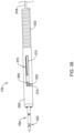
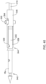
- the arms 358 include tabs 360 that, when the suture translation assembly 12b is in a locked configuration as shown in Figures 40 and 41 , the tabs 360 extend through slots 362 formed within the inner member 340. As a result, the tabs 360 are able to extend through the slots 362 and engage the proximal detent 344 of the needle 16a. While a pair of arms 358 are illustrated, it will be appreciated that the locking member 342 may include any number of arms 358, and of course a corresponding number of slots 362.
- the locking member 342 may be moved distally relative to the inner member 340.
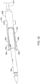
- the tabs 360 have moved out of the slots 362 (only one slot 362 is seen), and the needle 16a is free to move relative to the suture translation assembly 12b.
- angled surfaces 364 push against the slots 362 and are moved outwardly.
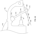
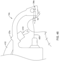
- Figures 43 through 47 provide an illustrative but non-limiting example of the distal assembly 14c being used to perform a tissue repair using a tangential approach.
- a tangential approach may be used, for example, when repairing a larger wound that requires suturing through thicker or more tissue.
- Bariatric revision procedures are an example of a procedure that would benefit from a tangential approach.
- the distal assembly 14c in performing the illustrated procedure, may be secured to the distal end of an endoscope or other delivery device, and may be used in combination with any of the suture translation assembly 12, the suture translation assembly 12a and/or the suture translation assembly 12b, as desired.
- Figure 43 shows a defect 400 within tissue 402.
- the defect 400 may include a remaining open portion 404 along a staple or suture line 405.
- a portion of the defect 400 has already been closed using staples 406, and in some cases the remaining open portion 404 may be positioned such that stapling is either inappropriate or difficult to perform.
- a tissue grasping tool 410 extends through a tubular member 412 that is secured relative to the guide structure 27a, and may be positioned such that the tissue grasping tool 410 is able to grasp tissue 414 proximate one side of the remaining open portion 404 of the defect 400, and the tissue 414 may be pulled upward by retracting the tissue grasping tool 410, as denoted by an arrow 416. As the tissue 414 is pulled upward, as noted in Figure 45 , suturing may begin. In Figure 46 , it can be seen that the needle 16 has been passed through the tissue 414 and has been grasped by the end cap 34a, thereby pulling a suture 420 through the tissue 414.
- the suture 420 now extends through the tissue 414 on a first side 430 of the remaining open portion 404 of the defect 400.
- the suturing process may continue by repeating the aforementioned steps on the second side 432 of the remaining open portion 404 of the defect 400.
- the devices described herein may include any suitable polymeric material, including biocompatible materials such as polyurethane or silicone.
- polytetrafluoroethylene PTFE
- ETFE ethylene tetrafluoroethylene
- FEP fluorinated ethylene propylene
- POM polyoxymethylene
- polyether block ester polyurethane (for example, Polyurethane 85A), polypropylene (PP), polyvinylchloride (PVC), polyether-ester (for example, ARNITEL ® available from DSM Engineering Plastics), ether or ester based copolymers (for example, butylene/poly(alkylene ether) phthalate and/or other polyester elastomers such as HYTREL ® available from DuPont), polyamide (for example, DURETHAN ® available from Bayer or CRISTAMID ® available from Elf Atochem), elastomeric polyamides, block polyamide/ethers, polyether block amide (PEBA, for example available under the trade name PEBAX
Landscapes
- Health & Medical Sciences (AREA)
- Life Sciences & Earth Sciences (AREA)
- Surgery (AREA)
- Molecular Biology (AREA)
- General Health & Medical Sciences (AREA)
- Biomedical Technology (AREA)
- Heart & Thoracic Surgery (AREA)
- Medical Informatics (AREA)
- Nuclear Medicine, Radiotherapy & Molecular Imaging (AREA)
- Animal Behavior & Ethology (AREA)
- Engineering & Computer Science (AREA)
- Public Health (AREA)
- Veterinary Medicine (AREA)
- Physics & Mathematics (AREA)
- Biophysics (AREA)
- Optics & Photonics (AREA)
- Pathology (AREA)
- Radiology & Medical Imaging (AREA)
- Surgical Instruments (AREA)
Abstract
Description
- This application claims priority to
U.S. Provisional Application Serial No. 62/461,969, filed February 22, 2017 U.S. Provisional Application Serial No. 62/477,250, filed March 27, 2017 - The disclosure is directed to devices for suturing tissue and more particularly to devices that work with an endoscope or similar device for endoscopically suturing tissue.
- A variety of endoscopic treatments may result in defects (or wounds) that are too large for hemostasis clips to easily bridge and thus help to close the defect. Examples of such endoscopic treatments include removal of large lesions, tunneling under the mucosal layer, full thickness removal of tissue, treating other organs by passing outside of the gastrointestinal tract, and repair of post-surgical issues such as post-surgical leaks, failing surgical staple lines and anastomotic leaks. Endoscopic treatments also include bariatric revision procedures. Of the known devices and methods for endoscopically closing large defects, each has certain advantages and disadvantages.
- The disclosure is directed to several alternative designs, materials and methods of devices for endoscopically closing large defects. In an example, a suture device for use in combination with a delivery system including a lumen extending through the delivery system includes a suture translation assembly that is configured to be axially translatable within the lumen of the delivery system and a distal assembly that is configured to be securable to the distal end of the delivery system. In some cases, the suture translation assembly may be considered to be an active suture translation assembly while the distal assembly may be considered to be a passive distal assembly. The suture translation assembly may move relative to the delivery system while the distal assembly remains stationary relative to the delivery system. The suture translation assembly includes a needle usable to carry a suture, a distal shuttle that is configured to releasably secure the needle. A user interface extends proximally from the distal shuttle and is configured to releasably secure the needle. The distal assembly includes an endcap that is configured to releasably engage and disengage the needle, the endcap configured to engage the needle when the needle is advanced distally into the endcap, and to release the needle when the needle is locked to the distal shuttle and the distal shuttle is withdrawn proximally. A guide member is configured to permit the suture translation assembly to extend through the guide member and to translate relative to the guide member.
- Alternatively or additionally, the needle may include a distal region and a proximal region, the distal region including a distal detent for releasably engaging the endcap, the proximal region including a proximal detent for releasably engaging the distal shuttle.
- Alternatively or additionally, the endcap may include a proximal needle opening that is configured to accommodate the needle when the needle is advanced distally into the endcap, the proximal needle opening aligned with a longitudinal axis of the needle, one or more securement openings that are arranged orthogonal to the proximal needle opening and one or more securements that are disposed within the securement openings and are configured to releasably engage the distal detent of the needle.
- Alternatively or additionally, the one or more securement openings may comprise an aperture that tapers from a first diameter that is larger than a diameter of a securement disposed therein to a second diameter that is about equal in diameter to the diameter of the securement.
- Alternatively or additionally, the distal assembly further includes a set screw opening that is orthogonal to the securement opening and a set screw threadedly engaged in the set screw opening such that the set screw adjustably engages the securement.
- Alternatively or additionally, the set screw opening is disposed closer to the first diameter than to the second diameter.
- Alternatively or additionally, the one or more securements may be spring-loaded.
- Alternatively or additionally, the guide member may include a channel cut longitudinally into the guide member in order to accommodate a suture therethrough.
- Alternatively or additionally, the distal shuttle may include a distal needle opening that is configured to accommodate the needle when the distal shuttle is advanced distally over the needle, the distal needle opening aligned with a longitudinal axis of the needle, one or more bearing ball openings that are arranged orthogonal to the distal needle opening such that the one or more bearing ball openings align with the proximal detent when the needle is secured to the distal shuttle and one or more bearing balls that are disposed within the one or more bearing ball openings and disposable within the proximal detent when the needle is secured to the distal shuttle.
- Alternatively or additionally, the user interface may further include a member that is disposable over the distal shuttle and is movable between a locked position in which the needle is secured to the distal shuttle and an unlocked position in which the needle is releasable from the distal shuttle. The member may include one or more member openings smaller in diameter than the one or more bearing balls. When in the locked position, the one or more member openings may be misaligned with the one or more bearing ball openings such that the one or more bearing balls engage the proximal detent of the needle and when in the unlocked position, the one or more member openings may be aligned with the one or more bearing ball openings such that the one or more bearing balls can move radially outward a distance sufficient to permit the one or more bearing balls to clear the proximal detent of the needle.
- Alternatively or additionally, the user interface may include a proximal handle, a translating handle disposed relative to the proximal handle and a cable extending distally from the translating handle to the member. Axial movement of the translating handle relative to the proximal handle may cause the member to translate relative to the distal shuttle.
- Alternatively or additionally, the distal shuttle may further include an internal void and a member capture element slidingly disposed within the internal void, the cable secured to the member capture element and the member capture element secured to the member, such that axial movement of the translating handle relative to the proximal handle causes the member capture element to translate within the internal void and thus permit the member to translate relative to the distal shuttle.
- Alternatively or additionally, the member may further include one or more member capture apertures disposed within the sleeve, and the member capture member may be secured to the member via a pin extending through the member capture apertures and through the member capture member.
- Alternatively or additionally, the translating handle may have a neutral position.
- Alternatively or additionally, moving the translating handle distally from the neutral position may cause the member to move to the locked position and moving the translating handle proximally from the neutral position may cause the member to move to the unlocked position.
- Alternatively or additionally, the delivery system may include an endoscope and the lumen may be a working channel of the endoscope.
- Alternatively or additionally, the distal shuttle may include an inner member that is configured to accommodate the needle and a locking member that is slidingly disposed over the inner member, the locking member movable between a locked configuration in which the needle is secured to the distal shuttle and an unlocked configuration in which the needle is released from the distal shuttle.
- Alternatively or additionally, the inner member may include a plurality of arms that releasably engage a proximal detent in the needle.
- Alternatively or additionally, when in the locked configuration, the locking member is in a position in which the locking member prevents radially outward movement of the plurality of arms, and when in the unlocked configuration, the locking member has been withdrawn proximally relative to the inner member such that the arms are able to move radially outwardly.
- Alternatively or additionally, the locking member is coupled to a control member that extends proximally and allows the locking member to be translated distally and proximally relative to the inner member.
- Alternatively or additionally, the distal shuttle may include an inner member that is configured to accommodate the needle and a locking member that is slidingly disposed over the inner member, the inner member including one or more slots, the locking member including one or more tabs that releasably extend through the slots in order to engage the proximal detent of the needle.
- Alternatively or additionally, the distal shuttle is movable between a locked configuration in which the one or more tabs of the locking member extend through the one or more slots of the inner member and an unlocked configuration in which the tabs are forced distally of the one or more slots, thereby releasing the needle.
- Alternatively or additionally, the inner member further includes a pin extending radially outwardly from the inner member, and the locking member further includes an elongate slot to accommodate the pin, the pin and the elongate slot in combination limiting relative translation between the inner member and the locking member.
- In another example, a suture device for use in combination with an endoscope having a working channel and a distal end includes a translation assembly configured to be axially translatable within the working channel and a distal assembly configured to be securable to the distal end of the endoscope. The translation assembly includes a needle that is configured to carry a suture, a distal shuttle that is configured to releasably secure the needle and a sleeve that is disposable over the distal shuttle and is movable between a locked position in which the needle is secured to the distal shuttle and an unlocked position in which the needle is releasable from the distal shuttle. The distal assembly includes an endcap that is configured to engage the needle when the needle is advanced distally into the endcap and to release the needle when the needle is locked to the distal shuttle and the distal shuttle is withdrawn proximally.
- Alternatively or additionally, the translation assembly may further include a user interface that extends proximally from the distal shuttle and sleeve and is configured to enable a user to move the sleeve between the locked position and the unlocked position.
- Alternatively or additionally, the user interface may include a proximal handle and a translating handle that is disposed relative to the proximal handle and movable both distally and proximally from a neutral position and a cable extending distally from the translating handle to the sleeve. Axial movement of the translating handle relative to the proximal handle may cause the sleeve to translate relative to the distal shuttle.
- Alternatively or additionally, moving the translating handle distally from the neutral position may cause the sleeve to move to the locked position and moving the translating handle proximally from the neutral position may cause the sleeve to move to the unlocked position.
- Alternatively or additionally, translating the proximal handle distally may advance the distal shuttle and thus the needle towards the endcap and translating the proximal handle distally may withdraw the distal shuttle and thus the needle proximally away from the endcap.
- Alternatively or additionally, the suture device may further include a flexible silicone tube that is configured to secure the distal assembly to the distal end of the endoscope.
- Alternatively or additionally, the distal assembly may further comprise a side-saddled lumen attachment element that is configured to provide a side lumen extending through an aperture in the body of the distal assembly.
- Alternatively or additionally, the side-saddled lumen attachment element may be pivotally attached to the aperture in the body of the distal assembly.
- Alternatively or additionally, the distal assembly may further comprise a tissue release mechanism that may be pivotally secured relative to the distal assembly.
- Alternatively or additionally, the distal assembly may be spring-loaded or actuated via a separate control wire.
- Alternatively or additionally, the user interface may include a friction disk that is disposed between the proximal handle and the translating handle such that the friction disk resists relative movement between the proximal handle and the translating handle.
- In another example, a suture device configured to be useable with a single channel endoscope may include an axially translatable needle assembly that includes a needle configured to carry a suture and that is configured to be translatable within the single channel and a distal assembly configured to be securable to the distal end of the single channel endoscope such that the axially translatable needle assembly can engage the distal assembly to pass the needle back and forth between engagement with the distal shuttle and engagement with the distal assembly. The translatable needle assembly includes a distal shuttle configured to releasably secure the needle and a sleeve that is disposable over the distal shuttle and is movable between a locked position in which the needle is secured to the distal shuttle and an unlocked position in which the needle is releasable from the distal shuttle. A cable is coupled with the distal shuttle and the sleeve and coaxially aligned with the distal shuttle and the sleeve. The suture device includes a proximal handle and a translating handle that is disposed relative to the proximal handle and secured to the cable and that is translatable to cause the sleeve to move between the locked position and the unlocked position.
- Alternatively or additionally, translating the proximal handle distally may advance the distal shuttle and thus the needle towards the distal assembly and translating the proximal handle distally may withdraw the distal shuttle and thus the needle proximally away from the distal assembly.
- The above summary of some embodiments is not intended to describe each disclosed embodiment or every implementation of the present disclosure. The Figures, and Detailed Description, which follow, more particularly exemplify these embodiments.
- The disclosure may be more completely understood in consideration of the following description of in connection with the accompanying drawings, in which:
-
Figure 1 is a perspective view of an illustrative suture device in accordance with an example of the disclosure; -
Figure 2 is a perspective view of a distal assembly forming part of the illustrative suture device ofFigure 1 , shown in an extended position; -
Figure 3 is a perspective view of the distal assembly ofFigure 2 , shown in a retracted position; -
Figure 4 is a cross-sectional view of the distal assembly ofFigure 2 , taken along the line 4-4; -
Figure 5 is an exploded view of a portion of a suture translation assembly forming part of the illustrative suture device ofFigure 1 ; -
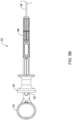
Figure 6A is a side view of a distal shuttle and a member forming part of the suture translation assembly, with the member shown extended in a locked position; -
Figure 6B is a side view of the distal shuttle and the member ofFigure 6A , with the member shown retracted in an unlocked position; -
Figure 7 is a perspective view of a handle portion of a suture translation assembly forming part of the illustrative suture device ofFigure 1 ; -
Figure 8 is a cross-sectional view of the handle portion ofFigure 7 , taken along the line 8-8; -
Figure 9A is a perspective view of the handle portion ofFigure 7 , shown in an intermediate position; -
Figure 9B is a perspective view of the handle portion ofFigure 8 , shown in a retracted, unlocked position; -
Figure 10 is a perspective view of a proximal handle in accordance with an example of the disclosure; -
Figures 11A and 11B are front views of friction disks usable with the proximal handle ofFigure 10 ; -
Figure 12 is a perspective view of the proximal handle ofFigure 10 in combination with the friction disk ofFigure 11B ; -
Figure 13 is a partial cross-sectional perspective view of the assembly ofFigure 12 in combination with a translating handle in accordance with an example of the disclosure; -
Figure 14 is a side view of a distal assembly usable in the suture device ofFigure 1 in accordance with an example of the disclosure; -
Figure 15 is a side view of the distal assembly ofFigure 14 in combination with an attached flexible lumen; -
Figure 16 is a side view of a distal assembly usable in the suture device ofFigure 1 , shown with an attached lumen, in accordance with an example of the disclosure; -
Figure 17A and 17B are views of a tissue release mechanism that may be used in combination with the distal assemblies ofFigures 1 and14 in accordance with an example of the disclosure; -
Figures 18 through 25 illustrate use of a suture device in a full thickness procedure in accordance with an example of the disclosure; -
Figures 26 through 32 illustrate use of a suture device in a partial thickness procedure in accordance with an example of the disclosure; -
Figure 33 is a perspective view of a distal assembly usable in the suture device ofFigure 1 in accordance with an example of the disclosure; -
Figure 34 is a perspective view of a suture translation assembly usable in the suture device ofFigure 1 in accordance with an example of the disclosure; -
Figure 35 is a partially exploded perspective view of the suture translation assembly ofFigure 34 in accordance with an example of the disclosure; -
Figure 36 is a perspective view of an inner member forming a portion of the suture translation assembly ofFigure 34 in accordance with an example of the disclosure: -
Figure 37 is a perspective view of a portion of the suture translation assembly ofFigure 34 , shown in a locked configuration in accordance with an example of the disclosure; -
Figure 38 is a perspective view of a portion of the suture translation assembly ofFigure 34 , shown in an unlocked configuration in accordance with an example of the disclosure; -
Figure 39 is a perspective view of a suture translation assembly usable in the suture device ofFigure 1 in accordance with an example of the disclosure; -
Figure 40 is a perspective view of the suture translation assembly ofFigure 39 , shown with some elements removed to show internal structure, with the suture translation assembly shown in a locked configuration in accordance with an example of the disclosure; -
Figure 41 is a side view of a portion of the suture translation assembly ofFigure 39 , showing how a locking member engages an inner member of the suture translation assembly and a needle in the locked configuration as shown inFigure 40 and in accordance with an example of the disclosure; -
Figure 42 is a perspective view of the suture translation assembly ofFigure 39 , shown in an unlocked configuration in accordance with an example of the disclosure; and -
Figures 43 through 47 illustrate use of a suture device in a tangential approach that may be used in suturing thicker tissue and/or larger wounds such as those encountered during a bariatric revision procedure in accordance with an example of the disclosure. - While the disclosure is amenable to various modifications and alternative forms, specifics thereof have been shown by way of example in the drawings and will be described in detail. It should be understood, however, that the intention is not to limit the invention to the particular embodiments described. On the contrary, the intention is to cover all modifications, equivalents, and alternatives falling within the spirit and scope of the disclosure.
- For the following defined terms, these definitions shall be applied, unless a different definition is given in the claims or elsewhere in this specification.
- Definitions of certain terms are provided below and shall be applied, unless a different definition is given in the claims or elsewhere in this specification.
- All numeric values are herein assumed to be modified by the term "about", whether or not explicitly indicated. The term "about" generally refers to a range of numbers that one of skill in the art would consider equivalent to the recited value (i.e., having the same function or result). In many instances, the term "about" may be indicative as including numbers that are rounded to the nearest significant figure.
- The recitation of numerical ranges by endpoints includes all numbers within that range (e.g., 1 to 5 includes 1, 1.5, 2, 2.75, 3, 3.80, 4, and 5).
- Although some suitable dimensions, ranges and/or values pertaining to various components, features and/or specifications are disclosed, one of skill in the art, incited by the present disclosure, would understand desired dimensions, ranges and/or values may deviate from those expressly disclosed.
- As used in this specification and the appended claims, the singular forms "a," "an," and "the" include or otherwise refer to singular as well as plural referents, unless the content clearly dictates otherwise. As used in this specification and the appended claims, the term "or" is generally employed to include "and/or," unless the content clearly dictates otherwise.
- The following detailed description should be read with reference to the drawings in which similar elements in different drawings are numbered the same. The detailed description and the drawings, which are not necessarily to scale, depict illustrative embodiments and are not intended to limit the scope of the disclosure. The illustrative embodiments depicted are intended only as exemplary. Selected features of any illustrative embodiment may be incorporated into an additional embodiment unless clearly stated to the contrary.
- The disclosure pertains to devices that are configured to be used in combination with an endoscope or a similar delivery device for closing wounds within the body. In some instances, the suture devices described herein may be configured such that they may be used within a single working or available channel of an endoscope, and in some cases may be operated by a single individual, although in some cases a second individual may be involved. In some cases, the suture devices described herein may be considered as operating along a single line of operation. The device itself may be translatable distally and proximally within a working channel, and a handle portion may itself be translatable distally and proximally along the same line of operation in locking and unlocking a needle to be able to pass the needle back and forth between an active portion of the suture device and a passive portion of the suture device. The device may be configured to enable the needle to be selectively locked into either of a more distal position or a more proximal position, and the device may itself be translated distally or proximally with the needle locked in place in order to move the needle, and hence a suture, relative to the tissue being repaired.
-
Figure 1 is a perspective view of asuture device 10 that may be considered as being configured for use in combination with a delivery system including a lumen that extends through the delivery system. For example, the delivery system may be an endoscope having a working channel. The delivery system may also be a catheter. It will be appreciated that there is a change in scale on either side of the break line shown. In some cases, thesuture device 10 may be considered as including asuture translation assembly 12 that is configured to be axially translatable within the lumen of the delivery system and adistal assembly 14 that is configured to be secured to a distal end of the delivery system. Thesuture translation assembly 12 extends into thedistal assembly 14 and includes aneedle 16 that may be used to carry a suture as well as adistal shuttle 18 that is configured to releasably secure theneedle 16. - A
member 20 may be disposed over thedistal shuttle 18 and, as will be shown in subsequent Figures, is movable between a locked position in which theneedle 16 is secured to thedistal shuttle 18 and an unlocked position in which theneedle 16 is releasable from thedistal shuttle 18. In some cases, for example, themember 20 may be asleeve 20. Auser interface 22 extends proximally from thedistal shuttle 18 and thesleeve 20, and may be configured to move thesleeve 20 between the locked position and the unlocked position. In some cases, as shown, theuser interface 22 may include aproximal handle 24 and a translatinghandle 26 that is disposed relative to theproximal handle 24. In some cases, as will be described, theproximal handle 24 may be used to move thesuture device 10 proximally or distally, while the translatinghandle 26 may be used to move theneedle 16 between thedistal shuttle 18 and thedistal assembly 14. Ashaft 28 may extend distally from theproximal handle 24 to thesuture translation assembly 12, and may in particular be coupled to thesleeve 20. - In some cases, the
distal assembly 14 includes abody 29 having aproximal connector 30 that may be configured to be coupled to the distal end of an endoscope or other delivery system. Thebody 29 includes anarm 32 that extends to anendcap 34. As will be discussed, theendcap 34 may be configured to releasably engage and disengage theneedle 16. In some cases, for example, theendcap 34 may be configured to engage theneedle 16 when theneedle 16 is advanced distally into theendcap 34, and to release theneedle 16 when theneedle 16 is locked into the distal shuttle 18 (as will be discussed) and thedistal shuttle 18 is withdrawn proximally. Thedistal assembly 14 may be considered as including aguide member 36 that may be secured to or integrally formed with thebody 29, and may permit thesuture translation assembly 12 to extend through theguide member 36 and to translate relative to theguide member 36. In some cases, thebody 29 may include anaperture 27 that may enable other devices to be inserted through theaperture 27. In some instances, as will be discussed with respect to subsequent Figures, theaperture 27 may be configured to accommodate a side-saddled lumen attachment element. In some cases, theaperture 27 may include one or more of apin aperture 31a and apin aperture 31b that may, for example, be used to mount the aforementioned side-saddled lumen attachment element, or possibly other features as well. -
Figure 2 andFigure 3 show thesuture translation assembly 12 extended through theguide member 36 and into thedistal assembly 14. InFigure 2 , thesuture translation assembly 12 is shown in an extended position in which theneedle 16 extends into theendcap 34 while inFigure 3 , thesuture translation assembly 12 is shown in a retracted position in which theneedle 16 has been withdrawn proximally from theendcap 34. In some cases, as can be seen, theendcap 34 includes aproximal needle opening 36 that is configured to help guide theneedle 16 into theproximal needle opening 36 as well as to accommodate theneedle 16 when theneedle 16 is advanced distally into theendcap 34. In some cases, theproximal needle opening 36 may extend all the way through theendcap 34 while in other cases theproximal needle opening 36 may not pass all the way through theendcap 34. In some instances, as shown, theproximal needle opening 36 may be considered as being aligned with alongitudinal axis 38 of the needle 16 (as shown inFigure 3 ). - One or
more securement openings 40 may be arranged orthogonal to theproximal needle opening 36 and one or more securements 42 that are configured to be disposed within the one ormore securement openings 40, and which are configured to releasably engage the distal detent (as will be discussed) of theneedle 16. In some cases, there may be a pair ofsecurement openings 40, one on either side of theendcap 34. In some cases, there may be a pair ofsecurements 42, with one disposed within each of the pair ofsecurement openings 40. In some cases, while shown schematically, the one or more securements 42 may be springs or coils, for example. -
Figure 4 is a cross-sectional view of thedistal assembly 14, with thesuture translation assembly 12 disposed within thedistal assembly 14.Figure 5 is an exploded view of thesuture translation assembly 12. Theneedle 16 may be considered as including adistal region 44 and aproximal region 46. In some cases, thedistal region 44 may include adistal detent 48 for releasably engaging theendcap 34 and theproximal region 46 may include aproximal detent 50 for releasably engaging thedistal shuttle 18. Theneedle 16 may, as shown, include anaperture 52 for accommodating a suture line passing therethrough. - In some cases, the
distal shuttle 18 may be considered as including adistal needle opening 54 that is configured to accommodate theneedle 16 when thedistal shuttle 18 is advanced distally over theneedle 16 and that is aligned with thelongitudinal axis 38 of theneedle 16. One or morebearing ball openings 56 may be arranged orthogonal to thedistal needle opening 54 such that the one or morebearing ball openings 56 align with theproximal detent 50 when theneedle 16 is secured to thedistal shuttle 18. In some cases, one ormore bearing balls 58 may be disposed within the one or morebearing ball openings 56 and may be configured to be disposed within theproximal detent 50 when the needle is secured to thedistal shuttle 18. - In some cases, the
distal shuttle 18 includes aninternal void 60 and asleeve capture member 62 that is slidingly disposed within theinternal void 60. In some cases, thesleeve capture member 62 may be coupled to acable 64 extending distally from theuser interface 22 within theshaft 28 and into acable aperture 66 and secured via a crimp or othermechanical connection 68. In some cases, thesleeve capture member 62 may be coupled to thesleeve 20 via apin 70 that extends through first and secondsleeve connection apertures aperture 76 extending through thesleeve capture member 62 as well as extending through theinternal void 60. As thecable 64 is operably coupled to the translating handle 26 (as will be discussed), it will be appreciated that moving the translatinghandle 26 distally or proximally relative to theproximal handle 24 causes a corresponding distal or proximal movement of thesleeve 20 relative to thedistal shuttle 18. - In some cases, the
sleeve 20 includes one ormore sleeve openings 80 that may be smaller in diameter, or smaller in width, than the diameter of the one ormore bearing balls 58. In some cases, thesleeve 20 may include a pair ofsleeve openings 80, corresponding to a pair of bearingball openings 56 and a pair of bearingballs 58. When thesleeve 20 is in the locked position, as shown for example inFigure 6A , the one ormore sleeve openings 80 are misaligned with, or do not align with, the one or morebearing ball openings 56, and so the one ormore bearing balls 58 engage theproximal detent 50 of theneedle 16. Thesleeve 20 prevents the one ormore bearing balls 58 from being pushed out of theproximal detent 50. - Conversely, when the
sleeve 20 is in the unlocked position, as shown for example inFigure 6B , the one ormore sleeve openings 80 are aligned with the one or morebearing ball openings 56. This permits the one ormore bearing balls 58 to move radially out, into the one ormore sleeve openings 80, a distance sufficient to permit the one ormore bearing balls 58 to clear theproximal detent 50 of theneedle 16 in response to a force applied to the one ormore bearing balls 58 by theneedle 16. With reference toFigure 4 , while thesuture translation assembly 12 is shown advanced into thedistal assembly 14, thesleeve 20 is in the unlocked position relative to thedistal shuttle 18, and thus the one ormore bearing balls 58 may be seen as extending partially into the one ormore sleeve openings 80. - In some cases, it will be appreciated that the
distal shuttle 18, and thesleeve 20, in combination, provide an active connection to theneedle 16 while thedistal endcap 34 provides a passive connection to theneedle 16. If theneedle 16 is moved distally into thedistal endcap 34, thedistal endcap 34 will grab onto theneedle 16, with the one or more securements 42 engaging thedistal detent 48. If theneedle 16 is subsequently moved proximally, the axial force applied overcomes any resistance provided by the one or more securements 42, and theneedle 16 is able to move proximally. In contrast, the active connection to theneedle 16 provided by thedistal shuttle 18 and thesleeve 20, however, requires action to move thesleeve 20, relative to thedistal shuttle 18, between the locked position and the unlocked position. Theuser interface 22 provides a mechanism for positively moving thesleeve 20 between the locked and unlocked positions. -
Figure 7 is a perspective view of theuser interface 22 andFigure 8 is a cross-sectional view along line 8-8 ofFigure 7 . Thecable 64, which extends through theshaft 28, is coupled to the translatinghandle 26 via aconnector 90. Theconnector 90 is able to translate relative to theproximal handle 24, and thus enable the translatinghandle 26 to translate relative to theproximal handle 24, by translating within a void 92 formed within theproximal handle 24. In some cases, theshaft 28 includes acoil 94. It will be appreciated that the relative position of the translating handle 26 (relative to the proximal handle 24) shown inFigures 7 and8 corresponds to thesleeve 20 being in the locked position (as shown inFigure 6A ). In some cases, theproximal handle 24 includes ahandle portion 96. -
Figure 9A is a perspective view of theuser interface 22 with the translatinghandle 26 shown in an intermediate position relative to theproximal handle 24 whileFigure 9B is a perspective view of theuser interface 22 with the translatinghandle 26 shown in a retracted, unlocked position. Accordingly, to move thesleeve 20 into the locked position, a user may move the translatinghandle 26 distally relative to theproximal handle 24, from the neutral position. To move thesleeve 20 into the unlocked position, a user may move the translatinghandle 26 proximally relative to theproximal handle 24, from the neutral position. In some cases, a user has to intentionally engage the translatinghandle 26 in order to lock or unlock theneedle 16 relative to thedistal shuttle 18. -
Figure 10 is a side view of an alternateproximal handle 24a that may, for example, be used in forming theuser interface 22. In some cases, theproximal handle 24a may include a void 92a having several one or more handle detents 100 that are formed within asurface 102 of the void 92a. In some cases, thesurface 102 may include one or moredistinct sections 104, 106 that provide varying frictional forces to a friction disk that may be secured within the translatinghandle 26 and that may interact with thesurface 102 as the translatinghandle 26 is moved distally and proximally relative to theproximal handle 24a. In some cases, providing varying frictional forces to a friction disk can provide feedback to an operator as to the position of the translatinghandle 26 relative to theproximal handle 24a, and thus provide the operator with feedback as to whether the sleeve 20 (Figure 1 ) is in locked position, an unlocked position or an intermediate position. -
Figures 11A and 11B provide illustrative but non-limiting examples of friction disks that may be used. InFigure 11A , afriction disk 110 may be seen as having a circularouter profile 116 and one or more voids or slots configured to accommodate features on theproximal handle 24a. Similarly, inFigure 11B , afriction disk 112 may be seen as having a circularouter profile 116 and one or more voids or slots configured to accommodate features on theproximal handle 24a. Thefriction disks outer surface 114 of theproximal handle 24a.Figure 12 shows thefriction disk 112 disposed about theproximal handle 24a whileFigure 13 also shows a translatinghandle 26a in position relative to theproximal handle 24a. As can be seen for example inFigure 13 , theouter profile 116 of thefriction disk 112 engages into acorresponding slot 118 formed within the translatinghandle 26a such that as the translatinghandle 26a moves distally or proximally relative to theproximal handle 24a, thefriction disk 112 frictionally engages theouter surface 114 of theproximal handle 24a. -
Figure 14 is a side view of adistal assembly 14a that may, for example, be usable in thesuture device 10 shown inFigure 1 . Thedistal assembly 14a is similar to thedistal assembly 14 shown in previous Figures, but includes a side-saddledlumen attachment element 120 that is coupled to thebody 29 of thedistal assembly 14a. In some cases, the side-saddledlumen attachment element 120 may include one or twopegs 122 that fit into thepin apertures pin aperture 31a is visible in this view) and thus enable the side-saddledlumen attachment element 120 to pivot relative to thebody 29 of thedistal assembly 14a. In some cases, the side-saddledlumen attachment element 120 includes aring 124, from which thepegs 122 extend, adistal region 126 and abody 128 that in some instances has a curvature to it. - In some cases, the
distal region 126 and thebody 128 have a semi-circular profile in order to accommodate a lumen such as aflexible lumen 130 that may engage within the side-saddledlumen attachment element 120 via a frictional or compressive fit as shown inFigure 15 . Theflexible lumen 130 may be polymeric or metallic. A polymeric lumen may, for example, be expanded to a full working dimension by extending a mandrel through theflexible lumen 130 after theflexible lumen 130 has been placed relative to the side-saddledlumen attachment element 120. - In some cases, the side-saddled attachment element 120 (and accompanying flexible lumen 130) may be used as a secondary working channel and may contain the suture used in the procedure. In some cases, it may be large enough to accommodate secondary tools for use during the procedure for tissue acquisition or manipulation allowing secondary tool use without requiring a dedicated dual-channel delivery system such as a dual channel endoscope. If desired, a dual-channel delivery system could be used to provide even more options in a procedure. The side-saddled
attachment element 120 may have an exit port in thedistal assembly 14a such that secondary tools extend along an axis suitable for tissue manipulation. This axis may cross the axis of the suture carrying element, allowing a secondary tool to pull tissue into the suture carrying element's projected path. For example, this could be used to pull tissue in line with a needle to assist in driving theneedle 16 through the tissue. Maintaining tension on the suture through the side-saddledattachment element 120 may keep the suture from interfering with the procedure. -
Figure 16 is a perspective view of adistal assembly 14b that includes a shorter side-saddledlumen attachment element 120a that may be pivotally secured to thebody 29 via one ormore pegs 122a that extend into thepin apertures lumen 130a coupled with the side-saddledlumen attachment element 120a to provide a working channel through which the suture or other tools may be extended. -
Figure 17A and 17B are views of atissue release mechanism 150 that may fit over thearm 32. In some cases, thetissue release mechanism 150 may assist in a procedure by helping to remove tissue that may otherwise become stuck on theneedle 16. In some instances, thetissue release mechanism 150 may be spring-loaded to engage theneedle 16, or may be separately and independently actuated. In some instances, thetissue release mechanism 150 includes a cross-bar 152 that provides an additional surface that can push tissue off of theneedle 16. - In preparing the
suture device 10 for use, thedistal assembly 14 may be secured to a delivery device such as an endoscope. In some cases, an attachment enabler, such as a flexible silicone tube, may be unrolled along the delivery device in order to hold thedistal assembly 14 in place and to prevent rotation of thedistal assembly 14 relative to the delivery device. In some cases, if desired, the side-saddled lumen attachment element 120 (or 120a) may be secured to thedistal assembly 14. The suture may be passed through theneedle 16, and fed back towards theuser interface 22. Thedevice 10 may be extended through the body to the defect site. In some cases, the defect may require a full thickness repair, while in other cases, the defect may not pass through all of the tissue layers.Figures 18 through 25 provide an illustrative but non-limiting example of a full thickness tissue repair whileFigures 26 through 32 provide an illustrative but non-limiting example of a partial thickness tissue repair. -
Figure 18 shows thedistal assembly 14 positioned relative to adefect 200. In this example, thedefect 200 extends through themucosa layer 202, thesubmucosa layer 204, themuscularis layer 206 and theserosa layer 208. Starting inFigure 19 , thedistal assembly 14b is coupled to anendoscope 250, and has been positioned with asuture 210 coupled to theneedle 16. Thesuture 210 may, for example, be monofilament, braided, barbed and the like. As seen inFigure 20 , thesuture translation element 12 has been pushed distally until theneedle 16 pushes through the tissue and locks into the endcap 34 (not visible). Next, and as shown inFigure 21 , with theneedle 16 locked into theendcap 34, the user pulls on the translatinghandle 26 to unlock theneedle 16 and pulls thesuture device 10 proximally clear of theneedle 16. Theendoscope 250 may be pushed distally to pass theneedle 16 entirely through the tissue. This completes the first suture site. - Moving to
Figure 22 , thesuture device 10 may be moved to the opposite side of thedefect 200, with theneedle 16 still locked into theendcap 34. Thesuture 210 is allowed to advance freely to provide sufficient play to createsuture site # 2. Moving toFigure 23 , the operator pushes thesuture device 10 distally to push the tissue over theneedle 16 while maintaining the translation handle 26 in an unlocked position. Once thesuture translation element 12 is over theneedle 16, the translation handle 26 is pushed distally to lock theneedle 16 into thesuture translation element 12. As seen inFigure 24 , thesuture translation element 12 is pulled proximally to pull the rest of theneedle 16 through the tissue. These steps are repeated until all suture sites are complete. In some cases, as shown inFigure 25 , theneedle 16 may be used as an anchor for the last stitch. In some instances, theneedle 16 may be biosorbable. -
Figure 26 shows thedistal assembly 14 positioned relative to thedefect 200, with theendcap 34 positioned between themucosa layer 202 and thesubmucosa layer 204. In some cases, injection of a suitable fluid such as saline may provide working space between the layers. In this example, there is a desire to only approximate the mucosal layers 202. As seen inFigure 27 , thesuture device 10 may be placed at one end of thedefect 200, and ableb 220 may be created where the tissue is doubled over on itself. With theneedle 16 exposed, and with respect toFigure 28 , thesuture translation element 12 may be pushed distally until theneedle 16 passes through the tissue and locks into theendcap 34. - Next, and as seen in
Figure 29 , with theneedle 16 locked into theendcap 34, the user pulls on the translatinghandle 26 to unlock theneedle 16 and to pull thesuture translation element 12 proximally clear of theneedle 16. The delivery device may be pushed distally to push theneedle 16 completely through the tissue. This completessuture site # 1. Thesuture device 10 is moved to a new suture site, as seen inFigure 30 , with theneedle 16 still locked into theendcap 34.Suture 210 is allowed to advance freely to provide sufficient play to createsuture site # 2. Anotherbleb 220 of tissue is formed. As seen inFigure 31 , the operator pushes thesuture device 10 distally to push the tissue over theneedle 16 while maintaining the translatinghandle 26 in the unlocked position. Once thesuture translation element 12 is over theneedle 16, the translatinghandle 26 may be pushed distally to lock theneedle 16 into thesuture translation element 12. Thesuture translation element 12 then is pulled proximally to pull theneedle 16 through the tissue. These steps continue until thedefect 200 has been closed. In some cases, as shown inFigure 32 , theneedle 16 may be used as an anchor for the last stitch. -
Figure 33 is a perspective view of adistal assembly 14c that may, for example, be usable in thesuture device 10 shown inFigure 1 . Thedistal assembly 14c is similar to thedistal assembly 14 shown in previous Figures, but includes several modifications that may be useful, particularly in bariatric revision procedures. A bariatric procedure commonly refers to a procedure in which the effective useful volume of a patient's stomach may be surgically reduced in order to effect long-term weight loss for the patient and may be performed laparoscopically. A bariatric revision procedure is a procedure, performed endoscopically, in which changes may be made to what was originally done to the patient's stomach. In some cases, thedistal assembly 14c may also be used in other suturing procedures, such as but not limited to the full tissue thickness procedure shown inFigures 18 through 25 and/or the partial tissue thickness shown inFigures 26 through 32 . These are just illustrative examples of the use of thedistal assembly 14c.Figures 43 through 47 , to be discussed subsequently, provide an example of a tangential approach useful in bariatric revision procedures. - The
distal assembly 14c may include abody 29a having aproximal connector 30a that may be configured to be coupled to the distal end of an endoscope or other delivery system, for example. Thebody 29a includes anarm 32a that extends to anendcap 34a. In some cases, thebody 29a, including thearm 32a, may be similar to thebody 29 andarm 32 referenced previously with respect to thedistal assembly 14, thedistal assembly 14a and thedistal assembly 14b. In some instances, however, thebody 29a and thearm 32a may be adapted to accommodate thicker tissue, which may for example mean a change in the overall shape of thebody 29a and/or thearm 32a relative to thebody 29 and/or thearm 32. In some cases, thebody 29a and/or thearm 32a may simply be larger in order to accommodate thicker tissue. Thedistal assembly 14c may be considered as including aguide member 36a that may be secured to or integrally formed with thebody 29a, and may be configured to permit a suture translation assembly (such as thesuture translation assembly 12, asuture translation assembly 12a, shown inFigures 34 through 38 , or asuture translation assembly 12b, shown inFigures 39 through Figure 42 ) to extend through theguide member 36a and to translate relative to theguide member 36a. - In some cases, as illustrated, the
guide member 36a includes achannel 300. In some cases, thechannel 300 permits a suture to pass between thesuture translation assembly distal assembly 14c is attached. Thechannel 300 may, for example, be designed to include a lead in that would help to align the suture with thechannel 300 when passing thesuture translation assembly suture translation assembly - In some instances, the
distal assembly 14c includes aguide structure 27a that is attached to or integrally formed with thebody 29a. In some cases, theguide structure 27a may instead be pivotably attached to thebody 29a. Theguide structure 27a may be configured to accommodate a polymeric tubular member attached thereof, in order to guide tools through the endoscope and into position relative to the working site. In some instances, theguide structure 27a may be configured to accommodate a metallic tubular member attached thereto. In some cases, for example, theguide structure 27a and accompanying tubular member (not illustrated) may accommodate a graspers or similar tool that allows a user to grasp tissue and pull it into position so that theneedle 16 may be passed through the tissue. In some cases, the relative position, or offset of theguide structure 27a, relative to the relative position or offset illustrated with respect to thedistal assembly 14, thedistal assembly 14a or thedistal assembly 14b, may be greater in order to provide more room for tools and/or to accommodate larger and/or thicker portions of tissue. - The
end cap 34a includes one ormore securement openings 40a that may be, as can be seen, be arranged orthogonally to a proximal needle opening (not illustrated), such as theproximal needle opening 36 illustrated for example inFigure 3 . One ormore securements 42a may correspondingly be disposed within the one ormore securement openings 40a. In some cases, the one ormore securements 42a may be a coil spring that is disposed within the one ormore securement openings 40a. Thesecurement 42a may releasably engage a detent on theneedle 16, as discussed with respect to thedistal assembly 14. - In some cases, the
securement opening 40a visible on the right side (in the illustrated orientation) may have a diameter that is greater than an overall diameter of thesecurement 42a and thesecurement opening 40a may taper to a diameter on the left side (not seen) that is about the same as the diameter of thesecurement 42a. In some cases, thesecurement 42a may be welded, soldered, adhesively secured or otherwise attached at the left side of thesecurement opening 40a, and may be free to move somewhat at the right side of thesecurement opening 40a. In some instances, thedistal assembly 14c may include anopening 302 that is orthogonal to thesecurement opening 40a. Theopening 302 may be threaded in order to threadedly engage aset screw 304. In some cases, as illustrated, theopening 302 may be offset closer to the right side of thesecurement opening 40a, away from the secured end of thesecurement 42a, such that theset screw 304 may be considered as supporting the free end of thesecurement 42a. Rotating theset screw 304 in a first direction, such as clockwise, may cause theset screw 304 to translate towards thesecurement 42a, thereby increasing an interference between thesecurement 42a and theneedle 16 and increasing a retentive force that can be applied to theneedle 16. Conversely, rotating the set screw in a second direction, such as counter-clockwise, may cause theset screw 304 to translate away from thesecurement 42a, thereby decreasing the retentive force that can be applied to theneedle 16. This may help to adjust for manufacturing tolerances, for example. - As noted, the
distal assembly 14c may be used in combination with thesuture translation assembly 12 discussed previously with respect toFigure 5 , for example. Thedistal assembly 14c may also be used with asuture translation assembly 12a, shown inFigure 34 through Figure 38 , as well as with asuture translation assembly 12b, shown inFigure 39 through Figure 42 .Figure 34 is a perspective view of thesuture translation assembly 12a, shown holding theneedle 16, whileFigure 35 is a partially exploded view of thesuture translation assembly 12a. As better seen inFigure 31 , thesuture translation assembly 12a includes aninner member 310 that hold theneedle 16. A lockingmember 312 is slidingly disposed over theinner member 310. As can be seen, theinner member 310 includes apin 314 that extends radially outwardly from theinner member 310 and extends through acorresponding slot 316 that is formed in the lockingmember 312. Thepin 314 serves to prevent relative rotation between theinner member 310 and the lockingmember 312. Thepin 314 also serves to limit translation of the lockingmember 312 relative to theinner member 310. - A
control member 318 is secured relative to aproximal end 320 of the lockingmember 312, and extends distally to a handle such as the translating handle 26 (Figure 1 ). As a result, the lockingmember 312 may be translated distally and/or proximally relative to theinner member 310. As seen inFigure 34 , thesuture translation assembly 12a includes anouter sleeve 330 that may be pinned via thepin 314 to theinner member 310. Theouter sleeve 330 may be coupled with acoil 332, for example. In some cases, theouter sleeve 330 may be a single tubular member. In some cases, as shown for example inFigure 35 , theouter sleeve 330 may actually include one or more of anouter sleeve 334, a slottedsleeve 336, and an innerouter sleeve 338. The slottedsleeve 336 may be configured to permit a suture to pass therethrough. This is merely illustrative, and is not intended to be limiting in any fashion. - The
inner member 310 includesseveral arms 322 that, as seen inFigure 36 , which shows the distal portion of theinner member 310, includecurved tabs 324 that are configured to engage corresponding detents within theneedle 16. While a total of fourarms 322 are shown, it will be appreciated that theinner member 310 may include any number ofarms 322. It will be appreciated that thearms 322 are relatively long in length, and as a result may be considered as being relatively flexible. With the lockingmember 312 extended distally into a locking configuration, as shown for example inFigure 37 , the lockingmember 312 prevents outward movement of thearms 322. As a result, thecurved tabs 324 remain in engagement with the corresponding detents of theneedle 16, and theneedle 16 remains locked to thesuture translation assembly 12a. With the lockingmember 312 retracted proximally into an unlocked configuration, as shown for example inFigure 38 , thearms 322 are free to move radially outwardly, thereby releasing thecurved tabs 324 from the detents in theneedle 16, and allowing theneedle 16 to move distally relative to theinner member 310. -
Figure 39 is a perspective view of asuture translation assembly 12b that may be used in combination with any of thedistal assembly 14, thedistal assembly 14a, thedistal assembly 14b and/or thedistal assembly 14c.Figure 40 is a perspective view of thesuture translation assembly 12b with outer portions such as an outer sleeve 350 (Figure 39 ) removed to reveal aninner member 340 that holds aneedle 16a. In some cases, theouter sleeve 350 may be a single tubular member. In some instances, theouter sleeve 350 may include several elements, such as described with respect to the outer sleeve 330 (Figure 35 ). - In some cases, as illustrated, the
needle 16a has adistal detent 342 and a proximal detent 344 (visible inFigure 41 ) that are shaped differently than the corresponding detents in theneedle 16. Thesuture translation assembly 12b includes a lockingmember 346 that is slidingly disposable relative to theinner member 340. Thepin 352 is attached to theinner member 340 and extends through acorresponding slot 354 formed in the lockingmember 342. Thepin 352 limits translation of the lockingmember 342 relative to theinner member 340, and also prevents relative rotational movement of the lockingmember 342. The lockingmember 342 is secured to thecontrol member 318, which extends distally to a handle such as the translating handle 26 (Figure 1 ). As a result, the lockingmember 342 may be translated distally and/or proximally relative to theinner member 340. - In some cases, the
outer sleeve 350 may define aslot 370 including an axially extendingslot portion 372 and a shorter radially extendingslot portion 374. In some cases, the axially extendingslot portion 372 permits thepin 352 to move within the axially extendingslot portion 372 in order to permit theneedle 16a to be fully withdrawn into thesuture translation assembly 12b for advancement through an endoscope or other delivery device. Once thesuture translation assembly 12b has been advanced through the endoscope or other delivery device, theinner member 340 and the lockingmember 342 may be advanced distally through theouter sleeve 350 until thepin 352 aligns with the radially extendingslot portion 374. By rotating the translatinghandle 26, thepin 352 may be rotated into position within the radially extendingslot portion 374 so that the lockingmember 342 may be translated relative to theinner member 340. - In some cases, as illustrated, the locking
member 342 includes a pair ofarms 358 that extend distally from the lockingmember 342. As seen for example inFigure 41 , thearms 358 includetabs 360 that, when thesuture translation assembly 12b is in a locked configuration as shown inFigures 40 and41 , thetabs 360 extend throughslots 362 formed within theinner member 340. As a result, thetabs 360 are able to extend through theslots 362 and engage theproximal detent 344 of theneedle 16a. While a pair ofarms 358 are illustrated, it will be appreciated that the lockingmember 342 may include any number ofarms 358, and of course a corresponding number ofslots 362. - In order to move the
suture translation assembly 12b into an unlocked configuration, as shown for example inFigure 42 , the lockingmember 342 may be moved distally relative to theinner member 340. As can be seen inFigure 42 , thetabs 360 have moved out of the slots 362 (only oneslot 362 is seen), and theneedle 16a is free to move relative to thesuture translation assembly 12b. As the lockingmember 342 moves distally,angled surfaces 364 push against theslots 362 and are moved outwardly. -
Figures 43 through 47 provide an illustrative but non-limiting example of thedistal assembly 14c being used to perform a tissue repair using a tangential approach. A tangential approach may be used, for example, when repairing a larger wound that requires suturing through thicker or more tissue. Bariatric revision procedures are an example of a procedure that would benefit from a tangential approach. It will be appreciated that thedistal assembly 14c, in performing the illustrated procedure, may be secured to the distal end of an endoscope or other delivery device, and may be used in combination with any of thesuture translation assembly 12, thesuture translation assembly 12a and/or thesuture translation assembly 12b, as desired.Figure 43 shows adefect 400 withintissue 402. In some cases, thedefect 400 may include a remainingopen portion 404 along a staple orsuture line 405. In some instances, a portion of thedefect 400 has already been closed usingstaples 406, and in some cases the remainingopen portion 404 may be positioned such that stapling is either inappropriate or difficult to perform. - Starting in
Figure 44 , thedistal assembly 14c has been positioned relative to thedefect 400. Atissue grasping tool 410 extends through atubular member 412 that is secured relative to theguide structure 27a, and may be positioned such that thetissue grasping tool 410 is able to grasptissue 414 proximate one side of the remainingopen portion 404 of thedefect 400, and thetissue 414 may be pulled upward by retracting thetissue grasping tool 410, as denoted by anarrow 416. As thetissue 414 is pulled upward, as noted inFigure 45 , suturing may begin. InFigure 46 , it can be seen that theneedle 16 has been passed through thetissue 414 and has been grasped by theend cap 34a, thereby pulling asuture 420 through thetissue 414. As can be seen inFigure 47 , thesuture 420 now extends through thetissue 414 on afirst side 430 of the remainingopen portion 404 of thedefect 400. The suturing process may continue by repeating the aforementioned steps on thesecond side 432 of the remainingopen portion 404 of thedefect 400. - It will be appreciated that a variety of different materials may be used in forming the devices described herein. In some cases, a variety of different metals may be used. Illustrative but non-limiting examples of suitable metals include titanium, stainless steel, magnesium, cobalt chromium and others. In some embodiments, for example, the devices described herein may include any suitable polymeric material, including biocompatible materials such as polyurethane or silicone. Other suitable polymers include but are not limited to polytetrafluoroethylene (PTFE), ethylene tetrafluoroethylene (ETFE), fluorinated ethylene propylene (FEP), polyoxymethylene (POM, for example, DELRIN® available from DuPont), polyether block ester, polyurethane (for example, Polyurethane 85A), polypropylene (PP), polyvinylchloride (PVC), polyether-ester (for example, ARNITEL® available from DSM Engineering Plastics), ether or ester based copolymers (for example, butylene/poly(alkylene ether) phthalate and/or other polyester elastomers such as HYTREL® available from DuPont), polyamide (for example, DURETHAN® available from Bayer or CRISTAMID® available from Elf Atochem), elastomeric polyamides, block polyamide/ethers, polyether block amide (PEBA, for example available under the trade name PEBAX®), ethylene vinyl acetate copolymers (EVA), silicones, polyethylene (PE), Marlex high-density polyethylene, Marlex low-density polyethylene, linear low density polyethylene (for example REXELL®), polyester, polybutylene terephthalate (PBT), polyethylene terephthalate (PET), polytrimethylene terephthalate, polyethylene naphthalate (PEN), polyetheretherketone (PEEK), polyimide (PI), polyetherimide (PEI), polyphenylene sulfide (PPS), polyphenylene oxide (PPO), poly paraphenylene terephthalamide (for example, KEVLAR®), polysulfone, nylon, nylon-12 (such as GRILAMID® available from EMS American Grilon), perfluoro(propyl vinyl ether) (PFA), ethylene vinyl alcohol, polyolefin, polystyrene, epoxy, polyvinylidene chloride (PVdC), poly(styrene-b-isobutylene-b-styrene) (for example, SIBS and/or SIBS 50A), polycarbonates, ionomers, biocompatible polymers, other suitable materials, or mixtures, combinations, copolymers thereof, polymer/metal composites, and the like.
- Those skilled in the art will recognize that the present disclosure may be manifested in a variety of forms other than the specific embodiments described and contemplated herein. Accordingly, departure in form and detail may be made without departing from the scope and spirit of the present disclosure as described in the appended claims.
- The following aspects are preferred embodiments of the invention.
- 1. A suture device for use in combination with a delivery system including a lumen extending through the delivery system, the suture device comprising:
- a suture translation assembly configured to be axially translatable within the lumen of the delivery system, the delivery system including a distal end, the suture translation assembly including:
- a needle usable to carry a suture;
- a distal shuttle configured to releasably secure the needle; and
- a user interface extending proximally from the distal shuttle, the user interface configured to enable a user to releasably engage the needle; and
- a distal assembly configured to be securable to the distal end of the delivery system, the distal assembly including:
- an endcap configured to releasably engage and disengage the needle, the endcap configured to engage the needle when the needle is advanced distally into the endcap, and to release the needle when the needle is locked to the distal shuttle and the distal shuttle is withdrawn proximally; and
- a guide member configured to permit the suture translation assembly to extend through the guide member and to translate relative to the guide member.
- a suture translation assembly configured to be axially translatable within the lumen of the delivery system, the delivery system including a distal end, the suture translation assembly including:
- 2. The suture device of
aspect 1, wherein the needle comprises a distal region and a proximal region, the distal region including a distal detent for releasably engaging the endcap, the proximal region including a proximal detent for releasably engaging the distal shuttle. - 3. The suture device of
aspect 2, wherein the endcap comprises:- a proximal needle opening configured to accommodate the needle when the needle is advanced distally into the endcap, the proximal needle opening aligned with a longitudinal axis of the needle;
- one or more securement openings arranged orthogonal to the proximal needle opening; and
- one or more securements disposed within the securement openings, the one or more securements configured to releasably engage the distal detent of the needle.
- 4. The suture device of any one of
aspects 2 or 3, wherein the distal shuttle includes:- a distal needle opening configured to accommodate the needle when the distal shuttle is advanced distally over the needle, the distal needle opening aligned with a longitudinal axis of the needle;
- one or more bearing ball openings arranged orthogonal to the distal needle opening such that the one or more bearing ball openings align with the proximal detent when the needle is secured to the distal shuttle; and
- one or more bearing balls disposed within the one or more bearing ball openings and disposable within the proximal detent when the needle is secured to the distal shuttle.
- 5. The suture device of aspect 4, further comprising a member disposable over the distal shuttle, the member movable between a locked position in which the needle is secured to the distal shuttle and an unlocked position in which the needle is releasable from the distal shuttle;
- wherein the member comprises one or more member openings smaller in diameter than the one or more bearing balls;
- wherein when in the locked position, the one or more member openings are misaligned with the one or more bearing ball openings such that the one or more bearing balls engage the proximal detent of the needle; and
- wherein when in the unlocked position, the one or more member openings are aligned with the one or more bearing ball openings such that the one or more bearing balls can move radially outward a distance sufficient to permit the one or more bearing balls to clear the proximal detent of the needle.
- 6. The suture device of any one of
aspects 1 to 5, wherein the user interface comprises:- a proximal handle;
- a translating handle disposed relative to the proximal handle;
- a cable extending distally from the translating handle to the member;
- where axial movement of the translating handle relative to the proximal handle causes the member to translate relative to the distal shuttle.
- 7. The suture device of aspect 6, wherein the distal shuttle further comprises an internal void and a member capture element slidingly disposed within the internal void, the cable secured to the member capture element and the member capture element secured to the member, such that axial movement of the translating handle relative to the proximal handle causes the member capture element to translate within the internal void and thus permit the member to translate relative to the distal shuttle.
- 8. The suture device of aspect 7, wherein the member further comprises one or more member capture apertures disposed within the member, and the member capture element is secured to the member via a pin extending through the member capture apertures and through the member capture element.
- 9. The suture device of any one of
aspects 1 to 8, further comprising a side-saddled lumen attachment element secured relative to the distal assembly. - 10. The suture device of aspect 9, wherein moving the translating handle distally from a neutral position causes the member to move to the locked position and moving the translating handle proximally from the neutral position causes the sleeve to move to the unlocked position.
- 11. A suture device for use in combination with an endoscope having a working channel and a distal end, the suture device comprising:
- a translation assembly configured to be axially translatable within the working channel, the translation assembly including:
- a needle configured to carry a suture;
- a distal shuttle configured to releasably secure the needle; and
- a sleeve disposable over the distal shuttle, the sleeve movable between a locked position in which the needle is secured to the distal shuttle and an unlocked position in which the needle is releasable from the distal shuttle; and
- a distal assembly configured to be securable to the distal end of the endoscope, the distal assembly including:
an endcap configured to engage the needle when the needle is advanced distally into the endcap and to release the needle when the needle is locked to the distal shuttle and the distal shuttle is withdrawn proximally.
- a translation assembly configured to be axially translatable within the working channel, the translation assembly including:
- 12. The suture device of aspect 11, wherein the translation assembly further comprises a user interface extending proximally from the distal shuttle and sleeve, the user interface configured to enable a user to move the sleeve between the locked position and the unlocked position.
- 13. The suture device of
aspect 12, wherein the user interface comprises:- a proximal handle;
- a translating handle disposed relative to the proximal handle and movable both distally and proximally from a neutral position;
- a cable extending distally from the translating handle to the sleeve;
- where axial movement of the translating handle relative to the proximal handle causes the sleeve to translate relative to the distal shuttle.
- 14. The suture device of any one of
aspects 12 or 13, wherein moving the translating handle distally from the neutral position causes the sleeve to move to the locked position and moving the translating handle proximally from the neutral position causes the sleeve to move to the unlocked position. - 15. The suture device of any one of
aspects 12 to 14, wherein translating the proximal handle distally advances the distal shuttle and thus the needle towards the endcap and translating the proximal handle distally withdraws the distal shuttle and thus the needle proximally away from the endcap.
Claims (15)
- A suture device (10) for use in combination with a delivery system including a lumen extending through the delivery system, the suture device comprising:a suture translation assembly (12) configured to be axially translatable within the lumen of the delivery system, the delivery system including a distal end, the suture translation assembly including:a needle (16) usable to carry a suture;a distal shuttle (18) configured to releasably secure the needle; anda user interface (22) extending proximally from the distal shuttle, the user interface configured to enable a user to releasably engage the needle; anda distal assembly (14) configured to be securable to the distal end of the delivery system, the distal assembly including:an endcap (34) configured to releasably engage and disengage the needle, the endcap configured to engage the needle when the needle is advanced distally into the endcap, and to release the needle when the needle is locked to the distal shuttle and the distal shuttle is withdrawn proximally; anda guide member (36) configured to permit the suture translation assembly to extend through the guide member and to translate relative to the guide member,wherein the endcap comprises a proximal needle opening (36') configured to accommodate the needle when the needle is advanced distally into the endcap, the proximal needle opening aligned with a longitudinal axis (38) of the needle.
- The suture device of claim 1, wherein the needle (16) comprises a distal region (44) and a proximal region (46), the distal region including a distal detent (48) for releasably engaging the endcap (34), the proximal region including a proximal detent (50) for releasably engaging the distal shuttle (18).
- The suture device of claim 2, wherein the endcap (34) comprises:one or more securement openings (40) arranged orthogonal to the proximal needle opening (36'); andone or more securements (42) disposed within the securement openings, the one or more securements configured to releasably engage the distal detent (48) of the needle (16).
- The suture device of any one of claims 2 or 3, wherein the distal shuttle (18) includes:a distal needle opening (54) configured to accommodate the needle (16) when the distal shuttle is advanced distally over the needle, the distal needle opening aligned with the longitudinal axis (38) of the needle;one or more bearing ball openings (56) arranged orthogonal to the distal needle opening such that the one or more bearing ball openings align with the proximal detent (50) when the needle is secured to the distal shuttle; andone or more bearing balls (58) disposed within the one or more bearing ball openings and disposable within the proximal detent when the needle is secured to the distal shuttle.
- The suture device of claim 4, further comprising a member (20) disposable over the distal shuttle (18), the member movable between a locked position in which the needle (16) is secured to the distal shuttle and an unlocked position in which the needle is releasable from the distal shuttle;wherein the member comprises one or more member openings (80) smaller in diameter than the one or more bearing balls (58);wherein when in the locked position, the one or more member openings are misaligned with the one or more bearing ball openings (56) such that the one or more bearing balls engage the proximal detent (50) of the needle; andwherein when in the unlocked position, the one or more member openings are aligned with the one or more bearing ball openings such that the one or more bearing balls can move radially outward a distance sufficient to permit the one or more bearing balls to clear the proximal detent of the needle.
- The suture device of any one of claims 1 to 5, wherein the user interface (22) comprises:a proximal handle (24);a translating handle (26) disposed relative to the proximal handle;a cable (64) extending distally from the translating handle to the member (20);where axial movement of the translating handle relative to the proximal handle causes the member to translate relative to the distal shuttle (18).
- The suture device of claim 6, wherein the distal shuttle (18) further comprises an internal void (60) and a member capture element (62) slidingly disposed within the internal void, the cable (64) secured to the member capture element and the member capture element secured to the member (20), such that axial movement of the translating handle relative to the proximal handle causes the member capture element to translate within the internal void and thus permit the member to translate relative to the distal shuttle.
- The suture device of claim 7, wherein the member (20) further comprises one or more member capture apertures (72, 74) disposed within the member, and the member capture element (62) is secured to the member via a pin (70) extending through the member capture apertures and through the member capture element.
- The suture device of any one of claims 1 to 8, further comprising a side-saddled lumen attachment element (120) secured relative to the distal assembly (14).
- The suture device of claim 9, comprising the features of claim 6, wherein moving the translating handle (26) distally from a neutral position causes the member (20) to move to the locked position and moving the translating handle proximally from the neutral position causes the member to move to the unlocked position.
- The suture device of any one of claims 1 to 10,
wherein the distal assembly (14) comprises a body (29) having a proximal connector (30), and an arm (32) that extends to the endcap (34). - The suture device of any one of claims 1 to 11, comprising the features of claim 9,
wherein the body (29) comprises an aperture (27) that is configured to accommodate the side-saddle lumen attachment element (120). - The suture device of claim 12,wherein the aperture (27) comprises two pin apertures (31a, 31b), andwherein the side-saddled lumen attachment element (120) comprises one or two pegs (122) that fit into the pin apertures (31a, 31b) and thus enable the side-saddled lumen attachment element (120) to pivot relative to the body (29).
- The suture device of any of the preceding claims, comprising the features of claim 9,
wherein the side-saddled lumen attachment element (120) is configured to accommodate a secondary tool. - The suture device of claim 14,
wherein the side-saddled lumen attachment element (120) has an exit port in the distal assembly (14a) such that the secondary tool extends along an axis that crosses the longitudinal axis (38) of the needle (16).
Applications Claiming Priority (4)
| Application Number | Priority Date | Filing Date | Title |
|---|---|---|---|
| US201762461969P | 2017-02-22 | 2017-02-22 | |
| US201762477250P | 2017-03-27 | 2017-03-27 | |
| EP18708318.3A EP3585272B1 (en) | 2017-02-22 | 2018-02-21 | Suture based closure device |
| PCT/US2018/018982 WO2018156603A1 (en) | 2017-02-22 | 2018-02-21 | Suture based closure device |
Related Parent Applications (1)
| Application Number | Title | Priority Date | Filing Date |
|---|---|---|---|
| EP18708318.3A Division EP3585272B1 (en) | 2017-02-22 | 2018-02-21 | Suture based closure device |
Publications (2)
| Publication Number | Publication Date |
|---|---|
| EP4406492A2 true EP4406492A2 (en) | 2024-07-31 |
| EP4406492A3 EP4406492A3 (en) | 2024-10-02 |
Family
ID=61527575
Family Applications (2)
| Application Number | Title | Priority Date | Filing Date |
|---|---|---|---|
| EP18708318.3A Active EP3585272B1 (en) | 2017-02-22 | 2018-02-21 | Suture based closure device |
| EP24176148.5A Pending EP4406492A3 (en) | 2017-02-22 | 2018-02-21 | Suture based closure device |
Family Applications Before (1)
| Application Number | Title | Priority Date | Filing Date |
|---|---|---|---|
| EP18708318.3A Active EP3585272B1 (en) | 2017-02-22 | 2018-02-21 | Suture based closure device |
Country Status (8)
| Country | Link |
|---|---|
| US (3) | US10932771B2 (en) |
| EP (2) | EP3585272B1 (en) |
| JP (2) | JP6860699B2 (en) |
| KR (1) | KR102379413B1 (en) |
| CN (1) | CN110325126B (en) |
| AU (1) | AU2018225560B2 (en) |
| CA (1) | CA3052298C (en) |
| WO (1) | WO2018156603A1 (en) |
Families Citing this family (22)
| Publication number | Priority date | Publication date | Assignee | Title |
|---|---|---|---|---|
| US10932771B2 (en) | 2017-02-22 | 2021-03-02 | Boston Scientific Scimed, Inc. | Suture based closure device |
| US12364471B2 (en) | 2018-06-19 | 2025-07-22 | Boston Scientific Scimed, Inc. | Endoscopic suturing control handle |
| EP3813684B1 (en) | 2018-06-27 | 2024-12-04 | Boston Scientific Scimed, Inc. | Endoscope attachment mechanism for use with suture based closure device |
| WO2020051348A1 (en) | 2018-09-06 | 2020-03-12 | Boston Scientific Scimed, Inc. | Endoscopic suturing needle and suture assembly attachment methods |
| JP7429392B2 (en) * | 2019-02-28 | 2024-02-08 | 国立大学法人九州大学 | Automatic hand movement device |
| US11918202B2 (en) | 2019-05-16 | 2024-03-05 | Boston Scientific Scimed, Inc. | Suture based closure device for use with endoscope |
| US12544065B2 (en) | 2019-08-08 | 2026-02-10 | Novelrad Ltd. | Suturing device and method for its use |
| US11617573B2 (en) * | 2019-09-06 | 2023-04-04 | Boston Scientific Scimed Inc. | Devices and methods for suturing tissue |
| KR102755550B1 (en) * | 2019-11-05 | 2025-01-21 | 보스톤 싸이엔티픽 싸이메드 인코포레이티드 | Tissue capture spiral device |
| US12594066B2 (en) * | 2019-11-13 | 2026-04-07 | Abhijit Shaligram | Surgical ligature instrument for minimally invasive surgery |
| WO2021102128A2 (en) | 2019-11-20 | 2021-05-27 | Boston Scientific Scimed, Inc. | Pneumatic or hydraulic powered tissue closure devices |
| EP4069098B1 (en) * | 2019-12-05 | 2025-10-15 | Novelrad Ltd. | Suturing systems and components thereof |
| CN115379790A (en) * | 2020-02-18 | 2022-11-22 | 波士顿科学国际有限公司 | Suture-based closure device for use with an endoscope |
| JP7477624B2 (en) | 2020-02-19 | 2024-05-01 | ボストン サイエンティフィック サイムド,インコーポレイテッド | High-power atherectomy with multiple safety margins |
| EP4125626B1 (en) | 2020-03-31 | 2025-05-21 | Boston Scientific Scimed Inc. | Suture based closure device |
| CN116685279A (en) | 2020-10-30 | 2023-09-01 | 波士顿科学国际有限公司 | Atherectomy head with enhanced blood flow |
| CA3217853A1 (en) | 2021-04-26 | 2022-11-03 | Boston Scientific Scimed, Inc. | Suture based closure device |
| EP4312706B1 (en) | 2021-04-26 | 2025-09-10 | Boston Scientific Scimed, Inc. | Suture based closure device |
| EP4387544B1 (en) | 2021-08-16 | 2025-10-22 | Boston Scientific Scimed Inc. | Atherectomy system with reusable portion and single use portion |
| EP4415636A1 (en) | 2021-10-20 | 2024-08-21 | Boston Scientific Scimed, Inc. | Fly by wire control for atherectomy |
| EP4358859A1 (en) | 2022-09-08 | 2024-05-01 | The Global Heart Valve Innovation Center (Israel) Ltd. | Suture closure devices |
| US12564396B2 (en) | 2022-12-01 | 2026-03-03 | Boston Scientific Scimed, Inc. | Suture based closure device |
Family Cites Families (94)
| Publication number | Priority date | Publication date | Assignee | Title |
|---|---|---|---|---|
| GB9218754D0 (en) | 1992-09-04 | 1992-10-21 | Univ London | Device for use in securing a thread |
| US5478344A (en) | 1993-10-08 | 1995-12-26 | United States Surgical Corporation | Surgical suturing apparatus with loading mechanism |
| US6086608A (en) | 1996-02-22 | 2000-07-11 | Smith & Nephew, Inc. | Suture collet |
| US6200329B1 (en) | 1998-08-31 | 2001-03-13 | Smith & Nephew, Inc. | Suture collet |
| US6663639B1 (en) | 1999-06-22 | 2003-12-16 | Ndo Surgical, Inc. | Methods and devices for tissue reconfiguration |
| US7846180B2 (en) | 1999-06-22 | 2010-12-07 | Ethicon Endo-Surgery, Inc. | Tissue fixation devices and methods of fixing tissue |
| US6821285B2 (en) | 1999-06-22 | 2004-11-23 | Ndo Surgical, Inc. | Tissue reconfiguration |
| US6506196B1 (en) | 1999-06-22 | 2003-01-14 | Ndo Surgical, Inc. | Device and method for correction of a painful body defect |
| US6494888B1 (en) | 1999-06-22 | 2002-12-17 | Ndo Surgical, Inc. | Tissue reconfiguration |
| US6835200B2 (en) | 1999-06-22 | 2004-12-28 | Ndo Surgical. Inc. | Method and devices for tissue reconfiguration |
| US8287554B2 (en) | 1999-06-22 | 2012-10-16 | Ethicon Endo-Surgery, Inc. | Method and devices for tissue reconfiguration |
| ATE329531T1 (en) | 1999-07-02 | 2006-07-15 | Quickpass Inc | SURGICAL SEWING DEVICE |
| US6626917B1 (en) | 1999-10-26 | 2003-09-30 | H. Randall Craig | Helical suture instrument |
| US7993368B2 (en) | 2003-03-13 | 2011-08-09 | C.R. Bard, Inc. | Suture clips, delivery devices and methods |
| US7220266B2 (en) | 2000-05-19 | 2007-05-22 | C. R. Bard, Inc. | Tissue capturing and suturing device and method |
| EP1284661B1 (en) | 2000-05-19 | 2013-08-14 | C.R. Bard, Inc. | Tissue capturing and suturing device |
| US6554845B1 (en) | 2000-09-15 | 2003-04-29 | PARÉ Surgical, Inc. | Suturing apparatus and method |
| US6755843B2 (en) | 2000-09-29 | 2004-06-29 | Olympus Optical Co., Ltd. | Endoscopic suturing device |
| US6719763B2 (en) | 2000-09-29 | 2004-04-13 | Olympus Optical Co., Ltd. | Endoscopic suturing device |
| US6569085B2 (en) | 2001-08-16 | 2003-05-27 | Syntheon, Llc | Methods and apparatus for delivering a medical instrument over an endoscope while the endoscope is in a body lumen |
| US7727246B2 (en) | 2000-12-06 | 2010-06-01 | Ethicon Endo-Surgery, Inc. | Methods for endoluminal treatment |
| US8062314B2 (en) | 2000-12-06 | 2011-11-22 | Ethicon Endo-Surgery, Inc. | Methods for the endoluminal treatment of gastroesophageal reflux disease (GERD) |
| US7232445B2 (en) | 2000-12-06 | 2007-06-19 | Id, Llc | Apparatus for the endoluminal treatment of gastroesophageal reflux disease (GERD) |
| US6997931B2 (en) | 2001-02-02 | 2006-02-14 | Lsi Solutions, Inc. | System for endoscopic suturing |
| US8313496B2 (en) | 2001-02-02 | 2012-11-20 | Lsi Solutions, Inc. | System for endoscopic suturing |
| US7235086B2 (en) | 2001-02-02 | 2007-06-26 | Lsi Solutions, Inc. | Crimping instrument with motion limiting feature |
| US6808491B2 (en) | 2001-05-21 | 2004-10-26 | Syntheon, Llc | Methods and apparatus for on-endoscope instruments having end effectors and combinations of on-endoscope and through-endoscope instruments |
| US7144401B2 (en) | 2001-06-07 | 2006-12-05 | Olympus Optical Co., Ltd. | Suturing device for endoscope |
| US6746457B2 (en) | 2001-12-07 | 2004-06-08 | Abbott Laboratories | Snared suture trimmer |
| US7918867B2 (en) | 2001-12-07 | 2011-04-05 | Abbott Laboratories | Suture trimmer |
| US7094246B2 (en) | 2001-12-07 | 2006-08-22 | Abbott Laboratories | Suture trimmer |
| US8211123B2 (en) | 2001-12-21 | 2012-07-03 | Abbott Laboratories | Suture trimmer |
| US6740030B2 (en) | 2002-01-04 | 2004-05-25 | Vision Sciences, Inc. | Endoscope assemblies having working channels with reduced bending and stretching resistance |
| US7530985B2 (en) | 2002-01-30 | 2009-05-12 | Olympus Corporation | Endoscopic suturing system |
| US7344545B2 (en) | 2002-01-30 | 2008-03-18 | Olympus Corporation | Endoscopic suturing system |
| US7618425B2 (en) | 2002-01-30 | 2009-11-17 | Olympus Corporation | Endoscopic suturing system |
| JP3890589B2 (en) * | 2002-04-15 | 2007-03-07 | ニプロ株式会社 | Intracardiac suture device |
| US6923807B2 (en) | 2002-06-27 | 2005-08-02 | Ethicon, Inc. | Helical device and method for aiding the ablation and assessment of tissue |
| JP4373146B2 (en) | 2002-07-11 | 2009-11-25 | オリンパス株式会社 | Endoscopic suturing device |
| US6936054B2 (en) | 2002-07-22 | 2005-08-30 | Boston Scientific Scimed, Inc. | Placing sutures |
| US6908427B2 (en) | 2002-12-30 | 2005-06-21 | PARÉ Surgical, Inc. | Flexible endoscope capsule |
| US7517357B2 (en) | 2003-01-09 | 2009-04-14 | Linvatec Biomaterials | Knotless suture anchor |
| CA2525275C (en) | 2003-05-16 | 2012-02-07 | C.R. Bard, Inc. | Single intubation, multi-stitch endoscopic suturing system |
| ATE438335T1 (en) | 2003-09-15 | 2009-08-15 | Super Dimension Ltd | SYSTEM OF ACCESSORIES FOR USE WITH BRONCHOSCOPES |
| JP4505244B2 (en) | 2003-09-30 | 2010-07-21 | オリンパス株式会社 | Endoscopic forceps adapter |
| US7347863B2 (en) | 2004-05-07 | 2008-03-25 | Usgi Medical, Inc. | Apparatus and methods for manipulating and securing tissue |
| US7361180B2 (en) | 2004-05-07 | 2008-04-22 | Usgi Medical, Inc. | Apparatus for manipulating and securing tissue |
| JP4643328B2 (en) | 2004-04-07 | 2011-03-02 | オリンパス株式会社 | Medical ligature suturing device |
| US7736378B2 (en) | 2004-05-07 | 2010-06-15 | Usgi Medical, Inc. | Apparatus and methods for positioning and securing anchors |
| US20050250986A1 (en) | 2004-05-07 | 2005-11-10 | Usgi Medical Inc. | Removable apparatus and methods for manipulating and securing tissue |
| US7766925B2 (en) | 2005-06-13 | 2010-08-03 | Ethicon Endo-Surgery, Inc. | Surgical suturing apparatus |
| DE202005022017U1 (en) | 2005-12-22 | 2012-05-10 | Hugh S., jun. West | Bone Anchor with threaded structure optimized for fixation in cortical bone tissue and cancellous bone tissue |
| US8394111B2 (en) * | 2006-01-13 | 2013-03-12 | Olympus Medical Systems Corp. | Endoscopic treatment instrument and retaining device |
| US8105355B2 (en) | 2006-05-18 | 2012-01-31 | C.R. Bard, Inc. | Suture lock fastening device |
| US20070270908A1 (en) | 2006-05-19 | 2007-11-22 | Stokes Michael J | Suture locking method |
| EP2073725B1 (en) | 2006-08-01 | 2015-05-06 | Cook Medical Technologies LLC | Improved system and method for endoscopic treatment of tissue |
| US20080086148A1 (en) | 2006-10-04 | 2008-04-10 | Endogastric Solutions, Inc. | Assemblies for deploying fasteners in tissue and snares for use in such assemblies |
| WO2008045376A2 (en) * | 2006-10-05 | 2008-04-17 | Tyco Healthcare Group Lp | Axial stitching device |
| CN101522121B (en) * | 2006-10-05 | 2011-09-14 | Tyco医疗健康集团 | Flexible endoscopic stitching devices |
| WO2008045333A2 (en) * | 2006-10-05 | 2008-04-17 | Tyco Healthcare Group Lp | Flexible endoscopic stitching devices |
| US8702729B2 (en) | 2006-10-13 | 2014-04-22 | Boston Scientific Scimed, Inc. | Placing multiple sutures |
| JP4088978B2 (en) * | 2006-11-21 | 2008-05-21 | ニプロ株式会社 | Intracardiac suture device |
| WO2008098124A1 (en) | 2007-02-07 | 2008-08-14 | Boston Scientific Scimed, Inc. | Attachment clamp |
| AU2008232742A1 (en) | 2007-03-30 | 2008-10-09 | Wilson-Cook Medical Inc. | Endoscopic securing system |
| WO2009052438A2 (en) | 2007-10-19 | 2009-04-23 | Guided Delivery Systems Inc. | Devices for termination of tethers |
| JP5421927B2 (en) | 2008-01-03 | 2014-02-19 | クック メディカル テクノロジーズ エルエルシー | Medical device, instrument and method for suturing a hole using an endoscope |
| US20090259105A1 (en) | 2008-04-10 | 2009-10-15 | Miyano Hiromichi | Medical treatment system and suturing method |
| US8679136B2 (en) | 2008-06-17 | 2014-03-25 | Apollo Endosurgery, Inc. | Needle capture device |
| ES2734905T3 (en) | 2008-06-17 | 2019-12-12 | Apollo Endosurgery Inc | Endoscopic Suture System |
| US9486126B2 (en) | 2008-06-17 | 2016-11-08 | Apollo Endosurgery, Inc. | Endoscopic helix tissue grasping device |
| WO2010036227A1 (en) | 2008-09-29 | 2010-04-01 | C R . Bard, Inc . | Endoscopic suturing device |
| US20100137681A1 (en) | 2008-11-21 | 2010-06-03 | Usgi Medical, Inc. | Endoscopic instrument management system |
| KR20110113176A (en) * | 2009-01-26 | 2011-10-14 | 신세스 게엠바하 | Bidirectional suture passer |
| US20110098725A1 (en) | 2009-09-03 | 2011-04-28 | Usgi Medical, Inc. | Devices and methods for endolumenal weight loss treatments |
| CN103079479A (en) * | 2010-05-06 | 2013-05-01 | 斯恩蒂斯有限公司 | Soft tissue defect device and associated method |
| US8709022B2 (en) | 2011-05-24 | 2014-04-29 | Biomet Sports Medicine, Llc | Method and apparatus for passing a suture |
| CN103079480B (en) * | 2010-06-25 | 2016-02-10 | 老板仪器有限公司 | Endoscope sewing device, system and method |
| US9125646B2 (en) | 2010-11-15 | 2015-09-08 | Ethicon Endo-Surgery, Inc. | Needle for laparoscopic suturing instrument |
| US8540735B2 (en) | 2010-12-16 | 2013-09-24 | Apollo Endosurgery, Inc. | Endoscopic suture cinch system |
| SG192154A1 (en) | 2011-01-25 | 2013-08-30 | Univ Kagawa Nat Univ Corp | Suture device |
| US9017347B2 (en) * | 2011-12-22 | 2015-04-28 | Edwards Lifesciences Corporation | Suture clip deployment devices |
| WO2014164955A2 (en) | 2013-03-12 | 2014-10-09 | Apollo Endosurgery, Inc. | Endoscopic suture cinch system with replaceable cinch |
| US10448946B2 (en) | 2013-03-12 | 2019-10-22 | Apollo Endosurgery Us, Inc. | Endoscopic suture cinch |
| US20150126983A1 (en) | 2013-11-05 | 2015-05-07 | Apollo Endosurgery, Inc. | Incisionless Endoluminal Gastric Tissue Approximation for the Treatment Of Obesity |
| CN107847227A (en) | 2015-06-11 | 2018-03-27 | 波士顿科学国际有限公司 | flexible biopsy needle |
| WO2017058729A1 (en) | 2015-09-29 | 2017-04-06 | Boston Scientific Scimed, Inc. | Twist needle passer closure device |
| US10639028B2 (en) | 2015-10-29 | 2020-05-05 | Apollo Endosurgery Us, Inc. | Endoscopic suture loop anchors and methods |
| CN108135448B (en) | 2015-11-20 | 2022-05-31 | 波士顿科学医学有限公司 | Device and method for securing an auxiliary tool to a minimally invasive intervention tool |
| US11051800B2 (en) | 2016-08-10 | 2021-07-06 | Apollo Endosurgery Us, Inc. | Endoscopic suturing system having external instrument channel |
| US11141147B2 (en) | 2016-08-10 | 2021-10-12 | Apollo Endosurgery Us, Inc. | Endoscopic suturing system having external instrument channel |
| US11129519B2 (en) | 2016-08-25 | 2021-09-28 | OTU Medical Inc. | Single-use endoscope with built-in optical fibers and fixtures |
| US10426457B2 (en) | 2017-02-07 | 2019-10-01 | Apollo Endosurgery Us, Inc. | Surgical fastener deployment system |
| US10932771B2 (en) * | 2017-02-22 | 2021-03-02 | Boston Scientific Scimed, Inc. | Suture based closure device |
| US11918202B2 (en) * | 2019-05-16 | 2024-03-05 | Boston Scientific Scimed, Inc. | Suture based closure device for use with endoscope |
-
2018
- 2018-02-21 US US15/901,477 patent/US10932771B2/en active Active
- 2018-02-21 CA CA3052298A patent/CA3052298C/en active Active
- 2018-02-21 EP EP18708318.3A patent/EP3585272B1/en active Active
- 2018-02-21 CN CN201880013168.2A patent/CN110325126B/en active Active
- 2018-02-21 KR KR1020197027516A patent/KR102379413B1/en active Active
- 2018-02-21 JP JP2019566053A patent/JP6860699B2/en active Active
- 2018-02-21 WO PCT/US2018/018982 patent/WO2018156603A1/en not_active Ceased
- 2018-02-21 EP EP24176148.5A patent/EP4406492A3/en active Pending
- 2018-02-21 AU AU2018225560A patent/AU2018225560B2/en active Active
-
2020
- 2020-12-22 US US17/130,500 patent/US11832809B2/en active Active
-
2021
- 2021-03-26 JP JP2021053892A patent/JP7143467B2/en active Active
-
2023
- 2023-10-24 US US18/383,300 patent/US12569245B2/en active Active
Also Published As
| Publication number | Publication date |
|---|---|
| US10932771B2 (en) | 2021-03-02 |
| KR20190115473A (en) | 2019-10-11 |
| CN110325126B (en) | 2022-09-20 |
| JP7143467B2 (en) | 2022-09-28 |
| CN110325126A (en) | 2019-10-11 |
| US20240050085A1 (en) | 2024-02-15 |
| JP2020508198A (en) | 2020-03-19 |
| US11832809B2 (en) | 2023-12-05 |
| CA3052298C (en) | 2021-12-21 |
| US12569245B2 (en) | 2026-03-10 |
| WO2018156603A1 (en) | 2018-08-30 |
| CA3052298A1 (en) | 2018-08-30 |
| KR102379413B1 (en) | 2022-03-28 |
| AU2018225560B2 (en) | 2020-05-14 |
| AU2018225560A1 (en) | 2019-08-15 |
| JP2021102084A (en) | 2021-07-15 |
| EP3585272A1 (en) | 2020-01-01 |
| EP4406492A3 (en) | 2024-10-02 |
| US20180235604A1 (en) | 2018-08-23 |
| EP3585272B1 (en) | 2024-05-22 |
| JP6860699B2 (en) | 2021-04-21 |
| US20210106323A1 (en) | 2021-04-15 |
Similar Documents
| Publication | Publication Date | Title |
|---|---|---|
| US12569245B2 (en) | Suture based closure device | |
| US12440205B2 (en) | Suture based closure device for use with endoscope | |
| US11399821B2 (en) | Control handle for endoscopic suturing | |
| US12171424B2 (en) | Endoscope attachment mechanism for use with suture based closure device | |
| US12471910B2 (en) | Suture based closure device for use with endoscope |
Legal Events
| Date | Code | Title | Description |
|---|---|---|---|
| PUAI | Public reference made under article 153(3) epc to a published international application that has entered the european phase |
Free format text: ORIGINAL CODE: 0009012 |
|
| STAA | Information on the status of an ep patent application or granted ep patent |
Free format text: STATUS: REQUEST FOR EXAMINATION WAS MADE |
|
| 17P | Request for examination filed |
Effective date: 20240615 |
|
| AC | Divisional application: reference to earlier application |
Ref document number: 3585272 Country of ref document: EP Kind code of ref document: P |
|
| AK | Designated contracting states |
Kind code of ref document: A2 Designated state(s): AL AT BE BG CH CY CZ DE DK EE ES FI FR GB GR HR HU IE IS IT LI LT LU LV MC MK MT NL NO PL PT RO RS SE SI SK SM TR |
|
| RIN1 | Information on inventor provided before grant (corrected) |
Inventor name: GILBERT, STAN ROBERT Inventor name: MAY, NORMAN C. Inventor name: LEBEAU, JASON R. Inventor name: HUBBARD, DENNIS B. JR. Inventor name: COMEE, SHAUN D. Inventor name: DEUEL, CHRISTOPHER R. Inventor name: DEVRIES, ROBERT B. Inventor name: SMITH, PAUL |
|
| REG | Reference to a national code |
Ref country code: DE Ref legal event code: R079 Free format text: PREVIOUS MAIN CLASS: A61B0017062000 Ipc: A61B0017040000 |
|
| PUAL | Search report despatched |
Free format text: ORIGINAL CODE: 0009013 |
|
| AK | Designated contracting states |
Kind code of ref document: A3 Designated state(s): AL AT BE BG CH CY CZ DE DK EE ES FI FR GB GR HR HU IE IS IT LI LT LU LV MC MK MT NL NO PL PT RO RS SE SI SK SM TR |
|
| RIC1 | Information provided on ipc code assigned before grant |
Ipc: A61B 17/062 20060101ALI20240826BHEP Ipc: A61B 17/04 20060101AFI20240826BHEP |
|
| STAA | Information on the status of an ep patent application or granted ep patent |
Free format text: STATUS: EXAMINATION IS IN PROGRESS |
|
| 17Q | First examination report despatched |
Effective date: 20260303 |