EP4404487A1 - Intelligent vehicle communication system - Google Patents
Intelligent vehicle communication system Download PDFInfo
- Publication number
- EP4404487A1 EP4404487A1 EP22869305.7A EP22869305A EP4404487A1 EP 4404487 A1 EP4404487 A1 EP 4404487A1 EP 22869305 A EP22869305 A EP 22869305A EP 4404487 A1 EP4404487 A1 EP 4404487A1
- Authority
- EP
- European Patent Office
- Prior art keywords
- switch
- controller
- communication link
- communicatively connected
- controller node
- Prior art date
- Legal status (The legal status is an assumption and is not a legal conclusion. Google has not performed a legal analysis and makes no representation as to the accuracy of the status listed.)
- Withdrawn
Links
Images

Classifications
-
- H—ELECTRICITY
- H04—ELECTRIC COMMUNICATION TECHNIQUE
- H04L—TRANSMISSION OF DIGITAL INFORMATION, e.g. TELEGRAPHIC COMMUNICATION
- H04L1/00—Arrangements for detecting or preventing errors in the information received
- H04L1/22—Arrangements for detecting or preventing errors in the information received using redundant apparatus to increase reliability
-
- B—PERFORMING OPERATIONS; TRANSPORTING
- B60—VEHICLES IN GENERAL
- B60R—VEHICLES, VEHICLE FITTINGS, OR VEHICLE PARTS, NOT OTHERWISE PROVIDED FOR
- B60R16/00—Electric or fluid circuits specially adapted for vehicles and not otherwise provided for; Arrangement of elements of electric or fluid circuits specially adapted for vehicles and not otherwise provided for
- B60R16/02—Electric or fluid circuits specially adapted for vehicles and not otherwise provided for; Arrangement of elements of electric or fluid circuits specially adapted for vehicles and not otherwise provided for electric constitutive elements
- B60R16/023—Electric or fluid circuits specially adapted for vehicles and not otherwise provided for; Arrangement of elements of electric or fluid circuits specially adapted for vehicles and not otherwise provided for electric constitutive elements for transmission of signals between vehicle parts or subsystems
-
- H—ELECTRICITY
- H04—ELECTRIC COMMUNICATION TECHNIQUE
- H04L—TRANSMISSION OF DIGITAL INFORMATION, e.g. TELEGRAPHIC COMMUNICATION
- H04L12/00—Data switching networks
- H04L12/28—Data switching networks characterised by path configuration, e.g. LAN [Local Area Networks] or WAN [Wide Area Networks]
- H04L12/40—Bus networks
- H04L12/40169—Flexible bus arrangements
- H04L12/40176—Flexible bus arrangements involving redundancy
- H04L12/40182—Flexible bus arrangements involving redundancy by using a plurality of communication lines
-
- H—ELECTRICITY
- H04—ELECTRIC COMMUNICATION TECHNIQUE
- H04L—TRANSMISSION OF DIGITAL INFORMATION, e.g. TELEGRAPHIC COMMUNICATION
- H04L45/00—Routing or path finding of packets in data switching networks
- H04L45/22—Alternate routing
-
- H—ELECTRICITY
- H04—ELECTRIC COMMUNICATION TECHNIQUE
- H04L—TRANSMISSION OF DIGITAL INFORMATION, e.g. TELEGRAPHIC COMMUNICATION
- H04L45/00—Routing or path finding of packets in data switching networks
- H04L45/24—Multipath
-
- H—ELECTRICITY
- H04—ELECTRIC COMMUNICATION TECHNIQUE
- H04L—TRANSMISSION OF DIGITAL INFORMATION, e.g. TELEGRAPHIC COMMUNICATION
- H04L45/00—Routing or path finding of packets in data switching networks
- H04L45/24—Multipath
- H04L45/243—Multipath using M+N parallel active paths
-
- H—ELECTRICITY
- H04—ELECTRIC COMMUNICATION TECHNIQUE
- H04L—TRANSMISSION OF DIGITAL INFORMATION, e.g. TELEGRAPHIC COMMUNICATION
- H04L45/00—Routing or path finding of packets in data switching networks
- H04L45/28—Routing or path finding of packets in data switching networks using route fault recovery
-
- H—ELECTRICITY
- H04—ELECTRIC COMMUNICATION TECHNIQUE
- H04L—TRANSMISSION OF DIGITAL INFORMATION, e.g. TELEGRAPHIC COMMUNICATION
- H04L67/00—Network arrangements or protocols for supporting network services or applications
- H04L67/01—Protocols
- H04L67/12—Protocols specially adapted for proprietary or special-purpose networking environments, e.g. medical networks, sensor networks, networks in vehicles or remote metering networks
-
- H—ELECTRICITY
- H04—ELECTRIC COMMUNICATION TECHNIQUE
- H04W—WIRELESS COMMUNICATION NETWORKS
- H04W4/00—Services specially adapted for wireless communication networks; Facilities therefor
- H04W4/30—Services specially adapted for particular environments, situations or purposes
- H04W4/40—Services specially adapted for particular environments, situations or purposes for vehicles, e.g. vehicle-to-pedestrians [V2P]
- H04W4/48—Services specially adapted for particular environments, situations or purposes for vehicles, e.g. vehicle-to-pedestrians [V2P] for in-vehicle communication
-
- H—ELECTRICITY
- H04—ELECTRIC COMMUNICATION TECHNIQUE
- H04L—TRANSMISSION OF DIGITAL INFORMATION, e.g. TELEGRAPHIC COMMUNICATION
- H04L12/00—Data switching networks
- H04L12/28—Data switching networks characterised by path configuration, e.g. LAN [Local Area Networks] or WAN [Wide Area Networks]
- H04L12/40—Bus networks
- H04L2012/40208—Bus networks characterized by the use of a particular bus standard
- H04L2012/40215—Controller Area Network CAN
-
- H—ELECTRICITY
- H04—ELECTRIC COMMUNICATION TECHNIQUE
- H04L—TRANSMISSION OF DIGITAL INFORMATION, e.g. TELEGRAPHIC COMMUNICATION
- H04L12/00—Data switching networks
- H04L12/28—Data switching networks characterised by path configuration, e.g. LAN [Local Area Networks] or WAN [Wide Area Networks]
- H04L12/40—Bus networks
- H04L2012/40267—Bus for use in transportation systems
- H04L2012/40273—Bus for use in transportation systems the transportation system being a vehicle
-
- H—ELECTRICITY
- H04—ELECTRIC COMMUNICATION TECHNIQUE
- H04L—TRANSMISSION OF DIGITAL INFORMATION, e.g. TELEGRAPHIC COMMUNICATION
- H04L49/00—Packet switching elements
- H04L49/10—Packet switching elements characterised by the switching fabric construction
- H04L49/113—Arrangements for redundant switching, e.g. using parallel planes
Definitions
- the disclosure relates to a field of automotive communication technology, in particular to an intelligent vehicle communication system.
- the existing communication network for data transmission between the controllers in the intelligent vehicle uses a single communication link. Once the communication link is failed, end-to-end data transmission cannot be realized reliably.
- the disclosure provides an intelligent vehicle communication system, to realize multi-channel data transmission and improves the reliability of data transmission.
- the embodiments of the disclosure provide an intelligent vehicle communication system.
- the system includes: a first controller, a second controller, and a communication network; in which
- the communication network at least includes a first switch, a second switch, a third switch and a fourth switch;
- the communication network further includes a fifth switch
- the system further includes a third controller; and the communication network further includes a third communication link and a fourth communication link, the third communication link connects the second controller and the third controller, and the fourth communication link connects the second controller and the third controller.
- the communication network at least includes the first switch, the second switch, the third switch, the fourth switch, the fifth switch and a sixth switch;
- the first controller includes at least a first Ethernet interface and a second Ethernet interface
- the second controller includes at least a first Ethernet interface and a second Ethernet interface
- the first controller includes at least a first Ethernet interface and a second Ethernet interface
- the second controller includes at least a first Ethernet interface and a second Ethernet interface
- the third controller includes at least a first Ethernet interface and a second Ethernet interface
- the communication network is isolated by a virtual local area network to form the first communication link and the second communication link.
- the communication network implements data transmission between the first controller and the second controller based on a redundant link network adaptation protocol.
- the embodiments of the disclosure provide an intelligent vehicle communication system.
- the intelligent vehicle communication system includes a first controller, a second controller, and a communication network.
- the communication network includes a first communication link and a second communication link.
- the first controller may send a source message to the second controller through the second communication link.
- the second communication link in the communication network is failed, the first controller sends the source message to the second controller through the first communication link. Therefore, multi-channel data transmission between the first controller and the second controller is realized, and the reliability of data transmission is improved.
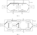
- the figures includes: Node_A, a first controller; Node_B, a second controller; Node_C, a third controller; 10, a communication network; 11, a first communication link; 12, a second communication link; 13, a third communication link; 14, a fourth communication link; Switch1, a first switch; Switch2, a second switch; Switch3, a third switch; Switch4, a fourth switch; Switch5, a fifth switch; Switch6, a sixth switch.
- FIG. 1 is a schematic diagram of an intelligent vehicle communication system according to an embodiment of the disclosure.
- the intelligent vehicle communication system includes: a first controller Node_A, a second controller Node_B, and a communication network 10.
- the communication network 10 includes: a first communication link 11 and a second communication link 12.
- the first communication link 11 connects the first controller Node_A and the second controller Node_B.
- the second communication link 12 connects the first controller Node_A and the second controller Node_B.
- the first controller Node_A and the second controller Node_B perform data transmission through the first communication link 11 and/or the second communication link 12.
- the first controller is Node_A and the second controller is Node_B.
- the first controller Node_A and the second controller Node_B include a steering wheel controller, a driving motor controller, a first steering motor controller, a second steering motor controller, a first brake actuator controller, a second brake actuator controller, a battery management unit controller, and a display controller in an intelligent vehicle. Specific types of the first controller Node_A and the second controller Node_B are not limit in the embodiments of the disclosure. If the first controller Node_A is the driving motor controller, and the second controller Node_B is the first steering motor controller, the first steering motor controller receives a source message sent by the driving motor controller.
- the first controller Node_A sends the source message to the second controller Node_B.
- the first controller Node_A is the first steering motor controller and the second controller Node_B is the driving motor controller
- the first steering motor controller receives the source message sent by the driving motor controller.
- the second controller Node_B sends the source message to the first controller Node_A.
- the first controller Node_A and the second controller Node_B provided by the embodiments of the disclosure are relative to each other.
- the first controller Node_A may act as a transmitting controller
- the second controller Node_B may act as a receiving controller.
- the first controller Node_A may act as a receiving controller
- the second controller Node_B may act as a transmitting controller.
- the communication network 10 includes the first communication link 11 and the second communication link 12.
- a first end of the first communication link 11 is communicatively connected to a first end of the first controller Node_A.
- a second end of the first communication link 11 is communicatively connected to a first end of the second controller Node_B.
- a first end of the second communication link 12 is communicatively connected to a second end of the first controller Node_B.
- a second end of the second communication link 12 is communicatively connected to a second end of the second controller Node_B.
- the first controller Node_A sends the source message to the second controller Node_B
- the first controller Node_A sends the source message to the second controller Node_B through the first communication link 11
- the first controller Node_A sends the source message to the second controller Node_B through the second communication link 12.
- the second controller Node_B receives the source message sent by the first controller Node_A through the first communication link 11, and/or the second controller Node_B receives the source message sent by the first controller Node_A through the second communication link 12.
- the first controller Node_A may send the source message to the second controller Node B through the second communication link 12.
- the first controller Node_A sends the source message to the second controller Node_B through the first communication link 11.
- the embodiments of the disclosure provide an intelligent vehicle communication system.
- the intelligent vehicle communication system includes: a first controller, a second controller, and a communication network.
- the communication network includes: a first communication link and a second communication link.
- the first controller may send the source message to the second controller through the second communication link.
- the second communication link in the communication network is failed, the first controller sends the source message to the second controller through the first communication link, to realize multi-channel data transmission between the first controller and the second controller, thereby improving the reliability of data transmission.
- FIG. 2 is a schematic diagram of an intelligent vehicle communication system according to another embodiment of the disclosure. This embodiment is based on the above embodiment provided in FIG. 1 .
- the communication network at least includes: a first switch Switch1, a second switch Switch2, a third switch Switch3, and a fourth switch Switch4.
- a first end of the first controller Node_A is communicatively connected to the first switch Switch1.
- the first switch Switch1 is communicatively connected to the second switch Switch2.
- the second switch Switch2 is communicatively connected to the fourth switch Switch4.
- the fourth switch Switch4 is communicatively connected to the third switch Switch3.
- a first end of the second controller Node_B is communicatively connected to the second switch Switch2.
- a second end of the first controller Node_A is communicatively connected to the third switch Switch3.
- the second switch Switch2 is communicatively connected to the first switch Switch1.
- the first switch Switch1 is communicatively connected to the third switch Switch3.
- the third switch Switch3 is communicatively connected to the fourth switch Switch4.
- a second end of the second controller Node_B is communicatively connected to the fourth switch Switch4.
- the first switch Switch1 is communicatively connected to the second switch Switch2, the second switch Switch2 is communicatively connected to the fourth switch Switch4, the fourth switch Switch4 is communicatively connected to the third switch Switch3.
- the second switch Switch2 is communicatively connected to the first switch Switch1
- the first switch Switch1 is communicatively connected to the third switch Switch3
- the third switch Switch3 is communicatively connected to the fourth switch Switch4.
- the switches in the first communication link 11 and the second communication link 12 are connected sequentially, so that the source message sent by a master control unit of the intelligent vehicle can reach each switch in the first communication link 11 and the second communication link 12.
- the second controller Node_B After the first communication link 11 and the second communication link 12 between the second controller Node_B and the first controller Node_A are established, when switch nodes (i.e., the first switch Switch1, the second switch Switch2, the third switch Switch3, and the fourth switch Switch4) in the first communication link 11 operate normally, and sub-links in the first communication link 11 (i.e., a connecting path of two switches that are communicatively connected, a connecting path between the first switch Switch1 and the first controller Node_A, and a connecting path between the second controller Node_B and the second switch Switch2) operate normally, the second controller Node_B receives the source message sent by the first controller Node_A through the first communication link 11.
- switch nodes i.e., the first switch Switch1, the second switch Switch2, the third switch Switch3, and the fourth switch Switch4
- sub-links in the first communication link 11 i.e., a connecting path of two switches that are communicatively connected, a connecting path between the first switch Switch1 and
- the switch nodes i.e., the first switch Switch1, the second switch Switch2, the third switch Switch3, and the fourth switch Switch4 in the second communication link 12 operate normally
- the sub-links in the second communication link 12 i.e., a connecting path of two switches that are communicatively connected, a connecting path between the third switch Switch3 and the first controller Node_A, and a connecting path between the second controller Node_B and the fourth switch Switch4 operate normally
- the second controller Node_B receives the source message sent by the first controller Node_A through the second communication link 12.
- the second controller Node_B may receive the source message sent by the first controller Node_A through the second communication link 12. If any of the switch nodes in the second communication link 12 is failed, and/or any sub-link in the second communication link 12 is failed, the second controller Node_B may receive the source message sent by the first controller Node_A through the first communication link 11, which realizes reliable data transmission between the second controller Node_B and the first controller Node_A.
- FIG. 3 is a schematic diagram of an intelligent vehicle communication system according to another embodiment of the disclosure. This embodiment is based on the embodiment provided in FIG. 2 .
- the communication network 10 further includes a fifth switch Switch5.
- the fourth switch Switch4 is communicatively connected to the third switch Switch3 through the fifth switch Switch5.
- the second switch Switch2 is communicatively connected to the first switch Switch 1 through the fifth switch Switch5.
- the communication network 10 further includes the fifth switch Switch5.
- the first end of the first controller Node_A is communicatively connected to the first switch Switch1.
- the first switch Switch1 is communicatively connected to the second switch Switch2.
- the second switch Switch2 is communicatively connected to the fourth switch Switch4.
- the fourth switch Switch4 is communicatively connected to the fifth switch Switch5.
- the fifth switch Switch5 is communicatively connected to the third switch Switch3.
- the second switch Switch2 is communicatively connected to the first end of the second controller Node_B.
- the second end of the first controller Node_A is communicatively connected to the third switch Switch3.
- the second switch Switch2 is communicatively connected to the fifth switch Switch5.
- the fifth switch Switch5 is communicatively connected to the first switch Switch1.
- the first switch Switch1 is communicatively connected to the third switch Switch3.
- the third switch Switch3 is communicatively connected to the fourth switch Switch4.
- the fourth switch Switch4 is communicatively connected to the second end of the second controller Node_B.
- FIG. 2 illustrates that the communication network 10 includes the first switch Switch 1, the second switch Switch2, the third switch Switch3, and the fourth switch Switch4.
- the communication network 10 may include the first switch Switch 1, the second switch Switch2, the third switch Switch3, the fourth switch Switch4, and the fifth switch Switch5.
- the communication network 10 is connected to the first controller Node_A and the second controller Node_B in the way shown in FIG. 3 .
- the number of switches in the communication network 10 may be other numbers, which is not specifically limited in the embodiments of the disclosure.
- reliable transmission of the source message in the communication network including 5 switches is realized by configuring the connection method of the first controller and the second controller to the first switch, the second switch, the third switch, the fourth switch, and the fifth switch in the communication network.
- FIG. 4 is a schematic diagram of an intelligent vehicle communication system according to another embodiment of the disclosure.
- the intelligent vehicle communication system further includes a third controller Node_C.
- the communication network 10 further includes a third communication link 13 and a fourth communication link 14.
- the third communication link 13 connects the second controller Node_B and the third controller Node_C
- the fourth communication link 14 connects the second controller Node_B and the third controller Node_C.
- the specific type of the third controller Node_C may be selected from a steering wheel controller, a driving motor controller, a first steering motor controller, a second steering motor controller, a first brake actuator controller, a second brake actuator controller, a battery management unit controller, and a display controller.
- the third controller Node_C may be selected in association with the first controller Node_A and the second controller Node_B, to enable information transfer between them.
- the driving motor controller sends the source message to the first steering motor controller
- the first steering motor controller after receiving the source message sent by the driving motor controller, acts according to parsed source message.
- the first steering motor controller sends the received source message sent by the driving motor controller to the display controller.
- the display controller acts according to the parsed source message.
- the first controller is the driving motor controller
- the second controller is the first steering motor controller
- the third controller is the display controller.
- the first controller is Node_A
- the second controller is Node_B
- the third controller is Node_C
- the third communication link 13 and the fourth communication link 14 are established between the second controller Node_B and the third controller as Node_C.
- the second controller Node_B serves as a connection controller between the first controller Node_A and the third controller Node_C.
- the embodiments of the disclosure provide the intelligent vehicle communication system.
- the communication system includes the first controller, the second controller and the third controller, by establishing the communication network among the first controller, the second controller and the third controller, reliable data transmission between the three controllers in the intelligent vehicle communication system is realized.
- FIG. 5 is a schematic diagram of an intelligent vehicle communication system according to another embodiment of the disclosure. This embodiment is based on the embodiment in FIG. 4 .
- the communication network at least includes the first switch Switch1, the second switch Switch2, the third switch Switch3, the fourth switch Switch4, the fifth switch Switch5, and a sixth switch Switch6.
- the first end of the first controller Node_A is communicatively connected to the first switch Switch1
- the third switch Switch3 is communicatively connected to the first switch Switch1
- the first switch Switch1 is communicatively connected to the second switch Switch2
- the second switch Switch2 is communicatively connected to the fourth switch Switch4
- the second switch Switch2 is communicatively connected to the first end of the second controller Node_B.
- the second end of the first controller Node_A is communicatively connected to the third switch Switch3
- the first switch Switch1 is communicatively connected to the third switch Switch3
- the third switch Switch3 is communicatively connected to the fourth switch Switch4
- the fourth switch Switch4 is communicatively connected to the second switch Switch2
- the fourth switch Switch4 is communicatively connected to the second end of the second controller Node_B.
- the first end of the second controller Node_B is communicatively connected to the second switch Switch2, the second switch Switch2 is communicatively connected to the fifth switch Switch5, the fifth switch Switch5 is communicatively connected to the sixth switch Switch6, and the fifth switch Switch5 is communicatively connected to a first end of the third controller Node_C.
- the second end of the second controller Node_B is communicatively connected to the fourth switch Switch4, the fourth switch Switch4 is communicatively connected to the sixth switch Switch6, the sixth switch Switch6 is communicatively connected to the fifth switch Switch5, and the sixth switch Switch6 is communicatively connected to a second end of the third controller Node_C.
- the third switch Switch3 is communicatively connected to the first switch Switch1, the first switch Switch1 is communicatively connected to the second switch Switch2, and the second switch Switch2 is communicatively connected to the fourth switch Switch4.
- the first switch Switch1 is communicatively connected to the third switch Switch3
- the third switch Switch3 is communicatively connected to the fourth switch Switch4, and the fourth switch Switch4 is communicatively connected to the second switch Switch2.
- the fourth switch Switch4 is communicatively connected to the second switch Switch2
- the second switch Switch2 is communicatively connected to the fifth switch Switch5, and the fifth switch Switch5 is communicatively connected to the sixth switch Switch6.
- the second switch Switch2 is communicatively connected to the fourth switch Switch4, the fourth switch Switch4 is communicatively connected to the sixth switch Switch6, the sixth switch Switch6 is communicatively connected to the fifth switch Switch5.
- the switches in the first communication link 11, the second communication link 12, the third communication link 13, and the fourth communication link 14 are connected sequentially, so that the source message sent by the master control unit of the intelligent vehicle can reach each of the switches in the first communication link 11, the second communication link 12, the third communication link 13 and the fourth communication link 14.
- the second controller Node_B After the first communication link 11 and the second communication link 12 between the second controller Node_B and the first controller Node_A are established, when switch nodes (i.e., the first switch Switch1, the second switch Switch2, the third switch Switch3, and the fourth switch Switch4) in the first communication link 11 operate normally, and the sub-links in the first communication link 11 (i.e., a connecting path of two switches that are communicatively connected, a connecting path between the first switch Switch1 and the first controller Node_A, and a connecting path between the second controller Node_B and the second switch Switch2) operate normally, the second controller Node_B receives the source message sent by the first controller Node_A through the first communication link 11.
- switch nodes i.e., the first switch Switch1, the second switch Switch2, the third switch Switch3, and the fourth switch Switch4
- the sub-links in the first communication link 11 i.e., a connecting path of two switches that are communicatively connected, a connecting path between the first switch Switch
- the switch nodes i.e., the first switch Switch1, the second switch Switch2, the third switch Switch3, and the fourth switch Switch4
- the sub-links in the second communication link 12 i.e., a connecting path of two switches that are communicatively connected, a connecting path between the third switch Switch3 and the first controller Node_A, and a connecting path between the second controller Node_B and the fourth switch Switch4
- the second controller Node_B receives the source message sent by the first controller Node_A through the second communication link 12.
- the third controller Node_C After the third communication link 13 and the fourth communication link 14 between the second controller Node_B and the third controller Node_C are established, when the switch nodes (i.e., the second switch Switch2, the fourth switch Switch4, the fifth switch Switch5, and the sixth switch Switch6) in the third communication link 13 operate normally, and the sub-links in the third communication link 13 (i.e., a connecting path of two switches that are communicatively connected, a connecting path between the fifth switch Switch5 and the third controller Node_C, and a connecting path between the second controller Node_B and the second switch Switch2) operate normally, the third controller Node_C receives the source message sent by the second controller Node_B through the third communication link 13.
- the switch nodes i.e., the second switch Switch2, the fourth switch Switch4, the fifth switch Switch5, and the sixth switch Switch6 in the third communication link 13
- the sub-links in the third communication link 13 i.e., a connecting path of two switches that are communicatively connected,
- the switch nodes i.e., the second switch Switch2, the fourth switch Switch4, the fifth switch Switch5, and the sixth switch Switch6 in the fourth communication link 14 operate normally
- the sub-links in the fourth communication link 14 i.e., a connecting path of two switches that are communicatively connected, a connecting path between the fourth switch Switch4 and the second controller Node_B, and a connecting path between the third controller Node_C and the sixth switch Switch6 operate normally
- the third controller Node_C receives the source message sent by the second controller Node_B through the fourth communication link 14.
- first switch Switch1, the second switch Switch2, the third switch Switch3, and the fourth switch Switch4 in the first communication link 11 and the second communication link 12 are connected in different ways. If any of the switch nodes in the first communication link 11 is failed, and/or any sub-link in the first communication link 11 is failed, the second controller Node_B may receive the source message sent by the first controller Node_A through the second communication link 12. If any of the switch nodes in the second communication link 12 is failed, and/or any sub-link in the second communication link 12 is failed, the second controller Node_B may receive the source message sent by the first controller Node_A through the first communication link 11. Therefore, reliable transmission of the source message between the second controller Node_B and the first controller Node_A is realized.
- the second switch Switch2, the fourth switch Switch4, the fifth switch Switch5 and the sixth switch Switch6 in the third communication link 13 and the fourth communication link 14 are connected in different ways. If any of the switch nodes in the third communication link 13 is failed, and/or any of the sub-links in the third communication link 13 is failed, the third controller Node_C may receive the source message sent by the second controller Node_B through the fourth communication link 14. If any of the switch nodes in the fourth communication link 14 is failed, and/or any of the sub-links in the fourth communication link 14 is failed, the third controller Node_C may receive the source message sent by the second controller Node_B through the third communication link 13. Therefore, the reliable transmission of the source message between the third controller Node_C and the second controller Node_B is realized.
- the second controller Node_B receives the source message sent by the first controller Node_A over the first communication link 11.
- the second controller Node_B receives the source message sent by the first controller Node_A over the second communication link 12.
- the third controller Node_C receives the source message sent by the second controller Node_B through the third communication link 13.
- the third controller Node_C receives the source message sent by the second controller Node_B through the fourth communication link 14.
- first switch Switch1, the second switch Switch2, the third switch Switch3, and the fourth switch Switch4 in the first communication link 11 and the second communication link 12 are connected in different ways. If any of the switch nodes in the first communication link 11 is failed, and/or any of the sub-links in the first communication link 11 is failed, the second controller Node_B may receive the source message sent by the first controller Node_A through the second communication link 12. If any of the switch nodes in the second communication link 12 is failed, and/or any of the sub-links in the second communication link 12 is failed, the second controller Node_B may receive the source message sent by the first controller Node_A through the first communication link 11.
- the second switch Switch2, the fourth switch Switch4, the fifth switch Switch5 and the sixth switch Switch6 in the third communication link 13 and the fourth communication link 14 are connected in different ways. If any of the switch nodes in the third communication link 13 is failed, and/or any of the sub-links in the third communication link 13 is failed, the third controller Node_C may receive the source message sent by the second controller Node_B through the fourth communication link 14. If any of the switch nodes in the fourth communication link 14 is failed, and/or any of the sub-links in the fourth communication link 14 is failed, the third controller Node_C may receive the source message sent by the second controller Node_B through the third communication link 13. Therefore, the reliable transmission of the source message between the third controller Node_C and the second controller Node_B is realized.
- paths for realizing the transmission of the source message between the third controller Node_C and the first controller Node_A include the first communication link 11 and the third communication link 13, the first communication link 11 and the fourth communication link 14, the second communication link 12 and the third communication link 13, and the second communication link 12 and the fourth communication link 14.
- the first controller Node_A includes at least a first Ethernet interface and a second Ethernet interface
- the second controller Node_B includes at least the first Ethernet interface and the second Ethernet interface
- the third controller Node_C includes at least the first Ethernet interface and the second Ethernet interface.
- Two ends of the first communication link 11 are electrically connected to the first Ethernet interface of the first controller Node_A and the first Ethernet interface of the second controller Node_B, respectively.
- Two ends of the second communication link 12 are electrically connected to the second Ethernet interface of the first controller Node_A and the second Ethernet interface of the second controller Node_B, respectively.
- Two ends of the third communication link 13 are electrically connected to the first Ethernet interface of the second controller Node_B and the first Ethernet interface of the third controller Node_C, respectively.
- Two ends of the fourth communication link 14 are electrically connected to the second Ethernet interface of the second controller Node_B and the second Ethernet interface of the third controller Node_C, respectively.
- the source message can be send through two communication links when the first controller Node_A, the second controller Node_B and the third controller Node_C act as transmitting controllers, and the source message may be received through two communication links when the first controller Node_A, the second controller Node_B, and the third controller Node_C act as receiving controllers.
- the communication network is isolated by a virtual local area network to form the first communication link and the second communication link.
- the communication network implements the data transmission between the first controller and the second controller based on a redundant link network adaptation protocol.
- the communication network is established between the first controller and the second controller, or the communication network is established between the first controller, the second controller and the third controller.
- Each of the first controller Node_A, the second controller Node_B, and the third controller Node_C includes a customized redundancy adaptation layer, an application layer, and a network layer.
- the customized redundancy adaptation layer provides an application programming interface (API) for the application layer, to facilitate network application development at the application layer.
- API application programming interface
- the network layer is based on a user datagram protocol (UDP), and the adaptation layer realizes reliable transmission of data to solve the problem of unreliable UDP data transmission.
- UDP user datagram protocol
Landscapes
- Engineering & Computer Science (AREA)
- Computer Networks & Wireless Communication (AREA)
- Signal Processing (AREA)
- Health & Medical Sciences (AREA)
- Computing Systems (AREA)
- General Health & Medical Sciences (AREA)
- Medical Informatics (AREA)
- Mechanical Engineering (AREA)
- Small-Scale Networks (AREA)
Abstract
Description
- This application is based on and claims priority to
Chinese patent application No. 202122251853.0, filed on September 16, 2021 - The disclosure relates to a field of automotive communication technology, in particular to an intelligent vehicle communication system.
- With the rapid development of automobile intelligence, the number of unit controllers inside the vehicle has increased dramatically, and the complexity of computing data has been further increased, which puts forward higher requirements for the communication method among the controllers of the vehicle and the topological network structure.
- The existing communication network for data transmission between the controllers in the intelligent vehicle uses a single communication link. Once the communication link is failed, end-to-end data transmission cannot be realized reliably.
- In order to solve the above technical problems or at least partially solve the above technical problems, the disclosure provides an intelligent vehicle communication system, to realize multi-channel data transmission and improves the reliability of data transmission.
- The embodiments of the disclosure provide an intelligent vehicle communication system. The system includes: a first controller, a second controller, and a communication network; in which
- the communication network includes a first communication link and a second communication link, the first communication link connects the first controller and the second controller, and the second communication link connects the first controller and the second controller; and
- the first controller and the second controller perform data transmission through the first communication link and/or the second communication link.
- Optionally, the communication network at least includes a first switch, a second switch, a third switch and a fourth switch;
- in the first communication link, a first end of the first controller is communicatively connected to the first switch, the first switch is communicatively connected to the second switch, the second switch is communicatively connected to the fourth switch, the fourth switch is communicatively connected to the third switch, and the second switch is communicatively connected to a first end of the second controller; and
- in the second communication link, a second end of the first controller is communicatively connected to the third switch, the second switch is communicatively connected to the first switch, the first switch is communicatively connected to the third switch, the third switch is communicatively connected to the fourth switch, and the fourth switch is communicatively connected to a second end of the second controller.
- Optionally, the communication network further includes a fifth switch;
- in the first communication link, the fourth switch is communicatively connected to the third switch through the fifth switch; and
- in the second communication link, the second switch is communicatively connected to the first switch through the fifth switch.
- Optionally, the system further includes a third controller; and
the communication network further includes a third communication link and a fourth communication link, the third communication link connects the second controller and the third controller, and the fourth communication link connects the second controller and the third controller. - Optionally, the communication network at least includes the first switch, the second switch, the third switch, the fourth switch, the fifth switch and a sixth switch;
- in the first communication link, a first end of the first controller is communicatively connected to the first switch, the third switch is communicatively connected to the first switch, the first switch is communicatively connected to the second switch, the second switch is communicatively connected to the fourth switch, and the second switch is communicatively connected to a first end of the second controller;
- in the second communication link, a second end of the first controller is communicatively connected to the third switch, the first switch is communicatively connected to the third switch, the third switch is communicatively connected to the fourth switch, the fourth switch is communicatively connected to the second switch, and the fourth switch is communicatively connected to a second end of the second controller;
- in the third communication link, the first end of the second controller is communicatively connected to the second switch, the second switch is communicatively connected to the fifth switch, the fifth switch is communicatively connected to the sixth switch, and the fifth switch is communicatively connected to a first end of the third controller; and
- in the fourth communication link, the second end of the second controller is communicatively connected to the fourth switch, the fourth switch is communicatively connected to the sixth switch, the sixth switch is communicatively connected to the fifth switch, and the sixth switch is communicatively connected to a second end of the third controller.
- Optionally, the first controller includes at least a first Ethernet interface and a second Ethernet interface, and the second controller includes at least a first Ethernet interface and a second Ethernet interface;
- two ends of the first communication link are electrically connected to the first Ethernet interface of the first controller and the first Ethernet interface of the second controller, respectively; and
- two ends of the second communication link are electrically connected to the second Ethernet interface of the first controller and the second Ethernet interface of the second controller, respectively.
- Optionally, the first controller includes at least a first Ethernet interface and a second Ethernet interface, the second controller includes at least a first Ethernet interface and a second Ethernet interface, and the third controller includes at least a first Ethernet interface and a second Ethernet interface;
- two ends of the first communication link are electrically connected to the first Ethernet interface of the first controller and the first Ethernet interface of the second controller, respectively;
- two ends of the second communication link are electrically connected to the second Ethernet interface of the first controller and the second Ethernet interface of the second controller, respectively;
- two ends of the third communication link are electrically connected to the first Ethernet interface of the second controller and the first Ethernet interface of the third controller, respectively; and
- two ends of the fourth communication link are electrically connected to the second Ethernet interface of the second controller and the second Ethernet interface of the third controller, respectively.
- Optionally, the communication network is isolated by a virtual local area network to form the first communication link and the second communication link.
- Optionally, the communication network implements data transmission between the first controller and the second controller based on a redundant link network adaptation protocol.
- The technical solutions provided by the embodiments of the disclosure have the following advantages over the related art.
- The embodiments of the disclosure provide an intelligent vehicle communication system. The intelligent vehicle communication system includes a first controller, a second controller, and a communication network. The communication network includes a first communication link and a second communication link. When the first communication link in the communication network is failed, the first controller may send a source message to the second controller through the second communication link. Alternatively, when the second communication link in the communication network is failed, the first controller sends the source message to the second controller through the first communication link. Therefore, multi-channel data transmission between the first controller and the second controller is realized, and the reliability of data transmission is improved.
- The accompanying drawings herein are incorporated into and constitute a part of the specification, illustrate embodiments consistent with the disclosure, and are used in combination with the specification to explain the principles of the disclosure.
- In order to more clearly illustrate the technical solutions in the embodiments or in the related art of the disclosure, the accompanying drawings to be used in the description of the embodiments or the related art will be briefly described below. Obviously, those skilled in the art can obtain other accompanying drawings from these accompanying drawings without inventive works.
-
FIG. 1 is a schematic diagram of an intelligent vehicle communication system according to an embodiment of the disclosure. -
FIG. 2 is a schematic diagram of an intelligent vehicle communication system according to another embodiment of the disclosure. -
FIG. 3 is a schematic diagram of an intelligent vehicle communication system according to another embodiment of the disclosure. -
FIG. 4 is a schematic diagram of an intelligent vehicle communication system according to another embodiment of the disclosure. -
FIG. 5 is a schematic diagram of an intelligent vehicle communication system according to another embodiment of the disclosure. - The figures includes: Node_A, a first controller; Node_B, a second controller; Node_C, a third controller; 10, a communication network; 11, a first communication link; 12, a second communication link; 13, a third communication link; 14, a fourth communication link; Switch1, a first switch; Switch2, a second switch; Switch3, a third switch; Switch4, a fourth switch; Switch5, a fifth switch; Switch6, a sixth switch.
- In order to clearly understand the above purposes, features and advantages of the disclosure, the embodiments of the disclosure will be further described below. It should be noted that the embodiments of the disclosure and features in the embodiments may be combined with each other without conflict.
- Many specific details are set forth in the following description in order to facilitate a full understanding of the disclosure, but the disclosure may also be implemented in other ways different from those described herein. Obviously, the embodiments in the disclosure are only a part of the embodiments of the disclosure and not all of them.
-
FIG. 1 is a schematic diagram of an intelligent vehicle communication system according to an embodiment of the disclosure. As illustrated inFIG. 1 , the intelligent vehicle communication system includes: a first controller Node_A, a second controller Node_B, and acommunication network 10. Thecommunication network 10 includes: afirst communication link 11 and asecond communication link 12. Thefirst communication link 11 connects the first controller Node_A and the second controller Node_B. Thesecond communication link 12 connects the first controller Node_A and the second controller Node_B. The first controller Node_A and the second controller Node_B perform data transmission through thefirst communication link 11 and/or thesecond communication link 12. - As illustrated in
FIG. 1 , the first controller is Node_A and the second controller is Node_B. The first controller Node_A and the second controller Node_B include a steering wheel controller, a driving motor controller, a first steering motor controller, a second steering motor controller, a first brake actuator controller, a second brake actuator controller, a battery management unit controller, and a display controller in an intelligent vehicle. Specific types of the first controller Node_A and the second controller Node_B are not limit in the embodiments of the disclosure. If the first controller Node_A is the driving motor controller, and the second controller Node_B is the first steering motor controller, the first steering motor controller receives a source message sent by the driving motor controller. That is, the first controller Node_A sends the source message to the second controller Node_B. If the first controller Node_A is the first steering motor controller and the second controller Node_B is the driving motor controller, the first steering motor controller receives the source message sent by the driving motor controller. That is, the second controller Node_B sends the source message to the first controller Node_A. That is, the first controller Node_A and the second controller Node_B provided by the embodiments of the disclosure are relative to each other. The first controller Node_A may act as a transmitting controller, and the second controller Node_B may act as a receiving controller. Alternatively, the first controller Node_A may act as a receiving controller and the second controller Node_B may act as a transmitting controller. - The
communication network 10 includes thefirst communication link 11 and thesecond communication link 12. A first end of thefirst communication link 11 is communicatively connected to a first end of the first controller Node_A. A second end of thefirst communication link 11 is communicatively connected to a first end of the second controller Node_B. A first end of thesecond communication link 12 is communicatively connected to a second end of the first controller Node_B. A second end of thesecond communication link 12 is communicatively connected to a second end of the second controller Node_B. When data transmission is performed between the first controller Node_A and the second controller Node_B, specifically, when the first controller Node_A sends the source message to the second controller Node_B, the first controller Node_A sends the source message to the second controller Node_B through thefirst communication link 11, and/or the first controller Node_A sends the source message to the second controller Node_B through thesecond communication link 12. The second controller Node_B receives the source message sent by the first controller Node_A through thefirst communication link 11, and/or the second controller Node_B receives the source message sent by the first controller Node_A through thesecond communication link 12. Therefore, when thefirst communication link 11 in thecommunication network 10 is failed, the first controller Node_A may send the source message to the second controller Node B through thesecond communication link 12. Alternatively, when thesecond communication link 12 in thecommunication network 10 is failed, the first controller Node_A sends the source message to the second controller Node_B through thefirst communication link 11. - The embodiments of the disclosure provide an intelligent vehicle communication system. The intelligent vehicle communication system includes: a first controller, a second controller, and a communication network. The communication network includes: a first communication link and a second communication link. When the first communication link in the communication network is failed, the first controller may send the source message to the second controller through the second communication link. Alternatively, when the second communication link in the communication network is failed, the first controller sends the source message to the second controller through the first communication link, to realize multi-channel data transmission between the first controller and the second controller, thereby improving the reliability of data transmission.
-
FIG. 2 is a schematic diagram of an intelligent vehicle communication system according to another embodiment of the disclosure. This embodiment is based on the above embodiment provided inFIG. 1 . As illustrated inFIG. 2 , the communication network at least includes: a first switch Switch1, a second switch Switch2, a third switch Switch3, and a fourth switch Switch4. In thefirst communication link 11, a first end of the first controller Node_A is communicatively connected to the first switch Switch1. The first switch Switch1 is communicatively connected to the second switch Switch2. The second switch Switch2 is communicatively connected to the fourth switch Switch4. The fourth switch Switch4 is communicatively connected to the third switch Switch3. A first end of the second controller Node_B is communicatively connected to the second switch Switch2. In thesecond communication link 12, a second end of the first controller Node_A is communicatively connected to the third switch Switch3. The second switch Switch2 is communicatively connected to the first switch Switch1. The first switch Switch1 is communicatively connected to the third switch Switch3. The third switch Switch3 is communicatively connected to the fourth switch Switch4. A second end of the second controller Node_B is communicatively connected to the fourth switch Switch4. - As illustrated in
FIG. 2 , in thefirst communication link 11, the first switch Switch1 is communicatively connected to the second switch Switch2, the second switch Switch2 is communicatively connected to the fourth switch Switch4, the fourth switch Switch4 is communicatively connected to the third switch Switch3. In thesecond communication link 12, the second switch Switch2 is communicatively connected to the first switch Switch1, the first switch Switch1 is communicatively connected to the third switch Switch3, and the third switch Switch3 is communicatively connected to the fourth switch Switch4. The switches in thefirst communication link 11 and thesecond communication link 12 are connected sequentially, so that the source message sent by a master control unit of the intelligent vehicle can reach each switch in thefirst communication link 11 and thesecond communication link 12. - After the
first communication link 11 and thesecond communication link 12 between the second controller Node_B and the first controller Node_A are established, when switch nodes (i.e., the first switch Switch1, the second switch Switch2, the third switch Switch3, and the fourth switch Switch4) in thefirst communication link 11 operate normally, and sub-links in the first communication link 11 (i.e., a connecting path of two switches that are communicatively connected, a connecting path between the first switch Switch1 and the first controller Node_A, and a connecting path between the second controller Node_B and the second switch Switch2) operate normally, the second controller Node_B receives the source message sent by the first controller Node_A through thefirst communication link 11. When the switch nodes(i.e., the first switch Switch1, the second switch Switch2, the third switch Switch3, and the fourth switch Switch4) in thesecond communication link 12 operate normally, and the sub-links in the second communication link 12 (i.e., a connecting path of two switches that are communicatively connected, a connecting path between the third switch Switch3 and the first controller Node_A, and a connecting path between the second controller Node_B and the fourth switch Switch4) operate normally, the second controller Node_B receives the source message sent by the first controller Node_A through thesecond communication link 12. In addition, since the first switch Switch1, the second switch Switch2, the third switch Switch3, and the fourth switch Switch4 in thefirst communication link 11 and thesecond communication link 12 are connected in different ways, if any of the switch nodes in thefirst communication link 11 is failed, and/or any sub-link in thefirst communication link 11 is failed, the second controller Node_B may receive the source message sent by the first controller Node_A through thesecond communication link 12. If any of the switch nodes in thesecond communication link 12 is failed, and/or any sub-link in thesecond communication link 12 is failed, the second controller Node_B may receive the source message sent by the first controller Node_A through thefirst communication link 11, which realizes reliable data transmission between the second controller Node_B and the first controller Node_A. -
FIG. 3 is a schematic diagram of an intelligent vehicle communication system according to another embodiment of the disclosure. This embodiment is based on the embodiment provided inFIG. 2 . As illustrated inFIG. 3 , thecommunication network 10 further includes a fifth switch Switch5. In thefirst communication link 11, the fourth switch Switch4 is communicatively connected to the third switch Switch3 through the fifth switch Switch5. In thesecond communication link 12, the second switch Switch2 is communicatively connected to the first switch Switch 1 through the fifth switch Switch5. - As illustrated in
FIG. 3 , thecommunication network 10 further includes the fifth switch Switch5. In thefirst communication link 11, the first end of the first controller Node_A is communicatively connected to the first switch Switch1. The first switch Switch1 is communicatively connected to the second switch Switch2. The second switch Switch2 is communicatively connected to the fourth switch Switch4. The fourth switch Switch4 is communicatively connected to the fifth switch Switch5. The fifth switch Switch5 is communicatively connected to the third switch Switch3. The second switch Switch2 is communicatively connected to the first end of the second controller Node_B. In thesecond communication link 12, the second end of the first controller Node_A is communicatively connected to the third switch Switch3. The second switch Switch2 is communicatively connected to the fifth switch Switch5. The fifth switch Switch5 is communicatively connected to the first switch Switch1. The first switch Switch1 is communicatively connected to the third switch Switch3. The third switch Switch3 is communicatively connected to the fourth switch Switch4. The fourth switch Switch4 is communicatively connected to the second end of the second controller Node_B. - It should be noted that
FIG. 2 illustrates that thecommunication network 10 includes the first switch Switch 1, the second switch Switch2, the third switch Switch3, and the fourth switch Switch4. In other possible implementations, thecommunication network 10 may include the first switch Switch 1, the second switch Switch2, the third switch Switch3, the fourth switch Switch4, and the fifth switch Switch5. When there are 5 switches in the communication network, thecommunication network 10 is connected to the first controller Node_A and the second controller Node_B in the way shown inFIG. 3 . In addition, the number of switches in thecommunication network 10 may be other numbers, which is not specifically limited in the embodiments of the disclosure. - In the intelligent vehicle communication system provided by the embodiments of the disclosure, when the communication network includes 5 switches, reliable transmission of the source message in the communication network including 5 switches is realized by configuring the connection method of the first controller and the second controller to the first switch, the second switch, the third switch, the fourth switch, and the fifth switch in the communication network.
-
FIG. 4 is a schematic diagram of an intelligent vehicle communication system according to another embodiment of the disclosure. As illustrated inFIG. 4 , the intelligent vehicle communication system further includes a third controller Node_C. Thecommunication network 10 further includes athird communication link 13 and afourth communication link 14. Thethird communication link 13 connects the second controller Node_B and the third controller Node_C, and thefourth communication link 14 connects the second controller Node_B and the third controller Node_C. - The specific type of the third controller Node_C may be selected from a steering wheel controller, a driving motor controller, a first steering motor controller, a second steering motor controller, a first brake actuator controller, a second brake actuator controller, a battery management unit controller, and a display controller. The third controller Node_C may be selected in association with the first controller Node_A and the second controller Node_B, to enable information transfer between them.
- Due to an interdependent relation among the controllers in the intelligent vehicle, for example, the driving motor controller sends the source message to the first steering motor controller, and the first steering motor controller, after receiving the source message sent by the driving motor controller, acts according to parsed source message. In addition, the first steering motor controller sends the received source message sent by the driving motor controller to the display controller. After receiving the source message sent by the first steering motor controller, the display controller acts according to the parsed source message. At this time, the first controller is the driving motor controller, the second controller is the first steering motor controller, and the third controller is the display controller. As illustrated in
FIG. 4 , the first controller is Node_A, the second controller is Node_B, and the third controller is Node_C, thethird communication link 13 and thefourth communication link 14 are established between the second controller Node_B and the third controller as Node_C. - It should be noted that in
FIG. 4 , the second controller Node_B serves as a connection controller between the first controller Node_A and the third controller Node_C. There may be an overlapped sub-link between thefirst communication link 11 and thesecond communication link 12 which are established between the second controller Node_B and the first controller Node_A and thethird communication link 13 and thefourth communication link 14 which are established between the second controller Node_B and the third controller Node_C. - The embodiments of the disclosure provide the intelligent vehicle communication system. When the communication system includes the first controller, the second controller and the third controller, by establishing the communication network among the first controller, the second controller and the third controller, reliable data transmission between the three controllers in the intelligent vehicle communication system is realized.
-
FIG. 5 is a schematic diagram of an intelligent vehicle communication system according to another embodiment of the disclosure. This embodiment is based on the embodiment inFIG. 4 . As illustrated inFIG. 5 , the communication network at least includes the first switch Switch1, the second switch Switch2, the third switch Switch3, the fourth switch Switch4, the fifth switch Switch5, and a sixth switch Switch6. - In the
first communication link 11, the first end of the first controller Node_A is communicatively connected to the first switch Switch1, the third switch Switch3 is communicatively connected to the first switch Switch1, the first switch Switch1 is communicatively connected to the second switch Switch2, the second switch Switch2 is communicatively connected to the fourth switch Switch4, and the second switch Switch2 is communicatively connected to the first end of the second controller Node_B. - In the
second communication link 12, the second end of the first controller Node_A is communicatively connected to the third switch Switch3, the first switch Switch1 is communicatively connected to the third switch Switch3, the third switch Switch3 is communicatively connected to the fourth switch Switch4, the fourth switch Switch4 is communicatively connected to the second switch Switch2, and the fourth switch Switch4 is communicatively connected to the second end of the second controller Node_B. - In the
third communication link 13, the first end of the second controller Node_B is communicatively connected to the second switch Switch2, the second switch Switch2 is communicatively connected to the fifth switch Switch5, the fifth switch Switch5 is communicatively connected to the sixth switch Switch6, and the fifth switch Switch5 is communicatively connected to a first end of the third controller Node_C. - In the
fourth communication link 14, the second end of the second controller Node_B is communicatively connected to the fourth switch Switch4, the fourth switch Switch4 is communicatively connected to the sixth switch Switch6, the sixth switch Switch6 is communicatively connected to the fifth switch Switch5, and the sixth switch Switch6 is communicatively connected to a second end of the third controller Node_C. - As illustrated in
FIG. 5 , in thefirst communication link 11, the third switch Switch3 is communicatively connected to the first switch Switch1, the first switch Switch1 is communicatively connected to the second switch Switch2, and the second switch Switch2 is communicatively connected to the fourth switch Switch4. In thesecond communication link 12, the first switch Switch1 is communicatively connected to the third switch Switch3, the third switch Switch3 is communicatively connected to the fourth switch Switch4, and the fourth switch Switch4 is communicatively connected to the second switch Switch2. In thethird communication link 13, the fourth switch Switch4 is communicatively connected to the second switch Switch2, the second switch Switch2 is communicatively connected to the fifth switch Switch5, and the fifth switch Switch5 is communicatively connected to the sixth switch Switch6. In thefourth communication link 14, the second switch Switch2 is communicatively connected to the fourth switch Switch4, the fourth switch Switch4 is communicatively connected to the sixth switch Switch6, the sixth switch Switch6 is communicatively connected to the fifth switch Switch5. The switches in thefirst communication link 11, thesecond communication link 12, thethird communication link 13, and thefourth communication link 14 are connected sequentially, so that the source message sent by the master control unit of the intelligent vehicle can reach each of the switches in thefirst communication link 11, thesecond communication link 12, thethird communication link 13 and thefourth communication link 14. - After the
first communication link 11 and thesecond communication link 12 between the second controller Node_B and the first controller Node_A are established, when switch nodes (i.e., the first switch Switch1, the second switch Switch2, the third switch Switch3, and the fourth switch Switch4) in thefirst communication link 11 operate normally, and the sub-links in the first communication link 11 (i.e., a connecting path of two switches that are communicatively connected, a connecting path between the first switch Switch1 and the first controller Node_A, and a connecting path between the second controller Node_B and the second switch Switch2) operate normally, the second controller Node_B receives the source message sent by the first controller Node_A through thefirst communication link 11. When the switch nodes (i.e., the first switch Switch1, the second switch Switch2, the third switch Switch3, and the fourth switch Switch4) in thesecond communication link 12 operate normally, and the sub-links in the second communication link 12 (i.e., a connecting path of two switches that are communicatively connected, a connecting path between the third switch Switch3 and the first controller Node_A, and a connecting path between the second controller Node_B and the fourth switch Switch4) operate normally, the second controller Node_B receives the source message sent by the first controller Node_A through thesecond communication link 12. After thethird communication link 13 and thefourth communication link 14 between the second controller Node_B and the third controller Node_C are established, when the switch nodes (i.e., the second switch Switch2, the fourth switch Switch4, the fifth switch Switch5, and the sixth switch Switch6) in thethird communication link 13 operate normally, and the sub-links in the third communication link 13 (i.e., a connecting path of two switches that are communicatively connected, a connecting path between the fifth switch Switch5 and the third controller Node_C, and a connecting path between the second controller Node_B and the second switch Switch2) operate normally, the third controller Node_C receives the source message sent by the second controller Node_B through thethird communication link 13. When the switch nodes (i.e., the second switch Switch2, the fourth switch Switch4, the fifth switch Switch5, and the sixth switch Switch6) in thefourth communication link 14 operate normally, and the sub-links in the fourth communication link 14 (i.e., a connecting path of two switches that are communicatively connected, a connecting path between the fourth switch Switch4 and the second controller Node_B, and a connecting path between the third controller Node_C and the sixth switch Switch6) operate normally, the third controller Node_C receives the source message sent by the second controller Node_B through thefourth communication link 14. - In addition, the first switch Switch1, the second switch Switch2, the third switch Switch3, and the fourth switch Switch4 in the
first communication link 11 and thesecond communication link 12 are connected in different ways. If any of the switch nodes in thefirst communication link 11 is failed, and/or any sub-link in thefirst communication link 11 is failed, the second controller Node_B may receive the source message sent by the first controller Node_A through thesecond communication link 12. If any of the switch nodes in thesecond communication link 12 is failed, and/or any sub-link in thesecond communication link 12 is failed, the second controller Node_B may receive the source message sent by the first controller Node_A through thefirst communication link 11. Therefore, reliable transmission of the source message between the second controller Node_B and the first controller Node_A is realized. - Similarly, the second switch Switch2, the fourth switch Switch4, the fifth switch Switch5 and the sixth switch Switch6 in the
third communication link 13 and thefourth communication link 14 are connected in different ways. If any of the switch nodes in thethird communication link 13 is failed, and/or any of the sub-links in thethird communication link 13 is failed, the third controller Node_C may receive the source message sent by the second controller Node_B through thefourth communication link 14. If any of the switch nodes in thefourth communication link 14 is failed, and/or any of the sub-links in thefourth communication link 14 is failed, the third controller Node_C may receive the source message sent by the second controller Node_B through thethird communication link 13. Therefore, the reliable transmission of the source message between the third controller Node_C and the second controller Node_B is realized. - After the
first communication link 11 and thesecond communication link 12 between the second controller Node_B and the first controller Node_A are established, and thethird communication link 13 and thefourth communication link 14 between the third controller Node_C and the second controller Node_B are established, when the switch nodes in thefirst communication link 11 operate normally and the sub-links in thefirst communication link 11 operate normally, the second controller Node_B receives the source message sent by the first controller Node_A over thefirst communication link 11. When the switch nodes in thesecond communication link 12 operate normally and the sub-links in thesecond communication link 12 operate normally, the second controller Node_B receives the source message sent by the first controller Node_A over thesecond communication link 12. When the switch nodes in thethird communication link 13 operate normally and the sub-links in thethird communication link 13 operate normally, the third controller Node_C receives the source message sent by the second controller Node_B through thethird communication link 13. When the switch nodes in thefourth communication link 14 operate normally and the sub-links in thefourth communication link 14 operate normally, the third controller Node_C receives the source message sent by the second controller Node_B through thefourth communication link 14. - In addition, the first switch Switch1, the second switch Switch2, the third switch Switch3, and the fourth switch Switch4 in the
first communication link 11 and thesecond communication link 12 are connected in different ways. If any of the switch nodes in thefirst communication link 11 is failed, and/or any of the sub-links in thefirst communication link 11 is failed, the second controller Node_B may receive the source message sent by the first controller Node_A through thesecond communication link 12. If any of the switch nodes in thesecond communication link 12 is failed, and/or any of the sub-links in thesecond communication link 12 is failed, the second controller Node_B may receive the source message sent by the first controller Node_A through thefirst communication link 11. Therefore, the reliable transmission of the source message between the second controller Node_B and the first controller Node_A is realized. The second switch Switch2, the fourth switch Switch4, the fifth switch Switch5 and the sixth switch Switch6 in thethird communication link 13 and thefourth communication link 14 are connected in different ways. If any of the switch nodes in thethird communication link 13 is failed, and/or any of the sub-links in thethird communication link 13 is failed, the third controller Node_C may receive the source message sent by the second controller Node_B through thefourth communication link 14. If any of the switch nodes in thefourth communication link 14 is failed, and/or any of the sub-links in thefourth communication link 14 is failed, the third controller Node_C may receive the source message sent by the second controller Node_B through thethird communication link 13. Therefore, the reliable transmission of the source message between the third controller Node_C and the second controller Node_B is realized. - Therefore, paths for realizing the transmission of the source message between the third controller Node_C and the first controller Node_A include the
first communication link 11 and thethird communication link 13, thefirst communication link 11 and thefourth communication link 14, thesecond communication link 12 and thethird communication link 13, and thesecond communication link 12 and thefourth communication link 14. - Optionally, the first controller Node_A includes at least a first Ethernet interface and a second Ethernet interface, the second controller Node_B includes at least the first Ethernet interface and the second Ethernet interface, and the third controller Node_C includes at least the first Ethernet interface and the second Ethernet interface.
- Two ends of the
first communication link 11 are electrically connected to the first Ethernet interface of the first controller Node_A and the first Ethernet interface of the second controller Node_B, respectively. - Two ends of the
second communication link 12 are electrically connected to the second Ethernet interface of the first controller Node_A and the second Ethernet interface of the second controller Node_B, respectively. - Two ends of the
third communication link 13 are electrically connected to the first Ethernet interface of the second controller Node_B and the first Ethernet interface of the third controller Node_C, respectively. - Two ends of the
fourth communication link 14 are electrically connected to the second Ethernet interface of the second controller Node_B and the second Ethernet interface of the third controller Node_C, respectively. - By setting the first controller Node_A including at least the first Ethernet interface and the second Ethernet interface, the second controller Node_B including at least the first Ethernet interface and the second Ethernet interface, and the third controller Node_C including at least the first Ethernet interface and the second Ethernet interface, the source message can be send through two communication links when the first controller Node_A, the second controller Node_B and the third controller Node_C act as transmitting controllers, and the source message may be received through two communication links when the first controller Node_A, the second controller Node_B, and the third controller Node_C act as receiving controllers.
- Optionally, the communication network is isolated by a virtual local area network to form the first communication link and the second communication link.
- Optionally, the communication network implements the data transmission between the first controller and the second controller based on a redundant link network adaptation protocol.
- In detail, the communication network is established between the first controller and the second controller, or the communication network is established between the first controller, the second controller and the third controller. Each of the first controller Node_A, the second controller Node_B, and the third controller Node_C includes a customized redundancy adaptation layer, an application layer, and a network layer. The customized redundancy adaptation layer provides an application programming interface (API) for the application layer, to facilitate network application development at the application layer. For example, to develop each functional module in the intelligent vehicle, the network layer is based on a user datagram protocol (UDP), and the adaptation layer realizes reliable transmission of data to solve the problem of unreliable UDP data transmission.
- It should be noted that the relational terms herein, such as "first" and "second", are used only for differentiating one entity or operation, from another entity or operation, which, however do not necessarily require or imply that there should be any real relationship or sequence. Moreover, the terms "comprise", "include" or any other variations thereof are meant to cover non-exclusive including, so that the process, method, article or device comprising a series of elements do not only comprise those elements, but also comprise other elements that are not explicitly listed or also comprise the inherent elements of the process, method, article or device. In the case that there are no more restrictions, an element qualified by the statement "comprises a..." does not exclude the presence of additional identical elements in the process, method, article or device that comprises the said element.
- The foregoing are only specific implementations of the disclosure to enable those skilled in the art to understand or realize the disclosure. Various modifications to these embodiments will be apparent to those skilled in the art, and the general principles defined herein may be realized in other embodiments without departing from the spirit or scope of the disclosure. Therefore, the disclosure will not be limited to these embodiments described herein, but will be subject to the broadest scope consistent with the principles and novel features disclosed herein.
Claims (9)
- An intelligent vehicle communication system, comprising: a first controller, a second controller, and a communication network; whereinthe communication network comprises a first communication link and a second communication link, the first communication link connects the first controller and the second controller, and the second communication link connects the first controller and the second controller; andthe first controller and the second controller perform data transmission through the first communication link and/or the second communication link.
- The system of claim 1, wherein the communication network at least comprises a first switch, a second switch, a third switch and a fourth switch;in the first communication link, a first end of the first controller is communicatively connected to the first switch, the first switch is communicatively connected to the second switch, the second switch is communicatively connected to the fourth switch, the fourth switch is communicatively connected to the third switch, and the second switch is communicatively connected to a first end of the second controller; andin the second communication link, a second end of the first controller is communicatively connected to the third switch, the second switch is communicatively connected to the first switch, the first switch is communicatively connected to the third switch, the third switch is communicatively connected to the fourth switch, and the fourth switch is communicatively connected to a second end of the second controller.
- The system of claim 2, wherein the communication network further comprises a fifth switch;in the first communication link, the fourth switch is communicatively connected to the third switch through the fifth switch; andin the second communication link, the second switch is communicatively connected to the first switch through the fifth switch.
- The system of any one of claims 1-3, wherein the system further comprises a third controller; and
the communication network further comprises a third communication link and a fourth communication link, the third communication link connects the second controller and the third controller, and the fourth communication link connects the second controller and the third controller. - The system of claim 4, wherein the communication network at least comprises the first switch, the second switch, the third switch, the fourth switch, the fifth switch and a sixth switch;in the first communication link, a first end of the first controller is communicatively connected to the first switch, the third switch is communicatively connected to the first switch, the first switch is communicatively connected to the second switch, the second switch is communicatively connected to the fourth switch, and the second switch is communicatively connected to a first end of the second controller;in the second communication link, a second end of the first controller is communicatively connected to the third switch, the first switch is communicatively connected to the third switch, the third switch is communicatively connected to the fourth switch, the fourth switch is communicatively connected to the second switch, and the fourth switch is communicatively connected to a second end of the second controller;in the third communication link, the first end of the second controller is communicatively connected to the second switch, the second switch is communicatively connected to the fifth switch, the fifth switch is communicatively connected to the sixth switch, and the fifth switch is communicatively connected to a first end of the third controller; andin the fourth communication link, the second end of the second controller is communicatively connected to the fourth switch, the fourth switch is communicatively connected to the sixth switch, the sixth switch is communicatively connected to the fifth switch, and the sixth switch is communicatively connected to a second end of the third controller.
- The system of any one of claims 1-5, wherein the first controller comprises at least a first Ethernet interface and a second Ethernet interface, and the second controller comprises at least a first Ethernet interface and a second Ethernet interface;two ends of the first communication link are electrically connected to the first Ethernet interface of the first controller and the first Ethernet interface of the second controller, respectively; andtwo ends of the second communication link are electrically connected to the second Ethernet interface of the first controller and the second Ethernet interface of the second controller, respectively.
- The system of any one of claims 4-6, wherein the first controller comprises at least a first Ethernet interface and a second Ethernet interface, the second controller comprises at least a first Ethernet interface and a second Ethernet interface, and the third controller comprises at least a first Ethernet interface and a second Ethernet interface;two ends of the first communication link are electrically connected to the first Ethernet interface of the first controller and the first Ethernet interface of the second controller, respectively;two ends of the second communication link are electrically connected to the second Ethernet interface of the first controller and the second Ethernet interface of the second controller, respectively;two ends of the third communication link are electrically connected to the first Ethernet interface of the second controller and the first Ethernet interface of the third controller, respectively; andtwo ends of the fourth communication link are electrically connected to the second Ethernet interface of the second controller and the second Ethernet interface of the third controller, respectively.
- The system of any one of claims 1-7, wherein the communication network is isolated by a virtual local area network to form the first communication link and the second communication link.
- The system of any one of claims 1-7, wherein the communication network implements data transmission between the first controller and the second controller based on a redundant link network adaptation protocol.
Applications Claiming Priority (2)
| Application Number | Priority Date | Filing Date | Title |
|---|---|---|---|
| CN202122251853.0U CN215682332U (en) | 2021-09-16 | 2021-09-16 | An intelligent vehicle communication system |
| PCT/CN2022/118943 WO2023040936A1 (en) | 2021-09-16 | 2022-09-15 | Intelligent vehicle communication system |
Publications (2)
| Publication Number | Publication Date |
|---|---|
| EP4404487A1 true EP4404487A1 (en) | 2024-07-24 |
| EP4404487A4 EP4404487A4 (en) | 2025-01-15 |
Family
ID=79964433
Family Applications (1)
| Application Number | Title | Priority Date | Filing Date |
|---|---|---|---|
| EP22869305.7A Withdrawn EP4404487A4 (en) | 2021-09-16 | 2022-09-15 | INTELLIGENT VEHICLE COMMUNICATION SYSTEM |
Country Status (4)
| Country | Link |
|---|---|
| US (1) | US20240383415A1 (en) |
| EP (1) | EP4404487A4 (en) |
| CN (1) | CN215682332U (en) |
| WO (1) | WO2023040936A1 (en) |
Families Citing this family (1)
| Publication number | Priority date | Publication date | Assignee | Title |
|---|---|---|---|---|
| CN215682332U (en) * | 2021-09-16 | 2022-01-28 | 北京车和家信息技术有限公司 | An intelligent vehicle communication system |
Family Cites Families (24)
| Publication number | Priority date | Publication date | Assignee | Title |
|---|---|---|---|---|
| US7020145B1 (en) * | 2001-09-24 | 2006-03-28 | Hewlett-Packard Development Company, L.P. | Network topology manager |
| CN201405922Y (en) * | 2009-03-13 | 2010-02-17 | 北京工业大学 | Steering-by-wire system for automobiles |
| DE102012000185B4 (en) * | 2012-01-09 | 2014-11-06 | Siemens Aktiengesellschaft | Method for operating a communication network and network arrangement |
| DE102012209108B4 (en) * | 2012-05-30 | 2014-05-15 | Siemens Aktiengesellschaft | Network device, network device and method for operating a network device |
| US9215168B2 (en) * | 2012-07-23 | 2015-12-15 | Broadcom Corporation | Controller area network communications using ethernet |
| US8953436B2 (en) * | 2012-09-20 | 2015-02-10 | Broadcom Corporation | Automotive neural network |
| DE102015105929A1 (en) * | 2015-04-17 | 2016-10-20 | Phoenix Contact Gmbh & Co. Kg | Automation device for redundantly controlling a bus subscriber |
| DE102015212951B4 (en) * | 2015-07-10 | 2021-10-28 | Bayerische Motoren Werke Aktiengesellschaft | Communication system for units and control units of a vehicle and vehicle comprising the communication system |
| KR102452615B1 (en) * | 2016-01-21 | 2022-10-06 | 현대자동차주식회사 | Method for transmitting data based on priority in network |
| CN105703995B (en) * | 2016-04-08 | 2019-04-16 | 同济大学 | A kind of electric intelligent automotive communication network system based on expansible loop ethernet |
| FR3053863B1 (en) * | 2016-07-11 | 2018-07-06 | Airbus Operations Sas | ONBOARD COMMUNICATION NETWORK OF A VEHICLE |
| KR102111295B1 (en) * | 2018-02-05 | 2020-05-15 | 주식회사 만도 | Apparatus and method for controlling vehicle based on redundant architecture |
| CN109116844B (en) * | 2018-08-14 | 2021-08-10 | 宁波吉利汽车研究开发有限公司 | Intelligent automobile driving system and control method |
| CN109541987B (en) * | 2018-10-17 | 2021-09-03 | 同济大学 | Plug-and-play intelligent automobile domain controller with redundancy structure and method |
| CN111071297B (en) * | 2018-10-19 | 2022-04-19 | 中车唐山机车车辆有限公司 | Train network control system and train |
| US10848331B2 (en) * | 2018-12-19 | 2020-11-24 | Nxp B.V. | Multi-node network with enhanced routing capability |
| CN109917779A (en) * | 2019-03-26 | 2019-06-21 | 中国第一汽车股份有限公司 | Redundancy control system towards L3 automatic Pilot |
| CN114726782A (en) * | 2019-05-13 | 2022-07-08 | 华为技术有限公司 | In-vehicle communication system, in-vehicle communication method and device |
| CN112242916B (en) * | 2019-07-19 | 2023-05-12 | 广州汽车集团股份有限公司 | Automobile network communication system and implementation method |
| CA3057937A1 (en) * | 2019-10-08 | 2021-04-08 | Neutron Automotive Controls Inc. | Redundant ethernet network and sensor processing system for vehicles and related methods |
| CN111845684B (en) * | 2020-07-28 | 2022-04-12 | 中国第一汽车股份有限公司 | Parking braking method, system, device, vehicle and storage medium |
| CN112572329B (en) * | 2020-12-30 | 2025-06-27 | 北京东土科技股份有限公司 | A vehicle network control system |
| CN112422700B (en) * | 2021-01-25 | 2021-05-25 | 奥特酷智能科技(南京)有限公司 | Vehicle-mounted network redundant communication method and system based on DDS (direct digital synthesizer) protocol and TSN (time delay network) technology |
| CN215682332U (en) * | 2021-09-16 | 2022-01-28 | 北京车和家信息技术有限公司 | An intelligent vehicle communication system |
-
2021
- 2021-09-16 CN CN202122251853.0U patent/CN215682332U/en active Active
-
2022
- 2022-09-15 US US18/692,417 patent/US20240383415A1/en active Pending
- 2022-09-15 WO PCT/CN2022/118943 patent/WO2023040936A1/en not_active Ceased
- 2022-09-15 EP EP22869305.7A patent/EP4404487A4/en not_active Withdrawn
Also Published As
| Publication number | Publication date |
|---|---|
| US20240383415A1 (en) | 2024-11-21 |
| EP4404487A4 (en) | 2025-01-15 |
| CN215682332U (en) | 2022-01-28 |
| WO2023040936A1 (en) | 2023-03-23 |
Similar Documents
| Publication | Publication Date | Title |
|---|---|---|
| CN101542981B (en) | Communication system with master-slave structure | |
| CN215851079U (en) | Vehicle control system and vehicle | |
| US11362859B2 (en) | In-vehicle communication device and in-vehicle system | |
| CN1550089A (en) | Vehicle active network using multiple communication paths | |
| CN105703993A (en) | Vehicle Ethernet based electric automobile distributed annular communication network architecture | |
| CN107920033B (en) | Method for operating a communication node for mirroring in a vehicle network and communication node | |
| CN207926649U (en) | Vehicle intelligent gateway and automobile | |
| CN110225071A (en) | Vehicle intelligent gateway and automobile | |
| Kraus et al. | Replacement of the Controller Area Network (CAN) protocol for future automotive bus system solutions by substitution via optical networks | |
| EP4404487A1 (en) | Intelligent vehicle communication system | |
| CN114301946B (en) | Vehicle-mounted heterogeneous network system taking TSN as backbone network and vehicle | |
| CN114338290A (en) | Vehicle-mounted Ethernet gateway system | |
| CN110203156B (en) | Distributed Wireless Body Control System | |
| CN219122584U (en) | Redundant autopilot control system and autopilot vehicle | |
| US10162777B2 (en) | Transmission unit with checking function | |
| US6609172B1 (en) | Breaking up a bus to determine the connection topology and dynamic addressing | |
| CN113169995A (en) | Method for configuring an Ethernet switch of a vehicle-mounted network of a motor vehicle | |
| US20190305983A1 (en) | Method and apparatus for configuring backup path in vehicle network | |
| CN207926623U (en) | Vehicle netbios and automobile | |
| WO2022242314A1 (en) | Can communication redundancy method and communication apparatus | |
| US8131878B2 (en) | Selective disruption of data transmission to sub-networks within a processing unit network | |
| CN110677283B (en) | Method for fast switching network dual redundancy | |
| EP1989630B1 (en) | Interface between busses of different physical layers | |
| CN116142294A (en) | Chassis domain controller, chassis system architecture and vehicle | |
| CN114338265B (en) | Program downloading system and method based on TTP/C bus |
Legal Events
| Date | Code | Title | Description |
|---|---|---|---|
| STAA | Information on the status of an ep patent application or granted ep patent |
Free format text: STATUS: THE INTERNATIONAL PUBLICATION HAS BEEN MADE |
|
| PUAI | Public reference made under article 153(3) epc to a published international application that has entered the european phase |
Free format text: ORIGINAL CODE: 0009012 |
|
| STAA | Information on the status of an ep patent application or granted ep patent |
Free format text: STATUS: REQUEST FOR EXAMINATION WAS MADE |
|
| 17P | Request for examination filed |
Effective date: 20240321 |
|
| AK | Designated contracting states |
Kind code of ref document: A1 Designated state(s): AL AT BE BG CH CY CZ DE DK EE ES FI FR GB GR HR HU IE IS IT LI LT LU LV MC MK MT NL NO PL PT RO RS SE SI SK SM TR |
|
| DAV | Request for validation of the european patent (deleted) | ||
| DAX | Request for extension of the european patent (deleted) | ||
| A4 | Supplementary search report drawn up and despatched |
Effective date: 20241218 |
|
| RIC1 | Information provided on ipc code assigned before grant |
Ipc: H04L 12/40 20060101ALI20241212BHEP Ipc: H04L 45/243 20220101ALI20241212BHEP Ipc: H04L 67/12 20220101ALI20241212BHEP Ipc: H04L 45/28 20220101ALI20241212BHEP Ipc: H04L 45/24 20220101ALI20241212BHEP Ipc: H04L 45/00 20220101ALI20241212BHEP Ipc: B60R 16/023 20060101ALI20241212BHEP Ipc: H04L 49/113 20220101ALI20241212BHEP Ipc: H04L 1/22 20060101AFI20241212BHEP |
|
| STAA | Information on the status of an ep patent application or granted ep patent |
Free format text: STATUS: THE APPLICATION HAS BEEN WITHDRAWN |
|
| 18W | Application withdrawn |
Effective date: 20250710 |