EP4404448A1 - Rotor for superconducting dynamoelectric machine - Google Patents
Rotor for superconducting dynamoelectric machine Download PDFInfo
- Publication number
- EP4404448A1 EP4404448A1 EP22869978.1A EP22869978A EP4404448A1 EP 4404448 A1 EP4404448 A1 EP 4404448A1 EP 22869978 A EP22869978 A EP 22869978A EP 4404448 A1 EP4404448 A1 EP 4404448A1
- Authority
- EP
- European Patent Office
- Prior art keywords
- rotor
- current lead
- current
- electrical machine
- rotating electrical
- Prior art date
- Legal status (The legal status is an assumption and is not a legal conclusion. Google has not performed a legal analysis and makes no representation as to the accuracy of the status listed.)
- Pending
Links
Images



Classifications
-
- H—ELECTRICITY
- H02—GENERATION; CONVERSION OR DISTRIBUTION OF ELECTRIC POWER
- H02K—DYNAMO-ELECTRIC MACHINES
- H02K55/00—Dynamo-electric machines having windings operating at cryogenic temperatures
- H02K55/02—Dynamo-electric machines having windings operating at cryogenic temperatures of the synchronous type
- H02K55/04—Dynamo-electric machines having windings operating at cryogenic temperatures of the synchronous type with rotating field windings
-
- H—ELECTRICITY
- H02—GENERATION; CONVERSION OR DISTRIBUTION OF ELECTRIC POWER
- H02K—DYNAMO-ELECTRIC MACHINES
- H02K1/00—Details of the magnetic circuit
- H02K1/02—Details of the magnetic circuit characterised by the magnetic material
-
- H—ELECTRICITY
- H02—GENERATION; CONVERSION OR DISTRIBUTION OF ELECTRIC POWER
- H02K—DYNAMO-ELECTRIC MACHINES
- H02K1/00—Details of the magnetic circuit
- H02K1/06—Details of the magnetic circuit characterised by the shape, form or construction
- H02K1/22—Rotating parts of the magnetic circuit
- H02K1/32—Rotating parts of the magnetic circuit with channels or ducts for flow of cooling medium
-
- H—ELECTRICITY
- H02—GENERATION; CONVERSION OR DISTRIBUTION OF ELECTRIC POWER
- H02K—DYNAMO-ELECTRIC MACHINES
- H02K3/00—Details of windings
- H02K3/02—Windings characterised by the conductor material
-
- H—ELECTRICITY
- H02—GENERATION; CONVERSION OR DISTRIBUTION OF ELECTRIC POWER
- H02K—DYNAMO-ELECTRIC MACHINES
- H02K9/00—Arrangements for cooling or ventilating
- H02K9/19—Arrangements for cooling or ventilating for machines with closed casing and closed-circuit cooling using a liquid cooling medium, e.g. oil
- H02K9/197—Arrangements for cooling or ventilating for machines with closed casing and closed-circuit cooling using a liquid cooling medium, e.g. oil in which the rotor or stator space is fluid-tight, e.g. to provide for different cooling media for rotor and stator
-
- H—ELECTRICITY
- H02—GENERATION; CONVERSION OR DISTRIBUTION OF ELECTRIC POWER
- H02K—DYNAMO-ELECTRIC MACHINES
- H02K9/00—Arrangements for cooling or ventilating
- H02K9/22—Arrangements for cooling or ventilating by solid heat conducting material embedded in, or arranged in contact with, the stator or rotor, e.g. heat bridges
-
- H—ELECTRICITY
- H02—GENERATION; CONVERSION OR DISTRIBUTION OF ELECTRIC POWER
- H02K—DYNAMO-ELECTRIC MACHINES
- H02K2213/00—Specific aspects, not otherwise provided for and not covered by codes H02K2201/00 - H02K2211/00
- H02K2213/03—Machines characterised by numerical values, ranges, mathematical expressions or similar information
-
- Y—GENERAL TAGGING OF NEW TECHNOLOGICAL DEVELOPMENTS; GENERAL TAGGING OF CROSS-SECTIONAL TECHNOLOGIES SPANNING OVER SEVERAL SECTIONS OF THE IPC; TECHNICAL SUBJECTS COVERED BY FORMER USPC CROSS-REFERENCE ART COLLECTIONS [XRACs] AND DIGESTS
- Y02—TECHNOLOGIES OR APPLICATIONS FOR MITIGATION OR ADAPTATION AGAINST CLIMATE CHANGE
- Y02E—REDUCTION OF GREENHOUSE GAS [GHG] EMISSIONS, RELATED TO ENERGY GENERATION, TRANSMISSION OR DISTRIBUTION
- Y02E40/00—Technologies for an efficient electrical power generation, transmission or distribution
- Y02E40/60—Superconducting electric elements or equipment; Power systems integrating superconducting elements or equipment
Definitions
- Embodiments of the present invention relate to a rotor of a superconducting rotating electrical machine.
- a rotor of a superconducting rotating electrical machine using a superconducting conductor for example, a superconducting wire such as a high temperature superconducting wire (HTS), needs to be cooled to a critical temperature or lower in order to maintain superconductivity, and needs to keep a low temperature state during operation and minimize heat entering the superconducting wire.
- HTS high temperature superconducting wire
- Intrusion heat is classified into radiant heat transfer, lean gas heat transfer, conductive heat transfer, and the like.
- a periphery of a low temperature rotor is formed as a vacuum layer having a small vacuum pressure, and a member (torque tube, current lead, or the like) that mechanically connects a low temperature portion and a normal temperature portion is cooled by a refrigerant of a gas vaporized in the low temperature rotor.
- the refrigerant vaporized in the low temperature rotor is not simply discharged and recovered, but is recovered while being effectively used as a medium for cooling these members in order to suppress heat entering the low temperature rotor due to heat conduction of a torque tube, a current lead, or the like.
- a low temperature refrigerant flows through a cooling path inside a current lead to cool the current lead.
- a configuration of the cooling path to improve heat exchange performance, increase a cooling length, and reduce a cross-sectional area of the current lead.
- the superconducting rotating electrical machine can generate a high magnetic field with a small coil, a high power density can be realized, and utilization in various fields (for example, ships, aircrafts, trains, power generation fields, industrial fields, and the like) is expected.
- a high power density is required.
- a connection portion requires a complicated structure, and a thin and long conductive pipe needs to be used, which causes an increase in an axial length of the rotor.
- rigidity against centrifugal force due to rotation is low, so that a support structure is also required.
- a structure for example, a bellows or the like having a function of alleviating thermal stress generated by thermal shrinkage at a low temperature is required.
- the direct cooling type current lead is used, the structure of the superconducting rotating electrical machine becomes complicated and the size of the superconducting rotating electrical machine becomes large.
- a rotor of a superconducting rotating electrical machine using a superconducting wire as a field winding comprises a plurality of current leads electrically connected to the field winding and spirally wound around a rotation center.
- FIG. 1 is a configuration diagram illustrating an example of a configuration of a rotor of a superconducting rotating electrical machine according to an embodiment.
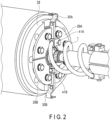
- FIG. 2 is a perspective view illustrating a structure of a part of a peripheral portion of a spiral current lead mounted on the rotor of the superconducting rotating electrical machine illustrated in FIG. 1 .
- FIG. 1 illustrates a rotor of a superconducting rotating electrical machine using, for example, a superconducting wire such as a high temperature superconducting wire (HTS) as a field winding, which configures the superconducting rotating electrical machine together with a stator (not illustrated) disposed around the rotor.
- the rotor of the superconducting rotating electrical machine includes a low temperature portion cooled to a critical temperature or lower in order to maintain superconductivity, and is configured to minimize heat entering the superconducting wire in order to maintain a low temperature state during operation.
- the rotor of the superconducting rotating electrical machine includes a current lead 1, a low temperature rotor 3, collector rings 4A and 4B, field windings (superconducting wires) 5A and 5B, a torque tube 6, a normal temperature damper 13, a vacuum insulation space 15, connection copper bands 16A and 16B, a refrigerant supply pipe 21, a refrigerant recovery pipe 22, a current lead support member 26, an indirect cooling spiral groove 27, a low temperature flange 28, flat cooling copper plates 29A and 29B, lead copper bands 30A and 30B, center hole copper bands 31A and 31B, an insulating member 34, a low temperature ring 38, current lead insertion members 41A and 41B, 42A and 42B, and the like.
- a reference sign with A is attached to an element corresponding to a positive side of a direct current
- a reference sign with B is attached to an element corresponding to a negative side of the direct current.
- the current lead 1 and the torque tube 6 that connect a low temperature portion and a normal temperature portion of the rotor in the vacuum insulation space 15 are provided between the low temperature portion and the normal temperature portion.
- the current lead 1 of the present embodiment includes a plurality of current leads wound spirally around a rotation center, and has a spiral structure, thereby making it possible to shorten an axial length of the rotor.
- the number of current leads 1 is two is exemplified, but the present invention is not limited to this example, and the number of current leads 1 may be larger than that in this example.
- the current lead 1 includes one current lead corresponding to the positive side of the direct current and one current lead corresponding to the negative side of the direct current, and both are arranged to be separated from each other by 180° in a circumferential direction of the rotor. With the arrangement shifted by 180° in this manner, it is possible to reduce weight imbalance when the rotor rotates as much as possible.
- the current lead support member 26 is a cylindrical insulating member that supports each current lead so as to cover the current lead from the periphery, and prevents the current lead from being deformed or vibrated by a centrifugal force when the rotor rotates.
- the current lead support member 26 is not necessarily required. Other members may support the individual current leads.
- each of the plurality of current leads 1 is inserted into the conductive current lead insertion member 41A or 41B, and the other end is inserted into the conductive current lead insertion member 42A or 42B.
- the current lead insertion member 41A is attached to the flat cooling copper plate 29A or formed as a part of the flat cooling copper plate 29A
- the current lead insertion member 41B is attached to the flat cooling copper plate 29B or formed as a part of the flat cooling copper plate 29B.
- One end portion of the current lead 1 corresponding to the positive side of the direct current is electrically connected to the field winding 5A through the current lead insertion member 41A, the flat cooling copper plate 29A, and the lead copper band 30A, and is thermally conductively connected to the low temperature portion including the low temperature flange 28 and the low temperature ring 38 through the current lead insertion member 41A, the flat cooling copper plate 29A, and the insulating member 34.
- the insulating member 34 (for example, aluminum nitride having high thermal conductivity) having thermal conductivity of a certain level or more is interposed between the flat cooling copper plate 29A and the low temperature flange 28, and the low temperature flange 28 can cool the flat cooling copper plate 29A while maintaining insulation between the flat cooling copper plate 29A and the low temperature flange 28.
- the other end portion of the current lead 1 corresponding to the positive side of the direct current is electrically connected to the collector ring 4A through the current lead insertion member 42A, the center hole copper band 31A, and the connection copper band 16A.
- a field current is supplied to the collector ring 4A through a brush.
- one end of the current lead 1 corresponding to the negative side of the direct current is electrically connected to the field winding 5B through the current lead insertion member 41B, the flat cooling copper plate 29B, and the lead copper band 30B, and is thermally conductively connected to the low temperature portion including the low temperature flange 28 and the low temperature ring 38 through the current lead insertion member 41B, the flat cooling copper plate 29B, and the insulating member 34.
- the insulating member 34 (for example, aluminum nitride having high thermal conductivity) having thermal conductivity of a certain level or more is interposed between flat cooling copper plate 29B and low temperature flange 28, and the low temperature flange 28 can cool the flat cooling copper plate 29B while maintaining insulation between the flat cooling copper plate 29B and the low temperature flange 28.
- the other end portion of the current lead 1 corresponding to the negative side of the direct current is electrically connected to the collector ring 4B through the current lead insertion member 42B, the center hole copper band 31B, and the connection copper band 16B.
- a field current is supplied to the collector ring 4B through a brush.
- each of the current leads 1 is wound by two turns from the current lead insertion members 41A and 41B to the current lead insertion members 42A and 42B, but the present invention is not limited to this example.
- the number of turns may be three or more.
- the number of turns may be 2.5 turns, 3.5 turns, or the like.
- an arrangement place of the members (current lead insertion member 42A, center hole copper band 31A, connection copper band 16A, collector ring 4A) corresponding to the positive side of the direct current and an arrangement place of the members (current lead insertion member 42B, center hole copper band 31B, connection copper band 16B, and collector ring 4B) corresponding to the negative side may be exchanged with each other.
- the field windings 5A and 5B which are superconducting wires, are incorporated in the low temperature rotor 3.
- the low temperature ring 38 is configured to indirectly cool the low temperature rotor 3.
- the low temperature ring 38 has a flow path through which refrigerant flows, and includes a spiral indirect cooling spiral groove 27 as a part of the flow path.
- the refrigerant is supplied to an inside of the low temperature ring 38 through the refrigerant supply pipe 21 as indicated by arrows in FIG. 1 .
- the refrigerant supplied into the low temperature ring 38 is sent to an outer diameter side of the low temperature ring 38, flows from an end of the low temperature ring 38 along the indirect cooling spiral groove 27, goes toward the cooling copper plate 29 while indirectly cooling the low temperature rotor 3, further cools the cooling copper plate 29, and then is recovered through the refrigerant recovery pipe 22.
- the current lead 1 having the spiral structure includes, for example, a copper band, and a copper band cross-sectional area and a copper band length can be determined from the following Formula (1) based on the field current, the temperature on the normal temperature portion side (high temperature end temperature), and the temperature on the low temperature portion side (low temperature end temperature) such that the amount of heat intrusion is minimized.
- L / A ⁇ / I ⁇ L o cos ⁇ 1 T L / T H where:
- the axial length of the current lead 1 itself can be freely adjusted by adjusting a spiral pitch. Furthermore, since the thermal stress relaxation of the current lead 1 due to thermal contraction at a low temperature is obtained by the spring effect of the spiral structure, a spring force can be adjusted by adjusting the cross-sectional area and the spiral length.
- the current lead 1 since the current lead 1 has a copper band having a spiral structure, a hoop resistant rigidity due to the annular structure is increased, and thus the current lead 1 can easily withstand centrifugal force, and the rigidity can be adjusted by adjusting the cross-sectional area and the spiral length.
- the current lead 1 As a material of the current lead 1, it is easy to suppress intrusion heat by using copper phosphate having a low thermal conductivity among copper bands.
- the end portion of the current lead 1 on the low temperature portion side is connected to the flat cooling copper plates 29A and 29B having a large area through the current lead insertion members 41A and 41B, and the flat cooling copper plates 29A and 29B are attached to the low temperature flange 28 through the insulating member 34 made of aluminum nitride having a high thermal conductivity by, for example, bolt fastening. Therefore, the flat cooling copper plates 29A and 29B can be more efficiently cooled by the low temperature flange 28 cooled in the low temperature portion, and the effect of suppressing the heat intrusion from the current lead 1 to the low temperature rotor 3 can be enhanced.
- the indirect cooling spiral groove 27 configuring a flow path of the refrigerant flowing inside the low temperature ring 38 has a spiral shape, the heat transfer area is large, and the low temperature rotor 3, the low temperature flange 28, and the flat cooling copper plates 29A and 29B can be more efficiently cooled.
- EBW electron beam welding
- the members are reliably connected to each other.
- a structure may be adopted in which, in each of the current lead insertion members 41A and 41B, a hole for casting solder is provided in a portion into which one end of the current lead 1 is inserted, and the solder is cast from the hole to be fixed. An example of the structure in this case is illustrated in FIGS. 3A and 3B .
- FIG. 3A is a perspective view illustrating an example of a structure in which bolts are attached to current lead insertion members 41A and 41B and holes 32 for casting solder are provided.
- FIG. 3B is a cross-sectional view illustrating an example of a cross-sectional shape of the current lead insertion member 41A illustrated in FIG. 3A as viewed in a direction of arrows A-A.
- the current lead insertion member 41A is internally provided with a stepped portion that meshes with an end of the current lead 1 to be inserted, and is provided with a bolt hole for passing the bolt 33.
- the inside of the current lead 1 is threaded to receive the insertion of the bolt 33.
- the current lead 1 has low rigidity in a direction perpendicular to the axis unique to the coil spring, so that vibration may increase.
- FIG. 4 is a perspective view illustrating an example of a structure for supporting the current lead 1.
- the current lead support members 35A and 35B illustrated in FIG. 4 are insulating members that are cylindrical in combination, and support the current lead 1 so as to cover the current lead 1 from the periphery.
- the current lead support member 35A is fixed to the flat cooling copper plate 29A side
- the current lead support member 35B is fixed to the flat cooling copper plate 29B side.
- there are a plurality of concave depressions for example, the end portion on the cooling copper plate side and the central portion for winding the tape material.
- the insulating tape material 36 is wound and tightened in the recess so that the current lead 1 is firmly supported by the cylindrical current lead support members 35A and 35B. With such a configuration, the rigidity of the spiral current lead 1 can be enhanced, and the vibration suppressing effect can be enhanced.
- the current lead 1 may be supported using a block-shaped current lead support member 37 and the tape material 36 as shown in FIG. 5 .
- the block-shaped current lead support member 37 is attached so as to be sandwiched between the current lead 1 corresponding to the positive of the direct current and the current lead 1 corresponding to the negative.
- the block-shaped current lead support member 37 and the current leads 1 on both sides are wound and tightened with the insulating tape material 36, so that the current leads 1 are firmly supported.
- the rigidity of the spiral current lead 1 can be enhanced, and the vibration suppressing effect can be enhanced.
- current lead insertion members 41C and 41D and current lead insertion members 41E and 41F are further disposed in the flat cooling copper plates 29A and 29B in addition to the above-described current lead insertion members 41A and 41B, and the current leads 1 extend spirally from each of the current lead insertion members while maintaining equal intervals in the circumferential direction of the rotor. In this case, the pitch between the adjacent current leads is 60 degrees.
- the current lead 1 extending from each of the current lead insertion members 41A, 41C, and 41E on the flat cooling copper plate 29A side forms a positive-side parallel circuit
- the current lead 1 extending from each of the current lead insertion members 41B, 41D, and 41F on the flat cooling copper plate 29B side forms a negative-side parallel circuit
- the amount of heat generated per current lead can be reduced and heat can be dispersed, so that the effect of suppressing heat entering the low temperature rotor 3 can be enhanced.
- a rotor of a superconducting rotating electrical machine capable of shortening the axial length with a simple configuration can be provided.
Landscapes
- Engineering & Computer Science (AREA)
- Power Engineering (AREA)
- Superconductive Dynamoelectric Machines (AREA)
Abstract
Description
- Embodiments of the present invention relate to a rotor of a superconducting rotating electrical machine.
- In recent years, a so-called superconducting rotating electrical machine using a superconducting conductor as a field winding has been developed. A rotor of a superconducting rotating electrical machine using a superconducting conductor, for example, a superconducting wire such as a high temperature superconducting wire (HTS), needs to be cooled to a critical temperature or lower in order to maintain superconductivity, and needs to keep a low temperature state during operation and minimize heat entering the superconducting wire.
- Intrusion heat is classified into radiant heat transfer, lean gas heat transfer, conductive heat transfer, and the like. Conventionally, in order to suppress these heat transfer, a periphery of a low temperature rotor is formed as a vacuum layer having a small vacuum pressure, and a member (torque tube, current lead, or the like) that mechanically connects a low temperature portion and a normal temperature portion is cooled by a refrigerant of a gas vaporized in the low temperature rotor. That is, the refrigerant vaporized in the low temperature rotor is not simply discharged and recovered, but is recovered while being effectively used as a medium for cooling these members in order to suppress heat entering the low temperature rotor due to heat conduction of a torque tube, a current lead, or the like.
- In the conventional technique, for example, a low temperature refrigerant flows through a cooling path inside a current lead to cool the current lead. In order to suppress heat entering the low temperature portion through the current lead, it is common to study a configuration of the cooling path to improve heat exchange performance, increase a cooling length, and reduce a cross-sectional area of the current lead.
- In recent years, a superconducting rotating electrical machine using HTS capable of obtaining superconducting characteristics at about 30 K has been developed, and not only liquid helium but also helium gas, liquid hydrogen, hydrogen gas, and the like can be used as a refrigerant.
- In addition, since the superconducting rotating electrical machine can generate a high magnetic field with a small coil, a high power density can be realized, and utilization in various fields (for example, ships, aircrafts, trains, power generation fields, industrial fields, and the like) is expected.
- In the superconducting rotating electrical machine using the superconducting wire as the field winding, a high power density is required. For example, in a current lead of a type (direct cooling type) in which cooling is performed by directly flowing a refrigerant into the current lead, sealability, thermal insulation, low heat intrusion property, and high heat exchange performance of the refrigerant are required. Therefore, a connection portion requires a complicated structure, and a thin and long conductive pipe needs to be used, which causes an increase in an axial length of the rotor. Furthermore, in a case where a thin and long copper band is used in the inside of the rotating body, rigidity against centrifugal force due to rotation is low, so that a support structure is also required. In addition, a structure (for example, a bellows or the like) having a function of alleviating thermal stress generated by thermal shrinkage at a low temperature is required. As described above, when the direct cooling type current lead is used, the structure of the superconducting rotating electrical machine becomes complicated and the size of the superconducting rotating electrical machine becomes large.
- For this reason, it is desired to present a rotor of a superconducting rotating electrical machine capable of shortening the axial length with a simple configuration.
- According to one embodiment, there is provided a rotor of a superconducting rotating electrical machine using a superconducting wire as a field winding. The rotor comprises a plurality of current leads electrically connected to the field winding and spirally wound around a rotation center.
-
-
FIG. 1 is a configuration diagram illustrating an example of a configuration of a rotor of a superconducting rotating electrical machine according to an embodiment. -
FIG. 2 is a perspective view illustrating a structure of a part of a peripheral portion of a spiral current lead mounted on the rotor of the superconducting rotating electrical machine illustrated inFIG. 1 . -
FIG. 3A is a perspective view illustrating an example of a structure in which bolts are attached to currentlead insertion members holes 32 for casting solder are provided. -
FIG. 3B is a cross-sectional view illustrating an example of a cross-sectional shape of the currentlead insertion member 41A illustrated inFIG. 3A as viewed in a direction of arrows A-A. -
FIG. 4 is a perspective view illustrating an example of a structure for supporting acurrent lead 1 using cylindrical currentlead support members tape material 36. -
FIG. 5 is a perspective view illustrating an example of a structure for supporting acurrent lead 1 using a block-shaped currentlead support member 37 and atape material 36. -
FIG. 6 is a conceptual diagram illustrating an arrangement example in a case where there are three pairs of onecurrent lead 1 corresponding to a positive side and onecurrent lead 1 corresponding to a negative side (case where the number of parallel circuits is three). - Hereinafter, embodiments will be described with reference to the drawings.
-
FIG. 1 is a configuration diagram illustrating an example of a configuration of a rotor of a superconducting rotating electrical machine according to an embodiment.FIG. 2 is a perspective view illustrating a structure of a part of a peripheral portion of a spiral current lead mounted on the rotor of the superconducting rotating electrical machine illustrated inFIG. 1 . -
FIG. 1 illustrates a rotor of a superconducting rotating electrical machine using, for example, a superconducting wire such as a high temperature superconducting wire (HTS) as a field winding, which configures the superconducting rotating electrical machine together with a stator (not illustrated) disposed around the rotor. The rotor of the superconducting rotating electrical machine includes a low temperature portion cooled to a critical temperature or lower in order to maintain superconductivity, and is configured to minimize heat entering the superconducting wire in order to maintain a low temperature state during operation. - Specifically, as illustrated in
FIG. 1 , the rotor of the superconducting rotating electrical machine includes acurrent lead 1, alow temperature rotor 3,collector rings torque tube 6, anormal temperature damper 13, avacuum insulation space 15,connection copper bands refrigerant supply pipe 21, arefrigerant recovery pipe 22, a currentlead support member 26, an indirectcooling spiral groove 27, alow temperature flange 28, flatcooling copper plates lead copper bands hole copper bands insulating member 34, alow temperature ring 38, currentlead insertion members - The
current lead 1 and thetorque tube 6 that connect a low temperature portion and a normal temperature portion of the rotor in thevacuum insulation space 15 are provided between the low temperature portion and the normal temperature portion. In particular, thecurrent lead 1 of the present embodiment includes a plurality of current leads wound spirally around a rotation center, and has a spiral structure, thereby making it possible to shorten an axial length of the rotor. Here, a case where the number ofcurrent leads 1 is two is exemplified, but the present invention is not limited to this example, and the number ofcurrent leads 1 may be larger than that in this example. - The
current lead 1 includes one current lead corresponding to the positive side of the direct current and one current lead corresponding to the negative side of the direct current, and both are arranged to be separated from each other by 180° in a circumferential direction of the rotor. With the arrangement shifted by 180° in this manner, it is possible to reduce weight imbalance when the rotor rotates as much as possible. - The current
lead support member 26 is a cylindrical insulating member that supports each current lead so as to cover the current lead from the periphery, and prevents the current lead from being deformed or vibrated by a centrifugal force when the rotor rotates. However, the currentlead support member 26 is not necessarily required. Other members may support the individual current leads. - One end of each of the plurality of
current leads 1 is inserted into the conductive currentlead insertion member lead insertion member lead insertion member 41A is attached to the flatcooling copper plate 29A or formed as a part of the flatcooling copper plate 29A, and the currentlead insertion member 41B is attached to the flatcooling copper plate 29B or formed as a part of the flatcooling copper plate 29B. - One end portion of the
current lead 1 corresponding to the positive side of the direct current is electrically connected to the field winding 5A through the currentlead insertion member 41A, the flatcooling copper plate 29A, and thelead copper band 30A, and is thermally conductively connected to the low temperature portion including thelow temperature flange 28 and thelow temperature ring 38 through the currentlead insertion member 41A, the flatcooling copper plate 29A, and theinsulating member 34. The insulating member 34 (for example, aluminum nitride having high thermal conductivity) having thermal conductivity of a certain level or more is interposed between the flatcooling copper plate 29A and thelow temperature flange 28, and thelow temperature flange 28 can cool the flatcooling copper plate 29A while maintaining insulation between the flatcooling copper plate 29A and thelow temperature flange 28. In addition, the other end portion of thecurrent lead 1 corresponding to the positive side of the direct current is electrically connected to thecollector ring 4A through the currentlead insertion member 42A, the centerhole copper band 31A, and theconnection copper band 16A. A field current is supplied to thecollector ring 4A through a brush. - Similarly, one end of the
current lead 1 corresponding to the negative side of the direct current is electrically connected to the field winding 5B through the currentlead insertion member 41B, the flatcooling copper plate 29B, and thelead copper band 30B, and is thermally conductively connected to the low temperature portion including thelow temperature flange 28 and thelow temperature ring 38 through the currentlead insertion member 41B, the flatcooling copper plate 29B, and theinsulating member 34. The insulating member 34 (for example, aluminum nitride having high thermal conductivity) having thermal conductivity of a certain level or more is interposed between flatcooling copper plate 29B andlow temperature flange 28, and thelow temperature flange 28 can cool the flatcooling copper plate 29B while maintaining insulation between the flatcooling copper plate 29B and thelow temperature flange 28. In addition, the other end portion of thecurrent lead 1 corresponding to the negative side of the direct current is electrically connected to thecollector ring 4B through the currentlead insertion member 42B, the centerhole copper band 31B, and theconnection copper band 16B. A field current is supplied to thecollector ring 4B through a brush. - In the example of
FIG. 1 , in order to form each of the current leads 1 into a spiral structure, an example is illustrated in which each of thecurrent leads 1 is wound by two turns from the currentlead insertion members lead insertion members lead insertion member 42A, centerhole copper band 31A,connection copper band 16A,collector ring 4A) corresponding to the positive side of the direct current and an arrangement place of the members (currentlead insertion member 42B, centerhole copper band 31B,connection copper band 16B, andcollector ring 4B) corresponding to the negative side may be exchanged with each other. - The
field windings low temperature rotor 3. Thelow temperature ring 38 is configured to indirectly cool thelow temperature rotor 3. For example, thelow temperature ring 38 has a flow path through which refrigerant flows, and includes a spiral indirectcooling spiral groove 27 as a part of the flow path. The refrigerant is supplied to an inside of thelow temperature ring 38 through therefrigerant supply pipe 21 as indicated by arrows inFIG. 1 . The refrigerant supplied into thelow temperature ring 38 is sent to an outer diameter side of thelow temperature ring 38, flows from an end of thelow temperature ring 38 along the indirectcooling spiral groove 27, goes toward the cooling copper plate 29 while indirectly cooling thelow temperature rotor 3, further cools the cooling copper plate 29, and then is recovered through therefrigerant recovery pipe 22. - The
current lead 1 having the spiral structure includes, for example, a copper band, and a copper band cross-sectional area and a copper band length can be determined from the following Formula (1) based on the field current, the temperature on the normal temperature portion side (high temperature end temperature), and the temperature on the low temperature portion side (low temperature end temperature) such that the amount of heat intrusion is minimized.
- L: copper band length
- A: copper band cross-sectional area
- λ: thermal conductivity
- I: field current
- Lo: the number of Lorentz
- TL: low temperature end temperature
- TH: high temperature end temperature
- In the
current lead 1, the axial length of thecurrent lead 1 itself can be freely adjusted by adjusting a spiral pitch. Furthermore, since the thermal stress relaxation of thecurrent lead 1 due to thermal contraction at a low temperature is obtained by the spring effect of the spiral structure, a spring force can be adjusted by adjusting the cross-sectional area and the spiral length. - In addition, since the
current lead 1 has a copper band having a spiral structure, a hoop resistant rigidity due to the annular structure is increased, and thus thecurrent lead 1 can easily withstand centrifugal force, and the rigidity can be adjusted by adjusting the cross-sectional area and the spiral length. - As a material of the
current lead 1, it is easy to suppress intrusion heat by using copper phosphate having a low thermal conductivity among copper bands. - The end portion of the
current lead 1 on the low temperature portion side is connected to the flatcooling copper plates lead insertion members cooling copper plates low temperature flange 28 through the insulatingmember 34 made of aluminum nitride having a high thermal conductivity by, for example, bolt fastening. Therefore, the flatcooling copper plates low temperature flange 28 cooled in the low temperature portion, and the effect of suppressing the heat intrusion from thecurrent lead 1 to thelow temperature rotor 3 can be enhanced. - In addition, since the indirect
cooling spiral groove 27 configuring a flow path of the refrigerant flowing inside thelow temperature ring 38 has a spiral shape, the heat transfer area is large, and thelow temperature rotor 3, thelow temperature flange 28, and the flatcooling copper plates - For example, bolt fastening or electron beam welding (EBW) may be applied to the electrical connection between the
current lead 1 and the flatcooling copper plates lead insertion members lead insertion members current lead 1 is inserted, and the solder is cast from the hole to be fixed. An example of the structure in this case is illustrated inFIGS. 3A and 3B . -
FIG. 3A is a perspective view illustrating an example of a structure in which bolts are attached to currentlead insertion members FIG. 3B is a cross-sectional view illustrating an example of a cross-sectional shape of the currentlead insertion member 41A illustrated inFIG. 3A as viewed in a direction of arrows A-A. - As illustrated in
FIG. 3A , bolts are attached to the currentlead insertion members - In addition, as illustrated in
FIG. 3B , the currentlead insertion member 41A is internally provided with a stepped portion that meshes with an end of thecurrent lead 1 to be inserted, and is provided with a bolt hole for passing thebolt 33. On the other hand, the inside of thecurrent lead 1 is threaded to receive the insertion of thebolt 33. - When the
bolt 33 is threaded through the bolt hole of the currentlead insertion member 41A to the inside of thecurrent lead 1 and thebolt 33 is turned, thecurrent lead 1 is pulled toward the stepped portion side of the currentlead insertion member 41A and tightened. After the bolt fastening has been performed in this manner, the solder is cast from thehole 32 for casting the solder, and the solder is spread throughout the gap. When the solder solidifies, the electrical connection between thecurrent lead 1, the currentlead insertion member 41A, and the flatcooling copper plate 29A is secured. - Depending on the spiral pitch and the number of spiral turns, the
current lead 1 has low rigidity in a direction perpendicular to the axis unique to the coil spring, so that vibration may increase. In order to prevent the vibration, it is desirable to support thecurrent lead 1 using a support member having the same shape as the currentlead support member 26 described above, another tape material, or the like. -
FIG. 4 is a perspective view illustrating an example of a structure for supporting thecurrent lead 1. - The current
lead support members FIG. 4 are insulating members that are cylindrical in combination, and support thecurrent lead 1 so as to cover thecurrent lead 1 from the periphery. For example, the currentlead support member 35A is fixed to the flatcooling copper plate 29A side, and the currentlead support member 35B is fixed to the flatcooling copper plate 29B side. In the cylindrical currentlead support members tape material 36 is wound and tightened in the recess so that thecurrent lead 1 is firmly supported by the cylindrical currentlead support members current lead 1 can be enhanced, and the vibration suppressing effect can be enhanced. - Instead of using the cylindrical current
lead support members tape material 36 as shown inFIG. 4 , thecurrent lead 1 may be supported using a block-shaped currentlead support member 37 and thetape material 36 as shown inFIG. 5 . In this case, the block-shaped currentlead support member 37 is attached so as to be sandwiched between thecurrent lead 1 corresponding to the positive of the direct current and thecurrent lead 1 corresponding to the negative. The block-shaped currentlead support member 37 and the current leads 1 on both sides are wound and tightened with the insulatingtape material 36, so that the current leads 1 are firmly supported. With such a configuration as well, the rigidity of the spiralcurrent lead 1 can be enhanced, and the vibration suppressing effect can be enhanced. - In the above description, the case where there is only one pair of one
current lead 1 corresponding to the positive side of the direct current and onecurrent lead 1 corresponding to the negative side has been exemplified. However, a plurality of pairs of onecurrent lead 1 corresponding to the positive side of the direct current and onecurrent lead 1 corresponding to the negative side may be provided. That is, a plurality ofcurrent leads 1 corresponding to the positive side may be provided to form a parallel circuit, and a plurality ofcurrent leads 1 corresponding to the negative side may be provided to form a parallel circuit. In this case, the individualcurrent leads 1 are arranged so as to form a spiral shape while maintaining equal intervals in the circumferential direction of the rotor. When the number of parallel circuits is N, a pitch between adjacent current leads is 360/N/2 (degrees). This arrangement makes it possible to balance the rotation on both the positive side and the negative side. - For example, in a case where there are three pairs of one
current lead 1 corresponding to the positive side and onecurrent lead 1 corresponding to the negative side (in a case where the number of parallel circuits is 3), as illustrated inFIG. 6 , currentlead insertion members lead insertion members cooling copper plates lead insertion members current lead 1 extending from each of the currentlead insertion members cooling copper plate 29A side forms a positive-side parallel circuit, and thecurrent lead 1 extending from each of the currentlead insertion members cooling copper plate 29B side forms a negative-side parallel circuit. - With this configuration, the amount of heat generated per current lead can be reduced and heat can be dispersed, so that the effect of suppressing heat entering the
low temperature rotor 3 can be enhanced. - As described above in detail, according to the embodiment, a rotor of a superconducting rotating electrical machine capable of shortening the axial length with a simple configuration can be provided.
- While certain embodiments have been described, these embodiments have been presented by way of example only, and are not intended to limit the scope of the inventions. Indeed, the novel embodiments described herein may be embodied in a variety of other forms; furthermore, various omissions, substitutions and changes in the form of the embodiments described herein may be made. The accompanying claims and their equivalents are intended to cover such forms or modifications as would fall within the scope of the inventions.
Claims (10)
- A rotor of a superconducting rotating electrical machine using a superconducting wire as a field winding, the rotor comprising a plurality of current leads electrically connected to the field winding and spirally wound around a rotation center.
- The rotor of a superconducting rotating electrical machine according to claim 1, wherein one end of each of the plurality of current leads is electrically connected to the field winding through a predetermined member and is thermally conductively connected to a low temperature portion in the rotor.
- The rotor of a superconducting rotating electrical machine according to claim 1, whereineach of the plurality of current leads has one end electrically connected to the field winding through a flat plate member and thermally conductively connected to a low temperature portion in the rotor, andan insulating member having thermal conductivity of a certain level or more is interposed between the flat plate member and the low temperature portion.
- The rotor of a superconducting rotating electrical machine according to any one of claims 1 to 3, whereinthe plurality of current leads include one current lead corresponding to a positive side of a direct current and one current lead corresponding to a negative side of the direct current, andthe two current leads are arranged to be shifted from each other by 180° in a circumferential direction of the rotor.
- The rotor of a superconducting rotating electrical machine according to claim 4, wherein a plurality of pairs of one current lead corresponding to the positive side and one current lead corresponding to the negative side is provided.
- The rotor of a superconducting rotating electrical machine according to claim 5, wherein the individual current leads are arranged to form a spiral shape while maintaining equal intervals in the circumferential direction of the rotor.
- The rotor of a superconducting rotating electrical machine according to any one of claims 1 to 6, further comprising a cylindrical insulating member that supports each current lead to cover the current lead from the periphery.
- The rotor of a superconducting rotating electrical machine according to any one of claims 1 to 7, wherein an insulating member is attached between the current leads.
- The rotor of a superconducting rotating electrical machine according to claim 3, further comprising a plurality of current lead insertion members attached to the flat plate member and into which one ends of the plurality of current leads are inserted, wherein each of the current lead insertion members includes a hole for casting solder in a portion into which one end of the corresponding current lead is inserted.
- The rotor of a superconducting rotating electrical machine according to claim 9, wherein bolt fastening or electron beam welding (EBW) is applied to electrical connection between each current lead and the flat plate member by the plurality of current lead insertion members.
Applications Claiming Priority (2)
| Application Number | Priority Date | Filing Date | Title |
|---|---|---|---|
| JP2021152357A JP7682745B2 (en) | 2021-09-17 | 2021-09-17 | Superconducting rotating electric motor rotor |
| PCT/JP2022/034304 WO2023042831A1 (en) | 2021-09-17 | 2022-09-14 | Rotor for superconducting dynamoelectric machine |
Publications (2)
| Publication Number | Publication Date |
|---|---|
| EP4404448A1 true EP4404448A1 (en) | 2024-07-24 |
| EP4404448A4 EP4404448A4 (en) | 2025-09-24 |
Family
ID=85602883
Family Applications (1)
| Application Number | Title | Priority Date | Filing Date |
|---|---|---|---|
| EP22869978.1A Pending EP4404448A4 (en) | 2021-09-17 | 2022-09-14 | ROTOR FOR A SUPERCONDUCTING DYNAMOELECTRIC MACHINE |
Country Status (3)
| Country | Link |
|---|---|
| EP (1) | EP4404448A4 (en) |
| JP (1) | JP7682745B2 (en) |
| WO (1) | WO2023042831A1 (en) |
Family Cites Families (5)
| Publication number | Priority date | Publication date | Assignee | Title |
|---|---|---|---|---|
| JPS5778361A (en) * | 1980-11-04 | 1982-05-17 | Hitachi Ltd | Super-conductive rotor |
| DE69528509T2 (en) * | 1994-10-27 | 2003-06-26 | General Electric Co., Schenectady | Power supply line of superconducting ceramics |
| KR100817225B1 (en) * | 2006-11-15 | 2008-03-27 | 두산중공업 주식회사 | Current lead cooling and fixing device of superconducting rotary machine |
| JP5446199B2 (en) * | 2008-10-06 | 2014-03-19 | 国立大学法人 新潟大学 | Superconducting rotating machine |
| DE102018215917A1 (en) * | 2018-08-21 | 2020-02-27 | Siemens Aktiengesellschaft | Rotor with rotor winding for operation in continuous current mode |
-
2021
- 2021-09-17 JP JP2021152357A patent/JP7682745B2/en active Active
-
2022
- 2022-09-14 EP EP22869978.1A patent/EP4404448A4/en active Pending
- 2022-09-14 WO PCT/JP2022/034304 patent/WO2023042831A1/en not_active Ceased
Also Published As
| Publication number | Publication date |
|---|---|
| WO2023042831A1 (en) | 2023-03-23 |
| JP2023044363A (en) | 2023-03-30 |
| EP4404448A4 (en) | 2025-09-24 |
| JP7682745B2 (en) | 2025-05-26 |
Similar Documents
| Publication | Publication Date | Title |
|---|---|---|
| JP6302736B2 (en) | Rotating electric machine | |
| CN107710566B (en) | Rotary motor | |
| US9915156B2 (en) | Device and method for cooling electric device having modular stators | |
| JPH04229049A (en) | Liquid cooling of rotor for electric machine | |
| US7531924B2 (en) | Cooling and supporting apparatus for current leads of superconducting rotating machine | |
| JP2004266988A (en) | Cryogenic structural enclosure for multipolar rotors with superconducting field coil windings | |
| CN101517868A (en) | Torque transmission assembly for superconducting rotating machines | |
| US20230412016A1 (en) | Displacement body for a rotor and correspondingly configured rotor | |
| US20140117793A1 (en) | Transverse flux motor | |
| US20240195253A1 (en) | Stator of an electric axial flux machine, and axial flux machine | |
| RU2563456C2 (en) | Device for support of superconducting coils in rotor of electromotive machine | |
| JP3738301B2 (en) | Electromagnetic pump | |
| JP7682745B2 (en) | Superconducting rotating electric motor rotor | |
| US20240048030A1 (en) | Electric motor with integrated cooling | |
| CA2384481C (en) | High temperature superconducting rotor power leads | |
| US3469127A (en) | Rotor cooling arrangement | |
| JP7262671B2 (en) | Chillers and semiconductor equipment | |
| US11742712B2 (en) | Rotary electric machine | |
| US11165291B2 (en) | Stator core support device and rotating electrical machine | |
| JP7437579B2 (en) | Field coil support structure and modular field coil design in superconducting machines | |
| JP7590918B2 (en) | Rotating electric machine and salient pole rotor | |
| US20200091798A1 (en) | Electric motor system | |
| JP7599626B1 (en) | Rotating electric machine and rotating electric machine system | |
| JP2007060747A (en) | Superconducting motor device and vehicle equipped with the same | |
| JP2025527766A (en) | Cooling systems for superconducting generators |
Legal Events
| Date | Code | Title | Description |
|---|---|---|---|
| STAA | Information on the status of an ep patent application or granted ep patent |
Free format text: STATUS: THE INTERNATIONAL PUBLICATION HAS BEEN MADE |
|
| PUAI | Public reference made under article 153(3) epc to a published international application that has entered the european phase |
Free format text: ORIGINAL CODE: 0009012 |
|
| STAA | Information on the status of an ep patent application or granted ep patent |
Free format text: STATUS: REQUEST FOR EXAMINATION WAS MADE |
|
| 17P | Request for examination filed |
Effective date: 20240118 |
|
| AK | Designated contracting states |
Kind code of ref document: A1 Designated state(s): AL AT BE BG CH CY CZ DE DK EE ES FI FR GB GR HR HU IE IS IT LI LT LU LV MC MK MT NL NO PL PT RO RS SE SI SK SM TR |
|
| DAV | Request for validation of the european patent (deleted) | ||
| DAX | Request for extension of the european patent (deleted) | ||
| A4 | Supplementary search report drawn up and despatched |
Effective date: 20250826 |
|
| RIC1 | Information provided on ipc code assigned before grant |
Ipc: H02K 55/04 20060101AFI20250820BHEP Ipc: H02K 1/02 20060101ALI20250820BHEP Ipc: H02K 1/32 20060101ALI20250820BHEP Ipc: H02K 3/02 20060101ALI20250820BHEP Ipc: H02K 9/197 20060101ALI20250820BHEP Ipc: H02K 9/22 20060101ALI20250820BHEP |